KR20180049022A - Heart rate monitor - Google Patents
Heart rate monitor Download PDFInfo
- Publication number
- KR20180049022A KR20180049022A KR1020187009496A KR20187009496A KR20180049022A KR 20180049022 A KR20180049022 A KR 20180049022A KR 1020187009496 A KR1020187009496 A KR 1020187009496A KR 20187009496 A KR20187009496 A KR 20187009496A KR 20180049022 A KR20180049022 A KR 20180049022A
- Authority
- KR
- South Korea
- Prior art keywords
- heart rate
- sensing unit
- user
- display
- rate monitor
- Prior art date
Links
- 230000003287 optical effect Effects 0.000 claims abstract description 13
- 210000000707 wrist Anatomy 0.000 claims description 33
- 238000000034 method Methods 0.000 claims description 7
- 238000005286 illumination Methods 0.000 claims description 6
- 239000000565 sealant Substances 0.000 claims description 5
- 239000003822 epoxy resin Substances 0.000 claims description 2
- 229920000647 polyepoxide Polymers 0.000 claims description 2
- 238000004891 communication Methods 0.000 description 26
- 238000003825 pressing Methods 0.000 description 16
- 210000003811 finger Anatomy 0.000 description 13
- 230000033001 locomotion Effects 0.000 description 9
- 230000000994 depressogenic effect Effects 0.000 description 8
- 230000006870 function Effects 0.000 description 6
- 210000000038 chest Anatomy 0.000 description 5
- 238000012546 transfer Methods 0.000 description 5
- 230000008859 change Effects 0.000 description 4
- 238000003860 storage Methods 0.000 description 4
- 230000008901 benefit Effects 0.000 description 3
- 230000000747 cardiac effect Effects 0.000 description 3
- 238000010586 diagram Methods 0.000 description 3
- 210000003414 extremity Anatomy 0.000 description 3
- 238000005259 measurement Methods 0.000 description 3
- 238000012544 monitoring process Methods 0.000 description 3
- 230000009182 swimming Effects 0.000 description 3
- 230000010267 cellular communication Effects 0.000 description 2
- 239000000356 contaminant Substances 0.000 description 2
- 239000008393 encapsulating agent Substances 0.000 description 2
- 238000005516 engineering process Methods 0.000 description 2
- 239000004973 liquid crystal related substance Substances 0.000 description 2
- 238000003032 molecular docking Methods 0.000 description 2
- 210000000115 thoracic cavity Anatomy 0.000 description 2
- 230000001133 acceleration Effects 0.000 description 1
- 230000000386 athletic effect Effects 0.000 description 1
- 230000009286 beneficial effect Effects 0.000 description 1
- 230000005540 biological transmission Effects 0.000 description 1
- 239000008280 blood Substances 0.000 description 1
- 210000004369 blood Anatomy 0.000 description 1
- 210000004204 blood vessel Anatomy 0.000 description 1
- 239000000872 buffer Substances 0.000 description 1
- 238000004364 calculation method Methods 0.000 description 1
- 239000004020 conductor Substances 0.000 description 1
- 238000007796 conventional method Methods 0.000 description 1
- 238000013500 data storage Methods 0.000 description 1
- 230000001419 dependent effect Effects 0.000 description 1
- 230000009977 dual effect Effects 0.000 description 1
- 230000000694 effects Effects 0.000 description 1
- 239000000835 fiber Substances 0.000 description 1
- 230000003760 hair shine Effects 0.000 description 1
- 238000004519 manufacturing process Methods 0.000 description 1
- 238000012986 modification Methods 0.000 description 1
- 230000004048 modification Effects 0.000 description 1
- 229920001296 polysiloxane Polymers 0.000 description 1
- 239000004814 polyurethane Substances 0.000 description 1
- 229920002635 polyurethane Polymers 0.000 description 1
- 230000008569 process Effects 0.000 description 1
- 238000012545 processing Methods 0.000 description 1
- 238000002106 pulse oximetry Methods 0.000 description 1
- 210000004243 sweat Anatomy 0.000 description 1
- 210000003813 thumb Anatomy 0.000 description 1
- 239000010981 turquoise Substances 0.000 description 1
- 238000012800 visualization Methods 0.000 description 1
- XLYOFNOQVPJJNP-UHFFFAOYSA-N water Substances O XLYOFNOQVPJJNP-UHFFFAOYSA-N 0.000 description 1
Images


Classifications
-
- A—HUMAN NECESSITIES
- A61—MEDICAL OR VETERINARY SCIENCE; HYGIENE
- A61B—DIAGNOSIS; SURGERY; IDENTIFICATION
- A61B5/00—Measuring for diagnostic purposes; Identification of persons
- A61B5/02—Detecting, measuring or recording pulse, heart rate, blood pressure or blood flow; Combined pulse/heart-rate/blood pressure determination; Evaluating a cardiovascular condition not otherwise provided for, e.g. using combinations of techniques provided for in this group with electrocardiography or electroauscultation; Heart catheters for measuring blood pressure
- A61B5/024—Detecting, measuring or recording pulse rate or heart rate
- A61B5/02438—Detecting, measuring or recording pulse rate or heart rate with portable devices, e.g. worn by the patient
-
- A—HUMAN NECESSITIES
- A61—MEDICAL OR VETERINARY SCIENCE; HYGIENE
- A61B—DIAGNOSIS; SURGERY; IDENTIFICATION
- A61B5/00—Measuring for diagnostic purposes; Identification of persons
- A61B5/0059—Measuring for diagnostic purposes; Identification of persons using light, e.g. diagnosis by transillumination, diascopy, fluorescence
-
- A—HUMAN NECESSITIES
- A61—MEDICAL OR VETERINARY SCIENCE; HYGIENE
- A61B—DIAGNOSIS; SURGERY; IDENTIFICATION
- A61B5/00—Measuring for diagnostic purposes; Identification of persons
- A61B5/02—Detecting, measuring or recording pulse, heart rate, blood pressure or blood flow; Combined pulse/heart-rate/blood pressure determination; Evaluating a cardiovascular condition not otherwise provided for, e.g. using combinations of techniques provided for in this group with electrocardiography or electroauscultation; Heart catheters for measuring blood pressure
- A61B5/024—Detecting, measuring or recording pulse rate or heart rate
- A61B5/02416—Detecting, measuring or recording pulse rate or heart rate using photoplethysmograph signals, e.g. generated by infrared radiation
- A61B5/02427—Details of sensor
-
- A—HUMAN NECESSITIES
- A61—MEDICAL OR VETERINARY SCIENCE; HYGIENE
- A61B—DIAGNOSIS; SURGERY; IDENTIFICATION
- A61B5/00—Measuring for diagnostic purposes; Identification of persons
- A61B5/68—Arrangements of detecting, measuring or recording means, e.g. sensors, in relation to patient
- A61B5/6801—Arrangements of detecting, measuring or recording means, e.g. sensors, in relation to patient specially adapted to be attached to or worn on the body surface
- A61B5/6802—Sensor mounted on worn items
- A61B5/681—Wristwatch-type devices
-
- A—HUMAN NECESSITIES
- A61—MEDICAL OR VETERINARY SCIENCE; HYGIENE
- A61B—DIAGNOSIS; SURGERY; IDENTIFICATION
- A61B5/00—Measuring for diagnostic purposes; Identification of persons
- A61B5/68—Arrangements of detecting, measuring or recording means, e.g. sensors, in relation to patient
- A61B5/6801—Arrangements of detecting, measuring or recording means, e.g. sensors, in relation to patient specially adapted to be attached to or worn on the body surface
- A61B5/6813—Specially adapted to be attached to a specific body part
- A61B5/6824—Arm or wrist
-
- A—HUMAN NECESSITIES
- A61—MEDICAL OR VETERINARY SCIENCE; HYGIENE
- A61B—DIAGNOSIS; SURGERY; IDENTIFICATION
- A61B5/00—Measuring for diagnostic purposes; Identification of persons
- A61B5/74—Details of notification to user or communication with user or patient ; user input means
- A61B5/742—Details of notification to user or communication with user or patient ; user input means using visual displays
-
- A—HUMAN NECESSITIES
- A61—MEDICAL OR VETERINARY SCIENCE; HYGIENE
- A61B—DIAGNOSIS; SURGERY; IDENTIFICATION
- A61B5/00—Measuring for diagnostic purposes; Identification of persons
- A61B5/68—Arrangements of detecting, measuring or recording means, e.g. sensors, in relation to patient
- A61B5/6801—Arrangements of detecting, measuring or recording means, e.g. sensors, in relation to patient specially adapted to be attached to or worn on the body surface
- A61B5/683—Means for maintaining contact with the body
- A61B5/6831—Straps, bands or harnesses
Landscapes
- Health & Medical Sciences (AREA)
- Life Sciences & Earth Sciences (AREA)
- Medical Informatics (AREA)
- Biophysics (AREA)
- Pathology (AREA)
- Engineering & Computer Science (AREA)
- Biomedical Technology (AREA)
- Heart & Thoracic Surgery (AREA)
- Physics & Mathematics (AREA)
- Molecular Biology (AREA)
- Surgery (AREA)
- Animal Behavior & Ethology (AREA)
- General Health & Medical Sciences (AREA)
- Public Health (AREA)
- Veterinary Medicine (AREA)
- Cardiology (AREA)
- Physiology (AREA)
- Measuring Pulse, Heart Rate, Blood Pressure Or Blood Flow (AREA)
Abstract
The heart rate monitor includes a housing 30 and an optical heart rate (OHR) sensor in the housing 30. [ The OHR sensor includes a sensing unit (not shown) including at least one optical emitter 42a, 42b arranged to illuminate light into the user's skin, and a photodetector 44 arranged to sense light reflected through the skin of the user 40). The housing (30) includes a dome portion (60). The sensing unit 40 is exposed through the surface of the dome portion 60 and protrudes above the surface of the dome portion 60.
Description
The present invention relates to a heart rate monitor, and more particularly, to a heart rate monitor including an optical heart rate (OHR) sensor. The invention also relates to a wearable heart monitor comprising an OHR sensor and the mounting of said monitor using a wrist strap. The heart rate monitor may be provided as a fitness watch, for example the heart rate monitor is removably mounted on the wrist strap. Exemplary embodiments of the present invention are directed to an apparatus for monitoring athletic activity, such as being able to be worn during exercise (running, biking, swimming, hiking, skiing, lifting gear, etc.) Display, and record a user ' s heart rate at a particular instant.
Conventional cardiac monitors typically take the form of sensors mounted on a chest strap. The capacitive sensor detects the electrical activity of the heart through the skin. This requires a thoracic strap to attach the sensor adjacent to the heart and to keep the sensor firm against the skin. The user wears a chest strap and corresponding device such as a wristwatch, and the wristwatch is wirelessly coupled to the heart rate sensor to receive and display the heart rate information. Alternatively, the sensor mounted on the chest strap may be associated with a non-worn display device such as a mobile phone or a treadmill controller.
Alternatively, some heart rate monitors may be worn on the wrist rather than using a thoracic strap. These pulse monitors require the user to touch a finger against the pad to provide a pulse rate. However, this type of monitor requires the user to stop the motion to take pulse reading and tends to be less accurate than the chest strap monitors.
More recently, strapless heart rate monitors have taken the form of wrist devices that utilize optical sensing of blood volume below the skin. International patent application WO 2013/042070 A1 discloses an optical heart monitor including a housing in the form of a clock for wearing on a user's wrist or arm. The monitor includes an LED configured to illuminate the skin of the user, which is partially absorbed by the underlying blood vessel, and the monitor further comprises a photodetector configured to sense light reflected back through the skin. The monitor processes the sensor signal and determines pulses and / or heartbeats for display.
The optical heart monitor must be mounted in stable contact with the skin during use to avoid artefacts and ensure reliable measurement. Moreover, errors in ambient light can degrade the quality of the measurement, for example when the user moves between locations of different ambient light, for example, between shade and direct sunlight. In International Application Publication WO 2013/042070 A1, an optical high-pass filter is used when a reflected light signal is detected to filter the surrounding infrared light.
It is desirable to provide an improved heart rate monitor at least in embodiments of the present invention.
The first aspect of the present invention provides a heart rate monitor comprising a housing and an optical heart rate (OHR) sensor in the housing, wherein the OHR sensor comprises a photodetector configured to sense light reflected through the skin of the user, The housing including a domed portion, the sensing unit being exposed through the surface of the dome portion, the sensing unit being exposed through the surface of the dome portion, The sensing unit protrudes above the surface of the dome portion.
According to the present invention, the housing includes a dome portion that acts to press against the user's skin when the monitor is worn during use. This helps to form an excellent contact area for the skin. Moreover, since the sensing unit protrudes above the surface of the dome portion, the sensing unit can be slightly depressed into the wearer ' s skin such that substantially ambient light can not reach the photodetector. As a result, the photodetector need not have a light emission filter for eliminating the error of light. Moreover, even when the user moves while exercising, such a structure may have a dual effect of preventing or reducing motion artefacts by helping to maintain the sensing unit in a fixed position relative to the skin It is believed. This is particularly appropriate when a strap is used to hold the monitor against the surface of a curved limb, such as an arm or leg, such as, for example, a wrist strap. Thus, the present invention overcomes the problems outlined above.
Applicants have found that the protrusions of the sensing unit have a minimum of 0.1 mm to ensure good contact with the skin of the wearer. Thus, in preferred embodiments, the sensing unit projects at least 0.1 mm above the surface of the dome portion. It is desirable that the projection of the sensing unit is limited so that it is not inconvenient for the heart rate monitor to wear. Preferably the sensing unit protrudes up to 0.8 mm above the surface of the dome portion and more preferably protrudes up to 0.5 mm.
The depth of the sensing unit can be increased to achieve its protrusion. However, this may require the manufacture of a bespoke package for the sensing unit. In a preferred set of embodiments, the sensing unit is mounted on a circuit board by a riser. By providing a riser between the circuit board and the sensing unit, a standard sensing unit package can be used.
Applicants have recognized that the potential problem that the sensing unit protrudes past the surface of the housing increases the risk of damage caused by the ingress of moisture or contaminants. This may be a problem, especially in embodiments where the heart rate monitor is provided as a fitness watch and therefore the sensing unit is likely to be damaged by sweat and / or contaminants (water, dirt, etc.) from the external environment. In a preferred set of embodiments, the heart monitor further includes a sealant around the sensing unit. In such an example, the sensing unit may be exposed through the aperture in the surface of the dome portion and the sealant may fill the aperture. Suitable encapsulants may include silicone or polyurethane. In a preferred example, the encapsulant may comprise an epoxy resin.
The OHR sensor may include any suitable sensing unit including one, two, three or more optical emitters. The light emitters may preferably comprise light emitting diodes (LEDs). In a preferred set of embodiments, the sensing unit comprises at least two, preferably three, light emitting diodes of different wavelengths. A suitable OHR sensor is, for example, Osram BioMon SFH7050. These sensors feature three LED-green (green 535 nm), red (660 nm) and IR (940 nm), and feature a large area photodiode that maximizes signal levels. The infrared LED may advantageously be used as a proximity sensor to indicate when the sensing unit is in contact with the skin. This allows the OHR sensor to automatically initiate a measurement when the monitor is attached to the skin, or to display a message that it is out of range. Although it may be sufficient to drive only one LED (e.g., green) for a heart rate monitor, red and infrared LEDs may alternatively be driven for pulse oximetry applications.
It is desirable that the OHR sensor be compact so that the heart monitor can be made thinner while enjoying the advantage of the sensing unit slightly protruding from the housing of the heart monitor. This is particularly beneficial for wrist monitors. In a preferred set of embodiments, the sensing unit is fully integrated as a package having a depth of less than 1 mm.
Some general features of a heart rate monitor that may be combined with one or more of the embodiments described above will now be described.
The housing of the heart rate monitor is preferably configured as a single integral casing, which is preferably sealed to be watertight, so that the monitor can be used for outdoor exercise and swimming in humid weather.
The OHR sensor may include a processor and a battery. The processor may be configured to analyze the received optical signal, for example in a photodetector, for display and / or transmission purposes. The OHR sensor may include a memory coupled to the processor. This means that HR data can be stored by the device and subsequently downloaded. The OHR sensor may include an input / output (I / O) device to transfer data to and from the device and to provide power to recharge the battery. In some instances, the OHR sensor can simply act as a sensor hub, collecting and / or transmitting heartbeat data for display by other devices. This allows the size of the heart rate monitor to be minimized.
In a preferred set of embodiments, the heart rate monitor includes a display for displaying heart rate information to a user. The display may comprise, for example, a liquid crystal display (LCD). More preferably, the heart rate monitor includes an OHR sensor and / or an input device for controlling the display. Such an input device allows the user to change the relevant function, for example, to change the applicable HR area. In various embodiments, the input device is spaced from the display. In embodiments in which the monitor is mounted on a wrist strap, the input device is preferably spaced from the display in the lengthwise direction of the strap. The display can be configured to display alphanumeric characters or icons such that the upper portions of the character or icon are oriented toward the first side of the housing and the lower portions of the character or icon are positioned toward the opposite second side of the housing do. The input device is preferably spaced from the display in the direction from the first side to the second side. This configuration is useful when the user wears the display on the back of the wrist, allowing the user to easily view the display while controlling the device through an input device spaced from the display. Less preferably, the input device may be spaced from the display in a direction from the second side of the housing to the first side. This arrangement may be useful, for example, when the monitor is secured to the strap by a strap on a handle bar sonor of a bicycle or to a strap by another device, which allows the user to easily access the input device from above, Because it can point to the user.
The input device is preferably configured to control the display and associated electrical components in use. For example, the input device may be configured for navigation through a menu displayed on the display. For example, the input device can control the function of the OHR sensor. The input device is thus electrically connected to electronic components in the housing. For example, a ribbon lead may extend between the housing and the input device.
The input device preferably has a substantially planar surface, which is arranged substantially parallel to the upper surface of the module and above the upper surface. The input device is preferably configured to detect movement of the user's finger across a substantially planar surface to provide an input for controlling the monitor, for example, configured to navigate a menu displayed on the display.
Thus, the input device may include a touchpad (or trackpad), which may include capacitive sensing versus conductance to convert the motion of the user's finger into an input that controls the OHR sensor, Use conductance sensing. The touchpad may include a one-dimensional touch pad, which may sense movement along a single axis, e.g., left-right or up-down. In other more preferred embodiments, the touchpad may include a two-dimensional touch pad, which moves on at least a left-right and up-down, or any direction, on a plane defined by a substantially planar surface of the input device Can be detected. In another, in a less preferred embodiment, the input device may include a pointing stick (or trackpad), which may be connected to the user's finger by, for example, using a pair of resistive strain gauges Detects the applied force, and changes it to input for monitor control.
Alternatively, the input device may include two actuators and a two way button with a continuous pressing surface, such that when the first portion of the pressing surface is depressed, the first one of the actuators engages the module And the second actuator of the actuators is actuated to provide a second input for controlling the monitor when the second portion of the pressing surface is depressed.
Alternatively, the input device may include a four-way button, which has a continuous pressing surface and four actuators, such that when the first portion of the pressing surface is depressed, the first of the actuators An actuator is activated to provide a first input for controlling the monitor and a second one of the actuators when the second portion of the pressing surface is depressed is operated to provide a second input for controlling the monitor, A third one of the actuators is actuated to provide a third input for controlling the monitor, and when a fourth portion of the pressing surface is depressed, a fourth one of the actuators is actuated by the monitor The button is configured to be operated to provide a fourth input to control. The pressure surface described herein is preferably a substantially planar surface on and parallel to a portion of the lower surface that, in use, contacts the user ' s limb. The input device may also include any one or more mechanically actuated buttons or mechanically disabled buttons, for example a virtual button on a touch-sensitive user interface, as desired.
The input device is preferably configured, in addition or as an alternative, to operate by being pushed in a direction from the top surface toward the bottom surface in a direction substantially perpendicular to the substantially planar surface. This allows the user to use a single finger to operate the input device. The user does not need to use the second finger of the same hand to balance the pressing of the input device because the input device is arranged to be pressed against the wrist of the wearer of the monitor.
To detect movement of the user's finger across a substantially flat surface and to be depressed against the user's limbs, such as when the input device comprises a touchpad that can be depressed, In embodiments, the detected movement of the user's finger is used to navigate a menu to identify the function to be selected, and the pressing of the input device is used to select the identified function.
Additionally or alternatively, the display is preferably substantially planar and disposed in a first plane, the input device having a substantially planar pressing surface disposed in a second plane, the first plane and the second plane having angular And the angle between the first plane and the second plane is less than 90 degrees, alternatively between 20 and 70 degrees. That is, the planes are imaginary intersecting planes and the sides of the planes facing the user's arm or wrist in use form an angle therebetween at the intersection, which preferably is greater than 90 degrees and 180 degrees Lt; / RTI > By providing a surface at an angle to each other, the user can have a good viewing angle of the display while using the input device, when the monitor is attached to the user's wrist in use. The input device is spaced from the display housing and thus is spaced from the back of the user's wrist and from the side of the wrist during use so that the user is pressed against the user's wrist when the input device is pressed, The angle may direct the input device to provide the necessary opposing force to match. Thus, the input device can be operated with a single finger and can be operated without the need for the second finger of the same hand to balance the biasing force, as in conventional clocks with buttons around the periphery of the display .
Additionally or alternatively, the display preferably has a casing physically connected to the input device by a connecting portion, wherein the connecting portion is curved or angled along the direction from the display to the input device. When the display is in use at the top of the user's wrist, the connecting portion may be curved or otherwise extended around the wrist so that the connecting portion may be curved or angled so that the input device is positioned on the side of the user's wrist. have. The monitor is preferably configured such that the input device is located on the medial side of the user's wrist when the display is positioned on the back of the wrist, the medial side being the side facing the user's body when the back of the hand is vertically upwardly directed . In other less preferred embodiments, the wrist strap may form the connecting portion connecting the display casing and the input device. The strap may be formed from one or more pivotable sections or may be flexible to pivot or bend to form a curved or angled connection portion.
The heart rate monitor preferably includes a processor configured to control the OHR sensor and display. The display can visually display heart rate (HR) information, e.g., current HR (bpm), mean HR (bpm), maximum HR, minimum HR; Current HR area; Graphical representation of HR change over time); And a graphical representation of the percentage of time spent in each of the plurality of HR regions over time. Additionally or alternatively, the heart rate monitor may include an audible output, such as, for example, a beeper, and / or a tactile output, e.g., a vibrator, to alert the user of a change in HR data.
The present invention also provides a fitness watch that includes the heart rate monitor described above. That is, the heart rate monitor may take the form of a fitness watch, and all references to the heart rate monitor here may alternatively be taken as a reference to a fitness watch. Such a fitness watch preferably includes a processor for controlling the heart rate monitor and any other components of the watch. The processor may be coupled to a means for tracking the location of the user as the user moves from one location to another, such as by utilizing information received from a global navigation satellite signal, or by using a WiFi access point or cellular communication network and accesses and receives information from cellular communication networks. In preferred embodiments, the watch is a global navigation satellite system, such as a GPS and / or GLONASS receiver, for receiving a satellite signal indicative of the position and optionally the speed of the receiver (and hence the user) (GNSS) receiver, which receives updated information at regular intervals. As it should be understood, this adds the ability to track the user's location when the user moves from one location to another. The GNSS receiver may include, for example, an antenna in the form of a patch antenna used to determine the position and movement of the user.
Alternatively, or additionally, the fitness watch may include: a GPS receiver, a speed sensor, a cadence sensor, an accelerometer, a gyroscope, an altimeter, a pressure sensor (e.g., a dive depth gauge), an electronic compass, (E.g., capable of transmitting signals from one or more body-worn sensors), such as a Bluetooth module (e.g., a Bluetooth low energy (BLE) In embodiments where the clock includes a wireless communication device, it may be configured to receive data from other sensors, such as a foot pod sensor or a speed / beat sensor, The wireless communication device may be configured to communicate with an external heart monitor, for example, a user wearing a wearable chest strap, The emitter and communication. As Additionally or alternatively, the wireless communications device may be configured to transmit data to at least one external device (e.g., a mobile telephone device).
The watch may include one or more electrical connectors for electrically connecting the dock or cable to charge the battery and / or transfer data to or from the processor. It is contemplated that any known electrical connector may be employed. However, in preferred embodiments, the one or more electrical connectors include electrical contacts, which may be flat and may be disposed to substantially coincide with the bottom surface of the housing, or may be recessed at the bottom surface For example, to contact a corresponding pogo pin in a singing system). Although in the preferred embodiments the electrical contacts are located at the lower surface beneath the input device, for example, even at the end from the display, the electrical contacts can be positioned at any part of the lower surface of the housing as desired. This allows the user to see the display when the clock is located in the docking system.
In at least some embodiments, the heart rate monitor may be permanently attached to the strap to form a fitness watch. For example, a heart rate monitor can be integrated with a strap. However, in various embodiments of the present invention, the heart rate monitor may be removably mounted to the wrist strap. For example, the strap may include a center mount, and a heart monitor is removably connected to the center mount. This may be accomplished, for example, by using a docking station connected to a computer to allow the user to repeatedly engage the strap so that the user can dock the heart rate monitor to allow transfer of power and / To be disengaged. Additionally or alternatively, the same strap may be used interchangeably to accommodate different heart rate monitors or other units, and may be used for position determination, such as, for example, a Global Navigation Satellite System (GNSS) receiver, such as GPS and / or GLONASS May be used to mount such a watch module, including means.
The center mount provided by the strap may include a physical connector for a heart rate monitor and may include, for example, a mechanical and / or magnetic connection system. In a preferred set of embodiments, the center mount may include a through hole in the strap, for example, and a heart rate monitor may be inserted therein. The heart rate monitor may include one or more protrusions and / or recesses for releasably associating with a corresponding feature of the aperture. Preferably, the strap includes at least two apertures, and in embodiments in which the heart rate monitor includes a display and an input device, each of the display and the input device projects through individual apertures in the strap.
The invention, which may be embodied in any of its embodiments or other aspects, may encompass any of the features described in connection with other aspects or embodiments of the present invention to the contrary.
Advantages of these embodiments will be described hereinafter, and other details and features of each of these embodiments are defined in the appended dependent claims and elsewhere in the following detailed description.
Various aspects of the principles of the present invention and configurations for embodying these principles will now be described by way of example with reference to the accompanying drawings.
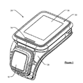
1 shows a perspective view of a heart monitor module.
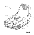
Figure 2 shows the module of Figure 1 shown from below.
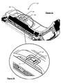
Figures 3a and 3b show a side view and an enlarged view, respectively, of the module.
Figures 4A and 4B show a side view and an enlarged view, respectively, of the module.
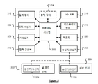
Figure 5 schematically illustrates electronic components of a fitness watch according to a preferred embodiment.
6 is a schematic diagram of a manner in which a fitness clock can receive information over a wireless communication channel.
Preferred embodiments of the present invention will now be described with particular reference to a fitness watch or a sports watch where access to GPS positioning data is made. A fitness watch or a sports watch of the type described is often assisted by an athlete during their running or practice, for example, monitoring the speed and distance of the user and providing such information to the user. However, it will be appreciated that such devices may be configured to be carried by a user or connected to or "docked" in a known manner to a vehicle such as a bicycle, kayak, or the like.
Generally, GPS is a satellite-radio board navigation system that allows to determine continuous position, velocity, time and, in some cases, direction information for an unlimited number of users. As previously known as NAVSTAR, the GPS includes a plurality of satellites orbiting the earth in an extremely precise orbit. Based on this precise trajectory, the GPS satellites can relay their position to any number of receiving units.
The GPS system is particularly performed when a device installed to receive GPS data begins to scan the radio frequency of the GPS received signals. Upon receiving a radio signal from a GPS satellite, the device determines the exact location of the satellite via one of a plurality of different conventional methods. It should be noted that the device will continue to scan the signal until it has acquired at least three different satellite signals in most cases (the location can be determined with only two signals, but not normally, using other triangulation techniques do). By performing a geometric triangulation, the receiver uses three known positions to determine its own two-dimensional position with respect to the satellite. This can be done in a known manner. Moreover, by acquiring the third satellite signal, the receiving device can calculate the three-dimensional position in a manner known by the same geometric calculation. The position data and velocity data may be updated on a continuous basis in real time by an unlimited number of users.
Figure 5 illustrates, in block component format, the electronic components of a
The
5 further illustrates an operational connection between the
The
The device may receive data from other sensors and may receive data from, for example, a
The
It will also be appreciated by those skilled in the art that the electronic components shown in FIG. 5 are powered by the
The
As those skilled in the art will appreciate, different configurations of the components shown in FIG. 5 may be considered within the scope of the invention. For example, the components shown in FIG. 5 may be communicated with each other through a wired and / or wireless connection, or the like.
In FIG. 6,
The
The
In one exemplary configuration, the
The
The
The
As will be appreciated, the
Figures 1 to 4 provide an example of a fitness monitoring module that can be removably connected to a wrist strap (not shown), as described above. In some embodiments, the
Figure 1 shows a perspective view of a
The
The
The positioning of the
Fig. 2 shows a perspective view from below of the
Figures 3a and 3b show in detail how the
The
The user interface of the module includes an
Although various aspects and embodiments of the present invention have been described, it will be understood that the scope of the present invention is not limited to the specific configurations described herein but extends to cover all configurations, modifications and variations that fall within the scope of the appended claims. Will be.
For example, it will be appreciated that while the preferred embodiment described in the above described description relates to a heart rate monitor module not associated with a strap, the module may be permanently or removably mounted to a wrist strap. Moreover, although modules are described as having a display and / or input device, they are optional components. Suitable modules include a battery and a processor, which are coupled to one or more of an optional display, an optional input device, a memory, a wireless transceiver, and input / output devices such as electrical contacts.
Finally, it should be noted that while the appended claims describe specific combinations of features described herein, it is to be understood that the invention is not to be limited to the specific combinations claimed hereinafter, And extends to encompass any combination of embodiments or features disclosed herein whether or not specifically enumerated herein.
200.
206.
220.
Claims (12)
Wherein the sensing unit protrudes at least 0.1 mm above the surface of the dome portion.
Wherein the sensing unit protrudes up to 0.8 mm above the surface of the dome portion and preferably protrudes up to 0.5 mm.
Wherein the sensing unit is mounted on the circuit board by a riser.
A heart rate monitor, further comprising a sealant around the sensing unit.
The sensing unit is exposed through the aperture in the surface of the dome portion, and the sealant fills the aperture.
Wherein the sealant comprises an epoxy resin.
Wherein the sensing unit comprises three light emitting diodes of different wavelengths.
Wherein the sensing unit is fully integrated as a package having a depth less than 1 mm.
A heart rate monitor, further comprising a display for displaying heart rate information to a user.
Further comprising one or more illumination devices in addition to the display, wherein the one or more illumination devices are configured to: (i) flash with a frequency according to the heartbeat information; And / or (ii) the color of the illuminated light corresponds to a predetermined heart rate region; Controlled, heart rate monitor.
Applications Claiming Priority (3)
| Application Number | Priority Date | Filing Date | Title |
|---|---|---|---|
| GB1515657.3 | 2015-09-03 | ||
| GBGB1515657.3A GB201515657D0 (en) | 2015-09-03 | 2015-09-03 | Heart rate monitor |
| PCT/EP2016/070734 WO2017037242A1 (en) | 2015-09-03 | 2016-09-02 | Heart rate monitor |
Publications (1)
| Publication Number | Publication Date |
|---|---|
| KR20180049022A true KR20180049022A (en) | 2018-05-10 |
Family
ID=54345745
Family Applications (1)
| Application Number | Title | Priority Date | Filing Date |
|---|---|---|---|
| KR1020187009496A KR20180049022A (en) | 2015-09-03 | 2016-09-02 | Heart rate monitor |
Country Status (7)
| Country | Link |
|---|---|
| US (1) | US20180256049A1 (en) |
| EP (1) | EP3344131A1 (en) |
| JP (1) | JP2018529416A (en) |
| KR (1) | KR20180049022A (en) |
| CN (1) | CN108024744A (en) |
| GB (1) | GB201515657D0 (en) |
| WO (1) | WO2017037242A1 (en) |
Families Citing this family (26)
| Publication number | Priority date | Publication date | Assignee | Title |
|---|---|---|---|---|
| KR101776098B1 (en) | 2014-09-02 | 2017-09-07 | 애플 인크. | Physical activity and workout monitor |
| CN107921317B (en) | 2015-08-20 | 2021-07-06 | 苹果公司 | Motion-based dial and complex function block |
| DK201770423A1 (en) | 2016-06-11 | 2018-01-15 | Apple Inc | Activity and workout updates |
| US11216119B2 (en) | 2016-06-12 | 2022-01-04 | Apple Inc. | Displaying a predetermined view of an application |
| US10736543B2 (en) | 2016-09-22 | 2020-08-11 | Apple Inc. | Workout monitor interface |
| US10845955B2 (en) | 2017-05-15 | 2020-11-24 | Apple Inc. | Displaying a scrollable list of affordances associated with physical activities |
| DK180246B1 (en) | 2018-03-12 | 2020-09-11 | Apple Inc | User interfaces for health monitoring |
| US11317833B2 (en) | 2018-05-07 | 2022-05-03 | Apple Inc. | Displaying user interfaces associated with physical activities |
| DK179992B1 (en) | 2018-05-07 | 2020-01-14 | Apple Inc. | Visning af brugergrænseflader associeret med fysiske aktiviteter |
| CN109009055A (en) * | 2018-08-08 | 2018-12-18 | 加动健康科技(芜湖)有限公司 | Heart rate measurement unit |
| US10953307B2 (en) | 2018-09-28 | 2021-03-23 | Apple Inc. | Swim tracking and notifications for wearable devices |
| DK201970532A1 (en) | 2019-05-06 | 2021-05-03 | Apple Inc | Activity trends and workouts |
| US11234077B2 (en) | 2019-06-01 | 2022-01-25 | Apple Inc. | User interfaces for managing audio exposure |
| US11228835B2 (en) | 2019-06-01 | 2022-01-18 | Apple Inc. | User interfaces for managing audio exposure |
| DK201970534A1 (en) | 2019-06-01 | 2021-02-16 | Apple Inc | User interfaces for monitoring noise exposure levels |
| US11209957B2 (en) | 2019-06-01 | 2021-12-28 | Apple Inc. | User interfaces for cycle tracking |
| US11152100B2 (en) | 2019-06-01 | 2021-10-19 | Apple Inc. | Health application user interfaces |
| EP3977232A1 (en) | 2019-06-01 | 2022-04-06 | Apple Inc. | Multi-modal activity tracking user interface |
| WO2021051121A1 (en) | 2019-09-09 | 2021-03-18 | Apple Inc. | Research study user interfaces |
| DK181076B1 (en) | 2020-02-14 | 2022-11-25 | Apple Inc | USER INTERFACES FOR TRAINING CONTENT |
| DK181037B1 (en) | 2020-06-02 | 2022-10-10 | Apple Inc | User interfaces for health applications |
| US11698710B2 (en) | 2020-08-31 | 2023-07-11 | Apple Inc. | User interfaces for logging user activities |
| WO2022245669A1 (en) | 2021-05-15 | 2022-11-24 | Apple Inc. | User interfaces for group workouts |
| US11915805B2 (en) | 2021-06-06 | 2024-02-27 | Apple Inc. | User interfaces for shared health-related data |
| US20230070179A1 (en) * | 2021-09-09 | 2023-03-09 | GenoEmote LLC | Method and system for personality to disease condition mapping |
| US20230390626A1 (en) | 2022-06-05 | 2023-12-07 | Apple Inc. | User interfaces for physical activity information |
Family Cites Families (15)
| Publication number | Priority date | Publication date | Assignee | Title |
|---|---|---|---|---|
| JP3722203B2 (en) * | 2000-06-14 | 2005-11-30 | 株式会社デンソー | Pulse wave sensor |
| JP4087742B2 (en) * | 2002-12-11 | 2008-05-21 | 正敏 渋谷 | Ear-mounted pulse meter |
| JP4485234B2 (en) * | 2004-03-26 | 2010-06-16 | セイコーインスツル株式会社 | Biological information measuring device |
| US20140213917A1 (en) * | 2011-06-23 | 2014-07-31 | Butterfleye SAL | Waterproof heart rate measuring apparatus |
| US20130267854A1 (en) * | 2012-04-09 | 2013-10-10 | Jami Johnson | Optical Monitoring and Computing Devices and Methods of Use |
| JP6170313B2 (en) * | 2013-02-28 | 2017-07-26 | ローム株式会社 | Pulse wave sensor |
| GB201304220D0 (en) * | 2013-03-08 | 2013-04-24 | Tomtom Int Bv | Fitness watch case |
| JP6167581B2 (en) * | 2013-03-18 | 2017-07-26 | セイコーエプソン株式会社 | Biological information detection device |
| CN104055508A (en) * | 2013-03-18 | 2014-09-24 | 精工爱普生株式会社 | Biological Information Detection Apparatus |
| JPWO2015049963A1 (en) * | 2013-10-03 | 2017-03-09 | コニカミノルタ株式会社 | Biological information measuring apparatus and method |
| JP5880535B2 (en) * | 2013-12-25 | 2016-03-09 | セイコーエプソン株式会社 | Biological information detection device |
| JP5895993B2 (en) * | 2013-12-25 | 2016-03-30 | セイコーエプソン株式会社 | Biological information measuring device |
| US10060788B2 (en) * | 2014-04-07 | 2018-08-28 | Physical Enterprises Inc. | Systems and methods for monitoring physiological parameters |
| US20160242659A1 (en) * | 2015-02-20 | 2016-08-25 | Seiko Epson Corporation | Pulse-wave measuring module, biological-information measuring module, and electronic device |
| JP2016195661A (en) * | 2015-04-03 | 2016-11-24 | セイコーエプソン株式会社 | Exercise effect determination method and exercise effect determination system |
-
2015
- 2015-09-03 GB GBGB1515657.3A patent/GB201515657D0/en not_active Ceased
-
2016
- 2016-09-02 KR KR1020187009496A patent/KR20180049022A/en unknown
- 2016-09-02 US US15/756,970 patent/US20180256049A1/en not_active Abandoned
- 2016-09-02 EP EP16760477.6A patent/EP3344131A1/en not_active Withdrawn
- 2016-09-02 CN CN201680054004.5A patent/CN108024744A/en active Pending
- 2016-09-02 JP JP2018511406A patent/JP2018529416A/en active Pending
- 2016-09-02 WO PCT/EP2016/070734 patent/WO2017037242A1/en active Application Filing
Also Published As
| Publication number | Publication date |
|---|---|
| EP3344131A1 (en) | 2018-07-11 |
| US20180256049A1 (en) | 2018-09-13 |
| CN108024744A (en) | 2018-05-11 |
| JP2018529416A (en) | 2018-10-11 |
| WO2017037242A1 (en) | 2017-03-09 |
| GB201515657D0 (en) | 2015-10-21 |
Similar Documents
| Publication | Publication Date | Title |
|---|---|---|
| KR20180049022A (en) | Heart rate monitor | |
| EP3344121B1 (en) | Display arrangement for watch case | |
| US9501044B2 (en) | Fitness watch case | |
| JP6486439B2 (en) | Motion capture system, method and program | |
| EP2926726B1 (en) | Heart rate monitor and strap | |
| KR102210628B1 (en) | Fitness monitor | |
| US10321293B2 (en) | Methods for communicating sensor data between devices | |
| US20180246474A1 (en) | User Interface Arrangement for Watch Case | |
| JP6482106B2 (en) | Motion capture system, motion capture program, and motion capture method | |
| JP7256563B2 (en) | Coupling mechanism and coupling method for information processing terminal device |