KR20180039637A - A connecting element for connecting the pipe end to the components of the air conditioning system - Google Patents
A connecting element for connecting the pipe end to the components of the air conditioning system Download PDFInfo
- Publication number
- KR20180039637A KR20180039637A KR1020187003154A KR20187003154A KR20180039637A KR 20180039637 A KR20180039637 A KR 20180039637A KR 1020187003154 A KR1020187003154 A KR 1020187003154A KR 20187003154 A KR20187003154 A KR 20187003154A KR 20180039637 A KR20180039637 A KR 20180039637A
- Authority
- KR
- South Korea
- Prior art keywords
- base body
- connecting piece
- bore
- air conditioning
- conditioning system
- Prior art date
Links
Images

Classifications
-
- F—MECHANICAL ENGINEERING; LIGHTING; HEATING; WEAPONS; BLASTING
- F16—ENGINEERING ELEMENTS AND UNITS; GENERAL MEASURES FOR PRODUCING AND MAINTAINING EFFECTIVE FUNCTIONING OF MACHINES OR INSTALLATIONS; THERMAL INSULATION IN GENERAL
- F16L—PIPES; JOINTS OR FITTINGS FOR PIPES; SUPPORTS FOR PIPES, CABLES OR PROTECTIVE TUBING; MEANS FOR THERMAL INSULATION IN GENERAL
- F16L41/00—Branching pipes; Joining pipes to walls
- F16L41/08—Joining pipes to walls or pipes, the joined pipe axis being perpendicular to the plane of the wall or to the axis of another pipe
- F16L41/086—Joining pipes to walls or pipes, the joined pipe axis being perpendicular to the plane of the wall or to the axis of another pipe fixed with screws
-
- B—PERFORMING OPERATIONS; TRANSPORTING
- B29—WORKING OF PLASTICS; WORKING OF SUBSTANCES IN A PLASTIC STATE IN GENERAL
- B29C—SHAPING OR JOINING OF PLASTICS; SHAPING OF MATERIAL IN A PLASTIC STATE, NOT OTHERWISE PROVIDED FOR; AFTER-TREATMENT OF THE SHAPED PRODUCTS, e.g. REPAIRING
- B29C45/00—Injection moulding, i.e. forcing the required volume of moulding material through a nozzle into a closed mould; Apparatus therefor
- B29C45/16—Making multilayered or multicoloured articles
- B29C45/1676—Making multilayered or multicoloured articles using a soft material and a rigid material, e.g. making articles with a sealing part
-
- B—PERFORMING OPERATIONS; TRANSPORTING
- B60—VEHICLES IN GENERAL
- B60H—ARRANGEMENTS OF HEATING, COOLING, VENTILATING OR OTHER AIR-TREATING DEVICES SPECIALLY ADAPTED FOR PASSENGER OR GOODS SPACES OF VEHICLES
- B60H1/00—Heating, cooling or ventilating [HVAC] devices
- B60H1/00507—Details, e.g. mounting arrangements, desaeration devices
- B60H1/00557—Details of ducts or cables
- B60H1/00571—Details of ducts or cables of liquid ducts, e.g. for coolant liquids or refrigerants
-
- F—MECHANICAL ENGINEERING; LIGHTING; HEATING; WEAPONS; BLASTING
- F16—ENGINEERING ELEMENTS AND UNITS; GENERAL MEASURES FOR PRODUCING AND MAINTAINING EFFECTIVE FUNCTIONING OF MACHINES OR INSTALLATIONS; THERMAL INSULATION IN GENERAL
- F16L—PIPES; JOINTS OR FITTINGS FOR PIPES; SUPPORTS FOR PIPES, CABLES OR PROTECTIVE TUBING; MEANS FOR THERMAL INSULATION IN GENERAL
- F16L21/00—Joints with sleeve or socket
- F16L21/02—Joints with sleeve or socket with elastic sealing rings between pipe and sleeve or between pipe and socket, e.g. with rolling or other prefabricated profiled rings
- F16L21/035—Joints with sleeve or socket with elastic sealing rings between pipe and sleeve or between pipe and socket, e.g. with rolling or other prefabricated profiled rings placed around the spigot end before connection
-
- F—MECHANICAL ENGINEERING; LIGHTING; HEATING; WEAPONS; BLASTING
- F16—ENGINEERING ELEMENTS AND UNITS; GENERAL MEASURES FOR PRODUCING AND MAINTAINING EFFECTIVE FUNCTIONING OF MACHINES OR INSTALLATIONS; THERMAL INSULATION IN GENERAL
- F16L—PIPES; JOINTS OR FITTINGS FOR PIPES; SUPPORTS FOR PIPES, CABLES OR PROTECTIVE TUBING; MEANS FOR THERMAL INSULATION IN GENERAL
- F16L47/00—Connecting arrangements or other fittings specially adapted to be made of plastics or to be used with pipes made of plastics
- F16L47/26—Connecting arrangements or other fittings specially adapted to be made of plastics or to be used with pipes made of plastics for branching pipes; for joining pipes to walls; Adaptors therefor
-
- F—MECHANICAL ENGINEERING; LIGHTING; HEATING; WEAPONS; BLASTING
- F24—HEATING; RANGES; VENTILATING
- F24F—AIR-CONDITIONING; AIR-HUMIDIFICATION; VENTILATION; USE OF AIR CURRENTS FOR SCREENING
- F24F13/00—Details common to, or for air-conditioning, air-humidification, ventilation or use of air currents for screening
- F24F13/30—Arrangement or mounting of heat-exchangers
-
- B—PERFORMING OPERATIONS; TRANSPORTING
- B29—WORKING OF PLASTICS; WORKING OF SUBSTANCES IN A PLASTIC STATE IN GENERAL
- B29K—INDEXING SCHEME ASSOCIATED WITH SUBCLASSES B29B, B29C OR B29D, RELATING TO MOULDING MATERIALS OR TO MATERIALS FOR MOULDS, REINFORCEMENTS, FILLERS OR PREFORMED PARTS, e.g. INSERTS
- B29K2023/00—Use of polyalkenes or derivatives thereof as moulding material
- B29K2023/10—Polymers of propylene
- B29K2023/12—PP, i.e. polypropylene
-
- B—PERFORMING OPERATIONS; TRANSPORTING
- B29—WORKING OF PLASTICS; WORKING OF SUBSTANCES IN A PLASTIC STATE IN GENERAL
- B29K—INDEXING SCHEME ASSOCIATED WITH SUBCLASSES B29B, B29C OR B29D, RELATING TO MOULDING MATERIALS OR TO MATERIALS FOR MOULDS, REINFORCEMENTS, FILLERS OR PREFORMED PARTS, e.g. INSERTS
- B29K2023/00—Use of polyalkenes or derivatives thereof as moulding material
- B29K2023/16—EPM, i.e. ethylene-propylene copolymers; EPDM, i.e. ethylene-propylene-diene copolymers; EPT, i.e. ethylene-propylene terpolymers
-
- B—PERFORMING OPERATIONS; TRANSPORTING
- B29—WORKING OF PLASTICS; WORKING OF SUBSTANCES IN A PLASTIC STATE IN GENERAL
- B29K—INDEXING SCHEME ASSOCIATED WITH SUBCLASSES B29B, B29C OR B29D, RELATING TO MOULDING MATERIALS OR TO MATERIALS FOR MOULDS, REINFORCEMENTS, FILLERS OR PREFORMED PARTS, e.g. INSERTS
- B29K2995/00—Properties of moulding materials, reinforcements, fillers, preformed parts or moulds
- B29K2995/0037—Other properties
- B29K2995/0046—Elastic
-
- F—MECHANICAL ENGINEERING; LIGHTING; HEATING; WEAPONS; BLASTING
- F16—ENGINEERING ELEMENTS AND UNITS; GENERAL MEASURES FOR PRODUCING AND MAINTAINING EFFECTIVE FUNCTIONING OF MACHINES OR INSTALLATIONS; THERMAL INSULATION IN GENERAL
- F16L—PIPES; JOINTS OR FITTINGS FOR PIPES; SUPPORTS FOR PIPES, CABLES OR PROTECTIVE TUBING; MEANS FOR THERMAL INSULATION IN GENERAL
- F16L21/00—Joints with sleeve or socket
- F16L21/02—Joints with sleeve or socket with elastic sealing rings between pipe and sleeve or between pipe and socket, e.g. with rolling or other prefabricated profiled rings
Abstract
본 발명은 공기 조절 시스템의 구성요소(3)에 파이프 단부(2)를 연결하기 위한 연결 요소(1)로서, 상기 연결 요소는 냉각제를 반송하기 위한 통과 개구(5), 파이프 단부(2)를 수용하기 위한 리셉터클 보어(6)로서, 리셉터클 보어(6)는 베이스 본체(4)의 표측(7)에 배치되고 통과 보어(5)에 대응하는, 리셉터클 보어(6), 및 베이스 본체(4)의 다른 표측(9)에 배치되고 이 표측에 마련된 통과 보어(5)에 대응하는 연결 피스(8)를 갖는 베이스 본체(4)를 포함하고, 연결 피스(8) 및 베이스 본체(4)는 동일한 재료로 구성되고 하나의 피스로 실현되고, 적어도 하나의 밀봉 요소(12, 13)가 연결 피스(8)에 배치되며, 밀봉 요소(12, 13) 및 연결 피스(8)는 하나의 피스로 실현되는, 연결 요소(1) 및 이러한 연결 요소를 제조하기 위한 방법에 관한 것이다.The invention relates to a connection element (1) for connecting a pipe end (2) to a component (3) of an air conditioning system, said connection element comprising a passage opening (5) for transporting a coolant, a pipe end The receptacle bore 6 has a receptacle bore 6 and a base body 4 disposed on the side 7 of the base body 4 and corresponding to the through bore 5. The receptacle bore 6, And the base piece 4 having a connecting piece 8 corresponding to the through bore 5 disposed on the other side 9 of the connecting piece 8. The connecting piece 8 and the base body 4 have the same And at least one sealing element 12, 13 is arranged in the connecting piece 8 and the sealing elements 12, 13 and the connecting piece 8 are realized as one piece (1) and a method for manufacturing such a connecting element.
Description
본 발명은 공기 조절 시스템의 구성요소에 파이프 단부를 연결하기 위한 연결 요소에 관한 것이며, 상기 연결 요소는 냉각제를 반송하기 위한 통과 개구, 파이프 단부를 수용하기 위한 리셉터클 보어(receptacle bore)로서, 리셉터클 보어는 베이스 본체의 표측에 배치되고 통과 보어에 대응하는, 리셉터클 보어, 및 베이스 본체의 다른 표측에 배치되며 이 표측에 마련된 통과 보어에 대응하는 연결 피스를 포함하며, 연결 피스 및 베이스 본체는 동일한 재료로 구성되고 하나의 피스로 실현되며, 적어도 하나의 밀봉 요소가 연결 피스에 배치된다.The present invention relates to a connecting element for connecting a pipe end to an element of an air conditioning system, said connecting element comprising a through opening for carrying a coolant, a receptacle bore for receiving a pipe end, A receptacle bore disposed on the side of the base body and corresponding to the through bore, and a connecting piece disposed on the other side of the base body and corresponding to the through bore provided on the side of the base body, wherein the connecting piece and the base body are made of the same material And is realized as one piece, and at least one sealing element is disposed in the connecting piece.
예를 들어, 압축기, 응축기, 증발기, 제습기 및 팽창 밸브 같은 공기 조절 시스템의 구성요소는, 이들이 사전조립된 유닛을 형성하지 않는 경우, 파이프 또는 호스에 의해 서로 연결된다. 압력 조건에 따라, 플라스틱 파이프가 또한 이 경우에 자주 사용된다. 이러한 플라스틱 파이프는 긴밀함뿐만 아니라 휴대용 공기 조절 시스템의 중량이 중요한 인자일 경우에 특히 유리하다. 연결 요소는 공기 조절 시스템의 구성요소에 플라스틱 파이프를 연결하기 위해 사용된다. 이 경우, 파이프 단부는 연결 요소의 리셉터클 보어 안으로 삽입되며, 파이프 단부는 접합 또는 용접 조인트에 의해 연결 요소에 일체로 그리고 치밀하게 연결된다. 연결 요소는 최종적으로 연결 피스에 의해 공기 조절 시스템의 구성요소에 연결되고 거기에 고정된다. 연결 요소와 공기 조절 시스템 사이의 연결은 또한 냉각제의 손실이 발생하지 않도록 치밀해야 한다. 이런 목적을 위해, 종래 기술로부터 O 링을 수용하기 위한 주위 함몰부를 갖는 연결 피스를 제공하는 것이 공지되어 있다. 설치 후에, O 링은 연결 피스와 공기 조절 시스템의 구성요소를 치밀하게 인접시킨다. 이 경우에, O 링의 직경은 영구적으로 치밀한 연결이 생성되도록 선택되어야 하는 것이 문제이다. 그러나, 이는 복잡한 설치와 자주 연관된다. 또한, O 링은 설치 동안 함몰부 밖으로 미끄러질 수 있고 이에 의해 분실 또는 손상될 수 있다. 결과적으로, 연결 지점은 설치 후에 치밀하게 밀봉되지 않을 수 있으며 환경적으로 유해한 냉각제의 누설을 허용한다.For example, components of an air conditioning system, such as compressors, condensers, evaporators, dehumidifiers, and expansion valves, are interconnected by a pipe or hose, if they do not form a preassembled unit. Depending on the pressure conditions, plastic pipes are also often used in this case. Such plastic pipes are particularly advantageous when not only the tightness but also the weight of the portable air conditioning system is an important factor. The connecting element is used to connect the plastic pipe to the components of the air conditioning system. In this case, the pipe end is inserted into the receptacle bore of the connecting element, and the pipe end is integrally and tightly connected to the connecting element by means of a splice or weld joint. The connecting element is finally connected to the component of the air conditioning system by the connecting piece and secured thereto. The connection between the connection element and the air conditioning system should also be tight so that there is no loss of coolant. For this purpose, it is known from the prior art to provide a connecting piece with a peripheral depression for receiving an O-ring. After installation, the O-ring closely fits the connecting piece and the components of the air conditioning system. In this case, the problem is that the diameter of the O-ring must be chosen so that a permanently dense connection is created. However, this is often associated with complex installations. Also, the O-ring may slip out of the depression during installation and thereby be lost or damaged. As a result, the connection points may not be tightly sealed after installation and allow leakage of environmentally harmful coolant.
본 발명은 공기 조절 시스템의 구성요소에 파이프 단부를 연결하기 위한 연결 요소를 가용하게 하는 목적에 기초하며, 상기 연결 요소는 어떤 문제도 없이 설치될 수 있고 공기 조절 시스템이 치밀하게 밀봉되는 것을 보증한다. 이 목적은 청구항 1의 특징에 의해 달성된다. 종속 청구항은 본 발명의 유리한 실시예를 언급한다.The present invention is based on the object of making available a connection element for connecting a pipe end to an element of an air conditioning system, which ensures that the connection element can be installed without any problems and that the air conditioning system is tightly sealed . This object is achieved by the features of claim 1. The dependent claims refer to advantageous embodiments of the present invention.
본 발명의 목적은 연결 피스 및 밀봉 요소를 하나의 피스로 실현함으로써 달성된다. 이는 밀봉 요소가 연결 피스에 일체로 형성되는 것을 의미한다. 이 방식에서, 밀봉 요소는 불완전한 밀봉 요소로 인한 결함 설치를 막도록 연결 요소에 감금식으로 연결된다. 밀봉 요소는 또한 의도된 위치 밖으로 미끄러지는 것이 방지될 수 있어, 그 결과로서의 누설을 막을 수 있다. 다른 장점으로 밀봉 요소가 그 제조 중에 연결 요소에 배치되기 때문에 이러한 연결 요소의 제조가 특히 간단하다는 점이다. 이는 연결 요소에 밀봉 요소를 설치하기 위한 추가적인 단계를 제거한다. 연결 피스는 파이프 섹션 및 반경방향 플랜지를 포함할 수 있다. 이러한 실시예에서, 파이프 섹션은 공기 조절 시스템의 구성요소의 보어 안으로 삽입되며 연결 피스는 그 구성요소의 외측에 인접한다. 이는 연결 요소의 고정된 설치와 고정된 자리가 마련된다. The object of the invention is achieved by realizing the connecting piece and the sealing element in one piece. This means that the sealing element is formed integrally with the connecting piece. In this way, the sealing element is confined to the connection element to prevent the installation of defects due to incomplete sealing elements. The sealing element can also be prevented from sliding out of the intended position, thereby preventing leakage as a result. Another advantage is that the manufacturing of such connection elements is particularly simple since the sealing element is arranged in the connection element during its manufacture. This eliminates the additional step of installing a sealing element on the connecting element. The connecting piece may include a pipe section and a radial flange. In this embodiment, the pipe section is inserted into the bore of the component of the air conditioning system and the connecting piece is adjacent to the outside of the component. This provides a fixed installation and a fixed seat of the connecting element.
이 경우, 제1 시일이 파이프 섹션에 할당될 수 있다. 이러한 시일은 반경 방향으로 작용하고, 설치 후에 반경방향 사전응력을 가지고 공기 조절 시스템의 구성요소의 보어에 치밀하게 인접한다.In this case, a first seal may be assigned to the pipe section. These seals act radially and are closely adjacent to the bore of the components of the air conditioning system with radial pre-stress after installation.
제2 시일이 반경방향 플랜지에 할당될 수 있다. 이러한 시일은 반경 방향으로 작용하고 전체 시스템의 밀봉 효과를 향상시킨다. 연결 요소가 공기 조절 시스템의 구성요소에 강성적으로 연결되는 경우 특히 음향적인 밀봉 효과가 달성된다.A second seal may be assigned to the radial flange. These seals act radially and improve the sealing effect of the overall system. An acoustical sealing effect is achieved, in particular when the connecting element is rigidly connected to the components of the air conditioning system.
베이스 본체는 유리하게는 구성요소에 베이스 본체를 체결하기 위한 체결 디바이스를 구비한다. 이는 공기 조절 시스템의 구성요소에 대한 연결 요소의 특히 강성적인 연결을 허용한다. 제2 시일을 갖는 이 실시예에서 특히 음향적인 밀봉 효과를 얻는 다.이 실시예에서 연결 요소의 우연한 분리가 방지될 수 있다.The base body advantageously comprises a fastening device for fastening the base body to the component. This allows a particularly rigid connection of the coupling elements to the components of the air conditioning system. In this embodiment having a second seal, in particular, an acoustic sealing effect is obtained. In this embodiment, accidental separation of the connecting elements can be prevented.
파이프 단부는 베이스 본체에 일체로 연결될 수 있다. 이 목적을 위해, 파이프 단부는 접합 조인트 또는 용접 조인트에 의해, 예를 들어 회전 마찰 용접에 의해 영구적으로 치밀하고 안정적인 형태로 연결 요소에 연결될 수 있다. 베이스 본체 및 연결 피스는 상출성형가능한 플라스틱으로 구성되는 것이 바람직하다. 이 방식에서, 연결 요소는 용이하게 그리고 비용적인 측면에서 효과적으로 제조될 수 있다.The pipe end can be integrally connected to the base body. For this purpose, the end of the pipe may be connected to the connecting element in a permanently tight and stable manner by means of a joint or welded joint, for example by rotary friction welding. It is preferable that the base body and the connecting piece are made of a plastic that can be formed by injection molding. In this way, the connecting element can be manufactured effectively in terms of ease and cost.
폴리머 재료, 특히 예를 들어 폴리아미드-6(PA 6) 같은 폴리아미드(PA)가 연결 요소를 위한 특히 적절한 재료이다. 플라스틱은 그 강성을 증가시키기 위해서 섬유 보강재를 구비할 수 있다. 이와 관련하여, 특히 섬유 보강재로서 유리 섬유를 사용하는 것을 생각할 수 있다. 유리 섬유에 의해 보강된 플라스틱, 특히 유리 섬유에 의해 보강된 폴리아미드가 특히 안정적이며, 내압성인 플라스틱이다.Polymeric materials, especially polyamides (PA) such as, for example, polyamide-6 (PA 6), are particularly suitable materials for the connecting elements. The plastic may have a fiber reinforcement to increase its stiffness. In this connection, it is particularly conceivable to use glass fibers as the fiber reinforcing material. Plastics reinforced with glass fibers, in particular polyamides reinforced with glass fibers, are particularly stable and pressure resistant plastics.
적어도 하나의 밀봉 요소는 사출성형가능한 엘라스토머로 구성될 수 있다. 이 방식에서, 베이스 본체 및 밀봉 요소를 포함하는 완전한 연결 요소는 동일한 사출 성형 기계에서 하나의 프로세스에서 제조될 수 있다.The at least one sealing element may be composed of an injection-moldable elastomer. In this manner, the complete connecting element comprising the base body and the sealing element can be manufactured in one process in the same injection molding machine.
예를 들어, 폴리프로필렌 및 에틸렌-프로필렌-디엔-고무(PP/EPDM)의 혼합물 같은 올레핀에 기초한 특히 열가소성의 엘라스토머가 사출성형가능한 엘라스토머로서 고려될 수 있다. 이들 재료는 종래의 사출 성형 기계에서 처리될 수 있으며 종래의 냉각제에 대해 방음성을 갖는다. 이들 재료는 또한 넓은 온도 스펙트럼에 걸쳐 영구적인 탄성을 가지므로, 영구적으로 치밀한 시일이 보증된다.For example, particularly thermoplastic elastomers based on olefins such as polypropylene and mixtures of ethylene-propylene-diene-rubbers (PP / EPDM) can be considered as injection-moldable elastomers. These materials can be processed in conventional injection molding machines and have soundproofness to conventional coolants. These materials also have permanent resilience over a wide temperature spectrum, thus ensuring a permanently tight seal.
적어도 하나의 밀봉 요소는 연결 피스에 일체로 연결되는 것이 바람직하다. 일체적 연결은 사출 성형에 의해 밀봉 요소의 제조 중에 생성되는 것이 바람직하다. 이 경우, 가열된 그리고 이에 따라 액화된 엘라스토머가 밀봉 요소를 형성하는 캐비티 안으로 주입되며, 베이스 본체는 이 캐비티의 벽의 일부를 형성한다. 이는 베이스 본체의 재료가 적어도 표면적으로 용융되게 하여, 베이스 본체와 밀봉 요소 사이의 강성적인 일체적 연결이 생성된다. 이는 강성적으로 연결된 밀봉 요소를 초래한다.The at least one sealing element is preferably integrally connected to the connecting piece. The integral connection is preferably produced during the production of the sealing element by injection molding. In this case, the heated and thus liquefied elastomer is injected into the cavity forming the sealing element, and the base body forms part of the wall of this cavity. This causes the material of the base body to melt at least surface area, resulting in a rigid integral connection between the base body and the sealing element. This results in a rigidly connected sealing element.
공기 조절 시스템의 구성요소에 파이프 단부를 연결하기 위한 연결 요소를 제조하기 위한 본 발명 방법에서, 연결 피스를 갖는 베이스 본체를 제조하기 위한 사출성형가능한 플라스틱이 제1 단계에서 사출 성형 디바이스에 공급되고, 베이스 본체에 일체로 형성된 적어도 하나의 밀봉 요소를 제조하기 위한 사출성형가능한 엘라스토머가 후속하여 사출 성형 디바이스로부터 베이스 본체를 제거하기 전에 사출 성형 디바이스에 공급된다.In an inventive method for manufacturing a connecting element for connecting a pipe end to a component of an air conditioning system, an injection moldable plastic for producing a base body with a connecting piece is fed to an injection molding device in a first step, An injection moldable elastomer for producing at least one sealing element integrally formed in the base body is subsequently supplied to the injection molding device before removing the base body from the injection molding device.
따라서, 본 발명 방법에서 연결 요소가 하나의 프로세스에서 그 밀봉 요소와 함께 제조된다. 본 발명 방법은 이에 의해 강성적으로 연결된 밀봉 요소에 의해 특히 간단하고 신뢰할 수 있는 형태로 설치될 수 있는 연결 요소의 비용 효과적인 제조를 가능하게 한다.Thus, in the method of the present invention, the connecting element is manufactured together with its sealing element in one process. The method of the invention thus enables the cost effective production of connecting elements which can be installed in a particularly simple and reliable manner by a rigidly connected sealing element.
본 발명 연결 요소의 몇몇 실시예가 도면을 참조하여 이하에서 더 상세하게 설명된다. 이 개략도에서,
도 1은 연결 요소를 통한 단면을 도시한다.
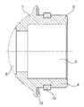
도 2는 연결 요소의 사시도이다.
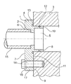
도 3은 도 1에 도시된 연결 요소의 밀봉 영역의 상세를 도시한다.
도 4는 파이프, 연결 요소, 및 공기 조절 시스템의 구성요소를 갖는 배치를 도시한다.DETAILED DESCRIPTION OF THE PREFERRED EMBODIMENTS Some embodiments of the present connection element are described in more detail below with reference to the drawings. In this schematic,
Figure 1 shows a cross section through a connecting element.
Figure 2 is a perspective view of the connecting element.
Fig. 3 shows details of the sealing area of the connecting element shown in Fig.
Figure 4 shows an arrangement with components of a pipe, a connecting element, and an air conditioning system.
도 1 내지 도 3은 공기 조절 시스템의 구성요소(3)에 파이프 단부(2)를 연결하기 위한 연결 요소(1)를 도시한다. 연결 요소(1)는 냉각제를 반송하기 위한 통과 개구(5) 및 파이프 단부(2)를 수용하기 위한 리셉터클 보어(6)를 갖는 베이스 본체(4)를 포함하며, 리셉터클 보어(6)는 베이스 본체(4)의 표측(7)에 배치되며 통과 보어(5)에 대응한다. 통과 보어(5) 및 리셉터클 보어(6)는 서로 동심으로 배치된다.Figures 1 to 3 show the connecting element 1 for connecting the
연결 요소(1)는 또한 베이스 본체(4)의 다른 표측(9)에 배치되며 이 표측에 마련된 통과 보어(5)에 대응하는 연결 피스(8)를 특징부로 하며, 연결 피스(8) 및 베이스 본체(4)는 동일한 재료로 구성되고 하나의 피스로 실현된다. 연결 피스(8) 및 통과 보어(5)는 서로 동심으로 배치된다. 연결 피스(8)는 파이프 섹션(10) 및 반경방향 플랜지(11)를 포함한다.The connecting element 1 is also arranged on the
2개의 밀봉 요소(12, 13)가 연결 피스(8)에 배치되며 연결 피스(8)와 일체로 실현된다. 이 경우, 제1 시일(12)이 파이프 섹션에 할당되며, 제2 시일이 반경방향 플랜지(13)에 할당된다.Two sealing
베이스 본체(4)는 구성요소(3)에 베이스 본체(4)를 체결하기 위한 체결 디바이스(14)를 구비한다.The
베이스 본체(4) 및 연결 피스(8)는 사출성형가능한 플라스틱으로 구성되며, 2개의 밀봉 요소(12, 13)는 사출성형가능한 엘라스토머로 구성된다. 밀봉 요소(12, 13)는 이 경우 연결 피스(8)에 일체로 연결된다.The
도 4는 파이프(15), 이 경우에는 폴리아미드의 플라스틱 파이프, 바람직하게는 압출된 다층 폴리아미드 파이프와 예를 들어 응축기 같은 공기 조절 시스템의 구성요소(3) 사이의 연결을 생성하는 상술한 연결 요소(1)를 갖는 배치를 도시한다.Figure 4 shows the connection of the
이 경우, 파이프(15)의 파이프 단부(2)는 연결 요소(1)의 베이스 본체(4)에 일체로 연결된다. 이 목적을 위해, 파이프(15)는 예를 들어 마찰 용접 또는 회전 마찰 용접에 의해 베이스 본체(4)에 고정될 수 있다.In this case, the
공기 조절 시스템의 구성요소(3)는 연결 요소(11)의 연결 피스(8)를 수용하기 위한 개구를 특징부로 한다. 각각의 밀봉 요소(12, 13)는 이 경우 구성요소의 외벽과 개구의 내벽에 치밀하게 인접한다. 연결 요소(1)는 체결 디바이스(14)에 의해 구성요소(3)에 강성적으로 연결된다. 체결 디바이스는 베이스 본체(4)의 돌출부(17)에 배치되는 추가적인 통과 보어(16)를 특징부로 한다. 체결 수단, 바람직하게는 스크류가 통과 보어(16)를 통해 삽입되며 구성요소(3)에 체결된다. 이 방식에서, 파이프(15)를 갖는 연결 요소(1)는 구성요소(3)에 신뢰가능하게 그리고 강성적으로 연결된다.The component (3) of the air conditioning system features an opening for receiving the connecting piece (8) of the connecting element (11). Each sealing
공기 조절 시스템의 구성요소(3)에 파이프 단부(2)를 연결하기 위한 연결 요소(1)를 제조하기 위한 본 발명 방법에서, 연결 피스(8)를 갖는 베이스 본체(4)를 제조하기 위한 사출성형가능한 플라스틱이 제1 단계에서 사출 성형 디바이스에 공급되고, 베이스 본체(4)에 일체로 형성된 적어도 하나의 밀봉 요소(12, 13)를 제조하기 위한 사출성형가능한 엘라스토머가 후속하여 사출 성형 디바이스로부터 베이스 본체(4)를 제거하기 전에 사출 성형 디바이스에 공급된다. 이에 의해 베이스 본체(4)에 일체로 형성된 밀봉 요소(12, 13)를 갖는 연결 요소(1)가 제조된다.In an inventive method for manufacturing a connecting element (1) for connecting a pipe end (2) to a component (3) of an air conditioning system, an injection for producing a base body (4) with a connecting piece (8) A moldable plastic is fed to the injection molding device in a first step and an injection moldable elastomer for producing at least one sealing element (12, 13) integrally formed in the base body (4) is subsequently introduced from the injection molding device Is supplied to the injection molding device before the
Claims (9)
연결 피스(8)는 파이프 섹션(10) 및 반경방향 플랜지(11)를 포함하는 것을 특징으로 하는 연결 요소.The method according to claim 1,
Characterized in that the connecting piece (8) comprises a pipe section (10) and a radial flange (11).
제1 시일(12)이 파이프 섹션(10)에 할당되는 것을 특징으로 하는 연결 요소.The method of claim 2,
Characterized in that a first seal (12) is assigned to the pipe section (10).
제2 시일(13)이 반경방향 플랜지(11)에 할당되는 것을 특징으로 하는 연결 요소.The method according to claim 2 or 3,
Characterized in that a second seal (13) is assigned to the radial flange (11).
베이스 본체(4)는 구성요소(3)에 베이스 본체(4)를 체결하기 위한 체결 디바이스(14)를 구비하는 것을 특징으로 하는 연결 요소.The method according to any one of claims 1 to 4,
Characterized in that the base body (4) comprises a fastening device (14) for fastening the base body (4) to the component (3).
파이프 단부(2)는 베이스 본체(4)에 일체로 연결되는 것을 특징으로 하는 연결 요소.The method according to any one of claims 1 to 5,
Characterized in that the pipe end (2) is integrally connected to the base body (4).
베이스 본체(4) 및 연결 피스(8)는 사출성형가능한 플라스틱으로 구성되는 것을 특징으로 하는 연결 요소.The method according to any one of claims 1 to 6,
Characterized in that the base body (4) and the connecting piece (8) are made of injection-moldable plastic.
적어도 하나의 밀봉 요소(12, 13)는 사출성형가능한 엘라스토머로 구성되는 것을 특징으로 하는 연결 요소.The method according to any one of claims 1 to 7,
Characterized in that the at least one sealing element (12, 13) comprises an injection-moldable elastomer.
적어도 하나의 밀봉 요소(12, 13)는 연결 피스(8)에 일체로 연결되는 것을 특징으로 하는 연결 요소.The method according to any one of claims 1 to 8,
Characterized in that at least one sealing element (12, 13) is integrally connected to the connecting piece (8).
Applications Claiming Priority (3)
| Application Number | Priority Date | Filing Date | Title |
|---|---|---|---|
| DE202015103455.5U DE202015103455U1 (en) | 2015-07-01 | 2015-07-01 | Connecting element for connecting a pipe end to a component of an air conditioning system |
| DE202015103455.5 | 2015-07-01 | ||
| PCT/EP2016/065435 WO2017001633A1 (en) | 2015-07-01 | 2016-06-30 | Connecting element for connecting a pipe end to a component of an air-conditioning system |
Publications (1)
| Publication Number | Publication Date |
|---|---|
| KR20180039637A true KR20180039637A (en) | 2018-04-18 |
Family
ID=53759354
Family Applications (1)
| Application Number | Title | Priority Date | Filing Date |
|---|---|---|---|
| KR1020187003154A KR20180039637A (en) | 2015-07-01 | 2016-06-30 | A connecting element for connecting the pipe end to the components of the air conditioning system |
Country Status (8)
| Country | Link |
|---|---|
| US (1) | US10876666B2 (en) |
| EP (1) | EP3317575B1 (en) |
| JP (1) | JP6799019B2 (en) |
| KR (1) | KR20180039637A (en) |
| CN (1) | CN108235719B (en) |
| DE (1) | DE202015103455U1 (en) |
| MX (1) | MX2018000247A (en) |
| WO (1) | WO2017001633A1 (en) |
Families Citing this family (8)
| Publication number | Priority date | Publication date | Assignee | Title |
|---|---|---|---|---|
| DE202016100195U1 (en) * | 2016-01-15 | 2016-02-01 | Ti Automotive Engineering Centre (Heidelberg) Gmbh | Connecting arrangement for an air conditioner |
| FR3054613B1 (en) * | 2016-07-29 | 2020-04-10 | Sogefi Air & Refroidissement France | INTAKE DISTRIBUTOR WITH INTEGRATED HEAT EXCHANGER |
| DE102018102927A1 (en) * | 2018-02-09 | 2019-08-14 | Voss Automotive Gmbh | Fluid distribution module for a modular temperature control system and temperature control system |
| CN111758233B (en) * | 2018-02-26 | 2023-06-02 | 瑞典爱立信有限公司 | Prioritization of scheduling requests and ACK/NACK |
| EP3632718A1 (en) * | 2018-10-02 | 2020-04-08 | Nitto Belgium N.V | Hvac sealing member, vehicles comprising the same and related methods and uses |
| CN111113791B (en) * | 2019-12-31 | 2022-05-06 | 浙江新龙实业有限公司 | Air conditioner pipeline flange assembly machining process |
| KR20210125669A (en) * | 2020-04-09 | 2021-10-19 | 현대자동차주식회사 | Piping system for air conditioner |
| KR20230007866A (en) * | 2021-07-06 | 2023-01-13 | 현대자동차주식회사 | Nipple assembly |
Family Cites Families (31)
| Publication number | Priority date | Publication date | Assignee | Title |
|---|---|---|---|---|
| US2461414A (en) * | 1945-06-15 | 1949-02-08 | Curtiss Wright Corp | Fitting for transparent tubes |
| JPS5639378A (en) * | 1979-09-06 | 1981-04-15 | Hart & Co Pty S W | Socket joint for enameled container |
| US4569540A (en) * | 1983-12-29 | 1986-02-11 | Beson Technology, Inc. | Piping suspender with metal-to-metal seal |
| ZA85151B (en) | 1984-01-25 | 1985-08-28 | Squibb & Sons Inc | Quick disconnect tube coupling |
| US4907651A (en) * | 1987-12-21 | 1990-03-13 | Texaco Inc. | Metal-to-metal packer seal for downhole disconnectable pipe joint |
| FR2678052B1 (en) * | 1991-06-19 | 1993-09-24 | Valeo Thermique Moteur Sa | DEVICE FOR FIXING TWO TUBING ON TWO NEIGHBORHOOD OPENINGS OF A HEAT EXCHANGER HOUSING. |
| DE4441348A1 (en) * | 1994-11-21 | 1996-05-23 | Basf Ag | Connection of flange at end of pipe to flat counter=part esp. for plastics pipes |
| JPH09210264A (en) * | 1996-02-01 | 1997-08-12 | Kunimori Kagaku:Kk | Pipe joint |
| JPH11325362A (en) * | 1998-05-13 | 1999-11-26 | Smc Corp | Pipe joint |
| US6443502B1 (en) | 1999-04-22 | 2002-09-03 | Denso Corporation | Leakage restriction device for refrigeration cycle |
| JP2001004251A (en) | 1999-04-22 | 2001-01-12 | Denso Corp | Leak-proof device for refrigerating machine |
| US6890005B1 (en) * | 1999-10-29 | 2005-05-10 | Hutchinson Fts, Inc. | Self-centering tubular connection |
| US6386593B1 (en) * | 1999-10-29 | 2002-05-14 | Automotive Fluid Systems, Inc. | Dual-plane seal for fluid-tight conduit connection |
| DE10163931A1 (en) | 2001-12-22 | 2003-07-03 | Obrist Engineering Gmbh Lusten | Pipe coupling has coupling block formed by connector encompassed by O-ring, and socket to receive connector, with the O-ring bearing against conical edge face of connector socket |
| US6676167B2 (en) * | 2002-05-20 | 2004-01-13 | Visteon Global Technologies, Inc. | Air conditioning block fitting with two surface sealing |
| DE10240441B3 (en) * | 2002-09-02 | 2004-01-15 | Siemens Ag | Connection arrangement for a fluid line, in particular a leakage connection of a fuel injector |
| EP1445046A1 (en) * | 2003-02-07 | 2004-08-11 | Vesuvius Crucible Company | Means for connecting a pipe for circulating a fluid to a refractory article and refractory article |
| JP4096832B2 (en) * | 2003-07-22 | 2008-06-04 | 株式会社デンソー | Piping joint for refrigeration cycle |
| DE102005001301A1 (en) * | 2005-01-04 | 2006-07-13 | Hansgrohe Ag | Shower head has connector nipple to fit into opening in wall and with attachment to water feed pipe |
| JP2007107585A (en) | 2005-10-12 | 2007-04-26 | Calsonic Kansei Corp | High-pressure piping joint |
| JP4675742B2 (en) * | 2005-10-14 | 2011-04-27 | 株式会社クボタ | Mounting structure of hydraulic joint |
| US7766391B2 (en) * | 2006-04-05 | 2010-08-03 | Doowon Climate Control Co., Ltd. | Pipe connecting structure |
| DE102006033357B4 (en) * | 2006-07-19 | 2009-04-09 | Elringklinger Ag | A device for forming a sealed fitting for the connection of a pipeline to an outlet for a thermally stressing flow medium |
| JP2008101788A (en) | 2006-10-17 | 2008-05-01 | Showa Denko Kk | Piping joint for refrigerating cycle |
| JP2009000840A (en) * | 2007-06-19 | 2009-01-08 | Showa Corp | Method for producing joint of fluidic device |
| US20110163540A1 (en) * | 2007-11-02 | 2011-07-07 | Entegris, Inc. | O-ringless seal couplings |
| JP2009127809A (en) * | 2007-11-27 | 2009-06-11 | Gomuno Inaki Kk | Pipe joint part structure |
| JP5805492B2 (en) | 2011-10-11 | 2015-11-04 | サンデンホールディングス株式会社 | Piping connection structure |
| CN202708380U (en) * | 2012-06-08 | 2013-01-30 | 钱法君 | Metal injection loose joint |
| DE102013005806A1 (en) * | 2013-04-04 | 2014-10-09 | Modine Manufacturing Co. | Nozzle connection for heat exchangers |
| DE102018120464B4 (en) * | 2017-09-19 | 2022-06-30 | Hanon Systems | Arrangement for fluid-tight connection of lines |
-
2015
- 2015-07-01 DE DE202015103455.5U patent/DE202015103455U1/en active Active
-
2016
- 2016-06-30 US US15/740,584 patent/US10876666B2/en active Active
- 2016-06-30 KR KR1020187003154A patent/KR20180039637A/en not_active Application Discontinuation
- 2016-06-30 EP EP16735621.1A patent/EP3317575B1/en active Active
- 2016-06-30 JP JP2017568454A patent/JP6799019B2/en active Active
- 2016-06-30 MX MX2018000247A patent/MX2018000247A/en unknown
- 2016-06-30 WO PCT/EP2016/065435 patent/WO2017001633A1/en active Application Filing
- 2016-06-30 CN CN201680039257.5A patent/CN108235719B/en active Active
Also Published As
| Publication number | Publication date |
|---|---|
| JP6799019B2 (en) | 2020-12-09 |
| DE202015103455U1 (en) | 2015-07-14 |
| US10876666B2 (en) | 2020-12-29 |
| MX2018000247A (en) | 2018-05-22 |
| CN108235719A (en) | 2018-06-29 |
| JP2018520319A (en) | 2018-07-26 |
| EP3317575B1 (en) | 2019-03-27 |
| EP3317575A1 (en) | 2018-05-09 |
| CN108235719B (en) | 2019-11-05 |
| US20180187814A1 (en) | 2018-07-05 |
| WO2017001633A1 (en) | 2017-01-05 |
Similar Documents
| Publication | Publication Date | Title |
|---|---|---|
| KR20180039637A (en) | A connecting element for connecting the pipe end to the components of the air conditioning system | |
| US10661488B2 (en) | Air duct cuff and method of manufacture | |
| US10563802B2 (en) | Device for hose fitting | |
| US20070113912A1 (en) | Tube for guiding gas or liquid | |
| CN102099219A (en) | Motor vehicle fuel tank | |
| US20110233927A1 (en) | Coupling Element | |
| CN100402911C (en) | Piping unit for transporting fuel | |
| US20210088166A1 (en) | Method of making an inline housing for a part enclosed in a tube | |
| KR101960553B1 (en) | Modular fitting | |
| CN110892186B (en) | Fluid pipeline | |
| US11428358B2 (en) | Fluid interaction device, fluid interaction arrangement and method for producing same | |
| US7316427B2 (en) | Hollow plastic product having a connector pipe | |
| WO2014093785A1 (en) | Access port plug | |
| US9709195B2 (en) | Conduit for an air induction system including a flexible sealing cuff and related method | |
| KR101432945B1 (en) | Pipe connecting apparatus of one-touch type | |
| JP5010294B2 (en) | Sealing structure of through-holes formed in the wall of plastic hollow molding | |
| KR101591943B1 (en) | Connecting structure of pipe and block for air conditioning system | |
| KR102531851B1 (en) | Structure of connection between duct and flexible hose | |
| US20210025522A1 (en) | Flangeless coupler fused inside opposing ends of conduits | |
| KR20190133510A (en) | Intake hose for vehicle and method for manufacturing of the intake hose | |
| JP2014066275A (en) | Hose connection structure |
Legal Events
| Date | Code | Title | Description |
|---|---|---|---|
| E902 | Notification of reason for refusal | ||
| E601 | Decision to refuse application |