KR20180021733A - Method and apparatus for determining prediction of current block of enhancement layer - Google Patents
Method and apparatus for determining prediction of current block of enhancement layer Download PDFInfo
- Publication number
- KR20180021733A KR20180021733A KR1020177037683A KR20177037683A KR20180021733A KR 20180021733 A KR20180021733 A KR 20180021733A KR 1020177037683 A KR1020177037683 A KR 1020177037683A KR 20177037683 A KR20177037683 A KR 20177037683A KR 20180021733 A KR20180021733 A KR 20180021733A
- Authority
- KR
- South Korea
- Prior art keywords
- block
- patch
- prediction
- base layer
- enhancement layer
- Prior art date
Links
Images


Classifications
-
- H—ELECTRICITY
- H04—ELECTRIC COMMUNICATION TECHNIQUE
- H04N—PICTORIAL COMMUNICATION, e.g. TELEVISION
- H04N19/00—Methods or arrangements for coding, decoding, compressing or decompressing digital video signals
- H04N19/30—Methods or arrangements for coding, decoding, compressing or decompressing digital video signals using hierarchical techniques, e.g. scalability
- H04N19/33—Methods or arrangements for coding, decoding, compressing or decompressing digital video signals using hierarchical techniques, e.g. scalability in the spatial domain
-
- H—ELECTRICITY
- H04—ELECTRIC COMMUNICATION TECHNIQUE
- H04N—PICTORIAL COMMUNICATION, e.g. TELEVISION
- H04N19/00—Methods or arrangements for coding, decoding, compressing or decompressing digital video signals
- H04N19/10—Methods or arrangements for coding, decoding, compressing or decompressing digital video signals using adaptive coding
- H04N19/102—Methods or arrangements for coding, decoding, compressing or decompressing digital video signals using adaptive coding characterised by the element, parameter or selection affected or controlled by the adaptive coding
- H04N19/103—Selection of coding mode or of prediction mode
- H04N19/11—Selection of coding mode or of prediction mode among a plurality of spatial predictive coding modes
-
- H—ELECTRICITY
- H04—ELECTRIC COMMUNICATION TECHNIQUE
- H04N—PICTORIAL COMMUNICATION, e.g. TELEVISION
- H04N19/00—Methods or arrangements for coding, decoding, compressing or decompressing digital video signals
- H04N19/10—Methods or arrangements for coding, decoding, compressing or decompressing digital video signals using adaptive coding
- H04N19/134—Methods or arrangements for coding, decoding, compressing or decompressing digital video signals using adaptive coding characterised by the element, parameter or criterion affecting or controlling the adaptive coding
- H04N19/157—Assigned coding mode, i.e. the coding mode being predefined or preselected to be further used for selection of another element or parameter
-
- H—ELECTRICITY
- H04—ELECTRIC COMMUNICATION TECHNIQUE
- H04N—PICTORIAL COMMUNICATION, e.g. TELEVISION
- H04N19/00—Methods or arrangements for coding, decoding, compressing or decompressing digital video signals
- H04N19/10—Methods or arrangements for coding, decoding, compressing or decompressing digital video signals using adaptive coding
- H04N19/169—Methods or arrangements for coding, decoding, compressing or decompressing digital video signals using adaptive coding characterised by the coding unit, i.e. the structural portion or semantic portion of the video signal being the object or the subject of the adaptive coding
- H04N19/17—Methods or arrangements for coding, decoding, compressing or decompressing digital video signals using adaptive coding characterised by the coding unit, i.e. the structural portion or semantic portion of the video signal being the object or the subject of the adaptive coding the unit being an image region, e.g. an object
- H04N19/176—Methods or arrangements for coding, decoding, compressing or decompressing digital video signals using adaptive coding characterised by the coding unit, i.e. the structural portion or semantic portion of the video signal being the object or the subject of the adaptive coding the unit being an image region, e.g. an object the region being a block, e.g. a macroblock
-
- H—ELECTRICITY
- H04—ELECTRIC COMMUNICATION TECHNIQUE
- H04N—PICTORIAL COMMUNICATION, e.g. TELEVISION
- H04N19/00—Methods or arrangements for coding, decoding, compressing or decompressing digital video signals
- H04N19/30—Methods or arrangements for coding, decoding, compressing or decompressing digital video signals using hierarchical techniques, e.g. scalability
- H04N19/36—Scalability techniques involving formatting the layers as a function of picture distortion after decoding, e.g. signal-to-noise [SNR] scalability
-
- H—ELECTRICITY
- H04—ELECTRIC COMMUNICATION TECHNIQUE
- H04N—PICTORIAL COMMUNICATION, e.g. TELEVISION
- H04N19/00—Methods or arrangements for coding, decoding, compressing or decompressing digital video signals
- H04N19/50—Methods or arrangements for coding, decoding, compressing or decompressing digital video signals using predictive coding
- H04N19/593—Methods or arrangements for coding, decoding, compressing or decompressing digital video signals using predictive coding involving spatial prediction techniques
-
- H—ELECTRICITY
- H04—ELECTRIC COMMUNICATION TECHNIQUE
- H04N—PICTORIAL COMMUNICATION, e.g. TELEVISION
- H04N19/00—Methods or arrangements for coding, decoding, compressing or decompressing digital video signals
- H04N19/60—Methods or arrangements for coding, decoding, compressing or decompressing digital video signals using transform coding
- H04N19/61—Methods or arrangements for coding, decoding, compressing or decompressing digital video signals using transform coding in combination with predictive coding
Abstract
방법이 개시되며, 여기서 방법은, 동적 범위가 낮은(LDR) 제 1 중간 패치를 구축하는 단계(S715); 동적 범위가 높은(HDR) 제 2 중간 패치를 구축하는 단계(S725); 변환 영역에서 기저 계층의 변환된 초기 패치에 전달 함수를 적용한 다음에 픽셀 영역에서 복귀하도록 결과적인 패치에 역 변환을 적용함으로써, 패치를 구축하는 단계(S735); 패치로부터 블록을 추출함으로써 강화 계층의 현재 블록의 예측을 예측하는 단계(S740); 그리고 강화 계층의 현재 블록과 강화 계층의 현재 블록의 예측 간의 잔류 오차를 인코딩하는 단계를 포함한다.A method is disclosed, wherein the method includes constructing a first intermediate patch of low dynamic range (LDR) (S715); Constructing a second intermediate patch having a high dynamic range (HDR) (S725); Constructing a patch (S735) by applying a transfer function to the transformed initial patch of the base layer in the transform region and then applying an inverse transform to the resulting patch to return in the pixel region; Estimating a prediction of a current block of the enhancement layer by extracting a block from the patch (S740); And encoding the residual error between the current block of the enhancement layer and the prediction of the current block of the enhancement layer.

Description
본 개시내용은 강화 계층(enhancement layer)의 현재 블록(current block)의 예측(prediction)을 결정하기 위한 방법 및 장치에 관한 것이다.The present disclosure relates to a method and apparatus for determining a prediction of a current block of an enhancement layer.
이미지 프로세싱(image processing) 분야에서, 톤 맵핑 연산자(Tone Mapping Operators)(이것은 이하에서 "TMO"로 지칭될 수 있음)가 알려져 있다. 자연 환경 내의 실제 물체(objects)를 이미지화(imaging)할 때, 이러한 실제 물체의 동적 범위(dynamic range)는 카메라와 같은 이미지화 디바이스(imaging devices)가 이미지화할 수 있거나 혹은 디스플레이(displays)가 디스플레이할 수 있는 동적 범위보다 훨씬 더 높다. 실제 물체를 이러한 디스플레이 상에서 자연스럽게 디스플레이하기 위해서, TMO는 양호한 가시 상태(visible conditions)를 유지하면서 동적 범위가 높은(High Dynamic Range)(이것은 이하에서 "HDR"로 지칭될 수 있음) 이미지를 동적 범위가 낮은(Low Dynamic Range)(이것은 이하에서 "LDR"로 지칭될 수 있음) 이미지로 변환하는데 사용된다.In the field of image processing, Tone Mapping Operators (which may be referred to below as "TMO ") are known. When imaging real objects in a natural environment, the dynamic range of such an actual object can be imaged by imaging devices such as a camera or displayed Which is much higher than the dynamic range. In order to naturally display an actual object on such a display, the TMO has a dynamic range of high dynamic range (which may be referred to as "HDR" hereinafter) while maintaining good visible conditions And is used to convert a low dynamic range (which may be referred to as "LDR" hereinafter) images.
일반적으로 말해서, TMO는 LDR 이미지가 획득되도록 HDR 신호에 직접 적용되고, 이러한 이미지는 기존의 LDR 디스플레이 상에서 디스플레이될 수 있다. 매우 다양한 TMO들이 존재하고, 이들 중 많은 TMO들은 비-선형 연산자(non-linear operators)이다.Generally speaking, the TMO is applied directly to the HDR signal so that the LDR image is acquired, and this image can be displayed on the existing LDR display. There are a wide variety of TMOs, many of which are non-linear operators.
LDR/HDR 비디오 압축에 관한 기술(art)과 관련하여, 논문(저자: Z. Mai, H. Mansour, R. Mantiuk, P. Nasiopoulos, R. Ward 및 W. Heidrich, 제목: "On-the-fly tone mapping for backward-compatible high dynamic range image/video compression", ISCAS, 2010)에서 설명되는 바와 같이 하나의 가능한 것으로서 전체적(global) TMO/iTMO(inverse Tone Mapping Operations, 역 톤 맵핑 연산자)를 사용하는 것이 제안되고 있다.With regard to the art of LDR / HDR video compression (art), the paper (author: Z. Mai, H. Mansour, R. Mantiuk, P. Nasiopoulos, R. Ward and W. Heidrich, entitled "On- (TMO) / iTMO (Inverse Tone Mapping Operations) as one possible, as described in " fly tone mapping for backward-compatible high dynamic range image / video compression ", ISCAS, 2010 Have been proposed.
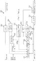
이러한 논문에서는, 부동 소수점 데이터(floating point data)의 분포가 전체 양자화 오차(quantization error)의 최소화를 위해 고려된다. 알고리즘은 다음과 같은 단계들에 의해 설명된다(여기서 사용되는 변수들은 도 1에 예시됨).In this paper, the distribution of floating point data is considered for minimizing the overall quantization error. The algorithm is illustrated by the following steps (the variables used here are illustrated in FIG. 1).
단계 1(Step 1): 루미넌스(luminance) 값들의 로그(logarithm)가 계산된다. 따라서, 루민넌스 L의 각각의 픽셀(pixel)에 대해, 다음과 같은 단계들은 값 l=log10(L)에 기반을 두고 있다. (l은 여전히 부동 소수점 형식(floating point format)을 갖는다.)Step 1: The logarithm of the luminance values is calculated. Thus, for each pixel of the ruminance L, the following steps are based on the value l = log 10 (L). (l still has a floating point format.)
단계 2(Step 2): l 값들의 히스토그램(histogram)이 δ=0,1에 고정된 빈 크기(bin size)를 고려함으로써 계산된다. 예를 들어, 이미지 시퀀스(image sequence) 내의 모든 픽셀들이 히스토그램을 구축(build)하는데 사용될 수 있다. 따라서, 각각의 빈 k(k=1..N)에 대해, 픽셀이 이러한 빈에 속할 확률 pk가 알려져 있다. 값 lk = δ.k가 빈에 할당된다.Step 2: The histogram of the l values is calculated by taking into account the bin size fixed at δ = 0,1. For example, all pixels in an image sequence can be used to build a histogram. Thus, it is for each bin k (k = 1..N), the pixel is known that the probability p k belongs to this bin. Value l k = δ.k is assigned to the blank.
단계 3(Step 3): 기울기 값(slope value)이 다음과 같은 수식(formula) (1)에 의해 설명되는 모델(model)로부터 각각의 빈 K에 대해 계산된다:Step 3: The slope value is calculated for each bin K from the model described by the formula (1)

여기서 vmax는 고려되는 정수 표현(integer representation)의 최대 값이다(만약 데이터가 n 비트 정수들로 양자화된다면, vmax = 2n-1).Where v max is the maximum value of the integer representation considered (v max = 2 n -1 if the data is quantized with n bit integers).
역 방정식(inversion equation)(역 톤 맵핑 5.)에서 제로(zero)에 의한 나눗셈의 위험을 피하기 위해, 만약 sk=0이라면, sk는 대신 널(null)이 아닌 최소 값 ε에서 설정될 수 있다.To avoid the risk of division by zero in the inversion equation (
단계 4(Step 4): N개의 기울기 값들을 알고 있는 경우, 전체적 톤 맵핑 곡선(global tone mapping curve)이 정의될 수 있다. [1,N] 내의 각각의 k에 대해, lk<l<=lk+1을 충족시키는 부동 소수점 수 l이, 다음과 같은 수식 (2)에 의해 정의되는 정수 값 v에 맵핑된다:Step 4: If the N slope values are known, a global tone mapping curve may be defined. For each k in [1, N], a floating-point number l that satisfies lk <l <= l k + 1 is mapped to an integer value v defined by the following equation (2)
![]()
![]()
여기서 값 vk는 vk+1 = δ.sk + vk (및 v1=0)에 의해 값 sk로부터 정의된다.Where the value v k is defined from the value s k by v k + 1 =? S k + v k (and v 1 = 0).
그 다음에, 값 v는 구간(interval) [0, 2n-1] 내의 정수를 획득하기 위해 반올림(round)된다.The value v is then rounded to obtain an integer in the interval [0, 2 n -1].
단계 5(Step 5): 역 톤 맵핑을 수행하기 위해, 파라미터(parameters) sk(k=1..N)는 디코더(decoder)로 전송돼야만 한다. 톤 맵핑된 이미지 내의 값 v의 주어진 픽셀에 대해, 먼저, vk<=v<vk+1을 충족시키는 값 k가 발견돼야만 한다.Step 5: To perform reverse tone mapping, the parameters s k (k = 1..N) must be transmitted to the decoder. For a given pixel value of v in the image tone mapping, the first dwaeyaman, v k <= v <v k is the value found to meet the k + 1.
그 다음에, 역 방정식이 다음과 같은 수식 (3)으로서 표현된다:Next, the inverse equation is expressed as Equation (3)
![]()
![]()
여기서, 디코딩된 픽셀 값(decoded pixel value)이 ![]()
![]()
더욱이, 역 톤 맵핑(iTMO)을 적용하기 위해, 디코더는 도 1에서의 곡선을 알아야만 한다.Moreover, in order to apply the reverse tone mapping (iTMO), the decoder must know the curve in Fig.
본 명세서에서의 용어 "디코딩된(decoded)"은 비디오 코더/디코더(video coder/decoder)의 용어 "디코딩된(decoded)"과는 다른 역-양자화 연산(de-quantization operation)에 대응한다.The term "decoded " in this context corresponds to a de-quantization operation different from the term" decoded "of a video coder / decoder.
또 하나의 다른 가능한 것은 논문(저자: M. Grundland 외, 제목: "Non linear multiresolution blending", Machine Graphis & vision International Journal Volume 15 Issue 3 Feb 2006, 그리고 저자: Zhe Wendy Wang; Jiefu Zhai; Tao Zhang; Llach, Joan, 제목: "Interactive tone mapping for High Dynamic Range video". ICASSP 2010)에서 개시되는 바와 같이 국지적 톤 맵핑 연산자(local tone mapping operators)를 사용하는 것이다. 예를 들어, TMO 라플라시안 피라미드(laplacian pyramid)가 공개문헌(저자: Peter J. Burt, Edward H. Adelson, 제목: "The Laplacian Pyramid as a compact image code", IEEE Transactions on Communications, vol. COM-3l, no. 4, April 1983, 그리고 저자: Burt P.J., 제목: "The Pyramid as Structure for Efficient Computation. Multiresolution Image Processing and Analysis", Springer-Verlag, 6-35, 그리고 발명자: Zhai jiedu, Joan Llach, 발명의 명칭: "Zone-based tone mapping" WO 2011/002505 A1)에 근거하여 사용될 수 있다. TMO의 효율(efficiency)은 HDR 이미지로부터 상이한 중간 LDR 이미지들을 추출하는 것에 있는데, 여기서 중간 LDR 이미지들은 상이한 노출(exposures)에 대응한다. 따라서, 과다-노출된 LDR 이미지(over-exposed LDR image)는 어두운 영역(dark regions)에서 세밀한 묘사(fine details)를 포함하는 반면 (본래의 HDR 이미지의) 밝은 영역(lighting regions)은 포화(saturate)된다. 이와는 대조적으로, 과소-노출된 LDR 이미지(under-exposed LDR image)는 밝은 구역에서 세밀한 묘사를 포함하는 반면 어두운 영역은 클리핑(clipping)된다.Another possible work is the work of M. Grundland et al., Titled "Nonlinear multiresolution blending", Machine Graphis & Vision International Journal Volume 15
이후, 각각의 LDR 이미지는 n개의 레벨들의 라플라시안 피라미드에서 분해되고, 가장 높은 레벨은 가장 낮은 해상도(resolution)에 전용으로 제공되고(dedicated), 다른 레벨들은 (그래디언트(gradient)의) 다른 스펙트럼 밴드(spectral bands)를 제공한다. 따라서, 이러한 단계에서, 각각의 LDR 이미지는 라플라시안 피라미드에 대응하고, 또한 우리가 알 수 있는 것은 반올림 오산(rounding miscalculation)이 존재하지 않는 경우에만 각각의 LDR 이미지가 역 분해(inverse decomposition) 혹은 "붕괴(collapse)"를 사용함으로써 자신의 라플라시안 피라미드로부터 재구축(rebuilt)될 수 있다는 것이다.Each LDR image is then decomposed in a laplacian pyramid of n levels, with the highest level being dedicated to the lowest resolution and the other levels being assigned to different spectral bands (gradients) spectral bands. Thus, at this stage, each LDR image corresponds to a Laplacian pyramid, and what we can also see is that each LDR image is inversely decomposed or "collapsed" only if there is no rounding miscalculation can be rebuilt from his own Laplacian pyramid by using "collapse".
마지막으로, 톤 맵핑은 중간 LDR 이미지들의 세트(set)의 상이한 피라미드 레벨들의 결합(fusion)으로 구현되고, 그 결과적인 융합된 피라미드(blended pyramid)는 최종 LDR 이미지를 제공하도록 붕괴된다.Finally, the tone mapping is implemented with the fusion of different pyramidal levels of the set of intermediate LDR images, and the resulting blended pyramid is collapsed to provide the final LDR image.
사실, 상이한 스펙트럼 밴드들(혹은 피라미드 레벨들)의 그래디언트들의 결합은 비-선형 프로세스(non-linear process)이다. 이러한 타입의 알고리즘의 이점은 톤 맵핑의 효율적인 결과에 있지만, 때때로 후광 아티팩트(halo artifacts)와 같은 다수의 잘-알려진 렌더링 결함(rendering fault)이 야기된다. 앞서의 참조문헌들은 이러한 기법에 관한 더 세부적 내용들을 제공한다.In fact, the combination of the gradients of the different spectral bands (or pyramid levels) is a non-linear process. The advantage of this type of algorithm is the efficient result of tone mapping, but sometimes causes a number of well-known rendering faults, such as halo artifacts. The foregoing references provide more detail on these techniques.
실제로, 이러한 톤 맵핑이 비-선형이기 때문에, SNR(Signal-to-Noise Ratio, 신호-대-노이즈 비) 또는 공간적 비디오 확장가능성(spatial video scalability)과 관련하여 HDR 계층(HDR layer)의 현재 블록에 허용가능한 예측을 제공하도록 LDR의 역 톤 맵핑을 구현하는 것은 어렵다.Indeed, since this tone mapping is non-linear, the current block of the HDR layer (HDR layer) in relation to signal-to-noise ratio (SNR) or spatial video scalability It is difficult to implement the reverse tone mapping of the LDR to provide an acceptable prediction for the LDR.
더욱이, 국제공개문헌 WO2010/018137은 참조 이미지(reference image)의 참조 블록(reference block)을 수정하기 위한 방법; 참조 블록으로부터 도움(help)을 받아 이미지의 블록을 인코딩(encoding) 혹은 디코딩(decoding)하기 위한 방법 및 이를 위한 디바이스; 그리고 수정된 참조 블록으로부터 도움을 받아 인코딩된 블록을 보유하는 저장 매체 혹은 신호를 개시한다. 종래 기술에서, 전달 함수(transfer function)는 이웃하는 평균 값(neighboring mean values)으로부터 추정(estimate)되고, 그리고 이러한 함수는 인터-이미지 예측(inter-image prediction)을 정정(correct)하는데 사용된다. 하지만, 국제공개문헌 WO2010/018137에서, 이러한 접근법은 현재 블록 및 병치된(collocated) 블록의 제 1 근사화(approximation)를 제공하기 위해 평균 값(mean value)에 한정된다.Furthermore, WO2010 / 018137 discloses a method for modifying a reference block of a reference image; A method and a device for encoding or decoding a block of an image by receiving help from a reference block; And starts the storage medium or signal holding the encoded block with assistance from the modified reference block. In the prior art, the transfer function is estimated from neighboring mean values, and this function is used to correct inter-image prediction. However, in the international publication WO2010 / 018137, this approach is limited to a mean value to provide a first approximation of the current block and the collocated block.
본 개시내용의 실시예에 따르면, 방법이 제공되며, 이러한 방법은, 기저 계층(base layer)의 병치된 블록(collocated block)의 이웃하는 픽셀(neighboring pixel)들을 가짐과 아울러, 기저 계층의 병치된 블록의 이웃하는 픽셀들로부터 기저 계층의 코딩 모드(coding mode)를 이용해 예측된 제 1 예측 블록(prediction block)을 갖는, 동적 범위가 낮은(Low Dynamic Range, LDR) 제 1 중간 패치(intermediate patch)를 구축(building)하는 단계; 강화 계층(enhancement layer)의 현재 블록(current block)의 이웃하는 픽셀들을 가짐과 아울러, 강화 계층의 현재 블록의 이웃하는 픽셀들로부터 코딩 모드를 이용해 예측된 제 2 예측 블록을 갖는, 동적 범위가 높은(High Dynamic Range, HDR) 제 2 중간 패치를 구축하는 단계; 변환 영역(transform domain)에서 기저 계층의 변환된 초기 패치에 전달 함수(transfer function)를 적용한 다음에 픽셀 영역(pixel domain)에서 복귀(return)하도록 결과적인 패치에 역 변환(inverse transform)을 적용함으로써, 패치(patch)를 구축하는 단계(여기서, 전달 함수는 변환 영역에서 제 1 중간 패치를 제 2 중간 패치로 변환하도록 결정됨); 패치로부터 블록을 추출함으로써 강화 계층의 현재 블록의 예측(prediction)을 예측하는 단계(여기서, 패치 내의 추출된 블록은 제 2 중간 패치 내의 강화 계층의 현재 블록에 병치(collocate)됨); 그리고 강화 계층의 현재 블록과 강화 계층의 현재 블록의 예측 간의 잔류 오차(residual error)를 인코딩(encoding)하는 단계를 포함한다.According to an embodiment of the present disclosure, a method is provided that includes neighboring pixels of a collocated block of a base layer, as well as neighboring pixels of a collocated block of a base layer, A low dynamic range (LDR) first intermediate patch having a first prediction block predicted using a coding mode of a base layer from neighboring pixels of the block, Building; Having a second prediction block predicted using a coding mode from neighboring pixels of a current block of a current block of the enhancement layer and having neighboring pixels of a current block of an enhancement layer, (HDR) second intermediate patch; By applying an inverse transform to the resulting patch to apply a transfer function to the transformed initial patch of the base layer in the transform domain and then return from the pixel domain , Constructing a patch (wherein the transfer function is determined to convert the first intermediate patch to the second intermediate patch in the transform region); Predicting a prediction of a current block of the enhancement layer by extracting a block from the patch, wherein the extracted blocks in the patch are collocated with the current block of the enhancement layer in the second intermediate patch; And encoding a residual error between the current block of the enhancement layer and the prediction of the current block of the enhancement layer.
본 개시내용의 실시예에 따르면, 장치가 제공되며, 이러한 장치는, 제 1 중간 패치 생성 유닛(first intermediate patch creation unit); 제 2 중간 패치 생성 유닛; 하나의 유닛; 그리고 인코더(encoder)를 포함하며, 여기서 제 1 중간 패치 생성 유닛은, 기저 계층의 병치된 블록의 이웃하는 픽셀들로부터 기저 계층의 코딩 모드를 이용해 제 1 예측 블록을 예측하는 것; 그리고 기저 계층의 병치된 블록의 이웃하는 픽셀들을 가짐과 아울러, 제 1 예측 블록을 갖는, 동적 범위가 낮은(LDR) 제 1 중간 패치를 구축하는 것을 수행하도록 구성되고, 그리고 제 2 중간 패치 생성 유닛은, 강화 계층의 현재 블록의 이웃하는 픽셀들로부터 코딩 모드를 이용해 제 2 예측 블록을 예측하는 것; 그리고 강화 계층의 현재 블록의 이웃하는 픽셀들을 가짐과 아울러, 제 2 예측 블록을 갖는, 동적 범위가 높은(HDR) 제 2 중간 패치를 구축하는 것을 수행하도록 구성되고, 그리고 하나의 유닛은, 변환 영역에서 제 1 중간 패치를 제 2 중간 패치로 변환하기 위한 전달 함수를 결정하는 것; 변환 영역에서 기저 계층의 변환된 초기 패치에 전달 함수를 적용한 다음에 픽셀 영역에서 복귀하도록 결과적인 패치에 역 변환을 적용함으로써, 패치를 구축하는 것; 그리고 패치로부터 블록을 추출함으로써 강화 계층의 현재 블록의 예측을 예측하는 것을 수행하기 위한 유닛이고(여기서, 추출된 블록은 패치 내에서 제 2 중간 패치 내의 강화 계층의 현재 블록에 병치됨), 그리고 인코더는, 강화 계층의 현재 블록과 강화 계층의 현재 블록의 예측 간의 잔류 오차를 인코딩하기 위한 인코더이다.According to an embodiment of the present disclosure, an apparatus is provided, comprising: a first intermediate patch creation unit; A second intermediate patch generation unit; One unit; And an encoder, wherein the first intermediate patch generation unit comprises: predicting a first prediction block using the coding mode of the base layer from neighboring pixels of the collocated block of the base layer; And constructing a low dynamic range low first order (LDR) intermediate patch having a first predicted block and neighboring pixels of the collocated block of the base layer, and the second intermediate patch generation unit Predicting a second prediction block using a coding mode from neighboring pixels of a current block of the enhancement layer; And to construct a second high dynamic range (HDR) intermediate patch having a neighboring pixels of the current block in the enhancement layer and a second prediction block, Determining a transfer function for converting a first intermediate patch to a second intermediate patch at a second intermediate patch; Applying a transfer function to the transformed initial patch of the base layer in the transform region and then applying the inverse transform to the resulting patch to return in the pixel region; And extracting a block from the patch to predict the prediction of the current block of the enhancement layer, wherein the extracted block is juxtaposed to the current block of the enhancement layer in the second intermediate patch in the patch, Is an encoder for encoding the residual error between the current block of the enhancement layer and the prediction of the current block of the enhancement layer.
본 개시내용의 또 하나의 다른 실시예에 따르면, 방법이 제공되며, 이러한 방법은, 잔류 예측 오차(residual prediction error)를 디코딩하는 단계; 기저 계층의 병치된 블록의 이웃하는 픽셀들을 가짐과 아울러, 기저 계층의 병치된 블록의 이웃하는 픽셀들로부터 기저 계층의 코딩 모드를 이용해 예측된 제 1 예측 블록을 갖는, 동적 범위가 낮은(LDR) 제 1 중간 패치를 구축하는 단계; 강화 계층의 현재 블록의 이웃하는 픽셀들을 가짐과 아울러, 강화 계층의 현재 블록의 이웃하는 픽셀들로부터 코딩 모드를 이용해 예측된 제 2 예측 블록을 갖는, 동적 범위가 높은(HDR) 제 2 중간 패치를 구축하는 단계; 변환 영역에서 기저 계층의 변환된 초기 패치에 전달 함수를 적용한 다음에 픽셀 영역에서 복귀하도록 결과적인 패치에 역 변환을 적용함으로써, 패치를 구축하는 단계(여기서, 전달 함수는 변환 영역에서 제 1 중간 패치를 제 2 중간 패치로 변환하게 됨); 패치로부터 블록을 추출함으로써 강화 계층의 현재 블록의 예측을 예측하는 단계(여기서, 패치 내의 추출된 블록은 제 2 중간 패치 내의 강화 계층의 현재 블록에 병치됨); 그리고 강화 계층의 현재 블록의 예측에 예측 오차를 더함(adding)으로써 강화 계층의 블록을 재구성(reconstructing)하는 단계를 포함한다.According to yet another embodiment of the present disclosure, a method is provided, comprising the steps of: decoding a residual prediction error; (LDR) block having neighboring pixels of a juxtaposed block of a base layer and having a first prediction block predicted from neighboring pixels of a juxtaposed block of a base layer using a coding mode of a base layer, Constructing a first intermediate patch; (HDR) second intermediate patch having a neighboring pixels of the current block of the enhancement layer and having a second prediction block predicted from the neighboring pixels of the current block of the enhancement layer using a coding mode, Building; Constructing a patch by applying a transfer function to the transformed initial patch of the base layer in the transform region and then applying an inverse transform to the resulting patch to return in the pixel region, wherein the transfer function comprises: To a second intermediate patch); Predicting a prediction of a current block of the enhancement layer by extracting a block from the patch, wherein the extracted blocks in the patch are juxtaposed to the current block of the enhancement layer in the second intermediate patch; And reconstructing a block of the enhancement layer by adding a prediction error to the prediction of the current block of the enhancement layer.
본 개시내용의 또 하나의 다른 실시예에 따르면, 장치가 제공되며, 이러한 장치는, 잔류 예측 오차를 디코딩하기 위한 디코더(decoder); 제 1 중간 패치 생성 유닛; 제 2 중간 패치 생성 유닛; 하나의 유닛; 그리고 또 하나의 유닛을 포함하며, 여기서 제 1 중간 패치 생성 유닛은, 기저 계층의 병치된 블록의 이웃하는 픽셀들을 가짐과 아울러, 기저 계층의 병치된 블록의 이웃하는 픽셀들로부터 기저 계층의 코딩 모드를 이용해 예측된 제 1 예측 블록을 갖는, 동적 범위가 낮은(LDR) 제 1 중간 패치를 구축하도록 구성되고, 그리고 제 2 중간 패치 생성 유닛은, 강화 계층의 현재 블록의 이웃하는 픽셀들을 가짐과 아울러, 강화 계층의 현재 블록의 이웃하는 픽셀들로부터 코딩 모드를 이용해 예측된 제 2 예측 블록을 갖는, 동적 범위가 높은(HDR) 제 2 중간 패치를 구축하도록 구성되고, 그리고 하나의 유닛은, 변환 영역에서 기저 계층의 변환된 초기 패치에 전달 함수를 적용한 다음에 픽셀 영역에서 복귀하도록 결과적인 패치에 역 변환을 적용함으로써, 패치를 구축하기 위한 유닛이고(여기서, 전달 함수는 변환 영역에서 제 1 중간 패치를 제 2 중간 패치로 변환하게 됨), 그리고 하나의 유닛은 또한, 패치로부터 블록을 추출함으로써 강화 계층의 현재 블록의 예측을 예측하기 위한 유닛이고(여기서, 추출된 블록은 패치 내에서 제 2 중간 패치 내의 강화 계층의 현재 블록에 병치됨), 그리고 또 하나의 유닛은, 강화 계층의 블록을 재구성하기 위해 강화 계층의 현재 블록의 예측에 예측 오차를 더하기 위한 유닛이다.According to yet another embodiment of the present disclosure, an apparatus is provided, comprising: a decoder for decoding a residual prediction error; A first intermediate patch generation unit; A second intermediate patch generation unit; One unit; And wherein the first intermediate patch generating unit has neighboring pixels of a juxtaposed block of the base layer and at least one of the neighboring pixels of the base layer's neighboring pixels of the juxtaposed block of the base layer, (LDR) first intermediate patch having a predicted first prediction block using the second intermediate patch generation unit, and the second intermediate patch generation unit is configured to have a neighboring pixels of the current block of the enhancement layer, (HDR) second intermediate patch having a second predicted block predicted using a coding mode from neighboring pixels of a current block of the enhancement layer, and one unit is configured to construct a second intermediate patch, By applying a transfer function to the transformed initial patch of the base layer and then applying the inverse transform to the resulting patch to return from the pixel region, (Where the transfer function converts the first intermediate patch to the second intermediate patch in the transform domain), and one unit also predicts the prediction of the current block of the enhancement layer by extracting the block from the patch (Where the extracted block is bound to the current block of the enhancement layer in the second intermediate patch in the patch), and another unit is used to reconstruct a block of the enhancement layer It is a unit to add prediction error to prediction.
본 개시내용의 다른 목적, 특징, 및 이점은 첨부 도면들과 함께 읽혀지는 경우 다음의 상세한 설명으로부터 더 명백하게 될 것이다.Other objects, features, and advantages of the present disclosure will become more apparent from the following detailed description when read in conjunction with the accompanying drawings.
도 1은 부동 소수점 값 l=log10(L)의 히스토그램, 그리고 기울기 sk에 근거하는 그 관련된 톤 맵핑 곡선이다.
도 2a 및 도 2b는 인코딩될, 재구성된 기저 계층의 이미지 및 강화 계층의 현재 블록의 이미지이다.
도 3a는 내지 도 3j는 H.264 표준에서 특정된 인트라 4x4 예측(Intra 4x4 prediction)의 예를 나타내는 도면들이다.
도 4a 내지 도 4b는 제 1 실시예에 따른 강화 계층의 현재 블록의 예측을 결정하기 위한 장치를 예시하는 블록도들이고, 여기서 도 4a는 인코더 측(encoder side)이고 도 4b는 디코더 측(decoder side)이다.
도 5a 내지 도 5b는 본 개시내용의 실시예의 제 2 실시예의 강화 계층의 현재 블록의 예측을 결정하기 위한 장치의 구성을 예시하는 블록도들이고, 여기서 도 5a는 인코더 측이고 도 5b는 디코더 측이다.
도 6은 본 개시내용의 제 4 실시예의 강화 계층의 현재 블록의 예측을 결정하기 위한 장치의 구성을 예시하는 블록도이다.
도 7은 본 개시내용의 실시예에 따른 강화 계층의 현재 블록의 예측을 결정하기 위한 예시적인 방법을 나타내는 흐름도이다.1 is a histogram of the floating point value l = log 10 (L), and its associated tone mapping curve based on the slope s k .
Figures 2a and 2b are images of the reconstructed base layer and the current block of enhancement layers to be encoded.
3A to 3J are diagrams showing examples of Intra 4x4 prediction specified in the H.264 standard.
Figures 4A-4B are block diagrams illustrating an apparatus for determining a prediction of a current block of a enhancement layer in accordance with the first embodiment, wherein Figure 4A is an encoder side and Figure 4B is a decoder side )to be.
Figures 5A-5B are block diagrams illustrating a configuration of an apparatus for determining a prediction of a current block of a enhancement layer in a second embodiment of an embodiment of the present disclosure, wherein Figure 5A is an encoder side and Figure 5B is a decoder side .
6 is a block diagram illustrating a configuration of an apparatus for determining a prediction of a current block of a enhancement layer in a fourth embodiment of the present disclosure;
7 is a flow diagram illustrating an exemplary method for determining a prediction of a current block of enhancement layers in accordance with an embodiment of the present disclosure.
본 개시내용의 실시예들에 관한 설명이 도면들을 참조하여 아래에서 제공된다.A description of embodiments of the present disclosure is provided below with reference to the drawings.
본 개시내용의 실시예들은, 전체적 혹은 국지적 (비-선형) 방식으로 사용되는 역 톤 맵핑 연산자(inverse Tone Mapping Operations)(이것은 이하에서 "iTMO"로 지칭될 수 있음) 및 이전의 TMO의 프로세싱을 향상시키는 것을 목표로 한다(명백한 것으로, 기저 계층 신호가 여전히 사용가능한 경우임).Embodiments of the present disclosure may include inverse Tone Mapping Operations (which may be referred to below as "iTMO") and previous TMO processing used in an overall or local (non-linear) manner (Obviously, if the base layer signal is still available).
본 발명의 개념(idea)은 예를 들어, LDR 비디오 인코딩에 전용으로 제공되는 주어진 TMO를 사용하는 제 1 톤 맵핑된 기저 계층 ![]()
![]()
![]()
![]()
![]()
![]()
![]()
![]()
블록 ![]()
![]()
![]()
![]()
![]()
![]()
![]()
![]()
![]()
![]()
![]()
![]()
![]()
![]()
![]()
![]()
![]()
![]()
![]()
![]()
![]()
![]()
![]()
![]()
![]()
![]()
![]()
![]()
![]()
![]()
![]()
![]()
![]()
![]()
여기서, 변환 ![]()
![]()
![]()
![]()
![]()
![]()
앞에서 설명된 전체 프로세싱 단계들은 또한 인코더 측(encoder side)에서뿐만 아니라 디코더 측(decoder side)에서도 구현됨을 아는 것이 또한 중요하다.It is also important to know that the entire processing steps described above are also implemented on the decoder side as well as on the encoder side.
[원리(Principle)][Principle]
본 개시내용의 실시예에서 제안되는 접근법을 예시하기 위해, SNR 확장가능성에 기반을 둔 예가 아래에서 제공된다. 이러한 경우(SNR 확장가능성의 경우)에, 강화 계층의 (인코딩될) 현재 블록 ![]()
![]()
![]()
![]()
도 2a 및 도 2b는 개별적으로 인코딩될, 재구성된 기저 계층의 이미지 그리고 현재 블록의 이미지를 예시한다.Figures 2A and 2B illustrate an image of the reconstructed base layer and an image of the current block to be encoded separately.
도 2b에 예시된 표기는, 강화 계층 ![]()
![]()
![]()
![]()
![]()
![]()
![]()
![]()
![]()
![]()
![]()

![]()
![]()
![]()
도 2a에 예시된 표기는, 기저 계층 ![]()
![]()
![]()
![]()
![]()
![]()
![]()
![]()
![]()
![]()
![]()
![]()

목표는 블록 ![]()
![]()
![]()
![]()
명백한 것으로, 비디오 압축의 맥락에서, 블록 ![]()
![]()
![]()
![]()
![]()
![]()
![]()
![]()
이후, 블록 ![]()
![]()
![]()
![]()
![]()
![]()
[제 1 실시예(First Embodiment)][First Embodiment]
도 3a 내지 도 3j 그리고 도 4를 참조하여, 강화 계층의 현재 블록의 예측을 결정하기 위한 방법 및 장치의 제 1 실시예에 관한 설명이 제공된다.Referring to Figures 3A-3J and 4, a description of a first embodiment of a method and apparatus for determining a prediction of a current block of enhancement layers is provided.
더 구체적으로, 본 개시내용의 제 1 실시예는 SNR 확장가능성에 대한 것인데, 즉, LDR 기저 계층과 HDR 강화 계층들 간의 동일한 공간적 해상도(spatial resolution)에 대한 것이다. 추가적으로, 제 1 실시예에서, 현재 블록 ![]()
![]()
![]()
![]()
블록 ![]()
![]()
![]()
![]()
![]()
![]()
도 3a 내지 도 3j는 H.264 표준에서 특정된 인트라 4x4 예측들을 예시하는 도면들이다. 도 3a 내지 도 3j에서 예시되는 바와 같이, N(여기서, H264의 경우 N=9)개의 서로 다른 인트라 모드 예측들이 H.264 표준에서 제공된다.3A-3J are diagrams illustrating intra 4x4 predictions specified in the H.264 standard. As illustrated in Figures 3A-3J, N (where N = 9 for H264) different intra mode predictions are provided in the H.264 standard.
H.264에서, 인트라 4x4 및 인트라 8x8 예측들은 이웃하는 재구성된 픽셀들에 근거하여 코딩될 현재 블록의 픽셀들의 공간적 추정(spatial estimation)에 대응한다. H.264 표준은 픽셀 예측의 정교화(elaborate)를 위해 상이한 방향성 예측 모드(directional prediction mode)들을 특정한다. 아홉(9) 개의 인트라 예측 모드들이 매크로블록(MacroBlock, MB)의 4x4 및 8x8 블록 크기에 관해 정의된다. 도 3에서 도시되는 바와 같이, 이러한 모드들 중 여덟(8) 개는 예측할 현재 블록을 둘러싸는 (좌측 열(left column) 및 상단 라인(top line)으로부터의) 픽셀들의 1D 방향성 외삽(directional extrapolation)으로 구성된다. 인트라 예측 모드 2(DC 모드)는 예측된 블록 픽셀들을 이용가능한 주변 픽셀들의 평균(average)으로서 정의한다.In H.264, intra 4x4 and intra 8x8 predictions correspond to a spatial estimation of the pixels of the current block to be coded based on neighboring reconstructed pixels. The H.264 standard specifies different directional prediction modes for elaborating pixel prediction. Nine (9) intra prediction modes are defined for 4x4 and 8x8 block sizes of a macroblock (MB). As shown in FIG. 3, eight (8) of these modes include 1D directional extrapolation of pixels (from the left column and top line) surrounding the current block to be predicted, . Intra prediction mode 2 (DC mode) defines predicted block pixels as the average of the available neighboring pixels.
인트라 4x4의 예에서, 예측들은 도 3a 내지 도 3j에서 예시되는 바와 같이 구축된다.In the example of the intra 4x4, the predictions are constructed as illustrated in Figures 3a-3j.
예를 들어, 도 3c에서 예시되는 바와 같이, 모드 1(수평(horizontal))에서, 픽셀들 e, f, g, 및 h는 (좌측 열에 있는) 재구성된 픽셀 J를 이용해 예측된다.For example, in mode 1 (horizontal), pixels e, f, g, and h are predicted using reconstructed pixel J (in the left column), as illustrated in Figure 3C.
더욱이, 도 3g에서 예시되는 바와 같이, 모드 5에서, 제 1 예로서, "a"는 (Q+A+1)/2에 의해 예측된다. 유사하게, 제 2 예로서, "g" 및 "p"는 (A+2B+C+2)/4에 의해 예측된다.Furthermore, as illustrated in FIG. 3G, in
여기서, 앞서 논의된 문제로 돌아가서, 예측의 블록: ![]()
![]()
![]()
![]()
![]()
![]()
여기서, 두 개의 중간 패치들 X' 및 Y'은 다음과 같은 수식 (6) 및 수식 (7)로서 구성될 수 있다.Here, the two intermediate patches X 'and Y' can be constructed as the following equations (6) and (7).
현재 중간 패치 X':Currently the intermediate patch X ':

기저 계층의 중간 패치 Y':Middle patch of base layer Y ':

원하는 변환 ![]()
![]()
![]()
![]()
![]()
![]()
수식 TF (Y')는 패치 Y'의 2D 변환 "TF"(예를 들어, DCT)에 대응한다.The equation TF (Y ') corresponds to the 2D transform "TF" (e.g., DCT) of patch Y'.
다음 단계는 ![]()
![]()
![]()
![]()
![]()
![]()

여기서, u 및 v는 ![]()
![]()
![]()
![]()
![]()
![]()
함수 Trf는 기저 계층의 초기 패치 Y의 변환(TF)에 적용되고, 이것은 역 변환(TF-1) 이후에 패치 Y''를 제공한다. 패치 Y''는 수식 (12) 내지 수식 (14)에 의해 보여지는 바와 같이 템플릿 ![]()
![]()
![]()
![]()

여기서, ![]()
![]()
그리고, ![]()
![]()
수식 ![]()
![]()
![]()
![]()
![]()
![]()
![]()
![]()
최종적으로, 현재 블록 ![]()
![]()
![]()
![]()
![]()
![]()
도 4a 내지 도 4b는 제 1 실시예의 강화 계층의 현재 블록의 예측을 결정하기 위한 장치를 예시하는 블록도들이다. 인트라 SNR 확장가능성에 관한 본 설명의 원리가 또한, 도 4a 및 도 4b에서 예시된다.Figures 4A-4B are block diagrams illustrating an apparatus for determining a prediction of a current block of a enhancement layer of the first embodiment. The principles of this description of intra SNR extensibility are also illustrated in Figures 4A and 4B.
도 4a 및 도 4b를 참조하여, 국지적 인터-계층 LDR HDR 예측(Local inter-layer LDR HDR prediction)이 설명된다.Referring to Figures 4A and 4B, local inter-layer LDR prediction (Local Inter-layer LDR HDR prediction) is described.
설명을 명확하게 하기 위해, 특히 디코더에 관한 설명을 명확하게 하기 위해, 우리는 SNR 확장가능 비디오 코딩(Scalable Video Coding, SVC) 방식을 설명한다:To clarify the description, and in particular to clarify the description of the decoder, we describe the SNR scalable video coding (SVC) scheme:
(1) 1차적으로 기저 계층(1) a base layer
(2) 그리고 2차적으로 강화 계층(2) and, secondarily,
도 4a에서 보여지는 인코더(혹은 코더) 측에서, 그리고 도 4b에서 보여지는 디코더 측에서, 알아야 하는 것은 제안(proposal)이 인터 계층(bl->el) 예측에 초점이 맞추어져 있다는 것이다.On the encoder (or coder) side as shown in FIG. 4A and on the decoder side as shown in FIG. 4B, it is to be noted that the proposal is focused on inter-layer (bl-> el) prediction.
코더 측 및 디코더 측에서는 인트라 모드(m)를 사용하는 인트라 이미지 예측 모드만이 설명되는데, 왜냐하면 우리의 인터 계층 예측 모드는 인트라 모드(m)를 사용하기 때문이다. 따라서, (주어진 RDO(Rate Distortion Optimizations, 레이트 왜곡 최적화) 기준을 사용하는) 예측 유닛의 기능이 아래와 같은 (1) 및 (2)로부터 최상의 예측 모드를 결정하는 것에 있다는 것은 잘 알려져 있다:On the coder side and the decoder side, only an intra-image prediction mode using the intra mode (m) is described, because our intra-layer prediction mode uses the intra mode (m). It is therefore well known that the function of the prediction unit (using a given Rate Distortion Optimizations (RDO) criterion) lies in determining the best prediction mode from (1) and (2) below:
(1) 기저 계층 레벨에서의 인트라 및 인터 이미지 예측들(1) Intra and inter-image predictions at the base layer level
(2) 강화 계층 레벨에서의 인트라, 인터 이미지 및 인터 계층 예측들(우리의 새로운 예측 모드)(2) Intra, inter-image and inter-layer predictions at enhanced layer level (our new prediction mode)
인덱스의 의미(Signification of the index): Signification of the index :
k: 알려짐(known)k: known
u: 알려지지 않음(unknown)u: unknown
B: 블록(block)B: block
T: (비디오 압축 영역에서 일반적으로 "템플릿(Template)"으로 지칭되는) 블록의 이웃(neighbor)T: neighbor of a block (generally referred to as a "template" in the video compression domain)
Pred: 예측(prediction)Pred: prediction
m: N개의 이용가능한 모드들로부터의 인트라 코딩 모드의 인덱스m: the index of the intra coding mode from the N available modes
Y, X, Y', X', 및 Y''는 도 2a 및 도 2b와 관련하여 블록 및 템플릿으로 구성된 패치들이다.Y, X, Y ', X', and Y '' are patches configured as blocks and templates with reference to FIGS. 2A and 2B.
도 4a에서의 코더 측(Coder side)(유닛(400)):Coder side (unit 400) in FIG. 4A:
본래의 블록(401) ![]()
![]()
![]()
![]()
기저 계층(Base layer)Base layer (bl)(bl)
우리는 인코딩할 본래의 기저 계층 블록 ![]()
![]()
a) 본래의 블록 ![]()
![]()
b) 만약 모드 결정 프로세스(mode decision process)(유닛(425))가 (N개의 인트라 이용가능 모드들로부터 m 인덱스의) 인트라 이미지 예측 모드를 선택한다면, 본래의 블록 bbc와 예측 블록 ![]()
![]()
c) 이후, 잔류 오차 예측 rb는 T Q 유닛(422)에 의해 rbq로 변환 및 양자화되며, 최종적으로 엔트로피 코더 유닛(entropy coder unit)(423)에 의해 엔트로피 코딩(entropy coding)되고 비트스트림 기저 계층(bitstream base layer)에서 전송된다.c), the residual error prediction rb is transformed and quantized to r bq by the
d) T-1 Q-1 유닛(424)에 의해 역 변환된 그리고 역양자화된 예측 오차 블록(prediction error block) rbdq를 (결합기(427)를 이용해) 예측 블록 ![]()
![]()
e) 재구성된(혹은 디코딩된) 프레임은 (bl) 참조 프레임들 버퍼(426)에 저장된다.e) The reconstructed (or decoded) frame is stored in (bl)
강화 계층(Enhancement layer)Enhancement layer (el)(el)
우리는 강화 계층의 코더의 구조가 기저 계층의 코더와 유사하다는 것을 알 수 있는데, 예를 들어, 코딩 모드 결정, 시간적 예측 및 참조 프레임들 버퍼에 관하여, 유닛들(407, 408, 409 및 413)은 기저 계층의 코더의 각각의 유닛들(425, 426, 429 및 430)과 동일한 기능을 갖는다. 우리는 이제 인코딩할 본래의 강화 계층 블록 ![]()
![]()
f) 강화 계층의 블록에 대해, 만약 기저 계층의 병치된 블록이 인트라 이미지 모드에서 코딩된다면, 우리는 이러한 병치된 블록의 (m 인덱스의) 인트라 모드를 고려한다(도 7에서 보여지는 방법(700)의 S705).f) For a block in the enhancement layer, if the juxtaposed block of the base layer is coded in intra-image mode, we consider the intra mode of this juxtaposed block (at the index m) ).
g) 기저 계층의 (m 인덱스의) 이러한 인트라 모드를 이용해, 우리가 결정하는 것은 다음과 같다:g) Using this intra mode (at the m-index) of the base layer, we determine:
![]()
![]()
![]()
![]()
![]()
![]()
![]()
![]()
![]()
![]()
![]()
![]()
h) 유사하게, 기저 계층의 (m 인덱스의) 이러한 인트라 모드를 이용해, 우리가 결정하는 것은 다음과 같다:h) Similarly, using this intra mode (of the index m) of the base layer, we decide:
![]()
![]()
![]()
![]()
![]()
![]()
![]()
![]()
![]()
![]()
![]()
![]()
i) 변환 영역(예를 들어, DCT)에서, 우리는 수식 (8) 내지 수식 (11)을 사용해 패치 Y'로부터 패치 X'로의 전달 함수 Trf를 결정한다(도 7의 S730).i) In the transform domain (e.g., DCT), we determine the transfer function Trf from patch Y 'to patch X' using equation (8) to equation (11) (S730 in FIG. 7).
j) 이제 우리는 병치된 블록(![]()
![]()
![]()
![]()
1. 우리는 패치 Y에 변환(예를 들어, DCT)을 적용함: ![]()
![]()
2. Trf 함수가 이제 변환 영역에서 적용됨, 예를 들어: ![]()
![]()
3. 역 변환(예를 들어, DCT-1)이 ![]()
![]()
![]()
![]()
4. 최종적으로, 블록 ![]()
![]()
f로부터 j까지의 모든 단계들은 도 4a에서 "Pred el/bl (Trf)" 유닛(411)에서 실현된다.All the steps from f to j are realized in the "Pred el / bl (Trf)"
k) 단계 f 내지 단계 j에서 계산되는 (결합기(402)를 사용하는) 강화 계층 블록 ![]()
![]()
![]()
![]()
![]()
![]()
l) 최종적으로, T-1 Q-1 유닛(405)에 의해 역 변환된 그리고 역양자화된 예측 오차 블록 redq를 (결합기(410)를 이용해) 예측 ![]()
![]()
도 4b에서의 디코더 측(Decoder side)(유닛(450)):Decoder side (unit 450) in Figure 4b:
기저 계층(Base layer)Base layer (bl)(bl)
a) bl 비트스트림으로부터, 주어진 블록에 대해, 엔트로피 디코더(entropy decoder)(엔트로피 디코더 유닛(entropy decoder unit))(471)는 양자화된 오차 예측 rbq 및 m 인덱스의 관련된 코딩 인트라 모드를 디코딩함From a bl bitstream, for a given block, an entropy decoder (entropy decoder unit) 471 decodes the associated coding intra mode of quantized error prediction r bq and m indexes
b) 잔류 오차 예측 rbq는 T-1 Q-1 유닛(472)에 의해 rbdq로 역양자화 및 역 변환됨,b) Residual error prediction r bq is dequantized and inverse transformed to r bdq by T -1 Q -1 unit 472,
c) m 인트라 모드로부터의 도움을 받아, "공간적 예측(Sp Pred)" 유닛(475) 및 "예측" 유닛(474)은 디코딩된 이웃하는 픽셀을 이용해 인트라-이미지 예측의 블록 ![]()
![]()
![]()
![]()
d) 디코딩된 그리고 역양자화된 예측 오차 블록 rbdq를 (결합기(473)를 이용해) 예측 블록 ![]()
![]()
![]()
![]()
e) 재구성된(혹은 디코딩된) 프레임은 참조 프레임들 버퍼(476)에 저장되고, 디코딩된 프레임들은 (모션 보상 유닛(motion compensation unit)(477)을 사용해) 다음 (bl) 인트라 이미지 예측 및 인터 예측을 위해 사용된다.e) reconstructed (or decoded) frames are stored in the
강화 계층(Enhancement layer)Enhancement layer (el)(el)
f) el 비트스트림으로부터, 주어진 블록에 대해, 엔트로피 디코더(451)는 양자화된 오차 예측 req를 디코딩한다.From the f) el bitstream, for a given block, the
g) 잔류 오차 예측 req는 T-1 Q-1 유닛(452)에 의해 역양자화 및 역 변환되고, redq가 출력된다.g) Residual error prediction r eq is dequantized and inverse transformed by T -1 Q -1 unit 452, and r edq is output.
h) 만약 디코딩할 블록의 코딩 모드가 우리의 인터-계층 모드에 대응한다면, 우리는 기저 계층의 병치된 블록의 (m 인덱스의) 인트라 모드를 고려한다.h) If the coding mode of the block to be decoded corresponds to our inter-layer mode, we consider the intra mode of the (m-indexed) block of the collocated block of the base layer.
i) 기저 계층의 (m 인덱스의) 이러한 인트라 모드를 이용해, 우리가 결정하는 것은 다음과 같다:i) Using this intra mode (at the m-index) of the base layer, we determine:
![]()
![]()
![]()
![]()
![]()
![]()
![]()
![]()
![]()
![]()
![]()
![]()
j) 유사하게, 기저 계층의 (m 인덱스의) 이러한 인트라 모드를 이용해, 우리가 결정하는 것은 다음과 같다:j) Similarly, using this intra mode (at the index m) of the base layer, we determine:
![]()
![]()
![]()
![]()
![]()
![]()
![]()
![]()
![]()
![]()
![]()
![]()
k) 변환 영역(예를 들어, DCT)에서, 우리는 수식 (8) 내지 수식 (11)을 사용해 패치 Y'로부터 패치 X'로의 전달 함수 Trf를 결정한다.k) In the transform domain (e.g., DCT), we use the equation (8) to equation (11) to determine the transfer function Trf from patch Y 'to patch X'.
l) 이제 우리는 병치된 블록(![]()
![]()
![]()
![]()
1. 우리는 패치 Y에 변환(예를 들어, DCT)을 적용함: ![]()
![]()
2. Trf 함수가 이제 변환 영역에서 적용됨, 예를 들어: ![]()
![]()
3. 역 변환(예를 들어, DCT-1)이 ![]()
![]()
![]()
![]()
![]()
![]()
4. 최종적으로, 블록 ![]()
![]()
h로부터 l까지의 모든 단계들은 "Pred el/bl (Trf)" 유닛(457)에서 실현되고, 우리는 단계 h 내지 단계 l이 (제 1 실시예의) 코더의 단계 f 내지 단계 j와 정확히(strictly) 동일하다는 것을 알 수 있다; 명백한 것으로 el 코더가 el 코더(407)의 모드 결정에 의해 이러한 인터-계층 예측 모드를 선택한 경우임.all the steps from h to l are realized in the " Pred el / bl (Trf) "
m) 디코딩된 그리고 역양자화된 예측 오차 블록 redq를 (결합기(453)를 이용해) (예측 유닛(454)을 통한) 예측 블록 ![]()
![]()
n) 재구성된(혹은 디코딩된) 이미지는 (el) 참조 프레임들 버퍼(456)에 저장되고, 디코딩된 프레임들은 (모션 보상 유닛(458)을 사용해) 다음 (el) 인트라 이미지 예측 및 인터 예측을 위해 사용됨n) reconstructed (or decoded) image is stored in the (el)
앞에서 설명되는 바와 같이, 제 1 실시예의 장치는 도 4a 및 도 4b에 의해 예시되는 바와 같이 구성될 수 있고, 이러한 장치에 의해 제 1 실시예의 방법이 수행될 수 있다.As described above, the apparatus of the first embodiment can be configured as exemplified by Figs. 4A and 4B, and the method of the first embodiment can be performed by such apparatus.
강화 계층의 현재 블록의 예측을 결정하기 위한 방법 및 장치에 따르면, 기저 계층의 병치된 블록의 코딩 모드를 이용함으로써, 강화 계층의 현재 블록의 예측이 쉽고 정확하게 획득될 수 있다.According to the method and apparatus for determining the prediction of the current block of the enhancement layer, prediction of the current block of enhancement layer can be easily and accurately obtained by using the coding mode of the juxtaposed block of the base layer.
[제 2 실시예(Second Embodiment)][Second Embodiment]
제 1 실시예에서, 기저 계층의 예측의 인트라 모드는 현재 블록 및 병치된 블록들의 제 1 근사화를 가질 목적으로 사용될 수 있고, 그리고 다음 단계들은 수식 (8) 내지 수식 (14)와 함께 상세히 설명된 알고리즘에 대응한다.In the first embodiment, the intra mode of the prediction of the base layer may be used for the purpose of having a first approximation of the current block and the blocks juxtaposed, and the following steps may be performed using the equation (8) Algorithm.
제 2 실시예에서는, 기저 계층과 강화 계층을 인코딩하기 위해 사용되는 인코더 알고리즘들이 서로 다른 그러한 더 복잡한 상황에 관한 설명이 아래에서 제공되며, 이에 따라 예측의 모드들은 호환가능(compatible)하지 않다. 간단한 예는, (예를 들어, 기술문헌(The JPEG-2000 Still Image Compression Standard, ISO/IEC JTC Standard, 1/SC29/WG1, 2005, 그리고 Jasper Software Reference Manual (Version 1.900.0), ISO/IEC JTC, Standard 1/SC29/WG1, 2005)에서 설명되는) JPEG2000을 이용해 인코딩되는 기저 계층, 그리고 H.264를 이용해 인코딩되는 강화 계층에 대응할 수 있다. 이러한 상황에서, 제 1 실시예는 적용가능하지 않은데, 왜냐하면 m 인트라 모드는 (예를 들어, JPEG2000) 기저 계층에서 이용가능하지 않기 때문이다.In the second embodiment, a description of such a more complex situation in which the encoder algorithms used to encode the base layer and enhancement layer are provided below, and thus the modes of prediction are not compatible. A simple example is described in ISO / IEC JTC Standard, 1 / SC29 / WG1, 2005, and Jasper Software Reference Manual (Version 1.900.0) JTC,
이러한 문제를 해결하기 위해서, (강화 계층의 인코더에서 이용가능한) 예측의 모드들을 테스트(testing)하는 것이, 그러한 디코딩되는 픽셀들이 명백하게 이용가능한지를 점검(check)하기 위해 기저 계층의 픽셀들에 관해 수행되고, 최종적으로 최상의 인트라 모드가, 주어진 기준에 따라, 선택된다.To solve this problem, testing the modes of prediction (available in the enhancement layer's encoder) is performed on the pixels of the base layer to check whether such decoded pixels are explicitly available And finally, the best intra mode is selected according to a given criterion.
강화 계층 및 기저 계층의 현재 패치 및 병치된 패치는 다음과 같은 수식 (16) 및 수식 (17)에 의해 제시된다.The current patches and juxtaposed patches of the enhancement layer and the base layer are presented by the following equations (16) and (17).
현재 패치는: 
(X의 병치된) 병치된 패치는:The juxtaposed patch (in X's juxtaposition) is:

(m 인덱스의) 최상의 인트라 모드를 선택하는 것은, n개의 가능한 인트라 모드들(예를 들어, 도 3에서 보여지는 모드들에 대응하는 것들)의 세트 S={m0, ..., mn -1}로부터 실현된다. 이러한 목적을 위해, 가상 예측 오차(virtual prediction error)가, j 인덱스의 주어진 모드에 따라 (병치된 블록 ![]()
![]()
![]()
![]()
![]()
![]()
![]()
![]()
![]()
![]()
![]()
![]()
여기서, ![]()
![]()
![]()
![]()
![]()
![]()
![]()
![]()
![]()
![]()
![]()
![]()
최상의 가상 예측 모드는 n개의 이용가능한 인트라 모드들 예측으로부터 가상 예측 오차의 최소치에 의해 다음과 같은 수식 (19)로서 제공된다.The best virtual prediction mode is provided as the following equation (19) by the minimum of the virtual prediction error from the prediction of the n available intra modes.
![]()
![]()
여기서, 수식 (18)에 의해 가상 예측 오차를 계산하기 위해 사용되는 계량법(metric)은 제곱 오차의 합(Sum of Square Error, SSE)으로 한정되는 것이 아니며, 다른 계량법들: 절대 차이의 합(Sum of Absolute Difference, SAD), 절대 하다마르 변환 차이의 합(Sum of Absolute Hadamard Transform Difference, SATD)이 가능함에 유의해야 한다.Here, the metric used to calculate the virtual prediction error according to Equation (18) is not limited to the Sum of Square Error (SSE), and other metrics: sum of absolute differences (Sum of Absolute Difference (SAD), and Sum of Absolute Hadamard Transform Difference (SATD).
병치된 블록 ![]()
![]()
![]()
![]()
![]()
![]()
![]()
![]()
![]()
![]()
새로운 중간 패치들이 다음과 같은 수식 (20) 및 수식 (21)로서 제공된다.New intermediate patches are provided as Equations (20) and (21) below.
현재 중간 패치 X':Currently the intermediate patch X ':

기저 계층의 중간 패치 Y':Middle patch of base layer Y ':

이제, 중간 가상 예측 블록들 ![]()
![]()
![]()
![]()
![]()
![]()
전달 함수 ![]()
![]()

수식 (22)에서, 현재 블록의 예측은 ![]()
![]()
인트라 SNR 확장가능성의 이러한 설명의 원리가 도 5a 및 도 5b에서 예시된다. 도 5는 본 개시내용의 제 2 실시예의 강화 계층의 현재 블록의 예측을 결정하기 위한 장치의 구성을 예시하는 블록도이다.The principle of this description of intra SNR extensibility is illustrated in Figures 5A and 5B. 5 is a block diagram illustrating a configuration of an apparatus for determining a prediction of a current block of a enhancement layer of a second embodiment of the present disclosure.
도 5a에서의 코더 측(Coder side)(유닛(500)):Coder side (unit 500) in Fig. 5A:
블록 ![]()
![]()
기저 계층(Base layer)Base layer (bl)(bl)
우리는 인코딩할 본래의 기저 계층 이미지 imbl을 고려한다. 주어진 비디오 인코더(531)를 갖는 경우, 이미지는 코더(531)를 이용해 인코딩되고, 그리고 국지적 인-루프 디코더(local in-loop decoder)(532)에 의해 국지적으로 디코딩된다. 국지적으로 디코딩된 이미지들은 "재구성된 이미지들 버퍼(reconstructed images buffer)"(533)에 저장된다. 결과적인 인코딩된 이미지들은 기저 계층 비트스트림에서 전송된다.We consider the original base layer image im bl to encode. With a given
강화 계층(Enhancement layer)Enhancement layer (el)(el)
우리는 이제 인코딩할 본래의 강화 계층 블록 ![]()
![]()
a) 강화 계층의 현재 블록에 대해, 우리는 (m 인덱스의) 강화 계층 인코더 인트라 모드의 이용가능한 모든 인트라 코딩 모드들을 고려함,a) For the current block of the enhancement layer, we consider all available intra-coding modes of the enhancement layer encoder intra mode (of index m)
![]()
![]()
b) 강화 계층의 (Jmode 인덱스의) 이러한 인트라 모드를 이용해, 우리가 결정하는 것은 다음과 같다:b) Using this intra mode of the enhancement layer (of the Jmode index), we determine:
![]()
![]()
![]()
![]()
![]()
![]()
![]()
![]()
![]()
![]()
![]()
![]()
c) 유사하게, 기저 계층의 (Jmode 인덱스의) 이러한 인트라 모드를 이용해, 우리가 결정하는 것은 다음과 같다:c) Similarly, using this intra mode of the base layer (of the Jmode index), we decide:
![]()
![]()
![]()
![]()
![]()
![]()
![]()
![]()
![]()
![]()
![]()
![]()
d) 변환 영역(예를 들어, DCT)에서, 우리는 수식 (8) 내지 수식 (11)을 사용해 패치 Y'로부터 패치 X'로의 전달 함수 Trf를 결정한다.d) In the transform domain (e.g., DCT), we use the equation (8) to equation (11) to determine the transfer function Trf from patch Y 'to patch X'.
e) 이제 우리는 병치된 블록(![]()
![]()
![]()
![]()
1. 우리는 패치 Y에 변환(예를 들어, DCT)을 적용함: ![]()
![]()
2. Trf 함수가 이제 변환 영역에서 적용됨, 예를 들어: ![]()
![]()
3. 역 변환(예를 들어, DCT-1)이 ![]()
![]()
![]()
![]()
4. 최종적으로, 블록 ![]()
![]()
b로부터 e까지의 모든 단계들은 "Pred el/bl (Trf)" 유닛(511)에서 실현된다.All the steps from b to e are realized in the "Pred el / bl (Trf)"
f) 단계 a 내지 단계 e에서 계산되는 (결합기(502)를 사용해 계산되는) 강화 계층 블록 ![]()
![]()
![]()
![]()
![]()
![]()
g) 최종적으로, redq로부터 T-1 Q-1 유닛(505)에 의해 역 변환된 그리고 역양자화된 예측 오차 블록을 (결합기(514)를 이용해) 예측 ![]()
![]()
다른 유닛들(507 및 509)에 대한 기능은 인터-이미지 예측을 위한 종래의 코딩 모드 결정 및 모션 추정에 각각 전용으로 제공된다.The functions for the
도 5b에서의 디코더 측(Decoder side)(유닛(550)):Decoder side (unit 550) in Figure 5b:
기저 계층(Base layer)Base layer (bl)(bl)
bl 비트스트림으로부터, 기저 계층 시퀀스가 디코더(584)를 이용해 디코딩된다. 재구성된 이미지 버퍼(582)는 인터-계층 예측을 위해 사용되는 디코딩된 프레임들을 저장한다.From the bl bitstream, the base layer sequence is decoded using the
강화 계층(Enhancement layer)Enhancement layer (el)(el)
a) el 비트스트림으로부터, 주어진 블록에 대해, 엔트로피 디코더(551)는 양자화된 오차 예측 req를 디코딩함From a) el bitstream, for a given block, the
b) 잔류 오차 예측 req는 T-1 Q-1 유닛(552)에 의해 역양자화 및 역 변환되어, redq를 발생시키게 된다.b) Residual error prediction r eq is dequantized and inverse transformed by T -1 Q -1 unit 552 to generate r edq .
c) 만약 디코딩할 블록의 코딩 모드가 우리의 인터-계층 모드에 대응한다면, 우리는 기저 계층의 병치된 블록의 (Jmode 인덱스의) 인트라 모드를 필요로 한다.c) If the coding mode of the block to be decoded corresponds to our inter-layer mode, we need the intra mode of the juxtaposed block of the base layer (of the Jmode index).
o HDR 계층의 현재 블록에 대해, 우리는 (Jmode 인덱스의) 강화 계층 인코더 인트라 모드의 이용가능한 모든 인트라 코딩 모드들을 고려함, For the current block of the HDR layer, we consider all available intra-coding modes of the enhancement layer encoder intra mode (of the Jmode index)
![]()
![]()
d) 강화 계층의 (Jmode 인덱스의) 이러한 인트라 모드를 이용해, 우리가 결정하는 것은 다음과 같다:d) Using this intra mode of the enhancement layer (of the Jmode index), we decide:
![]()
![]()
![]()
![]()
![]()
![]()
![]()
![]()
![]()
![]()
![]()
![]()
e) 유사하게, 기저 계층의 (Jmode 인덱스의) 이러한 인트라 모드를 이용해, 우리가 결정하는 것은 다음과 같다:e) Similarly, using this intra mode of the base layer (of the Jmode index), we decide:
![]()
![]()
![]()
![]()
![]()
![]()
![]()
![]()
![]()
![]()
![]()
![]()
f) 변환 영역(예를 들어, DCT)에서, 우리는 수식 (8) 내지 수식 (11)을 사용해 패치 Y'로부터 패치 X'로의 전달 함수 Trf를 결정한다.f) In the transform domain (e.g., DCT), we use the equation (8) to equation (11) to determine the transfer function Trf from patch Y 'to patch X'.
g) 이제 우리는 병치된 블록(![]()
![]()
![]()
![]()
1. 우리는 패치 Y에 변환(예를 들어, DCT)을 적용함: ![]()
![]()
2. Trf 함수가 이제 변환 영역에서 적용됨, 예를 들어: ![]()
![]()
3. 역 변환(예를 들어, DCT-1)이 ![]()
![]()
![]()
![]()
4. 최종적으로, 블록 ![]()
![]()
c로부터 g까지의 모든 단계들은 "Pred el/bl (Trf)" 유닛(557)에서 실현되고, 우리는 단계 d 내지 단계 h가 (제 2 실시예의) 코더의 단계 b 내지 단계 e와 정확히 동일하다는 것을 알 수 있다; 명백한 것으로 el 코더가 el 코더(유닛(507))의 모드 결정에 의해 이러한 인터-계층 예측 모드를 선택한 경우임.all steps from c to g are realized in the " Pred el / bl (Trf) "
h) 디코딩된 그리고 역양자화된 예측 오차 블록(유닛(552)) redq를 (결합기(553)를 이용해) (예측 유닛(554) 및 유닛(557)을 통한) 예측 블록 ![]()
![]()
i) 재구성된(혹은 디코딩된) 이미지는 (el) 참조 프레임들 버퍼(556)에 저장되고, 디코딩된 프레임들은 모션 보상 유닛(558)을 사용해 다음 (el) 인트라 이미지 예측 및 인터 이미지 예측을 위해 사용됨i) reconstructed (or decoded) images are stored in the (el)
강화 계층의 현재 블록의 예측을 결정하기 위한 방법 및 장치에 따르면, 기저 계층의 코딩 모드가 강화 계층의 코딩 모드와 다른 경우에도, 적절한 인터 계층 코딩 모드가 선택되고, 그 다음에, 현재 블록의 예측이 획득될 수 있다.According to the method and apparatus for determining the prediction of the current block of the enhancement layer, even if the coding mode of the base layer is different from the coding mode of the enhancement layer, an appropriate interlayer coding mode is selected, Can be obtained.
[제 3 실시예(Third Embodiment)][Third Embodiment]
강화 계층의 현재 블록의 예측을 결정하기 위한 방법 및 장치의 설명이 본 개시내용의 제 3 실시예와 관련하여 아래에서 제공된다.A description of a method and apparatus for determining prediction of a current block of enhancement layers is provided below in connection with a third embodiment of the present disclosure.
공간적 확장가능성에 있어서, 기저 계층(![]()
![]()
![]()
![]()
더 구체적으로, 제 1 실시예와 유사하게, 공간적 확장가능성이, 동일한 비디오 코딩 표준에 있는 경우에 관한 설명이 아래에서 제공된다.More specifically, similar to the first embodiment, a description of the case where spatial scalability is in the same video coding standard is provided below.
만약 현재 블록(![]()
![]()
![]()
![]()
![]()
![]()
![]()
![]()
![]()
![]()
이와는 대조적으로, 만약 현재 블록(![]()
![]()
![]()
![]()
![]()
![]()
[제 4 실시예(Fourth Embodiment)][Fourth Embodiment]
강화 계층의 현재 블록의 예측을 결정하기 위한 방법 및 장치의 설명이 본 개시내용의 제 4 실시예와 관련하여 아래에서 제공된다.A description of a method and apparatus for determining prediction of a current block of enhancement layers is provided below in connection with a fourth embodiment of the present disclosure.
LDR/HDR 확장가능 비디오 코딩에 근거하여, 본 개시내용의 제 4 실시예는 제 1 실시예에서 제공된 기법을 이용해 예측(![]()
![]()
![]()
![]()
여기서, RDO(Rate Distortion Optimization) 기법은, LDR 및 HDR의 왜곡에 대처함과 아울러 현재 HDR 및 병치된 LDR 블록들의 코딩 비용에 대처하는 역할을 하고, 그리고 RDO 기준은 기저 계층 및 강화 계층의 재구성 오차(reconstruction errors) 및 코딩 비용(coding costs)에 관하여 최상의 타협점(compromise)을 제공하는 예측 모드를 제공한다. 이를 위해, 두 개의 계층들에 대한 종래의 RDO 기준이 다음과 같은 수식 (23) 및 수식 (24)로서 제공된다.Here, the RDO (Rate Distortion Optimization) technique plays a role of coping with the LDR and HDR distortion and coping with the coding cost of the current HDR and the collocated LDR blocks, and the RDO standard is the reconstruction error of the base layer and the enhancement layer provides a prediction mode that provides the best compromise with respect to reconstruction errors and coding costs. To this end, a conventional RDO criterion for the two layers is provided as Equations (23) and (24) below.
![]()
![]()
![]()
![]()
항(term) ![]()
![]()
![]()
![]()
![]()
![]()
![]()
![]()
기저 계층의 (본래의 블록인) 블록 ![]()
![]()
![]()
![]()
![]()
![]()
![]()
![]()
![]()
![]()
RDO 기준에서, 잘-알려진 파라미터 ![]()
![]()
![]()
![]()
수식 (23) 및 수식 (24)를 수식 (27) 및 수식 (28)에 의해 제시되는 바와 같이 다른 형태로 다시-표현하는 것이 가능하다.It is possible to re-express equations (23) and (24) in different forms as shown by equations (27) and (28).


수식 (27) 및 수식 (28)은 다음과 같은 수식 (29)와 같이 기저 계층들과 강화 계층들 간의 전체적 타협점(global compromise)을 가능하게 하는 융합 파라미터(blending parameter) ![]()
![]()

여기서 ![]()
![]()
(수식 (29)에 따른) 최상의 모드는 기저 계층의 모드를 제공하고, 이것은 다음과 같은 수식 (30)에 의해 제시되는 바와 같이 기저 계층의 N개의 코딩 모드들 중 하나를 통해 최소의 전체적 비용(global cost) ![]()
![]()
![]()
![]()
이러한 수식 (30)으로부터, 다음과 같은 것들에 유의해야 한다.From this equation (30), the following should be noted.
만약 ![]()
![]()
![]()
![]()
![]()
![]()
![]()
![]()
반면, 만약 ![]()
![]()
만약 ![]()
![]()
![]()
![]()
![]()
![]()
도 6은 제 4 실시예의 강화 계층의 현재 블록의 예측을 결정하기 위한 장치를 예시하는 블록도들이다.FIG. 6 is a block diagram illustrating an apparatus for determining a prediction of a current block of a enhancement layer of a fourth embodiment. FIG.
도 6을 참조하여, 국지적 인터-계층 예측이 설명된다. 설명 목적으로, 인트라 모드(m)를 사용하는 인트라 이미지 예측 모드만이 설명되는데, 왜냐하면 우리의 인터 계층 예측 모드는 인트라 모드(m)를 사용하기 때문이다.With reference to Fig. 6, local inter-layer prediction is described. For illustrative purposes, only the intra-image prediction mode using the intra mode (m) is described, because our inter-layer prediction mode uses the intra mode (m).
코더 측만이 설명되는 것에 유의해야 하는데, 왜냐하면 제 4 실시예에서, 그 관련된 디코더는 제 1 실시예와 동일하고 도 4b에 의해 예시된 디코더에 대응하기 때문이다.It should be noted that only the coder side is described because, in the fourth embodiment, its associated decoder is the same as the first embodiment and corresponds to the decoder illustrated by Fig. 4b.
도 6에서의 6 코더 측(Coder side)Coder side (유닛(600)):(Unit 600):
본래의 블록(601) ![]()
![]()
![]()
![]()
제 4 실시예의 인터-계층 예측의 특정 경우에 있어서, (기저 계층 및 강화 계층의 코딩 모드 결정 유닛들에 대응하는) 유닛들(625 및 607)은 사용되지 않음에 유의해야 한다. 그러한 경우, 유닛(642)은 유닛들(625 및 607)을 대체하는데, 실제로, 유닛(642)은 수식 (30)을 사용해 최상의 인트라 ![]()
![]()
![]()
![]()
유닛(642)에서의 기저 계층 인트라 코딩 모드 선택( ![]()
![]()
다음과 같은 수식 (29)로서 기저 계층들과 강화 계층들 간의 전체적 타협점을 가능하게 하는 주어진 융합 파라미터 ![]()
![]()
m 인덱스의 m of the index N개의N 인트라Intra 모드들에In modes 관한 루프(Loop on Loop on N intra modesN intra modes of m index) { of m index) {
a) 기저 계층의 이웃하는 재구성된(혹은 디코딩된) 픽셀들, 공간적 예측 및 인트라 코딩 모드 m(m은 인덱스임)을 이용해, (Sp Pred) 유닛(658)은 인트라 기저 계층 예측 블록을 제공함(Sp Pred)
b) 강화 계층의 이웃하는 재구성된(혹은 디코딩된) 픽셀들, 공간적 예측 및 동일한 m 인트라 코딩 모드를 이용해, (Sp Pred) 유닛(612)은 중간 인트라 강화 계층 예측 블록을 제공함b) Using the neighboring reconstructed (or decoded) pixels of the enhancement layer, spatial prediction and the same m intra coding mode, the (Sp Pred)
![]()
![]()
![]()
![]()
![]()
![]()
![]()
![]()
![]()
![]()
![]()
![]()
![]()
![]()
![]()
![]()
![]()
![]()
![]()
![]()
![]()
![]()
![]()
![]()
![]()
![]()
![]()
![]()
![]()
![]()
![]()
![]()
c) 유닛들(642)에서, (수식 (29)에 따른) 최상의 모드가 선택되고, 이것은 N개의 코딩 모드들 중 하나를 통해 최소의 전체적 비용 ![]()
![]()
} m 인덱스의 } m of the index N개의N 인트라Intra 모드들에In modes 관한 루프 종료(end Loop on End Loop on N intra modesN intra modes of m index) of m index)
최종적으로, 최상의 인트라 ![]()
![]()
![]()
![]()
![]()
![]()
기저 계층(Base layer)Base layer (bl)(bl)
우리는 인코딩할 본래의 기저 계층 블록 ![]()
![]()
d) 본래의 블록 ![]()
![]()
e) 만약 모드 결정 프로세스(유닛(625))가 (m = ![]()
![]()
![]()
![]()
f) 이후, 잔류 오차 예측 rb는 T Q 유닛(622)에 의해 rbq로 변환 및 양자화되며, 최종적으로 엔트로피 코더 유닛(623)에 의해 엔트로피 코딩되고 비트스트림 기저 계층에서 전송된다.f), residual error prediction rb is transformed and quantized to r bq by
g) T-1 Q-1 유닛(624)에 의해 역 변환된 그리고 역양자화된 예측 오차 블록 rbdq를 (결합기(657)를 이용해) 예측 블록 ![]()
![]()
h) 재구성된(혹은 디코딩된) 프레임은 (bl) 참조 프레임들 버퍼(626)에 저장된다.h) The reconstructed (or decoded) frame is stored in (bl)
강화 계층(Enhancement layer)(el)Enhancement layer (el)
우리는 강화 계층의 코더의 구조가 기저 계층의 코더와 유사하다는 것을 알 수 있는데, 예를 들어, 코딩 모드 결정, 시간적 예측 및 참조 프레임들 버퍼에 관하여, 유닛들(607, 608, 609 및 613)은 기저 계층의 코더의 각각의 유닛들(625, 626, 629 및 630)과 동일한 기능을 갖는다. 우리는 이제 인코딩할 본래의 강화 계층 블록 ![]()
![]()
i) 강화 계층의 블록에 대해, 만약 기저 계층의 병치된 블록이 인트라 이미지 모드에서 인코딩된다면, 우리는 이러한 병치된 블록의 (m = ![]()
![]()
j) 기저 계층의 (m 인덱스의) 이러한 인트라 모드를 이용해, 우리가 결정하는 것은 다음과 같다:j) Using this intra mode (at the m index) of the base layer, we decide:
![]()
![]()
![]()
![]()
![]()
![]()
![]()
![]()
![]()
![]()
![]()
![]()
k) 유사하게, 기저 계층의 (m 인덱스의) 이러한 인트라 모드를 이용해, 우리가 결정하는 것은 다음과 같다:k) Similarly, using this intra mode (of the m index) of the base layer, we determine:
![]()
![]()
![]()
![]()
![]()
![]()
![]()
![]()
![]()
![]()
![]()
![]()
l) 변환 영역(예를 들어, DCT)에서, 우리는 수식 (8) 내지 수식 (11)을 사용해 패치 Y'로부터 패치 X'로의 전달 함수 Trf를 결정한다.l) In the transform domain (e.g., DCT), we use the equations (8) through (11) to determine the transfer function Trf from patch Y 'to patch X'.
m) 이제 우리는 병치된 블록(![]()
![]()
![]()
![]()
5. 우리는 패치 Y에 변환(예를 들어, DCT)을 적용함: ![]()
![]()
6. Trf 함수가 이제 변환 영역에서 적용됨, 예를 들어: ![]()
![]()
7. 역 변환(예를 들어, DCT-1)이 ![]()
![]()
![]()
![]()
8. 최종적으로, 블록 ![]()
![]()
j로부터 m까지의 모든 단계들은 "Pred el/bl (Trf)" 유닛(611)에서 실현된다.All steps from j to m are realized in the "Pred el / bl (Trf)"
n) 단계 j 내지 단계 m에서 계산되는 (결합기(602)를 사용하는) 강화 계층 블록 ![]()
![]()
![]()
![]()
![]()
![]()
o) 최종적으로, T-1 Q-1 유닛(605)에 의해 역 변환된 그리고 역양자화된 예측 오차 블록 redq를 (결합기(610)를 이용해) 예측 ![]()
![]()
앞에서 설명된 바와 같이, 본 개시내용의 실시예들은 두 개의 계층들에 대해 동일한 혹은 상이한 인코더들을 갖는 SNR 및 공간적 확장가능 LDR/HDR 비디오 인코딩에 관한 것이다. LDR 비디오는 임의의 톤 맵핑 연산자(전체적 혹은 국지적, 선형 혹은 비-선형)를 이용해 HDR 비디오로부터 구현될 수 있다. 실시예들의 확장가능한 해법에서, 인터 계층 예측은 추가적인 특정 메타-데이터(meta-data) 없이 온더플라이(on the fly) 방식으로 구현된다.As described above, embodiments of the present disclosure relate to SNR and spatially scalable LDR / HDR video encoding with the same or different encoders for the two layers. LDR video can be implemented from HDR video using any tone mapping operator (global or local, linear or non-linear). In the extensible solution of the embodiments, the inter-layer prediction is implemented on the fly without any additional specific meta-data.
본 개시내용의 실시예들은 인코더와 디코더 모두에 관한 것이다. 본 개시내용의 실시예들은 일반적으로 개시된 디코딩 프로세스들에 적용되며, 이러한 디코딩은 본 개시내용의 실시예들에 따라 검출가능하다.Embodiments of the present disclosure relate to both an encoder and a decoder. Embodiments of the present disclosure generally apply to the disclosed decoding processes, which decoding is detectable according to embodiments of the present disclosure.
본 개시내용의 실시예들은 이미지 및 비디오 압축에 적용될 수 있다. 특히 본 개시내용의 실시예들은 LDR/HDR 비디오 콘텐츠의 보관 및 배포에 전용으로 제공되는 새로운 세대의 인코더의 개발의 일부로서 ITU-T 혹은 MPEG 표준화 그룹에 제출될 수 있다.Embodiments of the present disclosure may be applied to image and video compression. In particular, embodiments of the present disclosure may be submitted to the ITU-T or MPEG standardization group as part of the development of a new generation of encoders dedicated to the storage and distribution of LDR / HDR video content.
본 명세서에 기재되는 모든 예들 및 조건부 언어는 기술 발전을 위해 본 발명자가 기여하는 개념들 및 본 개시내용을 이해함에 있어 본 명세서를 읽는 사람을 보조하는 교육적 목적으로 의도된 것이고, 이러한 특정적으로 기재된 예들 및 조건들에 한정되지 않는 것으로서 해석돼야 하며, 또한 본 명세서에서의 이러한 예들의 구성은 본 개시내용의 우열을 보여주는 것에 관한 것이 아니다.All examples and conditional language described herein are intended for educational purposes assisting the person reading this specification in understanding the concepts of the present inventor and the present disclosure for technological advancement, Should not be construed as limited to the examples and conditions, and the construction of these examples in this specification are not to be construed as limiting the present invention.
Claims (16)
기저 계층(base layer)의 병치된 블록(collocated block)의 이웃하는 픽셀(neighboring pixel)들을 가짐과 아울러, 기저 계층의 병치된 블록의 이웃하는 픽셀들로부터 기저 계층의 코딩 모드(coding mode)를 이용해 예측된 제 1 예측 블록(prediction block)을 갖는, 동적 범위가 낮은(Low Dynamic Range, LDR) 제 1 중간 패치(intermediate patch)를 구축(building)하는 단계(S715)와;
강화 계층(enhancement layer)의 현재 블록(current block)의 이웃하는 픽셀들을 가짐과 아울러, 강화 계층의 현재 블록의 이웃하는 픽셀들로부터 코딩 모드를 이용해 예측된 제 2 예측 블록을 갖는, 동적 범위가 높은(High Dynamic Range, HDR) 제 2 중간 패치를 구축하는 단계(S725)와;
변환 영역(transform domain)에서 기저 계층의 변환된 초기 패치에 전달 함수(transfer function)를 적용한 다음에 픽셀 영역(pixel domain)에서 복귀(return)하도록 결과적인 패치에 역 변환(inverse transform)을 적용함으로써, 패치를 구축하는 단계(S735)와, 여기서 전달 함수는 변환 영역에서 제 1 중간 패치를 제 2 중간 패치로 변환하도록 결정되고(S730);
패치로부터 블록을 추출함으로써 강화 계층의 현재 블록의 예측(prediction)을 예측하는 단계(S740)와, 여기서 패치 내의 추출된 블록은 제 2 중간 패치 내의 강화 계층의 현재 블록에 병치(collocate)되고; 그리고
강화 계층의 현재 블록과 강화 계층의 현재 블록의 예측 간의 잔류 오차(residual error)를 인코딩(encoding)하는 단계를 포함하는 것을 특징으로 하는 방법.As a method,
The method includes using neighboring pixels of a collocated block of a base layer and a coding mode of a base layer from neighboring pixels of a collocated block of a base layer, Building (S715) a first intermediate patch of low dynamic range (LDR) with a predicted first prediction block;
Having a second prediction block predicted using a coding mode from neighboring pixels of a current block of a current block of the enhancement layer and having neighboring pixels of a current block of an enhancement layer, (S725) of constructing a second intermediate patch of a high dynamic range (HDR);
By applying an inverse transform to the resulting patch to apply a transfer function to the transformed initial patch of the base layer in the transform domain and then return from the pixel domain , Constructing a patch (S735), wherein the transfer function is determined (S730) to convert the first intermediate patch to the second intermediate patch in the transform region;
Predicting a prediction of a current block of the enhancement layer by extracting a block from the patch, wherein the extracted block in the patch is collocated with the current block of the enhancement layer in the second intermediate patch; And
Encoding a residual error between the current block of the enhancement layer and the prediction of the current block of the enhancement layer.
기저 계층은 동적 범위가 낮은(LDR) 비디오(video)에 전용으로 제공된(dedicated) 톤 맵핑 연산자(tone mapping operator)를 사용해 톤 맵핑(tone mapping)되는 것을 특징으로 하는 방법.The method according to claim 1,
Wherein the base layer is tone mapped using a dedicated tone mapping operator dedicated to low dynamic range (LDR) video.
기저 계층의 병치된 블록의 제 1 코딩 모드가 강화 계층의 현재 블록에 대해 이용가능할 때, 제 1 코딩 모드가 코딩 모드에 대해 사용되는 것을 특징으로 하는 방법.The method according to claim 1,
Wherein when the first coding mode of the collocated block of the base layer is available for the current block of the enhancement layer, the first coding mode is used for the coding mode.
코딩 모드는, 기저 계층의 병치된 블록의 제 1 코딩 모드가 강화 계층의 현재 블록에 대해 이용가능하지 않을 때, 가능한 코딩 모드들로부터 가장 적합한 코딩 모드를 선택함으로써 획득되는 것을 특징으로 하는 방법.The method according to claim 1,
Wherein the coding mode is obtained by selecting the best coding mode from the possible coding modes when the first coding mode of the collocated block of the base layer is not available for the current block of the enhancement layer.
가장 적합한 코딩 모드를 선택하는 것은, 기저 계층의 병치된 블록과 강화 계층의 가능한 코딩 모드들 각각을 이용하는 기저 계층의 병치된 블록의 가상 예측(virtual prediction) 간의 차이를 최소화시키는 코딩 모드를 선택함으로써, 수행되는 것을 특징으로 하는 방법.5. The method of claim 4,
Choosing the best coding mode may be accomplished by selecting a coding mode that minimizes the difference between the virtual prediction of the collocated blocks of the base layer and the collocated blocks of the base layer using each of the possible coding modes of the enhancement layer, . ≪ / RTI >
강화 계층의 현재 블록의 크기가 기저 계층의 업-샘플링된(up-sampled) 병치된 블록의 크기와 동일한 경우, 기저 계층의 병치된 블록의 제 1 코딩 모드가 코딩 모드에 대해 사용되는 것을 특징으로 하는 방법.The method according to claim 1,
The first coding mode of the juxtaposed block of the base layer is used for the coding mode if the size of the current block of the enhancement layer is equal to the size of the up-sampled juxtaposed block of the base layer How to.
기저 계층 및 강화 계층에서의 재구성 오차(reconstruction errors) 그리고 기저 계층 및 강화 계층의 코딩 비용(coding costs)에 관하여 타협점(compromise)을 고려함으로써, 기저 계층의 병치된 블록의 제 1 코딩 모드가 선택되는 것을 특징으로 하는 방법.The method according to claim 1,
By considering compromise with respect to reconstruction errors in the base layer and enhancement layer and coding costs of the base layer and enhancement layer, the first coding mode of the juxtaposed block of the base layer is selected ≪ / RTI >
제 1 중간 패치 생성 유닛(first intermediate patch creation unit)(428)과;
제 2 중간 패치 생성 유닛(412)과;
하나의 유닛(411)과; 그리고
인코더(encoder)(404)를 포함하며,
제 1 중간 패치 생성 유닛(428)은,
기저 계층의 병치된 블록의 이웃하는 픽셀들로부터 기저 계층의 코딩 모드를 이용해 제 1 예측 블록을 예측하는 것과; 그리고
기저 계층의 병치된 블록의 이웃하는 픽셀들을 가짐과 아울러, 제 1 예측 블록을 갖는, 동적 범위가 낮은(LDR) 제 1 중간 패치를 구축하는 것을 수행하도록 되어 있고,
제 2 중간 패치 생성 유닛(412)은,
강화 계층의 현재 블록의 이웃하는 픽셀들로부터 코딩 모드를 이용해 제 2 예측 블록을 예측하는 것과; 그리고
강화 계층의 현재 블록의 이웃하는 픽셀들을 가짐과 아울러, 제 2 예측 블록을 갖는, 동적 범위가 높은(HDR) 제 2 중간 패치를 구축하는 것을 수행하도록 되어 있고,
하나의 유닛(411)은,
변환 영역에서 제 1 중간 패치를 제 2 중간 패치로 변환하기 위한 전달 함수를 결정하는 것과;
변환 영역에서 기저 계층의 변환된 초기 패치에 전달 함수를 적용한 다음에 픽셀 영역에서 복귀하도록 결과적인 패치에 역 변환을 적용함으로써, 패치를 구축하는 것과; 그리고
패치로부터 블록을 추출함으로써 강화 계층의 현재 블록의 예측을 예측하는 것을 수행하기 위한 유닛이고, 여기서 추출된 블록은 패치 내에서 제 2 중간 패치 내의 강화 계층의 현재 블록에 병치되고,
인코더(404)는,
강화 계층의 현재 블록과 강화 계층의 현재 블록의 예측 간의 잔류 오차를 인코딩하기 위한 인코더인 것을 특징으로 하는 장치(400).A device (400), the device (400)
A first intermediate patch creation unit 428;
A second intermediate patch generation unit 412;
One unit 411; And
An encoder 404,
The first intermediate patch generation unit 428,
Predicting a first prediction block using a coding mode of a base layer from neighboring pixels of a juxtaposed block of the base layer; And
Constructing a first low-dynamic-range (LDR) intermediate patch having a neighboring pixels of a juxtaposed block of the base layer and having a first prediction block,
The second intermediate patch generation unit 412,
Predicting a second prediction block using a coding mode from neighboring pixels of a current block of the enhancement layer; And
(HDR) second intermediate patch having a neighboring pixels of the current block of the enhancement layer and having a second prediction block,
One unit 411,
Determining a transfer function for converting the first intermediate patch to the second intermediate patch in the conversion area;
Applying a transfer function to the transformed initial patch of the base layer in the transform region and then applying an inverse transform to the resulting patch to return in the pixel region; And
A unit for performing a prediction of a current block of an enhancement layer by extracting a block from a patch, wherein the extracted block is juxtaposed to a current block of an enhancement layer in a second intermediate patch in a patch,
The encoder 404,
Wherein the encoder is an encoder for encoding a residual error between the current block of the enhancement layer and the prediction of the current block of the enhancement layer.
기저 계층은 동적 범위가 낮은(LDR) 비디오에 전용으로 제공된 톤 맵핑 연산자를 사용해 톤 맵핑되는 것을 특징으로 하는 장치.9. The method of claim 8,
Wherein the base layer is tone mapped using a tone mapping operator dedicated to low dynamic range (LDR) video.
기저 계층의 병치된 블록의 제 1 코딩 모드가 강화 계층의 현재 블록에 대해 이용가능할 때, 제 1 코딩 모드가 코딩 모드로서 사용되는 것을 특징으로 하는 장치(400).9. The method of claim 8,
Wherein the first coding mode is used as the coding mode when the first coding mode of the collocated block of the base layer is available for the current block of the enhancement layer.
기저 계층의 병치된 블록의 제 1 코딩 모드가 강화 계층의 현재 블록에 대해 이용가능하지 않을 때, 가능한 코딩 모드들로부터 가장 적합한 코딩 모드가 선택되는 것을 특징으로 하는 장치(500).9. The method of claim 8,
Wherein the best coding mode is selected from the possible coding modes when the first coding mode of the collocated block of the base layer is not available for the current block of the enhancement layer.
가장 적합한 코딩 모드는, 기저 계층의 병치된 블록과 강화 계층의 가능한 코딩 모드들 각각을 이용하는 기저 계층의 병치된 블록의 가상 예측 간의 차이를 최소화시키는 코딩 모드를 선택함으로써, 선택되는 것을 특징으로 하는 장치(500).12. The method of claim 11,
Wherein the most suitable coding mode is selected by selecting a coding mode that minimizes the difference between the virtual prediction of the collocated block of the base layer and the virtual prediction of the collocated block of the base layer using each of the possible coding modes of the enhancement layer. (500).
강화 계층의 현재 블록의 크기가 기저 계층의 업-샘플링된 병치된 블록의 크기와 동일한 경우, 기저 계층의 병치된 블록의 제 1 코딩 모드가 코딩 모드에 대해 사용되는 것을 특징으로 하는 장치(400).9. The method of claim 8,
Characterized in that the first coding mode of the juxtaposed block of the base layer is used for the coding mode if the size of the current block of the enhancement layer is equal to the size of the up-sampled juxtaposed block of the base layer. .
기저 계층 및 강화 계층에서의 재구성 오차 그리고 기저 계층 및 강화 계층의 코딩 비용에 관하여 타협점을 고려함으로써, 기저 계층의 병치된 블록의 제 1 코딩 모드가 선택되는 것을 특징으로 하는 장치(600).9. The method of claim 8,
Wherein the first coding mode of the juxtaposed block of the base layer is selected by considering the compromise with respect to the reconstruction error in the base layer and enhancement layer and the coding cost of the base layer and enhancement layer.
잔류 예측 오차(residual prediction error)를 디코딩하는 단계와;
기저 계층의 병치된 블록의 이웃하는 픽셀들을 가짐과 아울러, 기저 계층의 병치된 블록의 이웃하는 픽셀들로부터 기저 계층의 코딩 모드를 이용해 예측된 제 1 예측 블록을 갖는, 동적 범위가 낮은(LDR) 제 1 중간 패치를 구축하는 단계(S715)와;
강화 계층의 현재 블록의 이웃하는 픽셀들을 가짐과 아울러, 강화 계층의 현재 블록의 이웃하는 픽셀들로부터 코딩 모드를 이용해 예측된 제 2 예측 블록을 갖는, 동적 범위가 높은(HDR) 제 2 중간 패치를 구축하는 단계(S725)와;
변환 영역에서 기저 계층의 변환된 초기 패치에 전달 함수를 적용한 다음에 픽셀 영역에서 복귀하도록 결과적인 패치에 역 변환을 적용함으로써, 패치를 구축하는 단계(S735)와, 여기서 전달 함수는 변환 영역에서 제 1 중간 패치를 제 2 중간 패치로 변환하게 되고;
패치로부터 블록을 추출함으로써 강화 계층의 현재 블록의 예측을 예측하는 단계(S740)와, 여기서 패치 내의 추출된 블록은 제 2 중간 패치 내의 강화 계층의 현재 블록에 병치되고; 그리고
강화 계층의 현재 블록의 예측에 예측 오차를 더함(adding)으로써 강화 계층의 블록을 재구성(reconstructing)하는 단계를 포함하는 것을 특징으로 하는 방법.As a method,
Decoding a residual prediction error;
(LDR) block having neighboring pixels of a juxtaposed block of a base layer and having a first prediction block predicted from neighboring pixels of a juxtaposed block of a base layer using a coding mode of a base layer, Constructing a first intermediate patch (S715);
(HDR) second intermediate patch having a neighboring pixels of the current block of the enhancement layer and having a second prediction block predicted from the neighboring pixels of the current block of the enhancement layer using a coding mode, (S725);
Constructing a patch by applying a transfer function to the transformed initial patch of the base layer in the transform region and applying the inverse transform to the resulting patch to return in the pixel region, 1 intermediate patch to a second intermediate patch;
Predicting a prediction of a current block of the enhancement layer by extracting a block from the patch (S740), wherein the extracted block in the patch is juxtaposed to the current block of the enhancement layer in the second intermediate patch; And
And reconstructing a block of the enhancement layer by adding a prediction error to the prediction of the current block of the enhancement layer.
잔류 예측 오차를 디코딩하기 위한 디코더(decoder)(451)와;
제 1 중간 패치 생성 유닛(475)과;
제 2 중간 패치 생성 유닛(455)과;
하나의 유닛(457)과; 그리고
또 하나의 유닛(453)을 포함하며,
제 1 중간 패치 생성 유닛(475)은,
기저 계층의 병치된 블록의 이웃하는 픽셀들을 가짐과 아울러, 기저 계층의 병치된 블록의 이웃하는 픽셀들로부터 기저 계층의 코딩 모드를 이용해 예측된 제 1 예측 블록을 갖는, 동적 범위가 낮은(LDR) 제 1 중간 패치를 구축하도록 되어 있고,
제 2 중간 패치 생성 유닛(455)은,
강화 계층의 현재 블록의 이웃하는 픽셀들을 가짐과 아울러, 강화 계층의 현재 블록의 이웃하는 픽셀들로부터 코딩 모드를 이용해 예측된 제 2 예측 블록을 갖는, 동적 범위가 높은(HDR) 제 2 중간 패치를 구축하도록 되어 있고,
하나의 유닛(457)은,
변환 영역에서 기저 계층의 변환된 초기 패치에 전달 함수를 적용한 다음에 픽셀 영역에서 복귀하도록 결과적인 패치에 역 변환을 적용함으로써, 패치를 구축하기 위한 유닛이고, 여기서 전달 함수는 변환 영역에서 제 1 중간 패치를 제 2 중간 패치로 변환하게 되며,
하나의 유닛(457)은 또한,
패치로부터 블록을 추출함으로써 강화 계층의 현재 블록의 예측을 예측하기 위한 유닛이고, 여기서 추출된 블록은 패치 내에서 제 2 중간 패치 내의 강화 계층의 현재 블록에 병치되며,
또 하나의 유닛(453)은,
강화 계층의 블록을 재구성하기 위해 강화 계층의 현재 블록의 예측에 예측 오차를 더하기 위한 유닛인 것을 특징으로 하는 장치(450).An apparatus (450) comprising:
A decoder 451 for decoding the residual prediction error;
A first intermediate patch generation unit 475;
A second intermediate patch generation unit 455;
One unit 457; And
And another unit 453,
The first intermediate patch generation unit 475,
(LDR) block having neighboring pixels of a juxtaposed block of a base layer and having a first prediction block predicted from neighboring pixels of a juxtaposed block of a base layer using a coding mode of a base layer, The first intermediate patch is constructed,
The second intermediate patch generation unit 455,
(HDR) second intermediate patch having a neighboring pixels of the current block of the enhancement layer and having a second prediction block predicted from the neighboring pixels of the current block of the enhancement layer using a coding mode, However,
One unit 457,
A unit for building a patch by applying a transfer function to a transformed initial patch of a base layer in a transform region and then applying an inverse transform to the resulting patch to return in a pixel region, The patch is converted into the second intermediate patch,
One unit 457 also includes a < RTI ID = 0.0 >
A unit for predicting a prediction of a current block of the enhancement layer by extracting a block from the patch, wherein the extracted block is juxtaposed to the current block of the enhancement layer in the second intermediate patch in the patch,
The other unit 453,
(450) is a unit for adding a prediction error to a prediction of a current block of an enhancement layer to reconstruct a block of enhancement layers.
Applications Claiming Priority (3)
| Application Number | Priority Date | Filing Date | Title |
|---|---|---|---|
| EP15306049.6A EP3113492A1 (en) | 2015-06-30 | 2015-06-30 | Method and apparatus for determining prediction of current block of enhancement layer |
| EP15306049.6 | 2015-06-30 | ||
| PCT/EP2016/064868 WO2017001344A1 (en) | 2015-06-30 | 2016-06-27 | Method and apparatus for determining prediction of current block of enhancement layer |
Publications (1)
| Publication Number | Publication Date |
|---|---|
| KR20180021733A true KR20180021733A (en) | 2018-03-05 |
Family
ID=53724154
Family Applications (1)
| Application Number | Title | Priority Date | Filing Date |
|---|---|---|---|
| KR1020177037683A KR20180021733A (en) | 2015-06-30 | 2016-06-27 | Method and apparatus for determining prediction of current block of enhancement layer |
Country Status (6)
| Country | Link |
|---|---|
| US (1) | US20180199032A1 (en) |
| EP (2) | EP3113492A1 (en) |
| JP (1) | JP2018524916A (en) |
| KR (1) | KR20180021733A (en) |
| CN (1) | CN107950025A (en) |
| WO (1) | WO2017001344A1 (en) |
Families Citing this family (3)
| Publication number | Priority date | Publication date | Assignee | Title |
|---|---|---|---|---|
| EP3301925A1 (en) * | 2016-09-30 | 2018-04-04 | Thomson Licensing | Method for local inter-layer prediction intra based |
| CN111491168A (en) * | 2019-01-29 | 2020-08-04 | 华为软件技术有限公司 | Video coding and decoding method, decoder, encoder and related equipment |
| US11570479B2 (en) * | 2020-04-24 | 2023-01-31 | Samsung Electronics Co., Ltd. | Camera module, image processing device and image compression method |
Family Cites Families (20)
| Publication number | Priority date | Publication date | Assignee | Title |
|---|---|---|---|---|
| US7809200B2 (en) * | 2005-11-15 | 2010-10-05 | Teledyne Licensing, Llc | Dynamic range compression of high dynamic range imagery |
| US8014445B2 (en) * | 2006-02-24 | 2011-09-06 | Sharp Laboratories Of America, Inc. | Methods and systems for high dynamic range video coding |
| JP5232796B2 (en) * | 2006-12-14 | 2013-07-10 | トムソン ライセンシング | Method and apparatus for encoding and / or decoding bit depth scalable video data using adaptive enhancement layer prediction |
| US8665942B2 (en) * | 2007-01-23 | 2014-03-04 | Sharp Laboratories Of America, Inc. | Methods and systems for inter-layer image prediction signaling |
| WO2009003499A1 (en) * | 2007-06-29 | 2009-01-08 | Fraunhofer-Gesellschaft zur Förderung der angewandten Forschung e.V. | Scalable video coding supporting pixel value refinement scalability |
| US9338475B2 (en) * | 2008-04-16 | 2016-05-10 | Intel Corporation | Tone mapping for bit-depth scalable video codec |
| PL2835976T3 (en) * | 2008-04-16 | 2017-04-28 | Ge Video Compression, Llc | Bit-depth scalability |
| EP2144444B1 (en) * | 2008-07-10 | 2012-06-27 | The University Of Warwick | HDR video data compression devices and methods |
| EP2154893A1 (en) | 2008-08-13 | 2010-02-17 | Thomson Licensing | Method for modifying a reference block of a reference image, method for encoding or decoding a block of an image by help of a reference block and device therefor and storage medium or signal carrying a block encoded by help of a modified reference block |
| WO2011002505A1 (en) | 2009-06-29 | 2011-01-06 | Thomson Licensing | Zone-based tone mapping |
| GB2500835B (en) * | 2010-12-10 | 2014-02-12 | Ibm | High-dynamic range video tone mapping |
| WO2012122425A1 (en) * | 2011-03-10 | 2012-09-13 | Dolby Laboratories Licensing Corporation | Bitdepth and color scalable video coding |
| US20140140392A1 (en) * | 2012-11-16 | 2014-05-22 | Sony Corporation | Video processing system with prediction mechanism and method of operation thereof |
| EP2926557B1 (en) * | 2012-11-29 | 2018-05-09 | Thomson Licensing | Method for predicting a block of pixels from at least one patch |
| GB2509901A (en) * | 2013-01-04 | 2014-07-23 | Canon Kk | Image coding methods based on suitability of base layer (BL) prediction data, and most probable prediction modes (MPMs) |
| US9712781B2 (en) * | 2013-09-06 | 2017-07-18 | Lg Electronics Inc. | Method and apparatus for transmitting and receiving ultra-high definition broadcasting signal for high dynamic range representation in digital broadcasting system |
| JP2016541140A (en) * | 2013-11-13 | 2016-12-28 | エルジー エレクトロニクス インコーポレイティド | Broadcast signal transmitting / receiving method and apparatus for providing HDR broadcasting service |
| WO2015175549A1 (en) * | 2014-05-12 | 2015-11-19 | Apple Inc. | Techniques for hdr/wcr video coding |
| US20160286226A1 (en) * | 2015-03-24 | 2016-09-29 | Nokia Technologies Oy | Apparatus, a method and a computer program for video coding and decoding |
| US20190138786A1 (en) * | 2017-06-06 | 2019-05-09 | Sightline Innovation Inc. | System and method for identification and classification of objects |
-
2015
- 2015-06-30 EP EP15306049.6A patent/EP3113492A1/en not_active Withdrawn
-
2016
- 2016-06-27 CN CN201680050362.9A patent/CN107950025A/en active Pending
- 2016-06-27 KR KR1020177037683A patent/KR20180021733A/en unknown
- 2016-06-27 EP EP16733456.4A patent/EP3318062A1/en not_active Withdrawn
- 2016-06-27 US US15/741,251 patent/US20180199032A1/en not_active Abandoned
- 2016-06-27 WO PCT/EP2016/064868 patent/WO2017001344A1/en active Application Filing
- 2016-06-27 JP JP2017567607A patent/JP2018524916A/en not_active Withdrawn
Also Published As
| Publication number | Publication date |
|---|---|
| EP3113492A1 (en) | 2017-01-04 |
| JP2018524916A (en) | 2018-08-30 |
| WO2017001344A1 (en) | 2017-01-05 |
| CN107950025A (en) | 2018-04-20 |
| EP3318062A1 (en) | 2018-05-09 |
| US20180199032A1 (en) | 2018-07-12 |
Similar Documents
| Publication | Publication Date | Title |
|---|---|---|
| KR101805429B1 (en) | Apparatus and method for coding/decoding image selectivly using descrete cosine/sine transtorm | |
| JP5788927B2 (en) | Quantization for hybrid video coding | |
| CN104041035B (en) | Lossless coding and coherent signal method for expressing for composite video | |
| CN111819852B (en) | Method and apparatus for residual symbol prediction in the transform domain | |
| TWI492634B (en) | Two pass quantization for cabac coders | |
| RU2480940C2 (en) | Rate-distortion quantisation for context-adaptive variable length coding (cavlc) | |
| US8798158B2 (en) | Method and apparatus for block-based depth map coding and 3D video coding method using the same | |
| TW201004354A (en) | Quantization based on rate-distortion modeling for CABAC coders | |
| CN103782598A (en) | Fast encoding method for lossless coding | |
| JP5194119B2 (en) | Image processing method and corresponding electronic device | |
| KR20130135659A (en) | Rate control method for multi-layer video encoding, and video encoder and video signal processing system using method thereof | |
| KR20180021733A (en) | Method and apparatus for determining prediction of current block of enhancement layer | |
| KR101529903B1 (en) | Block-based depth map coding method and apparatus and 3D video coding method using the method | |
| JP6528635B2 (en) | Moving picture coding apparatus, moving picture coding method, and computer program for moving picture coding | |
| KR20190052022A (en) | A method for intra-based local inter-layer prediction | |
| Agostini-Vautard et al. | A new coding mode for hybrid video coders based on quantized motion vectors | |
| Choi et al. | Implicit line-based intra 16× 16 prediction for H. 264/AVC high-quality video coding | |
| CN113412618A (en) | Method and device for encoding and decoding a data stream representing at least one image | |
| KR20120079561A (en) | Apparatus and method for intra prediction encoding/decoding based on selective multi-path predictions |