KR20170142172A - Method and apparatus for controlling tire in process and apparatus for manufacturing wheel tire - Google Patents
Method and apparatus for controlling tire in process and apparatus for manufacturing wheel tire Download PDFInfo
- Publication number
- KR20170142172A KR20170142172A KR1020177031033A KR20177031033A KR20170142172A KR 20170142172 A KR20170142172 A KR 20170142172A KR 1020177031033 A KR1020177031033 A KR 1020177031033A KR 20177031033 A KR20177031033 A KR 20177031033A KR 20170142172 A KR20170142172 A KR 20170142172A
- Authority
- KR
- South Korea
- Prior art keywords
- tire
- rotary table
- control
- along
- contact portion
- Prior art date
Links
- 238000000034 method Methods 0.000 title claims abstract description 41
- 238000004519 manufacturing process Methods 0.000 title description 24
- 238000006073 displacement reaction Methods 0.000 claims abstract description 28
- 238000012546 transfer Methods 0.000 claims description 59
- 230000033001 locomotion Effects 0.000 claims description 28
- 238000011144 upstream manufacturing Methods 0.000 claims description 8
- 230000003287 optical effect Effects 0.000 claims description 6
- 230000000452 restraining effect Effects 0.000 claims 1
- 238000007726 management method Methods 0.000 description 16
- 238000001035 drying Methods 0.000 description 15
- 238000007689 inspection Methods 0.000 description 12
- 239000011324 bead Substances 0.000 description 8
- 238000012360 testing method Methods 0.000 description 8
- 238000004073 vulcanization Methods 0.000 description 8
- 238000000465 moulding Methods 0.000 description 7
- 230000007547 defect Effects 0.000 description 6
- 230000005540 biological transmission Effects 0.000 description 4
- 239000013536 elastomeric material Substances 0.000 description 4
- 238000003908 quality control method Methods 0.000 description 4
- 238000012545 processing Methods 0.000 description 3
- 238000002601 radiography Methods 0.000 description 3
- 239000011265 semifinished product Substances 0.000 description 3
- 239000003431 cross linking reagent Substances 0.000 description 2
- 238000013461 design Methods 0.000 description 2
- 230000001066 destructive effect Effects 0.000 description 2
- 238000009434 installation Methods 0.000 description 2
- 239000000203 mixture Substances 0.000 description 2
- 239000000654 additive Substances 0.000 description 1
- 238000004132 cross linking Methods 0.000 description 1
- 238000000354 decomposition reaction Methods 0.000 description 1
- 230000002950 deficient Effects 0.000 description 1
- 239000013013 elastic material Substances 0.000 description 1
- 239000000945 filler Substances 0.000 description 1
- 238000010438 heat treatment Methods 0.000 description 1
- 238000001093 holography Methods 0.000 description 1
- 238000005286 illumination Methods 0.000 description 1
- 230000010354 integration Effects 0.000 description 1
- 239000000463 material Substances 0.000 description 1
- 238000000691 measurement method Methods 0.000 description 1
- 230000007246 mechanism Effects 0.000 description 1
- 230000002093 peripheral effect Effects 0.000 description 1
- 239000004014 plasticizer Substances 0.000 description 1
- 229920000642 polymer Polymers 0.000 description 1
- 239000000047 product Substances 0.000 description 1
- 239000012763 reinforcing filler Substances 0.000 description 1
- 238000005096 rolling process Methods 0.000 description 1
- 238000007789 sealing Methods 0.000 description 1
- 230000006641 stabilisation Effects 0.000 description 1
- 238000011105 stabilization Methods 0.000 description 1
- 238000003860 storage Methods 0.000 description 1
- 230000001360 synchronised effect Effects 0.000 description 1
Images


Classifications
-
- G—PHYSICS
- G01—MEASURING; TESTING
- G01M—TESTING STATIC OR DYNAMIC BALANCE OF MACHINES OR STRUCTURES; TESTING OF STRUCTURES OR APPARATUS, NOT OTHERWISE PROVIDED FOR
- G01M17/00—Testing of vehicles
- G01M17/007—Wheeled or endless-tracked vehicles
- G01M17/02—Tyres
- G01M17/021—Tyre supporting devices, e.g. chucks
-
- G—PHYSICS
- G01—MEASURING; TESTING
- G01M—TESTING STATIC OR DYNAMIC BALANCE OF MACHINES OR STRUCTURES; TESTING OF STRUCTURES OR APPARATUS, NOT OTHERWISE PROVIDED FOR
- G01M17/00—Testing of vehicles
- G01M17/007—Wheeled or endless-tracked vehicles
- G01M17/02—Tyres
- G01M17/022—Tyres the tyre co-operating with rotatable rolls
-
- G—PHYSICS
- G01—MEASURING; TESTING
- G01M—TESTING STATIC OR DYNAMIC BALANCE OF MACHINES OR STRUCTURES; TESTING OF STRUCTURES OR APPARATUS, NOT OTHERWISE PROVIDED FOR
- G01M17/00—Testing of vehicles
- G01M17/007—Wheeled or endless-tracked vehicles
- G01M17/02—Tyres
- G01M17/027—Tyres using light, e.g. infrared, ultraviolet or holographic techniques
Abstract
본 발명은 타이어를 제어하기 위한 기기 및 방법에 관한 것이다. 상기 기기는: 베이스(34); 각각의 수직축(Z) 주위로 회전할 수 있도록 상기 베이스(34)에 실장된 회전 테이블(35); 상기 회전 테이블(35)에서 작동가능하게 동작하는 적어도 하나의 제어장치(50); 상기 수직 회전축(Z) 주위로 상기 회전 테이블(35)을 회전시키는 이동장치(38)를 포함하는 적어도 하나의 제어 작업대(27a,27b)를 구비한다. 회전 테이블(35)은 피제어 타이어(2)의 사이드월(11)을 수용하고 지지하도록 구성된 실질적인 수평 접촉부(36)를 갖는다. 상기 접촉부(36)는 액츄에이터(45,46)에 의해 수직 회전축(Z)에 대해 두 방향(x, y)을 따라 수평으로 이동될 수 있다. 감지장치(47)는 수직 회전축(Z)과 타이어(2)의 주축(X-X) 사이에 변위(S)를 감지하도록 구성된다. 감지장치(47)와 액추에이터(45, 46)에 작동가능하게 연결된 전자관리유닛(48)은 액츄에이터(45,46)를 구동시키고, 이런 변위가 사전설정된 값보다 작아지게 하도록 감지된 변위(S)의 함수로서 두 방향(x, y)을 따라 접촉부를 이동시키게 구성되어, 제어를 실행하기 전에 수직 회전축(Z)에 대해 타이어(2)를 센터링시킨다. The present invention relates to an apparatus and a method for controlling a tire. The device comprises: a base (34); A rotary table 35 mounted on the base 34 for rotation about respective vertical axes Z; At least one control device (50) operatively operable in said rotary table (35); And at least one control worktable (27a, 27b) comprising a moving device (38) for rotating the rotary table (35) about the vertical rotation axis (Z). The rotary table 35 has a substantially horizontal contact portion 36 configured to receive and support the sidewalls 11 of the controlled tires 2. The contact portion 36 can be moved horizontally along two directions (x, y) with respect to the vertical rotation axis Z by the actuators 45, 46. The sensing device 47 is configured to sense the displacement S between the vertical axis of rotation Z and the main axis X-X of the tire 2. An electronic management unit 48 operatively connected to the sensing device 47 and the actuators 45 and 46 drives the actuators 45 and 46 and detects the sensed displacement S to make this displacement less than a predetermined value, To move the contact along two directions (x, y) as a function of the vertical rotation axis Z, centering the tire 2 about the vertical rotation axis Z before performing the control.

Description
본 발명의 목적은 차륜용 타이어를 제조하기 위한 공정 및 설비에서 타이어를 제어하는 방법 및 장치에 관한 것이다.It is an object of the present invention to provide a method and an apparatus for controlling a tire in a process and an apparatus for manufacturing a tire for a wheel.
보다 상세하게, 본 발명은 설계 사양에 대한 적합성을 검증하고 따라서 보관에 부합한 타이어는 보내고 결함있는 타이어는 버리는 것을 허용하도록 적용된, 바람직하게 몰딩 및 가황처리된, 타이어에 대해 수행되는 품질관리 분야에 속한다.More particularly, the present invention relates to the field of quality control, which is preferably performed on molded and vulcanized tires, which is adapted to verify conformity to design specifications and thus to allow the storage of conforming tires and to reject defective tires. Belongs.
차륜용 타이어는 일반적으로 "비드"라는 용어에 의해 일반적으로 식별되는 영역에 통합된 각각의 고정환형구조와 맞물리는 축방향 대향단부 플랩을 갖는 적어도 하나의 카커스 플라이를 포함하는 카커스 구조를 포함한다. 카커스 구조는 서로에 대해 그리고 카카스 플라이와 관련하여 반경방향으로 중첩 배치된 하나 이상의 벨트층을 포함하는 벨트구조와 관련된다. 벨트구조에 대한 반경방향 외측 위치에서, 타이어를 구성하는 다른 반가공 제품과 같은 엘라스토머 재료로 만들어진 트레드 밴드가 부착된다. 엘라스토머 물질로 제조된 각각의 측벽은 또한 트레드 밴드의 측방향 에지 중 하나로부터 비드로의 각각의 고정환형구조까지 뻗어 있는 카커스 구조의 측면상의 축방향 외부 위치에 부착된다.Wheel tires typically include a carcass structure that includes at least one carcass ply having axially opposite end flaps that engage each of the fixed annular structures incorporated in the region generally identified by the term "bead ". do. The carcass structure is associated with a belt structure comprising one or more belt layers superimposed radially with respect to each other and with respect to the carcass ply. At the radially outer position with respect to the belt structure, a tread band made of an elastomeric material such as the other semi-finished products constituting the tire is attached. Each sidewall made of an elastomeric material is also attached to an axially external location on the side of the carcass structure extending from one of the lateral edges of the tread band to the respective fixed annular structure of the bead path.
각각의 반가공 제품의 조립에 의해 실행되는 생타이어의 제조에 이어, 생산 사이클은 탄성재료의 가교 결합에 의해 타이어의 구조 안정화를 결정할뿐만 아니라 트레드 밴드 상에 원하는 트레드 디자인 및 측벽에 가능한 독특한 그래픽 마크를 부여하기 위해 몰딩 및 가황처리를 실행함으로써 종료된다.Following the production of the green tire to be carried out by the assembly of each semi-finished product, the production cycle not only determines the structural stabilization of the tire by crosslinking of the elastic material, but also the desired tread design on the tread band, By performing the molding and vulcanizing process.
"엘라스토머 재료"라는 용어는 적어도 하나의 폴리머 및 적어도 하나의 강화 충진제를 포함한 조성물을 말한다. 바람직하기로, 이런 조성물은 또한 가교 결합제 및/또는 가소제와 같은 첨가제를 포함한다. 가교 결합제의 존재로 인해, 이러한 물질은 가열에 의해 가교 결합되어 완제품을 형성할 수 있다.The term "elastomeric material" refers to a composition comprising at least one polymer and at least one reinforcing filler. Preferably, such compositions also include additives such as cross-linking agents and / or plasticizers. Due to the presence of cross-linking agents, such materials can be cross-linked by heating to form the finished article.
타이어에 언급된 "제어"라는 용어는 일반적으로 타이어의 발생가능한(반경방향 외부면 및/또는 반경방향 내부면에서) 외부 결함 및/또는 (구조내에서) 내부 결함을 감지하게 하는 모든 비파괴 작업을 말한다. 상기 제어는 예를 들어 광학적 타입(사진, 관측, 홀로그램, 방사선 촬영 등), 초음파 타입, 기계적 타입 또는 이들의 조합일 수 있다.The term "control" referred to in a tire generally refers to any non-destructive operation that causes external defects (in the radially outer and / or radially inner surfaces) and / It says. The control may be, for example, an optical type (photograph, observation, hologram, radiography, etc.), an ultrasonic type, a mechanical type, or a combination thereof.
"하부", "상부", "하단", "상단", "아래"및 "위"라는 용어로, 지면에 대한 상대 위치가 타이어의 구성요소, 타이어, 기기, 장치 등과 같은 요소에 대해 식별되거나 서로에 대한 상기 요소들 중 하나에 대해 식별된다.The terms "lower", "upper", "lower", "upper", "lower" and "above" mean that relative positions relative to the ground are identified for elements such as tire components, tires, Are identified for one of the above elements with respect to each other.
"타이어의 절반"이라는 용어는 타이어의 축방향 절반, 즉 타이어의 주 회전축에 직각이고 타이어 자체의 비드로부터 등거리인 축방향 중앙선 평면에 의해 경계가 정해진 절반을 말한다.The term "half of a tire" refers to an axial half of the tire, i.e., a half of the tire perpendicular to the main axis of rotation and bounded by an axial centerline plane that is equidistant from the bead of the tire itself.
"타이어의 적어도 절반"은 상술한 중앙선 평면으로부터 시작하여 축방향으로 뻗어 있는 나머지 반의 가능한 부분을 더한 상기 정의된 바와 같이 완전한 절반을 말한다."At least half of the tire" refers to a complete half as defined above plus the possible portions of the remaining half extending in the axial direction starting from the above-mentioned center line plane.
"타이어를 단계적으로 동시에 전진시키는"은 실질적으로 일정한 시간 간격으로 정해진 피치로 경로를 따라 배치된 복수의 타이어의 동시 이동을 말한다."Advancing tires step by step" refers to simultaneous movement of a plurality of tires disposed along a path at a predetermined pitch in substantially constant time intervals.
"건조(建造)/생산 사이클 시간"은 건조/생산라인에서 나온 건조된/완성된 타이어의 배출과 후속 타이어의 배출까지 경과한 시간을 말한다."Building / production cycle time" refers to the elapsed time from the release of dry / finished tires from the drying / production line to the discharge of subsequent tires.
"제어 사이클 시간"은 제어장치에 의해 제어된 타이어의 배출과 후속 타이어의 배출까지 경과한 시간을 말한다.The term "control cycle time" refers to the elapsed time from the discharge of the tire controlled by the control device to the discharge of the subsequent tire.
바람직하게는 가황처리 후, 타이어는 발생가능한 결함이 있는지 확인하기 위해 품질 관리를 받는다.Preferably after vulcanization, the tire is subjected to quality control to check for possible defects.
참조문헌 DE 10 2008 037 356은 품질 제어 목적 및 안전과 관련된 위험을 감소시키기 위해 타이어를 테스트하기 위한 시스템을 예시한다. 이러한 테스트를 통해 결함지점을 인식할 수 있다. 상기 시스템은 타이어를 식별하도록 적용된 식별자를 판독하기 위한 판독장치, 운송방향을 따라 타이어를 운송하기 위한 복수의 운송 섹션이 제공된 운송 시스템, 적어도 하나의 테스트 장치 및 판독장치, 운송 시스템 및 테스트 장치를 제어하도록 형성된 적어도 하나의 제어장치를 포함한다. 운송 시스템에는 운송 섹션에서 타이어의 유무를 감지하는 복수의 센서가 제공된다. 제어장치는 타이어의 위치를 운송 섹션에 기록하고 타이어 자체의 움직임을 추적하도록 구성된다. 이러한 참조문헌의 일실시예에서, 서로 다른 측정방법에 의해 타이어를 테스트하도록 되어 있는 2개의 테스트 장치가 차례대로 도시되어 있다.
EP 1 436 789는 타이어를 검사하기 위한 방법 및 장치를 예시한다. 피검사 타이어는 먼저 2부분으로 형성된 림과 연결되고 조립 작업대에서 팽창된 다음, 검사작업이 실행되는 동안 타이어가 림과 함께 회전되는 다수의 검사 작업대로 순차적으로 옮겨진 후, 타이어는 수축되고 림의 일부분이 타이어로부터 제거되는 분해 작업대로 옮겨진다.EP 1 436 789 illustrates a method and apparatus for testing tires. The inspected tire is first connected to the rim formed in two parts and then expanded in the assembly workbench and then sequentially transferred to a plurality of inspection benches in which the tire is rotated with the rim during the inspection operation, To the decomposition workbench which is removed from the tire.
참조문헌 US 2012/0134656은 타이어 그자체의 형태에 있어 울퉁불퉁함을 감지할 수 있는 타이어용 조명장치 및 검사장치를 예시한다. 사진장치는 가이드 장치가 타이어의 축을 주위로 서로에 대해 타이어 및 검사장치를 회전시키는 동안 타이어의 내부 표면을 촬영한다. 한편, 타이어의 외주면을 따라 배치된 조명유닛은 타이어 자체의 원주방향으로 광을 방출한다. 이러한 참조문헌의 일실시예는 타이어가 운송부에 의해 순차적으로 옮겨지는 나란히 있는 3개의 연속적인 검사부분을 도시한 것이다. 제 1 검사부분에 놓인 타이어는 제 2 검사부분의 회전 테이블 상으로 이동되고, 제 2 검사부분에 있는 타이어는 제 3 검사부분의 회전 테이블 상으로 이동되며, 제 3 검사부분에 있는 타이어는 방출 테이블로 이동된다 Reference US US 2012/0134656 illustrates a tire lighting apparatus and inspection apparatus capable of detecting ruggedness in the form of a tire itself. The photographic device images the inner surface of the tire while the guide device rotates the tire and inspection device about each other about the axis of the tire. On the other hand, the illumination unit disposed along the outer peripheral surface of the tire emits light in the circumferential direction of the tire itself. One embodiment of such a reference is shown showing three successive inspection portions which are side by side displaced by the transport section of the tire. The tire placed in the first inspection portion is moved onto the rotary table of the second inspection portion, the tire in the second inspection portion is moved onto the rotary table of the third inspection portion, It is transferred to
미국특허 제3,969,627호는 센터링 작업대를 통한 공급 경로를 따라 순차적으로 공급되고 검사 작업대가 정의된 차폐 케이싱 내에서 타이어의 부분의 무결성을 검증하기 위해 X선을 사용하는 타이어를 검사하는 자동 시스템을 예시한 것이다. 타이어는 센터링 테이블에 한번에 하나씩 공급되며, 각 타이어는 한 쌍의 암을 사용하여 측면으로 가운데에 배치된다. 타이어는 그 후 상기 타이어의 축이 사전결정된 라인을 따라 위치될 때 정지되는 컨베이어 상에 전진시킴으로써 차폐 케이싱에 삽입된다. 검사 작업대에 들어가면, 케이싱이 닫히고 일련의 핀이 타이어의 비드와 결합된다. X선으로 검사하는 동안 타이어를 회전시키기 위해 핀이 회전된다.U.S. Patent No. 3,969,627 discloses an automatic system for inspecting tires that use X-rays to verify the integrity of portions of the tire within a shielded casing that is sequentially supplied along a feed path through a centering workbench and in which the workbench is defined will be. The tires are fed to the centering table one at a time, and each tire is centered laterally using a pair of arms. The tire is then inserted into the shielded casing by advancing onto a conveyor that is stationary when the axis of the tire is positioned along a predetermined line. Upon entering the inspection workbench, the casing is closed and a series of pins are engaged with the beads of the tire. During X-ray inspection, the pin is rotated to rotate the tire.
상술한 바와 같이, 생산라인에서 나온 타이어의 검사를 위한 자동화 시스템 분야에서, 본 출원인은 모든 단일 타이어의 완전하고 정확한 제어에 현재 필요한 시간이 기술적으로 높은 현재(건조 및 가황처리) 생산라인의 생산성과 양립할 수 없는 것을 관찰했다. 이는, 현재의 설비에서, 생산된 모든 타이어를 제어하지만 수많은 제어의 앞부분을 제어하거나, 대안으로, 일부 타이어에만 정확한 제어(랜덤 제어)를 실행하는 것을 의미한다.As noted above, in the field of automation systems for inspection of tires from a production line, Applicants have found that the time now required for complete and accurate control of all single tires is the productivity of the technically advanced current (dry and vulcanized) I observed that it was incompatible. This means that, in the present equipment, all the produced tires are controlled, but the control of the front part of the numerous controls or, alternatively, the correct control (random control) is performed only on some tires.
특히, 본 출원인은 공지된 시스템이 건조/생산라인에 의해 설정된 시간에 모든 타이어의 정확한 제어를 실행할 수 없는, 즉, 피제어 타이어가 쌓이지 않고서는 라인에서 그러한 제어를 실행할 수 없는 것을 관찰했다. In particular, the Applicant has observed that the known system can not perform precise control of all tires at the time set by the drying / production line, i.e., that control can not be performed on the line without the tires being piled.
본 출원인은 공지된 시스템의 긴 제어시간이 각각의 타이어를 하나 이상의 제어 작업대로 가져오고 상기 타이어 및 제어 시스템을 각 제어 작업대 내에서 관리하기에 적합한 기기 및 이동모드의 복잡성에 적어도 부분적으로 기인한다는 것을 확인하였다.Applicants have found that the long control time of the known system is due at least in part to the complexity of the equipment and the mode of travel suitable for bringing each tire to one or more control stations and for managing the tire and control system in each control station Respectively.
특히, 본 출원인은 공지된 장치의 가장 중요한 특징 중 하나는 제어가 올바른 방식으로 실행되도록 제어 시스템에 대한 타이어의 위치설정과 관련된 것을 관찰하였다. 공지된 시스템에서, 그러한 위치설정은 건조/생산라인에 의해 설정된 시간과 관련하여 비교적 느린 복잡하고 부피가 큰 메카니즘 및 장치의 개입을 필요로 한다.In particular, Applicants have observed that one of the most important features of known devices relates to the positioning of tires on the control system so that control is carried out in the correct way. In known systems, such positioning requires relatively slow, complex and bulky mechanisms and device intervention in connection with the time set by the drying / production line.
본 출원인은 또한, 상술한 바로 인해, 공지된 자동화 시스템이 어떤 경우에는 그 전체가 상당히 부피가 크고(예를 들어, DE 10 2008 037 356 참조), 다른 경우에는(예를 들어, US 2012/0134656, US 3,969,627 및 EP 1 436 789에 기술된 바와 같이) 구조적으로 복잡하고 비싼 것을 알아냈다.Applicants have also found that the known automation systems are, in some cases, quite bulky (see, for example,
그러한 분야에서, 본 출원인은 제어시간을 최적화함으로써, 특히 건조/생산라인에서 하나의 타이어 배출과 후속 타이어의 배출 간의 시간으로 의도된 동일한 라인에 의해 설정된 건조/생산 사이클과 양립할 수 있는 시간 및 모드로 모든 제어를 실행함으로써, 건조/생산라인에서 나오는 모든 타이어를 제어하는 목적을 설정했다. In such a field, Applicants have found that by optimizing the control time, the time and mode compatible with the drying / production cycle set by the same line intended, in particular, between the release of one tire and the discharge of the next tire in the drying / To control all the tires coming from the drying / production line.
본 출원인은 또한 전용 장치의 크기, 복잡성 및 비용을 동시에 제한함으로써 그러한 제어를 실행할 필요성을 확인했다.Applicants have also identified the need to perform such control by simultaneously limiting the size, complexity and cost of the dedicated device.
본 출원인은 또한 타이어 모델을 변경할 때마다 상기 타이어의 관리방식을 반드시 맞춰야하지 않고도 심지어 크기(피팅, 사이드월 높이, 트레드 밴드 폭 등) 및 타입(자동차/오토바이/트럭 타입, 겨울/여름용 타이어, 셀프 실링/런플랫 타이어 등)에 대해 서로 다른 타이어 모델들에 이런 제어를 실행할 필요성을 확인했다. The Applicant has also found that it is not necessary to adjust the manner of management of the tire every time the tire model is changed, even if the size (fitting, sidewall height, tread band width, etc.) and type (vehicle / motorcycle / truck type, winter / summer tire, Sealing / run-flat tires, etc.), the need to perform these controls on different tire models.
따라서, 본 출원인은 각각의 피제어 타이어의 적재, 위치결정/센터링 및 회전을 위해 구성된 시스템을 단일 장치에 통합함으로써, 특히 건조/생산 사이클 시간과 호환가능성, 이동 및 제어장치의 부피 감소, 결과의 반복성 및 신뢰성, 및 각 타이어 모델에 대한 전체 제어시스템의 유연성과 관련해, 상술한 필요성을 충족시킬 수 있었다.Thus, Applicants have found that by integrating a system configured for loading, positioning / centering, and rotation of each controlled tire into a single device, the applicability of the present invention can be improved significantly, Repeatability and reliability, and the flexibility of the overall control system for each tire model.
보다 상세하게, 본 출원인은 제어기기에서 타이어를 접촉부에 수용하고, 수직 회전축 주위로 회전할 수 있으며 상술한 회전축에 대하여 평면에 타이어를 움직일 수 있도록 구성된 테이블을 사용함으로써 상술한 요구를 충족시킬 수 있음을 발견하였다. More specifically, the Applicant can meet the above requirements by using a table configured to receive a tire at a contact portion in a control device, rotate around a vertical rotation axis, and move the tire in a plane with respect to the above-described rotation axis .
보다 상세하게, 일태양에 따르면, 본 발명은 각각이 주 회전축을 갖는 타이어를 제어하기 위한 기기에 관한 것으로, 상기 기기는 적어도 하나의 제어 작업대를 포함한다.More specifically, in one aspect, the present invention relates to a device for controlling a tire, each wheel having a main axis of rotation, the device comprising at least one control platform.
바람직하기로, 상기 적어도 하나의 제어 작업대는 베이스를 포함한다.Preferably, the at least one control platform includes a base.
바람직하기로, 상기 적어도 하나의 제어 작업대는 각각의 수직 회전축 주위로 회전할 수 있도록 상기 베이스 상에 실장된 회전 테이블을 포함한다.Preferably, the at least one control worktable includes a rotary table mounted on the base so as to be rotatable about respective vertical rotation axes.
바람직하기로, 상기 회전 테이블은 상기 수직 회전축에 실질적으로 수평 및 수직 면에 놓이고 피제어 타이어의 사이드월을 수용하여 지지하도록 구성된 접촉부를 포함한다.Preferably, the rotary table includes contact portions that are placed on substantially horizontal and vertical surfaces of the vertical rotation axis and are configured to receive and support the sidewalls of the controlled tires.
바람직하기로, 상기 접촉부는 실질적으로 상기 수평 면에 속하는 두 방향을 따라 수직 회전축에 대해 실질적으로 수평인 상기 면 내에서 이동 가능하다.Preferably, the contact portion is movable in the plane substantially parallel to the vertical axis of rotation along two directions substantially belonging to the horizontal plane.
바람직하기로, 상기 적어도 하나의 제어 작업대는 상기 회전 테이블에서 작동가능하게 작동하는 적어도 하나의 제어장치를 포함한다.Preferably, said at least one control workbench comprises at least one control device operatively operable in said rotary table.
바람직하기로, 상기 적어도 하나의 제어 작업대는 상기 수직축 주위로 회전 테이블을 회전시키도록 구성된 이동장치를 포함한다.Preferably, the at least one control workbench includes a mobile device configured to rotate the rotary table about the vertical axis.
바람직하기로, 상기 적어도 하나의 제어 작업대는 두 방향을 따라 접촉부를 이동시키기 위해 상기 접촉부에 작동가능하게 연결된 적어도 하나의 액츄에이터를 포함한다.Preferably, the at least one control platform includes at least one actuator operatively connected to the contact for moving the contact along two directions.
바람직하기로, 상기 적어도 하나의 제어 작업대는 수직 회전축과 타이어의 주축 사이에 실질적인 상기 수평면상에 변위를 감지하도록 구성된 감지장치를 포함한다.Preferably, the at least one control platform includes a sensing device configured to sense displacement substantially on the horizontal plane between the vertical axis of rotation and the main axis of the tire.
바람직하기로, 상기 적어도 하나의 제어 작업대는 상기 감지장치와 상기 적어도 하나의 액추에이터에 작동가능하게 연결된 전자관리유닛을 포함하고, 전자관리유닛은 액츄에이터를 구동시키고, 이러한 변위가 사전설정된 값보다 작아지게 하도록 감지된 변위의 함수로서 상기 두 방향 중 적어도 하나를 따라 상기 접촉부를 이동시키도록 구성된다.Preferably, the at least one control platform includes an electronic management unit operatively connected to the sensing device and the at least one actuator, wherein the electronic management unit drives the actuator and the displacement is controlled such that the displacement is less than a predetermined value And to move the contact along at least one of the two directions as a function of the sensed displacement.
또 다른 태양에 따르면, 본 발명은 각각이 주 회전축을 갖는 타이어를 제어하기 위한 방법에 관한 것이다.According to yet another aspect, the present invention relates to a method for controlling a tire, each tire having a main axis of rotation.
바람직하기로, 실질적으로 수평면에 실질적으로 직각인 회전축을 갖는 각각의 회전 테이블에 속하는 실질적으로 수평면에 놓인 접촉부 상에 피제어 타이어를 공급하는 단계가 제공된다.Preferably, there is provided a step of supplying a controlled tire on a substantially horizontal surface contact belonging to each rotary table having an axis of rotation substantially perpendicular to the substantially horizontal plane.
바람직하기로, 상기 접촉부에 공급된 타이어의 주 회전축과 상기 회전축 간에 있는 실질적인 상기 수평면 상에 변위를 감지하는 단계가 제공된다.Preferably, a step of sensing a displacement on a substantially horizontal plane between the main rotation axis of the tire supplied to the contact and the rotation axis is provided.
바람직하기로, 기설정된 값 미만으로 상기 변위가 감소될 때까지 수직 회전축에 대해 실질적인 상기 수평면에서 상기 회전 테이블의 접촉부를 이동시키는 단계가 제공된다.Preferably, the step of moving the contact portion of the rotary table in the substantially horizontal plane relative to the vertical rotation axis is provided until the displacement is reduced below a predetermined value.
바람직하기로, 상기 회전 테이블의 수직 회전축 주위로 타이어와 함께 회전 테이블을 회전시키는 단계가 제공된다.Preferably, the step of rotating the rotary table with the tire around the vertical axis of rotation of the rotary table is provided.
바람직하기로, 회전 테이블과 타이어가 회전하는 동안 상기 타이어에 대한 제어를 실행하는 단계가 제공된다.Advantageously, there is provided a step of performing control over the tire while the rotating table and the tire are rotating.
본 출원인은 본 발명에 따른 프로세스를 제어하고 구현하기 위한 장치가 제어시간을 최적화하고 생산된 타이어 당 비용면에서 소정의 이득을 갖는 제어영역 전용 공간을 제한한다고 생각한다.Applicants believe that the device for controlling and implementing the process according to the present invention limits the control area dedicated space to optimize the control time and have a certain gain in terms of cost per tire produced.
본 출원인은 특히 본 발명이:Applicants have found, inter alia,
·극도의 정밀도, 신속성 및 신뢰성으로 필요한 모든 제어를 수행하고;· Perform all necessary controls with extreme precision, speed and reliability;
·상류에 배치된 건조/생산라인에 의해 설정된 건조/생산주기 시간과 양립 가능한 시간 및 모드로 상기 제어를 수행하며;Performing said control at times and modes compatible with drying / production cycle times set by upstream drying / production lines;
·그러한 제어를 위한 전용 기기, 특히 기기내 타이어 이동에 대한 전용장치의 크기, 복잡성 및 비용을 제한한다고 생각한다.· I think that it limits the size, complexity and cost of dedicated equipment for such control, especially dedicated equipment for tire movement within the equipment.
본 출원인은 특히 단일 회전 테이블에 타이어를 이동시키는 것을 목적으로 하는 다양한 기능의 통합으로 간단하고 효과적인 방식으로 상기 목적이 달성될 수있다고 생각한다.The Applicant believes that this object can be achieved in a simple and effective manner, in particular by the integration of various functions aimed at moving the tire to a single rotary table.
본 출원인은 또한 (크기 및/또는 타입에 대해) 심지어 서로 매우 다르고 중단/느린 생산에 대해 상기 기기에 변화를 줘야할 필요없이 한 타입에서 (또한 장래 개발될 타이어 모델들을 제어할 수 있는) 다른 타입으로 신속히 통과하게 할 수 있는 타이어 모델들에 이러한 제어를 실행하는 것을 허용한다고 생각한다. 실제로, 타이어는 접촉부의 사이드월과 함께 간단히 설정되고 타이어를 이동시키기 위해 타이어와 결합해야 하는 더 이상의 기계적 요소(예를 들어, 암, 핀 등)가 없다. 접촉부는 다양한 타입 및 크기의 타이어를 수용할 수 있다.The Applicant has also found that it is also possible to use different types (which can control tire models to be developed in the future) in one type (notably in size and / or type) Lt; RTI ID = 0.0 > tires < / RTI > Indeed, the tire is simply set with the sidewalls of the contacts and there are no further mechanical elements (e.g., arms, pins, etc.) that need to be engaged with the tires to move the tires. The contacts can accommodate tires of various types and sizes.
본 출원인은 또한 이러한 모든 측면이 생산되고 준수되는 것으로 간주되는 타이어의 품질에 긍정적인 영향을 준다고 생각한다.The Applicant also believes that all of these aspects have a positive impact on the quality of tires that are deemed to be produced and adhered to.
상술한 태양들 중 적어도 하나로, 본 발명은 이하에서 설명되는 하나 이상의 바람직한 특성을 가질 수 있다.With at least one of the above-described aspects, the present invention may have one or more desirable characteristics as described below.
바람직하기로, 전자관리유닛은 상기 변위를 실질적으로 상쇄시키며 회전축에 대하여 타이어를 센터링하도록 구성된다. 이러한 식으로, 회전 테이블의 회전 동안, 타이어는 주축을 중심으로 회전한다. 다시 말하면, 타이어의 주 회전축은 타이어가 그 자체에 회전하는 동안 고정된 채로 유지된다. 타이어의 원형 대칭은 적어도 타이어가 회전하는 동안 미리 설정된 제어위치에 배치되는 제어장치의 개수 및 복잡성을 최소한으로 제한하기 위해 이용된다.Preferably, the electronic management unit is configured to substantially cancel the displacement and center the tire against the rotational axis. In this way, during rotation of the rotary table, the tire rotates about the main axis. In other words, the main rotational axis of the tire remains fixed while the tire rotates on its own. The circular symmetry of the tire is used to at least limit the number and complexity of the control devices which are arranged at preset control positions at least during the rotation of the tire.
바람직하기로, 감지장치는 광학 타입이다. 예를 들어, 상기 감지장치는 하나 이상의 카메라를 포함한다.Preferably, the sensing device is of an optical type. For example, the sensing device includes one or more cameras.
바람직하기로, 회전 테이블은 상기 두 방향 중 제 1 방향을 따라 이동 가능하고 상기 접촉부를 지니는 무단 컨베이어를 포함한다.Preferably, the rotary table includes an endless conveyor movable along a first one of the two directions and having the contact.
바람직하기로, 제 1 방향은 무단 컨베이어가 연속적으로 움직일 수 있는 방향에 해당한다.Preferably, the first direction corresponds to a direction in which the endless conveyor can continuously move.
바람직하기로, 접촉부는 무단 컨베이어의 상부에 해당한다.Preferably, the contact portion corresponds to the upper portion of the endless conveyor.
바람직하기로, 상기 무단 컨베이어는 또한 상기 두 방향 중 제 2 방향을 따라 기정의된 이동을 위해 이동될 수 있다. Preferably, the endless conveyor can also be moved for a predetermined movement along a second one of the two directions.
바람직하기로, 상기 두 방향은 서로에 대해 직각이다.Preferably, the two directions are perpendicular to each other.
무단 컨베이어의 제 1 방향은 바람직하게는 회전 테이블 상에 타이어의 센터링 방향 및 운송 및 적재 방향 모두를 정의한다.The first direction of the endless conveyor preferably defines the centering direction of the tire and both the transport and loading direction on the rotating table.
바람직하기로, 무단 컨베이어의 제 2 방향은 타이어에 대한 센터링 방향을 단지 정의한다.Preferably, the second direction of the endless conveyor only defines the centering direction for the tire.
일실시예로, 무단 컨베이어는 컨베이어 벨트의 상부 표면이 접촉부를 형성하는 한 쌍의 롤러 상에 권선된 컨베이어 벨트를 포함한다.In one embodiment, the endless conveyor comprises a conveyor belt that is wound on a pair of rollers over which the top surface of the conveyor belt forms a contact.
바람직하게는, 제 1 방향은 롤러에 의해 이동되는 폐쇄 경로를 따라 회전하는 컨베이어 벨트의 상부 브랜치의 연속 이동방향에 해당한다. 컨베이어 벨트의 사용은 타이어에 연속적인 접합면을 제공하는 것을 허용한다.Preferably, the first direction corresponds to the continuous movement direction of the upper branch of the conveyor belt rotating along a closed path that is moved by the roller. The use of a conveyor belt allows to provide a continuous abutment surface to the tire.
바람직하게는, 상기 적어도 하나의 액추에이터는 상기 롤러 쌍을 회전시키기 위해 상기 한 쌍의 롤러 중 적어도 하나의 롤러에 작동가능하게 연결된 제 1 액추에이터를 포함한다.Advantageously, said at least one actuator comprises a first actuator operatively connected to at least one roller of said pair of rollers for rotating said roller pair.
다른 실시예에서, 무단 컨베이어는 복수의 동력롤러를 포함하며, 상기 동력 롤러의 상부 표면 전체가 상기 접촉부를 정의한다.In another embodiment, the endless conveyor includes a plurality of power rollers, the entire top surface of which defines the contact.
바람직하게는, 상기 제 1 방향은 상기 롤러의 축 주위로 회전하면서 상기 롤러의 상부 표면들의 연속 이동방향과 일치한다.Preferably, the first direction coincides with the continuous movement direction of the upper surfaces of the rollers while rotating about the axis of the rollers.
상술한 실시예들 모두는 간단하고 신뢰성이 있다.All of the embodiments described above are simple and reliable.
바람직하게는, 회전 테이블은 상기 수직 회전축 주위로 상기 베이스에 회전 가능하게 결합된 회전 지지체를 포함한다.Preferably, the rotary table includes a rotary support rotatably coupled to the base about the vertical rotation axis.
바람직하게는, 상기 무단 컨베이어는 상기 회전 지지체 상에 실장되고 상기 제 2 방향을 따라 상기 회전 지지체에 대해 이동될 수 있다.Advantageously, the endless conveyor is mounted on the rotating support and can be moved with respect to the rotating support along the second direction.
바람직하게는, 상기 적어도 하나의 액추에이터는 상기 제 2 방향을 따라 이동시키기 위해 상기 회전 지지체와 상기 컨베이어 사이에 작동식으로 삽입된 제 2 액추에이터를 포함한다.Advantageously, said at least one actuator includes a second actuator operatively inserted between said rotating support and said conveyor for movement along said second direction.
바람직하게는, 상기 장치는 복수의 제어 작업대를 포함한다.Preferably, the apparatus comprises a plurality of control benches.
바람직하게는, 상기 장치는 타이어용 유입구를 가지며 적어도 하나의 제어장치를 포함하는 제 1 제어유닛을 포함한다.Preferably, the apparatus comprises a first control unit having an inlet for the tire and comprising at least one control device.
바람직하게는, 타이어용 배출구를 가지며 적어도 하나의 제어장치를 포함하는 제 2 제어유닛이 제공된다.Preferably, a second control unit having an outlet for the tire and including at least one control device is provided.
바람직하게는, 제 1 제어유닛과 제 2 제어유닛 사이에 작동가능하게 삽입된 운송 및 전복장치가 제공된다.Preferably, a transport and rollover device operatively interposed between the first control unit and the second control unit is provided.
바람직하게는, 상기 운송 및 전복장치는 상기 타이어의 축방향 중간라인 평면에 속하고 상기 주 회전축에 수직인 전복 축을 중심으로 상기 타이어를 전복하도록 구성된다.Advantageously, said transporting and overturning device is configured to overturn said tire about an overturning axis that lies within the axially intermediate line plane of said tire and is perpendicular to said main axis of rotation.
바람직하게는, 제 1 제어유닛 및 제 2 제어유닛 각각은 상기 적어도 하나의 제어 작업대를 포함한다.Preferably, each of the first control unit and the second control unit includes the at least one control workbench.
바람직하게는, 제 1 제어유닛, 제 2 제어유닛 및 운송 및 전복장치는 각각의 타이어에 의해 단계적으로 횡단되도록 구성된 제어경로를 형성한다. 각 단계에서 타이어는 한 제어 작업대와 다음 제어 작업대 사이 또는 한 제어 작업대와 운송 및 전복장치 사이에서 움직인다.Preferably, the first control unit, the second control unit, and the transport and overturn device form a control path configured to be traversed step by step by each tire. At each step, the tire moves between one control workbench and the next control workbench or between one control workbench and the transport and overturning device.
바람직하게는, 제 1 제어유닛과 제 2 제어유닛은 일치한다.Preferably, the first control unit and the second control unit coincide with each other.
바람직하게는, 운송 및 전복장치는 상기 제어유닛의 출구로부터 나오는 타이어를 전복시키고 보조운송장치에 의해 동일한 제어유닛의 유입구로 운송하도록 구성된다.Preferably, the transporting and overturning device is configured to overturn the tire coming out of the outlet of the control unit and to transport it to the inlet of the same control unit by the auxiliary transport device.
다른 실시예에서, 제 1 제어유닛과 제 2 제어유닛은 이격되고 공간상 연이어 배치된다.In another embodiment, the first control unit and the second control unit are spaced apart and spaced apart.
바람직하게는, 운송 및 전복장치는 제 1 제어유닛에서 나온 타이어를 전복시키고 제 2 제어유닛으로 운송하도록 구성된다.Preferably, the transport and overturn device is configured to overturn the tires from the first control unit and transport them to the second control unit.
바람직하게는, 제 1 제어유닛과 제 2 제어유닛은 각각 복수의 제어 작업대를 포함한다.Preferably, the first control unit and the second control unit each include a plurality of control workstations.
바람직하게는, 각각의 제어 작업대와 다음 제어 작업대 또는 하나의 제어 작업대과 운송 및 전복장치 사이에는 적어도 하나의 전달롤러를 포함하는 전달그룹이 배치된다. 전달그룹은 하나의 제어 작업대에서 후속 작업대로 (또는 제어 작업대에서 운송 및 전복장치로) 통과하는 동안 타이어의 사이드월 중 적어도 일부를 지지하여 타이어가 낙하하는 것을 방지한다.Preferably, a transfer group is disposed between each control workbench and the next control workbench or between one control workbench and the transport and overturning device, which includes at least one transfer roller. The transfer group supports at least a portion of the sidewalls of the tire while passing from one control station to the next station (or from the control station to the transport and overturn unit) to prevent the tire from falling.
바람직하게는, 상기 적어도 하나의 전달롤러가 구동된다. 따라서, 지지하는 것 이외에, 전달롤러는 제어경로를 따라 타이어를 운송하는데 능동적으로 협력한다.Preferably, the at least one transfer roller is driven. Thus, in addition to supporting, the transfer roller actively cooperates to transport the tire along the control path.
바람직하게는, 전달그룹은 운동롤러의 하류 및 상류에 각각 배치된 2 이상의 보조전달롤러를 포함한다.Preferably, the transfer group comprises two or more auxiliary transfer rollers disposed respectively downstream and upstream of the motion rollers.
바람직하게는, 전달그룹은 이동하는 타이어를 지지하기 위해 하나의 제어유닛과 다음 제어유닛 사이 또는 하나의 제어유닛과 운송 및 전복장치 사이에 놓이는 작업위치와, 회전 테이블(들)의 자유 회전을 허용하는 휴지위치 사이에 이동될 수 있다.Preferably, the transfer group includes a working position that lies between one control unit and the next control unit or between one control unit and the transport and rollover device to support a moving tire, and a free rotation of the rotary table (s) As shown in FIG.
바람직하게는, 보조전달롤러는 움직이는 타이어를 지지하기 위해 하나의 제어유닛과 다음 제어유닛 사이에 있는 작업위치와 회전 테이블(들)의 자유 회전을 허용하는 휴지위치 사이에서 이동될 수 있다.Advantageously, the auxiliary transfer roller can be moved between a working position between one control unit and the next control unit and a rest position allowing free rotation of the rotary table (s) to support a moving tire.
바람직하게는, 휴지위치에서, 전달그룹 또는 보조전달롤러는 회전 테이블에 대해 하부 위치에 배치된다.Preferably, in the rest position, the transfer group or auxiliary transfer roller is disposed at a lower position relative to the rotary table.
작업위치에서, 전달그룹 또는 보조전달롤러는 타이어가 낙하하는 것을 방지하기 위해 서로 및/또는 인접한 제어유닛 및/또는 운송 및 전복장치로부터 떨어져 배치된다. 그러나, 이런 거리는 제어의 실행 동안 회전 테이블(들)의 자유회전을 막는다. 휴지위치에서, 회전동안 전달그룹과 간섭을 방지하기 위해 회전 테이블 주위에 충분한 공간이 있다. In the working position, the transfer group or the auxiliary transfer rollers are arranged apart from each other and / or from adjacent control units and / or from the transport and overturning apparatus to prevent the tires from falling down. However, this distance prevents the free rotation of the rotary table (s) during the execution of the control. In the rest position, there is sufficient space around the rotary table to prevent interference with the transmission group during rotation.
바람직하게는, 상기 제어를 실행하는 단계의 마지막에, 상기 회전 테이블의 상기 접촉부로부터 상기 타이어를 하적하는 단계가 제공된다. 회전 테이블은 타이어를 적재 및 하적하는 기능 모두를 수행한다. Preferably, at the end of the step of performing the control, a step of lowering the tire from the contact portion of the rotary table is provided. The rotary table performs both the function of loading and unloading the tires.
바람직하게는, 상기 사전확립된 값은 약 1mm 미만이다.Advantageously, said pre-established value is less than about 1 mm.
여전히 더 바람직하게는, 상기 사전확립된 값은 약 0.1mm 이하다.Still more preferably, the pre-established value is less than about 0.1 mm.
이런 값은 회전 테이블의 회전축에 대한 타이어의 실질적인 센터링, 즉 타이어의 회전축과 회전 테이블의 상기 회전축 사이에 실질적인 일치를 보장하기에 충분하다.This value is sufficient to ensure substantial centering of the tire with respect to the rotational axis of the rotary table, i.e., between the rotational axis of the tire and the rotational axis of the rotary table.
바람직하게는, 타이어가 완전한 원형이 아니기 때문에, 각 타이어의 주 회전축은 본원에 기술되지 않은 적절한 알고리즘에 의해 먼저 계산된다.Preferably, because the tire is not a complete circle, the main axis of rotation of each tire is first calculated by an appropriate algorithm not described herein.
바람직하게는, 회전 테이블의 접촉부를 이동시키는 단계는, 실질적으로 상기 수평면 상에 두 방향을 따라 상기 접촉부를 이동시키는 단계를 포함한다. 상기 변위는 제 1 방향을 따라 단 하나의 성분, 제 2 방향을 따라 단 하나의 성분, 또는 보다 현실적으로 제 1 방향을 따른 한 성분 및 제 2 방향을 따른 한 성분을 포함할 수 있다. 따라서, 접촉부의 운동은 1차원(제 1 방향으로만 또는 제 2 방향으로만) 또는 2 차원(제 1 및 제 2 방향 모두)일 수 있다.Advantageously, moving the contact portion of the rotating table includes moving the contact portion substantially along two directions on the horizontal surface. The displacement may comprise only one component along the first direction, only one component along the second direction, or more realistically one component along the first direction and one component along the second direction. Accordingly, the movement of the contact portion can be one-dimensional (only in the first direction or only in the second direction) or two-dimensional (both in the first and second directions).
바람직하게는, 상기 접촉부는 약 25mm 미만의 제 1 거리에 대해 상기 제 1 방향을 따라 이동된다.Advantageously, the contact is moved along the first direction for a first distance of less than about 25 mm.
바람직하게는, 상기 접촉부는 약 25mm 미만의 제 2 거리에 대해 상기 제 2 방향을 따라 이동된다. 센터링을 목표로 하는 접촉면의 1 차원 또는 2 차원 이동은 제한적이므로 따라서 매우 정확할 수 있다.Preferably, the contact is moved along the second direction for a second distance less than about 25 mm. The one- or two-dimensional movement of the contact surface aiming at the centering is limited and can therefore be very accurate.
바람직하게는, 상기 회전 테이블의 접촉부를 이동시키는 단계는 상기 두 방향 중 제 1 방향을 따라 상기 접촉부를 지닌 무단 컨베이어를 이동시키는 단계를 포함한다.Advantageously, moving the contact portion of the rotary table includes moving the endless conveyor with the contact along a first one of the two directions.
바람직하게는, 상기 회전 테이블의 접촉부를 이동시키는 단계는 상기 두 방향 중 제 2 방향을 따라 미리 정의된 이동을 위해 상기 무단 컨베이어를 이동시키는 단계를 포함한다.Advantageously, moving the contact portion of the rotary table includes moving the endless conveyor for a predefined movement along a second of the two directions.
바람직하게는, 타이어를 공급하는 단계는 전체 타이어가 회전 테이블 상에 놓일 때까지 상기 두 방향 중 제 1 방향을 따라 상기 회전 테이블의 접촉부를 이동시킴으로써 상기 회전 테이블 상에 상기 타이어를 적재하는 단계를 포함한다. 제 1 방향을 따르는 운송면의 이동은 테이블의 회전축에 대하여 타이어의 센터링을 수행하고 상기 센터링을 수행하기 전에 타이어를 상기 테이블에 적재하기 위해 사용된다. 적재 중에, 회전 테이블은 제 1 방향이 제어경로와 평행한 방식으로 정지되고(즉, 회전하지 않고), 지향된다.Preferably, the step of supplying the tire includes the step of loading the tire on the rotating table by moving the contact portion of the rotating table along a first one of the two directions until the entire tire is placed on the rotating table do. The movement of the transport surface along the first direction is used to center the tire against the axis of rotation of the table and to load the tire onto the table before performing the centering. During loading, the rotary table is oriented (i.e., not rotating) in a first direction parallel to the control path, and is oriented.
바람직하게는, 제 1 방향을 따라 타이어를 사전센터링하기 위한 준비가 이루어진다.Preferably, provision is made for pre-centering the tire along the first direction.
바람직하게는, 상기 제 1 방향을 따라 사전센터링하는 단계는 적재 동안 상기 타이어의 통과를 감지하는 단계 및 사전정의된 이동 후에 제 1 방향을 따라 접촉부의 이동을 정지시키는 단계를 포함한다. 바꾸어 말하면, 적재 동안, 타이어의 회전축은, 실제로 센터링되는 일종의 사전센터링을 실행하고 이어 실제 센터링을 함으로써 회전 테이블의 회전축에 제 1 방향을 따라서 더 가깝게 이동된다.Advantageously, pre-centering along the first direction comprises sensing the passage of the tire during loading and stopping movement of the contact along a first direction after the predefined movement. In other words, during loading, the rotational axis of the tire is moved closer to the rotational axis of the rotary table along the first direction by performing some type of precentering which is actually centered and then performing the actual centering.
바람직하게는, 상기 방법은 제 2 방향을 따라 타이어를 사전센터링하는 단계를 포함한다.Advantageously, the method includes pre-centering the tire along a second direction.
바람직하게는, 제 2 방향을 따라 사전센터링하는 단계는 타이어를 회전 테이블 상에 공급하기 전에 2개의 측면이 구비된 기계식 센터링 지지체 상에 상기 타이어를 배치하는 단계를 포함한다.Advantageously, precentering along the second direction comprises placing the tire on a mechanical centering support having two sides before feeding the tire onto the rotary table.
바람직하게는, 단계적으로 제어경로를 따라 복수의 타이어를 동시에 전진시키고, 후속 단계들 간에 배치된 시간 간격동안 상기 타이어에 대한 제어를 실행하는 딘계가 제공된다.Advantageously, an engine system is provided that simultaneously advances a plurality of tires along a control path step by step, and performs control over the tires during a time interval arranged between subsequent steps.
바람직하게는, 각각의 시간 간격에서, ii 내지 v의 단계를 실행하도록 제공된다.Preferably, at each time interval, it is provided to carry out the steps ii to v.
각 제어 작업대는 타이어를 센터링하도록 구성된다. 후속 회전 테이블이 서로 완벽하게 정렬되지 않을 수도 있고 타이어가 한 회전 테이블에서 다음 회전 테이블로 넘어갈 수 있으므로 각 작업대에서 센터링이 적절하다.Each control platform is configured to center the tire. Centering is appropriate at each workbench as subsequent turn tables may not be perfectly aligned with each other and the tires may move from one turn table to the next turn table.
바람직하게는, 각각의 타이어에 대해, 제어경로의 제 1 부분을 따라 복수의 제어를 실행함으로써 타이어의 적어도 하나의 제 1 절반부를 제어하도록 마련되며, 제 1 절반부는 축방향 중간라인 면에 의해 경계가 정해진 타이어의 축방향 절반부이다. Preferably, for each tire, it is arranged to control at least one first half of the tire by performing a plurality of controls along a first portion of the control path, wherein the first half is bounded by an axial intermediate line surface Is the axial half of the tire.
바람직하게는, 각각의 타이어에 대해, 상기 축방향 중간라인 면에 속하고 제어경로의 상기 제 1 부분으로부터의 이탈 후에 상기 주 회전축에 수직인 전복 축 주위로 상기 타이어를 전복시키는 장치가 제공된다.Preferably, for each tire, an apparatus is provided for overturning the tire about an overturning axis that belongs to the axially intermediate line surface and is perpendicular to the main rotational axis after departure from the first portion of the control path.
바람직하게는, 각각의 타이어에 대해, 상기 타이어를 제어경로의 제 2 부분의 유입구로 안내하기 위한 준비가 이루어진다.Preferably, for each tire, provision is made for guiding the tire to the inlet of the second portion of the control path.
바람직하게는, 각각의 타이어에 대해, 제어경로의 상기 제 2 부분을 따라 동일한 복수의 제어를 실행함으로써 상기 타이어의 적어도 하나의 제 2 절반부를 제어하는데 제공되며, 상기 제 2 절반부는 상기 축방향 중간라인 면에 의해 한정된 타이어의 다른 축방향 절반부이다. Preferably, for each tire, it is provided for controlling at least one second half of the tire by performing the same plurality of controls along the second portion of the control path, the second half being provided for controlling the axially middle The other axial half of the tire defined by the line surface.
바람직하게는, 전진하는 단계는 전달그룹에 의해 하나의 회전 테이블과 다음 테이블 간에, 또는 회전 테이블과 운송 및 전복장치 사이에서 각각의 타이어를 지지하는 단계를 포함한다.Advantageously, advancing comprises supporting each tire between a rotating table and a next table by a transfer group, or between a rotating table and a transport and overturning device.
바람직하게는, 상기 회전 테이블의 자유 회전을 허용하기 위해 회전 테이블을 회전시키기 전에 전달그룹을 하강시키는 단계가 제공된다.Advantageously, there is provided a step of lowering the transfer group before rotating the rotary table to allow free rotation of the rotary table.
바람직하게는, 제 2 방향을 따라 타이어를 사전센터링하는 단계는 제어경로의 제 1 부분 및/또는 제어경로의 제 2 부분의 시작시 실행된다. 각각의 타이어는 제 1 제어 작업대 상에 측방향으로, 즉 제 2 방향을 따라 사전센터링되고, 제 1 제어 작업대 상에 적재하는 동안 길이방향으로, 즉 제 1 방향을 따라 사전센터링된다.Advantageously, pre-centering the tire along the second direction is performed at the start of the first portion of the control path and / or the second portion of the control path. Each tire is pre-centered laterally on the first control workbench, i. E. Along the second direction, and is pre-centered longitudinally, i. E. Along the first direction, while being loaded on the first control workbench.
바람직하게는, 회전 테이블과 타이어가 회전하는 동안 수행되는 상기 타이어에 대한 제어의 실행 중, 상기 적어도 하나의 제어장치는 미리설정된 고정된 제어 위치로 유지된다.Preferably, during execution of control for the tire being performed while the rotary table and the tire are rotating, the at least one control device is maintained at a predetermined fixed control position.
바람직하게는, 상기 제어위치는 피제어 타이어 타입의 함수로서 사전설정된다. 제어장치는 바람직하게는 이들을 상술한 제어위치로 이동시키기 위해서만 공간적으로 이동된다. 각각의 제어장치는 바람직하게는 타이어의 원주 방향으로 제한된 부분에 각각의 순간에 작용한다. 제어 동안, 제어장치는 이동하지 않는다; 오히려 타이어가 상기 장치의 전방/아래로 슬라이딩한다. 따라서 타이어의 완전한 회전 동안 제어된 영역은 상기 타이어의 환형부분이다. 이러한 선택은 전체적으로 제어장치의 이동 및 기기의 관리를 상당히 단순화시킨다.Preferably, the control position is preset as a function of the controlled tire type. The control device is preferably moved spatially only to move them to the above-mentioned control position. Each control device preferably works at each instant in a circumferentially limited portion of the tire. During the control, the control device does not move; Rather, the tire slides forward / downward of the device. Thus, the controlled area during complete rotation of the tire is the annular portion of the tire. This selection greatly simplifies the movement of the control device and the management of the device as a whole.
바람직하게는, 제어장치는 회전 테이블 위에 배치된 지지 및 이동장치에 의해 지지된다.Preferably, the control device is supported by a supporting and moving device disposed on the rotary table.
바람직하게는, 지지 및 이동장치는 프레임의 상부에 구속된 적어도 하나의 유인형 로봇암을 포함한다. 유인형 로봇암은 수많은 자유도와 이들의 프로그래밍으로 인해, 예를 들어, 제어 동안 제어장치의 위치, 제어 순서 등을 쉽게 변경할 수 있기 때문에 높은 유연성을 보장한다. Preferably, the support and movement device comprises at least one articulated robot arm constrained to the top of the frame. The humanoid robot arm has a high degree of flexibility because of its numerous degrees of freedom and their programming, for example, the position of the control device during the control, the order of control, etc. can be easily changed.
다른 특징 및 이점은 본 발명에 따른 차륜용 타이어를 제조하기 위한 공정 및 설비에서 타이어를 제어하기 위한 방법 및 장치의 바람직하나 배타적이지 않은 실시예의 상세한 설명으로부터 더 명백해질 것이다.Other features and advantages will become more apparent from the detailed description of a preferred but not exclusive embodiment of a method and apparatus for controlling a tire in a process and apparatus for manufacturing a tire for a wheel according to the present invention.
본 발명의 내용에 포함됨.Are included in the scope of the present invention.
이러한 설명은 비제한적인 예로서만 제공되는 첨부도면을 참조로 하기에 나타낼 것이다.
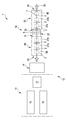
도 1은 차륜용 타이어를 제조하기 위한 설비를 개략 도시한 것이다.
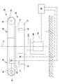
도 2는 도 1의 설비에 속하는 타이어를 제어하기 위한 기기의 입면도를 도시한 것이다.
도 3은 도 2의 기기의 평면도를 도시한 것이다.
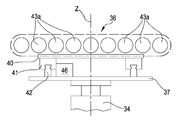
도 4는 앞선 도면의 기기의 한 부품의 사시도이다.
도 5는 도 4의 부품의 한 요소를 도시한 것이다.
도 6은 도 5의 요소의 변형이다.
도 7은 도 2의 기기의 일부의 확대도이다.
도 8a, 8b, 8c는 각각의 동작조건에서 도 7의 부분의 평면도를 도시한 것이다.
도 9는 도 1의 설비로 건조된 타이어의 반경방향 절반부를 도시한 것이다.This description will be given below with reference to the accompanying drawings, which are provided by way of non-limiting example only.
BRIEF DESCRIPTION OF THE DRAWINGS FIG. 1 schematically shows an apparatus for manufacturing a tire for a wheel.
Fig. 2 shows an elevational view of a device for controlling tires belonging to the equipment of Fig. 1;
Figure 3 shows a top view of the device of Figure 2;
4 is a perspective view of one part of the appliance of the preceding drawing.
Figure 5 shows an element of the part of figure 4;
Figure 6 is a variation of the element of Figure 5;
Fig. 7 is an enlarged view of a part of the device of Fig. 2;
Figures 8a, 8b, 8c show a top view of the portion of Figure 7 in each operating condition.
Figure 9 shows a radial half of the tire dried with the equipment of Figure 1;
도 1을 참조로, 참조번호(1)는 전체적으로 차륜용 타이어를 생산하기 위한 설비를 나타낸다. Referring to Fig. 1, reference numeral 1 denotes a facility for producing a tire for a wheel as a whole.
상기 설비에서 제조된 타이어(2)는 도 9에 도시되어 있고, 필연적으로 2개의 카카스 플라이(4a,4b)를 갖는 카카스 구조(3)를 포함한다. 불침투성 엘라스토머 재료층 또는 소위 라이너(5)가 카카스 플라이/플라이들(4a, 4b) 내부에 도포된다. 반경방향 외부위치에 엘라스토머 필러(6b)를 지닌 소위 비드코어(6a)를 각각 포함하는 2개의 고정환형구조(6)가 카커스 플라이/플라이들(4a, 4b)의 각각의 단부플랩과 결합된다. 고정환형구조(6)는 타이어(2)와 각각의 마운팅 림(mounting rim) 간에 치합이 정상적으로 발생하는 "비드(bead)"(7)라는 용어로 일반적으로 식별되는 영역에 근접하여 일체화된다. 벨트층(8a, 8b)을 포함하는 벨트구조(8)는 카커스 플라이/플라이(4a, 4b) 주위로 원주방향으로 부착되고 트레드 밴드(9)는 벨트구조(8)에 원주 상으로 중첩된다. 벨트구조(8)는 카커스 플라이/플라이들(4a, 4b)과 벨트구조(8)의 축방향 대향말단 에지 중 하나 사이에 각각 위치한 소위 "언더벨트 인서트"(10)와 결합될 수 있다. 해당 비드(7)로부터 트레드 밴드(9)의 대응하는 측방향 에지로 각각의 2개의 사이드월(11)이 카커스 플라이(4a, 4b)상의 측방향 대향위치에 부착된다. 각각의 사이드월(11)의 반경방향 외부와 트레드 밴드(9)의 축방향 외부 사이에 포함되는 부분은 타이어의 숄더로 알려져 있다.The
타이어(2)는, 타이어가 사용 중일 때, 각각의 비드(7)로부터 등거리이고 주 회전축 "X-X"에 수직인 중간라인 면("M")(도 9)을 갖는다. 중간라인 면("M")은 타이어(2)를 실질적으로 서로에 대해 미러링된(트레드 디자인를 제외하고는 전술한 중간라인 축("M")에 대해 대칭이 아닐 수도 있음) 제 1 축방향 절반부(2a)와 제 2 축방향 절반부(2b)로 분할한다.The
도 1에 도시된 설비(1)는 생타이어를 제조하기 위한 기기(13)에 의해 형성된 타이어(2) 생산라인(12)과, 건조(建造)기기(13)의 하류에 작동가능하게 배치된 적어도 하나의 몰딩 및 가황처리 유닛(14)을 포함한다.The plant 1 shown in Figure 1 comprises a
도 1에 도시된 설비(1)의 비제한적인 실시예에서, 건조장치(13)는 미도시된 성형드럼이 카커스 플라이(4a, 4b), 라이너(5), 고정환형구조물 및 가능하게는 사이드월(11)의 적어도 한 부분을 포함하는 카커스 슬리브를 각 성형드럼 상에 형성하도록 배열된 상이한 반제품 공급 작업대 사이에서 이동되는 카커스 건조라인(15)을 포함한다.In a non-limiting embodiment of the installation 1 shown in Fig. 1, the drying
동시에, 외부 슬리브 건조라인(16)에서, 하나 이상의 보조드럼(미도시)은 적어도 벨트구조(8), 트레드 밴드(9), 및 가능하게는 사이드월(11)의 적어도 한 부분을 각각의 보조드럼 상에 형성하도록 배열된 상이한 작업대 간에 순차적으로 이동된다.At the same time, in the outer
건조장치(13)는 외부 슬리브가 카커스 슬리브에 결합되는 조립 작업대(17)를 또한 포함한다.The drying
도시되지 않은 설비(1)의 다른 실시예에서, 건조장치(13)는 예를 들어 단일 드럼 상에 전술한 모든 구성요소를 형성하도록 배열된 상이한 유형일 수 있다.In another embodiment of the apparatus 1 not shown, the drying
건조된 타이어(2)는 최종적으로 몰딩 및 가황처리 유닛(14)으로 운송된다.The dried
생산라인(12)으로부터, 특히 몰딩 및 가황처리 유닛(14)으로부터, 완성된 타이어(2)는 미리 정의된 빈도 및 대응하는 소정의 생산 사이클 시간("Tcp")으로 순차적으로 차례로 빠져 나온다.From the
바람직하게는, 생산라인(12)의 하류 측에서, 설비(1)는 몰딩 및 가황처리 후에 상기 타이어(2)의 제어를 실행하도록 구성된 타이어를 제어하기 위한 기기(18)를 포함한다.Preferably, on the downstream side of the
설비(1)는, 조합하여 또는 대안으로, 건조의 마지막에 그리고 몰딩 및 가황처리 단계 전에 상기 타이어(2)의 제어를 실행하도록 구성된, 타이어를 제어하기 위한 동일한 기기(18)를 포함할 수 있다.The facility 1 may comprise the
도 1, 도 2 및 도 3의 실시예에서, 몰딩 및 가황처리 유닛(14)의 하류에 배치된 타이어를 제어하기 위한 이러한 기기(18)는 제품라인(12)과 각각의 배출구(21)에서 나오는 완성된 피제어 타이어(2)용의 유입구(20)를 갖는 제 1 제어유닛(19)을 포함한다. 제 1 제어유닛(19)의 하류에는, 상기 제 1 제어유닛(19)의 배출구(21)에 운송 및 전복장치(22)가 위치된다. 제 2 제어유닛(23)은 운송 및 전복장치(22) 및 각각의 배출구(25)에서 나온 완성된 타이어(2)용의 유입구(24)를 갖는 제 2 제어유닛(23)이 위치해 있다. 제 1 제어유닛(19)의 유입구(20)는 타이어를 제어하기 위한 기기(18)의 유입구를 구성한다. 제 2 제어유닛(23)의 배출구(25)는 타이어를 제어하기 위한 기기(18)의 배출구를 구성한다. 피제어 타이어(2)는 순서대로 차례로 입구(20)에 들어가고, 타이어를 제어하기 위한 기기(18)내의 제어경로(26)를 따라 순차적으로 이동되며, 배출구(25)를 향해 빠져 나온다. 제어경로(26)를 따라, 타이어(2)는 하기에 더 상세히 기술된 방식에 따라 발생가능한 결함의 유무를 확인하기 위해 품질 제어를 받는다.1, 2 and 3, such a
상술한 실시예에서, 제 1 제어유닛(19) 및 제 2 제어유닛(23)은 각각 제어경로(26)를 따라 서로 실질적으로 직진하는 공급방향("F")을 따라 순서대로 배치된 제 1 제어 작업대(27a) 및 제 2 제어 작업대(27b)를 포함한다.In the above-described embodiment, the
미도시된 다른 비제한적인 실시예에서, 제 1 제어유닛(19) 및 제 2 제어유닛(23)은 각각 제어경로(26)를 따라 그리고 실질적으로 직선의 공급방향("F")을 따라 순서대로 순차적으로 배치된 제 1 제어 작업대, 제 2 제어 작업대 및 제 3 제어 작업대를 포함한다.In a further non-limiting embodiment, not shown, the
미도시된 변형된 비제한적인 실시예에서, 제 1 제어유닛(19) 및 제 2 제어유닛(23)은 제어경로(26)의 2개의 직선 섹션을 정의하도록 서로에 대해 각을 이룬다.In a non-illustrated, modified, non-limiting embodiment, the
미도시된 다른 변형된 실시예에서, 제 1 제어유닛(19) 및 제 2 제어유닛(23)은 서로 겹쳐져 있다. 제 2 제어유닛(23)은 제 1 제어유닛(19) 위에 배치되고, 운송 및 전복장치(22)는 제 1 제어유닛(19) 및 제 2 제어유닛(23)의 말단에 위치된다. 상기 운송 및 전복장치(22)는 또한 제 1 제어유닛(19)으로부터 제 2 제어유닛(23)으로 타이어를 옮기도록 하는 식으로 타이어(2)를 리프팅하도록 구성된다.In another modified embodiment not shown, the
타이어를 제어하기 위한 기기(18)의 또 다른 실시예(미도시)는 전술한 제 1 및 제 2 제어유닛(19, 23)의 기능을 수행하는 단일 제어유닛 및 운송 및 전복장치(22)를 포함한다. 상기 단일 제어유닛은 순차적으로 배치되고 상세하게 상술한 바와 같은 2개의 제어 작업대(27a, 27b)를 포함한다. 타이어를 제어하기 위한 기기(18)는 또한, 예를 들어, 상기 단일 제어 작업대의 배출구와 유입구 사이에 작동가능하게 개재된 추가의 컨베이어 벨트를 포함한다. 보조운송장치는 단일 제어 작업대로부터 나오는 타이어(2)를 다시 한번 유입구로 운송하도록 구성된다.Another embodiment (not shown) of the
각각의 상기 제어 작업대(27a, 27b)는 지면에 대해 접촉하도록 구성된 하부(29) 및 상기 하부(29) 위에 연장된 상부(30)를 갖는 프레임(28)을 포함한다(도 4는 제 1 제어 작업대(27a)를 도시한 것이다). 도시된 프레임(28)은 평면도로 정사각형 또는 직사각형의 꼭지점에 배치된 4개의 수직 업라이트(31)에 의해 형성된 프레임 워크이다. 수직 업라이트(31)는 상부 부분(30)에서(제어경로(26)와 평행하게 배향된) 상부 길이방향 크로스피스(32a) 쌍에 의해 그리고(제어경로(26)에 직각으로 배향된) 복수의 상부 횡방향 크로스피스(32b)에 의해 상부에서 연결된다.Each of the
하부(29)에서 복수의 하부 길이방향 크로스피스(33a) 및 복수의 하부 횡방향 크로스피스(33b)에 의해 연결된 동일한 수직의 수직 업라이트(31)가 하부에 있다.The lower vertical 29 is the same vertical
프레임 워크 내에서, (도 5 및 도 6에 도시된 바와 같이) 지면에 접하거나 하부 크로스피스(33a, 33b)에 의해 지지되는 베이스(34)가 수용된다. 베이스(34)에는 회전 테이블(35)이 수직 회전축("Z") 주위로 회전할 수 있도록 실장되어 있다. 회전 테이블(35)은 완성된 피제어 타이어(2)의 사이드월(11)을 수용하고 지지하도록 구성된 실질적으로 수평인 접촉부(36)를 갖는다.Within the framework, a
도시된 실시예에 따르면, 회전 테이블(35)은 베이스(34) 위에 배치되고 수직 회전축("Z") 주위에서 베이스(34)에 회전 가능하게 결합되는 회전 지지체(37)를 포함한다. 회전 지지체(37)는 베이스(34)로부터 나온 샤프트(37A)와 일체이다. 샤프트(37A)는 베이스(34)에 설치된 이동장치(38)(도 5에 개략적으로 도시됨)에 연결되고, 상기 수직 회전축("Z") 주위로 회전 테이블(35)을 회전하도록 구성된다. 수직 회전축("Z")은 베이스(34)에 대해 그리고 지면에 대해 고정되어 있다.According to the illustrated embodiment, the rotary table 35 includes a
무단 컨베이어(39)는 회전 지지체(37) 상에 실장된다. 특히, 무단 컨베이어(39)는 그 하부면에 배치된 한 쌍의 슬라이딩 블록(41)이 제공된 플레이트에 의해 형성된 슬라이드(40)를 포함한다. 각 슬라이딩 블록(41)은 회전 지지대(37)의 상면에 실장된 가이드(42)와 슬라이딩 가능하게 결합된다.The
슬라이드(40)는, 상부면에, 브래킷(미도시)에 피벗 지지되고 슬라이드(40)와 일체로 형성된 한 쌍의 롤러(43)를 지닌다. 롤러(43)는 서로 평행하고 가이드(42)에 평행한 각각의 회전축(W) 주위로 회전 이동될 수 있다. 컨베이어 벨트(44)는 폐쇄경로를 정의하도록 상기 한 쌍의 롤러(43) 상에 권선되며 상부면이 실질적으로 수평면에 놓이는 상기 접촉부(36)를 형성하는 상부 브랜치를 갖는다.The
도 5에 개략적으로 도시된 제 1 액추에이터(45)는 슬라이드 상에 실장되며, 롤러를 회전시키고 컨베이어 벨트(44)가 폐쇄 경로를 따라 이동하도록 한 쌍의 2개 롤러(43) 중 적어도 하나에 동작가능하게 연결된다. 롤러(43)는 제 1 방향("x")으로, 일방향으로 또는 반대방향으로 상부 브랜치 및 접촉부(36)의 평행이동을 발생하도록 일회전방향으로 또는 반대방향으로 회전하게 제조될 수 있다. A
도 5에 개략적으로 도시된 제 2 액츄에이터(46)는 슬라이드와 회전 지지체(37) 사이에 실실장되고, 제 1 방향("x")에 수직인 제 2 방향("y")을 따라 가이드(42)상에서 슬라이드(40)를 이동시키도록 구성된다. 따라서, 접촉부(36)는 상기 접촉부(36)에 대해 대신 고정된 수직 회전축("Z")에 대해 상기 2방향("x, y")을 따라 수평면으로 이동될 수 있다. 제 1 방향("x")을 따른 상기 접촉부(36)의 이동은 연속적이며 무한할 수 있다. 제 2 방향을 따른 접촉부(36)의 이동은 슬라이딩 블록(41) 및 가이드(42)로 구성된 시스템에 의해 제공되는 이용가능한 이동에 의해 제한된다.A
컨베이어 벨트(44) 대신에 도시되지 않은 다른 실시예에서, 무단 컨베이어(39)는 서로 평행하고 회전 지지체(37) 상에 실장된 복수의 전동롤러(43a)를 포함한다. 이 경우, 상기 전동롤러(43a)의 상부면은 상기 접합부(36)를 형성한다.In another embodiment, not shown, instead of the
회전 테이블(35) 위에(도 2 및 도 4에 개략적으로 도시된) 광학 타입의 감지장치(47)가 설치되고, 접촉부(36)를 향해 대면한다. 감지장치(47)는 예를 들어 하나 이상의 카메라 및 제어 작업대(27a, 27b) 내부에 배치된 복수의 카메라들이 제공된다. 도시된 실시예에서, 감지장치(47)는 상부 횡방향 크로스피스(32b) 중 하나에 실장된다.An optical type sensing device 47 (shown schematically in FIGS. 2 and 4) is mounted on the rotary table 35 and confronts the
전자관리유닛(48)(도 4 및 도 5)은 감지장치(47), 이동장치(38), 제 1 액츄에이터(45) 및 제 2 액추에이터(46)에 작동가능하게 연결된다. 전자관리유닛(48)은 회전 테이블(35)의 수직 회전축("Z")과 접촉부(36)에 놓인 타이어(2)의 주축("X-X") 간에 변위("S")를 감지하고, 제 1 및 제 2 액츄에이터(45,46)를 구동하며, 예를 들어, 약 0.1mm 이하와 같이 사전설정된 값보다 작은 변위를 하도록, 감지된 변위("S")의 함수로서 제 1 방향("x") 및/또는 제 2 방향("y")에 따라 접촉부(36)를 이동시키도록 구성된다. The electronic management unit 48 (Figures 4 and 5) is operatively connected to the
각각의 상기 제어 작업대(27a, 27b)는 회전 테이블(35) 위에 실장되고 상부 크로스피스(32b)(도 4)에 구속된 2개의 유인형 로봇암(49)을 포함한다. 상기 각각의 유인형 로봇암(49)은 횡방향 상부 크로스피스(32b)에 결합된 베이스부 및 상기 베이스부로부터 시작하여 연속적으로 배치되고 조인트에 의해 연결된 일련의 요소를 갖는다. 유인형 로봇암(49)은 예를 들어 6 또는 7 축/자유도를 갖는다. 각각의 유인형 로봇암(49)은 접촉부(36) 위의 상부 횡방향 크로스피스(32b)로부터 돌출하여 연장된다.Each of the
각각의 유인형 로봇암(49)의 종단부는 하나 이상의 장치 또는 제어도구(50)를 지닌다. 접촉부(36)과 전술한 상부 횡방향 크로스피스(32b) 사이에서, 프레임(28)은 유인형 로봇암(49) 및 제어도구(50)에 대한 기동 공간을 한정한다. 유인형 로봇암(49)은 제어도구(50)에 대한 지지 및 이동장치를 정의한다. 유인형 로봇암(49)이 지닌 도구들은 가령 (반경방향 외부 및/또는 반경방향 내부면에) 있을 수 있는 외부 결함 및/또는 (구조내) 타이어의 내부 결함을 감지하게 하는 일련의 비파괴 제어작업을 수행 할 수 있다. 상기 제어는 예를 들어 광학 타입(사진, 관측, 홀로그램, 방사선 촬영 등), 초음파 타입, 기계적 타입 또는 이들의 조합일 수 있다. 도구(50)는 회전 테이블(35) 위에 작동가능하게 동작한다.The end of each attracted
비배타적인 예로서, 상기 도구는 가령 타이어의 표면의 2차원 및/또는 3차원 이미지를 촬영하도록 구성된 레이저 타입의 분산광, 그레이징광 또는 직사광을 갖는 가능한 광원을 갖는 디지털 카메라를 포함할 수 있다.As a non-exclusive example, the tool may include a digital camera having a laser source of dispersive light, gray light or a possible light source having direct light, e.g. configured to capture two-dimensional and / or three-dimensional images of the surface of a tire.
운송 및 전복장치(22)는 지면에 접하도록 구성된 각각의 프레임(53)을 포함한다(도 1, 도 2 및 도 3). 프레임(53)은 수평 전복 축("K")을 정의하는 전복핀 둘레에 힌지 결합된 한 쌍의 평행하고 이격된 측벽(54)을 갖는다. 벽(54) 사이에는, 2개의 일련의 전달롤러(55)가 연장되어 벽(54)에 회전가능하게 결합된다. 각각의 일련의 전달롤러는 타이어(2)에 대한 이동가능한 운송면을 갖는 지지부를 형성하는 방식으로 동일한 평면 상에 놓이는 복수의 평행한 수평 전달롤러(55)를 포함한다. 2개의 일련의 상술한 전달롤러(55)는 상호 이격되어 있고 사이에 전복될 타이어(2)를 수용하기 위한 시트가 정해진다. 시트는 후술하는 바와 같이 타이어(2)의 이동을 허용하기 위해 대향 개구를 갖는다. 공간의 하나 또는 두 개의 개구는 스톱요소, 예를 들어 폐쇄 위치와 개방 위치 간에 움직일 수 있는 일종의 게이트에 의해 선택적으로 폐쇄된다. 측벽(54) 그자체와 전달롤러(55)에 의해 형성된 조립체를 전복 축("K") 주위로 회전시키기 위해, 도시되지 않은 모터가 측벽(54)에 작동가능하게 연결된다. 측벽(54) 및 전달롤러(55)에 의해 형성된 상기 조립체는 하나의 일련의 전달롤러(55)가 지면 아래에 평행하게 배치된 제 1 위치 및 다른 일련의 전달롤러(55)가 하부에 배치되는 제 2 위치 사이에 전복 축("K") 주위로 움직일 수 있다. 시트 내에 있을 때, 타이어(2)는 아래에 위치된 일련의 전달롤러(55)상의 사이드월벽(11)에 대해 접한다. 도시되지 않은 또 다른 모터는 이들을 회전시키고 이로 인해 접촉한 타이어(2)를 이동시키기 위해 전달롤러(55) 중 적어도 일부에 작동가능하게 연결된다. 스톱요소는 전복동안 타이어(2)가 운송 및 전복장치(22) 밖으로 떨어지는 것을 방지하는 역할을 한다. 도 1, 도 2 및 도 3의 실시예에서, 운송 및 전복장치(22)는 제 1 제어유닛(19)에 속하는 제 2 제어 작업대(27b)와 제 2 제어유닛(23)에 속하는 제 1 제어 작업대(27a) 사이에 위치된다. 전복 축("K")은 제어경로(26)에 수직이고, 제 1 또는 제 2 위치에서, 아래에 배치된 시리즈의 전달롤러(55)는 제 1 제어유닛(19)에 속하는 제 2 제어 작업대(27b) 및 제 2 제어유닛(23)에 속하는 제 1 제어 작업대(27a)의 접촉부(36)와 실질적으로 동일한 높이에 위치해 있다.The transport and overturn
제 1 제어유닛(19)의 제 1 작업대(27a)의 상류에는, 타이어(2)가 제 1 작업대(27a)에 공급되기 전에 타이어(2)가 위치된 롤러유닛을 포함하는 기계식 센터링 지지부(56)가 위치된다. 특히, 기계식 센터링 지지부(56)는 지면에 접하는 프레임(57)과, 상기 프레임(57) 상에 회전가능하게 실장된 복수의 롤러(58)를 포함한다. 기계식 센터링 지지부(56)는 또한 제어경로(26)에 대해 대향측에 배치된 한 쌍의 측면(59)을 포함한다. 측면(59)은 서로 가까이 또는 멀리 또는 기계식 센터링 지지부(56)의 중간라인 축("P")으로/으로부터 대칭으로 이동하도록 기계적으로 구속된다. 타이어(2)는 롤러유닛에 대해 접하고 타이어의 대향하는 부분들에 대해 접촉함으로써, 후술되는 바와 같이, 측방향으로 사전센터링하는 상기 측면들(59) 사이에 배치된다.Upstream of the first work table 27a of the
제 2 제어유닛(23)의 제 2 작업대의 하류에는, 배출 롤러유닛(60)이 배치된다.Downstream of the second work table of the
기계식 센터링 지지부(56)와 제 1 제어유닛(19)의 제 1 작업대(27a) 사이에, 제 1 제어유닛(19)과 제 2 제어유닛(23)의 연이은 제어 작업대(27a,27b) 사이에, 운송 및 전복장치(22)와 제 1 제어유닛(19)의 제 1 작업대(27a)와 이에 인접한 제 2 제어유닛(23)의 제어 작업대(27a) 사이에, 그리고 제 2 제어유닛(23)의 제어 작업대(27b)와 배출롤러 유닛(60) 사이에, 각각의 전달그룹(61)은 하나의 제어 작업대(27a)로부터 후속 작업대(27b)로(또는 하나의 제어 작업대(27b)으로부터 운송 및 전복장치(22)로 또는 운송 및 전복장치로부터 제어 작업대(27a)로 또는 제어 작업대(27b)로부터 롤러유닛(60)으로) 통과 중에 타이어(2)의 사이드월(11)의 적어도 일부분을 지지하고 이에 따라 낙하를 방지하도록 구성된다.Between the mechanical centering
각각의 전달그룹(61)은 기계식 센터링 지지체(56)의 롤러(58)의 회전축에 평행한 각각의 회전축을 갖는 동력전달롤러(62)를 구비한다(도 7 및 도 8a, 도 8b 및도 8c). 각각의 전달그룹(61)은 동력전달롤러(62)의 하류 및 상류에 각각 배치되고 상기 동력전달롤러(62)에 평행한 2개의 보조전달롤러(63)를 또한 포함할 수 있다. 동력전달롤러(62)는 상기 롤러를 회전시키도록 구성된 개략적으로 도시된 각각의 모터(64)에 연결되어 있다. 2개의 보조전달롤러(63)는 바람직하게는 휴지상태이다. 2개의 보조전달롤러(63)는 또한 작업위치와 휴지위치 사이의 수직 방향을 따라 제 3 액추에이터(65)에 의해 이동될 수 있다. 작업위치(도 7에서 실선으로 도시됨)에서, 2개의 보조전달롤러(63)는 상승된 위치에 놓이고 실질적으로 동력전달롤러(62) 및 접촉부(36)의 높이에 위치된다. (도 7에서 대시선으로 도시된) 휴지위치에서, 2개의 보조전달롤러(63)는 하강된 위치에 놓이고, 동력전달롤러(62)와 접촉부(36) 아래에 배치된다. 상승된 위치에서, 이들은 이동 타이어(2)용의 지지부를 제공한다. 하강된 위치에서, 이들은 회전 테이블이 수직 회전축("Z") 주위로 방해받지 않고 회전할 수 있도록 인접한 회전 테이블(35) 주위에 충분한 공간을 남긴다.Each
상술한 전자관리유닛(48)은 제 1 제어유닛(19) 및 제 2 제어유닛(23)의 유인형 로봇암(49), 제어도구(50), 이동장치(38), 제 1 액츄에이터(45), 제 2 액츄에이터(46), 모터(64), 제 3 액츄에이터(65), 및 운송 및 전복장치(22)의 미도시된 모터에 동작가능하게 연결된다. 상기 전자관리유닛은 전체 설비(1)의 동일한 전자관리유닛일 수 있거나 설비(1)의 다른 부분에 전용인 하나 이상의 다른 유닛들에 동작가능하게 연결될 수 있다. 전자관리유닛은 상류에 배치된 생산 라인(12)과 협력하여 타이어를 제어하기 위한 기기(18)의 작동을 관리한다.The
사용 중에 그리고 본 발명에 따른 타이어를 제어하는 방법(및 도 1, 2 및 3을 참조)에 따르면, 완성된 타이어(2)가 가황처리 유닛(14)을 빠져 나올 때마다, 예를 들어, 컨베이어(미도시)를 통해 기계식 센터링 지지부(56)로 운송된다. 여기서 측면(59)은 타이어(2)와 상호작용해 측면으로 사전센터링되므로, 상기 타이어(2)의 주 회전축("X-X")은 적어도 중간라인 축("P") 부근에(제 2 방향("y")을 따라 사전 센터링한)측면 변위("Sy")가 20-25mm 미만으로 놓이게 된다. According to the method of controlling the tire according to the invention (and also FIGS. 1, 2 and 3) during use and every time the
그 후, 타이어(2)는 제 1 제어유닛(19)의 제 1 제어 작업대(27a)로 공급되는 반면, 2개의 보조전달롤러(63)는 상승된 위치에 놓이고 타이어(2)는 그 위에서 접촉해 슬라이딩한다(도 7 및 8a). 림에 실장되지 않은(따라서 수축된) 타이어(2)는 각각의 컨베이어 벨트(36)의 상부 브랜치에 대해 사이드월(11)과 접한다. 제 1 방향("x")이 공급방향("F")과 일치하도록 접촉부(36)가 지향된다. 사이드월(11)에 맞닿은 타이어(2)는 접촉부(36)에 인접한 축방향의 제 2 절반부(2b)와 위로 지향된 축방향의 제 1 절반부(2a)를 갖는다.The
사이드월(11)에 대한 접촉부는 타이어(2)를 팽창시키지 않고도 모든 테스트 동안 타이어(2)의 형태가 항상 동일한 것을 보장한다. 휴지(수축)상태에서 타이어(2)는 팽창된 타이어에 대해 동일한 진동을 감소시키고 제어 품질, 특히 획득된 이미지를 향상시킨다. 사이드월에 대한 접촉부는 무결성 및 제어 품질을 손상시킬 수 있는 상당한 기계적 스트레스를 방지한다. 사이드월에 대한 접촉부는 또한 이하에서 설명되는 바와 같이 제어의 기준 시스템에 대한 용이한 센터링을 허용한다.The contact with the
전자관리유닛(48)은 기기(18) 및 진입 타이어(2)의 크기를 알고, 적절한 계산에 의해, 타이어(2)의 주 회전축("X-X")이(제 1 방향("x")을 따라 사전센터링하며) 길이방향 변위("Sx")가 20-25mm 미만으로 다소 회전 테이블(35)의 회전축("Z")에 있는 것 같을 때, 제 1 액츄에이터(45)를 구동한다. 컨베이어 벨트(44)는 일시적으로 정지된다(도 8b). 예를 들어, Sx = 15mm, Sy = 20mm이면, S = 25mm이다.The
이때, 기기(18)는 타이어(2)의 실제 미세한 센터링을 제공한다. 타이어(2)가 완벽하게 원형이 아니기 때문에, 각각의 타이어(2)의 주 회전축은 본 명세서에 기술되지 않은 적절한 알고리즘에 의해 먼저 계산된다. 예를 들어, 감지장치(47)는 타이어의 다수 지점의 위치를 감지하고 전자관리유닛(48)은 가상의 주 회전축("X-X")을 계산한다.At this time, the
그런 후, 감지장치(47)는 회전 테이블(35)의 수직 회전축("Z")과 타이어(2)의 주 회전축("X-X") 사이에 존재하는 변위("S")를 감지하고, 전자관리유닛(48)에 상기 변위("S")를 나타내는 신호를 전송한다. 사전센터링으로 인해, 이러한 변위("S")는 일반적으로 약 25mm 미만이다.Then, the
전자관리유닛(48)은 제 1 액츄에이터(45) 및/또는 제 2 액추에이터(46)를 구동하고, 상기 변위("S")가 사전설정된 값 이하, 예를 들면 약 0.1mm 이하로 감소 될 때까지 접촉부(36)를 이동시키고, 실질적으로 상기 변위를 상쇄시킨다(도 8c). 전자관리유닛(48)은 접촉부(36)가 이동함에 따라 상기 변위("S")를 나타내는 신호를 계속 수신하고, 소정의 센터링을 얻을 때까지 제 1 액추에이터(45) 및/또는 제 2 액추에이터(46)를 계속 구동한다. 센터링 루틴은 가령 약 2 초의 지속시간("Tcent")을 갖는다. 전자관리유닛(48)에 의해 관리되는 최대 정밀 센터링 이동은 약 25mm보다 작다. 변위("S")의 상술한 값이 달성되지 않으면, 동일한 사이클에 따라 절차가 반복된다. 이러한 방식으로, 25mm보다 큰 초기 변위("S")가 있더라도, 원하는 허용오차 값에 따라 타이어(2)를 센터링할 수 있다.The
마지막으로, 일단 센터링되면, 타이어(2)는 수직 회전축("Z")과 실질적으로 일치하는 회전축("X-X")을 갖는다; 그러한 상황에서, 유인형 로봇암(49)은 항상 동일한 타이어(2)의 크기의 함수로서 할당된 위치에 위치될 수 있다.Finally, once centered, the
연이어, 각각의 제어도구(50)가 타이어(2)에 도달할 때까지 유인형 로봇암(49)이 기동 공간으로 이동된다.Subsequently, until the
회전 테이블(35)의 상류 및 하류에 배치된 전달그룹(61)의 2개의 보조전달롤러(63)는 하강 위치로 이동되고, 제어도구(50)를 고정된 위치에 유지하면서, 회전 테이블(35) 및 타이어(2)는 수직 회전축("Z")(도 4 및 도 8c) 주위로 회전된다. 이러한 회전동안, 도구(50)는 타이어(2)의 축방향 제 1 절반부(2a)에 한 제어 사이클을 실행하도록 제공한다. 이러한 제어는 연속 사이클 및 각 사이클에서 실행되고, 동일한 제어 작업대(27a, 27b)의 제어도구(50)가 동일한 타이어(2)의 상이한 부분을 제어하기 위해 상이한 위치에 배치된다.The two
일단 제어 사이클이 종료되면, 회전 테이블(35)의 회전은 공급방향("F")과 정렬된 제 1 방향("x")으로 정지되고 유인형 로봇암(49)은 타이어(2)로부터 멀어지게 이동된다. 회전 테이블(35)의 상류 측 및 하류 측에 배치된 전달그룹(61)의 2개의 보조전달롤러(63)는 상승 위치로 이동된다. 타이어(2)가 놓이는 제 1 제어 작업대(27a)의 컨베이어 벨트(44)는 동일한 사이드월(11)에 항상 접한 타이어(2)가 제어경로(26)를 따라 피치를 완성시키고 타이어(2)를 상기 제 2 제어 작업대(27b)의 접촉부(36) 상으로 이동될 때까지 제 2 제어 작업대(27b)의 컨베이어 벨트(44)와 함께 그리고 동력전달롤러(62)와 함께 이동된다. 타이어(2)는 제 1 제어 작업대(27a)으로부터 하적되고 제 2 제어 작업대(27b)에 적재된다.Once the control cycle is completed, the rotation of the rotary table 35 is stopped in a first direction ("x") aligned with the feed direction ("F") and the driven
적재 동안, 제 1 제어 작업대(27a)를 참조로 이미 상술한 바와 같이, 제 1 방향("x")을 따라 사전센터링이 실행되고, 적재 후에(전술한 동일한 모드에 따라) 실제 미세 센터링이 제 2 제어 작업대(27b)의 회전축("Z")에 대해 실행된다.Pre-centering is performed along the first direction ("x"), as described above with reference to the
타이어(2)는 축방향 제 1 절반부(2a)가 항상 위로 지향된 제 2 제어 작업대(27b)에 남아 있고 다른 제어 싸이클은 제 1 제어 작업대(27a)에 대해 설명된 바와 유사한 방식으로 항상 실행된다. The
제 1 제어유닛(19)에 그리고 상기 제 1 유닛(19)에 의해 정의된 제어경로(26)의 제 1 부분을 따라, 타이어(2)의 축방향 제 1 절반부(2a)는 복수의 제어를 받는다. 이러한 제어부는 바람직하게는 축방향 제 1 절반부(2a)의 전체 표면(내부 및 외부)을 덮는다.Along the first portion of the
이러한 제어는 광학적 타입(예를 들어, 사진, 관측학, 홀로그래피, 방사선 사진 등), 초음파 타입, 기계적 타입 또는 이들의 조합일 수 있다.Such control may be of an optical type (e.g., photograph, observation, holography, radiography, etc.), ultrasonic type, mechanical type or a combination thereof.
이때, 타이어(2)의 회전은 정지되고, 타이어(2)가 놓인 제 2 제어 작업대(27b)의 컨베이어 벨트(44)는 하류에 배치된 동력전달롤러(62)와 함께 그리고 항상 동일한 사이드월(11)에 접촉한 타이어(2)가 제어경로(26)를 따라 피치를 완성시키고 타이어(2)를 운송 및 전복의 중심으로 실질적으로 옮겨갈 때까지(상승된 위치에 배치된) 운송 및 전복장치(22)의 전달롤러(55)와 함께 이동된다. At this time, the rotation of the
측벽(54), 전달롤러(55) 및 타이어(2)에 의해 형성된 조립체는 전복 축("K")주위로 180°전복된다. 이러한 전복 축("K")은 상기 주 회전축("Z")에 수직인 상기 타이어(2)의 축 방향 중간라인 면에 속한다. 상부에 위치된 타이어(2)의 축방향 절반부(2a)는 이제 전달롤러(55)에 대해 맞닿은 각각의 사이드월(11)과 함께 아래에 놓인다. 아래쪽에 위치된 타이어(2)의 축방향 제 2 절반부(2b)는 이제 위로 향한다.The assembly formed by the
연이어, 제 2 제어유닛(23)에 속하는 제 1 제어 작업대(27a)의 전달롤러(55) 및 컨베이어 벨트(44)를 구동함으로써, 타이어(2)는 제 2 제어유닛(23)으로 운송되고, 제 2 절반부(2b)는 축방향 절반부(2a)에 대해 상술한 바와 같은 모드(사전센터링, 미세 센터링, 제어, 하적)로, 제어경로(26)의 제 2 부분을 따라, 축방향 제 1 절반부(2a)의 것에 대한 타입과 개수에 대해 유사한, 바람직하게는 동일한 제어를 받는다. The
제 2 제어유닛(23)의 배출구에서, 타이어(2)가 배출롤러유닛(60)에 공급될 때, 타이어(2)의 축방향 절반부(2a, 2b)는 정확히 제어된다.At the outlet of the
작동 조건에서, 제 1 및 제 2 제어유닛(19, 23) 모두의 각각의 제어 작업대(27a, 27b) 및 운송 및 전복장치(22)는 가황처리 유닛(14)으로부터 연속적으로 배출되는 타이어(2)를 수용한다. 상기 타이어(2)는 하나의 제어 작업대으로부터 다른 제어 작업대(27a, 27b)로의 제어경로(26)를 따라 단계적으로 또는 운송 및 전복장치(22)로 동시에 전진된다("워킹 빔" 이동이라고 함). 후속단계 사이에서, 상기 타이어(2)는 운송 및 전복장치(22) 내의 각각의 제어 작업대(27a, 27b)에 동일 시간동안 체류한다.Each of the
이는 하나의 타이어(2)가 각각의 제어 사이클 시간("Tcc")마다 타이어를 제어하기 위한 기기(18)로 진입하고 상기 하나의 타이어(2)가 상기 기기(18)로부터 빠져 나가는 것을 의미한다. 상기 제어 사이클 시간("Tcc")은 실질적으로 생산 사이클 시간("Tcp")과 같아질 수 있으므로, 생산라인(12)은 타이어를 제어하기 위한 기기(18)와 동기화될 수 있다. 따라서, 생산라인(12)을 빠져 나가는 각각의 타이어(2)는 중간 보상영역(버퍼)을 필요없이 타이어를 제어하기 위한 장치(18)에 직접 진입 할 수 있다.This means that one
Claims (26)
베이스(34);
각각의 수직축(Z) 주위로 회전할 수 있도록 상기 베이스(34)에 실장된 회전 테이블(35);
상기 회전 테이블(35)에서 작동가능하게 동작하는 적어도 하나의 제어장치(50);
상기 수직 회전축(Z) 주위로 상기 회전 테이블(35)을 회전시키는 이동장치(38);
두 방향(x, y)을 따라 접촉부(36)를 이동시키기 위해 상기 접촉부(36)에 작동가능하게 연결된 적어도 하나의 액츄에이터(45, 46);
수직 회전축(Z)과 타이어(2)의 주축(X-X) 사이에 실질적인 상기 수평면상에 변위(S)를 감지하도록 구성된 감지장치(47); 및
상기 감지장치(47)와 상기 적어도 하나의 액추에이터(45, 46)에 작동가능하게 연결된 전자관리유닛(48)을 포함하고,
회전 테이블(35)은 상기 수직 회전축(Z)에 대해 실질적으로 수평 및 수직 면에 놓이고 피제어 타이어(2)의 사이드월(11)을 수용하고 지지하도록 구성된 접촉부(36)를 포함하며; 상기 접촉부(36)는 실질적으로 상기 수평 면에 속하는 두 방향(x, y)을 따라 수직 회전축(Z)에 대해 실질적으로 수평인 상기 면에서 이동 가능하고,
전자관리유닛(48)은 액츄에이터(45,46)를 구동시키고, 이러한 변위가 사전설정된 값보다 작아지게 하도록 감지된 변위(S)의 함수로서 상기 두 방향(x, y) 중 적어도 하나를 따라 상기 접촉부(36)를 이동시키도록 구성되는 타이어를 제어하기 위한 기기.An apparatus for controlling a tire, each wheel having a main axis of rotation (XX), said apparatus comprising at least one control platform (27a, 27b), said at least one control platform (27a, 27b)
A base 34;
A rotary table 35 mounted on the base 34 for rotation about respective vertical axes Z;
At least one control device (50) operatively operable in said rotary table (35);
A moving device (38) for rotating the rotary table (35) around the vertical rotation axis (Z);
At least one actuator (45, 46) operatively connected to the contact (36) for moving the contact (36) along two directions (x, y);
A sensing device 47 configured to sense the displacement S on substantially the horizontal plane between the vertical rotation axis Z and the main axis XX of the tire 2; And
An electronic management unit (48) operatively connected to the sensing device (47) and the at least one actuator (45, 46)
The rotary table 35 includes a contact portion 36 which is placed on a substantially horizontal and vertical plane with respect to the vertical rotation axis Z and is configured to receive and support the sidewall 11 of the controlled tire 2; The contact portion 36 is movable in the plane substantially perpendicular to the vertical axis of rotation Z along two directions (x, y) substantially belonging to the horizontal plane,
The electronic management unit 48 drives the actuators 45 and 46 and controls the actuators 45 and 46 to move along at least one of the two directions x and y as a function of the sensed displacement S to make the displacement less than a predetermined value. An apparatus for controlling a tire configured to move a contact (36).
전자관리유닛(48)은 실질적으로 상기 변위(S)를 소거해 회전축(Z)에 대해 타이어(2)를 센터링하도록 구성된 타이어를 제어하기 위한 기기.The method according to claim 1,
The electronic control unit (48) is configured to substantially eliminate said displacement (S) to center the tire (2) about the rotational axis (Z).
감지장치(47)는 광학적 타입인 타이어를 제어하기 위한 기기.3. The method according to claim 1 or 2,
The sensing device 47 is an apparatus for controlling a tire of an optical type.
회전 테이블(35)은 상기 두 방향(x, y) 중 제 1 방향(x)을 따라 이동될 수 있고 상기 접촉부(36)를 지니는 무단 컨베이터(39)를 포함하고, 상기 무단 컨베이터(39)도 또한 상기 두 방향(x, y) 중 제 2 방향(y)을 따라 기정의된 이동동안 이동될 수 있는 타이어를 제어하기 위한 기기.4. The method according to any one of claims 1 to 3,
The rotary table 35 includes an endless conveyor 39 which can be moved along the first direction x of the two directions x and y and which has the contact portion 36 and the endless conveyor 39 ) Is also moveable during the predetermined movement along the second direction (y) of the two directions (x, y).
무단 컨베이어(39)는 한 쌍의 롤러(43)에 권선된 컨베이어 벨트(44)를 포함하고, 상기 컨베이어 벨트(44)의 상부면이 접촉부(36)를 정의하는 타이어를 제어하기 위한 기기.5. The method of claim 4,
Wherein the endless conveyor 39 comprises a conveyor belt 44 wound on a pair of rollers 43 and the upper surface of the conveyor belt 44 defines a contact 36. [
무단 컨베이어(39)는 복수의 동력롤러(43a)를 포함하고, 상기 동력롤러(43a)의 상부면의 조립체가 상기 접촉부(36)를 정의하는 타이어를 제어하기 위한 기기.5. The method of claim 4,
Wherein the endless conveyor (39) includes a plurality of power rollers (43a), and an assembly of upper surfaces of the power rollers (43a) defines the contact portions (36).
회전 테이블(35)은 상기 수직 회전축(Z) 주위로 베이스(34)에 회전 가능하게 결합된 회전 지지체(37)를 포함하고, 무단 컨베이어(39)는 회전 지지체(37)에 실장되며, 제 2 방향(y)을 따라 상기 회전 지지체(37)에 대해 이동될 수 있는 타이어를 제어하기 위한 기기.7. The method according to any one of claims 4 to 6,
The rotary table 35 includes a rotary support 37 rotatably coupled to the base 34 about the vertical axis of rotation Z. The endless conveyor 39 is mounted on the rotary support 37, A device for controlling a tire which can be moved relative to said rotary support (37) along a direction (y).
복수의 제어 작업대(27a,27b)를 포함하는 타이어를 제어하기 위한 기기.8. The method according to any one of claims 1 to 7,
An apparatus for controlling a tire comprising a plurality of control benches (27a, 27b).
각 제어 작업대(27a, 27b)와 다음 제어 작업대(27a, 27b) 사이에는 적어도 하나의 전달롤러(62)를 포함하는 전달그룹(61)이 배치되는 타이어를 제어하기 위한 기기.9. The method of claim 8,
And a transfer group (61) including at least one transfer roller (62) is disposed between each control workbench (27a, 27b) and the next control workbench (27a, 27b).
상기 적어도 하나의 전달롤러(62)는 동력전달되는 타이어를 제어하기 위한 기기.10. The method according to any one of claims 1 to 9,
The at least one transfer roller (62) is adapted to control the power transmitted to the tire.
전달그룹(61)은 전달롤러(62)의 하류 및 상류에 각각 배치된 2 이상의 보조전달롤러(63)를 포함하는 타이어를 제어하기 위한 기기.11. The method according to claim 9 or 10,
Wherein the transfer group (61) comprises two or more auxiliary transfer rollers (63) respectively disposed downstream and upstream of the transfer roller (62).
전달그룹(61)은 움직이는 타이어(2)를 지지하기 위해 하나의 제어유닛(27a, 27b)와 다음 제어유닛(27a, 27b) 사이에 놓이는 작업위치 및 회전 테이블(들)(35)의 자유 회전을 허용하는 휴지위치 사이에서 이동될 수 있는 타이어를 제어하기 위한 기기.12. The method according to any one of claims 9 to 11,
The transfer group 61 includes a working position lying between one control unit 27a and 27b and the next control unit 27a and 27b and a free rotation of the rotary table (s) 35 to support the moving tire 2, And a rest position for permitting the restraining of the tire.
보조전달롤러(63)는 움직이는 타이어(2)를 지지하기 위해 하나의 제어유닛(27a, 27b)과 다음 제어유닛(27a, 27b) 사이에 있는 작업위치와 회전 테이블(들)(35)의 자유 회전을 허용하는 휴지위치 사이에서 이동될 수 있는 타이어를 제어하기 위한 기기.12. The method of claim 11,
The auxiliary transfer roller 63 is movable between a working position between one control unit 27a and 27b and the next control unit 27a and 27b to support the moving tire 2 and the free position of the rotary table (s) And a rest position for permitting rotation of the tire.
휴지위치에서, 전달그룹(61) 또는 보조전달롤러(63)는 회전 테이블(35)에 대해 하부 위치에 배치되는 타이어를 제어하기 위한 기기.The method according to claim 12 or 13,
In the rest position, the transfer group (61) or the auxiliary transfer roller (63) is arranged at a lower position relative to the rotary table (35).
상기 방법은:
i. 실질적으로 수평면에 직각인 회전축(Z)을 갖는 각각의 회전 테이블(35)에 속하는 접촉부(36) 상에 피제어 타이어(2)를 공급하는 단계,
ii. 상기 접촉부(36)에 공급된 타이어(2)의 주 회전축(X-X)과 상기 회전축(Z) 간에 있는 실질적인 상기 수평면 상에 변위(S)를 감지하는 단계;
iii. 기설정된 값 미만으로 상기 변위(S)가 감소될 때까지 적어도 하나의 방향(x,y)을 따라 수직 회전축(Z)에 대해 실질적인 상기 수평면에서 상기 회전 테이블(35)의 접촉부(36)를 이동시키는 단계;
iv. 상기 회전 테이블(35)의 수직 회전축(Z) 주위로 타이어(2)와 함께 회전 테이블(35)을 회전시키는 단계; 및
v. 회전 테이블(35)과 타이어(2)가 회전하는 동안 상기 타이어(2)에 대한 제어를 실행하는 단계를 포함하는 타이어를 제어하기 위한 방법.CLAIMS 1. A method for controlling a tire, each tire having a main rotation axis (XX)
The method comprising:
i. Feeding a controlled tire (2) onto a contact portion (36) belonging to each rotary table (35) having a rotation axis (Z) perpendicular to the horizontal plane,
ii. Sensing a displacement (S) on substantially the horizontal plane between the main rotation axis (XX) of the tire (2) supplied to the contact portion (36) and the rotation axis (Z);
iii. (36) of the rotary table (35) in the substantially horizontal plane with respect to the vertical rotation axis (Z) along at least one direction (x, y) until the displacement (S) ;
iv. Rotating the rotary table (35) together with the tire (2) around the vertical rotation axis (Z) of the rotary table (35); And
v. And performing control on the tire (2) while the rotary table (35) and the tire (2) are rotating.
상기 제어를 실행하는 단계의 마지막에,
vi. 상기 회전 테이블(35)의 상기 접촉부(36)로부터 상기 타이어(2)를 하적하는 단계가 제공되는 타이어를 제어하기 위한 방법.16. The method of claim 15,
At the end of the step of executing the control,
vi. Wherein the step of lowering the tire (2) from the contact portion (36) of the rotary table (35) is provided.
상기 기설정된 값은 약 1mm 미만인 타이어를 제어하기 위한 방법.17. The method according to claim 15 or 16,
Wherein the predetermined value is less than about 1 mm.
상기 회전 테이블(35)의 접촉부(36)를 이동시키는 단계는:
실질적으로 상기 수평면 상의 두 방향(x,y)을 따라 상기 접촉부(36)를 이동시키는 단계를 포함하는 타이어를 제어하기 위한 방법.18. The method according to any one of claims 15 to 17,
The step of moving the contact portion (36) of the rotary table (35) comprises:
And moving said contact (36) substantially along two directions (x, y) on said horizontal plane.
상기 회전 테이블(35)의 접촉부(36)를 이동시키는 단계는:
상기 두 방향(x,y) 중 제 1 방향(x)을 따라 상기 접촉부(36)를 지닌 무단 캐리어(39)를 이동시키는 단계를 포함하는 타이어를 제어하기 위한 방법.19. The method of claim 18,
The step of moving the contact portion (36) of the rotary table (35) comprises:
Moving the endless carrier (39) with the contact (36) along a first one of the two directions (x, y).
상기 회전 테이블(35)의 상기 접촉부(36)를 이동시키는 단계는:
상기 두 방향(x,y) 중 제 2 방향(y)을 따라 기정의된 이동동안 무단 캐리어(39)를 이동시키는 단계를 포함하는 타이어를 제어하기 위한 방법.20. The method according to claim 18 or 19,
The step of moving the contact portion (36) of the rotary table (35) comprises:
Moving the endless carrier (39) during a predetermined movement along a second direction (y) of the two directions (x, y).
상기 두 방향(x,y)은 서로에 대해 직각인 타이어를 제어하기 위한 방법.21. The method according to any one of claims 18 to 20,
Wherein the two directions (x, y) are perpendicular to each other.
타이어(2)를 공급하는 단계는:
전체 타이어(2)가 회전테이블(35) 상에 놓일 때까지 상기 두 방향(x,y) 중 제 1 방향(x)을 따라 상기 회전 테이블(35)의 접촉부(36)를 이동시킴으로써 회전 테이블(35)에 상기 타이어(2)를 적재하는 단계를 포함하는 타이어를 제어하기 위한 방법.19. The method of claim 18,
The step of supplying the tire (2) comprises:
By moving the contact portion 36 of the rotary table 35 along a first one of the two directions x and y until the entire tire 2 is placed on the rotary table 35, 35) of the tire (2).
적재 동안 타이어(2)의 통과를 감지하고 기정의된 이동 후 제 1 방향(x)을 따른 접촉부(36)의 이동을 중지시킴으로써 제 1 방향(x)을 따라 타이어(2)를 사전센터링하는 단계를 포함하는 타이어를 제어하기 위한 방법.23. The method of claim 22,
Precuring the tire 2 along the first direction x by sensing the passage of the tire 2 during loading and stopping the movement of the contact portion 36 along the first direction x after the predetermined movement ≪ / RTI >
제어경로(26)를 따라 복수의 타이어(2)를 단계별로 동시에 전진시키는 단계와, 연이은 단계들 간에 놓인 시간간격 동안 상기 타이어(2)에 대한 제어를 실행하는 단계를 포함하고; 각 간격에, ii에서 v까지의 단계를 실행하도록 제공되는 타이어를 제어하기 위한 방법.24. The method according to any one of claims 15 to 23,
Advancing a plurality of tires (2) step by step along a control path (26), and performing control on the tire (2) during a time interval between successive steps; A method for controlling a tire provided to perform steps from ii to v in each interval.
전진시키는 단계는:
하나의 회전 테이블(3)과 다음 회전 테이블(35) 간에 또는 하나의 회전 테이블(35)과 운송그룹(61)에 의한 운송 및 전복장치(22) 간에 각 타이어(2)를 지지하는 단계를 포함하는 타이어를 제어하기 위한 방법.25. The method of claim 24,
Advancing steps include:
Supporting each tire 2 between one rotary table 3 and a next rotary table 35 or between a rotary table 35 and a transport and overturn device 22 by a transport group 61 / RTI >
상기 회전 테이블(35)의 자유 회전을 허용하기 위해 회전 테이블(35)을 회전시키기 전에 운송그룹(61)을 하강시키는 단계를 포함하는 타이어를 제어하기 위한 방법.26. The method of claim 25,
And lowering the transport group (61) before rotating the rotary table (35) to allow free rotation of the rotary table (35).
Applications Claiming Priority (3)
| Application Number | Priority Date | Filing Date | Title |
|---|---|---|---|
| ITMI20150616 | 2015-04-30 | ||
| ITMI2015A000616 | 2015-04-30 | ||
| PCT/IB2016/052201 WO2016174543A1 (en) | 2015-04-30 | 2016-04-18 | Process and apparatus for controlling tyres, in a process and plant for manufacturing tyres for vehicle wheels |
Publications (2)
| Publication Number | Publication Date |
|---|---|
| KR20170142172A true KR20170142172A (en) | 2017-12-27 |
| KR102582977B1 KR102582977B1 (en) | 2023-09-26 |
Family
ID=53765300
Family Applications (1)
| Application Number | Title | Priority Date | Filing Date |
|---|---|---|---|
| KR1020177031033A KR102582977B1 (en) | 2015-04-30 | 2016-04-18 | Method and device for controlling tires in processes and facilities for manufacturing tires for vehicles |
Country Status (9)
| Country | Link |
|---|---|
| US (1) | US10458883B2 (en) |
| EP (1) | EP3289330B1 (en) |
| JP (1) | JP6715859B2 (en) |
| KR (1) | KR102582977B1 (en) |
| CN (1) | CN107532971B (en) |
| BR (1) | BR112017022664B8 (en) |
| MX (1) | MX371335B (en) |
| RU (1) | RU2705443C2 (en) |
| WO (1) | WO2016174543A1 (en) |
Families Citing this family (10)
| Publication number | Priority date | Publication date | Assignee | Title |
|---|---|---|---|---|
| ITUB20156028A1 (en) * | 2015-11-30 | 2017-05-30 | Pirelli | Method and apparatus for controlling tires for vehicle wheels |
| JP7074670B2 (en) | 2015-12-16 | 2022-05-24 | ピレリ・タイヤ・ソチエタ・ペル・アツィオーニ | Devices and methods for analyzing tires |
| US10605698B2 (en) | 2015-12-16 | 2020-03-31 | Pirelli Tyre S.P.A. | Method and apparatus for checking tyres |
| MX2018008102A (en) | 2015-12-28 | 2018-12-17 | Pirelli | Apparatus and method for checking tyres. |
| EP3397938B1 (en) * | 2015-12-28 | 2019-08-28 | Pirelli Tyre S.p.A. | Apparatus for checking tyres |
| EP3491359B1 (en) | 2016-07-26 | 2023-09-06 | Pirelli Tyre S.p.A. | Method and station for checking tyres for vehicle wheels |
| JP6865278B2 (en) * | 2017-06-06 | 2021-04-28 | 三菱重工機械システム株式会社 | Tire transport device, tire test system equipped with this, and tire transport method |
| CN111492221B (en) * | 2017-12-20 | 2022-11-08 | 倍耐力轮胎股份公司 | Method and apparatus for inspecting tyres in a process and plant for building tyres for vehicle wheels |
| US20210146643A1 (en) * | 2018-04-18 | 2021-05-20 | Pirelli Tyre S.P.A. | Method for building green tyres |
| WO2021188019A1 (en) * | 2020-03-18 | 2021-09-23 | Общество С Ограниченной Ответственностью "Моcагротех" | Method for inspecting vehicle tyres |
Citations (3)
| Publication number | Priority date | Publication date | Assignee | Title |
|---|---|---|---|---|
| JP2008203258A (en) * | 2007-02-16 | 2008-09-04 | Bernward Maehner | Tire test device and its method |
| DE102008037356A1 (en) * | 2008-08-12 | 2010-03-04 | Mähner, Bernward | Testing arrangement for testing tire, has conveyor system with sensors detecting presence of tire in conveyor section of conveyor system, and control device registering position of tire and tracing movement of tire |
| DE102013102296A1 (en) * | 2012-12-21 | 2014-06-26 | Bernward Mähner | Device and method for testing a tire by means of an interferometric, in particular shearographic, measuring method |
Family Cites Families (8)
| Publication number | Priority date | Publication date | Assignee | Title |
|---|---|---|---|---|
| US3969627A (en) | 1974-08-07 | 1976-07-13 | Picker Corporation | System of positioning and inspecting tires |
| CN100465607C (en) | 2001-12-04 | 2009-03-04 | 株式会社普利司通 | Method and device for inspecting tire |
| US8284393B2 (en) * | 2008-06-04 | 2012-10-09 | Kobe Steel, Ltd. | Tire shape inspection method and tire shape inspection device |
| CN101710027B (en) * | 2009-11-24 | 2011-06-01 | 江苏大学 | Non-linear dynamic characteristic monitoring system and method of vehicle tyre |
| JP5518571B2 (en) * | 2010-05-24 | 2014-06-11 | 株式会社ブリヂストン | Tire appearance inspection apparatus and appearance inspection method |
| US8824878B2 (en) | 2010-11-25 | 2014-09-02 | Toyo Tire & Rubber Co., Ltd. | Illumination device and inspection device of tire |
| US9110032B2 (en) * | 2013-03-14 | 2015-08-18 | Integro Technologies Corp. | System and methods for inspecting tire wheel assemblies |
| CN106164642B (en) * | 2014-04-11 | 2019-04-19 | 三菱重工机械系统株式会社 | Tire holding meanss, tire test system |
-
2016
- 2016-04-18 CN CN201680022979.XA patent/CN107532971B/en active Active
- 2016-04-18 KR KR1020177031033A patent/KR102582977B1/en active IP Right Grant
- 2016-04-18 US US15/568,709 patent/US10458883B2/en active Active
- 2016-04-18 JP JP2017548929A patent/JP6715859B2/en active Active
- 2016-04-18 RU RU2017135286A patent/RU2705443C2/en active
- 2016-04-18 MX MX2017013015A patent/MX371335B/en active IP Right Grant
- 2016-04-18 EP EP16726165.0A patent/EP3289330B1/en active Active
- 2016-04-18 WO PCT/IB2016/052201 patent/WO2016174543A1/en active Application Filing
- 2016-04-18 BR BR112017022664A patent/BR112017022664B8/en active IP Right Grant
Patent Citations (3)
| Publication number | Priority date | Publication date | Assignee | Title |
|---|---|---|---|---|
| JP2008203258A (en) * | 2007-02-16 | 2008-09-04 | Bernward Maehner | Tire test device and its method |
| DE102008037356A1 (en) * | 2008-08-12 | 2010-03-04 | Mähner, Bernward | Testing arrangement for testing tire, has conveyor system with sensors detecting presence of tire in conveyor section of conveyor system, and control device registering position of tire and tracing movement of tire |
| DE102013102296A1 (en) * | 2012-12-21 | 2014-06-26 | Bernward Mähner | Device and method for testing a tire by means of an interferometric, in particular shearographic, measuring method |
Also Published As
| Publication number | Publication date |
|---|---|
| CN107532971A (en) | 2018-01-02 |
| US10458883B2 (en) | 2019-10-29 |
| JP2018521299A (en) | 2018-08-02 |
| CN107532971B (en) | 2020-04-10 |
| JP6715859B2 (en) | 2020-07-01 |
| BR112017022664A2 (en) | 2018-07-17 |
| KR102582977B1 (en) | 2023-09-26 |
| RU2017135286A3 (en) | 2019-09-12 |
| RU2017135286A (en) | 2019-04-05 |
| US20180143102A1 (en) | 2018-05-24 |
| MX371335B (en) | 2020-01-23 |
| RU2705443C2 (en) | 2019-11-07 |
| BR112017022664B1 (en) | 2022-07-05 |
| EP3289330B1 (en) | 2020-01-01 |
| EP3289330A1 (en) | 2018-03-07 |
| WO2016174543A1 (en) | 2016-11-03 |
| BR112017022664B8 (en) | 2022-08-09 |
| MX2017013015A (en) | 2017-12-08 |
Similar Documents
| Publication | Publication Date | Title |
|---|---|---|
| KR20170142172A (en) | Method and apparatus for controlling tire in process and apparatus for manufacturing wheel tire | |
| US10627314B2 (en) | Apparatus for checking tyres having first and second check units | |
| US10775273B2 (en) | Method and line for checking tyres for vehicle wheels | |
| US9429498B2 (en) | Tire testing machine | |
| JP6005276B2 (en) | Tire conveyance method, tire conveyance fixing device, and tire inspection system | |
| US10213975B2 (en) | Automatic system and method for mounting and dismounting tire casing on expandable rim hub in retreading operations | |
| ITUA20163534A1 (en) | Method and control line of tires for vehicle wheels | |
| US11428607B2 (en) | Station for checking tyres configured for overturning tyres perpendicular to a tyre rotation axis | |
| JP5955476B1 (en) | Tire inspection system | |
| US10926500B2 (en) | Method and device for handling tires | |
| CN109789654B (en) | Method and apparatus for handling green tyres | |
| WO2023188566A1 (en) | Tire manufacturing method and manufacturing system |
Legal Events
| Date | Code | Title | Description |
|---|---|---|---|
| E902 | Notification of reason for refusal | ||
| E902 | Notification of reason for refusal | ||
| E701 | Decision to grant or registration of patent right | ||
| GRNT | Written decision to grant |