KR20170140248A - Constant load brush - Google Patents
Constant load brush Download PDFInfo
- Publication number
- KR20170140248A KR20170140248A KR1020177031579A KR20177031579A KR20170140248A KR 20170140248 A KR20170140248 A KR 20170140248A KR 1020177031579 A KR1020177031579 A KR 1020177031579A KR 20177031579 A KR20177031579 A KR 20177031579A KR 20170140248 A KR20170140248 A KR 20170140248A
- Authority
- KR
- South Korea
- Prior art keywords
- pressing portion
- feedback element
- load
- feedback
- brush head
- Prior art date
Links
Images


Classifications
-
- A—HUMAN NECESSITIES
- A46—BRUSHWARE
- A46B—BRUSHES
- A46B5/00—Brush bodies; Handles integral with brushware
- A46B5/002—Brush bodies; Handles integral with brushware having articulations, joints or flexible portions
- A46B5/0054—Brush bodies; Handles integral with brushware having articulations, joints or flexible portions designed to allow relative positioning of the head to body
- A46B5/0062—Brush bodies; Handles integral with brushware having articulations, joints or flexible portions designed to allow relative positioning of the head to body being flexible or resilient during use
- A46B5/0066—Flexible resilience by elastic deformation of the material
-
- A—HUMAN NECESSITIES
- A46—BRUSHWARE
- A46B—BRUSHES
- A46B15/00—Other brushes; Brushes with additional arrangements
- A46B15/0002—Arrangements for enhancing monitoring or controlling the brushing process
- A46B15/0038—Arrangements for enhancing monitoring or controlling the brushing process with signalling means
- A46B15/004—Arrangements for enhancing monitoring or controlling the brushing process with signalling means with an acoustic signalling means, e.g. noise
-
- A—HUMAN NECESSITIES
- A46—BRUSHWARE
- A46B—BRUSHES
- A46B5/00—Brush bodies; Handles integral with brushware
- A46B5/002—Brush bodies; Handles integral with brushware having articulations, joints or flexible portions
- A46B5/0033—Brush bodies; Handles integral with brushware having articulations, joints or flexible portions bending or stretching or collapsing
- A46B5/0041—Mechanical joint or hinge, made up of several components
-
- A—HUMAN NECESSITIES
- A46—BRUSHWARE
- A46B—BRUSHES
- A46B5/00—Brush bodies; Handles integral with brushware
- A46B5/002—Brush bodies; Handles integral with brushware having articulations, joints or flexible portions
- A46B5/0054—Brush bodies; Handles integral with brushware having articulations, joints or flexible portions designed to allow relative positioning of the head to body
- A46B5/0058—Mechanical joint or hinge made up of several components
-
- A—HUMAN NECESSITIES
- A46—BRUSHWARE
- A46B—BRUSHES
- A46B5/00—Brush bodies; Handles integral with brushware
- A46B5/002—Brush bodies; Handles integral with brushware having articulations, joints or flexible portions
- A46B5/0054—Brush bodies; Handles integral with brushware having articulations, joints or flexible portions designed to allow relative positioning of the head to body
- A46B5/0075—Brush bodies; Handles integral with brushware having articulations, joints or flexible portions designed to allow relative positioning of the head to body being adjustable and stable during use
- A46B5/0083—Mechanical joint allowing adjustment in at least one plane
-
- A—HUMAN NECESSITIES
- A46—BRUSHWARE
- A46B—BRUSHES
- A46B5/00—Brush bodies; Handles integral with brushware
- A46B5/06—Brush bodies; Handles integral with brushware in the form of tapes, chains, flexible shafts, springs, mats or the like
-
- A—HUMAN NECESSITIES
- A46—BRUSHWARE
- A46B—BRUSHES
- A46B9/00—Arrangements of the bristles in the brush body
- A46B9/02—Position or arrangement of bristles in relation to surface of the brush body, e.g. inclined, in rows, in groups
- A46B9/04—Arranged like in or for toothbrushes
-
- A—HUMAN NECESSITIES
- A46—BRUSHWARE
- A46B—BRUSHES
- A46B2200/00—Brushes characterized by their functions, uses or applications
- A46B2200/10—For human or animal care
- A46B2200/1066—Toothbrush for cleaning the teeth or dentures
Abstract
The constant load brushes 100, 200 and 300 include the handles 130, 230 and 330, the brush heads 110, 210 and 310, and the response pieces 120, 120 ', 220 and 320. The brush heads 110, 210, 310 are pivotally disposed on the handles 130, 230, 330 and are movable within respective ranges. The response pieces 120, 120 ', 220 and 320 are provided between the brush heads 110, 210 and 310 and the handles 130, 230 and 330 and are resilient and have a normal protruded state, And has a collapsed recessed state. The brush heads 110, 210 and 310 press the responder pieces 120, 120 ', 220 and 320 as they move to allow the responder pieces 120, 120', 220 and 320 to enter the collapsed, And provides a feedback response. The constant load brushes (100, 200, 300) solve the problem of excessive constant load errors or constant load failures that occur when the brushes withstand an external load exceeding a threshold value.
Description
The present invention relates to brushes, and more particularly to stress control brushes.
Good brushing habits help maintain oral hygiene and prevent tooth decay. To maintain oral hygiene, people brush their teeth daily with a strong load to prevent tooth corrosion. However, according to the report, the researchers pointed out that when teeth are wiped too hard, the surfaces of teeth and gums are damaged, increasing the risk of tooth decay and periodontal disease.
WO WO021035 discloses a toothbrush capable of automatically releasing excessive tooth brushing force. The brush head of the brush is pivoted by the handles and the two opposing ends of the flat resilient plate connect the brush head and the handle respectively so that the angle between the brush head and the handle is a fixed value. When the brushing force exceeds a predetermined force value, the elastic plate is bent and deformed to significantly change the angle between the brush head and the handle. When the load is applied continuously on a toothbrush having a flat elastic plate, the angle between the brush head and the handle is more significantly changed so that the toothbrush can not maintain normal toothbrush function; Damage to the teeth and gums caused by excessive brushing load can be avoided.
U. S. Patent No. 6,327, 734 discloses a sensing and signaling system for a toothbrush that informs the user that the load applied to the tooth exceeds a threshold. The toothbrush includes a brush-head member and a collapsible and recoverable dome member. The brush-head member includes a striking element that contacts the surface of the dome member and extends away from the back of the brush-head member. When the brush-head member applies a load on the user's teeth, the brush-head member is moved toward the toothbrush and transfers the load to the dome member by the striking element. When an excessive load is applied by the user to the brush-head against the tooth, the dome member is folded and the brush-head is moved toward the toothbrush to inform the user. When the excessive load is removed, the dome member is restored to its original shape and pushes the brush-head member to its original position.
Taiwan Utility Model M492666 discloses a stress control brush and the stress control brush uses feedback from the elastic plate to inform the user that the brush load exceeds a predetermined load value. In the stress control brush, the elastic plate connects the brush head and the handle. When the brushing load exceeds a predetermined load value, the elastic plate is brought into a collapsed bending state, and the angle between the brush head and the handle is significantly changed so that the stress control brush can maintain normal toothbrush function, Damage to the teeth and gums caused by the brushing load can be prevented. The brush head has a limiting part, and the handle has a limiting part. When the elastic plate is folded and bent, the brush head and the limiting portions of the handle can be adjacent to each other to limit the bending curvature of the elastic plate.
The above described toothbrush can inform the user whether the load applied to the tooth during brushing damages the teeth and gums, but there is a problem when the user uses the toothbrush described above. WO WO 01/21035 discloses that when the load exceeds a predetermined value, the angle between the brush head and the handle changes significantly and becomes temporarily unavailable, causing plastic deformation to become unusable, Furthermore, there is the problem that the actual force that causes the deformation of the toothbrush when the user brushes and the actual trigger force that causes deformation of the toothbrush are different each time. If the user wishes to wipe particularly dirty parts of the tooth, such as residues between teeth, such a toothbrush can not meet the user's desire for a brush with a stronger load.
U.S. Patent No. 6,327,734 has a complicated structure and load transfer mechanism and assembly. When the toothbrush is in use, the complicated structure and tiny interspaces can cause deformation and the triggering force of the brushes can be different each time and residues and contaminants are easily retained inside the brush head, which is difficult to dry and hard to dry. When the environment in the brush head is too humid and the residue and contaminants are retained, the bacteria grow considerably and these brushes become easily dirty and increase the likelihood of infection.
The stress control brush disclosed in Taiwan Utility Model No. M492666 has an elastic plate having a slightly bent state and a folded and bent state when the stress control brush is used. The difference between the modulus of elasticity of the elastic plate in the slightly bent state and the modulus of elasticity of the elastic plate in the folded and bent state is small so that some users can not feel the load feedback generated by the elastic plate when using the stress control brush.
SUMMARY OF THE INVENTION The present invention provides a stress control brush for solving problems caused by loads greater than a critical load, which is tolerated by a conventional toothbrush. For example, the problems are deviation of actual load from a predetermined critical load that is too large, and out of function.
In order to achieve the above-mentioned object, an embodiment of the present invention provides a stress control brush comprising a handle, a brush head and a feedback element. The brush head is pivoted on the handle, and the brush head is pivotable with respect to the handle in each range. A feedback element is provided between the handle and the brush head. The feedback element is resilient and has a protruding state and a breakdown-sunken state. The feedback element is pressed in a breakdown-sunken state by the brush head when the brush head is pivoted relative to the handle, and feedback is provided by the feedback element.
The technical effects of the present invention are as follows:
Once the user applies a load that damages the teeth and gums when brushing the teeth with the brush of the present invention, the load causes the feedback element to break down-to-sunken and greatly deforms so that the brush is significantly deformed and provides feedback to the user, The user is instructed to stop brushing with a load that damages the teeth and gums.
The following provides a detailed description of the invention with respect to the figures and specific embodiments, but does not limit the invention.
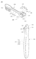
1 is a schematic view of a stress control brush according to a first embodiment of the present invention.
2 is an exploded view of a stress control brush according to a first embodiment of the present invention.
Figure 3a is a schematic diagram of a first type feedback element according to a first embodiment of the present invention.
Figure 3B is a side view of a first type feedback element according to the first embodiment of the present invention.
3c is a schematic view of a load-displacement curve of a first type feedback element according to a first embodiment of the present invention.
4A and 4B are cross-sectional views of a stress control brush according to a first embodiment of the present invention.
5A is a schematic diagram of a second type of feedback element according to the first embodiment of the present invention.
Figure 5B is a side view of a second type of feedback element according to the first embodiment of the present invention.
Figure 5c is a schematic view of the load-displacement curve of a feedback element of a second type according to the first embodiment of the present invention.
6 is a schematic view of a stress control brush according to a second embodiment of the present invention.
7 is an exploded view of a stress control brush according to a second embodiment of the present invention.
8 is a cross-sectional view of a stress control brush according to a second embodiment of the present invention.
9 is a cross-sectional view of a stress control brush according to a third embodiment of the present invention.
10A to 10C are schematic views of a stress control brush according to fourth to sixth embodiments of the present invention.
The following provides a detailed description of the structure and operating principle of the present invention with reference to the drawings.
1 to 3C. 1 is a schematic view of a stress control brush according to a first embodiment of the present invention. 2 is an exploded view of a stress control brush according to a first embodiment of the present invention. Figure 3a is a schematic diagram of a first type feedback element according to a first embodiment of the present invention. Figure 3B is a side view of a first type feedback element according to the first embodiment of the present invention. 3c is a schematic view of a load-displacement curve of a first type feedback element according to a first embodiment of the present invention.
The
The
In the first embodiment of the present invention, the extending direction of the
In the first embodiment of the present invention, the bristle
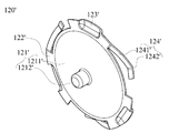
3A-3C, the
The first protruding
The
The second
When the
The
See FIGS. 4A and 4B. 4A and 4B are cross-sectional views of a stress control brush according to a first embodiment of the present invention. As shown in FIG. 4A, when the
When the first load Fl is equal to or less than the critical load, the load applied to the
When the first load F1 is greater than the critical load, the load applied on the
When the user uses a tongue-wringing portion (not shown) of the
Once the angle between the extension of the
In addition, when the
In addition, the critical elastic load of the
In a first embodiment of the invention, the
The modulus of elasticity of the first projecting portion 1211 'is determined by the modulus of elasticity of the respective support portion 124' and the total modulus of elasticity of all the support portions 124 'by the influence of the structure of the first projecting portion 1211' Lt; / RTI > As a result, the load acting on each support portion 124 'to generate an elastic deformation is less than the load acting on the first projecting portion 1211' to generate an elastic deformation. When the
The distance between the first
On the other hand, in the second type of feedback element 120 ', the support portion 124' is formed in the support portion (not shown) so as to fill the tolerance of the distance between the first
Further, in a first embodiment of the present invention, the
Please refer to Figs. 6 to 8. 6 is a schematic view of a stress control brush according to a second embodiment of the present invention. 7 is an exploded view of a stress control brush according to a second embodiment of the present invention. 8 is a cross-sectional view of a stress control brush according to a second embodiment of the present invention. The stress control brush according to the second embodiment of the present invention is similar to the stress control brush according to the first embodiment of the present invention, except that the stress control brush according to the second embodiment and the stress control brush according to the first embodiment The differences are described herein, and the same structure is not repeated here.
The
The
The
In the second embodiment of the present invention two
See FIG. 9 is a cross-sectional view of a stress control brush according to a third embodiment of the present invention. The stress control brush according to the third embodiment of the present invention is similar to the stress control brush according to the first embodiment of the present invention, but the difference between the stress control brush according to the third embodiment and the stress control brush according to the first embodiment Is that the position of the pressing portion and the limiting portion of the brush head and the position of the pressing portion and the limiting portion of the handle are exchanged, respectively, and the same structure is not repeated here.
The stress control brush according to the third embodiment of the present invention includes a
The first
The
10A to 10C and Table 1. 10A to 10C are schematic views of a stress control brush according to fourth to sixth embodiments of the present invention. Table 1 shows experimental data on the number of bristle bundles of the stress control brush, the length of the brush head, the critical elastic load of the feedback element, and other variables in some embodiments of the present invention. In Table 1, the experimental data is the calculation result for bending the feedback element with a fixed size, assuming that the two teeth are in contact with 24 bristle bundles, and the total pressure acting on the tooth Is 150 g. The stress control brushes according to the fourth to sixth embodiments are similar to the stress control brush according to the first embodiment, except that the stress control brush according to the fourth to sixth embodiments and the stress according to the first embodiment The differences of the control brushes are described here, and the same structure is not repeated here.
In the
In the
(Bundle)
According to the stress control brush of the present invention, when the user uses an appropriate load to brush the teeth, the disc structure of the feedback element makes the feedback element similar to the rigid body, and the deformation of the feedback element is rather small. Once the user uses a load that can cause damage to the teeth and gums for brushing, the projections are resiliently sunk-deformation causing the feedback element to collapse and considerable deformation such as bending of the stress control brush also occurs. A significant modification of the stress control brush provides feedback to the user to inform and stop the user brushing with a brushing load that can damage the teeth and gums. For example, the user may hear a noise or sudden bending deformation when the user uses the stress control brush, informing the user that the current brushing load may damage the teeth and gums.
Further, in the stress control brush of the present invention, the feedback element has a protruding structure, so that the elastic modulus of the feedback element can be significantly larger than the elastic modulus of the conventional bending feedback element. As a result, when the user brushes with a brush load less than the critical load, the deformation of the stress control brush of the present invention is much smaller than the deformation of the brush with a curved feedback element. Once the user brushes with a bristle load that is greater than the critical load, the feeling of sudden bending deformation as feedback generated by the stress control brush of the present invention is a frustrated feel caused by a brush with curved feedback elements , The feedback effect of the stress control brush of the present invention can be significantly improved.
Further, when the brush head of the stress control brush of the present invention withstands a brush load greater than the first threshold load, the brush head is pivoted relative to the handle such that the first limit portion and the second limit portion are pressed against each other, Deformation of the protrusion of the feedback element causing the irreversible plastic deformation and the pivoting of the brush head against the handle.
Also, when the stress control brush of the present invention is used, the mechanism by which the load is directly transmitted to the protrusion of the feedback element in contact with the brush head through the brush head is a transmittance by passing through many movable elements, Load losses can be avoided, and the value of the load that causes deformation each time can be made constant to improve the stress control effect.
In addition, in the stress control brush of the present invention, when the first limit portion and the second limit portion are pressed against each other, the user can easily grasp the teeth of the teeth, such as residues between teeth, without the situation where the stress control brush is excessively deformed and becomes unusable. Especially, it is possible to apply a larger load to the brush head in order to wipe the dirty part.
Further, in the present invention, the first limit portion is located outside the brush hand, the second limit portion is located outside the handle, and the pivot structure is located outside the oral cavity during brushing; Therefore, it is desirable that the residues and contaminants in the oral cavity are difficult to get into the pivot structure, that there is a small space in which the contaminants can stay, the brush is easy to clean, is kept dry and the residue and contaminants increase the likelihood of infection Related hygiene problems and to prevent the propagation of bacteria within a humid environment.
100: Stress control brush
110: Brush head
111: bristle sheet
112: bristle bundle
113: first limit portion
114: first pressing portion
115: first pivot portion
116: accommodation space
120: Feedback factor
121:
122; Side portion
123: Standing section
130: Handle
131: Grip
132: second limit portion
133: third limit portion
134: second pressing portion
135: second pivot portion
140: Pivoting element
Claims (13)
A brush head pivoted on said handle and pivotable about said handle in an angular range; And
A feedback element disposed between the handle and the brush head;
/ RTI >
The feedback element is resilient and has a protruding state and a breakdown-sunken state,
Wherein the feedback element is pressed in the breakdown-sunken state by the brush head when the brush head is pivoted relative to the handle, and feedback is provided by the feedback element.
Wherein the brush head further comprises a bristle seat and at least one first limit portion, the at least one first limit portion being connected to the bristle sheet, Grip and at least one second limit portion, wherein the at least one second limit portion is connected to the grip, and when the feedback element is in the break-down-sunken condition, the at least one first limit And the at least one second limit portion are adjacent to each other to limit the angular extent of the brush head.
Wherein the brush head further comprises a first pressing portion connected to the bristle sheet, wherein the first pressing portion and the at least one first limiting portion protrude out from one side of the bristle sheet, Wherein the at least one first limiting portion together defines a containment space, the handle further comprising a second pressing portion projecting outwardly from the handle and positioned within the containment space.
Wherein the second pressing portion is located between the first pressing portion and the at least one limiting portion and the feedback element is clamped between the first pressing portion and the second pressing portion, Wherein the first pressing portion and the second pressing portion press the feedback element when pivoted relative to the handle.
Wherein the number of the at least one first limiting portion is two, the two first limiting portions are located at one side of the first pressing portion, and the second pressing portion is positioned between the two first limiting portions Wherein the elastic element is clamped between the first pressing portion and the second pressing portion.
The second pressing portion is a recess, and the feedback element is located within the recess.
Wherein the first pressing portion is a recess and the feedback element is positioned within the recess.
Wherein the brush head further comprises a plurality of bristle bundles, wherein the bristle sheets have a front and a back facing each other, a plurality of bristle bundles are positioned on the front face, Wherein the feedback element is in the break-down-sunken state when a first load greater than a critical load is applied.
Wherein the handle further comprises a third limiting portion connected to the grip and wherein when a second load is applied to the brush head along a direction toward the back surface, the first pressing portion and the third pressing portion contact the brush head The stress control brush being adjacent to one another to limit the respective extent of the stress.
Wherein the feedback element further comprises a protrusion, the protrusion comprising a first protruding portion and a second protruding portion, the second protruding portion protruding out of the first protruding portion.
Wherein the feedback element further comprises at least one support portion connected to the protrusion and the protrusion, wherein the at least one support portion extends away from the protrusion and the extending direction of the at least one support portion is in the direction of protrusion of the protrusion Opposite stress control brush.
Wherein the feedback element comprises a disk shape.
Wherein the feedback is a combination of load feedback, acoustic feedback, strain feedback, or load feedback, acoustic feedback, and strain feedback.
Applications Claiming Priority (3)
| Application Number | Priority Date | Filing Date | Title |
|---|---|---|---|
| CN201510153033.4A CN106136566B (en) | 2015-04-02 | Determine power brushing tool | |
| CN201510153033.4 | 2015-04-02 | ||
| PCT/CN2016/076669 WO2016155512A1 (en) | 2015-04-02 | 2016-03-18 | Constant force brush |
Publications (1)
| Publication Number | Publication Date |
|---|---|
| KR20170140248A true KR20170140248A (en) | 2017-12-20 |
Family
ID=57003921
Family Applications (1)
| Application Number | Title | Priority Date | Filing Date |
|---|---|---|---|
| KR1020177031579A KR20170140248A (en) | 2015-04-02 | 2016-03-18 | Constant load brush |
Country Status (4)
| Country | Link |
|---|---|
| US (1) | US10321753B2 (en) |
| JP (1) | JP6529522B2 (en) |
| KR (1) | KR20170140248A (en) |
| WO (1) | WO2016155512A1 (en) |
Families Citing this family (2)
| Publication number | Priority date | Publication date | Assignee | Title |
|---|---|---|---|---|
| KR20170140248A (en) | 2015-04-02 | 2017-12-20 | 테-쿵 리 | Constant load brush |
| US11627799B2 (en) * | 2020-12-04 | 2023-04-18 | Keith McRobert | Slidable work surface |
Family Cites Families (17)
| Publication number | Priority date | Publication date | Assignee | Title |
|---|---|---|---|---|
| JPS59174036U (en) * | 1983-05-07 | 1984-11-20 | 宮川 元一 | toothbrush |
| JP3005953U (en) * | 1994-04-19 | 1995-01-17 | 和之 平野 | Constant pressure toothbrush |
| AU6908400A (en) * | 1999-09-17 | 2001-04-24 | Placontrol, Inc. | Automatic pressure release toothbrush ii/iii |
| JP2001299451A (en) * | 2000-04-26 | 2001-10-30 | Sunstar Inc | Toothbrush having function for sensing excessive brushing pressure |
| US6327734B1 (en) | 2000-04-28 | 2001-12-11 | Philips Oral Healthcare, Inc. | Force sensing system for a toothbrush |
| NO322158B1 (en) * | 2002-07-26 | 2006-08-21 | Jordan As | Toothbrush |
| JP4460919B2 (en) * | 2004-02-27 | 2010-05-12 | セイコークロック株式会社 | electric toothbrush |
| JP5060922B2 (en) * | 2007-11-19 | 2012-10-31 | アルプス電気株式会社 | Seat with movable contact and switch device |
| CN201379211Y (en) * | 2009-04-14 | 2010-01-13 | 韩信 | Self-adapting elastic toothbrush |
| EP2361528A1 (en) | 2010-02-26 | 2011-08-31 | Trisa Holding AG | Oral hygiene device, in particular toothbrush, and method for its production |
| JP4993228B2 (en) * | 2010-12-10 | 2012-08-08 | 不二電子工業株式会社 | Movable contact for switch |
| CN102949001A (en) * | 2011-08-26 | 2013-03-06 | 丁松俊 | Toothbrush capable of automatically controlling tooth brushing pressure |
| MX2014011339A (en) | 2012-03-22 | 2015-01-22 | Colgate Palmolive Co | Oral care implement having flexible handle. |
| US9289055B2 (en) * | 2012-07-23 | 2016-03-22 | Jonathan T. Slocum | Force sensitive toothbrush |
| CN103494434B (en) * | 2013-09-26 | 2015-06-03 | 中国科学院深圳先进技术研究院 | Force limited toothbrush |
| TWM492666U (en) * | 2014-09-26 | 2015-01-01 | Te-Kung Lee | Stress control brush |
| KR20170140248A (en) | 2015-04-02 | 2017-12-20 | 테-쿵 리 | Constant load brush |
-
2016
- 2016-03-18 KR KR1020177031579A patent/KR20170140248A/en not_active Application Discontinuation
- 2016-03-18 WO PCT/CN2016/076669 patent/WO2016155512A1/en active Application Filing
- 2016-03-18 JP JP2016574155A patent/JP6529522B2/en not_active Expired - Fee Related
- 2016-12-19 US US15/383,972 patent/US10321753B2/en not_active Expired - Fee Related
Also Published As
| Publication number | Publication date |
|---|---|
| US20170143109A1 (en) | 2017-05-25 |
| WO2016155512A1 (en) | 2016-10-06 |
| CN106136566A (en) | 2016-11-23 |
| JP2017518142A (en) | 2017-07-06 |
| US10321753B2 (en) | 2019-06-18 |
| JP6529522B2 (en) | 2019-06-12 |
Similar Documents
| Publication | Publication Date | Title |
|---|---|---|
| CN101272712B (en) | Toothbrush that provides enhanced cleaning and comfort | |
| US4520526A (en) | Resiliently flexible toothbrush | |
| CA2104448C (en) | Toothbrush employing resiliently buckling arch to indicate excessive brushing pressure | |
| RU2286705C2 (en) | Toothbrush head adhering to teeth | |
| JP5977382B2 (en) | Interdental cleaning tool | |
| KR20170140248A (en) | Constant load brush | |
| US20160088929A1 (en) | Stress control brush | |
| TWI565437B (en) | Stress control brush | |
| US7281289B1 (en) | Automatic pressure release toothbrush | |
| US20240008631A1 (en) | Toothbrush | |
| JP3212654U (en) | toothbrush | |
| CN105495990A (en) | Fixed-force toothbrush | |
| TWM492666U (en) | Stress control brush | |
| EP1237439A1 (en) | Toothbrush device | |
| TWM515813U (en) | Stress control brush | |
| KR200472198Y1 (en) | Shock absorbing toothbrush | |
| KR102358655B1 (en) | Oral care devices and methods of making such oral care devices | |
| TWI527536B (en) | Toothbrush | |
| EP1538947A1 (en) | Toothbrush with leaf spring for ensuring correct pressure | |
| EP3387947B1 (en) | Oral care implement and method for manufacturing such oral care implement | |
| TWM510092U (en) | Stress control brush | |
| KR101737078B1 (en) | Toothbrush with various functions | |
| CN106136566B (en) | Determine power brushing tool | |
| US20230404727A1 (en) | Toothbrush | |
| WO2021012072A1 (en) | Toothbrush having improved grip handle structure |
Legal Events
| Date | Code | Title | Description |
|---|---|---|---|
| A201 | Request for examination | ||
| E902 | Notification of reason for refusal | ||
| E601 | Decision to refuse application |