KR20170139063A - Optical instrument - Google Patents
Optical instrument Download PDFInfo
- Publication number
- KR20170139063A KR20170139063A KR1020177032827A KR20177032827A KR20170139063A KR 20170139063 A KR20170139063 A KR 20170139063A KR 1020177032827 A KR1020177032827 A KR 1020177032827A KR 20177032827 A KR20177032827 A KR 20177032827A KR 20170139063 A KR20170139063 A KR 20170139063A
- Authority
- KR
- South Korea
- Prior art keywords
- corneal
- cornea
- curvature
- sign
- surface portion
- Prior art date
Links
Images


Classifications
-
- A—HUMAN NECESSITIES
- A61—MEDICAL OR VETERINARY SCIENCE; HYGIENE
- A61B—DIAGNOSIS; SURGERY; IDENTIFICATION
- A61B3/00—Apparatus for testing the eyes; Instruments for examining the eyes
- A61B3/10—Objective types, i.e. instruments for examining the eyes independent of the patients' perceptions or reactions
- A61B3/16—Objective types, i.e. instruments for examining the eyes independent of the patients' perceptions or reactions for measuring intraocular pressure, e.g. tonometers
-
- A—HUMAN NECESSITIES
- A61—MEDICAL OR VETERINARY SCIENCE; HYGIENE
- A61B—DIAGNOSIS; SURGERY; IDENTIFICATION
- A61B5/00—Measuring for diagnostic purposes; Identification of persons
- A61B5/0059—Measuring for diagnostic purposes; Identification of persons using light, e.g. diagnosis by transillumination, diascopy, fluorescence
- A61B5/0082—Measuring for diagnostic purposes; Identification of persons using light, e.g. diagnosis by transillumination, diascopy, fluorescence adapted for particular medical purposes
-
- A—HUMAN NECESSITIES
- A61—MEDICAL OR VETERINARY SCIENCE; HYGIENE
- A61B—DIAGNOSIS; SURGERY; IDENTIFICATION
- A61B5/00—Measuring for diagnostic purposes; Identification of persons
- A61B5/03—Detecting, measuring or recording fluid pressure within the body other than blood pressure, e.g. cerebral pressure; Measuring pressure in body tissues or organs
-
- A—HUMAN NECESSITIES
- A61—MEDICAL OR VETERINARY SCIENCE; HYGIENE
- A61B—DIAGNOSIS; SURGERY; IDENTIFICATION
- A61B2560/00—Constructional details of operational features of apparatus; Accessories for medical measuring apparatus
- A61B2560/04—Constructional details of apparatus
- A61B2560/0406—Constructional details of apparatus specially shaped apparatus housings
Abstract
A method of using an opthalmic tonometer tip and a device for measuring intraocular pressure with a double-curved corneal contact surface configured to minimize intra-corneal stress. The corneal contact surface includes a first central portion and a second portion surrounding and adjacent to the first central portion. The curvatures of the first and second portions have opposite signs. In one example, the first central portion may be rotationally symmetric. In a related example, the first portion has a curvature with a sign opposite to the curvature of a typical cornea, and the curvature of the second portion has the same sign as the sign of the curvature of the cornea. This is a device usage method for procuring value IOPs with improved accuracy compared to the use of conventional flat surface blood pressure monitor tips.
Description
The present invention relates to an ophthalmologic apparatus, and more particularly, to an aspheric tonometer tip composed of a corneal abutment member and an applanation tonometer using the tip.
The Goldman applanation tonometry conventionally used (shown as an example in Figure 1B and discussed below) uses a flat, planar surface tip (the curvature of the surface contacting the cornea is zero, the tip is zero). Its use is known to require correction (of the measurement of intraocular intraocular pressure) inevitably to account for non-zero corneal thickness and stiffness. It is also well recognized that the accuracy of such corrections is often questionable since the corrections are based on an unpredictable correlation between the stiffness and thickness of the cornea. There is a need for a tonometer tip that can alleviate the need to calibrate the measurement results of the IOP - unless it is completely removed.
The idea of the present invention is based on the realization that the disadvantages of the conventional goldman applanation tonometry described above are caused by the flat-shaped tonometer tip. Furthermore, another cause of error in IOP measurements is the contribution of curvature of the non-zero cornea, which is not compensated by conventional planar tonometer tips and is not addressed by the related art. As discussed in more detail below, the difference in curvature of the planar tonometer tip (curvature) versus non-zero curvature cornea causes ripple or kinking of the surface of the cornea during a compromising process that significantly distorts the corneal surface, It causes my stress and consequently adds an error to the measurement of the intraocular pressure. On the other hand, a cornea with a non-zero curvature causes some of the force to be transferred to the tip of the tonometer, making the intraocular pressure measurement more uncertain.
Incorrect measurement of intraocular pressure with an existing tonometer tip (unclear exact amount required) creates a risk of false-positive and / or intraocular disease detection delay.
Disadvantages of conventional intraocular pressure measurement by the use of an ophthalmoscope are solved by an attempt of the present invention. In particular, a continuing need for a largely undefined correction of the results of the intraocular pressure measurements performed with the opthalmic tonometer is solved by providing an ophthalmic pressure gauge with a significantly curved, non-flat tip of the corneal contact surface. The measurement error caused by corneal curvature and intracorneal stress can be reduced and, in some cases, eliminated by having the surface of the tonometer tip with the bend as described, so that the user can measure the direct intraocular pressure To be able to rely on the raw result of the measurement.
An embodiment of the present invention provides an optical instrument for measuring intraocular pressure (IOP) of the eye. Such a device is a corneal abutment member cornea having at least a longitudinal axis (hereinafter referred to as "axis"), the contact member being movable along its longitudinal axis in operation and having a front surface dimensioned to contact the cornea . The longitudinal axis of the corneal abutment member is preferably an axis of symmetry of the corneal abutment member. The front surface comprising at least a) a corneal contact surface portion, the portion defining a central portion of a front surface of the corneal abutment member, the portion being curved to reduce an error contributing to the measurement by at least a curvature of the cornea, and b ) Surrounding the curved corneal contact surface portion and a peripheral surface portion tangential to the corneal contact surface portion along the lung plane curve.
In one example where the cornea of the eye has a first curvature with a first sign, the corneal contact surface portion has a second curvature with a second sign opposite to the first sign, and the peripheral surface portion has a third sign The sign is opposite to the second sign). In this particular example, the front surface may be formed such that the sign of the first curvature changes in the surface area defined by the contact area between the corneal contact member pressed against the cornea and the cornea. In another related example, the cornea of the eye has a first curvature with a first sign, and the curved corneal contact surface portion has a second curvature with a second sign that is the same as the first sign. Here, the peripheral surface portion has a third curvature (the third code is opposite to the second code). In certain embodiments, the front surface may be formed and dimensioned to flatten a portion of the cornea when the corneal abutment member is pressed against the cornea during operation, and the flattened The portion is preferably symmetrical about the axis, thereby simplifying the measurement of the intraocular pressure (IOP).
The optical device may further include an optical prism included in the body of the corneal abutment member and a light source that transmits light toward the front surface through the prism. Alternatively or additionally, the corneal contact surface portion may be configured to define a portion of the spherical surface. Alternatively or additionally, the front surface may be configured axially symmetrically with respect to the axis, and in a specific example, the optical instrument may be configured as an intraocular pressure gauge. The apparatus may further include a housing member having an outer conical surface such that the corneal abutment member is secured to the housing member.
Embodiments of the present invention provide an optical instrument for measuring intraocular pressure (IOP) comprising a corneal abutment member having a front surface dimensioned to contact a first portion of the cornea of the eye, Lt; / RTI > Preferably, the front surface is rotationally symmetrical with respect to the axis. Wherein the front face defines at least (i) a portion of a spherical surface free of an opening therethrough, and wherein the corneal contact surface portion has a first curvature with a first sign having a sign opposite to the sign of the corneal curvature, ; And a second curvature having a second sign having the same sign as the curvature code of the cornea, the second curvature having a second sign that is the same sign as the curvature sign of the cornea, And includes peripheral surface portions. In certain embodiments of the device, the front surface may be formed to compress the portion of the cornea when the corneal abutment member is pressed against the cornea during actuation, and the pealed portion of the cornea is defined as an annulus. In this particular embodiment, the front surface is digitized to minimize intra-corneal stress of the tapered portion of the cornea. Alternatively or in addition, the optical device may further comprise a light source to transmit light toward the front surface through an optical prism and a prism included in the body of the corneal abutment member.
Embodiments of the present invention further provide a method of measuring intraocular pressure (IOP) using instruments having a structure having a structure to be described in more detail below with reference to the drawings. (I) a central curved portion having a surface curvature of a first sign and (ii) a surface curvature of a second sign, wherein at least one of peripheral surface portions surrounding the central curved portion Having a corneal contact surface defining one or more). The method comprises the steps of (i) pressing the corneal contact member against the cornea to contact the corneal contact surface with the cornea, minimizing the error caused by the curvature of the cornea, and (3) Forming an optical image of the cornea with light traversing the contact between the cornea and the cornea contact member; and (iii) determining an intraocular pressure value in the image data representing the optical image. The pressing step may include pressing the central curved portion against the cornea, and the curvature of the central curved portion and the curvature of the cornea may have different signs. (Alternatively, the pressing step is effective when the curvature of the central curved portion and the peripheral surface portion have different signs.) In one example, the method comprises the steps of providing image data for compensation for at least one of corneal thickness and hardness There is no calibration step. Further, the pressing step may include pressing the corneal abutment member such that the peripheral abutment portion is tangent to the central bend along the lung plane curve.
Overall, the use of an ophthalmoscope tip configured to deviate from a flat planar surface and to include a curved surface with two curved surfaces of opposite sign, as described above, is commonly used with a flat surface and with a tonometer tip The need to improve the accuracy of the intraocular pressure measurement compared to that performed with the Goldmann applanation tonometry (GAT) and to at least modify the measurement results to take into account at least one of central corneal thickness (CCT), corneal hardness or stiffness, corneal curvature and / .
The invention may be more fully understood by reference to the non-proportional drawings in connection with the following detailed description.
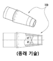
FIG. 1A shows a bi-prism angle (60 degrees) in two views of a Goldmann applanation tonometer tip used to measure human eyes.
1B is a diagram illustrating a Goldmann applanation tonometry.
2A is a view showing that the surface of the cornea is flattened by the pressure provided by the tonometer tip.
Fig. 2b is a diagram showing the pressure-dependent position of the semi-circles representing the image of the planarized portion of the two corneal surfaces.
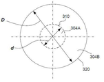
FIGS. 3A and 3B are a cross-sectional view and a top view illustrating an exemplary tonometer tip according to an embodiment of the present invention.
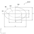
3C is a diagram showing another embodiment of the present invention.
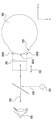
Fig. 4 is a diagram showing a method for measuring intraocular pressure as an embodiment of Figs. 3a and 3b. Fig.
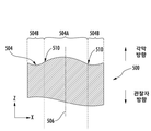
5A and 5B are a cross-sectional view and a top view, respectively, illustrating an exemplary tonometer tip according to another embodiment of the present invention.
Figure 6 shows a specific embodiment of the surface of the tonometer tip.
FIG. 7 shows the von Mises stress of the standard cornea induced in the measurement of the intraocular pressure by the embodiment of FIGS. 5A and 5B.
FIG. 8 provides diagrams illustrating the surface profile of the corneal surface before and after the applanation in the embodiment of FIGS. 5A and 5B.
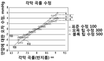
FIG. 9A provides a diagram illustrating the embodiment of FIGS. 5A and 5B, the embodiment of FIGS. 3A and 3B, and the error formed by corneal curvature when measuring intraocular pressure with a planar tip pressure gauge piece.
FIG. 9B provides a graphical representation of the embodiment of FIGS. 5A and 5B, showing the error formed by corneal rigidity when measuring intraocular pressure with a planar tip pressure gauge piece.
FIG. 9C provides a diagram illustrating the errors caused by corneal thickness, not zero, in the embodiment of FIGS. 5A and 5B, when measuring intraocular pressure with planar tip pressure gauge pieces.
10 is a contour map showing iso-pressure curves of the function of the corneal thickness for the standard cornea.
Figures 11A and 11B provide specific cross-sectional profiles for the embodiments of Figures 3A and 5A, respectively.
FIG. 12 is a diagram showing a reduction in average stress in the cornea that has been patched in the embodiment of FIGS. 3A, 3B and 5A, 5B versus a flat tip tonometer piece.
This application claims priority based on a provisional patent application, U.S. Serial No. 62 / 148,048, entitled " Ophthalmological Instrument ", issued April 15, 2015. This application is a continuation-in-part of U. S. Patent Application Serial No. 14 / 012,592, published as Pub. No. 2014/0073897. The disclosures of the above-mentioned applications are incorporated by reference.
The discussed invention solves the problems associated with measuring intraocular pressure in the eye with a Goldmann-type applanation tonometer (GAT) traditionally having a flat tip. The present invention eliminates the need to calibrate the measurement results by contributing to the thickness and stiffness of the cornea and at the same time the curvature of the cornea and the hardness of the cornea, Minimize errors in intraocular pressure measurement due to stress. These beneficial effects include an intraocular pressure gauge having a corneal contact surface comprising at least: i) a central bend portion and ii) a peripheral portion (generally axially symmetric) surrounding the central portion with a curvature having a sign opposite to that of the central portion Lt; / RTI > The central and peripheral portions of the tonometer tip surface may be tangentially joined along the lung plane curve. (In contrast to the design of a conventional tonometer member having a planar tip rather than a curved plane) - the center of the surface of the tip of a particular embodiment, counter-intuitively, The curvature of the portion preferably has a sign opposite to the sign of the curvature of the cornea. In accordance with embodiments of the present invention, ophthalmic device methods and devices are disclosed that include a corneal abutment member configured for use with a GAT platform constructed in accordance with the concepts of the present invention. Embodiments of the invention include an ophthalmic tool tip, a containment portion including a bi-prism, and a corneal contact surface configured to minimize corneal internal stress during corneal surface deformation and intracorneal pressure measurements.
For purposes of this specification and the appended claims, unless otherwise stated:
A plane curve is a curve defined in a plane. The lung plane curve is a curve that completely surrounds the area without end points. Preferably, the lung plane curve is defined in a plane across the axis. That is, the lung plane curves are defined in a plane that lies across or extends from the axis and extends in a direction perpendicular to the axis in certain cases. This improves the uniformity of corneal deformation when the corneal contact surface portion of the corneal contact member is pressed against the cornea.
In general, the surface of the corneal abutment member has a surface that deviates from a flat surface, and includes two differently curved surface portions, one of which is a concave surface portion and the other is a convex surface portion. For purposes of this specification and the appended claims, the radii of curvature, curvature, signs of curvature, and related terms are identified in accordance with mathematical meanings recognized and commonly used in the art. For example, the radius of curvature of a given curve at the point of the surface is generally defined as the radius of the circle closest to the curve at that point. The term curvature refers to the inverse of the radius of curvature. The definition of the curvature can be extended to have a positive or negative value (a value having a positive or negative sign) of the curvature. This selects the unit normal vector along the curve, sets the curvature of the curve to a positive sign if the curve is in the normal direction selected, and assigns a negative sign if it goes away in the normal direction. For the purposes of this disclosure and the appended claims, the sign of a given curvature is defined according to this convention. For these and other definitions of mathematical terms, the reader is referred to standard references for mathematics, such as I.N. Bronstein, K.A. Semendyaev, a reference to mathematics for engineers and university students, Science, 1981 (or any other edition).
Throughout this description, it is understood that "one embodiment", "an embodiment", "an embodiment", or similar term is intended to cover at least one embodiment of the invention, . Accordingly, the appearances of the phrases "in one embodiment "," in an embodiment "and similar language throughout this specification may refer to the same embodiment but are not necessarily so. It is to be understood that any portion of the disclosure, itself and in connection with the figures, does not provide a complete and complete description of the invention. It is to be understood that within the present disclosure, the embodiments have been described in a manner that enables the described clear and clear specifications, but it will be understood that the embodiments may be variously combined or separated without departing from the scope of the invention. In particular, it will be understood that all features described herein are applicable to all aspects of the invention.
When referring to the corresponding drawings in the present disclosure (where like numbers refer to the same or similar elements wherever possible), the structural elements shown are not to scale proportionally, and certain elements may be referred to other elements for emphasis and understanding Can be expanded. It is to be understood that the full disclosure of all features of the present invention is not limited to a single figure. In other words, a given drawing generally does not describe only some features of the invention, generally all features. BRIEF DESCRIPTION OF THE DRAWINGS The accompanying drawings, which are incorporated in and constitute a part of the specification, illustrate embodiments of the invention and, together with the description, serve to explain the principles of the invention. Does not include all elements or all features. Those of ordinary skill in the art will recognize that the invention may be practiced without one or more of the specific features, elements, components, structures, details, or characteristics, or without the use of other methods, components, materials, Thus, while specific details of embodiments of the present invention are not necessarily drawn to each and every individual drawing illustrating such an embodiment, the presence of that particular detail in the drawings may be implied, unless the context requires otherwise. have. In other instances, well-known structures, details, materials, or acts may not be shown or described in detail in order to avoid obscuring aspects of an embodiment of the invention being discussed. Furthermore, the single features, structures, or characteristics described herein may be combined in any suitable manner in one or more additional embodiments.
Also, where a schematic flow chart is included, the depicted sequence and indicated steps of the logic flow represent one embodiment of the proposed method. Other steps and sequences of functions, logic or effects equivalent to one or more steps or portions thereof in the illustrated method may be considered. The order in which a processing step or a particular method occurs without losing generality may or may not strictly adhere to the order of the indicated step.
It is intended that the invention recited in the claims appended hereto be appended to the full disclosure in addition to the features disclosed in the prior art referenced.
For the purposes of this specification and the appended claims, the use of the terms "substantially", "roughly", "approximately" and similar terms in connection with descriptors of values, elements, Is intended to emphasize the stated value, element, nature or characteristic but is not necessarily precisely described, but may be considered for practical purposes as described by one of ordinary skill in the art. The terms "most", "primarily", "substantially", "largely", "essentially", "largely or substantially", "not necessarily entirely" Quot; and < / RTI > particular features or descriptors so that the scope is understood by those skilled in the art. The use of these terms to describe a selected feature or concept does not imply or explicitly provide a basis for indefiniteness and a basis for numerical qualification of a descriptor or a particular feature. As is understood by those of ordinary skill in the art, actual deviations of the exact values or values, elements, or attributes of the described and described features may vary within the ranges specified by typical experimental measurement errors when using accepted measurement methods in the art . For example, a reference to a vector or line or plane that is substantially parallel to a baseline or plane extends along such vector or line or axis, and the direction or axis of the reference line or plane is the same or very close From 0 to 15 degrees, more preferably from 0 to 10 degrees, even more preferably from 0 to 5 degrees, most preferably from the reference direction or axis that is deemed substantially typical in the art The term "substantially rigid" when referring to a housing or structural element that provides mechanical support for the mechanism in question generally refers to a structure or element that provides structural support for such structures Refers to a structural element having a greater stiffness than a device supported by the element. As another example, the use of the term "substantially planar" with respect to a particular surface may be such that the surface may have unflatness and / or roughness that is sized and expressed, as generally understood by one of ordinary skill in the art . For example, the terms "approximately" and "approximate" when used in reference to a numerical value refer to a range of ㅁ 20%, more preferably 10 10%, even more preferably ㅁ 5% Preferably 2%.
The term "surface" is used to denote the boundaries of two media, boundaries, or spatial boundaries of a tangible element, according to its technical and scientific meaning. It has length and width but does not have thickness and is understood as the skin of the body (with a thickness of zero).
Terms such as " pressure ting, " "planarizing "," planarizing "and the like generally refer to an action process in which the surface curvature of a subject is reduced, (Creating a surface that is completely flat or at least curvature reduced compared to the initial value of the surface).
In addition, the following disclosure may describe features of the invention with reference to the corresponding drawings, wherein like numerals represent like or similar elements as possible. In the drawings, the structural elements shown are not generally scaled down proportionally, and certain elements are enlarged relative to other elements for emphasis and understanding. It is to be understood that the drawings are not intended to be exhaustive or to fully illustrate the true features of the invention. In other words, a given drawing generally does not describe only some features of the invention, generally all features. To simplify a given drawing and discussion, and to lead a discussion to a particular element presented in the drawing, a given portion of a disclosure, including a given drawing and a description referring to such a drawing, generally includes all elements of a particular view, ≪ / RTI > does not include all features that may be displayed in the display. It will be appreciated by those of ordinary skill in the art that the present invention may be practiced with one or more specific features, elements, components, structures, details or features, or with other methods, components, materials, Thus, although specific details of embodiments of the present invention are not necessarily drawn to every individual drawing illustrating such embodiments, the presence of such details of the drawings may be implied, unless the context requires otherwise . In other instances, well-known structures, details, materials, or acts may not be shown or described in detail in a given drawing in order to obscure the vague aspects of the embodiment of the invention being discussed. Furthermore, the single features, structures, or characteristics described herein may be combined in any suitable manner in one or more additional embodiments.
General considerations
Tonomometry is a non-invasive procedure performed by eye care professionals to determine intraocular fluid pressure (IOP), the intraocular pressure (IOP). It is an important test to evaluate patients at risk from glaucoma, a disease that causes the patient's visual impairment. In applanation tonometry, when a plane is pressed against a closed sphere with an internal pressure, Imbert-Fick says equilibrium is achieved when the force acting on the sphere is balanced by the sphere's internal pressure against the contact surface According to the hypothesis, the intraocular pressure is deduced from the force necessary to planarize (constrain) a constant, predefined area of the cornea. In other words, the pressure P in a flexible, elastic (and possibly infinitely thin) sphere is similar to the external force f, P = f / A, which is required to planarize a portion of the sphere normalized to the area A of the smoothed region . Thus, a transparent pressure member having a planar contact surface (such as, for example, the
Prior to performing the measurement, a local anesthetic (e.g., proxymecaine) is typically introduced into the surface of the eye (e.g., in the form of eye drops) because the pressure member contacts the cornea. During the measurement, the eye is illuminated with blue light (eg, light transmitted from a lamp equipped with a blue filter). In the area of contact between the corneal surface and the pressure member, a tear film (containing fluorescein and having a greenish hue when illuminated with blue light) is moved as a result of the contact, resulting in a boundary between the flat and curved regions of the cornea Is easily identifiable. The contact pressure required to flatten is used as a measure of the intraocular pressure.
The classic Goldmann tonometer (see Example 114 of FIG. 1B) has a transparent
The observer-inspector uses an optical filter (typically a cobalt blue filter) to view the two image components formed through the pitching tip 100 (shown as semicircular 210A, 210B in FIG. 2B). The force exerted on the
Some measurement errors occur because the thickness of the cornea is not zero, unlike the ideal sphere. If the cornea is thinner than the mean, the IOP is generally evaluated as low, whereas the mean corneal thickness is higher than the actual value. In order to offset the non-zero stiffness of the cornea of the actual IOP and to peal a portion of the cornea, additional force is required that can not be calculated as the actual intraocular pressure. The study revealed a correlation between corneal thickness and corneal stiffness. If so, the cornea with a thickness and stiffness of the cornea that is not zero induces an error in the measurement of the intraocular pressure. Therefore, in order to reduce the intraocular pressure measurement error, the value of the force applied to the cornea initially measured should be corrected based on the second measurement of the corneal thickness (measured by the keratometer) The accuracy of the correlation between thickness and hardness characteristics is presumed, but it is inherently inaccurate (due to age, corneal diameter, corneal curvature, and effects of various ocular diseases).
Until now, the additional cause of unknown measurement errors is the contribution of non-zero corneal curvature. The effect of corneal curvature on the accuracy of the intraocular pressure measurement was assessed by measuring the difference between the displaced eye-fluid volume and / or the original volume of the eye after the corneal area was flattened, or the two factors (Liu and Roberts, Effect of corneal biomechanical properties, J. Cataract Refract. Surg., 31, 146-155, January 2005). The effect of corneal curvature is independent of intraocular pressure, but it shows an important factor in the force transmitted from the eyeball to the tonometer tip in contact with the eye.
Finally, due to the fact that the conventional flat tip prism is brought into contact with the flattened cornea by "flattening" it, the "cornea flapping" procedure of conventional intraocular pressure measurement forms a sort of "kink" on the corneal surface . This "kink" reveals a corneal area in which the curvature of the partially edged cornea changes at a very high rate. As can be appreciated, this "kinked" region lies near the perimeter of the corneal edged portion and defines the spatial transition between the edged portion and the still curved portion that is not in contact with the cornea and the flat end of the glaucoma. In other words, in the "kinked" region, the secondary derivative of the function that represents the shape of the partially corneal cornea is very high and the cornea is greatly distorted, resulting in intracorporeal stress (the force and pressure exerted on the tip of the tonometer , Which is not related to intraocular pressure and adds an error to the measurement).
In particular, there is no conclusive and consistent data on the size of the biomechanical properties of the cornea to date. Wrong intraocular pressure - the exact amount of correction required, but indeed unclear - causes the risk of misdiagnosis and misses or delays detection of eye disease. Therefore, measurement techniques and systems are needed to increase the accuracy and accuracy of IOP results. By using the embodiments of the present invention, by increasing the accuracy of the intraocular pressure measurement (e.g., performed using the Goldmann applanation tonometry), the need for corneal thickness assisted measurement is eliminated, the overall cost is reduced, the quality of the ophthalmic treatment is improved Improve the quality of treatment. In addition, the use of embodiments of the present invention minimizes the contribution of corneal curvature to the intraocular pressure measurement procedure and intraocular stress caused by such procedures in the eye.
3A, 3B, 3C and 5A, 5B, non-limiting specific examples of an anomalous pressure tip formed in accordance with the teachings of the present invention are discussed.
Example 1
In Figures 3A and 3B, for example, an associated
At the periphery of the
In operation, the central recessed
Although the
In one embodiment and with further reference to Figures 3A and 3B, the
Example 2
3A and 3B, the
In the particular example shown in the top view of Figure 3C, the corneal contact surface 350 thus constructed has a footprint 352 defined as a flat ellipse perpendicular to the z-axis. The surface 350 includes a central substantially
The embodiment shown in FIG. 3C is suitable for facilitating the intraocular pressure measurement of a patient having an interlabial feature such that the observer-examiner is not necessarily able to accommodate the symmetrically structured corneal contact surface of the embodiment of FIGS. 3A and 3B. When the embodiment of the present invention represented by Fig. 3C is actually used, the area of the cornea to be patched remains substantially the same as the area corresponding to the embodiment of Fig. 3B. The lateral dimension of the elliptical footprint corresponding to 354A accommodating between narrow eyelids (partially closed eyelids) is reduced, but the orthogonal dimension of the footprint (along the eyelids) is increased compared to the diameter of the
Generally, the corneal contact surface of the
Example 3
Figures 5A and 5B schematically illustrate a
In operation, the central
Although the
In one embodiment and with further reference to the embodiment of Figures 5A and 5B, the
An associated
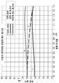
The profile of the
Polynomial optimization of
The degree to which the mean corneal profile changes when it comes into contact with the
Example 4
In an embodiment (not shown), the
In order to illustrate the operational advantages of the tonometer tip constructed in accordance with the idea of the present invention, the shape of the corneal contact surface of the tip of the device of the present invention may also be evaluated within a range of parameters that cause errors in intraocular pressure measurements. Among these parameters, corneal curvature (6-9 mm 95%; 6 mm very sharp corneal curvature) and corneal elastic modulus (0.1-0.9 MPa 95%, 0.9 MPa very hard cornea), corneal thickness (450-700 microns 95 % And tear film thickness (0-1 mm 95%).
Reduced measurement error due to corneal curvature by use of an embodiment of the present invention . The IOP correction values to be taken into consideration are calculated using the Finite Element Method (FEM), which is caused by the presence of corneal curvature. The IOP correction values to be considered are the normal flat tip corneal contact member (100, data and linear fitting 910) (300, data and linear fitting 920) and an embodiment (500, data and linear fitting 920) of the present invention. The radius of the corneal curvature varied from 6.8 to 9.4 mm to accommodate variations in mean, standard corneal curvature and empirically known corneal curvature. It will be appreciated by one of ordinary skill in the art that an intraocular pressure measurement performed with a calibrated tonometer tip (such as 300 or 500) according to an embodiment of the present invention imposes an eye stress on the cornea that is less than the intraocular pressure performed with a flat tonometer, The 300th and 500th percentile of the error produced by the corneal curvature in the measured intraocular pressure is less. For example, when considering a particular cornea with a 9 mm radius, the intraocular pressure correction that should be introduced to account for corneal curvature when performing measurements with the
Decrease of measurement error due to corneal hardness according to the embodiment of the present invention . On the other hand, when dealing with the elastic modulus of the corneal composite with respect to the intraocular pressure measurement error, the range of elastic modulus of about 0.1 MPa to about 0.9 MPa, which is known empirically, should be considered. 9B shows that when the corneal contact surface of the tonometer tip is constructed according to the idea of embodiment 500 (a correction amount to the measured intraocular pressure value required to compensate for the error caused by corneal stiffness) is substantially reduced ≪ / RTI > The calculation was performed with a finite element method (FEM) for the cornea with a thickness of 545 micrometers (the corneal thickness for a typical cornea from about 475 micrometers to about 640 micrometers provides a median value in a range that is substantially common) . For known individual differences in corneal stiffness, the use of an optimized tonometer tip constructed in accordance with the principles of the above example (compared to the conventional standard of a flat tip) reduces the error by as much as 2 mmHg.
Decrease of measurement error due to corneal thickness according to the embodiment of the present invention . The plot of Figure 9c shows the results of in vivo clinical comparisons of the errors introduced in the intraocular pressure measurements by Examples 100 and 500 of the tonometer tip. A clear tendency towards a substantial reduction in error can be observed when the intraocular pressure measurement is performed with the tonometer tip constructed in accordance with the idea of the present invention. As defined by the use of the tonometer tip constructed in accordance with the idea (s) of the present invention, a substantially observed reduction in error of less than 2 mmHg due to corneal thickness is comparable to the result during measurements made with a flat surface meter tip Time-mathematical model (linear fit).
FIG. 10, which is an iso-pressure curve plotted using a finite element method (FEM) for a standard cornea, shows the effect of standard corneal thickness on the value of the intraocular pressure (IOP) (1010) (Shown as a value in block 1020). For example, for a typical intraocular pressure of about 16 mmHg, the measured intraocular pressure will exceed the actual intraocular pressure due to an error of about 1.5 mmHg to 2.0 mmHg.
It is worth noting that the practical possibility of extreme eye characteristics that contribute most to the measurement error of Goldmann applanation tonometry is noteworthy. These features include a steep cornea with a radius of 6 mm, a hard cornea 0.9 MPa, a cornea with a central thickness of 700 microns, and a zero tear film. To this end, FIG. 11A provides the parameters of the specific design of the rotationally symmetric version of the
From the above discussion, the key to devising an optimized tonometer tip is the minimization of intra-corneal stress during companion deformation during intraocular pressure measurements. Figure 12 shows additional guidance on the advantages provided by
The schematic diagram of FIG. 4 shows a process of inspecting the
With further reference to Figure 4, some components of the Goldmann applanation tonometry (GAT) are omitted for simplicity of illustration. The path of the light traversing the
The particular values selected to illustrate the example embodiments described with reference to Figures 3A, 3B, and 4 may vary over a wide range to suit generally different applications. It will be understood by those of ordinary skill in the art that modifications and variations to the illustrated embodiments may be made without departing from the inventive concepts disclosed herein. Both the central recessed surface portion of the corneal contact surface and the associated peripheral surface portion may be spatially continuous without disturbance (e.g.,
Overall, the use of an anomaly tip configured to include a curved surface with a corneal contact surface deviating from a planar flat surface and having two curved surfaces with opposite signs as described above, (CCT), corneal hardness or hardness, corneal curvature, and / or intracorneal stress, in order to improve the accuracy of the intraocular pressure measurement compared to that of the cornea .
It is intended that the invention as recited in the claims appended hereto be assessed in the light of the present disclosure, including the features disclosed in the prior art to which reference has been made. Accordingly, the present invention should not be construed as limited to the disclosed embodiment (s).
100: Probe tip 114: Goldman IOP
116: Tonometer body 120: cornea
210A, 210B: semicircle
300: a tip according to an embodiment of the present invention, a corneal contact member
304:
304B: Peripheral surface portion, peripheral ring portion
306: Axis 310: Pulse curve, boundary
320: perimeter, curve, 326: vertex
354A: surface portion
354B: Peripheral ring portion, peripheral surface portion
350: corneal contact surface, surface
352: Footprint 400: Eye
420: light source 430: observer
440: arrow 500: embodiment of the present invention, apparatus
504: surface, corneal contact surface
504A: central surface portion, central convex surface portion
504B: peripheral concave portion, peripheral surface portion
506: axis 510: edge, curve, closed curve
520: around 604: lowest point, bottom
1010: Equilibrium curve 1020: Block
Claims (21)
A corneal contact member and a front surface dimensioned to contact the cornea of the eye during the measurement,
Wherein the front surface comprises a corneal contact surface portion defined by a central portion of the front surface of the corneal abutment member,
Wherein the corneal contact surface portion is curved at a non-zero curvature and is bent to reduce errors due to at least the curvature of the cornea during the measurement,
And a peripheral surface portion surrounding the curved contact surface portion and abuttingly abutting the corneal contact surface portion along the lung planar curve.
Wherein the corneal abutment member has a longitudinal axis,
Wherein the lung plane curve is defined in a plane transverse to the axis.
When the cornea of the eye has a first curvature having a first sign,
Wherein the corneal contact surface portion has a second curvature having a second sign opposite to the first sign,
Said peripheral surface portion having a third curvature of a third sign,
And the third code is opposite to the second code.
Wherein the front surface is formed such that the sign of the first curvature changes in a surface area defined by the ring when the corneal abutment member is pressed against the cornea.
Wherein the cornea of the eye has a first curvature having a first sign,
Wherein the curved contact surface portion has a second curvature having a second sign that is the same as the first sign,
Wherein the peripheral surface portion has a third curvature of a third sign and the third sign is opposite the second sign.
Wherein the curved contact surface portion is substantially co-operative with a surface of the cornea.
Wherein the front surface is configured to planarize a portion of the cornea when the corneal abutment member is pressed against the cornea during operation and wherein the planarized portion of the cornea is defined as an area that is symmetrical with respect to the axis.
The mechanism comprises:
An optical prism in the body of the corneal abutment member,
And a light source positioned to transmit light through the prism toward the front surface.
Wherein the corneal contact surface portion defines a portion of the spherical surface and wherein the corneal contact surface portion has no opening therethrough.
Wherein said front surface is axisymmetric with respect to said axis.
The device is composed of a tonometer.
The apparatus further comprises a housing element having an outer conical surface, wherein the corneal abutment member is secured to the housing.
A cornea abutment member comprising a front surface dimensioned to contact a first portion of the cornea of an eye,
The front surface is rotationally symmetric with respect to the axis and the front surface includes a portion of the corneal contact surface defining a portion of the spherical surface without an opening,
Wherein the corneal contact surface portion has a first curvature of a first sign opposite to the sign of the keratometry;
A curvature surrounding surface surrounding the corneal contact surface portion and joined together along a closed curve defined in a plane transverse to the axis with the corneal contact surface portion and having a second curvature having a second sign equal to a sign of the curvature of the cornea, Appliances containing parts.
Wherein,
Wherein the corneal abutment member is formed to oppose a portion of the cornea when the corneal abutment member is pressed against the cornea in operation, and wherein the edged portion of the cornea is defined by a ring.
Wherein the front surface is dimensioned to minimize intracrachicular stress in the tapered portion of the cornea.
The mechanism comprises:
Further comprising an optical prism in the body of the corneal abutment member and a light source arranged to transmit light through the prism toward the front face.
Pressing the corneal contact member against the cornea to make contact between the corneal contact surface and the cornea in order to minimize the error caused by the curvature of the cornea during the measurement;
Forming an optical image of the cornea with the light traversing the corneal contact and the corneal contact member; And
Determining a value of intraocular pressure from imaging data representative of the optical image.
Wherein the pressing comprises pressing the central bend against the cornea, wherein the curvature of the central bend and the curvature of the cornea have opposite signs.
Wherein the curvature of the central curved portion and the curvature of the peripheral surface portion have different signs.
The method comprises:
Wherein the step of calibrating the imaging data to compensate for at least one of thickness and stiffness of the cornea is not performed.
Wherein the pressing comprises:
And pressing the corneal abutment member wherein the peripheral surface portion abuts the central curved portion along a lung plane curve.
Applications Claiming Priority (3)
| Application Number | Priority Date | Filing Date | Title |
|---|---|---|---|
| US201562148048P | 2015-04-15 | 2015-04-15 | |
| US62/148,048 | 2015-04-15 | ||
| PCT/US2015/047134 WO2016167827A1 (en) | 2015-04-15 | 2015-08-27 | Optical instrument |
Publications (1)
| Publication Number | Publication Date |
|---|---|
| KR20170139063A true KR20170139063A (en) | 2017-12-18 |
Family
ID=54066222
Family Applications (1)
| Application Number | Title | Priority Date | Filing Date |
|---|---|---|---|
| KR1020177032827A KR20170139063A (en) | 2015-04-15 | 2015-08-27 | Optical instrument |
Country Status (10)
| Country | Link |
|---|---|
| US (1) | US20180303341A1 (en) |
| EP (1) | EP3282926A1 (en) |
| JP (1) | JP2018516722A (en) |
| KR (1) | KR20170139063A (en) |
| CN (1) | CN107529984A (en) |
| AU (1) | AU2015390959A1 (en) |
| BR (1) | BR112017022027A2 (en) |
| CA (1) | CA2981941A1 (en) |
| MX (1) | MX2017013155A (en) |
| WO (1) | WO2016167827A1 (en) |
Families Citing this family (5)
| Publication number | Priority date | Publication date | Assignee | Title |
|---|---|---|---|---|
| US11026576B2 (en) | 2015-04-15 | 2021-06-08 | Cats Tonometer, Llc | Reducing errors of tonometric measurements by using a tonometer tip with a curved cornea-contacting surface |
| ES2662697B1 (en) * | 2016-10-03 | 2019-05-06 | Alvarez Maria Iglesias | APPLICATION TONOMETER |
| AU2018385598B2 (en) * | 2017-12-12 | 2021-01-28 | Cats Tonometer, Llc | Reducing errors of optical measurements of internal pressure of a body performed with an optical member in contact with the body |
| US20220015631A1 (en) * | 2020-07-17 | 2022-01-20 | Reichert, Inc. | Single-use contact tip for tonometer |
| WO2023023167A2 (en) | 2021-08-19 | 2023-02-23 | Cats Tonometer, Llc | Transducer probes for ophthalmological instruments and uses thereof |
Family Cites Families (9)
| Publication number | Priority date | Publication date | Assignee | Title |
|---|---|---|---|---|
| GB862920A (en) * | 1957-06-29 | 1961-03-15 | Haag Streit A G | Improvements in apparatus for measuring the intraocular or tonometric pressure of aneye |
| NL7408214A (en) * | 1974-06-19 | 1975-12-23 | Arend Hagedoorn Apollolaan 129 | Human eye-pressure measuring equipment - has additional membrane with micrometer pressure adjustment for tonometer chamber |
| US4523597A (en) * | 1982-12-29 | 1985-06-18 | Minolta Camera Kabushiki Kaisha | Apparatus and method for measuring the intraocular pressure of an eyeball and auxiliary device for using therewith |
| US5619289A (en) * | 1993-03-31 | 1997-04-08 | Permeable Technologies, Inc. | Multifocal contact lens |
| JP2003111732A (en) * | 2001-10-08 | 2003-04-15 | Reiko Segawa | Contact-type applanation tonometry and tonometer |
| PL2397068T3 (en) * | 2010-06-21 | 2020-11-16 | Oculus Optikgeräte GmbH | Analysis of intraocular pressure |
| US9585578B2 (en) * | 2011-12-02 | 2017-03-07 | Third Eye Diagnostics, Inc. | Devices and methods for noninvasive measurement of intracranial pressure |
| US9078612B2 (en) * | 2011-12-02 | 2015-07-14 | Third Eye Diagnostics, Inc. | Devices and methods for noninvasive measurement of intracranial pressure |
| US10463251B2 (en) * | 2012-09-10 | 2019-11-05 | Cats Tonometer, Llc | Ophthalmological instrument |
-
2015
- 2015-08-27 JP JP2018506077A patent/JP2018516722A/en active Pending
- 2015-08-27 EP EP15760576.7A patent/EP3282926A1/en not_active Withdrawn
- 2015-08-27 CA CA2981941A patent/CA2981941A1/en not_active Abandoned
- 2015-08-27 WO PCT/US2015/047134 patent/WO2016167827A1/en active Application Filing
- 2015-08-27 AU AU2015390959A patent/AU2015390959A1/en not_active Abandoned
- 2015-08-27 BR BR112017022027A patent/BR112017022027A2/en not_active Application Discontinuation
- 2015-08-27 US US15/565,244 patent/US20180303341A1/en not_active Abandoned
- 2015-08-27 MX MX2017013155A patent/MX2017013155A/en unknown
- 2015-08-27 CN CN201580078744.8A patent/CN107529984A/en active Pending
- 2015-08-27 KR KR1020177032827A patent/KR20170139063A/en not_active Application Discontinuation
Also Published As
| Publication number | Publication date |
|---|---|
| US20180303341A1 (en) | 2018-10-25 |
| BR112017022027A2 (en) | 2018-07-03 |
| EP3282926A1 (en) | 2018-02-21 |
| WO2016167827A1 (en) | 2016-10-20 |
| MX2017013155A (en) | 2018-04-24 |
| CN107529984A (en) | 2018-01-02 |
| AU2015390959A1 (en) | 2017-10-26 |
| CA2981941A1 (en) | 2016-10-20 |
| JP2018516722A (en) | 2018-06-28 |
Similar Documents
| Publication | Publication Date | Title |
|---|---|---|
| US11484203B2 (en) | Tonometer tip and use of same | |
| US20210298597A1 (en) | Reducing errors of tonometric measurements by using a tonometer tip with a curved cornea-contacting surface | |
| KR20170139063A (en) | Optical instrument | |
| Valbon et al. | Ocular biomechanical metrics by CorVis ST in healthy Brazilian patients | |
| US8388130B2 (en) | Non-deforming contact lens | |
| CN108508630B (en) | Lens design machine and related method | |
| KR20060021331A (en) | Contact lens with shaped periphery | |
| CN110785113B (en) | Method for determining the position of the center of rotation of the eye of a subject's eye and related device | |
| Garcia-Feijoo et al. | New technologies for measuring intraocular pressure | |
| McCafferty et al. | Goldmann tonometer prism with an optimized error correcting applanation surface | |
| Ambrósio Jr et al. | Biomechanics of Keratoconus | |
| JP7003317B2 (en) | Reduction of errors in optical measurement of internal pressure of the body performed by optical members in contact with the body | |
| US20070123768A1 (en) | Ophthalmic instruments, systems and methods especially adapted for conducting simultaneous tonometry and pachymetry measurements | |
| EP4071544B1 (en) | Contact lens manufacturing method and contact lens | |
| EP3495873A1 (en) | Orthokeratology lens | |
| KR20220006730A (en) | Portable IOP(IntraOcular Pressure) measurement based on cornea structural changes and its instrumentation | |
| KR101538129B1 (en) | Standard lens for eye refractometer | |
| Ferreri et al. | Felicia Ferreri, Rosa Minniti, Alessandra Polimeni, Lucia Zavettieri, Giuseppina Ferreri | |
| WO2017163055A1 (en) | Improvements in or relating to contact lenses | |
| Navarro et al. | The changes of shape of the human cornea with age |
Legal Events
| Date | Code | Title | Description |
|---|---|---|---|
| E902 | Notification of reason for refusal | ||
| E601 | Decision to refuse application |