KR20170137132A - Pressure monitoring methods including boiling detection - Google Patents
Pressure monitoring methods including boiling detection Download PDFInfo
- Publication number
- KR20170137132A KR20170137132A KR1020177031812A KR20177031812A KR20170137132A KR 20170137132 A KR20170137132 A KR 20170137132A KR 1020177031812 A KR1020177031812 A KR 1020177031812A KR 20177031812 A KR20177031812 A KR 20177031812A KR 20170137132 A KR20170137132 A KR 20170137132A
- Authority
- KR
- South Korea
- Prior art keywords
- pressure
- tank
- boiling
- liquid
- valve
- Prior art date
Links
- 238000009835 boiling Methods 0.000 title claims abstract description 73
- 238000000034 method Methods 0.000 title claims abstract description 25
- 238000001514 detection method Methods 0.000 title claims description 19
- 238000012544 monitoring process Methods 0.000 title claims description 6
- 239000007788 liquid Substances 0.000 claims abstract description 68
- 239000000446 fuel Substances 0.000 claims description 9
- 230000003111 delayed effect Effects 0.000 claims description 2
- 238000010586 diagram Methods 0.000 description 6
- 239000007789 gas Substances 0.000 description 6
- 238000010926 purge Methods 0.000 description 4
- 238000011109 contamination Methods 0.000 description 3
- OKTJSMMVPCPJKN-UHFFFAOYSA-N Carbon Chemical compound [C] OKTJSMMVPCPJKN-UHFFFAOYSA-N 0.000 description 2
- 238000002485 combustion reaction Methods 0.000 description 2
- 239000000356 contaminant Substances 0.000 description 2
- 238000001704 evaporation Methods 0.000 description 2
- 230000008020 evaporation Effects 0.000 description 2
- 239000002828 fuel tank Substances 0.000 description 2
- 239000000463 material Substances 0.000 description 2
- 230000003213 activating effect Effects 0.000 description 1
- 230000033228 biological regulation Effects 0.000 description 1
- 230000005540 biological transmission Effects 0.000 description 1
- 238000012790 confirmation Methods 0.000 description 1
- 230000007423 decrease Effects 0.000 description 1
- 230000001419 dependent effect Effects 0.000 description 1
- 230000001627 detrimental effect Effects 0.000 description 1
- 238000001914 filtration Methods 0.000 description 1
- 238000012423 maintenance Methods 0.000 description 1
- 238000004519 manufacturing process Methods 0.000 description 1
- 230000008929 regeneration Effects 0.000 description 1
- 238000011069 regeneration method Methods 0.000 description 1
- 230000004043 responsiveness Effects 0.000 description 1
- 229920006395 saturated elastomer Polymers 0.000 description 1
- 238000007789 sealing Methods 0.000 description 1
- 238000012546 transfer Methods 0.000 description 1
- 238000013022 venting Methods 0.000 description 1
Images


Classifications
-
- G—PHYSICS
- G05—CONTROLLING; REGULATING
- G05D—SYSTEMS FOR CONTROLLING OR REGULATING NON-ELECTRIC VARIABLES
- G05D16/00—Control of fluid pressure
- G05D16/02—Modifications to reduce the effects of instability, e.g. due to vibrations, friction, abnormal temperature, overloading or imbalance
-
- B—PERFORMING OPERATIONS; TRANSPORTING
- B60—VEHICLES IN GENERAL
- B60K—ARRANGEMENT OR MOUNTING OF PROPULSION UNITS OR OF TRANSMISSIONS IN VEHICLES; ARRANGEMENT OR MOUNTING OF PLURAL DIVERSE PRIME-MOVERS IN VEHICLES; AUXILIARY DRIVES FOR VEHICLES; INSTRUMENTATION OR DASHBOARDS FOR VEHICLES; ARRANGEMENTS IN CONNECTION WITH COOLING, AIR INTAKE, GAS EXHAUST OR FUEL SUPPLY OF PROPULSION UNITS IN VEHICLES
- B60K15/00—Arrangement in connection with fuel supply of combustion engines or other fuel consuming energy converters, e.g. fuel cells; Mounting or construction of fuel tanks
- B60K15/03—Fuel tanks
- B60K15/035—Fuel tanks characterised by venting means
- B60K15/03504—Fuel tanks characterised by venting means adapted to avoid loss of fuel or fuel vapour, e.g. with vapour recovery systems
-
- B—PERFORMING OPERATIONS; TRANSPORTING
- B60—VEHICLES IN GENERAL
- B60K—ARRANGEMENT OR MOUNTING OF PROPULSION UNITS OR OF TRANSMISSIONS IN VEHICLES; ARRANGEMENT OR MOUNTING OF PLURAL DIVERSE PRIME-MOVERS IN VEHICLES; AUXILIARY DRIVES FOR VEHICLES; INSTRUMENTATION OR DASHBOARDS FOR VEHICLES; ARRANGEMENTS IN CONNECTION WITH COOLING, AIR INTAKE, GAS EXHAUST OR FUEL SUPPLY OF PROPULSION UNITS IN VEHICLES
- B60K15/00—Arrangement in connection with fuel supply of combustion engines or other fuel consuming energy converters, e.g. fuel cells; Mounting or construction of fuel tanks
- B60K15/03—Fuel tanks
- B60K15/035—Fuel tanks characterised by venting means
- B60K15/03519—Valve arrangements in the vent line
-
- B—PERFORMING OPERATIONS; TRANSPORTING
- B60—VEHICLES IN GENERAL
- B60K—ARRANGEMENT OR MOUNTING OF PROPULSION UNITS OR OF TRANSMISSIONS IN VEHICLES; ARRANGEMENT OR MOUNTING OF PLURAL DIVERSE PRIME-MOVERS IN VEHICLES; AUXILIARY DRIVES FOR VEHICLES; INSTRUMENTATION OR DASHBOARDS FOR VEHICLES; ARRANGEMENTS IN CONNECTION WITH COOLING, AIR INTAKE, GAS EXHAUST OR FUEL SUPPLY OF PROPULSION UNITS IN VEHICLES
- B60K15/00—Arrangement in connection with fuel supply of combustion engines or other fuel consuming energy converters, e.g. fuel cells; Mounting or construction of fuel tanks
- B60K15/03—Fuel tanks
- B60K15/077—Fuel tanks with means modifying or controlling distribution or motion of fuel, e.g. to prevent noise, surge, splash or fuel starvation
-
- F—MECHANICAL ENGINEERING; LIGHTING; HEATING; WEAPONS; BLASTING
- F02—COMBUSTION ENGINES; HOT-GAS OR COMBUSTION-PRODUCT ENGINE PLANTS
- F02M—SUPPLYING COMBUSTION ENGINES IN GENERAL WITH COMBUSTIBLE MIXTURES OR CONSTITUENTS THEREOF
- F02M25/00—Engine-pertinent apparatus for adding non-fuel substances or small quantities of secondary fuel to combustion-air, main fuel or fuel-air mixture
- F02M25/08—Engine-pertinent apparatus for adding non-fuel substances or small quantities of secondary fuel to combustion-air, main fuel or fuel-air mixture adding fuel vapours drawn from engine fuel reservoir
- F02M25/0836—Arrangement of valves controlling the admission of fuel vapour to an engine, e.g. valve being disposed between fuel tank or absorption canister and intake manifold
-
- F—MECHANICAL ENGINEERING; LIGHTING; HEATING; WEAPONS; BLASTING
- F17—STORING OR DISTRIBUTING GASES OR LIQUIDS
- F17C—VESSELS FOR CONTAINING OR STORING COMPRESSED, LIQUEFIED OR SOLIDIFIED GASES; FIXED-CAPACITY GAS-HOLDERS; FILLING VESSELS WITH, OR DISCHARGING FROM VESSELS, COMPRESSED, LIQUEFIED, OR SOLIDIFIED GASES
- F17C13/00—Details of vessels or of the filling or discharging of vessels
- F17C13/002—Details of vessels or of the filling or discharging of vessels for vessels under pressure
-
- F—MECHANICAL ENGINEERING; LIGHTING; HEATING; WEAPONS; BLASTING
- F17—STORING OR DISTRIBUTING GASES OR LIQUIDS
- F17C—VESSELS FOR CONTAINING OR STORING COMPRESSED, LIQUEFIED OR SOLIDIFIED GASES; FIXED-CAPACITY GAS-HOLDERS; FILLING VESSELS WITH, OR DISCHARGING FROM VESSELS, COMPRESSED, LIQUEFIED, OR SOLIDIFIED GASES
- F17C13/00—Details of vessels or of the filling or discharging of vessels
- F17C13/02—Special adaptations of indicating, measuring, or monitoring equipment
- F17C13/025—Special adaptations of indicating, measuring, or monitoring equipment having the pressure as the parameter
-
- F—MECHANICAL ENGINEERING; LIGHTING; HEATING; WEAPONS; BLASTING
- F17—STORING OR DISTRIBUTING GASES OR LIQUIDS
- F17C—VESSELS FOR CONTAINING OR STORING COMPRESSED, LIQUEFIED OR SOLIDIFIED GASES; FIXED-CAPACITY GAS-HOLDERS; FILLING VESSELS WITH, OR DISCHARGING FROM VESSELS, COMPRESSED, LIQUEFIED, OR SOLIDIFIED GASES
- F17C13/00—Details of vessels or of the filling or discharging of vessels
- F17C13/04—Arrangement or mounting of valves
-
- G—PHYSICS
- G01—MEASURING; TESTING
- G01L—MEASURING FORCE, STRESS, TORQUE, WORK, MECHANICAL POWER, MECHANICAL EFFICIENCY, OR FLUID PRESSURE
- G01L19/00—Details of, or accessories for, apparatus for measuring steady or quasi-steady pressure of a fluent medium insofar as such details or accessories are not special to particular types of pressure gauges
- G01L19/08—Means for indicating or recording, e.g. for remote indication
- G01L19/083—Means for indicating or recording, e.g. for remote indication electrical
-
- B—PERFORMING OPERATIONS; TRANSPORTING
- B60—VEHICLES IN GENERAL
- B60K—ARRANGEMENT OR MOUNTING OF PROPULSION UNITS OR OF TRANSMISSIONS IN VEHICLES; ARRANGEMENT OR MOUNTING OF PLURAL DIVERSE PRIME-MOVERS IN VEHICLES; AUXILIARY DRIVES FOR VEHICLES; INSTRUMENTATION OR DASHBOARDS FOR VEHICLES; ARRANGEMENTS IN CONNECTION WITH COOLING, AIR INTAKE, GAS EXHAUST OR FUEL SUPPLY OF PROPULSION UNITS IN VEHICLES
- B60K15/00—Arrangement in connection with fuel supply of combustion engines or other fuel consuming energy converters, e.g. fuel cells; Mounting or construction of fuel tanks
- B60K15/03—Fuel tanks
- B60K2015/0321—Fuel tanks characterised by special sensors, the mounting thereof
-
- B—PERFORMING OPERATIONS; TRANSPORTING
- B60—VEHICLES IN GENERAL
- B60K—ARRANGEMENT OR MOUNTING OF PROPULSION UNITS OR OF TRANSMISSIONS IN VEHICLES; ARRANGEMENT OR MOUNTING OF PLURAL DIVERSE PRIME-MOVERS IN VEHICLES; AUXILIARY DRIVES FOR VEHICLES; INSTRUMENTATION OR DASHBOARDS FOR VEHICLES; ARRANGEMENTS IN CONNECTION WITH COOLING, AIR INTAKE, GAS EXHAUST OR FUEL SUPPLY OF PROPULSION UNITS IN VEHICLES
- B60K15/00—Arrangement in connection with fuel supply of combustion engines or other fuel consuming energy converters, e.g. fuel cells; Mounting or construction of fuel tanks
- B60K15/03—Fuel tanks
- B60K2015/03236—Fuel tanks characterised by special filters, the mounting thereof
-
- B—PERFORMING OPERATIONS; TRANSPORTING
- B60—VEHICLES IN GENERAL
- B60K—ARRANGEMENT OR MOUNTING OF PROPULSION UNITS OR OF TRANSMISSIONS IN VEHICLES; ARRANGEMENT OR MOUNTING OF PLURAL DIVERSE PRIME-MOVERS IN VEHICLES; AUXILIARY DRIVES FOR VEHICLES; INSTRUMENTATION OR DASHBOARDS FOR VEHICLES; ARRANGEMENTS IN CONNECTION WITH COOLING, AIR INTAKE, GAS EXHAUST OR FUEL SUPPLY OF PROPULSION UNITS IN VEHICLES
- B60K15/00—Arrangement in connection with fuel supply of combustion engines or other fuel consuming energy converters, e.g. fuel cells; Mounting or construction of fuel tanks
- B60K15/03—Fuel tanks
- B60K2015/03256—Fuel tanks characterised by special valves, the mounting thereof
- B60K2015/03269—Flap valves
-
- B—PERFORMING OPERATIONS; TRANSPORTING
- B60—VEHICLES IN GENERAL
- B60K—ARRANGEMENT OR MOUNTING OF PROPULSION UNITS OR OF TRANSMISSIONS IN VEHICLES; ARRANGEMENT OR MOUNTING OF PLURAL DIVERSE PRIME-MOVERS IN VEHICLES; AUXILIARY DRIVES FOR VEHICLES; INSTRUMENTATION OR DASHBOARDS FOR VEHICLES; ARRANGEMENTS IN CONNECTION WITH COOLING, AIR INTAKE, GAS EXHAUST OR FUEL SUPPLY OF PROPULSION UNITS IN VEHICLES
- B60K15/00—Arrangement in connection with fuel supply of combustion engines or other fuel consuming energy converters, e.g. fuel cells; Mounting or construction of fuel tanks
- B60K15/03—Fuel tanks
- B60K2015/03256—Fuel tanks characterised by special valves, the mounting thereof
- B60K2015/03302—Electromagnetic valves
-
- B—PERFORMING OPERATIONS; TRANSPORTING
- B60—VEHICLES IN GENERAL
- B60K—ARRANGEMENT OR MOUNTING OF PROPULSION UNITS OR OF TRANSMISSIONS IN VEHICLES; ARRANGEMENT OR MOUNTING OF PLURAL DIVERSE PRIME-MOVERS IN VEHICLES; AUXILIARY DRIVES FOR VEHICLES; INSTRUMENTATION OR DASHBOARDS FOR VEHICLES; ARRANGEMENTS IN CONNECTION WITH COOLING, AIR INTAKE, GAS EXHAUST OR FUEL SUPPLY OF PROPULSION UNITS IN VEHICLES
- B60K15/00—Arrangement in connection with fuel supply of combustion engines or other fuel consuming energy converters, e.g. fuel cells; Mounting or construction of fuel tanks
- B60K15/03—Fuel tanks
- B60K2015/03328—Arrangements or special measures related to fuel tanks or fuel handling
-
- B—PERFORMING OPERATIONS; TRANSPORTING
- B60—VEHICLES IN GENERAL
- B60K—ARRANGEMENT OR MOUNTING OF PROPULSION UNITS OR OF TRANSMISSIONS IN VEHICLES; ARRANGEMENT OR MOUNTING OF PLURAL DIVERSE PRIME-MOVERS IN VEHICLES; AUXILIARY DRIVES FOR VEHICLES; INSTRUMENTATION OR DASHBOARDS FOR VEHICLES; ARRANGEMENTS IN CONNECTION WITH COOLING, AIR INTAKE, GAS EXHAUST OR FUEL SUPPLY OF PROPULSION UNITS IN VEHICLES
- B60K15/00—Arrangement in connection with fuel supply of combustion engines or other fuel consuming energy converters, e.g. fuel cells; Mounting or construction of fuel tanks
- B60K15/03—Fuel tanks
- B60K15/035—Fuel tanks characterised by venting means
- B60K15/03504—Fuel tanks characterised by venting means adapted to avoid loss of fuel or fuel vapour, e.g. with vapour recovery systems
- B60K2015/03514—Fuel tanks characterised by venting means adapted to avoid loss of fuel or fuel vapour, e.g. with vapour recovery systems with vapor recovery means
-
- F—MECHANICAL ENGINEERING; LIGHTING; HEATING; WEAPONS; BLASTING
- F17—STORING OR DISTRIBUTING GASES OR LIQUIDS
- F17C—VESSELS FOR CONTAINING OR STORING COMPRESSED, LIQUEFIED OR SOLIDIFIED GASES; FIXED-CAPACITY GAS-HOLDERS; FILLING VESSELS WITH, OR DISCHARGING FROM VESSELS, COMPRESSED, LIQUEFIED, OR SOLIDIFIED GASES
- F17C2205/00—Vessel construction, in particular mounting arrangements, attachments or identifications means
- F17C2205/03—Fluid connections, filters, valves, closure means or other attachments
- F17C2205/0302—Fittings, valves, filters, or components in connection with the gas storage device
- F17C2205/0323—Valves
-
- F—MECHANICAL ENGINEERING; LIGHTING; HEATING; WEAPONS; BLASTING
- F17—STORING OR DISTRIBUTING GASES OR LIQUIDS
- F17C—VESSELS FOR CONTAINING OR STORING COMPRESSED, LIQUEFIED OR SOLIDIFIED GASES; FIXED-CAPACITY GAS-HOLDERS; FILLING VESSELS WITH, OR DISCHARGING FROM VESSELS, COMPRESSED, LIQUEFIED, OR SOLIDIFIED GASES
- F17C2205/00—Vessel construction, in particular mounting arrangements, attachments or identifications means
- F17C2205/03—Fluid connections, filters, valves, closure means or other attachments
- F17C2205/0302—Fittings, valves, filters, or components in connection with the gas storage device
- F17C2205/0341—Filters
-
- F—MECHANICAL ENGINEERING; LIGHTING; HEATING; WEAPONS; BLASTING
- F17—STORING OR DISTRIBUTING GASES OR LIQUIDS
- F17C—VESSELS FOR CONTAINING OR STORING COMPRESSED, LIQUEFIED OR SOLIDIFIED GASES; FIXED-CAPACITY GAS-HOLDERS; FILLING VESSELS WITH, OR DISCHARGING FROM VESSELS, COMPRESSED, LIQUEFIED, OR SOLIDIFIED GASES
- F17C2205/00—Vessel construction, in particular mounting arrangements, attachments or identifications means
- F17C2205/03—Fluid connections, filters, valves, closure means or other attachments
- F17C2205/0388—Arrangement of valves, regulators, filters
-
- F—MECHANICAL ENGINEERING; LIGHTING; HEATING; WEAPONS; BLASTING
- F17—STORING OR DISTRIBUTING GASES OR LIQUIDS
- F17C—VESSELS FOR CONTAINING OR STORING COMPRESSED, LIQUEFIED OR SOLIDIFIED GASES; FIXED-CAPACITY GAS-HOLDERS; FILLING VESSELS WITH, OR DISCHARGING FROM VESSELS, COMPRESSED, LIQUEFIED, OR SOLIDIFIED GASES
- F17C2250/00—Accessories; Control means; Indicating, measuring or monitoring of parameters
- F17C2250/03—Control means
- F17C2250/032—Control means using computers
-
- F—MECHANICAL ENGINEERING; LIGHTING; HEATING; WEAPONS; BLASTING
- F17—STORING OR DISTRIBUTING GASES OR LIQUIDS
- F17C—VESSELS FOR CONTAINING OR STORING COMPRESSED, LIQUEFIED OR SOLIDIFIED GASES; FIXED-CAPACITY GAS-HOLDERS; FILLING VESSELS WITH, OR DISCHARGING FROM VESSELS, COMPRESSED, LIQUEFIED, OR SOLIDIFIED GASES
- F17C2250/00—Accessories; Control means; Indicating, measuring or monitoring of parameters
- F17C2250/03—Control means
- F17C2250/036—Control means using alarms
-
- F—MECHANICAL ENGINEERING; LIGHTING; HEATING; WEAPONS; BLASTING
- F17—STORING OR DISTRIBUTING GASES OR LIQUIDS
- F17C—VESSELS FOR CONTAINING OR STORING COMPRESSED, LIQUEFIED OR SOLIDIFIED GASES; FIXED-CAPACITY GAS-HOLDERS; FILLING VESSELS WITH, OR DISCHARGING FROM VESSELS, COMPRESSED, LIQUEFIED, OR SOLIDIFIED GASES
- F17C2250/00—Accessories; Control means; Indicating, measuring or monitoring of parameters
- F17C2250/04—Indicating or measuring of parameters as input values
- F17C2250/0404—Parameters indicated or measured
- F17C2250/043—Pressure
- F17C2250/0434—Pressure difference
-
- F—MECHANICAL ENGINEERING; LIGHTING; HEATING; WEAPONS; BLASTING
- F17—STORING OR DISTRIBUTING GASES OR LIQUIDS
- F17C—VESSELS FOR CONTAINING OR STORING COMPRESSED, LIQUEFIED OR SOLIDIFIED GASES; FIXED-CAPACITY GAS-HOLDERS; FILLING VESSELS WITH, OR DISCHARGING FROM VESSELS, COMPRESSED, LIQUEFIED, OR SOLIDIFIED GASES
- F17C2250/00—Accessories; Control means; Indicating, measuring or monitoring of parameters
- F17C2250/06—Controlling or regulating of parameters as output values
- F17C2250/0689—Methods for controlling or regulating
-
- F—MECHANICAL ENGINEERING; LIGHTING; HEATING; WEAPONS; BLASTING
- F17—STORING OR DISTRIBUTING GASES OR LIQUIDS
- F17C—VESSELS FOR CONTAINING OR STORING COMPRESSED, LIQUEFIED OR SOLIDIFIED GASES; FIXED-CAPACITY GAS-HOLDERS; FILLING VESSELS WITH, OR DISCHARGING FROM VESSELS, COMPRESSED, LIQUEFIED, OR SOLIDIFIED GASES
- F17C2270/00—Applications
- F17C2270/01—Applications for fluid transport or storage
- F17C2270/0165—Applications for fluid transport or storage on the road
- F17C2270/0168—Applications for fluid transport or storage on the road by vehicles
Landscapes
- Engineering & Computer Science (AREA)
- Mechanical Engineering (AREA)
- Chemical & Material Sciences (AREA)
- Combustion & Propulsion (AREA)
- Life Sciences & Earth Sciences (AREA)
- Sustainable Development (AREA)
- Sustainable Energy (AREA)
- Transportation (AREA)
- General Engineering & Computer Science (AREA)
- Physics & Mathematics (AREA)
- General Physics & Mathematics (AREA)
- Fluid Mechanics (AREA)
- Automation & Control Theory (AREA)
- Cooling, Air Intake And Gas Exhaust, And Fuel Tank Arrangements In Propulsion Units (AREA)
- Filling Or Discharging Of Gas Storage Vessels (AREA)
- Measurement Of Levels Of Liquids Or Fluent Solid Materials (AREA)
Abstract
액체(6)를 담을 수 있는 밀봉된 탱크(2), 액체(6)로부터 나오는 증기를 포집할 수 있는 필터(3), 탱크(2)를 필터(3)에 연결하는 파이프(4), 및 파이프(4)를 선택적으로 차단하는 방식으로 배치된 차단 밸브(5)를 포함하는 탱크 조립체(1)에 대한 압력 제어 방법은 탱크(2)에 담긴 액체의 비등을 탐지하는 단계를 포함한다.A sealed tank 2 capable of containing liquid 6, a filter 3 capable of collecting the vapor from the liquid 6, a pipe 4 connecting the tank 2 to the filter 3, A method of controlling pressure for a tank assembly (1) comprising a shutoff valve (5) arranged in such a way as to selectively block the pipe (4) comprises the step of detecting the boiling of the liquid contained in the tank (2).
Description
본 발명은 액체 연료를 차량에 저장하는 데 사용되는 것과 같은 밀봉된 액체용 탱크에 관한 것으로서, 특히 이러한 탱크 내부의 압력을 제어하는 것과 연관된 문제에 관한 것이다.The present invention relates to a sealed liquid tank, such as one used to store liquid fuel in a vehicle, and more particularly to a problem associated with controlling the pressure within such a tank.
이러한 탱크를 손상시키지 않기 위해, 그 내부의 압력은 최대 한계 (초과) 압력보다 낮게 유지되어야 하며, 또한 최소 한계 (진공) 압력보다 높게 유지될 필요가 있다.In order not to damage these tanks, the pressure inside them must be kept below the maximum limit (over) pressure and also needs to be maintained above the minimum limit (vacuum) pressure.
탱크 내부의 압력은 통상적으로 탱크의 충전에 의해 부가되거나, 통상적으로 예를 들어 연료의 경우에 엔진을 위해 의도된 인출(withdrawal)에 의해 제거된 액체의 양에 의존하고, 또한 환경 조건: 대기압 및 온도에 의존한다. 온도와 연관된 하나의 어려움은 그것을 제어할 수 있는 능력 없이 진폭이 매우 클 수 있다는 것이다. 따라서, 예를 들어, 차량은 그 자체가 한 겨울에는 매우 낮은 온도를 받거나, 한 여름에는 매우 높은 온도를 받을 수도 있다.The pressure inside the tank is usually added by charging the tank or is typically dependent on the amount of liquid removed by the withdrawal intended for the engine in the case of fuel, It depends on the temperature. One difficulty associated with temperature is that the amplitude can be very large without the ability to control it. Thus, for example, a vehicle may itself receive very low temperatures in one winter, or very high temperatures in the summer.
연소 엔진과 자동차의 초창기에, 가능하게는 최대 한계 압력 및/또는 최소 한계 압력에서 정격된 적어도 하나의 밸브를 통해 야외로 배출시킴으로써 압력 제어가 수동적으로 해결되었다. 따라서, 탱크는 액체 내용물을 보유하기 위해 액체에 대해 밀봉되었지만, 야외로 배출시키기 위해 개방되거나 개방될 수 있으며, 가스가 통과하도록 허용한다. 진공 압력의 경우에, 공기는 외부에서 탱크 안으로 수용될 수 있으며, 초과 압력의 경우에, 가스는 둘 다의 경우에 2개의 한계 압력 사이에 포함된 수용 가능한 압력을 재설정하기 위해 탱크에서 외부로 빠져나올 수 있다.In the early days of the combustion engine and the vehicle, pressure control was manually solved by venting outdoors, possibly through at least one valve rated at a maximum critical pressure and / or a minimum critical pressure. Thus, the tank is sealed to the liquid to retain the liquid contents, but can be opened or opened to vent outdoors, allowing the gas to pass through. In the case of vacuum pressure, the air can be received from the outside into the tank, and in the case of excess pressure, the gas is forced out of the tank to reset the acceptable pressure contained between the two limiting pressures in both cases Can come out.
휘발성 액체의 경우 액체로부터의 증기가 담긴 이러한 가스가 연료의 경우 오염 물질을 구성하며, 요즘은 규정에 따라 더 이상 환경으로 자유롭게 배출할 수 없다.In the case of volatile liquids, these gases, which contain vapors from liquids, constitute contaminants in the case of fuels, and these days, according to regulations, they can no longer be freely released into the environment.
따라서, 현재, 탱크는 액체와 가스에 대해 밀봉되어 있다. 어떤 조건 하에, 캐니스터(canister)라고도 불리는 필터에 의해 증기를 수집함으로써 압력을 감소시키는 것이 가능하다. 그런 다음, 이러한 필터는 포집된 증기(captured vapor)를 태워질 수 있는 엔진으로 비움으로써 재생될 수 있다.Thus, currently, the tank is sealed against liquid and gas. Under certain conditions it is possible to reduce the pressure by collecting the vapor by means of a filter, also called a canister. This filter can then be regenerated by emptying the captured vapor into an engine that can be burned.
이것은 탱크의 압력에 대한 능동적인 제어를 수반하여, 탱크를 손상시키는 모든 위험을 피하면서 특히 엔진의 동작 단계에 따라 동시에 필터의 충전 레벨을 관리한다.This involves active control of the pressure in the tank, avoiding all the risk of damaging the tank, and at the same time managing the charge level of the filter, in particular according to the operating phase of the engine.
예를 들어, 문서 DE 199 13 440 A1은 공지되어 있고, 대기압보다 높은 최대 압력을 위해 설계된 연료 탱크에 관한 것이다. 연료 탱크와 대기압 사이의 각각의 연결 호스/밸브는 폐쇄될 수 있다. 내연 기관의 동작 중에, 기계/전기 탱크 통풍 밸브는 대기압보다 높지만 최대 압력을 상당히 초과하지 않는 탱크 내의 압력을 규정한다. 전기 동작식 밸브는 동작 압력이 대기압보다 높지만 최대 압력보다 높지 않은 규정된 한계 압력 값을 초과할 때 전자 제어 유닛에 의해 개방된다.For example, document DE 199 13 440 A1 is known and relates to a fuel tank designed for a maximum pressure higher than atmospheric pressure. Each connecting hose / valve between the fuel tank and the atmospheric pressure can be closed. During operation of the internal combustion engine, the mechanical / electrical tank vent valve defines a pressure in the tank that is higher than the atmospheric pressure but does not significantly exceed the maximum pressure. Electrically operated valves are opened by the electronic control unit when the operating pressure is above the atmospheric pressure but exceeds a prescribed limit pressure value not higher than the maximum pressure.
이러한 압력 제어의 맥락에서, 탱크에 함유된 액체의 잠재적 비등을 탐지하는 것이 특히 유리하게 보일 것이다. 실제로, 비등 상황은 가속된 압력 상승을 수반하여 액체에 의해 생성되는 증기의 양을 급격하게 증가시킨다.In the context of this pressure control, it will be particularly advantageous to detect the potential boiling of the liquid contained in the tank. In fact, the boiling situation is accompanied by an accelerated pressure rise, which dramatically increases the amount of vapor produced by the liquid.
본 발명은 액체를 담을 수 있는 밀봉된 탱크, 액체로부터 나오는 증기를 포집할 수 있는 필터, 탱크를 필터에 연결하는 파이프, 및 파이프를 선택적으로 차단하는 방식으로 배치된 차단 밸브를 포함하는 탱크 조립체에 대한 압력 제어 방법에 관한 것이다. 상기 방법은 탱크에 담긴 액체의 비등을 탐지하는 단계를 포함하며, 여기서 비등을 탐지하는 단계는 다음 단계를 포함한다:The present invention relates to a tank assembly comprising a sealed tank capable of containing liquid, a filter capable of collecting vapor from the liquid, a pipe connecting the tank to the filter, and a shut-off valve arranged in a manner to selectively block the pipe To a pressure control method. The method includes detecting boiling of the liquid contained in the tank, wherein the step of detecting boiling comprises the following steps:
![]()
![]()
![]()
![]()
![]()
![]()
![]()
![]()
![]()
![]()
다른 특징에 따르면, 비등이 탐지될 때, 방법은 오퍼레이터 및/또는 컴퓨터의 주의(attention)에 대한 경고를 방출하는 단계를 더 포함한다.According to another feature, when boiling is detected, the method further comprises the step of emitting a warning to the attention of the operator and / or the computer.
다른 특징에 따르면, 비등이 탐지될 때, 방법은 차단 밸브를 폐쇄하고/하거나 폐쇄 상태로 유지하는 단계를 더 포함한다.According to another feature, when boiling is detected, the method further comprises closing and / or keeping the shut-off valve closed.
다른 특징에 따르면, 차단 밸브는 기본적으로 폐쇄 상태로 유지된다.According to another feature, the shut-off valve is kept essentially closed.
다른 특징에 따르면, 방법은 다음 단계를 더 포함한다:According to another feature, the method further comprises the following steps:
![]()
![]()
![]()
![]()
![]()
![]()
다른 특징에 따르면, 비등의 탐지는 규칙적으로 수행된다.According to another feature, the detection of boiling is carried out on a regular basis.
다른 특징에 따르면, 탱크 충전 플랩(tank filling flap)을 개방하는 요구가 있을 때 비등의 탐지가 수행된다.According to another feature, detection of boiling is performed when there is a demand to open the tank filling flap.
다른 특징에 따르면, 탱크 충전 플랩을 개방하는 요구는 탱크의 측정된 압력이 외부 압력과 실질적으로 동일할 경우에 인가되고, 그렇지 않은 경우에는 지연된다.According to another feature, the requirement to open the tank fill flap is applied when the measured pressure of the tank is substantially equal to the external pressure, and is otherwise delayed.
본 발명의 추가의 특징, 세부 사항 및 이점은 도면과 관련하여 이하에 주어진 상세한 설명으로부터 더욱 명백해질 것이다.Further features, details and advantages of the present invention will become more apparent from the detailed description given below with reference to the drawings.
도 1은 문맥에서의 탱크 조립체의 일반적인 배치도;
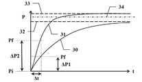
도 2는 시간의 함수로서의 압력 변화 및 비등 탐지 원리의 도시도;
도 3은 비등의 탐지의 흐름도;
도 4는 압력/온도 다이어그램에서의 비등의 정의의 도시도;
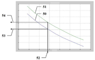
도 5는 압력의 함수로서의 비등점 온도를 나타내는 그래프; 및
도 6은 비등의 탐지에 따른 방법의 흐름도.BRIEF DESCRIPTION OF THE DRAWINGS Figure 1 is a general layout of a tank assembly in context;
2 is an illustration of the principle of pressure change and boiling detection as a function of time;
3 is a flow chart of detection of boiling;
4 is an illustration of the definition of boiling in a pressure / temperature diagram;
5 is a graph showing the boiling point temperature as a function of pressure; And
6 is a flow chart of a method according to the detection of boiling.
도 1은 본 발명에 따른 방법에 의해 압력 제어될 수 있는 타입의 탱크 조립체(1)를 도시한다. 이러한 탱크 조립체(1)는 탱크(2), 필터 또는 캐니스터(3), 파이프(4) 및 차단 밸브(5)를 포함한다. 탱크(2)는 액체(6)를 수용하고 함유할 수 있다. 탱크(2)는 액체 및 가스에 대해 밀봉된다. 액체(6)는 휘발성 액체일 수 있다. 따라서, 필터(3)는 액체(6)로부터 나오는 증기를 포집할 수 있다. 파이프(4)는 탱크(2)를 필터(3)에 밀봉된 방식으로 연결하여 액체 및 가스 모두를 밀봉하는 방식으로 배치된다. 파이프(4)는 유리하게는 액체(6)에 연결되는 것을 피하지만, 바람직하게는 증기에 연결되도록 하기 위해 최상부 근처의 탱크(2)로 태핑한다(tap). 차단 밸브(5)는 파이프(4)를 선택적으로 차단하도록 파이프에 걸쳐 배치된다. 따라서, 차단 밸브(5)는 유리하게는 파이프(4)가 탱크(2)와 필터(3) 사이의 임의의 전달을 방지하도록 차단되는 폐쇄된 위치, 또는 파이프(4)가 흐름을 허용하고, 탱크(2)로부터 필터(3)로 또는 그 반대로 전달을 허용하는 개방 위치로 이동시키도록 전기 제어 신호에 의해 제어될 수 있다.Figure 1 shows a
탱크(2)는 탱크(2)가 액체(6)로 충전되도록 허용하기 위해 선택적으로 개폐될 수 있는 충전 플랩(9)을 더 포함할 수 있다.The
하나의 사용 시나리오에서, 탱크 조립체(1)는 자동차 내에 배치되고, 액체(6)는 휘발성 연료이다.In one usage scenario, the
탱크(2)는 예를 들어 연료의 경우에 액체(6)가 엔진(13)과 같이 소비자에게 보내기 위해 인출되도록 허용하는 액체(6)를 인출하기 위한 적어도 하나의 출구 및 파이프(도시되지 않음)를 더 포함할 수 있다.The
탱크(2)에는 대안적으로 액체(6)를 인출하기 위한 펌프(10)가 장착될 수 있다.The
탱크 조립체(1)는 심지어 탱크(2) 내부에 압력을 측정할 수 있는 압력 센서(7)를 탱크(2) 상에 유리하게 배치할 수 있다. 탱크 조립체(1)는 심지어 탱크(2) 내부에 온도를 측정할 수 있는 온도 센서(8)를 탱크(2) 상에 유리하게 배치할 수 있다.The
전자식으로 인터페이스 가능한 다양한 구성 요소(밸브(5, 12), 센서(7,8) 등)는 엔진 제어 유닛(15)(또는 ECU)과 같은 적어도 하나의 컴퓨터(15)와 유익하게 인터페이스된다. 컴퓨터(15)와 구성 요소(5, 7, 8, 12) 사이의 전기 인터페이스는 점선으로 표시된다.The various electronically interfaced components (
필터(3)는 파이프(4)에 연결시키는 제1 연결부를 포함한다. 그것은 또한 에어 벤트(air vent)(14)에 연결하는 제2 연결부를 포함한다.The filter (3) includes a first connection part for connecting to the pipe (4). It also includes a second connection connecting to an
액체(6)에서 나오는 증기가 예를 들어 오염 물질이기 때문에 대기로 배출되는 것은 바람직하지 못하다. 따라서, 필터(3)는 이러한 증기를 포집하는 기능을 갖는다.It is undesirable for the vapor from the
탱크(2) 내의 저압 또는 진공 압력, 즉 대기압 이하의 압력은 차단 밸브(5)를 개방함으로써 증가될 수 있다. 그런 다음, 예를 들어, 필터(3)의 에어 벤트을 통해 유입되는 공기는 탱크(2)로 유입될 수 있다.The low pressure or the vacuum pressure in the
마찬가지로, 탱크(2) 내의 고압 또는 초과 압력, 즉 대기압보다 높은 압력은 차단 밸브(5)를 개방함으로써 감소될 수 있다. 그런 다음, 액체(6)에서 나오는 증기가 잠재적으로 가득찬 공기는 탱크(2)를 떠나 필터(3)를 향한다. 증기가 필터(3)에 의해 포집되는 동안 공기는 에어 벤트(14)를 통해 빠져 나간다.Likewise, the high or excess pressure in the
필터(3)는 여과 재료, 예를 들어 활성탄을 함유한다. 이러한 여과 재료가 점진적으로 포집된 증기로 가득차게 될 때, 필터(3)의 용량은 감소한다.The
필터(3)의 용량은 재생될 수 있다. 이를 위해, 필터(3)와 증기의 소비자(13) 사이에는 다른 파이프(11)가 있으며, 따라서 필터(3)가 퍼지(purge)되도록 허용한다. 이것은 ("캐니스터 퍼지 솔레노이드(canister purge solenoid)" 또는 CPS로도 알려진 캐니스터 퍼지 밸브와 같은) 퍼지 밸브(12)에 의해 제어될 수 있다. 연료의 경우에, 소비자는 예를 들어 유리하게는 증기를 연소시킬 수 있는 엔진(13)이다.The capacity of the
이러한 환경에서는 어떤 조건 하에 필터(3)의 퍼지/재생을 제어할 수 있다. 또한, 필터의 용량을 추정하는 것이 가능하다. 이것은 출원인 회사의 이름의 다른 특허 출원의 주제(subject)이다.Under such circumstances, the purge / regeneration of the
탱크(2) 내의 압력을 제어하기 위한 관점에서, 액체(6)의 비등을 탐지할 수 있는 것이 매우 유리하다. 이것은 비등이 증기가 배출되는 조건과, 압력이 변화하는 속도를 크게 변경하기 때문이다.From the viewpoint of controlling the pressure in the
평균 온도 및 압력 조건 하에서, 액체(6)는 주로 액상인 바디(body)이다.Under average temperature and pressure conditions, the
비등이 없는 경우, 상기 바디의 기상이 또한 존재할 수 있다. 액체(6)는 2개의 상(phase) 사이의 계면, 즉 액체(6)의 표면에서 증발될 수 있다. 이 경우에 증발 현상은 본질적으로 표면 현상이고, 압력의 적당한 변화를 초래한다. 비등이 없는 한, 분압 또는 포화 증기압은 탱크(2) 내의 압력 이하로 유지된다.In the absence of boiling, the vapor of the body may also be present. The
분압이 정의에 의해 탱크(2) 내의 압력과 동일해질 때까지 증가할 때, 비등점이 도달된다. 이 단계에서, 분압은 액체를 치환시킬 수 있고, 증기는 버블(bubble) 형태로 액체의 체적 전체에 걸쳐 형성된다. 이전에는 표면 현상이었던 증발 현상은 체적 현상(volumetric phenomenon)이 된다. 이것은 압력의 급격한 증가와 함께 증기의 생성 속도의 갑작스러운 증가를 초래한다.When the partial pressure increases by definition to be equal to the pressure in the
따라서, 탱크(2) 내의 압력의 제어와 관련하여 액체(6)의 비등을 탐지할 수 있는 것이 매우 유리하다.Therefore, it is very advantageous to be able to detect the boiling of the liquid 6 in relation to the control of the pressure in the
비등점의 정의와, 특히 도 2에 의해 도시된 바와 같이 비등이 압력의 변화에 미치는 결과에 따라, 비등의 탐지가 수행될 수 있다. 도 2는 횡좌표 축상의 시간(t)의 함수로서 종좌표 축상의 압력(P)을 나타내는 다이어그램을 도시한다. 이러한 다이어그램은 비등의 부재에 대응하는 제1 곡선(30) 및 비등의 존재에 대응하는 제2 곡선(31)을 도시한다. 이것은 밀봉된 탱크(2)에 의해 형성된 바와 같은 일정한 체적 내에 있다.Depending on the definition of the boiling point, and in particular the result of the boiling on the change in pressure as shown by Figure 2, the detection of boiling can be carried out. Fig. 2 shows a diagram showing the pressure P on the ordinate axis as a function of time t on the abscissa axis. This diagram shows a
곡선(30)으로부터, 분압은 탱크(2) 내부의 압력(34)의 값보다 낮게 설정되는 점근적 평형 값(asymptotic equilibrium value)(32)까지 천천히 증가한다는 것을 알 수 있다.From the
한편, 곡선(31)에 의하면, 분압은 급격히 상승한다. 그것은 잠재적으로 탱크(2) 내부의 압력(34)의 값을 초과하는 점근적 평형 값(33)에 도달할 수 있다.On the other hand, according to the
이러한 관찰에 기초하여, 분압이 변화하는 속도를 관찰함으로써 비등 상황을 탐지하는 것이 가능하다. 분압은 탱크(2) 내부의 "전체(total)" 압력에 기여하며, 이러한 두 파라미터는 유사한 변화를 나타낸다. 탱크(2) 내부의 "전체" 압력은 예를 들어 탱크(2) 상에 배치된 압력 센서(7)에 의해 측정될 수 있다.Based on this observation, it is possible to detect the boiling situation by observing the rate at which the partial pressure changes. The partial pressure contributes to the "total" pressure inside the
비등의 탐지는 압력의 기울기 또는 시간 기반 도함수(d)를 임계값(S)과 비교함으로써 수행된다. 시간 기반 도함수(d)가 임계값(S)을 이상이면, 비등은 탐지된다. 한편, 시간 기반 도함수(d)가 임계값(S)을 이하이면, 비등은 존재하지 않는다.The detection of boiling is performed by comparing the slope of the pressure or the time-based derivative d with the threshold value S. If the time-based derivative d exceeds the threshold S, the boiling is detected. On the other hand, if the time-based derivative d is less than or equal to the threshold value S, boiling does not exist.
임계값(S)은 경험적으로 결정되는 상수이다. 일 실시예에 따르면, 가변적 실험 조건(상이한 초기 온도, 액체 교반(liquid agitated) 또는 비교반(nonagitated), 다양한 타입의 액체(가변적 RVP) 등) 하에 있지만 항상 비등의 부재의 제1 샘플 세트, 및 가변적 실험 조건 하에 있지만 이때에는 비등의 존재의 제2 샘플 세트에 대해 온도의 변화를 적용하여 압력의 시간 기반 도함수(d)가 측정된다. 임계값(S)은 두 샘플 세트를 분리하기 위해 선택된다.The threshold value S is an empirically determined constant. According to one embodiment, a first set of samples, always under a variable experimental condition (different initial temperature, liquid agitated or nonagitated, various types of liquids (variable RVP), etc.) but always boiling, and Under time varying experimental conditions, the time-based derivative (d) of the pressure is measured by applying a change in temperature to the second set of samples in the presence of boiling. The threshold value S is selected to separate the two sample sets.
압력의 시간 기반 도함수 d = dP/dt는 변화율 ΔP/Δt를 계산하여 추정된다. 원리는 기간 Δt 동안 차단 밸브(5)를 개방하고, 압력의 대응하는 변화(ΔP, ΔP1, ΔP2)를 측정하는 것이다.The time-based derivative of pressure d = dP / dt is estimated by calculating the rate of change [Delta] P / [Delta] t. The principle is to open the shut-off
이를 수행하기 위해, 도 3의 흐름도를 참조하여 설명되는 다음의 단계를 수행함으로써 비등 탐지가 달성될 수 있다. 제1 단계(40) 동안, 탱크(2)의 초기 압력(Pi)이 측정된 후, 차단 밸브(5)가 개방된다. 차단 밸브(5)는 주어진 개방 기간(Δt) 동안 개방 상태로 유지된다. 이러한 개방 기간(Δt)의 끝에서, 제2 단계(41) 동안, 차단 밸브(5)가 폐쇄되고, 그 후 탱크(2) 내의 최종 압력(Pf)이 측정된다. 제3 단계(42)는 최종 압력(Pf)과 초기 압력(Pi) 사이의 차이(Pf-Pi)와 동일한 압력 변화(ΔP, ΔP1, ΔP2)를 개방 기간(Δt), 즉 d = dP/dt![]()
![]()
개방 기간(Δt)은 압력 변화(ΔP, ΔP1, ΔP2)가 상당할 만큼 충분히 길어야 하지만, 동시에 가능한 짧아야 한다. 실제로, 1초와 10초 사이의 개방 기간(Δt)은 만족스럽다. 2초의 개방 기간(Δt)은 양호한 절충안(compromise)을 구성한다.The open period DELTA t should be long enough so that the pressure changes DELTA P, DELTA P1 and DELTA P2 are comparable, but at the same time as short as possible. In fact, the open period DELTA t between 1 second and 10 seconds is satisfactory. The open period DELTA t of 2 seconds constitutes a good compromise.
비등이 탐지되면, 비등이 발생하고 있음을 나타내는 경고가 유리하게 송신된다. 제1 목적지(destination)는 오퍼레이터일 수 있다. 따라서, 차량에 적용하는 경우, 예를 들어 계기 패널상의 표시기에 의해 운전자의 주의를 위해 경고가 유리하게 보내진다. 대안 또는 부가적으로서 다른 목적지는 적어도 하나의 컴퓨터일 수 있다. 따라서, 차량에 적용하는 경우에, ECU(15)와 같은 컴퓨터는 유리하게 경고된다.If boiling is detected, a warning is sent advantageously indicating that boiling has occurred. The first destination may be an operator. Thus, when applied to a vehicle, a warning is advantageously sent by the indicator on the instrument panel, for example, to the driver's attention. Alternatively or additionally, the other destination may be at least one computer. Therefore, when applied to a vehicle, a computer such as the
액체/연료(6) 내의 버블의 존재 때문에 비등 상태는 시동/재시동을 방지하거나 엔진(13)의 정확한 동작을 방해할 수 있다. 이것은 비등 상태에 대한 지식이 ECU(15)에 사용되는 이유이다.Due to the presence of bubbles in the liquid /
도 6의 흐름도에 의해 도시된 바와 같이, 비등 조건이 탐지될 때 차단 밸브(5)가 개방된다는 것을 입증하면, 이러한 밸브는 폐쇄될 필요가 있다. 일관되게, 차단 밸브(5)가 폐쇄되면, 가능한 모든 단계는 폐쇄 상태를 유지하도록 취해질 필요가 있다. 이것은 폐쇄되거나 폐쇄 상태를 유지하는 단계(45)에 의해 예시된다.As shown by the flow chart in Fig. 6, if the boil-off condition is detected and the shut-off
특히, 차단 밸브(5)의 폐쇄된 위치는 후술하는 바와 같이 비등의 경우에 효과적인 시정 조치(corrective measure)인 것으로 입증할 수 있다.In particular, the closed position of the shut-off
도 4는 제1 액체에 대한 비등점의 제1 궤적(locus)(20)을 도시하는(가로축 상의) 온도에 대한(세로축 상의) 압력의 다이어그램을 도시한다. 액체는 압력/온도 동작점이 곡선(20) 아래에 위치될 경우에 비등한다. 액체는 압력/온도 동작점이 곡선(20) 위에 위치되는 경우에는 비등하지 않는다. 제2 궤적(21)은 제2 액체와 유사하며, 제2 액체는 제1 액체보다(더 높은 비등 온도에 도달할 수 있는) 휘발성이 아니다. 표시로서, 궤적(20)은 "겨울" 연료에 상응할 수 있지만, 궤적(21)은 "여름" 연료에 상응할 수 있다. 저압 값(22) 및 고압 값(23)은 또한 특징을 이루게 되었다. 저압 값(22)은 예를 들어 대기압(1000.10-3 atm)이다. 고압 값(23)은 임의의 값일 수 있지만, 탱크(2)가 견딜 수 있는 최대 한계 압력(Pmax)보다 낮은 것으로 추정된다.FIG. 4 shows a diagram of the pressure (on the ordinate) relative to the temperature (on the abscissa) showing the
궤적(20)에 의해 설명된 바와 같은 특성을 갖는 액체(6)를 고려하면, 압력(22)에서, 온도가 온도 값(24)에 도달하거나 초과할 경우, 이러한 액체(6)는 궤적(20) 상에 위치된 동작점(26)을 갖는다. 따라서, 액체(6)는 비등된다. 이것은 상당한 증기의 방출을 초래한다. 차단 밸브(5)가 폐쇄되면, 액체(6)를 함유하는 탱크 내의 압력은 증가한다. 따라서, 동작점은 포인트(28)를 향해 시프트하고, 그렇게 하면 궤적(20) 위로 이동한다: 비등이 중지된다. 다른 해석은 다음과 같을 수 있다. 압력(23)에 대해, 궤적(20)상의 비등점은 액체(6)의 온도(24)보다 높은 온도(25)에 상응하는 포인트(27)이다.Considering the
이것은 (가로축 상의) RVP에 대한 (세로축 상의) 온도의 다이어그램인 도 5의 그래프에서 다시 볼 수 있다. RVP("Reid Vapour Pressure")는 압력에서 균일한 액체(6)의 휘발성을 나타내는 지표이다. RVP가 높을수록 액체의 휘발성이 높아지고 비등 온도는 낮아진다.This can be seen again in the graph of FIG. 5, which is a diagram of the temperature (on the ordinate) relative to the RVP (on the abscissa). RVP ("Reid Vapor Pressure") is an indicator of the volatility of liquid (6) uniformly at pressure. The higher the RVP, the higher the volatility of the liquid and the lower the boiling temperature.
이러한 다이어그램은 제1 압력에 대응하는 제1 곡선(50) 및 제1 압력보다 높은 제2 압력에 대응하는 제2 곡선(51)을 도시한다. 곡선(50, 51)에 대응하는 주어진 압력에서, 액체(6)는 이의 정의점(defining point)(RVP, 온도)이 곡선(50, 51) 위에 있을 경우에 비등하고, 곡선(50, 51) 아래에 있을 경우에는 비등하지 않는다. 이러한 그래프는 다음과 같이 판독될 수 있다. 주어진 휘발성(52)에 의해 정의된 액체(6)에 대해, 가로축(이 경우, 690 hPa)에서 판독하면, 수직 직선은 상기 제1 압력에서 이러한 액체(6)의 비등점(여기서는 51℃)을 특징으로 하는 세로축 포인트(53)에서 제1 압력에 대응하는 제1 곡선(50)과 교차한다. 이러한 동일한 액체(6)에 대해, 수직 직선은 상기 제2 압력에서 이러한 액체(6)의 비등점(여기서는 56℃)을 특징으로 하는 세로축 포인트(54)에서 제2 압력에 대응하는 제2 곡선(51)과 교차한다. 비등점(53, 54)이 비등에 의해 생성된 압력의 증가로 증가하기 때문에, 액체(6)의 유효 온도는 비등점 아래로 떨어질 수 있으며, 따라서 액체(6)는 비등을 중지한다.This diagram shows a
따라서, 일정한 체적에서의 제한(confinement)은, 차단 밸브(5)의 폐쇄 또는 폐쇄 상태의 유지를 통해, 유리하게는 비등을 중지시켜 새로운 압력 평형이 형성되도록 허용할 수 있는 것처럼 보일 것이다.Thus, confinement at a constant volume will appear to be able to allow the boiling to be stopped, advantageously through the maintenance of the closed or closed state of the
비등의 탐지는 유리하게는 차단 밸브(5)의 폐쇄로 이어진다. 그러나, 차단 밸브(5)의 폐쇄로 이어지는 다른 이유가 있다. 필터(3)가 제한된 용량을 갖는다는 사실은 필터(3)가 사용되는 시간을 제어하기 위해 차단 밸브(5)를 폐쇄된 상태로 유지하는 것을 장려하는 한 가지 이유이다. 필터(3)의 충전을 추정하는 방법은 또한 필터(3)에 대한 제어된 환경을 필요로 하며, 따라서 또한 차단 밸브(5)를 폐쇄된 상태로 유지하는 것을 장려한다. 따라서, 일 실시예에 따르면, 차단 밸브(5)는 기본적으로 폐쇄된 상태로 유지된다.The detection of boiling leads advantageously to the closing of the shut-off
도 6의 흐름도에 도시된 바와 같은 압력 제어 방법은 규칙적으로 및 잠재적 비등에 관한 상태와 관계없이 다음의 단계를 수행한다.The pressure control method as shown in the flow chart of Fig. 6 performs the following steps irrespective of the condition about the regular boiling and the potential boiling.
단계(46) 동안, 탱크(2) 내의 압력(P)은 예를 들어 압력 센서(7)를 사용하여 측정된다. 이러한 압력(P)은 단계(47) 동안 탱크(2)의 최소 한계 압력(Pmin) 및 탱크(2)의 최대 한계 압력(Pmax)에 대해 비교된다.During
압력(P)이 탱크(2)의 최소 한계 압력(Pmin) 이하인 경우, 탱크(2)는 진공 압력에 있고 손상될 위험이 있다. 따라서, 단계(48) 동안, 차단 밸브(5)를 개방하는 것이 적절하다. 이것은 예를 들어 필터(3)의 에어 벤트(14)를 통해 예를 들어 공기가 탱크(2)로 들어가도록 허용하여, 잠재적으로 대기압에 가까운 값에 도달할 때까지 압력(P)이 다시 증가하도록 허용한다. 이러한 상황은 시스템으로부터의 발산(emanation)이 반박되지 않는 한 많은 문제를 나타내지 않으며, 따라서 오염의 위험이 없다.If the pressure P is below the minimum critical pressure Pmin of the
압력(P)이 탱크(2)의 최대 한계 압력(Pmax) 이상인 경우, 탱크(2)는 과압 상태에 있고, 손상될 위험이 있다. 따라서, 단계(48) 동안 차단 밸브(5)를 개방하는 것이 적절하다. 이것은 아마 액체(6)로부터 발산하는 증기로 가득찬 공기가 탱크(2)를 떠나도록 허용한다. 이것은 공기가 에어 벤트(14)를 통해 빠져 나가도록 허용하고, 그 용량의 한계 내에서 증기를 포집하는 필터(3)를 통해 행해진다. 이것은 가능하다면 대기압에 가까운 값이 도달될 때까지 압력(P)이 떨어지도록 허용한다.When the pressure P is equal to or higher than the maximum limit pressure Pmax of the
이러한 상황은 과압이 필터(3)의 용량을 초과하여 유지될 경우에 문제가 될 수 있다. 여기서, 방법은 증기 오염의 위험보다 압력(P)을 낮추는 안전성을 선호한다. 탱크(2)에 대한 손상은 파열로 이어질 수 있으며, 이는 더 많은 결과를 생성시키고, 액체(6)를 포함하는 누출을 유발시키며, 이는 오염면에서 훨씬 더 해롭다. 이러한 위험을 제한하기 위해, 필터(3)가 가능한 빨리 퍼지되도록 보장하기 위해 그것은 압력(P)이 최대 한계 압력(Pmax) 이하인 한 사전에 적절하다.This situation may be a problem when the overpressure is kept over the capacity of the
압력(P)이 최소 한계 압력(Pmin)과 최대 한계 압력(Pmax) 사이에 포함되는 경우, 방법은 통상적으로 압력(P)을 측정하는 단계(46)로 루프백(loop back)될 수 있다.If the pressure P is included between the minimum limit pressure Pmin and the maximum limit pressure Pmax, the method can typically be looped back to step 46 of measuring the pressure P.
단계(46-48)에 의해 수행되는 최소 한계 압력(Pmin) 및 최대 한계 압력(Pmax)과 관련하여 탱크(2)의 압력을 모니터링하는 것은 유리하게는 탱크(2)의 완전성(integrity)을 보장하기 위해 규칙적으로 수행된다. 그러나, 이러한 모니터링은 비등 상황이 압력의 크고 빠른 증가를 생성하며, 따라서 최대 한계 압력(Pmax)에 도달하는 상당한 위험을 초래하기 때문에 비등(44)의 탐지에 따른 더 큰 이점이 있다.Monitoring the pressure of the
양호한 응답성을 보장하기 위해, 비등의 탐지는 제1 실시예에 따라 규칙적으로 수행될 수 있다.In order to ensure good responsiveness, the detection of boiling can be performed regularly according to the first embodiment.
대안적으로, 차단 밸브(5)를 과도하게 개방하지 않기 위해, 비등의 탐지는 이벤트의 출현 시에 수행될 수 있다. 비등의 혐의(suspicion)를 정당화할 수 있는 제1 이벤트는 예를 들어 압력의 규칙적인 모니터링에 의해 탐지되는 탱크 2의 압력의 상당한 변화이다.Alternatively, in order not to open the
다른 타입의 이벤트는 플랩(9)을 충전하는 탱크(2)를 개방하는 요구이다. 탱크(2)는 밀봉되고, 탱크(2) 외부의 대기압과 상이한 압력을 받을 수 있기 때문에, 충전 플랩(9)은 잠겨질 필요가 있다. 따라서, 오퍼레이터가 탱크(2)를 충전하기를 원할 때, 오퍼레이터는 그렇게 하기 위해 적절한 요청을 한다. 이러한 요청은 개방하는 요구의 형태로 개방을 인가하거나 인가하지 않는 시스템으로 송신된다. 개방이 인가되면, 잠금 해제 명령이 실제로 플랩(9)에 보내지고, 그 후 개방될 수 있다. 이러한 처리는 시스템이 개방을 인가하거나 인가하지 않기 전에 탱크(2) 상에서 어떤 체크 또는 동작을 수행하도록 허용한다. 사전 체크 중 하나는 통상적으로 비등이 뒤따르게 되는 행동을 상당히 변경시킬 수 있는 한 비등을 탐지하는 것이다. 플랩(9)의 개방을 작동하기 전의 하나의 동작은 전형적으로 외부의 압력, 즉 통상적으로 대기압에 가능한 가까운 압력에서 탱크의 내부를 배치하려고 시도하는 것이다.Another type of event is a request to open the
개방하는 요구를 처리하는 원칙은 개방하는 요청이 대부분의 경우에 긍정적으로 잠금 해제가 뒤따라야 한다는 것이다.The principle of handling an open request is that an open request should in most cases be unlocked positively.
그러나, 시스템은 다양한 체크 및/또는 동작을 사전에 수행하기 위해 실제 개방을 지연시킬 수 있다.However, the system may delay the actual opening to perform various checks and / or operations in advance.
시스템은 전형적으로 개방 전에 탱크(2)의 내부와 외부 사이의 압력의 균형을 맞추려고 시도할 것이다. 시스템은 유리하게는 비등 탐지를 수행할 것이다. 이러한 비등 탐지가 긍정적이면, 압력 사이의 평형이 달성하기 까다로울 수 있다.The system will typically attempt to balance the pressure between the interior and the exterior of the
그 후, 시스템은 오퍼레이터에게 비등 상태 및/또는 차압 상태를 경고할 수 있다. 고온의 액체가 비등 상태 및/또는 과압 상태 때문에 플랩(9)으로부터 배출될 위험이 있다.The system can then alert the operator to boiling and / or differential pressure conditions. There is a risk that the hot liquid is discharged from the
시스템은 통지받은 오퍼레이터로부터 개방하는 요청의 확인을 요구할 수도 있다.The system may request confirmation of the request to open from the notified operator.
Claims (9)
상기 탱크(2)에 담긴 상기 액체의 비등을 탐지하는 단계를 포함하되, 상기 비등을 탐지하는 단계는,
Detecting boiling of the liquid contained in the tank (2), wherein the step of detecting boiling comprises:
Applications Claiming Priority (3)
| Application Number | Priority Date | Filing Date | Title |
|---|---|---|---|
| FR1553257 | 2015-04-14 | ||
| FR1553257A FR3035213B1 (en) | 2015-04-14 | 2015-04-14 | PRESSURE CONTROL METHOD INCLUDING BOILING DETECTION |
| PCT/EP2016/000601 WO2016165821A1 (en) | 2015-04-14 | 2016-04-12 | Method for monitoring pressure including boil detection |
Publications (2)
| Publication Number | Publication Date |
|---|---|
| KR20170137132A true KR20170137132A (en) | 2017-12-12 |
| KR102573430B1 KR102573430B1 (en) | 2023-08-31 |
Family
ID=53366146
Family Applications (1)
| Application Number | Title | Priority Date | Filing Date |
|---|---|---|---|
| KR1020177031812A KR102573430B1 (en) | 2015-04-14 | 2016-04-12 | Pressure monitoring method including boiling detection |
Country Status (5)
| Country | Link |
|---|---|
| US (1) | US10416688B2 (en) |
| KR (1) | KR102573430B1 (en) |
| CN (1) | CN107438531B (en) |
| FR (1) | FR3035213B1 (en) |
| WO (1) | WO2016165821A1 (en) |
Families Citing this family (2)
| Publication number | Priority date | Publication date | Assignee | Title |
|---|---|---|---|---|
| FR3053398B1 (en) * | 2016-06-30 | 2018-08-10 | Continental Automotive France | METHOD FOR CONTROLLING A PRESSURE MEASUREMENT IN A FUEL TANK |
| EP3498515A1 (en) | 2017-12-18 | 2019-06-19 | Plastic Omnium Advanced Innovation and Research | Method for determining the thermodynamic state of the fuel in a fuel system |
Citations (4)
| Publication number | Priority date | Publication date | Assignee | Title |
|---|---|---|---|---|
| DE19913440A1 (en) * | 1999-03-25 | 2000-10-05 | Bayerische Motoren Werke Ag | Fuel tank ventilation system for motor vehicles has tank constructed for max. operational pressure higher than ambient pressure and closeable ventilation valves |
| KR20080007396A (en) * | 2005-05-04 | 2008-01-18 | 지엠 글로벌 테크놀러지 오퍼레이션스, 인코포레이티드 | Control of induction system hydrocarbon emissions |
| US20110295482A1 (en) * | 2010-05-28 | 2011-12-01 | Ford Global Technologies, Llc | Method and system for fuel vapor control |
| EP2468556A2 (en) * | 2010-12-21 | 2012-06-27 | Audi Ag | Method and device for controlling the pressure inside a fuel tank |
Family Cites Families (5)
| Publication number | Priority date | Publication date | Assignee | Title |
|---|---|---|---|---|
| JPH11223152A (en) * | 1998-02-05 | 1999-08-17 | Mitsubishi Motors Corp | Temperature condition display device for vehicle engine cooling water |
| US8434461B2 (en) * | 2011-04-29 | 2013-05-07 | Ford Global Technologies, Llc | Method and system for fuel vapor control |
| CN104176262B (en) * | 2014-09-15 | 2016-05-04 | 北京航空航天大学 | A kind of aircraft pressurize fuel tank |
| DE102015012656A1 (en) * | 2014-10-22 | 2016-04-28 | Audi Ag | Method for operating a fuel system for a motor vehicle and corresponding fuel system |
| JP6337806B2 (en) * | 2015-03-10 | 2018-06-06 | トヨタ自動車株式会社 | Evaporative fuel processing equipment |
-
2015
- 2015-04-14 FR FR1553257A patent/FR3035213B1/en active Active
-
2016
- 2016-04-12 KR KR1020177031812A patent/KR102573430B1/en active IP Right Grant
- 2016-04-12 WO PCT/EP2016/000601 patent/WO2016165821A1/en active Application Filing
- 2016-04-12 CN CN201680021901.6A patent/CN107438531B/en active Active
- 2016-04-12 US US15/566,615 patent/US10416688B2/en active Active
Patent Citations (4)
| Publication number | Priority date | Publication date | Assignee | Title |
|---|---|---|---|---|
| DE19913440A1 (en) * | 1999-03-25 | 2000-10-05 | Bayerische Motoren Werke Ag | Fuel tank ventilation system for motor vehicles has tank constructed for max. operational pressure higher than ambient pressure and closeable ventilation valves |
| KR20080007396A (en) * | 2005-05-04 | 2008-01-18 | 지엠 글로벌 테크놀러지 오퍼레이션스, 인코포레이티드 | Control of induction system hydrocarbon emissions |
| US20110295482A1 (en) * | 2010-05-28 | 2011-12-01 | Ford Global Technologies, Llc | Method and system for fuel vapor control |
| EP2468556A2 (en) * | 2010-12-21 | 2012-06-27 | Audi Ag | Method and device for controlling the pressure inside a fuel tank |
Also Published As
| Publication number | Publication date |
|---|---|
| KR102573430B1 (en) | 2023-08-31 |
| FR3035213A1 (en) | 2016-10-21 |
| CN107438531B (en) | 2019-11-01 |
| WO2016165821A1 (en) | 2016-10-20 |
| FR3035213B1 (en) | 2018-08-10 |
| US20180088603A1 (en) | 2018-03-29 |
| CN107438531A (en) | 2017-12-05 |
| US10416688B2 (en) | 2019-09-17 |
Similar Documents
| Publication | Publication Date | Title |
|---|---|---|
| US10549628B2 (en) | Fuel system for a motor vehicle | |
| US9982841B2 (en) | Method for filling a tank with liquefied gas | |
| JP6509831B2 (en) | Method and system for depressurizing a fuel storage system for a vehicle | |
| EP2116716B1 (en) | Leak diagnostic apparatus for an evaporative emission control system | |
| EP1981731B1 (en) | Method for recovering vapor during an onboard refueling operation | |
| US20140026992A1 (en) | Fuel tank depressurization with shortened wait time | |
| JP5783392B2 (en) | Fuel tank system | |
| JP6572915B2 (en) | Fuel tank system and control method thereof | |
| EP2993069B1 (en) | Method and system for controlling a filling operation of a vehicular liquid storage system | |
| JP2008518151A (en) | Refueling system and method | |
| KR20170137132A (en) | Pressure monitoring methods including boiling detection | |
| JP5901813B1 (en) | Pressure sensor failure detection device | |
| CN107206891B (en) | Vapor recovery system and vapor control method | |
| US10549629B2 (en) | Method for controlling depressurisation in a motor vehicle fuel tank | |
| US20090107580A1 (en) | Electronic Refueling and Vent Control System with Integrated Control | |
| US11118958B2 (en) | System for determining a filling level in a fuel tank | |
| EP1130248B1 (en) | Fuel system vapor integrity testing with temperature compensation | |
| US11040866B2 (en) | Method for detecting defective gas flow in a purge device vent line | |
| JP6506063B2 (en) | Fuel control system for vehicles | |
| WO2021002160A1 (en) | Evaporated fuel treatment device | |
| JP6252565B2 (en) | Evaporative fuel processing equipment | |
| JP6967490B2 (en) | Occlusion diagnostic device | |
| JP7325317B2 (en) | Diagnosis system for circulatory path blockage | |
| JP7152345B2 (en) | Closed fuel tank system | |
| JP2022178457A (en) | Control device for fuel tank system |
Legal Events
| Date | Code | Title | Description |
|---|---|---|---|
| E902 | Notification of reason for refusal | ||
| E701 | Decision to grant or registration of patent right | ||
| GRNT | Written decision to grant |