KR20170135150A - Welding robot system for working of curved block narrow range and control method thereof - Google Patents
Welding robot system for working of curved block narrow range and control method thereof Download PDFInfo
- Publication number
- KR20170135150A KR20170135150A KR1020160066607A KR20160066607A KR20170135150A KR 20170135150 A KR20170135150 A KR 20170135150A KR 1020160066607 A KR1020160066607 A KR 1020160066607A KR 20160066607 A KR20160066607 A KR 20160066607A KR 20170135150 A KR20170135150 A KR 20170135150A
- Authority
- KR
- South Korea
- Prior art keywords
- welding robot
- welding
- robot
- tilting
- linear
- Prior art date
Links
Images


Classifications
-
- B—PERFORMING OPERATIONS; TRANSPORTING
- B23—MACHINE TOOLS; METAL-WORKING NOT OTHERWISE PROVIDED FOR
- B23K—SOLDERING OR UNSOLDERING; WELDING; CLADDING OR PLATING BY SOLDERING OR WELDING; CUTTING BY APPLYING HEAT LOCALLY, e.g. FLAME CUTTING; WORKING BY LASER BEAM
- B23K31/00—Processes relevant to this subclass, specially adapted for particular articles or purposes, but not covered by only one of the preceding main groups
- B23K31/02—Processes relevant to this subclass, specially adapted for particular articles or purposes, but not covered by only one of the preceding main groups relating to soldering or welding
-
- B—PERFORMING OPERATIONS; TRANSPORTING
- B23—MACHINE TOOLS; METAL-WORKING NOT OTHERWISE PROVIDED FOR
- B23K—SOLDERING OR UNSOLDERING; WELDING; CLADDING OR PLATING BY SOLDERING OR WELDING; CUTTING BY APPLYING HEAT LOCALLY, e.g. FLAME CUTTING; WORKING BY LASER BEAM
- B23K11/00—Resistance welding; Severing by resistance heating
- B23K11/10—Spot welding; Stitch welding
- B23K11/11—Spot welding
-
- B—PERFORMING OPERATIONS; TRANSPORTING
- B23—MACHINE TOOLS; METAL-WORKING NOT OTHERWISE PROVIDED FOR
- B23K—SOLDERING OR UNSOLDERING; WELDING; CLADDING OR PLATING BY SOLDERING OR WELDING; CUTTING BY APPLYING HEAT LOCALLY, e.g. FLAME CUTTING; WORKING BY LASER BEAM
- B23K37/00—Auxiliary devices or processes, not specially adapted to a procedure covered by only one of the preceding main groups
- B23K37/02—Carriages for supporting the welding or cutting element
- B23K37/0211—Carriages for supporting the welding or cutting element travelling on a guide member, e.g. rail, track
-
- B—PERFORMING OPERATIONS; TRANSPORTING
- B23—MACHINE TOOLS; METAL-WORKING NOT OTHERWISE PROVIDED FOR
- B23K—SOLDERING OR UNSOLDERING; WELDING; CLADDING OR PLATING BY SOLDERING OR WELDING; CUTTING BY APPLYING HEAT LOCALLY, e.g. FLAME CUTTING; WORKING BY LASER BEAM
- B23K37/00—Auxiliary devices or processes, not specially adapted to a procedure covered by only one of the preceding main groups
- B23K37/02—Carriages for supporting the welding or cutting element
- B23K37/0282—Carriages forming part of a welding unit
-
- B—PERFORMING OPERATIONS; TRANSPORTING
- B23—MACHINE TOOLS; METAL-WORKING NOT OTHERWISE PROVIDED FOR
- B23K—SOLDERING OR UNSOLDERING; WELDING; CLADDING OR PLATING BY SOLDERING OR WELDING; CUTTING BY APPLYING HEAT LOCALLY, e.g. FLAME CUTTING; WORKING BY LASER BEAM
- B23K9/00—Arc welding or cutting
- B23K9/007—Spot arc welding
-
- B—PERFORMING OPERATIONS; TRANSPORTING
- B25—HAND TOOLS; PORTABLE POWER-DRIVEN TOOLS; MANIPULATORS
- B25J—MANIPULATORS; CHAMBERS PROVIDED WITH MANIPULATION DEVICES
- B25J11/00—Manipulators not otherwise provided for
- B25J11/005—Manipulators for mechanical processing tasks
-
- B—PERFORMING OPERATIONS; TRANSPORTING
- B25—HAND TOOLS; PORTABLE POWER-DRIVEN TOOLS; MANIPULATORS
- B25J—MANIPULATORS; CHAMBERS PROVIDED WITH MANIPULATION DEVICES
- B25J9/00—Programme-controlled manipulators
- B25J9/02—Programme-controlled manipulators characterised by movement of the arms, e.g. cartesian coordinate type
- B25J9/04—Programme-controlled manipulators characterised by movement of the arms, e.g. cartesian coordinate type by rotating at least one arm, excluding the head movement itself, e.g. cylindrical coordinate type or polar coordinate type
- B25J9/041—Cylindrical coordinate type
- B25J9/042—Cylindrical coordinate type comprising an articulated arm
Landscapes
- Engineering & Computer Science (AREA)
- Mechanical Engineering (AREA)
- Physics & Mathematics (AREA)
- Robotics (AREA)
- Optics & Photonics (AREA)
- Plasma & Fusion (AREA)
- Manipulator (AREA)
- Numerical Control (AREA)
Abstract
Description
본 발명은 곡블록 협소구간 작업이 가능한 용접로봇 시스템 및 그 제어방법에 관한 것으로, 특히 틸팅장치와 부가 자유도를 가진 직선유닛을 이용하여 용접 로봇의 작업 영역을 확장하여, 곡블록 협소구간의 작업이 원활히 이루어지도록 한 곡블록 협소구간 작업이 가능한 용접로봇 시스템 및 그 제어방법에 관한 것이다.[0001] The present invention relates to a welding robot system capable of narrow block section work and a control method thereof, and in particular, by extending a working area of a welding robot using a tilting apparatus and a linear unit having additional degrees of freedom, The present invention relates to a welding robot system and a control method thereof,
메카트로닉스(mechatronics) 관련 기술이 급속도로 발달함에 따라 산업현장에서 실로 다양한 형태의 로봇(robot)이 등장하였다. 예를 들어, 자동차 생산 현장이나 선박 건조 현장에서 용접라인에 일렬로 배치된 다수의 스폿용접용 로봇(다관절 용접 로봇)을 들 수 있다.As mechatronics-related technology rapidly developed, various types of robots appeared in the industrial field. For example, there are a number of spot welding robots (multi-joint welding robots) arranged in a line on a welding line at an automobile production site or a ship drying site.
특히, LNG선과 같이 곡블록이 많은 선박의 건조 시 용접로봇을 많이 활용한다. 곡블록 부위는 작업공간이 매우 협소하며, 용접부위도 기울어져 있어 사람이 작업하기가 매우 곤란하다.In particular, welding robots are often used for drying vessels with many tongue blocks, such as LNG carriers. The curved block area is very narrow in the work space and the welding part is also inclined, making it very difficult for a person to work.
따라서 이 경우 용접로봇을 이용하여 작업을 하는 경우가 많다. In this case, welding robots are often used.
용접로봇을 이용하여 곡블록 부위를 용접할 때, 특정 위치에 로봇 베이스를 고정하고 작업을 진행한다.When welding a tune block using a welding robot, fix the robot base at a specific position and proceed with the work.
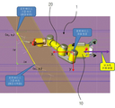
도 1 및 도 2는 종래 곡블록 작업을 하는 용접로봇(1)의 작업 상태도로서, 곡블록 작업 시 로봇 베이스(10)를 특정 위치에 고정하고, 다관절로 이루어진 팔(20)을 관절별로 피치 및 롤 방향으로 회전시키면서 용접 작업을 진행한다.FIG. 1 and FIG. 2 are working state diagrams of a
곡블록 작업을 수행하는 용접로봇의 제어를 위한 종래 기술이 하기의 <특허문헌 1> 에 개시되어 있다.A conventional technique for controlling a welding robot performing a tune block operation is disclosed in
<특허문헌 1> 에 개시된 종래기술은 거더, 트롤리, 원통형 업다운 붐, 상기 원통형 업다운 붐의 하부에 축결합된 선회 부재, 상기 선회 부재에 회전력을 제공하도록 원통형 업다운 붐의 일측 원주면에 장치된 모터, 선회축 장치의 회전 부재 하부면 일 지점에 결합된 로봇 부착부를 포함한다.The prior art disclosed in
이러한 구성을 통해, 곡블록 용접장치를 이루는 업다운 붐의 끝단에 장치된 용접로봇이 선회되도록 구성하여 갠트리 이동시 트란스 설치에 따른 간섭 없이 원활히 빠르게 이동 후 목적지점에서 용접로봇을 회전시켜 더 접근된 위치에서 용접을 수행하도록 한다.With this configuration, the welding robot installed at the end of the up-down boom constituting the curved block welding apparatus is configured to be turned, so that the gantry can be smoothly and quickly moved without interference due to the installation of the gantry, The welding is performed.
그러나 상기와 같은 종래기술은 용접로봇이 작업영역을 확장하기 위해서 부가적으로 트롤리와 같은 부가 장비를 이용하므로, 곡블록 협소 구간을 작업할 경우, 트롤리의 설치가 복잡하거나 트롤리 설치가 불가능하여 곡블록 협소구간의 작업 시 용접작업이 이루어지지 않는 영역이 발생하는 단점이 있다.However, in the conventional art as described above, since the welding robot uses additional equipment such as a trolley in order to expand the work area, it is difficult to install the trolley, There is a disadvantage that an area where the welding operation is not performed occurs in a narrow range of work.
또한, 일반적인 용접로봇을 이용하여 곡블록 협소 구간의 작업 시, 도 1 및 도 2에 도시한 바와 같이, 작업공간이 협소하고 용접부위가 기울어진 작업대상물 특성상 용접로봇의 작업영역이 부족하여, 수평 용접이 이루어지지 않거나 수직 일부 용접만 이루어지는 문제점이 발생하였다.As shown in Figs. 1 and 2, when the workpiece is narrow in the curved block using a general welding robot, the working space of the welding robot is insufficient due to the nature of the workpiece in which the work space is narrow and the welding portion is inclined, There arises a problem that welding is not performed or only vertical partial welding is performed.
이렇게 용접이 이루어지지 않는 문제를 해소하기 위해서, 로봇 링크를 연장하거나 작업영역이 부족한 부분에 직선유닛의 부가 축을 이용하는 방법도 제안되었다. 그러나 로봇 링크를 연장하는 방식은 모터 용량을 증설하는 등과 같이 용접로봇 설계를 다시 해야 하는 문제점을 유발하며, 부가 축을 이용하는 방식은 자유도가 증가하는 상황이 되어 동시동작을 하는 용접로봇의 경우 운동학을 구현하는 데 어려움이 발생하였다.In order to solve the problem that the welding is not performed, a method of extending the robot link or using the additional axis of the linear unit at the portion where the work area is insufficient has been proposed. However, the method of extending the robot link causes a problem that the design of the welding robot should be re-designed such as the increase of the motor capacity, and the method using the additional axis becomes a situation where the degree of freedom is increased. Difficulties were encountered.
따라서 본 발명은 상기와 같은 종래기술에서 발생하는 제반 문제점을 해결하기 위해서 제안된 것으로서, 틸팅장치와 부가 자유도를 가진 직선유닛을 이용하여 용접 로봇의 작업 영역을 확장하여, 곡블록 협소구간의 작업이 원활히 이루어지도록 한 곡블록 협소구간 작업이 가능한 용접로봇 시스템 및 그 제어방법에 관한 것이다.SUMMARY OF THE INVENTION Accordingly, the present invention has been made to solve the above-mentioned problems occurring in the prior art, and it is an object of the present invention to expand the work area of a welding robot using a tilting device and a linear unit having additional degrees of freedom, The present invention relates to a welding robot system and a control method thereof,
상기한 바와 같은 목적을 달성하기 위하여, 본 발명에 따른 곡블록 협소구간 작업이 가능한 용접로봇 시스템의 제1 실시 예는 로봇 베이스와 다관절 로봇팔 및 토치를 포함하고, 자유도를 이용하여 곡블록 용접을 수행하는 용접로봇; 상기 용접로봇의 베이스와 결합하며, 상기 용접로봇의 직선 자유도를 부가하여 작업 영역을 확장하는 직선 부가 축을 포함하는 것을 특징으로 한다.In order to achieve the above-mentioned object, a first embodiment of a welding robot system capable of performing a tune block narrow interval operation according to the present invention includes a robot base, a multi-joint robot arm and a torch, A welding robot for performing welding; And a linear portion coupled to the base of the welding robot and extending a work area by adding a linear degree of freedom of the welding robot.
상기에서 직선 부가 축은 상기 용접로봇과 병진운동으로 동시 동작하는 것을 특징으로 한다.Wherein the linear shafts are simultaneously operated by translational motion with the welding robot.
또한, 본 발명에 따른 곡블록 협소구간 작업이 가능한 용접로봇 시스템의 제2 실시 예는 로봇 베이스와 다관절 로봇팔 및 토치를 포함하고, 자유도를 이용하여 곡블록 용접을 수행하는 용접로봇; 상기 용접로봇의 베이스와 결합하며, 곡블록 기울기에 따라 상기 용접로봇을 틸팅시키는 틸팅수단; 상기 틸팅수단과 결합하며, 상기 용접로봇에 직선 자유도를 부가하여 작업 영역을 확장하는 직선 부가 축을 포함하는 것을 특징으로 한다.A welding robot system according to a second embodiment of the present invention includes a robot base, a multi-joint robot arm, and a torch. Tilting means coupled to the base of the welding robot and tilting the welding robot according to a tilting block tilt; And a linear portion coupled to the tilting means and extending a work area by adding a linear degree of freedom to the welding robot.
상기에서 직선 부가 축은 상기 용접로봇과 병진운동으로 동시 동작하는 것을 특징으로 한다.Wherein the linear shafts are simultaneously operated by translational motion with the welding robot.
또한, 본 발명에 따른 곡블록 협소구간 작업이 가능한 용접로봇 시스템의 제어방법은 (a) 작업대상물에 용접로봇을 위치시키는 단계; (b) 틸팅수단으로 상기 용접로봇의 각도를 설정하는 단계; (c) 작업 시작 명령이 입력되면, 목표점 위치좌표를 획득하는 단계; (d) 현재 위치를 계산하는 단계; (e) 상기 목표점과 현재 위치와의 거리를 계산하는 단계; (f) 상기 (e)단계에서 계산한 거리 값을 용접로봇 보간과 직선 구간 보간 영역으로 분할하는 단계; (g) 상기 (f)단계에서 분할한 보간 영역별로 축 이동 값을 보간하는 단계; (h) 상기 (g)단계에서 보간한 축 이동 값을 기초로 용접로봇 및 직선 부가 축을 동작시켜 목표점으로 이동하는 단계를 포함하는 것을 특징으로 한다.According to another aspect of the present invention, there is provided a method of controlling a welding robot system capable of performing a narrow block section of a curved block, comprising the steps of: (a) positioning a welding robot on a workpiece; (b) setting an angle of the welding robot with tilting means; (c) if a task start command is input, acquiring a target point position coordinate; (d) calculating a current position; (e) calculating a distance between the target point and the current position; (f) dividing the distance value calculated in the step (e) into welding robot interpolation and linear region interpolation areas; (g) interpolating an axis shift value for each interpolation area divided in step (f); (h) moving the welding robot and the linear part to the target point by operating the axis based on the axis movement value interpolated in step (g).
상기에서 (d)단계는 툴 끝점의 위치를 현재 위치로 계산하는 것을 특징으로 한다.In the step (d), the position of the tool end point is calculated as the current position.
상기에서 (e)단계는 하기의 수식을 이용하여 목표점과 현재 위치와의 거리(ΔP)를 계산하는 것을 특징으로 한다.In the step (e), the distance? P between the target point and the current position is calculated using the following equation.
![]()
![]()
여기서 P2는 목표점 좌표, P1은 현재 위치 좌표, α는 기울기를 나타낸다.Where P 2 is the target point coordinate, P 1 is the current position coordinate, and α is the slope.
상기에서 (g)단계는 (g1) 로봇 6축을 보간하는 단계; (g2) 직선 부가 축을 보간하는 단계를 포함하는 것을 특징으로 한다.The step (g) comprises the steps of (g1) interpolating the six axes of the robot; (g2) interpolating the axis with the straight line.
상기에서 (h)단계는 용접로봇 및 직선 부가 축을 동기화하여 병진운동으로 동시 동작시키는 것을 특징으로 한다.In the step (h), the welding robot and the linear part synchronously operate the shafts in a translational motion.
본 발명에 따르면 틸팅장치와 부가 자유도를 가진 직선유닛을 이용하여 용접 로봇의 작업 영역을 확장함으로써, 곡블록 협소 구간의 작업을 원활히 수행할 수 있는 장점도 있다.According to the present invention, the work area of the welding robot is expanded by using the tilting device and the linear unit having additional degrees of freedom, so that it is possible to smoothly perform the operation of the narrow block of the tune block.
또한, 본 발명에 따르면 상기와 같은 곡블록 협소 구간의 작업 원활함으로 인해 작업공간이 협소하고 용접부위가 기울어진 작업대상물도 수평 용접이 이루어지지 않거나 수직 일부 용접만 이루어지는 것을 방지할 수 있는 장점이 있다.In addition, according to the present invention, there is an advantage in that the work space in which the work space is narrow and the welding part is inclined due to the smooth operation of the curved block narrow section as described above can be prevented from being horizontally welded or only partially vertically welded .
도 1 및 도 2는 종래 곡블록 작업을 하는 용접로봇의 작업 상태도,
도 3은 본 발명에 따른 곡블록 협소구간 작업이 가능한 용접로봇 시스템의 개략 구성도,
도 4는 도 3의 분해도,
도 5 및 도 6은 본 발명에서 곡블록 협소구간 작업이 가능한 용접로봇 시스템의 작업 상태도,
도 7은 본 발명에 따른 곡블록 협소구간 작업이 가능한 용접로봇 시스템의 제어방법을 보인 흐름도.Fig. 1 and Fig. 2 are diagrams showing a working state of a welding robot performing a conventional tune block operation,
FIG. 3 is a schematic view of a welding robot system capable of work on a narrow block of a tune block according to the present invention;
Figure 4 is an exploded view of Figure 3,
FIG. 5 and FIG. 6 are diagrams showing the operation state of the welding robot system capable of performing the narrow block section of the curved block in the present invention,
FIG. 7 is a flowchart illustrating a control method of a welding robot system capable of performing a narrow block segment operation according to the present invention. FIG.
이하 본 발명의 바람직한 실시 예에 따른 곡블록 협소구간 작업이 가능한 용접로봇 시스템 및 그 제어방법을 첨부된 도면을 참조하여 상세하게 설명한다.Hereinafter, a welding robot system and a control method thereof capable of performing a narrow block segment operation according to a preferred embodiment of the present invention will be described in detail with reference to the accompanying drawings.
도 3 및 도 4는 본 발명에 따른 곡블록 협소구간 작업이 가능한 용접로봇 시스템의 구성도로서, 로봇 베이스(10)와 다관절로 이루어진 팔(20) 및 토치를 포함하는 용접로봇(1), 직선 부가 축(40) 및 틸팅수단(30)을 포함한다.FIG. 3 and FIG. 4 are views of a welding robot system capable of narrow-section work of a curved block according to the present invention. The welding robot system includes a
여기서 본 발명은 용접로봇(1)과 직선 부가 축(40)만으로 이루어져, 작업 영역을 확장하는 것이 가능하고, 다른 방법으로 용접로봇(1)과 직선 부가 축(40) 및 틸팅 수단(30)으로 이루어져 작업 영역을 확장하는 것이 가능하다. 설명의 편의를 위해 이를 한 번에 설명하기로 한다.The
상기 용접로봇(1)은 다관절 용접 로봇으로서, 로봇 베이스(10) 상에 6축(6개의 링크)의 로봇팔(20)이 결합된 것으로 가정한다. 이러한 용접로봇(1)은 도 1 및 도 2에 설명한 용접로봇과 동일하다.It is assumed that the
상기 용접로봇(1)의 로봇 베이스(10) 하부에는 기울기(틸팅 조절)를 위한 틸팅 수단(30)이 결합되고, 상기 틸팅 수단(30)의 하부에는 직선 자유도를 부가하기 위한 직선 부가 축(40)이 결합된다. 여기서 로봇 베이스(10)의 하부 또는 상기 틸팅 수단(30)에는 상기 용접로봇(1)과 상기 틸팅 수단(30)을 고정 결합하기 위한 결합 구조가 마련된 것으로 가정한다. 결합구조는 두 개의 장치 간을 상호연결하기 위해 이미 알려진 다양한 결합 수단을 이용할 수 있다. 그리고 틸팅 수단(30)에는 고정 결합되는 용접로봇(1)의 틸팅을 위해, 틸팅부(31)가 구비되어 있다. A tilting means 30 for tilting is coupled to the lower portion of the
아울러 상기 틸팅 수단(30)과 직선 부가 축(40)도 결합 수단에 의해 상호 고정 결합된다. 여기서 틸팅 수단(30)은 상기 직선 부가 축(40)의 프레임(41) 상에서 이동하는 이동 부재(42)에 결합되는 것이 바람직하다.The tilting means (30) and the straight portion of the shaft (40) are also fixed to each other by a coupling means. Wherein the tilting means 30 is preferably coupled to the moving
따라서 직선 부가 축(40)의 프레임(41)은 특정 위치에 고정되며, 상기 프레임(41)의 소정 위치에 형성된 이동 부재(41)만이 이동하여 용접 로봇(10에 추가 자유도를 부여한다.The
이러한 부가 자유도에 의해 실제 용접로봇(1)은 6개의 자유도(6축)와 1개의 직선 자유도(부가 축)가 부여되어, 총 7개의 자유도로 움직인다.With this added degree of freedom, the
이렇게 구성된 본 발명에 따른 곡블록 협소구간 작업이 가능한 용접로봇 시스템의 동작을 구체적으로 설명하면 다음과 같다.Hereinafter, the operation of the welding robot system capable of performing the narrow block section of the curved block according to the present invention will be described in detail.
먼저, 곡블록 협소 구간의 용접 작업을 위해, 틸팅 수단(30)을 직선 부가 축(40)의 이동 부재(42)와 결합한다. 이어, 용접로봇(1)의 로봇 베이스(10)와 상기 틸팅 수단(30)의 틸팅부(31)를 고정 결합한다.First, the tilting means 30 is engaged with the moving
이때 팅팅 수단(30)의 틸팅부(31)는 작업할 작업대상물의 특성을 고려하여, 틸팅 각을 미리 설정해 놓고, 용접로봇(1)을 장착하는 것이 바람직하다. 여기서 작업할 작업대상물은 곡블록이고 협소하며, 용접부위도 기울어져 있는 경우가 대부분이다. 따라서 용접부위의 기울어진 각도에 비례하여 틸팅부(31)의 틸팅각(기울기)을 미리 적절하게 기울인 상태에서, 용접로봇(1)을 틸팅부(31)에 장착시켜, 자동으로 틸팅이 이루어지도록 한다.At this time, it is preferable that the tilting
이어, 직선 부가 축(40)을 작업할 위치로 이동시킨다. 직선 부가 축(40)의 이동은 용접로봇(1)의 이동이라 할 수 있다.Then, the linear portion moves the
다음으로, 교시조작기를 이용하여 용접로봇(1)의 작업을 제어하면, 용접로봇(1)의 내부에 구비된 제어장치에서 로봇팔(20)을 제어함과 동시에 이동 부재(42)의 이동을 병진 운동 방식으로 동시 제어하여, 로봇팔(20)의 동작과 이동 부재(420의 동작이 동시에 이루어지도록 한다.Next, when the operation of the
여기서 용접로봇(1)에 마련된 제어장치에서 직선 부가 축(40)의 소정 위치에 마련된 이동 부재 이동수단과 연계하여, 이동 부재(42)를 이동시키는 것이 바람직하다.It is preferable that the moving
상기와 같은 과정으로 용접 작업이 이루어지면, 용접로봇(1)은 기존과 같이 6개의 자유도(6축)와 부가된 한 개의 직선 자유도(직선 부가 축)에 의해 7개의 자유도로 움직이게 되므로, 추가된 자유도에 의해 용접 영역을 확장할 수 있게 된다.When the welding operation is performed as described above, the
용접 영역의 확장은 기존 용접로봇의 곡블록 협소 구간 용접 작업 시 용접로봇의 작업 영역 제한으로 작업을 할 수 없는 영역까지 작업이 가능하여, 작업대상물의 특성에도 불구하고 곡블록 전체 영역의 용접 작업이 가능해지게 되는 것이다.It is possible to extend the welding area to the area where the welding robot can not work due to the limitation of the working area of the welding robot in the welding process of the narrow block of the curved block of the existing welding robot. It becomes possible.
특히, 본 발명의 용접로봇 시스템은 용접로봇의 6개의 축과 직선 부가 축이 병진 운동에 의해 동시 동작을 하므로, 기존 용접로봇에 의해 발생하는 용접 영역 제한 문제를 해결함과 동시에 자연스럽고 부드럽게 동시 동작을 수행할 수 있게 되는 것이다.Particularly, in the welding robot system of the present invention, since the six shafts and the linear part of the welding robot simultaneously move by the translational movement of the shafts, the welding area limitation problem caused by the conventional welding robot is solved, Can be performed.
도 5 및 도 6은 본 발명에 의한 곡블록 협소구간 작업이 가능한 용접로봇 시스템의 동작 예시도로서, 도 5는 용접 시작점(로봇 베이스 기준 위치)에서 용접을 시작하는 경우의 용접로봇 시스템의 동작 상태도이고, 도 6은 용접 끝점(로봇 베이스 기준위치)에서 용접 작업을 할 경우 용접로봇 시스템의 동작 상태도이다.5 and 6 are diagrams illustrating an operation example of a welding robot system capable of performing a narrow block section of a curved block according to the present invention. FIG. 5 is an operational state diagram of a welding robot system when welding is started at a welding start point And FIG. 6 is an operational state diagram of the welding robot system when the welding operation is performed at the welding end point (robot base reference position).
부가된 직전 자유 도에 의해 용접 영역이 확장되어, 도 1 및 도 2와 같은 종래 작업 동작 상태에 비하여, 용접 제한 영역이 없는 것을 알 수 있다.It can be seen that there is no welding restricting area as compared with the conventional working operation state as shown in Figs.
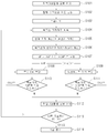
도 7은 본 발명에 따른 곡블록 협소구간 작업이 가능한 용접로봇 시스템의 제어방법을 보인 흐름도로서, (a) 작업대상물에 용접로봇(1)을 위치시키는 단계(S101); (b) 틸팅수단(30)으로 상기 용접로봇(1)의 각도를 설정하는 단계(S102); (c) 작업 시작 명령이 입력되면, 목표점 위치좌표를 획득하는 단계(S103 ~ S104); (d) 현재 위치를 계산하는 단계(S105); (e) 상기 목표점과 현재 위치와의 거리를 계산하는 단계(S106); (f) 상기 (e)단계에서 계산한 거리 값을 용접로봇 보간과 직선 구간 보간 영역으로 분할하는 단계(S107); (g) 상기 (f)단계에서 분할한 보간 영역별로 축 이동 값을 보간하는 단계(S108 ~ S109); (h) 상기 (g)단계에서 보간한 축 이동 값을 기초로 용접로봇 및 직선 부가 축을 동작시켜 목표점으로 이동하는 단계(S110 ~ S112); (i) 상기 목표 점으로 이동하여 용접 작업을 완료한 후, 다른 목표점이 있는지를 확인하여 다른 목표점이 존재하면 상기 단계 S105로 이동하고, 다른 목표 점이 존재하지 않으면 작업을 종료하는 단계(S113 ~ S114)를 포함한다.FIG. 7 is a flowchart illustrating a control method of a welding robot system capable of performing a narrow block section of a curved block according to the present invention, the method comprising: (a) placing a welding robot 1 on a workpiece (S101); (b) setting the angle of the welding robot (1) with the tilting means (30) (S102); (c) when a task start command is input, obtaining a target point position coordinate (S103 to S104); (d) calculating a current position (S105); (e) calculating a distance between the target point and the current position (S106); (f) dividing the distance value calculated in the step (e) into a welding robot interpolation and a linear region interpolation region (S107); (g) interpolating an axis shift value for each of the interpolation areas divided in the step (f) (S108 to S109); (h) moving the welding robot and the linear part to the target point by operating the axis based on the axis movement value interpolated in the step (g) (S110 to S112); (i) moving to the target point and confirming whether or not there is another target point after completing the welding work, and if there is another target point, proceeding to the step S105; if there is no other target point, ending the work (steps S113 to S114 ).
이와 같이 구성된 본 발명에 따른 곡블록 협소구간 작업이 가능한 용접로봇 시스템의 제어방법을 구체적으로 설명하면 다음과 같다.The control method of the welding robot system capable of performing the narrow block section of the curved block according to the present invention will be described in detail as follows.
도 7과 같은 제어방법은 용접로봇(1)의 로봇 베이스(1)의 내부에 마련된 용접로봇 제어장치에서 수행하는 소프트웨어적인 제어과정을 도시한 것이다.The control method as shown in FIG. 7 shows a software control process performed by the welding robot control device provided inside the
먼저, 단계 S101에서 직선 부가 축(40)과 틸팅 수단(30) 및 용접 로봇(1)을 결합한 용접로봇(1)을 작업대상물의 적당한 위치로 이동시킨다.First, in step S101, the
이어, 단계 S102와 같이 틸팅 수단(30)의 틸팅부(31)를 이용하여 용접로봇(1)의 틸팅 각도를 설정한다. 틸팅 각도는 작업대상물의 용접 부위 기울기를 고려하여 설정하는 것이 바람직하다. 본 발명에서는 용접로봇(1)을 작업대상물의 위치로 이동시킨 후 용접로봇(1)의 틸팅 각도를 조절하는 것으로 설명하였으나, 상기와 역순으로 용접로봇(1)의 틸팅 각도를 설정하는 것도 가능하다. 즉, 틸팅 수단(30)을 직선 부가 축(40)에 결합하고, 틸팅 수단(30)의 틸팅부(31)를 이용하여 용접로봇(1)의 틸팅 각도를 설정한 후, 용접로봇(1)을 틸팅부(31)에 장착하여, 용접로봇(1)의 틸팅 각도를 설정하는 것도 가능하다.Subsequently, the tilting angle of the
다음으로, 단계 S103에서 교시조작기를 통해 용접로봇의 작업 명령이 입력되면, 상기 용접로봇 제어장치에서 단계 S104와 같이 목표 점 위치좌표를 획득한다. 여기서 목표 점 위치 좌표는 용접 끝점으로 로봇 베이스 기준 위치이다.Next, when the work instruction of the welding robot is inputted through the teaching manipulator in step S103, the welding robot control apparatus acquires the target point position coordinates as in step S104. Here, the target point position coordinate is the robot base reference position as the welding end point.
이어, 단계 S105에서 현재 위치를 계산한다. 여기서 현재 위치는 툴(토치) 끝점의 위치를 현재 위치로 계산하는 것이 바람직하다. 즉, 로봇 베이스 좌표 원전을 현재 위치로 계산한다.Then, in step S105, the current position is calculated. Here, the current position is preferably calculated as the current position of the tool (torch) end point. That is, the robot base coordinate source is calculated as the current position.
다음으로, 단계 S106에서 상기 목표 점과 현재 위치와의 거리(ΔP)를 하기의 [수학식 1]을 이용하여 계산한다.Next, in step S106, the distance? P between the target point and the current position is calculated using the following equation (1).
![]()
![]()

여기서 

여기서 P2는 목표점 좌표, P1은 현재 위치 좌표, α는 기울기를 나타낸다.Where P 2 is the target point coordinate, P 1 is the current position coordinate, and α is the slope.
상기 α의 변경으로, 용접로봇 6축과 직선 부가 축의 상대 속도 조절이 가능하고, 작업 대상물에 따라 다른 방향(y, z 방향)으로도 적용하여 3방향 동시에 동작을 구현하는 것도 가능하다.With the change of?, It is possible to adjust the relative speed between the axis of the welding robot 6 and the straight line portion, and to operate in three directions simultaneously by applying the welding robot in different directions (y and z directions) according to the workpiece.
다음으로, 단계 S107에서 상기 단계에서 계산한 거리값을 용접로봇 보간(αΔP)과 직선 구간 보간((1-α)ΔP) 영역으로 분할한다. Next, in step S107, the distance value calculated in the above step is divided into the welding robot interpolation alpha DELTA P and the linear interpolation ((1 - alpha) DELTA P).
이어, 단계 S108에서는 상기 용접로봇의 6축 동작 보간 값을 기초로 6축을 보간하고, 단계 S109에서 상기 직선 부가 축의 동작 보간 값을 기초로 직선 부가 축을 보간한다. 이때 용접로봇의 6축 보간과 직선 부가 축의 동작 보간은 동기화를 통해 동시 이루어지는 것이 바람직하다.In step S108, six axes are interpolated based on the six-axis motion interpolation value of the welding robot. In step S109, the straight line interpolates the axis on the basis of the motion interpolation value of the axis. At this time, it is preferable that the 6-axis interpolation of the welding robot and the operation interpolation of the linear part axis are performed simultaneously through synchronization.
다음으로, 단계 S110 및 단계 S111에서 각각 보간한 축 이동 값을 기초로 용접로봇 및 직선 부가 축을 동작시켜 목표 점으로 동시 동작을 하면서, 목표 점으로 이동을 하면서 단계 S112와 같이 용접 작업을 완료한다.Next, based on the axis movement values interpolated in steps S110 and S111, the welding robots and the straight line sections are operated simultaneously to the target point, and the welding operation is completed as in step S112 while moving to the target point.
이어, 하나의 목표 점까지의 용접 작업이 완료되면, 단계 S113으로 이동하여 다른 목표 점이 있는지를 확인하여 다른 목표 점이 존재하면 상기 단계 S105로 이동하고, 다른 목표 점이 존재하지 않으면 단계 S114로 이동하여 작업을 종료하게 되는 것이다.Then, when the welding operation to one target point is completed, the process goes to step S113 to check whether there is another target point. If there is another target point, the process goes to step S105. If there is no other target point, .
이와 같이 본 발명은 용접로봇의 6 자유도와 직선 부가 축의 1 자유도를 포함하여 용접로봇을 제어함으로써, 용접 영역의 확장이 가능하고, 자연스럽게 용접로봇과 직선 부가 축을 동시 동작시키는 것이 가능해지게 되는 것이다.As described above, according to the present invention, the welding robot can be expanded by controlling the welding robot including the six degrees of freedom of the welding robot and the one-degree-of-freedom linear portion of the axis, and the welding robot and the straight line portion can naturally operate simultaneously.
이상 본 발명자에 의해서 이루어진 발명을 상기 실시 예에 따라 구체적으로 설명하였지만, 본 발명은 상기 실시 예에 한정되는 것은 아니고 그 요지를 이탈하지 않는 범위에서 여러 가지로 변경 가능한 것은 이 기술분야에서 통상의 지식을 가진 자에게 자명하다.While the present invention has been particularly shown and described with reference to exemplary embodiments thereof, it is to be understood that the invention is not limited to the disclosed exemplary embodiments, but, on the contrary, It is obvious to those who have.
1: 용접 로봇
10: 로봇 베이스
20: 로봇팔
30: 틸팅 수단
31: 틸팅부
40: 직선 부가 축
41: 프레임
42: 이동 부재1: welding robot
10: Robot base
20: Robotic arm
30: tilting means
31: tilting portion
40:
41: frame
42: moving member
Claims (12)
로봇 베이스와 다관절 로봇팔 및 토치를 포함하고, 자유도를 이용하여 곡블록 용접을 수행하는 용접로봇; 및
상기 용접로봇의 베이스와 결합하며, 상기 용접로봇의 직선 자유도를 부가하여 작업 영역을 확장하는 직선 부가 축을 포함하는 것을 특징으로 하는 곡블록 협소 구간 작업이 가능한 용접로봇 시스템.
A welding robot system capable of working in a narrow block section,
A welding robot including a robot base and a multi-joint robot arm and a torch, and performing a curved block welding using a degree of freedom; And
Wherein the welding robot includes a straight line portion coupled to a base of the welding robot and extending a work area by adding a linear degree of freedom of the welding robot.
The welding robot system according to claim 1, wherein the linear portion is simultaneously operated in a translational motion with the welding robot.
The welding robot system according to claim 1 or 2, wherein the linear shafts include a moving member for advancing or retracting the welding robot in a linear direction.
로봇 베이스와 다관절 로봇팔 및 토치를 포함하고, 자유도를 이용하여 곡블록 용접을 수행하는 용접로봇;
상기 용접로봇의 베이스와 결합하며, 곡블록 기울기에 따라 상기 용접로봇을 틸팅시키는 틸팅수단; 및
상기 틸팅수단과 결합하며, 상기 용접로봇에 직선 자유도를 부가하여 작업 영역을 확장하는 직선 부가 축을 포함하는 것을 특징으로 하는 곡블록 협소 구간 작업이 가능한 용접로봇 시스템.
A welding robot system capable of working in a narrow block section,
A welding robot including a robot base and a multi-joint robot arm and a torch, and performing a curved block welding using a degree of freedom;
Tilting means coupled to the base of the welding robot and tilting the welding robot according to a tilting block tilt; And
Wherein the welding robot system includes a straight line portion coupled to the tilting means and extending a work area by adding a linear degree of freedom to the welding robot.
The welding robot system according to claim 4, wherein the tilting unit includes a tilting unit for adjusting a tilting angle of the welding robot.
The welding robot system according to claim 4, wherein the linear portion is simultaneously operated by translational movement with the welding robot.
[6] The welding robot system according to claim 6, wherein the linear shafts include a tilting means and a moving member for advancing or retracting the welding robot mounted on the tilting means in a linear direction.
(a) 작업대상물에 용접로봇을 위치시키는 단계;
(b) 틸팅수단으로 상기 용접로봇의 각도를 설정하는 단계;
(c) 작업 시작 명령이 입력되면, 목표점 위치좌표를 획득하는 단계;
(d) 현재 위치를 계산하는 단계;
(e) 상기 목표 점과 현재 위치와의 거리를 계산하는 단계;
(f) 상기 (e)단계에서 계산한 거리값을 용접로봇 보간과 직선 구간 보간 영역으로 분할하는 단계;
(g) 상기 (f)단계에서 분할한 보간 영역별로 축 이동 값을 보간하는 단계; 및
(h) 상기 (g)단계에서 보간한 축 이동 값을 기초로 용접로봇 및 직선 부가 축을 동작시켜 목표 점으로 이동하는 단계를 포함하는 것을 특징으로 하는 곡블록 협소 구간 작업이 가능한 용접로봇 시스템의 제어방법.
A control method of a welding robot system capable of working in a narrow block section,
(a) positioning a welding robot on a workpiece;
(b) setting an angle of the welding robot with tilting means;
(c) if a task start command is input, acquiring a target point position coordinate;
(d) calculating a current position;
(e) calculating a distance between the target point and the current position;
(f) dividing the distance value calculated in the step (e) into welding robot interpolation and straight line interpolation areas;
(g) interpolating an axis shift value for each interpolation area divided in step (f); And
(h) moving the welding robot and the linear part to the target point by operating the axis based on the axis movement value interpolated in step (g). Way.
The method according to claim 8, wherein the step (d) calculates the position of the tool end point as a current position.
여기서 P2는 목표점 좌표, P1은 현재 위치 좌표, α는 기울기를 나타낸다.
[8] The method of claim 8, wherein step (e) calculates a distance [Delta] P between a target position and a current position using the following equation.
Where P 2 is the target point coordinate, P 1 is the current position coordinate, and α is the slope.
[8] The method of claim 8, wherein step (g) comprises: (g1) interpolating the robot's six axes; (g2) interpolating the axis of the straight line.
[9] The method of claim 8, wherein step (h) comprises simultaneously operating the welding robots and the linear parts in a synchronous motion in a translational motion.
Priority Applications (1)
| Application Number | Priority Date | Filing Date | Title |
|---|---|---|---|
| KR1020160066607A KR101808295B1 (en) | 2016-05-30 | 2016-05-30 | Welding robot system control method for working of curved block narrow range |
Applications Claiming Priority (1)
| Application Number | Priority Date | Filing Date | Title |
|---|---|---|---|
| KR1020160066607A KR101808295B1 (en) | 2016-05-30 | 2016-05-30 | Welding robot system control method for working of curved block narrow range |
Publications (2)
| Publication Number | Publication Date |
|---|---|
| KR20170135150A true KR20170135150A (en) | 2017-12-08 |
| KR101808295B1 KR101808295B1 (en) | 2017-12-12 |
Family
ID=60919646
Family Applications (1)
| Application Number | Title | Priority Date | Filing Date |
|---|---|---|---|
| KR1020160066607A KR101808295B1 (en) | 2016-05-30 | 2016-05-30 | Welding robot system control method for working of curved block narrow range |
Country Status (1)
| Country | Link |
|---|---|
| KR (1) | KR101808295B1 (en) |
Cited By (2)
| Publication number | Priority date | Publication date | Assignee | Title |
|---|---|---|---|---|
| CN111979957A (en) * | 2020-09-01 | 2020-11-24 | 广东新江永安建设工程有限公司 | Automatic laying device of highway division board for municipal construction |
| CN112720433A (en) * | 2021-01-21 | 2021-04-30 | 广州明瑶科技有限公司 | Welding robot with positioning function |
Families Citing this family (2)
| Publication number | Priority date | Publication date | Assignee | Title |
|---|---|---|---|---|
| KR102223886B1 (en) | 2019-07-04 | 2021-03-05 | 주식회사 신독 | Multi-joint robot tilting device for working radius extension |
| KR102201397B1 (en) | 2020-11-02 | 2021-01-11 | 주식회사 태영금속 | Welding system |
Family Cites Families (2)
| Publication number | Priority date | Publication date | Assignee | Title |
|---|---|---|---|---|
| KR100535627B1 (en) | 2003-08-08 | 2005-12-08 | 한국원자력연구소 | Reactor Vessel Inspection Tool |
| KR101118225B1 (en) | 2009-08-12 | 2012-03-19 | 대우조선해양 주식회사 | Welding robot for constructing a body of a ship |
-
2016
- 2016-05-30 KR KR1020160066607A patent/KR101808295B1/en active IP Right Grant
Cited By (2)
| Publication number | Priority date | Publication date | Assignee | Title |
|---|---|---|---|---|
| CN111979957A (en) * | 2020-09-01 | 2020-11-24 | 广东新江永安建设工程有限公司 | Automatic laying device of highway division board for municipal construction |
| CN112720433A (en) * | 2021-01-21 | 2021-04-30 | 广州明瑶科技有限公司 | Welding robot with positioning function |
Also Published As
| Publication number | Publication date |
|---|---|
| KR101808295B1 (en) | 2017-12-12 |
Similar Documents
| Publication | Publication Date | Title |
|---|---|---|
| KR101808295B1 (en) | Welding robot system control method for working of curved block narrow range | |
| EP1749621B1 (en) | Robot programming device | |
| US20150090769A1 (en) | Welding Apparatus | |
| JP5980867B2 (en) | Robot teaching device that teaches robots offline | |
| JP5458769B2 (en) | Robot control device | |
| US10265860B2 (en) | Method and apparatus for controlling operations of robot | |
| US6283361B1 (en) | General-purpose jig | |
| CN110545952B (en) | Robot system and work line provided with same | |
| US20040054437A1 (en) | Robot control apparatus | |
| WO2014123054A1 (en) | Robot control device and robot control method | |
| US10022868B2 (en) | Inverse kinematic solution for multi-joint link mechanism, and teaching-data creating device using the inverse kinematic solution | |
| JP2020082285A (en) | Interference checking method for plural robots, and robot system | |
| JP5056241B2 (en) | Robot system controller | |
| JP2011131326A (en) | Method for avoiding interference of robot arm | |
| JP7072489B2 (en) | Welding equipment and welding method | |
| JP2001318715A (en) | Teaching method and device for robot for welding | |
| JP2019166578A (en) | Setting device for robot operation program, robot and robot control method | |
| JP2007316862A (en) | Servo driver and servo system with multiple axes | |
| JP2019094665A (en) | Boring support device | |
| JPH09201784A (en) | Teaching device for robot | |
| CN115305980B (en) | Method, processor, device and engineering equipment for controlling folding arm type arm support | |
| JP2732034B2 (en) | Robot controller | |
| JPH08323665A (en) | Instruction controller of robot | |
| JPH06236206A (en) | Control method for industrial robot mounted on turn table | |
| JP5609769B2 (en) | Robot system |
Legal Events
| Date | Code | Title | Description |
|---|---|---|---|
| E701 | Decision to grant or registration of patent right | ||
| GRNT | Written decision to grant |