KR20170134026A - Heat Transfer Device - Google Patents
Heat Transfer Device Download PDFInfo
- Publication number
- KR20170134026A KR20170134026A KR1020160065670A KR20160065670A KR20170134026A KR 20170134026 A KR20170134026 A KR 20170134026A KR 1020160065670 A KR1020160065670 A KR 1020160065670A KR 20160065670 A KR20160065670 A KR 20160065670A KR 20170134026 A KR20170134026 A KR 20170134026A
- Authority
- KR
- South Korea
- Prior art keywords
- heat transfer
- heat
- transfer medium
- user
- generating device
- Prior art date
- Legal status (The legal status is an assumption and is not a legal conclusion. Google has not performed a legal analysis and makes no representation as to the accuracy of the status listed.)
- Granted
Links
Images


Classifications
-
- B—PERFORMING OPERATIONS; TRANSPORTING
- B60—VEHICLES IN GENERAL
- B60N—SEATS SPECIALLY ADAPTED FOR VEHICLES; VEHICLE PASSENGER ACCOMMODATION NOT OTHERWISE PROVIDED FOR
- B60N2/00—Seats specially adapted for vehicles; Arrangement or mounting of seats in vehicles
- B60N2/56—Heating or ventilating devices
- B60N2/5678—Heating or ventilating devices characterised by electrical systems
-
- F—MECHANICAL ENGINEERING; LIGHTING; HEATING; WEAPONS; BLASTING
- F28—HEAT EXCHANGE IN GENERAL
- F28F—DETAILS OF HEAT-EXCHANGE AND HEAT-TRANSFER APPARATUS, OF GENERAL APPLICATION
- F28F3/00—Plate-like or laminated elements; Assemblies of plate-like or laminated elements
- F28F3/02—Elements or assemblies thereof with means for increasing heat-transfer area, e.g. with fins, with recesses, with corrugations
- F28F3/022—Elements or assemblies thereof with means for increasing heat-transfer area, e.g. with fins, with recesses, with corrugations the means being wires or pins
-
- B—PERFORMING OPERATIONS; TRANSPORTING
- B60—VEHICLES IN GENERAL
- B60N—SEATS SPECIALLY ADAPTED FOR VEHICLES; VEHICLE PASSENGER ACCOMMODATION NOT OTHERWISE PROVIDED FOR
- B60N2/00—Seats specially adapted for vehicles; Arrangement or mounting of seats in vehicles
- B60N2/56—Heating or ventilating devices
-
- B—PERFORMING OPERATIONS; TRANSPORTING
- B60—VEHICLES IN GENERAL
- B60N—SEATS SPECIALLY ADAPTED FOR VEHICLES; VEHICLE PASSENGER ACCOMMODATION NOT OTHERWISE PROVIDED FOR
- B60N2/00—Seats specially adapted for vehicles; Arrangement or mounting of seats in vehicles
- B60N2/58—Seat coverings
-
- H10W40/257—
Landscapes
- Engineering & Computer Science (AREA)
- Mechanical Engineering (AREA)
- Aviation & Aerospace Engineering (AREA)
- Transportation (AREA)
- Physics & Mathematics (AREA)
- Thermal Sciences (AREA)
- General Engineering & Computer Science (AREA)
- Cooling Or The Like Of Semiconductors Or Solid State Devices (AREA)
- Thermotherapy And Cooling Therapy Devices (AREA)
- Central Heating Systems (AREA)
Abstract
실시예는 열전달 장치로서, 사용자가 설정한 세기의 열을 발생시키는 열발생 장치, 상기 열발생 장치를 덮으면서 사용자의 신체와 접촉되는 커버 및 상기 열발생 장치와 상기 커버 사이에서 마련되며 상기 열발생 장치에서 발생되는 열을 전달하는 열전달 매개체를 포함하고, 상기 열전달 매개체는 소정 길이의 단일 와이어가 얽혀져 소정의 너비과 높이를 갖도록 형성된 구조물이며, 사용자의 신체와 접촉시 축방향으로의 압축이 이루어져 포아송 비(Poisson's ratio)가 0.5 이상으로 나타나는 구조물일 수 있다. 따라서, 열을 발생시키는 장치의 구조적인 변경이 필요하지 않으며 열발생 장치와 접촉되는 물질만을 변경함으로써, 발생되는 열을 더욱 빠르게 사용자 신체에 도달하게 할 수 있다.An embodiment is a heat-conducting apparatus comprising: a heat-generating device for generating heat of a user-set intensity; a cover for contacting the user's body while covering the heat-generating device; The heat transfer medium is a structure formed by entangling a single wire of a predetermined length to have a predetermined width and height. When the heat transfer medium contacts the user's body, the heat transfer medium is compressed in the axial direction, And a Poisson's ratio of 0.5 or more. Thus, it is possible to make the generated heat reach the user's body more quickly by changing only the material which is in contact with the heat generating device, without requiring a structural change of the device generating heat.
Description
본 발명은 열전달 장치에 관한 것으로, 보다 상세하게는 사용자 신체의 일부가 접촉하는 지점에서 열전달이 더욱 잘 이루어지는 열전달 장치에 관한 것이다.BACKGROUND OF THE INVENTION 1. Field of the Invention The present invention relates to a heat transfer apparatus, and more particularly to a heat transfer apparatus in which heat transfer is performed at a point where a part of a user's body contacts.
현대 사회에서 열전달률이 높은 소재는 효율적인 에너지 사용이라는 관점에서 중요하다. IT 기술의 발전에 따라 전자소재의 경우 소형화, 집적화 및 높은 효율 등으로 인해 기기에서 발생하는 열을 효과적으로 제어하기 위해 일정수준 이상의 열전달률이 반드시 필요하다. 이를 확보하기 위해 열전도성 필러의 복합화 공정뿐만 아니라, 새로운 복합재료의 제조, 새로운 열전도성 입자의 합성, 열전도성 입자의 구조 및 형태 제어, 매트릭스 수지 내의 배향성 제어 등 여러 연구가 진행되고 있지만 이는 시간적 어려움과 함께 경제적으로도 비용이 많이 들 수 있다는 단점이 있다.Materials with high heat transfer rates in modern society are important in terms of efficient energy use. Due to the development of IT technology, electronic materials require a certain level of heat transfer rate to effectively control the heat generated by the device due to miniaturization, integration and high efficiency. In order to achieve this, various researches such as the production of new composite materials, the synthesis of new thermally conductive particles, the structure and shape control of thermally conductive particles, and the orientation control in matrix resin have been carried out in addition to the complex process of thermally conductive filler, And it can be economically costly.
본 발명은 상술한 문제를 해결하기 위해 포아송 비가 1에 근접하는 물질을 열전달 매개체로 사용하여 형상 변화에 따라 발생되는 열 전달 경로를 바꾸어주는 열전달 장치를 제공하는데 그 목적이 있다.An object of the present invention is to provide a heat transfer device that uses a material having a Poisson's ratio close to 1 as a heat transfer medium to change the heat transfer path generated according to the shape change.
본 발명은 사용자 신체의 일부가 접촉하는 부분에서의 열전달이 더욱 가속화되어 에너지 효율을 향상시킬 수 있는 열전달 장치를 제공하는데 그 목적이 있다.An object of the present invention is to provide a heat transfer device capable of enhancing energy efficiency by further accelerating heat transfer at a portion where a user's body touches.
본 발명의 실시예는 열전달 장치로서, 사용자가 설정한 세기의 열을 발생시키는 열발생 장치; 상기 열발생 장치를 덮으면서 사용자의 신체와 접촉되는 커버; 상기 열발생 장치와 상기 커버 사이에서 마련되며 상기 열발생 장치에서 발생되는 열을 전달하는 열전달 매개체;를 포함하고, 상기 열전달 매개체는 소정 길이의 단일 와이어가 얽혀져 소정의 너비과 높이를 갖도록 형성된 구조물이며, 사용자의 신체와 접촉시 축방향으로의 압축이 이루어져 포아송 비(Poisson's ratio)가 0.5 이상으로 나타나는 구조물일 수 있다. An embodiment of the present invention is a heat-conducting apparatus comprising: a heat-generating device for generating heat of a strength set by a user; A cover which contacts the body of the user while covering the heat generating device; And a heat transfer medium provided between the heat generating device and the cover to transmit heat generated in the heat generating device, wherein the heat transfer medium is a structure formed by entangling a single wire of a predetermined length to have a predetermined width and height , And may be a structure in which a compression in the axial direction is made when the user contacts the user's body and Poisson's ratio is 0.5 or more.
그리고, 상기 열전달 매개체를 이루는 와이어는 구리, 니티놀 또는 고분자 중 어느 하나로 이루어질 수 있다. The wire forming the heat transfer medium may be made of copper, nitinol or a polymer.
그리고, 상기 열전달 매개체는 사용자의 신체가 접촉하는 부분에 복수개가 배열될 수 있다. In addition, a plurality of the heat transfer media may be arranged in a portion where the user's body contacts.
그리고, 상기 열전달 매개체를 이루는 와이어는 직경이 500㎛이고, 20m의 단일 와이어로 이루어질 수 있다. The wire forming the heat transfer medium may have a diameter of 500 mu m and a single wire of 20 m.
그리고, 상기 열전달 매개체는 압축이 발생하는 경우 두께가 감소하고 상기 열발생 장치와 접촉하는 면적이 증가하는 특징이 있다. The heat transfer medium is characterized in that, when compression occurs, the thickness decreases and the area of contact with the heat generating device increases.
그리고, 상기 열전달 매개체는 압축이 발생한 부분의 열전달 경로가 압축이 발생하지않은 부분의 열전달 경로보다 짧아지는 것을 특징으로 한다. The heat transfer medium is characterized in that a heat transfer path of a portion where compression occurs is shorter than a heat transfer path of a portion where compression has not occurred.
그리고, 상기 열전달 매개체는 인장시 포아송 비가 0에 근접하며, 두께가 증가하고 상기 열발생 장치와 접촉하는 면적이 감소하는 특징이 있다.The heat transfer medium is characterized in that the Poisson's ratio at the time of pulling is close to zero, the thickness increases, and the area of contact with the heat generating device is reduced.
그리고, 상기 열전달 매개체에 압축이 가해진 후에 압축이 풀어지는 경우 원래의 형상으로 복원되면서 내부에 저장된 열이 일정한 수준으로 유지될 수 있다.When the heat transfer medium is decompressed after being compressed, the heat stored in the heat transfer medium can be maintained at a constant level while being restored to its original shape.
본 발명의 실시예에 따르면, 열을 발생시키는 장치의 구조적인 변경이 필요하지 않으며 열발생 장치와 접촉되는 물질만을 변경함으로써, 발생되는 열을 더욱 빠르게 사용자 신체에 도달하게 할 수 있다. According to the embodiment of the present invention, it is possible to make the generated heat reach the user's body more quickly by changing only the material which is in contact with the heat generating device without requiring a structural change of the device for generating heat.
본 발명의 실시예에 따르면, 열발생 장치가 동일한 열을 발생시에도 사용자의 접촉에 의해 압력이 변한 부분이 우선적으로 열을 빨리 전달시킬 수 있는 구조로 변경되므로, 열전달시의 에너지 효율성을 향상시킬 수 있다.According to the embodiment of the present invention, even when the heat generating apparatus generates the same heat, the portion where the pressure is changed by the contact of the user is changed to a structure that can transmit heat quickly, so that the energy efficiency at the time of heat transfer can be improved have.
도 1은 실시예의 열전달 장치에 적용될 수 있는 열전달 물질의 제조과정을 나타낸 도면
도 2는 실시예의 열전달 물질의 특성을 나타낸 그래프
도 3은 실시예의 열전달 물질의 특성을 나타낸 그래프
도 4는 실시예에서 열전달 매개체로 적용하고자 하는 열전달 구조체의 예시를 나타내 도면
도 5는 실시예에 따른 열전달 장치를 나타낸 도면
도 6은 실시예에 따른 열전달 장치의 열전달 경로의 변경을 나타낸 도면1 is a view showing a manufacturing process of a heat transfer material applicable to the heat transfer apparatus of the embodiment
2 is a graph showing the characteristics of the heat transfer material of the embodiment
3 is a graph showing the characteristics of the heat transfer material of the embodiment
Figure 4 illustrates an example of a heat transfer structure to be applied as a heat transfer medium in the embodiment
5 is a view illustrating a heat transfer device according to an embodiment;
6 shows a modification of the heat transfer path of the heat transfer device according to the embodiment
이하 첨부된 도면들을 참조하여 본 발명의 실시예들을 상세하게 설명하지만, 본 발명의 실시예에 의해 제한되거나 한정되는 것은 아니다. 본 발명을 설명함에 있어서, 공지된 기능 혹은 구성에 대해 구체적인 설명은 본 발명의 요지를 명료하게 하기 위해 생략될 수 있다. The embodiments of the present invention will be described in detail with reference to the accompanying drawings, but the present invention is not limited to these embodiments. In describing the present invention, a detailed description of well-known functions or constructions may be omitted for the sake of clarity of the present invention.
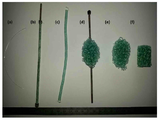
도 1은 실시예의 열전달 장치에 적용될 수 있는 열전달 물질의 제조과정을 나타낸 도면이다. 실시예의 열전달 장치에 적용될 수 있는 열전달 물질은 가역적 다일레턴시(dilatancy)를 갖는 얽힌 구조를 갖는 물질로 형성될 수 있으며, 이 물질에 대한 특성과 제조 방법 등이 2015년에 발표된 논문 “David Rodney, Benjamin Gadot, Oriol Riu Martinez, Sabine Rolland du Roscoat and Laurent Orgeas Reversible dilatancy in entangled single-wire materials” 에 공개된 바 있다. 1 is a view showing a process of manufacturing a heat transfer material applicable to the heat transfer device of the embodiment. The heat transfer material that can be applied to the heat transfer device of the embodiment can be formed of a substance having an entangled structure having reversible dilatancy. The characteristics and manufacturing method of the heat transfer material can be described in " David Rodney, Benjamin Gadot, Oriol Riu Martinez, Sabine Rolland du Roscoat and Laurent Orgeas Reversible dilatancy in entangled single-wire materials.
실시예에 따른 열전달 장치에 적용하고 하는 상기의 물질은 특히 포아송(Poisson) 비가 1에 근접하는 물질로 그 제조 방법은 다음과 같다. The material to be applied to the heat transfer device according to the embodiment is a material having a Poisson ratio close to 1, and a manufacturing method thereof is as follows.
우선, 고분자로 이루어진 와이어를 봉에 감은 후에 볼트로 와이어의 단부를 고정한다. 그리고, 160℃에서 15분간 가열한 후에 볼트를 풀고 봉을 제거하여 와이어를 코일 형태로 만든다. 코일 상태의 와이어를 봉 주위에서 얽히게 하여 내부가 촘촘하지 않은 상태의 공모양을 만든다. 이어서, 봉을 제거하고 압착다이스에 넣은 후에 160℃에서 60분간 압력을 가하면 (f)와 같이 원통형의 구조가 형성된다. 즉, 원통형으로 형성된 구조체 내부에 하나의 와이어가 복잡하게 얽혀있는 구조로 형성될 수 있다. First, a wire made of a polymer is wound around a rod, and then the end of the wire is fixed with a bolt. After heating at 160 ° C for 15 minutes, loosen the bolts and remove the rods to make the wire into a coil. The wire in the coil state is entangled around the rod to form a ball shape in which the inside is not densely formed. Subsequently, when the rod is removed and put into the compression die, the pressure is applied at 160 DEG C for 60 minutes to form a cylindrical structure as shown in (f). That is, it may be formed in a structure in which one wire is intricately entangled within a structure formed in a cylindrical shape.
상술한 바와 같이 제조된 물질은 하나의 와이어가 얽혀져서 만들어진 것으로 포아송 비가 0.5 이상으로 나타나는 특징을 가진다. 일반적인 물질의 경우 포아송 비는 0~0.5 사이값을 가지며, 포아송비가 큰 것으로 생각되는 고무 또한 포아송 비가 0.46~0.49의 값을 가진다. The material manufactured as described above is characterized by being formed by entangling one wire and having Poisson's ratio of 0.5 or more. Poisson's ratio is between 0 and 0.5, and Poisson's ratio is 0.46 ~ 0.49.
포아송 비(Poisson's ratio)는 재료 내부에 생기는 수직 응력에 의한 가로 변형과 세로 변형의 비를 나타내는 것으로, 포아송 비가 증가한다는 것은 축 하중이 작용할 때 폭 방향 변형률이 길이 방향 변형률의 변화량보다 크다는 의미이다. The Poisson's ratio indicates the ratio of transverse strain to transverse strain due to normal stress in the material. The increase in Poisson's ratio means that the transverse strain is greater than the longitudinal strain.
동일한 물질에서 열전달이 크게 일어나기 위해서는 열이 전달되는 구조체의 면적은 넓어져야 하며, 열이 이동하는 거리인 구조체의 두께는 작아져야 하는데, 이는 열전달률과 관련된 다음의 식을 통해서도 알 수 있다.In order for heat transfer to occur in the same material, the area of the structure to which the heat is transferred must be widened, and the thickness of the structure, ie, the distance of heat transfer, must be reduced.
![]()
![]()
k: 열전도율(W/m·K), A: 면적(m2), L: 길이(m), T: 온도(K)k: thermal conductivity (W / mK), A: area (m 2 ), L: length (m)
수학식 1과 같이 열전달은 A가 클수록, L이 작을수록 크게 나타난다. As shown in Equation (1), heat transfer becomes larger as A becomes larger and L becomes smaller.
실시예는 상기와 같이 제조된 구조체를 열전달을 매개하는 수단으로 활용하고자 하며, 상술한 바와 같이 열전달을 향상시킬 수 있는 상기 구조체의 특징에 대해 좀 더 살펴본다. The embodiment will utilize the structure thus manufactured as a means for mediating heat transfer, and the features of the structure capable of improving heat transfer as described above will be further described.
도 2는 실시예의 열전달 물질의 특성을 나타낸 그래프이다. 단일 와이어는 구리, 니티놀, 고분자 등을 사용하는 것이 바람직하며, 도 2 내지 도 3 그래프에서 a는 구리, b는 니티놀, c는 고분자를 나타내고 축방향으로 압축 또는 완화(인장)를 반복하는 사이클을 수행하면서 이에 대한 스트레인을 측정한 것이다. 2 is a graph showing the characteristics of the heat transfer material of the embodiment. It is preferable to use copper, nitinol, polymer or the like as the single wire. In the graphs of FIGS. 2 to 3, a represents copper, b represents nitinol, and c represents a polymer. A cycle of repeating compression or relaxation And the strain was measured.
(a)는 축방향의 스트레인(strain)에 대한 측방향의 스트레인을 나타낸 것이고 (b)는 축방향의 스트레인에 대한 체적 스트레인을 나타낸 것이다. (a)를 참조하면, 측면 스트레인은 구조체에 압축이 가해졌을 때(축방향 스트레인이 음수값을 가질 때) 양수값을 가지는 것을 알 수 있는데, 이는 열전달 구조체가 측면 방향으로 확장되는 것으로 이해될 수 있다. (a) shows the lateral strain for the axial strain and (b) shows the volume strain for the axial strain. (a), it can be seen that the lateral strain has a positive value when the structure is subjected to compression (when the axial strain has a negative value), which can be understood to be the lateral expansion of the heat transfer structure have.
(b)를 참조하면, 구조체는 압축이 가해지는 상태에서 체적 스트레인이 음수값을 가져야 할 것으로 생각되지만 양수값을 나타내며, 이러한 체적 증가는 압축으로 인한 체적 팽창을 나타낸다고 볼 수 있다. 또한, 팽창의 대부분은 고분자(PA), 니티놀(NiTi)이 얽힌 와이어 구조물에 압축이 풀어질 때 정상 상태로 회복된다. (b), the structure is considered to have a negative value of volume strain in the state of compression, but represents a positive value, and this volume increase can be regarded as a volume expansion due to compression. Further, most of the expansion is restored to a normal state when the polymer structure (PA) and the nitinol (NiTi) are intertwined with the wire structure.
도 3은 실시예의 열전달 물질의 특성을 나타낸 그래프로, 축방향의 스트레인에 대한 포아송 함수(Poisson's function) 값을 나타낸 것이다. 구조체의 체적 변화는 포아송 함수로 표현될 수 있다. 포아송 함수는 압축과 인장 상태에 따라 대칭적인 분포를 나타냄을 알 수 있는데, 압축시 니티놀과 고분자의 경우에는 1을 초과하여 증가하며 구리의 경우에는 이보다 약간 낮은 0.75의 값을 가지지만 비슷한 경향을 나타낸다고 볼 수 있다. 인장시 니티놀과 고분자는 포아송 함수값이 서서히 0으로 수렴하며, 구리의 경우 마이너스 값을 가지는 것을 알 수 있다. FIG. 3 is a graph showing the characteristics of the heat transfer material in the embodiment, and shows a Poisson's function value for strain in the axial direction. The volume change of the structure can be expressed as a Poisson function. The Poisson function shows a symmetrical distribution according to compression and tensile conditions. Compressed nitinol and polymer increase by more than 1, and copper has a slightly lower value of 0.75 can see. It can be seen that the Poisson function value gradually converges to zero at the time of tensile and the ninethol and the polymer have a negative value in the case of copper.
상술한 바와 같이 구리, 니티놀, 고분자 중 어느 하나로 이루어진 와이어가 얽혀져서 형성된 구조물은 축방향으로 압축력이 작용하는 경우에 포아송 함수값이 1에 근접하게 되며, 이는 측면방향으로 급격히 확장되고 길이방향으로는 급격히 줄어들게 되는 성질을 가진다. 상기 구조물의 이러한 특성은 수학식 1에서 살펴본 바와 같이 열전달률을 향상시킬 수 있는 매개체로서의 역할을 할 수 있다. As described above, a structure formed by entangling wires made of any one of copper, nitinol, and polymer has a Poisson function value close to 1 when a compressive force acts in the axial direction, which rapidly expands in the lateral direction, It has a property of sharply decreasing. This characteristic of the structure can serve as a medium capable of improving the heat transfer rate as shown in Equation (1).
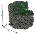
도 4는 실시예에서 열전달 매개체로 적용하고자 하는 열전달 구조체의 예시를 나타내 도면이다. 도 4를 참조하면, L의 직경을 가지며 H의 높이를 갖는 원통 형상으로 코일형상의 와이어가 무질서하게 얽혀진 구조체가 개시되며, 상기 구조체는 20m의 단일 와이어가 얽혀진 형태이고 와이어의 직경은 500㎛로 형성될 수 있으나 이에 한정되지는 않는다. 또한, 상기 와이어는 구리, 니티놀 또는 고분자 중 어느 하나일 수 있다. FIG. 4 illustrates an example of a heat transfer structure to be applied as a heat transfer medium in an embodiment. Referring to FIG. 4, there is disclosed a structure in which a coiled wire is entangled entangled in a cylindrical shape having a diameter of L and a height of H, wherein the structure has a single wire of 20 m intertwined and a diameter of 500 But it is not limited thereto. In addition, the wire may be any one of copper, nitinol, and a polymer.
도 5는 실시예에 따른 열전달 장치를 나타낸 도면이다. 5 is a view illustrating a heat transfer device according to an embodiment.
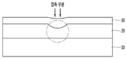
도 5를 참조하면, 실시예의 열전달 장치는 사용자가 설정한 세기의 열을 발생시키는 열발생 장치(10), 상기 열발생 장치를 덮으면서 사용자의 신체와 접촉되는 커버(30) 및 상기 열발생 장치와 상기 커버 사이에서 마련되어 상기 열발생 장치에서 발생되는 열을 전달하는 열전달 매개체(20)를 포함할 수 있다. Referring to FIG. 5, the heat transfer device of the embodiment includes a
상기 열발생 장치는(10)는 전력에 의해 열을 발생시키는 전열선일 수 있으나 이에 한정되지 않으며 열을 발생시키는 모든 구조체를 포함할 수 있다. 또한, 상기 열전달 매개체에 사용자의 신체가 접촉되면, 사용자의 하중이 상기 열전달 매개체를 이루는 구조체에 전달되어 하중이 전달되는 부분의 형상을 변화시킬 수 있다는 것을 의미한다. The
상기 열전달 매개체(20)는 소정 길이의 단일 와이어가 가역적 다일레턴시(dilatancy)를 가지도록 얽혀진 구조체로 형성될 수 있다. 즉, 사용자의 접촉에 의해 가해지는 압력으로 인해 상기 구조체의 두께는 감소하고 길이와 너비는 증가하게 되므로, 도 5에 개시된 바와 같이 접촉 부분에서는 열전달률이 커질 수 있다. The
상기 열전달 매개체(20)는 사용자의 신체 접촉 부위가 대면적일 경우, 즉 열발생 장치의 면적이 크게 형성될 경우, 와이어의 길이를 조절하여 일체형으로 형성할 수 있다. 일체형 구조는 얽혀진 와이어 구조체를 제조시에 최종적으로 압력을 가해주는 틀의 크기를 열발생 장치의 면적에 대응되도록 설계함으로써 형성될 수 있다.The
또한, 열전달 매개체는 복수개의 구조체가 배열된 구조일 수 있으며, 신체 접촉이 자주 발생하는 영역에만 열전달 구조체를 부분적으로 배치하여 형성할 수도 있다. The heat transfer medium may have a structure in which a plurality of structures are arranged and may be formed by locally arranging the heat transfer structure only in areas where frequent physical contact occurs.
상기 커버(30)는 상기 열전달 매개체를 덮으면서, 사용자 신체의 일부가 접촉되는 경우 열전달 매개체에 압력을 전달할 수 있도록 탄성이 큰 물질로 형성되는 것이 바람직하다. The
도 6은 실시예에 따른 열전달 장치의 열전달 경로의 변경을 나타낸 도면이다. FIG. 6 is a view illustrating a modification of the heat transfer path of the heat transfer device according to the embodiment.
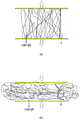
도 6을 참조하면, (a)는 열전달 매개체가 인장되는 경우이며 (b)는 열전달 매개체가 압축되는 경우를 나타낸 것이다. (a)를 참조하면, 열전달 매개체가 화살표의 방향과 같이 상하 방향으로 인장되면 열전달 매개체를 구성하는 얽혀진 와이어는 서로 수평적인 접촉이 우세한 상태가 되며 이때의 열전달 경로는 A와 같이 표시될 수 있다. Referring to FIG. 6, (a) shows a case where the heat transfer medium is pulled, and (b) shows a case where the heat transfer medium is compressed. (a), when the heat transfer medium is stretched in the vertical direction as shown by the arrow, the entangled wires constituting the heat transfer medium are in a state in which horizontal contact is dominant, and the heat transfer path at this time can be expressed as A .
(b)를 참조하면, 열전달 매개체가 화살표의 방향과 같이 압축되면 열전달 매개체를 구성하는 얽혀진 와이어는 서로 수직적인 접촉이 우세한 상태가 되어 이때의 열전달 경로는 B와 같이 표시될 수 있다. (b), when the heat transfer medium is compressed in the direction of the arrow, the entangled wires constituting the heat transfer medium are in a state of vertical contact with each other, and the heat transfer path at this time can be expressed as B.
즉, 사용자의 접촉이 없는 경우에 열전달 매개체가 A의 열전달 경로로 열을 발산시키고 있었다고 가정하면, 사용자의 접촉에 의해 압력이 전달된 부분은 그에 해당되는 얽힌 와이어 구조물의 변형이 발생하게 되므로 열전달 경로가 B와 같이 변경될 수 있다. 와이어 구조물은 반경방향으로 팽창되어 부피가 증가하게 되므로 열전달 면적이 증가하게 된다. 또한, B의 열전달 경로는 A에 비해 짧기 때문에 열저항이 감소한 효과를 나타내며, 이로 인해 접촉 부분은 다른 부분에 비해 사용자에게 빠르게 열을 전달해줄 수 있다. 또한, 가해지는 압력이 제거되는 경우 열전달 매개체의 형상은 원래대로 복원이 이루어지게 되며, 열전달 경로는 다시 A와 같이 형성될 수 있다. That is, assuming that the heat transfer medium is radiating heat to the heat transfer path of A in the absence of the user's touch, the portion of the wire to which the pressure is transferred by the touch of the user causes deformation of the tangled wire structure, Can be changed as B. The wire structure is expanded in the radial direction to increase the volume, thereby increasing the heat transfer area. In addition, since the heat transfer path of B is shorter than that of A, the heat resistance is reduced, so that the contact portion can transmit heat to the user faster than other portions. Also, if the applied pressure is removed, the shape of the heat transfer medium is restored to its original shape, and the heat transfer path can be formed like A again.
실시예의 열전달 장치를 카시트에 적용하는 경우를 예로 들어 설명하면, 차량용 카시트는 특히 겨울에 운전자 또는 탑승자의 체온을 빠른 시간 안에 올려주기 위해 마련되는 부재로, 카시트의 내부에는 열발생을 위한 열선이 지그재그 모양으로 마련되고, 상기 열선과 접촉하는 열전달 매개체 및 이를 덮는 커버가 마련될 수 있다.The case of applying the heat transfer device of the embodiment to a car seat will be described as an example. A car seat is a member provided to raise the temperature of a driver or a passenger in winter in a fast time. In the interior of the car seat, And a heat transfer medium in contact with the heat ray and a cover for covering the heat transfer medium may be provided.
사용자가 카시트에 앉아있는 경우 사용자의 신체가 접촉하는 부분은 압력에 의해 열전달 매개체를 이루는 와이어 구조물의 두께 감소 및 면적 증가로 사용자의 접촉 부위에 빠르게 열전달이 이루어지게 할 수 있다. When the user sits in the car seat, the portion of the user's body contacting can be made to rapidly transfer heat to the contact area of the user due to pressure reduction of the thickness and area of the wire structure constituting the heat transfer medium.
또한, 사용자가 앉아 있지 않을 경우에는 열전달 매개체의 두께가 증가하고 면적이 감소하므로 열발생 장치를 통해 전달되는 열들이 열전달 매개체에 머물러 내부열이 쉽게 빠져나가지 않고 일정 온도를 유지할 수 있다. In addition, when the user is not seated, the thickness of the heat transfer medium increases and the area decreases. Therefore, the heat transmitted through the heat generating device stays in the heat transfer medium, and the internal heat can be easily maintained.
본 실시예의 열전달 장치는 상술한 바와 같이 자동차의 카시트 뿐만 아니라 버스, 지하철 등의 대중교통 수단에 마련되는 의자 또는 자동차의 핸들과 같이 사용자의 접촉에 의해 압력이 전달되는 구조물에 유용하게 접목될 수 있다. The heat transfer device of the present embodiment can be usefully applied to a structure in which pressure is transmitted by a user's contact, such as a chair or a car handle provided in a public transportation means such as a bus or a subway as well as a car seat of the automobile .
상술한 바와 같이 실시예는 열을 발생시키는 장치의 구조적인 변경이 필요하지 않으며 열발생 장치와 접촉되는 물질만을 변경함으로써, 발생되는 열을 더욱 빠르게 사용자 신체에 도달하게 할 수 있다. As described above, the embodiment does not require a structural change of the device for generating heat, and can change the material only in contact with the heat generating device, so that the generated heat can reach the user's body more quickly.
또한, 열발생 장치가 동일한 열을 발생시에도 사용자의 접촉에 의해 압력이 변한 부분이 우선적으로 열을 빨리 전달시킬 수 있는 구조로 변경되므로, 열전달시의 에너지 효율성을 향상시킬 수 있다.In addition, even when the heat generating device generates the same heat, the portion where the pressure changes due to the user's touch is changed to a structure capable of delivering heat quickly, so that the energy efficiency at the time of heat transfer can be improved.
이상에서 본 발명에 대하여 그 바람직한 실시예를 중심으로 설명하였으나 이는 단지 예시일 뿐 본 발명을 한정하는 것이 아니며, 본 발명이 속하는 분야의 통상의 지식을 가진 자라면 본 발명의 본질적인 특성을 벗어나지 않는 범위에서 이상에 예시되지 않은 여러 가지의 변형과 응용이 가능함을 알 수 있을 것이다. 예를 들어, 본 발명의 실시예에 구체적으로 나타난 각 구성 요소는 변형하여 실시할 수 있는 것이다. 그리고 이러한 변형과 응용에 관계된 차이점들은 첨부된 청구 범위에서 규정하는 본 발명의 범위에 포함되는 것으로 해석되어야 할 것이다.While the present invention has been particularly shown and described with reference to exemplary embodiments thereof, it is to be understood that the invention is not limited to the disclosed exemplary embodiments, but, on the contrary, It will be understood that various modifications and applications other than those described above are possible. For example, each component specifically shown in the embodiments of the present invention can be modified and implemented. It is to be understood that all changes and modifications that come within the meaning and range of equivalency of the claims are therefore intended to be embraced therein.
10: 열발생 장치
20: 열전달 매개체
30: 커버10: Heat generating device
20: Heat transfer medium
30: cover
Claims (8)
상기 열발생 장치를 덮으면서 사용자의 신체와 접촉되는 커버; 및
상기 열발생 장치와 상기 커버 사이에서 마련되며 상기 열발생 장치에서 발생되는 열을 전달하는 열전달 매개체;를 포함하고,
상기 열전달 매개체는 소정 길이의 단일 와이어가 얽혀져 소정의 너비과 높이를 갖도록 형성된 구조물이며, 사용자의 신체와 접촉시 축방향으로의 압축이 이루어져 포아송 비(Poisson's ratio)가 0.5 이상으로 나타나는 구조물인 열전달 장치. A heat generating device for generating heat of a strength set by a user;
A cover which contacts the body of the user while covering the heat generating device; And
And a heat transfer medium provided between the heat generating device and the cover to transfer heat generated in the heat generating device,
The heat transfer medium is a structure in which a single wire of a predetermined length is entangled to have a predetermined width and height. The heat transfer medium is a structure having a Poisson's ratio of 0.5 or more due to compression in the axial direction upon contact with the user's body. .
상기 열전달 매개체를 이루는 와이어는 구리, 니티놀 또는 고분자 중 어느 하나로 이루어진 열전달 장치. The method according to claim 1,
Wherein the wire forming the heat transfer medium is made of copper, nitinol or a polymer.
상기 열전달 매개체는 사용자의 신체가 접촉하는 부분에 복수개가 배열되는 열전달 장치.The method according to claim 1,
Wherein a plurality of heat transfer media are arranged on a portion of the user's body in contact with the heat transfer medium.
상기 열전달 매개체를 이루는 와이어는 직경이 500㎛이고, 20m의 단일 와이어로 이루어진 열전달 장치.The method according to claim 1,
Wherein the wire forming the heat transfer medium has a diameter of 500 mu m and is made of a single wire of 20 m.
상기 열전달 매개체는 압축이 발생하는 경우 두께가 감소하고 상기 열발생 장치와 접촉하는 면적이 증가하는 열전달 장치.The method according to claim 1,
Wherein the heat transfer medium decreases in thickness when compression occurs and increases in area in contact with the heat generating device.
상기 열전달 매개체는 압축이 발생한 부분의 열전달 경로가 압축이 발생하지않은 부분의 열전달 경로보다 짧아지는 열전달 장치. 6. The method of claim 5,
Wherein the heat transfer medium has a heat transfer path shorter than a heat transfer path of a portion where compression is not generated.
상기 열전달 매개체는 인장시 포아송 비가 0에 근접하며, 두께가 증가하고 상기 열발생 장치와 접촉하는 면적이 감소하는 열전달 장치. The method according to claim 1,
Wherein the heat transfer medium has a Poisson's ratio close to zero during pulling, the thickness increases and the area of contact with the heat generating device decreases.
상기 열전달 매개체에 압축이 가해진 후에 압축이 풀어지는 경우 원래의 형상으로 복원되면서 내부에 저장된 열이 일정한 수준으로 유지되는 열전달 장치.The method according to claim 1,
Wherein heat is restored to its original shape when the heat transfer medium is decompressed after being compressed, and the heat stored therein is maintained at a constant level.
Priority Applications (2)
| Application Number | Priority Date | Filing Date | Title |
|---|---|---|---|
| KR1020160065670A KR101816654B1 (en) | 2016-05-27 | 2016-05-27 | Heat Transfer Device |
| US15/607,315 US10591226B2 (en) | 2016-05-27 | 2017-05-26 | Heat transfer device |
Applications Claiming Priority (1)
| Application Number | Priority Date | Filing Date | Title |
|---|---|---|---|
| KR1020160065670A KR101816654B1 (en) | 2016-05-27 | 2016-05-27 | Heat Transfer Device |
Publications (2)
| Publication Number | Publication Date |
|---|---|
| KR20170134026A true KR20170134026A (en) | 2017-12-06 |
| KR101816654B1 KR101816654B1 (en) | 2018-01-09 |
Family
ID=60660126
Family Applications (1)
| Application Number | Title | Priority Date | Filing Date |
|---|---|---|---|
| KR1020160065670A Expired - Fee Related KR101816654B1 (en) | 2016-05-27 | 2016-05-27 | Heat Transfer Device |
Country Status (2)
| Country | Link |
|---|---|
| US (1) | US10591226B2 (en) |
| KR (1) | KR101816654B1 (en) |
Family Cites Families (3)
| Publication number | Priority date | Publication date | Assignee | Title |
|---|---|---|---|---|
| JP2005143729A (en) * | 2003-11-13 | 2005-06-09 | Asahi Kogyo Kk | Temperature-controlled bedding |
| WO2006028032A1 (en) | 2004-09-06 | 2006-03-16 | Jisouken Co., Ltd. | Heat releasing article |
| KR200415717Y1 (en) | 2006-02-27 | 2006-05-04 | 정기은 | Gel Thermal Mat |
-
2016
- 2016-05-27 KR KR1020160065670A patent/KR101816654B1/en not_active Expired - Fee Related
-
2017
- 2017-05-26 US US15/607,315 patent/US10591226B2/en active Active
Also Published As
| Publication number | Publication date |
|---|---|
| US10591226B2 (en) | 2020-03-17 |
| US20170363370A1 (en) | 2017-12-21 |
| KR101816654B1 (en) | 2018-01-09 |
Similar Documents
| Publication | Publication Date | Title |
|---|---|---|
| Wang et al. | Anisotropic thermal conductivity of graphene wrinkles | |
| Bajas et al. | Numerical simulation of the mechanical behavior of ITER cable-in-conduit conductors | |
| Prakash et al. | Electromechanical peridynamics modeling of piezoresistive response of carbon nanotube nanocomposites | |
| CN102678496B (en) | Shape memory alloy with enhanced heat transfer characteristics | |
| JP5826361B1 (en) | Electrothermal actuator | |
| US9581147B2 (en) | Actuator having at least one control element which has thermal transducer material | |
| Mahdavi et al. | Effective thermal and mechanical properties of short carbon fiber/natural rubber composites as a function of mechanical loading | |
| Goh et al. | In-plane thermal conductivity of multi-walled carbon nanotube yarns under mechanical loading | |
| CN107896497A (en) | Complex yarn structure | |
| Wang et al. | Shaping carbon nanotubes and the effects on their electrical and mechanical properties | |
| JP2016025838A (en) | Electrothermal actuator | |
| Fang et al. | Enhanced anisotropic response of dielectric elastomer actuators with microcombed and etched carbon nanotube sheet electrodes | |
| KR101816654B1 (en) | Heat Transfer Device | |
| JP5960227B2 (en) | Manufacturing method of electrothermal actuator | |
| US20150101325A1 (en) | Reconfigurable skin system based on spatially targeted activation of shape memory polymers | |
| Coluci et al. | Entanglement and the nonlinear elastic behavior of forests of coiled carbon nanotubes | |
| JP2005337819A (en) | Strain sensor, its manufacturing method and strain detection method | |
| CN104065299A (en) | A spring-shaped piezoelectric ceramic actuator and a method for obtaining a large stroke | |
| WO2015008832A1 (en) | Method for connecting metal conductor and metal terminal | |
| WO2019168038A1 (en) | Anisotropic thermal conductive resin member and manufacturing method thereof | |
| Johnson et al. | The colossal piezoresistive effect in nickel nanostrand polymer composites and a quantum tunneling model | |
| Pilch et al. | Final thermomechanical treatment of thin NiTi filaments for textile applications by electric current | |
| AU2017246244A1 (en) | Graphene core conductors and fabrication method therefore | |
| Zanotti et al. | Response of NiTi SMA wire electrically heated. | |
| Napieralski et al. | Nonuniform distribution of conductivity resulting from the stress exerted on a stranded cable during the manufacturing process |
Legal Events
| Date | Code | Title | Description |
|---|---|---|---|
| A201 | Request for examination | ||
| PA0109 | Patent application |
St.27 status event code: A-0-1-A10-A12-nap-PA0109 |
|
| PA0201 | Request for examination |
St.27 status event code: A-1-2-D10-D11-exm-PA0201 |
|
| D13-X000 | Search requested |
St.27 status event code: A-1-2-D10-D13-srh-X000 |
|
| D14-X000 | Search report completed |
St.27 status event code: A-1-2-D10-D14-srh-X000 |
|
| E902 | Notification of reason for refusal | ||
| PE0902 | Notice of grounds for rejection |
St.27 status event code: A-1-2-D10-D21-exm-PE0902 |
|
| P11-X000 | Amendment of application requested |
St.27 status event code: A-2-2-P10-P11-nap-X000 |
|
| P13-X000 | Application amended |
St.27 status event code: A-2-2-P10-P13-nap-X000 |
|
| E701 | Decision to grant or registration of patent right | ||
| PE0701 | Decision of registration |
St.27 status event code: A-1-2-D10-D22-exm-PE0701 |
|
| PG1501 | Laying open of application |
St.27 status event code: A-1-1-Q10-Q12-nap-PG1501 |
|
| GRNT | Written decision to grant | ||
| PR0701 | Registration of establishment |
St.27 status event code: A-2-4-F10-F11-exm-PR0701 |
|
| PR1002 | Payment of registration fee |
St.27 status event code: A-2-2-U10-U11-oth-PR1002 Fee payment year number: 1 |
|
| PG1601 | Publication of registration |
St.27 status event code: A-4-4-Q10-Q13-nap-PG1601 |
|
| PR1001 | Payment of annual fee |
St.27 status event code: A-4-4-U10-U11-oth-PR1001 Fee payment year number: 4 |
|
| PR1001 | Payment of annual fee |
St.27 status event code: A-4-4-U10-U11-oth-PR1001 Fee payment year number: 5 |
|
| PR1001 | Payment of annual fee |
St.27 status event code: A-4-4-U10-U11-oth-PR1001 Fee payment year number: 6 |
|
| PC1903 | Unpaid annual fee |
St.27 status event code: A-4-4-U10-U13-oth-PC1903 Not in force date: 20240104 Payment event data comment text: Termination Category : DEFAULT_OF_REGISTRATION_FEE |
|
| PC1903 | Unpaid annual fee |
St.27 status event code: N-4-6-H10-H13-oth-PC1903 Ip right cessation event data comment text: Termination Category : DEFAULT_OF_REGISTRATION_FEE Not in force date: 20240104 |
|
| R18-X000 | Changes to party contact information recorded |
St.27 status event code: A-5-5-R10-R18-oth-X000 |
|
| R18-X000 | Changes to party contact information recorded |
St.27 status event code: A-5-5-R10-R18-oth-X000 |