KR20170129224A - Method and apparatus for removing the edge of a glass ribbon - Google Patents
Method and apparatus for removing the edge of a glass ribbon Download PDFInfo
- Publication number
- KR20170129224A KR20170129224A KR1020177029865A KR20177029865A KR20170129224A KR 20170129224 A KR20170129224 A KR 20170129224A KR 1020177029865 A KR1020177029865 A KR 1020177029865A KR 20177029865 A KR20177029865 A KR 20177029865A KR 20170129224 A KR20170129224 A KR 20170129224A
- Authority
- KR
- South Korea
- Prior art keywords
- heating
- glass ribbon
- cooling device
- continuously moving
- temperature
- Prior art date
Links
Images


Classifications
-
- C—CHEMISTRY; METALLURGY
- C03—GLASS; MINERAL OR SLAG WOOL
- C03B—MANUFACTURE, SHAPING, OR SUPPLEMENTARY PROCESSES
- C03B33/00—Severing cooled glass
- C03B33/02—Cutting or splitting sheet glass or ribbons; Apparatus or machines therefor
- C03B33/0215—Cutting or splitting sheet glass or ribbons; Apparatus or machines therefor the ribbon being in a substantially vertical plane
-
- B—PERFORMING OPERATIONS; TRANSPORTING
- B23—MACHINE TOOLS; METAL-WORKING NOT OTHERWISE PROVIDED FOR
- B23K—SOLDERING OR UNSOLDERING; WELDING; CLADDING OR PLATING BY SOLDERING OR WELDING; CUTTING BY APPLYING HEAT LOCALLY, e.g. FLAME CUTTING; WORKING BY LASER BEAM
- B23K26/00—Working by laser beam, e.g. welding, cutting or boring
- B23K26/36—Removing material
- B23K26/38—Removing material by boring or cutting
-
- C—CHEMISTRY; METALLURGY
- C03—GLASS; MINERAL OR SLAG WOOL
- C03B—MANUFACTURE, SHAPING, OR SUPPLEMENTARY PROCESSES
- C03B33/00—Severing cooled glass
- C03B33/09—Severing cooled glass by thermal shock
-
- C—CHEMISTRY; METALLURGY
- C03—GLASS; MINERAL OR SLAG WOOL
- C03B—MANUFACTURE, SHAPING, OR SUPPLEMENTARY PROCESSES
- C03B33/00—Severing cooled glass
- C03B33/09—Severing cooled glass by thermal shock
- C03B33/091—Severing cooled glass by thermal shock using at least one focussed radiation beam, e.g. laser beam
-
- B—PERFORMING OPERATIONS; TRANSPORTING
- B23—MACHINE TOOLS; METAL-WORKING NOT OTHERWISE PROVIDED FOR
- B23K—SOLDERING OR UNSOLDERING; WELDING; CLADDING OR PLATING BY SOLDERING OR WELDING; CUTTING BY APPLYING HEAT LOCALLY, e.g. FLAME CUTTING; WORKING BY LASER BEAM
- B23K2103/00—Materials to be soldered, welded or cut
- B23K2103/50—Inorganic material, e.g. metals, not provided for in B23K2103/02 – B23K2103/26
- B23K2103/54—Glass
-
- B23K2203/54—
-
- Y—GENERAL TAGGING OF NEW TECHNOLOGICAL DEVELOPMENTS; GENERAL TAGGING OF CROSS-SECTIONAL TECHNOLOGIES SPANNING OVER SEVERAL SECTIONS OF THE IPC; TECHNICAL SUBJECTS COVERED BY FORMER USPC CROSS-REFERENCE ART COLLECTIONS [XRACs] AND DIGESTS
- Y02—TECHNOLOGIES OR APPLICATIONS FOR MITIGATION OR ADAPTATION AGAINST CLIMATE CHANGE
- Y02P—CLIMATE CHANGE MITIGATION TECHNOLOGIES IN THE PRODUCTION OR PROCESSING OF GOODS
- Y02P40/00—Technologies relating to the processing of minerals
- Y02P40/50—Glass production, e.g. reusing waste heat during processing or shaping
- Y02P40/57—Improving the yield, e-g- reduction of reject rates
Landscapes
- Chemical & Material Sciences (AREA)
- Engineering & Computer Science (AREA)
- Physics & Mathematics (AREA)
- Materials Engineering (AREA)
- Organic Chemistry (AREA)
- Optics & Photonics (AREA)
- Thermal Sciences (AREA)
- Health & Medical Sciences (AREA)
- Toxicology (AREA)
- Plasma & Fusion (AREA)
- Mechanical Engineering (AREA)
- Re-Forming, After-Treatment, Cutting And Transporting Of Glass Products (AREA)
Abstract
성형 바디에서 인발된 연속으로 이동하는 유리 리본을 형성하도록 구성된 성형 바디와, 상기 연속으로 이동하는 유리 리본의 점탄성 구역에서 균열을 개시하기 위한 제1 가열 또는 냉각 장치, 및 상기 연속으로 이동하는 유리 리본에서 개시된 균열 위치를 탐지하거나 또는 개시된 균열을 멈추기 위한 제2 가열 또는 냉각 장치를 포함하는 유리 리본을 형성하는 방법 및 장치.A forming body configured to form a continuously moving glass ribbon drawn from the forming body, a first heating or cooling device for initiating cracking in the viscoelastic region of the continuously moving glass ribbon, And a second heating or cooling device for stopping the cracks initiated. ≪ Desc / Clms Page number 12 >
Description
본 출원은 35 U.S.C. § 119하에서, 2015년 3월 18일에 제출된 미국 가출원 번호 62/134827의 우선권을 주장하며, 그 내용 전체가 참조로 본원에 포함된다. This application claims the benefit of 35 U.S.C. U.S. Provisional Application No. 62/134827, filed on March 18, 2015, which is hereby incorporated by reference in its entirety.
본 발명은 일반적으로 유리 제조 시스템에 대한 것이며 더욱 구체적으로는 유리의 리본(ribbon)을 절단하는 것과 더불어 유리 리본에서의 균열 전파 및 균열 위치 탐지 또는 균열 멈춤에 대한 것이다.The present invention relates generally to glass manufacturing systems and more particularly to crack propagation and crack location detection or crack stopping in a glass ribbon in addition to cutting a ribbon of glass.
액정 디스플레이(LCD) 및 플라스마 디스플레이와 같은, 고성능 디스플레이 장치는 보통 휴대폰, 노트북, 테블릿, TV, 및 컴퓨터 모니터와 같은 다양한 전자기술에서 사용된다. 현재 시판되는 디스플레이 장치는 예컨대, 몇몇 분야를 지정하기 위해, 전자회로 구성요소를 위한 기판으로서, 또는 컬러 필터로서, 하나 이상의 고정밀 유리 시트를 채용할 수 있다. 이러한 고품질 유리 기판을 만들기 위한 선도 기술은 코닝 인코포레이티드에 의해 개발된 융합 인발 공정이며, 예컨대, 미국특허 3,338,696 및 3,682,609에 게시되어 있으며 그 전체가 본원에 참조로 포함된다.High performance display devices, such as liquid crystal displays (LCDs) and plasma displays, are commonly used in a variety of electronic technologies such as cell phones, notebooks, tablets, TVs, and computer monitors. Presently available display devices may employ one or more high precision glass sheets, for example, as a substrate for electronic circuit components, or as color filters, to designate several fields. A leading technology for making such a high quality glass substrate is the convergence drawing process developed by Corning Incorporated, for example, in US Pat. Nos. 3,338,696 and 3,682,609, which are incorporated herein by reference in their entirety.
상기 융합 인발 공정은 성형 바디(예, 아이소파이프(isopipe))를 포함하는 융합 인발 기계(FDM)을 이용할 수 있다. 성형 바디는 상부 트로프 형태의 부분과 루트(root)에서 연결되기 위해 하향으로 경사진 두 개의 주 측면(또는 성형 표면)을 가진 웨지 형태 단면을 가진 하부 부분을 포함할 수 있다. 유리 성형 공정 중, 용융된 유리는 아이소파이프의 일측 단부("이송 말단부")로 이송될 수 있으며, 대향하는 단부("압축 말단부")로 트로프 측벽(또는, 위어(weir))을 통해 흐르는 동안 아이소파이프의 길이 아래로 이동할 수 있다. 용융된 유리는 두 개의 유리 리본으로서 두 개의 성형 표면을 따라 아래로 흐를 수 있으며, 이는 궁극적으로 통합된 유리 리본을 형성하기 위해 함께 융합되는 루트에서 모이게 된다. 유리 리본은 이로써 성형 바디의 표면으로 노출되지 않은 두 개의 본래의 외부 표면을 가질 수 있다. 리본은 이후 아래로 인발되고 냉각되어 원하는 두께와 본래의 표면 품질을 가진 유리 시트를 형성할 수 있다.The fusion drawing process may utilize a fusion draw machine (FDM) that includes a molded body (e.g., isopipe). The forming body may include a lower portion having a wedge-shaped cross-section with two main sides (or forming surfaces) that are downwardly inclined to connect at the root to the portion of the upper trough shape. During the glass forming process, the molten glass can be transferred to one end (the "transferring end") of the isopipe and while flowing through the trough sidewall (or weir) to the opposite end ("compressed end" You can move down the length of the isopipe. The molten glass can flow down along two molding surfaces as two glass ribbons, which ultimately converge on the fused roots to form an integrated glass ribbon. The glass ribbon can thus have two original outer surfaces that are not exposed to the surface of the molded body. The ribbon may then be drawn down and cooled to form a glass sheet having the desired thickness and original surface quality.
융합 또는 다른 성형 공정(예, 부유, 경사, 인발 등)에 의한 것인지에 관계 없이, 평평한 유리를 형성하는 것은 각각의 제조 공정에서 얇은 유리 리본의 가장자리에 유리의 두꺼운 영역의 형성을 초래할 수 있다. 이러한 유리의 두꺼운 영역은 일반적으로 비드(bead)로 불린다. 비드 두께는 계획한 중앙부 리본 두께에 약 3에서 4배에서 10배까지도 변할 수 있다. 비드는 유리 형성의 곤란을 야기할 수 있으며 제품 품질을 제한할 수 있기 때문에 바람직하지 않다. 따라서, 유리 형성 공정에서 비드를 제거할 필요가 있다.Forming flat glass, whether by fusion or other molding processes (e.g., floating, sloping, drawing, etc.), can result in the formation of thicker regions of glass at the edges of thin glass ribbon in each manufacturing process. The thick region of such a glass is generally referred to as a bead. The bead thickness can vary from about 3 to 4 times to 10 times the planned center ribbon thickness. The beads are undesirable because they can cause difficulties in forming the glass and restrict the quality of the product. Therefore, it is necessary to remove the beads in the glass forming process.
본 발명은 유리 리본에서 비드를 연속으로 형성하고 제거하는 방법 및 시스템에 대한 것이다. The present invention relates to a method and system for continuously forming and removing beads from a glass ribbon.
일부 실시예는 유리 리본을 형성하기 위한 장치를 제공하며, 상기 장치는, 루트에서 연결되는 수렴 성형 표면을 포함하며, 상기 루트로부터 인발된 연속으로 이동하는 유리 리본을 형성하는 용융 유리를 갖도록 구성된 성형 바디와, 상기 연속으로 이동하는 유리 리본에서 수직 균열을 개시하기 위한 제1 가열 또는 냉각 장치, 상기 연속으로 이동하는 유리 리본의 개시된 균열 위치를 탐지하거나 또는 개시된 균열을 멈추기 위한 제2 가열 또는 냉각 장치, 그리고 상기 연속으로 이동하는 유리 리본을 유리 시트로 수평 분리하도록 구성된, 상기 제1 및 제2 가열 또는 냉각 장치의 하류의 분리 기계장치를 포함한다. 일부 실시예에서, 제2 가열 또는 냉각 장치는 상기 제1 가열 또는 냉각 장치의 하류에 위치한다. 다른 실시예에서, 제1 및 제2 가열 또는 냉각 장치는 노즐, 제트(jet), 레이저, IR 가열기 및 버너 중 적어도 하나를 포함한다. 일부 실시예에서, 연속으로 이동하는 유리 리본은 제1 온도로 있으며 상기 제1 가열 또는 냉각 장치는 상기 제1 온도보다 낮은 제2 온도로 연속으로 이동하는 유리 리본에 가스를 전달하도록 구성된다. 다른 실시예에서, 연속으로 이동하는 유리 리본은 제1 온도로 있으며 상기 제1 가열 또는 냉각 장치는 상기 제1 온도보다 높은 제2 온도로 상기 연속으로 이동하는 유리 리본에 가스를 전달하도록 구성된다. 일부 실시예에서, 제3 가열 또는 냉각 장치는 상기 제1 및 제2 가열 또는 냉각 장치의 하류에 있거나 상기 제1 가열 또는 냉각 장치의 하류와 제2 가열 또는 냉각 장치의 상류에 있을 수 있다. 다른 실시예에서, 상기 가스는 공기, 질소, 수소, 가연성 가스, 불활성 가스 및 이들의 조합으로 이루어진 그룹에서 선택된다. 일부 실시예에서, 분리 기계장치는 레이저 기계장치, 기계 스코어링 기계장치, 및 하나 이상의 추가 가열 또는 냉각 장치 중 적어도 하나를 이용하여 유리를 분리한다. 다른 실시예에서, 연속으로 이동하는 유리 리본은 약 0.01mm에서 약 5mm 사이의 두께를 갖는다. 일부 실시예에서, 제2 가열 기계장치는 루트의 하류에서 약 2500mm에서 약 7500mm 사이에 위치된다. 다른 실시예에서, 제1 가열 기계장치는 상기 제2 가열 기계장치의 상류로 약 500mm에서 5500mm 사이에 위치한다. 일부 실시예에서, 유리 리본을 제조하는 방법은 전술한 장치를 이용하여 제공된다.Some embodiments provide an apparatus for forming a glass ribbon, the apparatus comprising a converging forming surface connected at a root, the forming comprising a molding configured to have a molten glass forming a continuously moving glass ribbon drawn from the root, A first heating or cooling device for initiating a vertical crack in the continuously moving glass ribbon, a second heating or cooling device for detecting the disclosed crack location of the continuously moving glass ribbon or for stopping the disclosed crack, And a separating mechanism downstream of the first and second heating or cooling devices configured to horizontally separate the continuously moving glass ribbon into a glass sheet. In some embodiments, the second heating or cooling device is located downstream of the first heating or cooling device. In another embodiment, the first and second heating or cooling devices comprise at least one of a nozzle, a jet, a laser, an IR heater, and a burner. In some embodiments, the continuously moving glass ribbon is at a first temperature and the first heating or cooling device is configured to deliver the gas to the glass ribbon, which continuously moves to a second temperature below the first temperature. In another embodiment, the continuously moving glass ribbon is at a first temperature and the first heating or cooling device is configured to deliver gas to the continuously moving glass ribbon at a second temperature higher than the first temperature. In some embodiments, a third heating or cooling device may be downstream of the first and second heating or cooling devices, or downstream of the first heating or cooling device and upstream of the second heating or cooling device. In another embodiment, the gas is selected from the group consisting of air, nitrogen, hydrogen, a combustible gas, an inert gas, and combinations thereof. In some embodiments, the separating machine device separates the glass using at least one of a laser machine, a machine scoring machine, and one or more additional heating or cooling devices. In another embodiment, the continuously moving glass ribbon has a thickness between about 0.01 mm and about 5 mm. In some embodiments, the second heating mechanism is located between about 2500 mm and about 7500 mm downstream of the route. In another embodiment, the first heating mechanism is located between about 500 mm and 5500 mm upstream of the second heating mechanism. In some embodiments, a method of manufacturing a glass ribbon is provided using the apparatus described above.
추가 실시예에는, 유리 리본을 형성하기 위한 장치가 제공되며, 상기 장치는, 루트에서 연결되는 수렴 성형 표면을 포함하며, 상기 루트로부터 인발된 연속으로 이동하는 유리 리본을 형성하는 용융 유리를 갖도록 구성된 성형 바디와, 유동 방향으로 상기 연속으로 이동하는 유리 리본을 분리하기 위한 제1 가열 또는 냉각 장치, 그리고 루트 전에 상기 연속으로 이동하는 유리 리본의 분리 위치를 탐지하거나 또는 분리를 멈추기 위한 제2 가열 또는 냉각 장치를 포함한다. 일부 실시예는 상기 제1 및 제2 가열 또는 냉각 장치의 하류에 분리 기계장치를 추가로 포함할 수 있으며, 상기 분리 기계장치는 상기 연속으로 이동하는 유리 리본을 유리 시트로 수평 분리하도록 구성된다. 추가 실시예는 제3 가열 또는 냉각 장치를 추가로 포함할 수 있으며, 상기 제3 가열 또는 냉각 장치는 상기 제1 및 제2 가열 또는 냉각 장치의 하류에 위치하거나 또는 상기 제1 가열 또는 냉각 장치의 하류와 상기 제2 가열 또는 냉각 장치의 상류에 위치한다. 일부 실시예에서, 상기 제2 가열 또는 냉각 장치는 제1 가열 또는 냉각 장치의 하류에 있다. 다른 실시예에서, 상기 제1 및 제2 가열 또는 냉각 장치는 노즐, 제트, 레이저, IR 가열기 및 버너 중 적어도 하나를 포함한다. 일부 실시예에서, 연속으로 이동하는 유리 리본은 제1 온도로 있으며 상기 제1 가열 또는 냉각 장치는 상기 제1 온도보다 낮은 제2 온도로 상기 연속으로 이동하는 유리 리본으로 가스를 전달하도록 구성된다. 다른 실시예에서, 연속으로 이동하는 유리 리본은 제1 온도로 있으며 상기 제1 가열 또는 냉각 장치는 상기 제1 온도보다 높은 제2 온도로 상기 연속으로 이동하는 유리 리본으로 가스를 전달하도록 구성된다. 일부 실시예에서, 상기 가스는 공기, 질소, 수소, 가연성 가스, 불활성 가스 및 이들의 조합으로 이루어진 그룹으로부터 선택된다. 다른 실시예에서, 분리 기계장치는 레이저 기계장치, 기계 스코어링 기계장치, 및 하나 이상의 추가 가열 또는 냉각 장치 중 적어도 하나를 이용하여 유리를 분리한다. 일부 실시예에서, 분리 기계장치 이후, 연속으로 이동하는 유리 리본은 약 0.01mm에서 약 5mm 사이의 두께를 갖는다. 다른 실시예에서, 제2 가열 기계장치는 루트의 하류에 약 2500mm에서 약 7500mm 사이에 위치된다. 일부 실시예에서, 제1 가열 기계장치는 상기 제2 가열 기계장치의 상류로 약 500mm에서 5500mm 사이에 위치한다. 다른 실시예에서, 유리 리본을 제조하는 방법은 전술한 장치를 이용하여 제공된다.In a further embodiment, there is provided an apparatus for forming a glass ribbon, the apparatus comprising a converging forming surface connected at a root and configured to have a molten glass forming a continuously moving glass ribbon drawn from the root A first heating or cooling device for separating the continuously moving glass ribbon in the flow direction and a second heating or cooling device for detecting the separation position of the continuously moving glass ribbon or for stopping the separation, And a cooling device. Some embodiments may further include a separation mechanism downstream of the first and second heating or cooling devices, wherein the separation mechanism is configured to horizontally separate the continuously moving glass ribbon into a glass sheet. A further embodiment may further comprise a third heating or cooling device, said third heating or cooling device being located downstream of said first and second heating or cooling device, or being located downstream of said first heating or cooling device Downstream of the first heating or cooling device and upstream of the second heating or cooling device. In some embodiments, the second heating or cooling device is downstream of the first heating or cooling device. In another embodiment, the first and second heating or cooling devices comprise at least one of a nozzle, a jet, a laser, an IR heater, and a burner. In some embodiments, the continuously moving glass ribbon is at a first temperature and the first heating or cooling device is configured to deliver the gas to the continuously moving glass ribbon at a second temperature below the first temperature. In another embodiment, the continuously moving glass ribbon is at a first temperature and the first heating or cooling device is configured to deliver the gas to the continuously moving glass ribbon at a second temperature higher than the first temperature. In some embodiments, the gas is selected from the group consisting of air, nitrogen, hydrogen, a combustible gas, an inert gas, and combinations thereof. In another embodiment, the separating mechanism separates the glass using at least one of a laser machine, a machine scoring machine, and one or more additional heating or cooling devices. In some embodiments, after the separating mechanism, the continuously moving glass ribbon has a thickness between about 0.01 mm and about 5 mm. In another embodiment, the second heating mechanism is located between about 2500 mm and about 7500 mm downstream of the route. In some embodiments, the first heating mechanism is located between about 500 mm and 5500 mm upstream of the second heating mechanism. In another embodiment, a method of manufacturing a glass ribbon is provided using the apparatus described above.
또 다른 추가 실시예에는 유리 리본을 형성하기 위한 장치가 제공되며, 상기 장치는, 거기에서 인발되는 연속으로 이동하는 유리 리본을 형성하도록 구성된 성형 바디와, 상기 연속으로 이동하는 유리 리본의 점탄성 구역에서 균열을 개시하기 위한 제1 가열 또는 냉각 장치, 상기 연속으로 이동하는 유리 리본의 개시된 균열위치를 탐지하거나 또는 균열을 멈추기 위한 제2 가열 또는 냉각 장치를 포함한다. 일부 실시예에서, 상기 성형 바디는 성형 바디의 루트에서 연결되는 수렴 성형 표면을 추가로 포함하며, 상기 성형 바디는 루트로부터 인발되는 연속으로 이동하는 유리 리본을 형성하는 용융된 유리를 갖도록 구성된다. 다른 실시예에서, 개시된 균열은 유동 방향으로 있다. 일부 실시예에서, 개시된 균열은 유동 방향에 수직한 방향이다. 다른 실시예는 제1 및 제2 가열 또는 냉각 장치의 하류에 분리 기계장치를 추가로 포함할 수 있으며, 상기 분리 기계장치는 연속으로 이동하는 유리 리본을 유리 시트로 수평 분리하도록 구성된다. 일부 실시예에서, 제2 가열 또는 냉각 장치는 제1 가열 또는 냉각 장치의 하류에 있다. 다른 실시예는 상기 제1 및 제2 가열 또는 냉각 장치의 하류에 위치하거나 또는 상기 제1 가열 또는 냉각 장치의 하류와 상기 제2 가열 또는 냉각 장치의 상류에 위치하는 제3 가열 또는 냉각 장치를 포함할 수 있다. 일부 실시예에서, 제1 및 제2 가열 또는 냉각 장치는 노즐, 제트(jet), 레이저, IR 가열기 및 버너 중 적어도 하나를 포함한다. 다른 실시예에서, 연속으로 이동하는 유리 리본은 제1 온도로 있으며 상기 제1 가열 또는 냉각 장치는 상기 제1 온도보다 낮은 제2 온도에서 연속으로 이동하는 유리 리본으로 가스를 전달하도록 구성된다. 일부 실시예에서, 연속으로 이동하는 유리 리본은 제1 온도로 있으며 상기 제1 가열 또는 냉각 장치는 상기 제1 온도보다 높은 제2 온도로 상기 연속으로 이동하는 유리 리본으로 가스를 전달하도록 구성된다. 다른 실시예에서, 상기 가스는 공기, 질소, 수소, 가연성 가스, 불활성 가스 및 이들의 조합으로 이루어진 그룹으로부터 선택된다. 일부 실시예에서, 분리 기계장치는 레이저 기계장치, 기계 스코어링 기계장치, 및 하나 이상의 추가 가열 또는 냉각 장치 중 적어도 하나를 이용하여 유리를 분리한다. 다른 실시예에서, 연속으로 이동하는 유리 리본은 약 0.01mm에서 약 5mm 사이의 두께를 갖는다. 일부 실시예에서, 제2 가열 기계장치는 루트의 하루에서 약 2500mm에서 약 7500mm 사이에 위치된다. 다른 실시예에서, 제1 가열 기계장치는 상기 제2 가열 기계장치의 상류로 약 500mm에서 5500mm 사이에 위치한다. 다른 실시예에서, 유리 리본을 제조하는 방법은 전술한 장치를 이용하여 제공된다.Yet another further embodiment provides an apparatus for forming a glass ribbon, the apparatus comprising: a forming body configured to form a continuously moving glass ribbon drawn therefrom; a forming body configured to form a continuous glass ribbon in a viscoelastic region of the continuously moving glass ribbon; A first heating or cooling device for initiating cracking, a second heating or cooling device for detecting the disclosed crack location of said continuously moving glass ribbon or for stopping cracking. In some embodiments, the forming body further comprises a converging forming surface connected at the root of the forming body, the forming body being configured to have molten glass forming a continuously moving glass ribbon drawn from the root. In another embodiment, the disclosed crack is in the flow direction. In some embodiments, the disclosed crack is in a direction perpendicular to the direction of flow. Other embodiments may further include a separation mechanism downstream of the first and second heating or cooling devices, wherein the separation mechanism is configured to horizontally separate the continuously moving glass ribbon into a glass sheet. In some embodiments, the second heating or cooling device is downstream of the first heating or cooling device. Another embodiment includes a third heating or cooling device located downstream of said first and second heating or cooling device or downstream of said first heating or cooling device and upstream of said second heating or cooling device can do. In some embodiments, the first and second heating or cooling devices include at least one of a nozzle, a jet, a laser, an IR heater, and a burner. In another embodiment, the continuously moving glass ribbon is at a first temperature and the first heating or cooling device is configured to deliver the gas to the glass ribbon, which continuously travels at a second temperature lower than the first temperature. In some embodiments, the continuously moving glass ribbon is at a first temperature and the first heating or cooling device is configured to deliver the gas to the continuously moving glass ribbon at a second temperature higher than the first temperature. In another embodiment, the gas is selected from the group consisting of air, nitrogen, hydrogen, a combustible gas, an inert gas, and combinations thereof. In some embodiments, the separating machine device separates the glass using at least one of a laser machine, a machine scoring machine, and one or more additional heating or cooling devices. In another embodiment, the continuously moving glass ribbon has a thickness between about 0.01 mm and about 5 mm. In some embodiments, the second heating mechanism is located between about 2500 mm and about 7500 mm from the day of the route. In another embodiment, the first heating mechanism is located between about 500 mm and 5500 mm upstream of the second heating mechanism. In another embodiment, a method of manufacturing a glass ribbon is provided using the apparatus described above.
본 발명의 추가적인 특징 및 이점은 이하의 상세한 설명에 기재될 것이고, 일부는 그 설명으로부터 당업자에게 쉽게 명백하게 될 것이며, 또는 다음의 상세한 설명, 청구 범위, 및 첨부 도면을 포함하는, 본원에 기재된 방법을 실시함으로써 이해될 것이다.Additional features and advantages of the invention will be set forth in the description which follows, and in part will be readily apparent to those skilled in the art from the description, or may be learned by a person skilled in the art from the description herein, including the following detailed description, claims, .
전술한 일반적인 설명 및 다음의 상세한 설명은 모두 본 발명의 다양한 실시 예를 제시하고 청구 범위의 본질 및 특성을 이해하기 위한 개요 또는 프레임 워크를 제공하는 것으로 이해되어야한다. 첨부 도면은 본 발명의 상세한 설명을 제공하기 위해 포함되며 본 명세서에 통합되어 본 명세서의 일부를 구성한다. 도면은 본 개시의 다양한 실시예를 도시하고 설명은 본 발명의 원리 및 동작을 설명하는 역할을 한다.It is to be understood that both the foregoing general description and the following detailed description present a variety of embodiments of the invention and that it is intended to provide an overview or framework for understanding the nature and character of the claims. BRIEF DESCRIPTION OF THE DRAWINGS The accompanying drawings are included to provide a further understanding of the invention and are incorporated in and constitute a part of this specification. The drawings illustrate various embodiments of the present disclosure, and the description serves to explain the principles and operation of the present invention.
다음의 상세한 설명은 다음의 도면과 관련하여 읽혀질 때 가장 잘 이해될 수 있으며, 유사한 구조는 가능한 같은 참조 번호로 표시된다.
도 1은 유리 리본을 만들기 위한 예시의 융합 인발 공정에 사용되는 예시의 성형 바디를 나타낸다.
도 2는 도 1의 성형 바디의 단면도이다.
도 3은 예시의 유리 제조 시스템을 나타낸다.
도 4는 본 발명의 주제에 대한 일부 실시예의 측면도이다.
도 5는 예시의 노즐 기계장치의 일부 실시예에 대한 사시도이다.
도 6은 균일한 인장 응력 σ이 가해진 견본에서의 길이 a의 관통 균열을 나타낸다.
도 7은 견본에 대한 균열 중지를 나타낸다.
도 8은 일련의 응력 플롯(plot)으로서, 잔류 응력을 생성하는 유리 리본 상의 어떤 높이에서의 냉각과 균열 위치를 탐지하거나 중지시키기 위해 다양한 위치에서의 냉각 또는 가열을 나타낸다.
도 9는 균열 위치 탐지 또는 중지 버너, 노즐, 또는 제트를 위한 열 모델을 나타내는 그래프이다.
도 10은 균열 위치 탐지 또는 중지 버너, 노즐, 또는 제트로 유리 리본의 열적-기계적 그래프 분석이다.
도 11은 유리 리본의 측면이 얇아짐으로 인해 유리 리본에서의 온도 변화 및 유도된 잔류 응력을 나타내는 일련의 플롯이다.
도 12는 유리 리본의 측면이 얇아짐으로 인해 유리 적층 리본에서의 온도 변화 및 유도된 잔류 응력을 나타내는 다른 일련의 플롯이다.
도 13 및 14는 적층 리본에서의 압축 응력에 대한 플롯이다. The following detailed description is best understood when read in conjunction with the following drawings, wherein like structure is represented by like reference numerals whenever possible.
BRIEF DESCRIPTION OF THE DRAWINGS Figure 1 shows an exemplary molded body used in an exemplary fusion drawing process for making glass ribbon.
2 is a sectional view of the molding body of Fig.
Figure 3 shows an exemplary glass manufacturing system.
Figure 4 is a side view of some embodiments of the subject matter of the present invention.
5 is a perspective view of an exemplary embodiment of a nozzle machine.
Figure 6 shows the penetration cracks of length a in the specimen subjected to a uniform tensile stress sigma.
Fig. 7 shows crack stopping for the specimen.
Fig. 8 is a series of stress plots showing cooling or heating at various locations to detect or suspend cooling and crack locations at any height on the glass ribbon producing residual stress.
Figure 9 is a graph showing a thermal model for a crack location detection or stop burner, nozzle, or jet.
10 is a thermo-mechanical graphical analysis of a glass ribbon with crack locator or stop burner, nozzle, or jet.
Fig. 11 is a series of plots showing temperature changes and induced residual stresses in the glass ribbon due to the thinness of the sides of the glass ribbon.
12 is another set of plots showing the temperature change and induced residual stress in the glass laminated ribbon due to the thinness of the sides of the glass ribbon.
Figures 13 and 14 are plots for the compressive stresses in the laminated ribbon.
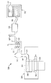
본원 발명은 유리 리본을 생산하기 위한 시스템 및 장치에 대한 것이다. 본 발명의 실시예는 도 1-2를 참고하여 설명될 것이며, 이는 유리 리본을 생산하기 위한 예시의 유리 제조 공정에 사용되기 적합한 예시의 성형 바디, 예컨대, 아이소파이프(isopipe)를 나타낸다. 도 1을 참고하여, 융합 인발 공정과 같은, 유리 제조 공정 중, 용융된 유리는 성형 바디(100)로 도입될 수 있으며, 상기 성형 바디(100)는 유입 파이프(101)를 매게로하는 트로프(103, trough)를 포함한다. 물론, 본원에 첨부된 청구범위는 융합 인발 공정에 한정되지 않아야 하며, 이는 청구된 발명이 슬롯 인발, 플롯(float), 재인발, 및 다른 공정을 포함하는 연속하는 유리 리본을 가진 임의의 유리 제조 공정에 채용될 수 있게 때문이다. 트로프(103)가 완전히 채워지면, 용융된 유리는 유리 리본(111)을 형성하기 위해 루트(109, root)에서 함께 융합되기 전 트로프의 측면을 너머 흘러넘치고 두 개의 마주하는 성형 표면(107) 아래로 흘러넘칠 수 있다. 유리 리본은 이후 예컨대, 롤러 조립체(미도시)를 이용하여 방향(113)으로 아래로 인발되고 유리 시트를 형성하기 위해 추가 처리될 수 있다. 성형 바디 조립체는 마감 캡(105) 및/또는 가장자리 디렉터(미도시, directors)와 같은 보조 요소를 추가로 포함할 수 있다.The present invention is directed to a system and apparatus for producing glass ribbon. An embodiment of the present invention will be described with reference to Figs. 1-2, which illustrate exemplary molded bodies, such as isopipes, suitable for use in exemplary glass manufacturing processes for producing glass ribbons. 1, molten glass may be introduced into the
도 2는 도 1의 성형 바디의 단면도를 나타내며, 여기에서, 성형 바디(100)는 상부 트로프 형태의 부분(102)과 하부의 웨지 형태의 부분(104)을 포함할 수 있다. 상부 트로프형 부분(102)은 용융된 유리를 수용하도록 구성된 채널(channel) 또는 트로프(103)를 포함할 수 있다. 트로프(103)는 내부 표면(121a, 121b)을 포함하는 두 개의 트로프 벽(또는 위어(weir))(125a, 125b)과, 트로프 바닥(123)으로 정의될 수 있다. 트로프가 내부 표면이 트로프 바닥과 거의 90도 각도를 형성하는 사각형 단면을 가진것으로 도시되지만, 다른 트로프 단면도 가능하며, 더불어 트로프의 내부 표면과 바닥 사이에 다른 각도를 가진 것도 가능하다. 상기 위어(125a, 125b)는 웨지 외부 표면(129a, 129b)과 함께, 두 개의 대향하는 성형 표면(107)으로 이루어질 수 있는 외부 표면(127a, 127b)을 추가로 포함할 수 있다. 용융된 유리는 위어(125a, 125b) 너머로 그리고 성형 표면(107) 아래로 흐를 수 있으며, 이후 루트(109)에서 함께 융합되어 균일한 유리 리본(111)을 형성할 수 있는 두 개의 유리 리본을 형성한다. 리본은 이때 방향 (113)으로 아래로 인발될 수 있으며, 일부 실시예에서, 유리 시트를 형성하기 위해 추가 가공될 수 있다. Figure 2 shows a cross-sectional view of the forming body of Figure 1, wherein the forming
성형 바디(100)는 유리 제조 공정에 사용되기 적합한 임의의 재료, 예컨대, 지르콘(zircon), 지르코니아(zirconia), 알루미나(alumina), 산화 마그네슘, 탄화 규소, 질화 규소, 산질화 규소, 제노타임(xenotime), 모나자이트(monazite), 이들의 합금, 및 이들의 조합과 같은, 내화 재료로 이루어질 수 있다. 다양한 실시예에 따라, 성형 바디는 단일 부품, 예컨대, 단일 소스(source)에서 가공된 하나의 부품으로 이루어질 수 있다. 다른 실시예에서, 성형 바디는 함께 접착되거나, 융합되거나, 부착되거나 또는 결합된 두 개 이상의 부품으로 이루어질 수 있으며, 예컨대 트로프형 부분과 웨지형 부분은 같거나 다른 재질로 이루어진 두 개의 개별 부품일 수 있다. 몇가지 예를 들면, 길이, 트로프 깊이 및 폭, 그리고 웨지 높이 및 폭을 포함하는, 성형 바디의 치수는 요구되는 응용에 따라 변할 수 있다. 특정 제조 공정 또는 시스템에 적합한 것으로서 이러한 치수를 선택하는 것은 당업자의 능력 내에 있다. The forming
도시되지는 않았지만, 예시의 성형 바디(100)는 피어 블록(pier blocks)(또는 지지부)가 장착될 수 있으며, 이는 예컨대, 성형 바디(100)의 하부 웨지형 부분(104)와 접하고 있을 수 있다. 피어 블록은 한쪽 또는 양쪽 말단부에서 성형 바디(100)에 압축 힘을 적용하는데 사용될 수 있다. 피어 시트(pier seats)(예컨대, 컷-아웃(cut-outs) 또는 리세스(recesses))는 피어 블록을 수용하기 위해 성형 바디(100)에 형성될 수 있으며, 실질적으로 사각형 또는 직사각형일 수 있으며, 피어 블록은 일부 실시예에서 상응하는 형태를 가질 수 있다. 예를 들어, 피어 블록은 피어 블록과 피어 시트 사이에 불연속적인 접촉을 생성하기 위해 경사진 모서리 또는 비스듬한 면이 형성될 수 있으며, 또는 피어 블록 및/또는 피어 시트는 또한 곡선으로 이루어질 수 있다. 피어 블록은 유리 제조 공정에서 사용되기 적합한 임의의 재질, 예컨대, 전술한 바와 같은, 지르콘(zircon), 지르코니아(zirconia), 알루미나(alumina), 산화 마그네슘, 탄화 규소, 질화 규소, 산질화 규소, 제노타임(xenotime), 모나자이트(monazite), 이들의 합금, 및 이들의 조합과 같은, 내화 재료로 이루어질 수 있다. 다른 실시예에서, 피어 블록은 각각의 인접한 성형 바디에 사용된 것들과 다른 재질로 이루어질 수 있다.Although not shown, the exemplary forming
본 발명의 실시예는 또한 도 3을 참고로 설명되며, 유리 리본(304)을 생산하기 위한 예시의 유리 제조 시스템(300)을 도시하고 있다. 다시, 도 3이 융합 인발 공정을 나타내고 있지만, 본원에 첨부된 청구범위는 이에 한정되지 않아야 하며, 이는 청구된 주제가 슬롯 인발, 플롯(float), 재인발, 및 다른 공정을 포함하는 연속 유리 리본을 가진 임의의 유리 제조 공정에 채용될 수 있기 때문이다. 유리 제조 시스템(300)은 용융 용기(310), 용융-청징 관(315), 청징 용기(예, 청징 튜브)(320), 청징-교반 챔버 연결 관(325)(거기에서 연장되는 평평한 관찰 스탠드 관(327)을 가진), 교반 챔버(예, 혼합 용기)(330), 교반 챔버-보울(bowl) 연결관(335), 보울(예, 이송 용기)(340), 강하관(345, downcomer), 및 유입구(355), 성형 바디(예, 아이소파이프)(360), 및 풀 롤(pull roll) 조립체(365)를 포함할 수 있는 융합 인발 기계(FDM)(350)를 포함할 수 있다.An embodiment of the present invention is also described with reference to FIG. 3 and illustrates an exemplary
유리 배치 재료(glass batch materials)는 화살표(312)로 나타낸 것처럼, 용융 용기(310)으로 도입되어 용융 유리(314)로 형성될 수 있다. 청징 용기(320)는 용융-청징 관(315)을 통해 용융 용기(310)와 연결된다. 청징 용기(320)는 용융 용기(310)로부터 용융된 유리를 수용하고 용융된 유리로부터 기포를 제거할 수 있는 고온 처리 영역을 가질 수 있다. 청징 용기(320)는 청징-교반 챔버 연결관(325)를 통해 교반 챔버(330)에 연결된다. 교반 챔버(330)는 교반 챔버-보울 연결관(335)을 통해 보울(340)에 연결된다. 보울(340)은 하향관(345)을 통과하여 FDM(350)으로 용융된 유리를 이송할 수 있다.The glass batch materials may be introduced into the
"배치 재료(batch materials)"라는 용어와 이것의 변형은 본원에서 용융 시, 반응하거나 및/또는 결합하여 유리를 형성하는 유리 전구(前驅) 성분의 혼합물을 나타낸다. 유리 배치 재료는 유리 전구 재료(precursor material)를 결합하기 위한 임의의 공지된 방법에 의해 준비되거나 및/또는 혼합될 수 있다. 예를 들어, 어떤 비-제한적인 실시예에서, 유리 배치 재료는 예컨대, 어떤 용액 또는 액체 없이 유리 전구 입자의 건조된 또는 실질적으로 건조된 혼합물을 포함할 수 있다. 다른 실시예에서, 유리 배치 재료는 슬러리 형태일 수 있으며, 예컨대, 액체 또는 용액이 존재하는 유리 전구 입자의 혼합물일 수 있다. 다양한 실시예에 따라, 배치 재료는 이산화규소, 알루미나, 및 붕소, 마그네슘, 칼슘, 소듐, 스트론튬(strontium), 주석, 또는 티타늄 산화물과 같은 다양한 첨가 산화물과 같은 유리 전구 재료를 포함할 수 있다. 예를 들어, 유리 배치 재료는 하나 이상의 추가 산화물을 갖는 이산화규소 및/또는 알루미나의 혼합물일 수 있다. 다양한 실시예에서, 유리 배치 재료는 집합적으로 알루미나 및/또는 이산화규소의 약 45에서 약 95 중량% 및 집합적으로 붕소, 마그네슘, 칼슘, 소듐, 스트론듐, 주석, 및/또는 티타늄 산화물의 적어도 하나의 약 5에서 약 55 중량%을 포함할 수 있다. 배치 재료는, 도 3을 참고로 본원에 설명된 방법을 포함하는, 당업계에 공지된 임의의 방법에 따라 용융될 수 있다. 예를 들어, 배치 재료는 용융 용기에 추가되고, 약 1100℃에서 약 1700℃, 예컨대, 모든 범위와 그 사이의 하위범위를 포함하여, 약 1300℃에서 약 1550℃, 약 1350℃에서 약 1500℃, 또는 약 1400℃에서 약 1450℃ 범위의 온도로 가열될 수 있다. 배치 재료는 어떤 실시예에서, 다양한 변수에 따라, 예컨대, 작동 온도 및 배치 크기에 따라, 수 분에서 수 시간 범위의 용융 용기에서의 체류 시간을 가질 수 있다. 예를 들어, 체류 시간은, 모든 범위와 그 사이의 하위 범위를 포함하여, 약 30분에서 약 8시간, 약 1시간에서 약 6시간, 약 2시간에서 약 5시간, 또는 약 3시간에서 약 4시간 범위일 수 있다. The term " batch materials "and variants thereof denote mixtures of glass precursor components herein which upon melting, react and / or combine to form a glass. The glass batch material may be prepared and / or mixed by any known method for joining glass precursor materials. For example, in some non-limiting embodiments, the glass batch material may comprise a dried or substantially dried mixture of glass precursor particles, for example, without any solution or liquid. In other embodiments, the glass batch material may be in the form of a slurry, for example, a mixture of glass precursor particles in which a liquid or solution is present. According to various embodiments, the batch material may include glass precursor materials such as silicon dioxide, alumina, and various additive oxides such as boron, magnesium, calcium, sodium, strontium, tin, or titanium oxide. For example, the glass batch material may be a mixture of silicon dioxide and / or alumina having one or more additional oxides. In various embodiments, the glass batch material collectively comprises from about 45 to about 95% by weight of alumina and / or silicon dioxide and collectively at least one of boron, magnesium, calcium, sodium, strontium, tin, and / From about 5 to about 55 weight percent of at least one. The batch material may be melted according to any method known in the art, including the methods described herein with reference to FIG. For example, the batch material may be added to the melt vessel and heated at about 1100 DEG C to about 1700 DEG C, such as about 1300 DEG C to about 1550 DEG C, including all ranges and subranges therebetween, to about 1500 DEG C , Or from about 1400 ° C to about 1450 ° C. The batch material may, in certain embodiments, have a residence time in the melting vessel ranging from several minutes to several hours, depending on various variables, e.g., depending on the operating temperature and batch size. For example, the residence time can range from about 30 minutes to about 8 hours, from about 1 hour to about 6 hours, from about 2 hours to about 5 hours, or from about 3 hours to about 3 hours, including all ranges and subranges therebetween It can be 4 hours range.
계속해서 도 3을 참고하여, FDM(350)은 유입구(355), 성형 바디(360), 및 풀롤 조립체(365, pull roll assembly)를 포함할 수 있다. 유입구(355)는 하향관(345)으로부터 용융된 유리를 수용할 수 있으며, 그로부터 성형 바디(360)로 흐를 수 있고, 이는 유리 리본(304)으로 형성된다. 풀롤 조립체(365)는 추가 선택 장치에 의해 추가 처리를 위해 인발된 유리 리본(304)을 이송할 수 있다. 예를 들어, 유리 리본은 유리 리본을 스코어링하기 위한 기계 스코어링 장치(scoring device)를 포함할 수 있는 이송 앤빌 기계(TAM, traveling anvil machine)에 의해 추가 처리될 수 있으며, 또는 유리 리본을 스코어링하거나 또는 유사하게 자르기 위해 레이저 기계장치에 의해 처리된다. 스코어링된 유리는 이후 당업계에 공지된 다양한 방법과 장치를 이용하여, 유리 시트의 조각으로 분리되고, 가공, 폴리싱(polishing), 화학적 강화, 및/또는 예컨대, 에칭(etching)과 같은 표면 처리될 수 있다. 통상적으로, 가장자리 부분 또는 비드는 유리 시트에서 분리되어 다음으로 유리 제조 시스템의 마무리 라인 또는 부분(미도시)의 TAM에 의한 처리된다. 상기 가장자리 부분 또는 비드를 분리하는 종래의 수단은 당업계에 공지된 레이저 분리 및/또는 기계적 스코어링 방법 및 장치를 포함한다.3, the
용융된 유리는 또한 예컨대, 기포 제거를 위한 청징 단계와, 용융 유리를 균질화하기 위한 교반 단계를 포함하는 다양한 추가 공정 단계를 겪을 수 있다. 용융된 유리는 이후 원에 게시된 성형 바디를 이용하여 유리 리본을 생산하도록 처리될 수 있다. 예를 들어, 전술한 것처럼, 용융된 유리는 하나 이상의 유입구를 통해 이송 말단부에서 성형 바디의 트로프형 부분으로 도입될 수 있다. 유리는 이송 말단부에서 압축 말단부로 진행 방향으로 흐를 수 있으며, 두 개의 트로프 벽을 너머서, 웨지형 부분의 두 개의 대향하는 외부 표면 아래로 흘러, 단일 유리 리본을 형성하도록 루트에서 수렴된다.The molten glass may also undergo various further processing steps including, for example, a clarification step for bubble removal and a stirring step for homogenizing the molten glass. The molten glass can then be processed to produce a glass ribbon using the molded body posted in the circle. For example, as discussed above, the molten glass may be introduced into the trough-shaped portion of the forming body at the transferring end through one or more inlets. The glass can flow in the direction from the transfer end to the compression end and over the two trough walls, flows under the two opposite outer surfaces of the wedge-shaped portion and converges at the root to form a single glass ribbon.
비-제한적인 예시로서, 성형 바디 장치는, 또한, 모든 범위와 그 하위 범위를 포함하여, 가장 고온 지점에서(예, 트로프형 부분 근처의 상부 "머플(muffle)" 지역에서), 약 1100℃ 에서 약 1350℃, 약 1150℃ 에서 약 1325℃, 약 1150℃ 에서 약 1300℃, 약 1175℃ 에서 약 1250℃, 또는 약 1200℃ 에서 약 1225℃의 온도 범위에서 작동하는 용기에 둘러싸일 수 있다. 그 가장 낮은 온도 지점에서(예, 성형 바디의 루트 근처 하부의 "전이" 지역에서), 용기는, 모든 범위와 그 하위 범위를 포함하여, 약 800℃ 에서 약 1250℃, 약 850℃ 에서 약 1225℃, 약 900℃ 에서 약 1200℃, 약 950℃ 에서 약 1150℃, 또는 약 1000° 에서 약 1100℃, 온도 범위에서 작동할 수 있다. As a non-limiting example, a shaped body device may also be formed at a highest temperature point (e.g., in the upper "muffle" region near the trough shaped portion) About 1350 ° C, about 1350 ° C to about 1325 ° C, about 1150 ° C to about 1300 ° C, about 1175 ° C to about 1250 ° C, or about 1200 ° C to about 1225 ° C. At its lowest temperature point (e. G., In the "transition" region below the roots of the molded body), the vessel is heated to about 1250 DEG C at about 800 DEG C, about 1225 DEG C at about 850 DEG C, About 900 ° C to about 1200 ° C, about 950 ° C to about 1150 ° C, or about 1000 ° to about 1100 ° C.
도 3을 참고하여, 본원에 설명된 예시의 실시예는, 기계 스코어링 기계장치 또는 레이저 기계장치에 의해 수평 분리된 후 유리 시트의 비드 또는 가장자리 부분을 분리하는 것 대신, TAM, 레이저 절단 기계장치, 또는 다른 적합한 절단 기계장치로 절단하기 전에 FDM(350)의 유리 리본(304)의 어떤 적합한 위치에서 유리 리본의 균열을 개시하고, 위치를 탐지하거나 멈출 수 있다. 상기 "개시한다"는 용어가 시작하게 하거나 및/또는 한정하게 한다는 것을 의미한다는 것을 알야야 한다. 예를 들어, 일부 실시예에서, 균열은 유리 리본에서 개시되거나 또는 시작하게 하거나 및/또는 한정될 수 있다. 예를 들어, 도 4는 본 발명의 일부 실시예의 측면 모습이다. 도 4를 참고하여, 용융된 유리는 예시의 성형 바디(360)로 공급될 수 있으며, 상기 용융된 유리는 성형 바디의 벽을 흘러넘쳐서 두 개의 개별 흐름의 용융된 유리로 분리되며, 수렴 성형 표면 위로 흘러 성형 바디(360)의 루트(301)로 흐른다. 용융된 유리의 분리 유동이 성형 바디(360)의 루트(301)에 도달하면, 이들은 성형 바디(360)의 루트로부터 하강하는 유리 리본(304)을 형성하기 위해 재결합한다. 가장자리 디렉터(306)는 루트(301)의 폭을 확장하기 위해 성형 바디(360)에 배치될 수 있으며, 이로써 유리 리본(304)을 쉽게 넓게하거나, 최소한으로, 유리 리본(304)이 좁아지는 것을 최소화하도록 작동한다. 작동 시, 통상적으로 4개의 가장자리 디렉터(306)가 있으며, 두 개의 가장자리 디렉터는 성형 바디의 일측 단부에서 서로 대향하며 나머지 대향하는 둘은 성형 바디의 반대 말단에 배치된다; 그러나, 도 4는 하나의 예시의 성형 바디(360)의 사시도로서, 가장자리 디렉터 중 두개는 보이지 않는다.3, embodiments of the exemplary embodiments described herein may be applied to a TAM, a laser cutting machine, or a laser cutting machine, instead of separating the bead or edge portion of the glass sheet after horizontally separated by a machine scoring machine or a laser machine. Start or stop the cracking of the glass ribbon at any suitable position of the
유리 리본(304)이 루트로부터 하강하기 때문에, 풀링 롤(365, pulling rolls)은 그 가장자리를 따라 점도가 있는 유리 리본과 접촉하며 하향 경로로의 리본의 인발을 돕는다. 풀링 롤(365)은 유리 리본의 가장자리 부분에서 유리 리본(304)을 파지하고 유리 리본을 하향으로 인발하는, 대향하는 역회전 롤러(counter-rotating roller)를 포함한다. 도시되진 않지만, 풀링 롤(365) 위에 및/또는 아래에 배치된 추가 구동되는 또는 비-구동되는 롤이 또한 유리 리본의 가장자리에 접촉하여 리본을 가이드하고, 리본의 폭을 줄이도록 자연히 일어나는 표면 장력 효과에 대해 리본의 폭을 유지하는 것을 도울 수 있다. 또한, 임의의 수의 도시된 및/또는 추가로 구동되는 또는 비-구동되는 롤은 수평에 대해 경사지거나 기울어질 수 있다. Because the
다수의 냉각 또는 가열 노즐, 버너, 레이저, IR 가열기 또는 제트(370a~h)는 예시의 FDM(350) 내에 배치될 수 있으며, 각각은 냉각 가스 또는 가열 가스를 공급할 수 있다. 이에 한정하지 않지만, 상기 가스는 공기, 질소, 수소, 불활성 가스, 다른 가연성 가스, 이들의 혼합 등을 포함한다. 물론, 가열 노즐, 버너 또는 제트는 오직 예시이며 청구 범위는 이에 한정되어선 안되며 다양한 다른 기계장치가 사용될 수 있다. 예를 들어, 일부 실시예에서, 레이저, IR 가열기 등과 동일한 목적을 가진 가열 장치 또는 기계장치가 채용될 수 있다. 추가 실시예에서, 공급된 가스는 각각의 가열 노즐, 버너 또는 제트(370a~h)로 이송되기 전에 냉각, 혼합 및/또는 가열될 수 있다. 예시의 실시예에서, 다수의 가열 또는 냉각 노즐(370a~h)은 가열 또는 냉각된 공기를 연속으로 이동하는 유리 리본(304)의 특정 부분에서 리본의 미리 정해진 부분, 선 또는 영역(305)을 따라 지향되도록 구성될 수 있다. 일반적으로, 유리 리본의 이러한 미리정해진 부분(305)의 수직 분리(예, 유동 방향으로의 분리)는 불필요한 비드를 포함하는 유리 리본의 최외곽 부분 또는 가장자리(306)를 필수적으로 제거할 것이다. 일부 실시예에서, 예시의 가열 또는 냉각 노즐, 제트 또는 버너(370a~h)는 가연성 혼합물을 제공하여 인접한 유동하는 유리 리본으로 화염을 제공할 수 있다. 도 5는 예시의 노즐 기계장치의 일부 실시예의 사시도이다. 도 5를 참고하여, 예시의 노즐, 제트 또는 버너(370)는 인근 말단부(372)에 하나 이상의 유입구 또는 공급 라인(371)을 구비할 수 있으며, 상기 인근 말단부(372)는 인접한 유동하는 유리 리본(미도시)으로 화염, 가열된 공기, 냉각된 공기, 가열된 또는 냉각된 공기의 제트 등을 공급하기 위해 하나 이상의 가스를 노즐, 제트 또는 버너(370)로 그리고 말단부(374)의 하나 또는 다수의 노즐, 구멍 또는 제트(373)로 하나 이상의 가스를 공급한다. 물론, 다양한 가스 전달 장치가 출원인의 유리 제조 시스템에 연속하는 유리 리본의 균열을 개시하고 위치를 탐지하거나 멈추도록 채용될 수 있을 것이 예상되므로, 도 5에 도시된 실시예는 본원에 첨부된 청구 범위에 한정하지 않아야 한다. 공급된 가스는, 그 사이의 모든 하위 범위를 포함하여, 약 20℃ 에서 약 1700℃, 약 500℃ 에서 약 1700℃, 약 700℃ 에서 약 1700℃, 약 750℃ 에서 약 850℃, 약 850℃ 에서 약 1450℃, 약 1450℃ 에서 약 1700℃의 범위의 온도로 제공될 수 있다. 공급된(가열된 또는 냉각된) 가스는 또한 모든 범위 및 그 사이의 하위 범위를 포함하여, 약 +/- 0.1℃ 에서 약900℃ 사이의 온도차(이상 또는 이하)로 연속 유리 리본에 제공될 수 있다. 상기 온도와 온도차는 예시의 실시예에 의해 채용되어 유리 리본의 압축 또는 인장 응력을, 모든 하위 범위들을 포함하여, 약 0.1MPa에서 약 50MPa 이상 사이, 약 1MPa에서 약 25MPa, 또는 약 5MPa에서 20MPa 사이에서 변경할 수 있다. 도 4에 도시된 것처럼, 예시의 노즐, 버너 또는 제트(370a~h)는 유리 리본(304)의 가장자리의 안쪽으로 성형 바디(360)의 루트(301)에 또는 루트 근처에 배치될 수 있다(예, 유리 리본의 가장자리와 중앙선 사이). 일부 실시예에서, 균열 개시 노즐, 버너 또는 제트(370a~h)는 루트의 하류에 약 2500mm에서 7500mm 사이에 위치될 수 있다. 일부 실시예에서, 위치는 그 사이의 모든 하위 범위를 포함하여, 루트의 하류에 약 1000 mm 에서 약 8000 mm 사이, 약 2000 mm 에서 약 7000 mm, 약 3000 mm 에서 약 6000 mm, 또는 약 4000 mm 에서 약 5000 mm 사이에 있을 수 있다. 다른 실시예에서, 균열 저지 노즐 버너 또는 제트(370a~h)는 루트에 그리고 균열 개시 노즐의 상류에 약 500mm 에서 약 5500mm 사이에 위치될 수 있다. 추가 실시예에서, 위치는, 모든 하위 범위를 포함하여, 균열 개시 노즐의 상류에, 약 100 mm 에서 약 6000 mm 사이, 약 500 mm 에서 약 5500 mm 사이, 약 1000 mm 에서 약 5000 mm 사이, 또는 약 2000 mm 에서 약 4000 mm 사이에 있을 수 있다. 예시의 노즐, 버너 또는 제트(370a~h)는 수평 기계의 또는 레이저 스코어링/절단 기계장치와 같은 하류의 절단 기계장치(미도시)와 루트(301) 사이에서 유리 리본을 따라 임의의 장소에 배치될 수 있다. 다른 실시예에서, 예시의 노즐, 버너 또는 제트 또는 상기 장치(309)의 배열은 본원에 명시된 동일한 원리를 이용하여 하류 절단 기계장치를 대체하기 위해 유리 유동 방향에 수평으로 또는 수직으로 배치될 수 있다. 노즐, 버너 또는 제트(370, 309)에 의해 방출된 가스는 유리 리본에 영향을 주며 유리의 점도를 국부적으로 변형시켜 부분적으로 얇아지게 하거나 및/또는 압축 응력의 변화를 야기할 수 있다. 예시의 노즐, 버너, 또는 제트(370, 309)가 리본 상의 상대적인 위치를 변화시키고 잘려나갈 리본의 양 또는 절단 위치를 변화시키기 위해 고정되는 대신 움직일 수 있다는 것을 알 수 있다. 도시되진 않았지만, 추가 기계장치들(기계적인 또는 다른)은 임의의 리본 가장자리 손상을 막고 하류 작업으로 인한 비드의 움직임을 막도록 유리 리본에 의해 형성된 평면의 외측의 분리된 비드를 대체하기 위해 예시의 가열 및 냉각 기계장치(370a~h)의 하류에 채용될 수 있다. A number of cooling or heating nozzles, burners, lasers, IR heaters, or
물론, 도면은 단지 예시적인 것이어야 하며 예시의 가열기 및 냉각기(더불어 다른 기계장치들)로서 청구범위를 한정하지 않아야 하며, 그 위치는 유리 리본의 균열을 개시, 전파하고 그리고 멈추거나 위치를 탐지하기 위해 실시예에서 사용될 수 있다. 예를 들어, 일부 실시예에서, 한 세트의 가열 기계장치(370a,e)는 루트에 가까운 상부 경계와 루트 아래의 약 25mm에서 100mm의 하부 경계를 가진 것으로 제공될 수 있다. 일부 실시예에서, 루트에 대한 예시의 위치가 에너지를 유리의 표면에서 전체 두께로 전달할 수 있으며 유리를 효과적으로 얇게 하는데 사용될 수 있음을 몇몇 실험이 나타내고 있기 때문에, 상기 상부 경계는 루트보다 약 100mm 위에 있을 수 있다. 이러한 가열 기계장치는 유리의 용융 온도(Tglass) 이상의 온도로 제공되어 유리 리본의 점도을 낮추고 선택된 부분에서 유리 리본을 얇게 한다. 또한, 점탄성 구역 아래로 저 진폭 잔류 압축 응력을 유도하며 균열 전파를 수직으로 유도 또는 제어할 수 있으며 균열을 제한할 수 있는 유리 리본의 얇은 레인(thin lane)을 생성하도록 이러한 가열 기계장치는 채용될 수 있다. 이러한 예시의 가열 기계장치는 일반적으로 예시의 유리 제조 시스템의 작동 중 항상 작동되어야 한다. 상기 가열 기계장치는 일반적으로 얇게 만들기 위해 채용될 수 있으며, 가스를 사용하는 경우, 가스 온도는 약 150,000 poise의 유동 점도에서 유리 온도보다 적어도 100℃ 이상에서 적어도 200℃ 이상이어야 하며, 또는 약 140,000poise의 점도를 가진 유리에 대해, 온도 범위는 약 1040℃에서 1240℃이어야 한다. 제1 세트의 냉각 기계장치(370b,f)는 상부 세팅 구역 경계로부터 상류에 약 300mm 또는 가열 기계장치(370a,e)로부터 하류에 약 200mm의 상부 경계를 구비하며, 어느 쪽이든지 더 하류에 있으며, 구역이 시작되는 곳으로부터 하류에 약 300mm에 하부 경계를 구비할 수 있다. 일반적으로, 세팅 구역의 위치는 리본 냉각 속도에 따른다. 상기 제1 세트의 냉각 기계장치(370b,f)는 유리의 용융온도(Tglass) 이하의 온도로 제공되어 냉각된 레인을 생성하고 유도된 응력의 진폭을 증가시킨다. 상기 제1 세트의 냉각 기계장치(370b,f)는 기계장치(370a,e)로부터 얇은 또는 냉각된 레인과 정렬된다. 또한, 균열 개시를 위해 FDM의 출구에서 응력(압축 또는 인장) 밴드(band)를 유지하고 균열의 상류 전파를 허용하는 것이 바람직할 수 있다. 이러한 예시의 제1 냉각 기계장치는 일반적으로 균열 개시 전에 작동해야 하며 이후 필요시 작동이 유지될 수 있다. 일반적으로, 유리 전이 온도는 약 630℃에서 약 830℃의 온도 범위이다. 세팅 구역은 일반적으로 유리 전이 온도에서 약 +/- 65℃이며, 이로써, 제1 세트의 냉각 기계장치로부터의 가스의 온도는 유리 온도보다 100℃ 이하이어야 하며, 이는 제1 세트의 냉각 기계장치에서 약 650℃에서 약 950℃이다. 제2 세트의 냉각 기계장치(370c,g)는 이때 냉각된 레인과 정렬될 수 있으며 유리 전이 온도의 위치에서의 상부 경계와 유리 전이 온도로부터 하류의 임의의 하부 경계를 구비할 수 있다(예, 하향 인발 융합 성형에 대해, 이러한 위치는 하류 세팅 구역 경계의 +/- 100mm 일 수 있다). 상기 제2 세트의 냉각 기계장치(370c,g)는 유리의 용융온도(Tglass) 이하의 온도로 제공되어 유도된 응력을 다룰수 있으며 한정된 위치에서 균열을 멈추는데 사용될 수 있다. 이러한 예시의 제2 냉각 기계장치는 일반적으로 예시의 유리 제조 시스템의 작동 중 항상 작동되어야 한다. 추가 기계장치(기계적인 또는 다른)는 예시의 가열 및 냉각 기계장치(370)의 하류에 채용되어 하류 작동으로 인한 비드의 움직임을 막고 임의의 리본 가장자리 손상을 막기 위해 유리 리본에 의해 형성된 평면의 외측의 분리된 비드를 대체할 수 있다. 이러한 추가 기계장치는 균열 개시 이후 활성화되어야 하며 이후 항상 작동을 유지해야하고, 일부 실시예에서는 제2 세트의 냉각 기계장치의 하류에 약 500mm 에서 1000mm 에 배치될 수 있다.Of course, the drawings should be illustrative only and should not limit the claims as examples of heaters and coolers (as well as other mechanical devices), the location of which may include initiating, propagating, stopping, May be used in the embodiment. For example, in some embodiments, a set of
추가 실시예에서, 일부 실시예에서, 제1 세트의 가열 기계장치(370a,e)는 루트에 가까운 상부 경계와 루트 아래에 약 25mm 에서 약 100mm 에 하부 경계를 포함할 수 있다. 일부 실시예에서, 루트에 대한 예시의 위치가 에너지를 유리의 표면에서 전체 두께로 전달할 수 있으며 유리를 효과적으로 얇게 하는데 사용될 수 있음을 몇몇 실험이 나타내고 있기 때문에, 상기 상부 경계는 루트보다 약 100mm 위에 있을 수 있다. 이러한 제1 세트의 가열 기계장치는 유리의 용융 온도(Tglass) 이상의 온도로 제공되어 유리 리본의 점도을 낮추고 선택된 부분에서 유리 리본을 얇게 한다. 또한, 점탄성 구역 아래로 저 진폭 잔류 압축 응력을 유도하며 균열 전파를 수직으로 유도 또는 제어할 수 있으며 균열을 제한할 수 있는 유리 리본의 얇은 레인을 생성하도록 이러한 제1 세트의 가열 기계장치는 채용될 수 있다. 이러한 예시의 가열 기계장치는 일반적으로 예시의 유리 제조 시스템의 작동 중 항상 작동되어야 한다. 상기 가열 기계장치는 일반적으로 얇게 만들기 위해 채용될 수 있으며, 가스를 사용하는 경우, 가스 온도는 약 150,000 poise의 유동 점도에서 유리 온도보다 적어도 100℃ 이상에서 적어도 200℃ 이상이어야 하며, 또는 약 140,000poise의 점도를 가진 유리에 대해, 온도 범위는 약 1040℃에서 1240℃이어야 한다. 제1 세트의 냉각 기계장치(370b,f)는 상부 세팅 구역 경계로부터 상류에 약 300mm 또는 가열 기계장치(370a,e)로부터 하류에 약 200mm의 상부 경계를 구비하며, 어느 쪽이든지 더 하류에 있으며, 구역이 시작되는 곳으로부터 하류에 약 300mm의 하부 경계를 구비할 수 있다. 일반적으로, 세팅 구역의 위치는 리본 냉각 속도에 의존한다. 상기 제1 세트의 냉각 기계장치(370b,f)는 유리의 용융온도(Tglass) 이하의 온도로 제공되어 냉각된 레인을 생성하고 유도된 응력의 진폭을 증가시킨다. 상기 제1 세트의 냉각 기계장치(370b,f)는 기계장치(370a,e)로부터 얇은 또는 냉각된 레인과 정렬된다. 또한, 균열 개시를 위해 FDM의 출구에서 응력(압축 또는 인장) 밴드(band)를 유지하고 균열의 상류 전파를 허용하는 것이 바람직할 수 있다. 이러한 예시의 제1 냉각 기계장치는 일반적으로 균열 개시 전에 작동해야 하며 이후 필요시 작동이 유지될 수 있다. 일반적으로, 유리 전이 온도는 약 630℃에서 약 830℃의 온도 범위이다. 세팅 구역은 일반적으로 유리 전이 온도에서 약 +/- 65℃이며, 이로써, 냉각 기계장치 세트로부터의 가스의 온도는 유리 온도보다 100℃ 이하이어야 하며, 이는 제1 세트의 냉각 기계장치에서 약 650℃에서 약 950℃이다. 제2 세트의 냉각 기계장치(370c,g)는 이때 냉각된 레인과 정렬될 수 있으며 유리 전이 온도의 위치에서의 상부 경계와 유리 전이 온도로부터 하류의 임의의 하부 경계를 구비할 수 있다(예, 하향 인발 융합 성형에 대해, 이러한 위치는 하류 세팅 구역 경계의 +/- 100mm 일 수 있다). 상기 제2 세트의 냉각 기계장치(370c,g)는 유리의 용융온도(Tglass) 이상의 온도(예, 100℃ 이상)로 제공되어 유도된 응력을 다룰수 있으며 한정된 위치에서 균열을 멈추는데 사용될 수 있다. 이러한 예시의 제2 가열 기계장치는 일반적으로 균열 개시 바로 전에 활성화되어야 하며 예시의 유리 제조 시스템의 작동 중 항상 작동을 유지하여야 한다. 추가 기계장치(기계적인 또는 다른)는 예시의 가열 및 냉각 기계장치(370)의 하류에 채용되어 하류 작동으로 인한 비드의 동작을 막고 임의의 리본 가장자리 손상을 막기 위해 유리 리본에 의해 형성된 평면의 외측의 분리된 비드를 대체할 수 있다. 이러한 추가 기계장치는 균열 개시 이후 활성화되어야 하며 이후 항상 작동을 유지해야하고, 일부 실시예에서는 제2 세트의 냉각 기계장치의 하류에 약 500mm 에서 1000mm 에 배치될 수 있다.In a further embodiment, in some embodiments, the first set of
추가 실시예에서, 제1 세트의 가열 기계장치(370a,e)는 루트에 가까운 상부 경계와 루트 아래에 약 25mm 에서 약 100mm 에 하부 경계를 포함할 수 있다. 일부 실시예에서, 루트에 대한 예시의 위치가 에너지를 유리의 표면에서 전체 두께로 전달할 수 있으며 유리를 효과적으로 얇게 하는데 사용될 수 있음을 몇몇 실험이 나타내고 있기 때문에, 상기 상부 경계는 루트보다 약 100mm 위에 있을 수 있다. 이러한 제1 세트의 가열 기계장치는 유리의 용융 온도(Tglass) 이상의 온도로 제공되어 유리 리본의 점도을 낮추고 선택된 부분에서 유리 리본을 얇게 한다. 또한, 점탄성 구역 아래로 저 진폭 잔류 압축 응력을 유도하며 균열 전파를 수직으로 유도 또는 제어할 수 있으며 균열을 제한할 수 있는 유리 리본의 얇은 레인을 생성하도록 이러한 제1 세트의 가열 기계장치는 채용될 수 있다. 이러한 예시의 가열 기계장치는 일반적으로 예시의 유리 제조 시스템의 작동 중 항상 작동되어야 한다. 상기 가열 기계장치는 일반적으로 얇게 만들기 위해 채용될 수 있으며, 가스를 사용하는 경우, 가스 온도는 약 150,000 poise의 유동 점도에서 유리 온도보다 적어도 100℃ 이상에서 적어도 200℃ 이상이어야 하며, 또는 약 140,000poise의 점도를 가진 유리에 대해, 온도 범위는 약 1040℃에서 1240℃이어야 한다. 한 세트의 냉각 기계장치(370b,f)는 상부 세팅 구역 경계로부터 상류에 약 300mm 또는 가열 기계장치(370a,e)로부터 하류에 약 200mm의 상부 경계를 구비하며, 어느 쪽이든지 더 하류에 있으며 구역이 시작되는 곳으로부터 하류에 약 300mm의 하부 경계를 구비할 수 있다. 일반적으로, 세팅 구역의 위치는 리본 냉각 속도에 따른다. 이러한 세트의 냉각 기계장치(370b,f)는 유리의 용융온도(Tglass) 이하의 온도로 제공되어 냉각된 레인을 생성하고 유도된 응력의 진폭을 증가시킨다. 또한, 균열 개시를 위해 FDM의 출구에서 응력(압축 또는 인장) 밴드를 유지하고 균열의 상류 전파를 허용하는 것이 바람직할 수 있다. 이러한 예시의 냉각 기계장치는 일반적으로 균열 개시 전에 작동해야 하며 이후 필요시 작동이 유지될 수 있다. 일반적으로, 유리 전이 온도는 약 630℃에서 약 830℃의 온도 범위이다. 세팅 구역은 일반적으로 유리 전이 온도에서 약 +/- 65℃이며, 이로써, 냉각 기계장치 세트로부터의 가스의 온도는 유리 온도보다 100℃ 이하이어야 하며, 이는 세트의 냉각 기계장치에서 약 650℃에서 약 950℃이다. 추가 기계장치(기계적인 또는 다른)는 예시의 가열 및 냉각 기계장치(370)의 하류에 채용되어 하류 작동으로 인한 비드의 동작을 막고 임의의 리본 가장자리 손상을 막기 위해 유리 리본에 의해 형성된 평면의 외측의 분리된 비드를 대체할 수 있다. 이러한 추가 기계장치는 균열 개시 이후 활성화되어야 하며 이후 항상 작동을 유지해야하고, 일부 실시예에서는 제2 세트의 냉각 기계장치의 하류에 약 500mm 에서 1000mm 에 배치될 수 있다.In a further embodiment, the first set of
일부 실시예에서, 어떤 가열 기계장치도 사용되지 않는다; 그러나, 제1 세트의 냉각 기계장치(370b,f)는 상부 세팅 구역 경계로부터 상류에 약 300mm 또는 구역이 시작되는 곳으로부터 하류 약 300mm의 상부 경계를 구비한다. 일반적으로 세팅 구역의 위치는 리본 냉각 속도에 따른다. 이러한 제1 세트의 냉각 기계장치(370b,f)는 유리의 용융온도(Tglass) 이하의 온도로 제공되어 냉각된 레인을 생성하고 유도된 응력의 진폭을 증가시킨다. 이러한 제1 세트의 가열 기계장치는 또한 균열 전파를 수직으로 유도하고 균열을 제한하는데 사용될 수 있다. 이러한 예시의 제1 냉각 기계장치는 예시의 유리 제조 시스템의 작동 중 항상 작동을 유지해야한다. 일반적으로, 유리 전이 온도는 약 630℃에서 약 830℃의 온도 범위이다. 세팅 구역은 일반적으로 유리 전이 온도에서 약 +/- 65℃이며, 이로써, 냉각 기계장치 세트로부터의 가스의 온도는 유리 온도보다 100℃ 이하이어야 하며, 이는 제1 세트의 냉각 기계장치에서 약 650℃에서 약 950℃이다. 제2 세트의 냉각 기계장치(370c,g)는 이때 냉각된 레인과 정렬될 수 있으며 유리 전이 온도의 위치에서 상부 경계와 유리 전이 온도로부터 하류의 임의의 하부 경계를 구비할 수 있다(예, 하향 인발 융합 성형에 대해, 이러한 위치는 하류 세팅 구역 경계의 +/- 100mm 일 수 있다). 상기 제2 세트의 냉각 기계장치(370c,g)는 유리의 용융온도(Tglass) 이하의 온도로 제공되어 유도된 응력을 다룰수 있으며 한정된 위치에서 균열을 멈추는데 사용될 수 있다. 이러한 예시의 제2 냉각 기계장치는 일반적으로 예시의 유리 제조 시스템의 작동 중 항상 작동되어야 한다. 추가 기계장치(기계적인 또는 다른)는 예시의 가열 및 냉각 기계장치(370)의 하류에 채용되어 하류 작동으로 인한 비드의 동작을 막고 임의의 리본 가장자리 손상을 막기 위해 유리 리본에 의해 형성된 평면의 외측의 분리된 비드를 대체할 수 있다. 이러한 추가 기계장치는 균열 개시 이후 활성화되어야 하며 이후 항상 작동을 유지해야하고, 일부 실시예에서는 제2 세트의 냉각 기계장치의 하류에 약 500mm 에서 1000mm 에 배치될 수 있다.In some embodiments, no heating mechanism is used; However, the first set of
또 다른 실시예에서, 한 세트의 냉각 기계장치(370b,f)는 상부 세팅 구역 경계로부터 상류 또는 구역이 시작되는 곳으로부터 하류의 약 200mm의 상부 경계를 구비한다. 일반적으로, 세팅 구역의 위치는 리본 냉각 속도에 따른다. 이러한 세트의 냉각 기계장치(370b,f)는 유리의 용융온도(Tglass) 이하의 온도로 제공되어 냉각된 레인을 생성하고 유도된 응력의 진폭을 증가시킨다. 이러한 세트의 냉각 기계장치는 또한 균열 전파를 수직으로 유도하고 균열을 제한하는데 사용될 수 있다. 이러한 예시의 제1 냉각 기계장치는 예시의 유리 제조 시스템의 작동 중 항상 작동을 유지해야한다. 일반적으로, 유리 전이 온도는 약 630℃에서 약 830℃의 온도 범위이다. 세팅 구역은 일반적으로 유리 전이 온도에서 약 +/- 65℃이며, 이로써, 냉각 기계장치 세트로부터의 가스의 온도는 유리 온도보다 100℃ 이하이어야 하며, 이는 제1 세트의 냉각 기계장치에서 약 650℃에서 약 950℃이다. 한 세트의 가열 기계장치(370c,g)는 이때 잔류 응력 레인의 양측에 배치되거나 정렬될 수 있으며 유리 전이 온도의 위치에서 상부 경계와 유리 전이 온도로부터 하류의 임의의 하부 경계를 구비할 수 있다(예, 하향 인발 융합 성형에 대해, 이러한 위치는 하류 세팅 구역 경계의 +/- 100mm 일 수 있다). 이러한 세트의 가열 기계장치(370c,g)는 유리의 용융온도(Tglass) 이상의 온도(예, 100℃ 이상)로 제공되어 유도된 응력을 다룰수 있으며 한정된 위치에서 균열을 멈추는데 사용될 수 있다. 이러한 예시의 가열 기계장치는 일반적으로 균열 개시 바로 전에 활성화되어야 하며 예시의 유리 제조 시스템의 작동 중 항상 작동을 유지하여야 한다. 추가 기계장치(기계적인 또는 다른)는 예시의 가열 및 냉각 기계장치(370)의 하류에 채용되어 하류 작동으로 인한 비드의 동작을 막고 임의의 리본 가장자리 손상을 막기 위해 유리 리본에 의해 형성된 평면의 외측의 분리된 비드를 대체할 수 있다. 이러한 추가 기계장치는 균열 개시 이후 활성화되어야 하며 이후 항상 작동을 유지해야하고, 일부 실시예에서는 제2 세트의 냉각 기계장치의 하류에 약 500mm 에서 1000mm 에 배치될 수 있다.In yet another embodiment, a set of
유리는 탄성 파괴 역학이 적용되는 취성 재료이다. 균열이 진행됨으로써 발생한 에너지가 새로운 표면 영역을 생성하는데 필요한 에너지보다 더 큰 경우 균열은 이러한 재료에서 전파된다. 이러한 개념은 응력 강도 인자 및 파괴 인성(fracture toughness)을 이용함으로써, 본원에 게시된 실시예에 채용될 수 있다. 응력 확대 계수는 재료의 탄성 특성, 형상, 및 하중으로부터 계산될 수 있으며, 균열의 선단(tip) 근처의 응력 조건으로 요약된다. 도 6은 균일한 인장 응력 σ을 받는 표본의 길이 a의 관통 균열의 개략도이다. 도 6에 도시된 상황에 대한 응력 확대 계수는 하기의 수식의 K1(응력 x 길이)으로 제공될 수 있다.Glass is a brittle material to which elastic fracture mechanics is applied. If the energy generated by the progress of the crack is greater than the energy required to create a new surface area, the crack propagates in this material. This concept can be employed in the embodiments disclosed herein by utilizing stress intensity factors and fracture toughness. The stress intensity factor can be calculated from the elastic properties, shape, and load of the material and is summarized as the stress condition near the tip of the crack. 6 is a schematic view of penetration cracks of length a of the specimen subjected to uniform tensile stress? The stress magnification factor for the situation shown in Fig. 6 can be provided by K 1 (stress x length) of the following equation.
![]()
![]()
파괴 인성, K1c는 균열에 대한 저항을 나타내는 재료 특성이다. K1이 K1c를 초과하는 경우, 균열이 전파된다. 그러나, 균열이 응력 분포를 변화시킴으로써 멈춰질 수 있으므로 K1은 K1c 이하로 떨어진다는 것이 밝혀졌다. 도 7은 표본에 대한 균열이 정지에 대한 개략도이다. 도 7에 도시된 것처럼, 점선으로 표시된 균열은 좌표계의 원점에서 끝나고, 압축 응력 레인은 다음에 의해 주어진 온도 필드에 의해 생성된다:The fracture toughness, K 1c, is a material characteristic that shows resistance to cracking. If K 1 exceeds K 1c , the crack propagates. However, it has been found that K 1 falls below K 1c because the crack can be stopped by changing the stress distribution. Figure 7 is a schematic view of a crack stop for a specimen. As shown in Fig. 7, the cracks indicated by dashed lines terminate at the origin of the coordinate system, and the compressive stress lane is generated by the temperature field given by:
![]()
![]()
여기서, ΔTmax는 레인의 최대 온도 변화를 나타내고 w는 최대값의 절반에서의 폭을 나타낸다. 용어 "레인(lane)"은 본원에서 일반적으로 유리 리본의 일부분으로서 사용된다. 이 일부분은 표면 영역일 수 있으며 또는 응력이 벌크 유리 리본의 응력과 다른 체적일 수도 있다. 이러한 온도 분포는 융합 성형 공정에서의 세팅 구역 위의 좁은 스트립(strip)을 냉각함으로써 발생된 것과 유사한 응력을 야기할 수 있다. 도 7에 도시된 구성에서 그리고 수식 (2)의 ΔT(y)에 따라, K1은 유한 요소 모델에 의해 결정될 수 있으며 하기 관계에 의해 근사된다:Here, ΔT max represents the maximum temperature change of the lane and w represents the width at half the maximum value. The term "lane" is generally used herein as part of a glass ribbon. This portion may be a surface area or the stress may be a different volume than the stress of the bulk glass ribbon. This temperature distribution can cause stresses similar to those generated by cooling narrow strips on the setting zone in the fusion forming process. According to the configuration shown in FIG. 7 and according to? T (y) in Equation (2), K 1 can be determined by a finite element model and is approximated by the following relation:

여기서 E는 유리의 영률(young's modulus)을 나타내고, α는 유리의 열팽창 계수를 나타내며, m은 1미터를 나타낸다. 수식(2)와 다른 온도 분포의 함수 형태가 결정될 수 있지만 유사한 형태이지만 다른 상수를 가진 수식(3)에서의 좌표 y 결과(ΔT(y))에 여전히 의존할 수 있다. Where E is the Young's modulus of the glass, α is the coefficient of thermal expansion of the glass, and m is 1 meter. The function form of the temperature distribution different from equation (2) can be determined, but it can still depend on the coordinate y result (ΔT (y)) in equation (3) with similar form but with different constants.
응력 레인의 폭과 크기 모두가 균열이 전파되는지 여부의 인자임을 알아야 하며, ΔTmax가 감소함으로써 K1이 K1c 이하로 감소될 수 있다는 것을 상기 관계로부터 확인할 수 있다. 다른 실시예에서, 국부적인 냉각은 도 7에 도시된 배열에서 K1을 감소하는데 사용될 수 있다. 추가 실시예에서, 유리 시트의 온도는 국부적인 냉각 부분 또는 영역의 효과를 다음의 관계로 추가함으로써 바뀔 수 있다:It should be noted that both the width and the size of the stress lane are factors of whether the crack propagates or not, and that the relationship can be confirmed from the above relationship that K 1 can be reduced to K 1c or less by decreasing ΔT max . In another embodiment, local cooling may be used to reduce K 1 in the arrangement shown in FIG. In a further embodiment, the temperature of the glass sheet can be varied by adding the effect of the local cooling portion or region in the following relationship:
![]()
![]()
여기서, wcool은 y 방향의 냉각 부분/영역의 폭을 나타내고, d는 부분/영역의 x 좌표 중심을 나타내며, h는 x 방향의 부분/영역의 폭을 나타낸다. 지수 0.8은 융합 또는 다른 유리 성형 공정에서의 예시의 노즐, 버너 또는 제트로부터 열전달을 근사하기 위해 선택될 수 있다. 예를 들어, 융합 공정에서 유리 시트는 양의 x 방향으로 움직이므로, h의 값은 x>d일 때 130mm이며 x≤d인 경우 15mm가 되도록 선택될 수 있다. 이러한 공식화는 일부 실시예에서 -x방향으로의 균열 전파를 막고, 위치를 탐지하거나 멈추는데 냉각이 어떻게 사용될 수 있는지를 조사할 수 있게 한다. 다른 실시예에서, K1 < K1c일 때 균열 위치 또는 정지가 일어날 수 있다. 일부 예시의 산화물 유리에 대한 파괴 인성은 대략 K1c = 0.8MPa x m0.5일 수 있다. 도 7 및 하기 표 1을 참고하면, 응력 확대 계수는 다양한 변수 조합과 실시예를 위해 E = 73.6 GPa 및 α = 3.60 ppm/℃로 제공된다. 물론, 응력 확대 계수의 다양한 값이 수식(4)로부터 적용된 ΔT(x,y) 및 표 1의 변수들을 통해 유한 요소 분석을 이용하여 결정될 수 있으므로 이러한 응력 확대 계수는 이곳에 첨부된 청구항의 범위를 한정하지 않아야 한다. Here, w cool represents the width of the cooling portion / region in the y direction, d represents the center of the x coordinate of the portion / region, and h represents the width of the portion / region in the x direction. The index 0.8 may be selected to approximate the heat transfer from the exemplary nozzles, burners or jets in the fusion or other glass forming process. For example, in the fusing process, the glass sheet moves in the positive x direction, so the value of h can be selected to be 130 mm for x> d and 15 mm for x ≤ d. This formulation prevents fracture propagation in the-x direction in some embodiments and allows investigation of how cooling can be used to detect or stop position. In another embodiment, a crack location or stall can occur when K 1 < K 1c . The fracture toughness for some exemplary oxide glasses may be approximately K 1c = 0.8 MPa xm 0.5 . Referring to Figure 7 and Table 1 below, the stress intensity factor is provided for E = 73.6 GPa and [alpha] = 3.60 ppm / [deg.] C for various variable combinations and embodiments. Of course, since the various values of the stress intensity factor can be determined using the finite element analysis through the variables in Table 1 and the applied? T (x, y) from equation (4), these stress intensity factors can be used to determine the range of the claims appended hereto It should not be limited.
케이스
case
ΔTmax,℃
ΔT max , ° C
w, mm
w, mm
ΔTcool,℃
ΔT cool , ° C
wcool, mm
w cool , mm
-d, mm
-d, mm
K1, MPa*m0.5
K 1, MPa * m 0.5
표 1을 참고하면, 균열이 냉각 없이(케이스 1) 전파할 수 있지만, 예컨대, 케이스 6에서 10과 같이 냉각이 적용된 경우 균열이 위치 결정되거나 또는 멈춰질 수 있다는 것을 제공된 실험 또는 케이스는 나타낸다. 추가 실험에서, 생산 규모 케이스가 수행되었고, 도 8에서 관찰될 수 있다. 도 8은 일련의 응력 플롯(plot)이며 이는 잔류 응력을 생성하기 위한 유리 리본 상에 어떤 높이에서의 냉각과, 균열 위치또는 정지를 위한 다양한 위치에서의 냉각 또는 가열을 나타낸다. 도 8을 참고하면, 수직 방향의 법선 응력은 몇몇 가열 및 냉각 구성으로 표시된다(예, 350 ㎛ 고 냉각, P3 냉각, P3 냉각, P5 냉각, P5 냉각). 이러한 구성은 성형 용기의 루트에서 거리로 mm단위로 측정된다. 도 8에서, 잔류 응력 레인의 가열 및 냉각 모두가 효과적으로 균열을 안내하기 위해 레인에서의 압축 응력의 크기를 줄이는데 효과적일 수 있다는 것을 나타낼 수 있다. 더욱이, 압축 잔류 응력의 레인의 가열 및 레인 근처의 가열이 또한 일부 실시예에서 효과적으로 균열 전파의 위치를 탐지하거나 균열 전파를 멈출 수 있음이 발견된다. 냉각 분석을 위해 상기 사용된 동일한 공식화는 또한 하기 표 2에 도시된 결과를 가지고 ΔTcool 의 부호를 바꿈으로써 가열을 분석하는데 사용될 수 있다. Referring to Table 1, there is shown an experiment or case in which cracks can be positioned or stopped when cooling is applied, for example, 10 in
케이스
case
ΔTmax,℃
ΔT max , ° C
w, mm
w, mm
ΔTcool,℃
ΔT cool , ° C
wcool, mm
w cool , mm
-d, mm
-d, mm
K1, MPa*m0.5
K 1, MPa * m 0.5
표 2를 참고하면, 일부 실시예에서 더 넓은 가열 구역이 K1을 줄이는데 더 효과적일 수 있으며, 균열이 냉각 구역보다 가열 구역에 더 가까이에서 위치탐지되거나 멈출 수 있음을 알 수 있다. Referring to Table 2, it can be seen that in some embodiments a wider heating zone may be more effective at reducing K 1 and a crack may be located or stopped closer to the heating zone than to the cooling zone.
일부 실시예에서, 또한 압축 응력 레인 근처의 유리 리본 상 영역의 가열이 냉각 외 다른 기계장치에 의해 균열 위치를 탐지하거나 또는 균열을 멈출 수 있음이 밝혀졌다. 냉각이 균열을 전파하게 하는 압축 응력을 직접 감소시킬 수 있음이 밝혀졌지만, 압축 응력 레인 근처의 동일한 영역의 가열이 압축 응력 레인에 수직한 방향으로의 압축 응력을 야기할 수 있다. 이러한 레인에 수직하는 방향의 압축 응력은 균열을 닫아 균열이 더 이상 전파하지 않게 할 수 있다. 물론, 본원에 설명된 실시예는 균열을 멈추기 위해 냉각 및 가열을 단독으로 또는 함께 채용할 수 있다. 본원에 실험적으로 설명되고 논의된 바와 같이, 수직 균열은 유리 리본에서 시작되고, 전파되고, 위치탐지되거나 멈춰질 수 있다. 이는 유리의 단일 시트에 대해, 적층 유리 리본(a laminate glass ribbon)에 대해(적층 코어가 인장 상태에 있을 수 있더라도), 그리고 유리 웹(web)에 대해 일어날 수 있다. 유리 리본 또는 시트, 웹 또는 적층에 대한 예시의 두께는, 하위 범위를 포함하여, 약 0.01 mm 에서 약 5 mm, 약 0.1 mm 에서 약 3 mm, 약 0.1 mm 에서 약 2 mm, 약 0.1 mm 에서 약 1 mm, 약 0.1 mm 에서 약 0.7 mm, 약 0.1 mm 에서 약 0.5 mm, 사이의 범위에 있을 수 있다. In some embodiments it has also been found that the heating of the glass ribbon area near the compressive stress lane can also detect cracking or stop cracking by other mechanical than cooling. Although it has been found that cooling can directly reduce compressive stresses that propagate cracks, heating in the same area near the compressive stress lanes can cause compressive stresses in directions perpendicular to the compressive stress lanes. This compressive stress in the direction perpendicular to the lane can close the cracks so that the cracks no longer propagate. Of course, the embodiments described herein can employ cooling and heating alone or together to stop cracking. As experimentally described and discussed herein, vertical cracks can originate in a glass ribbon, propagate, be spotted, or be stopped. This can occur for a single sheet of glass, for a laminate glass ribbon (although the laminated core may be in tension), and for a glass web. The thickness of the example for a glass ribbon or sheet, web or laminate can range from about 0.01 mm to about 5 mm, from about 0.1 mm to about 3 mm, from about 0.1 mm to about 2 mm, from about 0.1 mm to about 0.1 mm, 1 mm, from about 0.1 mm to about 0.7 mm, from about 0.1 mm to about 0.5 mm.
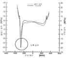
풀 스케일 FDM(full scale FDM)을 이용하여 추가 실험이 수행되며, 성형 가스 버너(H2/N2 5/95 믹스)에 기초한 가열기는 압축 응력 레인의 양측에서 기판을 국부적으로 재가열하도록 채용된다. 도 9는 균열 위치탐지 또는 멈춤 버너를 위한 열적 모델을 나타내는 그래프이다. 도 10은 균열 위치탐지 또는 멈춤 버너를 가진 유리 리본의 열-기계 그래프 분석이다. 도 9 및 10을 참고하여, 유동하는 유리 리본 상에 버너 화염의 열 충격이 발견될 수 있다. 예를 들어, 도 10에서, 결과는 버너가 활성화하지 않는 베이스 케이스 대 버너가 활성화하는(낮은 패널) 실험 케이스에 대해 제공된다. 관찰할 수 있는 바와 같이, 균열은 베이스 케이스에서 진행되는 것에 반하여(예, 압축 응력 밴드 진폭이 K1c를 초과하도록 K1에 대해 충분히 큰), 실험 케이스에서, 균열의 선단에서 발생된 인장 응력과 그 주변 영역은 버너가 활성화된 후 균열 위치를 탐지하거나 또는 균열을 멈출때 압축 응력으로 변형된다. Additional experiments are performed using full scale FDM (FDM), and heaters based on molded gas burners (H2 /
유리 리본의 균열 개시 및/또는 얇아짐에 대해, 도 11은 일련의 플롯(plot)으로서 유리 리본의 측면 상의 얇아짐으로 인한 유리 리본의 온도차 및 유도된 잔류 응력을 나타낸다. 도 4 및 11을 참고하여, 냉각 또는 가열 노즐, 제트, 레이저, IR 가열기, 버너(370a~h) 등은 유리 리본(304)의 일부분(305)을 '얇게' 하는데 사용될 수 있다. 도 11은 노즐(370a~h)로부터 출구 가스를 이용하여 유리 리본을 얇게하는 효과를 나타내며, 온도는 얇은 구역 또는 레인에서 더 낮으며 이로인해 압축 잔류 응력을 발생한다. 관찰될 수 있는 것처럼, 리본에서 발생하는 응력 차이는 유리 리본에서 균열을 개시하는데 단독으로 사용될 수 있거나 또는 개시를 위해 기계적인 수단도 이용될 수 있다. 공급된 가스는, 하위 범위를 포함하여, 약 20℃ 에서 약 1700℃ 범위, 약 500℃ 에서 약 1700℃ 범위, 약 700℃ 에서 약 1700℃ 범위, 약 750℃ 에서 약 850℃ 범위, 약 850℃ 에서 약 1450℃ 범위, 약 1450℃ 에서 약 1700℃ 범위의 온도로 제공될 수 있다. 물론, 공급된 온도는 각 노즐에 필요한 기능, 즉, 균열 개시, 균열 전파, 또는 균열 위치탐지 또는 멈춤에 따를 것이다. 예를 들어, 일부 실시예에서 가열 기계장치의 가스 온도는 약 150,000poise의 유동 점도에서 유리의 온도보다 적어도 100℃에서 적어도 200℃ 이상일 수 있다. 약 140,000poise의 점도를 가진 유리에서, 가열 기계장치의 가스 온도는 약 1040℃에서 약 1240℃ 사이의 범위에 있어야 한다. 상기 온도와 온도차는 그 사이의 하위 범위를 포함하여, 약 0.1MPa에서 약 50MPa 이상 사이, 약 1MPa에서 약 25MPa 사이, 또는 약 5MPa에서 약 20MPa 사이의 유리 리본의 압축 응력을 변경하기 위해(예, 감소시키기 위해) 예시의 실시예로서 채용될 수 있다. 실시예가 지금까지는 유리 리본을 참조하였지만, 본원에 첨부된 청구항은 실시예가 적층 구조물에 적용가능한 것으로(예, 하나 이상의 클래드 층(clad layers), 유리 웹 등), 한정되어서는 않된다. 예를 들어, 도 12는 다른 일련의 플롯(plot)으로서 유리 적층 리본의 측면 상에 얇아짐으로 인해 유리 적층 리본에서의 온도차와 유도된 잔류 응력을 나타낸다. 도 12를 참고하여, 적층 유리 리본의 제1 풀링 기계 높이에서의 얇은 영역에서의 냉각 효과가 관찰될 수 있으며, 좌측 패널은 얇아진 영역의 냉각으로 인한 온도의 차이를 나타내고, 우측 및 중앙 패널은 온도차이의 결과로서 증가한 응력을 나타낸다. 예시의 실시예에 의해 유도된 이러한 높은 압축 응력은 균열을 시작하는데 활용될 수 있으며 균열이 전파되게 하여 원치 않는 비드를 분리시킨다. 도 13 및 14는 적층 리본의 압축 응력의 플롯이다. 도 13 및 14를 참고하면, 높은 압축 응력은 미리 정해진 구역, 레인 또는 부분(305)에서 관찰될 수 있으며, 균열은 예시의 FDM(350)에서 위쪽으로 시작되고 전파되어 비드를 분리시킨다. 균열은 이후 추가 냉각 및/또는 가열 노즐, 버너 또는 제트(370)의 선택 활용을 통해 FDM(350)에서 멈춰질 수 있으며, 연속되는 유리 리본의 지속적인 비드 분리 공정을 야기할 수 있다. For crack initiation and / or thinning of the glass ribbon, Figure 11 shows the temperature difference and derived residual stress of the glass ribbon due to thinning on the side of the glass ribbon as a series of plots. 4 and 11, a cooling or heating nozzle, jet, laser, IR heater,
따라서, 일부 실시예에서, 냉각은 다음의 수식에 의해 설명될 수 있다:Thus, in some embodiments, cooling can be illustrated by the following equation: < RTI ID = 0.0 >
![]()
![]()
여기서, T는 유리 온도이며, y는 리본 상의 수직 좌표를 나타내고, ρ는 밀도, Cp는 열용량을 나타내고, t는 두께, U는 수직 리본 속도를 나타내며, h는 열 전달계수를 나타내고, Ta는 냉각 매체 또는 가스의 온도를 나타낸다. 수식(5)를 참고하면, 잔류 응력 발생이 온도 구배 ∂T/∂y와 직접 관련있고, 또한 온도 변화는 두께에 반비례한다고 결정되었다. 따라서, 높은 잔류 응력은 더 얇은 유리에서 발생될 수 있다. 일부 실시예에서 주어진 냉각 또는 가열 기계장치로부터의 잔류 응력이 오히려 유동 및 폭에 비례하는 가스 속도와 유리 두께의 곱에 의존할 수 있다. Where T is the glass temperature, y is the vertical coordinate on the ribbon, p is the density, Cp is the heat capacity, t is the thickness, U is the vertical ribbon speed, h is the heat transfer coefficient, It represents the temperature of the medium or gas. Referring to Eq. (5), it is determined that the residual stress generation is directly related to the temperature gradient ∂T / ∂y, and the temperature change is inversely proportional to the thickness. Thus, high residual stresses can be generated in thinner glass. In some embodiments, the residual stress from a given cooling or heating machinery may rather depend on the product of the glass velocity and the glass thickness proportional to flow and width.
일부 실시예에서, 노즐, 제트 또는 버너(370)는 점탄성 구역(예, 풀링롤(pulling rolls) 위의 리본의 일부분에서)에서 또는 그 위의 유리 표면에 작용하는 공기 제트를 이용하여 압축 응력 레인이 생성되었던 예시의 FDM(350)에 설치될 수 있다. 물론, 노즐, 제트 또는 버너(370)는 유리 리본의 탄성 구역에도 배치될 수 있으며, 따라서 이러한 예시는 본원에 첨부된 청구항의 범위에 제한되어서는 않된다. 예시의 노즐(370)의 가스 유동은 리본 상의 미리 정해진 위치에서의 균열을 제어하거나 위치 탐지하거나 멈추도록 조절될 수 있다. 예를 들어, 일부 실시예에서, 20scfh의 가스 유동은 노즐 중앙으로부터 약 50mm에서 진행되는 균열을 늦췄고 노즐 중앙으로부터 약 15mm에서 멈췄다. 상기 높이에서 균열 전파 속도는 리본 속도와 일치하며 균열은 안정하게 위치된다. 예시의 가스 유동은 그 사이의 모든 하위 범위를 포함하여 약 5 scfh에서 약 50 scfh, 약 10 scfh 에서 약 30 scfh 범위에 있을 수 있다. 가스의 온도와 더불어 각 노즐의 위치에 따른 공기유동은 유리 리본의 적절한 얇게 함과, 유리 리본의 압축 응력에 대한 적절한 변형 등을 제공하도록 바뀔 수 있으며, 균열을 제어가능하고 위치 확인이 가능하게 한다. 즉, 인발 아래의 국부적인 냉각 또는 가열(예, 유리 리본의 길이를 따른)은 유리 리본의 균열을 시작하고, 전파하고, 제어하고 위치탐지하나 멈추기 위한 예시의 실시예를 이용하여 조절될 수 있다. In some embodiments, the nozzle, jet, or
따라서, 본원에 게시된 실시예는 연속하는 유리 웹, 슬롯 인발, 플롯(float), 재인발으로부터, 또는 다른 성형 공정으로부터의 융합 성형 비드 분리 공정에서 유리 리본으로부터 가장자리 또는 비드를 제거하는 것과 관련된 여러 쟁점들을 다룬다. 하나의 상기 쟁점은 균열 선단의 위치의 안정화이다. 예를 들어, 리본 움직임의 방향 또는 그에 수직한 방향을 따른 균열 선단의 작은 움직임 조차도 작은 매끄러운 표면에서의 가장자리 품질의 저하를 야기할 수 있다. 그러나, 큰 움직임은 전체 리본 폭을 가로지르는 균열을 야기할 수 있다. 본원에 설명된 실시예는 열적 방법을 제공하여 균열 선단 주변의 응력을 변화시켜 그 위치를 안정화시키며 균열 선단 위치의 견고함을 리본에 대한 기계적 교란으로 개선시킬 수 있다.Thus, the embodiments disclosed herein are directed to a method and apparatus for removing edges or beads from a glass ribbon in a fused forming bead separation process from a continuous glass web, slot drawing, float, Address issues. One such issue is the stabilization of the location of the crack tip. For example, even small movements of the crack tip along the direction of the ribbon movement or a direction perpendicular thereto may cause a reduction in edge quality on a small smooth surface. However, large movements can cause cracks across the entire ribbon width. The embodiments described herein provide a thermal method to change the stress around the crack tip to stabilize its position and improve the robustness of the crack tip position to mechanical disturbance to the ribbon.
추가 실시예는 리본에 채용된 잔류 응력을 이용하여 기계적 전단 또는 균열 전파에 대한 다른 기계적 방법을 이용하는 것보다 균열 전파를 야기할 수 있다. Additional embodiments can cause crack propagation rather than utilizing mechanical stresses or other mechanical methods for crack propagation using the residual stresses employed in the ribbon.
일부 실시예는 얇아진 구역의 높은 압축 응력을 유도하는 유리 리본의 얇아진 구역에서 집중 냉각을 이용한다. 유리의 얇은 구역을 냉각함으로서 증가한 높은 잔류 응력은 제조 공정 및 장치에서 분리되기 위한 비드에 대한 조건을 생성할 수 있으며, 또는 수평 유리 분리를 제공하는데 사용될 수 있다. 다른 실시예에서, 유리 전이 체제에서의 집중 냉각은 비드 분리를 위해 균열의 전파를 용이하게 할 수 있는 잔류 응력을 얼릴 수 있다. 그러나, 특정 공정의 경우, 분리를 위한 균열을 전파하기 위해 충분히 높은 응력을 얼리기 필요한 냉각의 양은 비실용적일 수 있으며, 이러한 전파를 위치 탐지하거나 멈추기 위한 방법은 본원에 설명되어 있다. 물론, 예시의 실시예는 적층 유리 리본, 단일 유리 리본, 연속하는 유리 웹 등에 사용될 수 있다.Some embodiments utilize intensive cooling in a thinned area of the glass ribbon to induce high compressive stresses in the thinned areas. Increased residual stresses by cooling thin regions of the glass can create conditions for the beads to be separated in the manufacturing process and apparatus or can be used to provide horizontal glass separation. In another embodiment, centralized cooling in a glass transition regime may free residual stresses that may facilitate the propagation of cracks for bead separation. However, in the case of certain processes, the amount of cooling required to freeze stresses sufficiently high to propagate cracks for separation may be impractical, and methods for locating or stopping such radio waves are described herein. Of course, exemplary embodiments may be used for laminated glass ribbons, single glass ribbons, continuous glass webs, and the like.
따라서, 본 발명의 실시예를 이용한 예시의 융합 인발 기계(FDM)에서의 비드의 분리는, 유리 리본의 형태가 더욱 안정하고 평평해질 수 있으므로 높은 품질의 유리 시트를 생산하기 위한 프로세스 윈도우(process window)를 개시할 수 있으며, 압축, 뒤틀림, 응력 등과 같은 개선된 특성을 가진 제품을 생산하는 성형 공정을 가능하게 할 수 있다. 또한, 이와 같은 방식의 비드의 분리는 또한 일반적으로 종래의 비드 분리 방법(예, 스코어링 및 파괴)과 연관된 유리 시트에서의 접착된 유리의 양을 감소시킬 수 있다.Therefore, the separation of the beads in the exemplary Fusion Drawing Machine (FDM) using the embodiment of the present invention is advantageous in that the shape of the glass ribbon can be more stable and flat, so that the process window for producing a high quality glass sheet ) And may enable molding processes to produce products with improved properties such as compression, warping, stress, and the like. Also, the separation of beads in this manner can also generally reduce the amount of glued glass in the glass sheet associated with conventional bead separation methods (e.g., scoring and breaking).
압축 응력의 영역, 일부분, 레인, 또는 선을 가진 유리 리본을 포함하는 추가 실시예는 또한 레인 근처 구역의 온도를 변화시킴으로써 그 레인에서 위쪽으로의 균열 전파를 위치 탐지하거나 멈출 수 있다. 예를 들어, 가열 및/또는 냉각은 균열 전파를 멈추거나 위치 탐지하기 위해 선택적으로 채용될 수 있다. 따라서, 일부 실시예에서, 균열을 전파하는 것을 안내하는 압축 응력의 레인 내에서의 냉각은 균열 위치를 탐지하거나 멈추는데 사용될 수 있으며, 압축 응력의 레인과 바로 그 주변의 영역의 가열은 균열 위치를 탐지하거나 멈추는데 사용될 수 있고, 또는 가열 및 냉각 모두는 균열 전파를 위치 탐지하거나 멈추는데 사용될 수 있다. 추가 실시예는 유리한 물리적인 위치에서 균열 선단을 찾음으로써, 상류 또는 하류 리본 움직임을 방해하는 것으로부터 균열 전파를 격리할 수 있다.Additional embodiments, including glass ribbons having regions, portions, lanes, or lines of compressive stress, may also detect or stop crack propagation upward in the lane by varying the temperature of the zone near the lane. For example, heating and / or cooling may be selectively employed to stop or position crack propagation. Thus, in some embodiments, cooling in a lane of compressive stress guiding the propagation of cracks can be used to detect or stop the crack location, and heating of the lane of the compressive stress and the immediate vicinity of the cracks Can be used to detect or stop, or both heating and cooling can be used to locate or stop crack propagation. Additional embodiments can isolate crack propagation from disturbing upstream or downstream ribbon motion by looking for crack tips at favorable physical locations.
일부 실시예에서, 압축의 레인 내에 냉각을 사용하는 균열의 위치 또는 중단은 또한 냉각이 유리 세팅 구역 내에서 수행된 경우 하류에서 나타나는 임의의 잔류 압축 응력을 높일 수 있다. 따라서, 동일한 냉각 장치로 더 높은 유동 속도를 허용하는 초기의, 가장 높은 위치에서 덜 냉각하는 것이 요구될 수 있다. In some embodiments, the location or interruption of the cracks using cooling in the lanes of compression may also increase any residual compressive stresses that appear downstream when cooling is performed in the glass setting zone. Thus, it may be desirable to cool less in the initial, highest position that allows higher flow rates with the same cooling device.
일부 실시예가 융합 성형에 적용 가능한 것으로 설명되었지만, 본원에 첨부된 청구항은 본원에 설명된 방법, 시스템 및 장치가 균열이 전파되게 하는 잔류 응력 밴드를 가진 임의의 유리 리본에 사용될 수 있다는 것에 한정되지 않아야 한다는 것을 알아야 한다.Although some embodiments have been described as being applicable to fusion molding, the claims appended hereto should not be limited to the fact that the methods, systems and apparatuses described herein can be used in any glass ribbon with residual stress bands causing crack propagation You should know that.
다양한 공지된 실시예가 특정 실시예와 관련되어 설명된 특정 특징, 요소 또는 단계들을 포함할 수 있다는 것을 이해할 것이다. 또한, 특정 특징, 요소 또는 단계는, 하나의 특정 실시예와 관련되어 설명되었지만, 다양한 도시되지 않은 조합 또는 순열에서 대체 실시예와 상호 교환되거나 결합될 수 있음을 이해할 것이다. It will be appreciated that various known embodiments may include the specific features, elements or steps described in connection with the specific embodiments. In addition, it is to be understood that a particular feature, element, or step has been described in connection with one specific embodiment, but may be interchanged or combined with alternative embodiments in various non-illustrated combinations or permutations.
또한, 본원에 사용된 것처럼, "그", "한", 또는 "하나"의 용어는, "적어도 하나"를 의미하고, 명백히 반대로 나타내지 않는 한, "오직 하나"만으로 한정되어서는 안된다는 것을 이해할 것이다. 따라서, 예를 들어, "하나의 구성요소"는 명백히 달리 나타내지 않는 한, 두 개 이상의 구성요소를 가진 예시를 포함한다.Also, as used herein, the terms "the", "one", or "one" shall mean "at least one" and should not be limited to "only one" unless expressly stated to the contrary . Thus, for example, "one component" includes an example having two or more components, unless expressly stated otherwise.
범위는 "약" 하나의 특정 값에서, 및/또는 "약" 다른 하나의 값으로 본원에 표현될 수 있다. 상기 범위가 표현된 경우, 예시는 하나의 특정 값에서 및/또는 다른 특정 값으로를 포함한다. 유사하게, "약"이라는 전제의 사용을 통해, 값이 근사치로 표현된 경우, 특정 값이 또 다른 양상을 형성한다는 것을 이해할 것이다. 범위의 각각의 말단값이 다른 말단값과 관련되어, 그리고 다른 말단값과 독립적으로 모두 중요하다는 것을 또한 이해할 것이다.The range may be expressed herein as "about" one particular value, and / or "about" another value. When the range is expressed, the example includes from one specific value and / or to another specific value. Similarly, it will be appreciated that, through the use of the premise of "about, " when a value is expressed as an approximation, the particular value forms another aspect. It will also be appreciated that each end value of the range is related to the other end value, and both are important independently of the other end value.
본원에 사용된 것과 같은, "실질적인", "실질적으로"라는 용어와, 그 변형은 설명된 특징이 하나의 값 또는 설명과 같거나 또는 거의 같다는 것을 나타내기 위한 것이다. 더욱이, "실질적으로 유사한"은 두 개의 값이 같거나 거의 같다는 것을 나타내기 위한 것이다. 일부 실시예에서, "실질적으로 유사한"은 서로 약 10% 이내의 값, 예컨대 서로 약 5% 이내, 또는 서로 약 2% 이내의 값을 나타낼 수 있다.The terms "substantial "," substantially ", and variations thereof, such as those used herein, are intended to indicate that the features described are the same or substantially the same as one value or description. Moreover, "substantially similar" is intended to indicate that two values are equal or substantially equal. In some embodiments, "substantially similar" may represent values within about 10% of each other, e.g., within about 5% of each other, or within about 2% of each other.
달리 명시되어 있지 않는 한, 본원에 제시된 임의의 방법이 특정 순서로 수행되는 단계를 필요로 하는 것으로 해석되는 것은 아니다. 따라서, 방법 청구항은 실제로 그 단계가 따라야하는 순서를 재인용하지 않으며 또는 단계가 특정 순서에 한정된다고 청구항 또는 설명에 달리 명시되지 않으며, 특정 순서가 암시되는 것은 결코 아니다. Unless otherwise specified, it is to be understood that any method presented herein is not to be construed as requiring a step to be performed in any particular order. Accordingly, a method claim does not reiterate the order in which the step should actually be followed, nor is it explicitly stated in the claims or the description that the step is limited to a particular order, and the particular order is by no means implied.
특정 실시예의 다양한 특징, 요소 또는 단계가 과도적인 구문 "포함하는"을 이용하여 설명될 수 있지만, 과도적인 구문 "구성하는", 또는 "본질적으로 구성하는"을 이용하여 설명될 수 있는 것들을 포함하는 대안 실시예가 함축되어 있는 것으로 이해되어야 한다. 따라서, 예를 들어, A+B+C를 포함하는 장치에 대한 함축된 대안 실시예는 장치가 A+B+C로 구성되는 실시예와 장치가 본질적으로 A+B+C로 구성되는 실시예를 포함한다.While various features, elements, or steps of a particular embodiment may be described using transitional phrases "comprising ", it should be understood that the phrase " comprising ", or" consisting essentially of " Alternative embodiments are to be understood as being implied. Thus, for example, an implied alternative embodiment for an apparatus comprising A + B + C is an embodiment in which the apparatus is composed of A + B + C and an embodiment in which the apparatus consists essentially of A + B + C .
본 발명의 의미와 범주에서 벗어나지 않는 한 본 발명에 다양한 수정 및 변형이 가능하다는 것은 당업자에게 명백할 것이다. 당업자가 본 발명의 의미와 본질을 포함하는 게시된 실시예의 수정 결합, 하위-결합 및 변형을 수행할 수 있기 때문에, 본 발명은 첨부된 청구항의 범위와 그 등가물 내에 모든 것을 포함하는 것으로 해석되어야 한다.It will be apparent to those skilled in the art that various modifications and variations can be made in the present invention without departing from the spirit and scope of the invention. As those of ordinary skill in the art will be able to make modifications, sub-combinations, and modifications of the published embodiments that include the meaning and essence of the present invention, the present invention should be construed as including all of the scope of the appended claims and their equivalents .
Claims (42)
상기 연속으로 이동하는 유리 리본에서 수직 균열을 개시하기 위한 제1 가열 또는 냉각 장치;
상기 연속으로 이동하는 유리 리본에서 개시된 균열 위치를 탐지하거나 또는 개시된 균열을 멈추기 위한 제2 가열 또는 냉각 장치; 및
상기 연속으로 이동하는 유리 리본을 유리 시트로 수평으로 분리하도록 구성되며, 상기 제1 및 제2 가열 또는 냉각 장치의 하류의 분리 기계장치;를 포함하는 유리 리본을 형성하는 장치.A forming body configured to have a molten glass comprising a converging forming surface connected at a root and forming a continuously moving glass ribbon drawn from the root;
A first heating or cooling device for initiating vertical cracking in the continuously moving glass ribbon;
A second heating or cooling device for detecting a crack location disclosed in said continuously moving glass ribbon or for stopping said cracks; And
And a separating mechanism configured to horizontally separate the continuously moving glass ribbon into a glass sheet, the separating mechanism downstream of the first and second heating or cooling apparatuses.
상기 제2 가열 또는 냉각 장치는 상기 제1 가열 또는 냉각 장치의 하류에 있는, 유리 리본을 형성하는 장치.The method according to claim 1,
Wherein the second heating or cooling device is downstream of the first heating or cooling device.
상기 제1 및 제2 가열 또는 냉각 장치는 노즐, 제트(jet), 레이저, IR 가열기 및 버너 중 적어도 하나를 포함하는, 유리 리본을 형성하는 장치.The method according to claim 1,
Wherein the first and second heating or cooling devices comprise at least one of a nozzle, a jet, a laser, an IR heater and a burner.
상기 연속으로 이동하는 유리 리본은 제1 온도로 있으며, 상기 제1 가열 또는 냉각 장치는 상기 제1 온도보다 낮은 제2 온도로 상기 연속으로 이동하는 유리 리본에 가스를 전달하도록 구성되는, 유리 리본을 형성하는 장치.The method according to claim 1,
Wherein the continuously moving glass ribbon is at a first temperature and the first heating or cooling device is configured to deliver gas to the continuously moving glass ribbon at a second temperature lower than the first temperature, Lt; / RTI >
상기 연속으로 이동하는 유리 리본은 제1 온도로 있으며, 상기 제1 가열 또는 냉각 장치는 상기 제1 온도보다 높은 제2 온도로 상기 연속으로 이동하는 유리 리본에 가스를 전달하도록 구성되는, 유리 리본을 형성하는 장치.The method according to claim 1,
Wherein the continuously moving glass ribbon is at a first temperature and wherein the first heating or cooling device is configured to deliver gas to the continuously moving glass ribbon at a second temperature higher than the first temperature, Lt; / RTI >
상기 제1 및 제1 가열 또는 냉각 장치의 하류에 또는 상기 제1 가열 또는 냉각 장치의 하류와 상기 제2 가열 또는 냉각 장치의 상류에 제3 가열 또는 냉각 장치를 더 포함하는, 유리 리본을 형성하는 장치.The method according to claim 1,
Further comprising a third heating or cooling device downstream of the first and first heating or cooling device or downstream of the first heating or cooling device and upstream of the second heating or cooling device, Device.
상기 가스는 공기, 질소, 수소, 가연성 가스, 불활성 가스 및 이들의 조합으로 이루어진 그룹에서 선택되는, 유리 리본을 형성하는 장치.The method according to claim 4 or 5,
Wherein the gas is selected from the group consisting of air, nitrogen, hydrogen, a combustible gas, an inert gas, and combinations thereof.
상기 분리 기계장치는 레이저 기계장치, 기계 스코어링(scoring) 기계장치, 및 하나 이상의 추가 가열 또는 냉각 장치 중 적어도 하나를 이용하여 유리를 분리하는, 유리 리본을 형성하는 장치.The method according to claim 1,
Wherein the separating machine device separates the glass using at least one of a laser machine, a machine scoring machine, and one or more additional heating or cooling devices.
상기 연속으로 이동하는 유리 리본은 약 0.01mm에서 약 5mm 사이의 두께를 갖는, 유리 리본을 형성하는 장치.The method according to claim 1,
Wherein the continuously moving glass ribbon has a thickness between about 0.01 mm and about 5 mm.
상기 제2 가열 기계장치는 상기 루트의 하류에 약 2500mm에서 약 7500mm 사이에 위치하는, 유리 리본을 형성하는 장치.The method according to claim 1,
Wherein the second heating mechanism is located between about 2500 mm and about 7500 mm downstream of the route.
상기 제1 가열 기계장치는 상기 제2 가열 기계장치의 상류에 약 500mm에서 약 5500mm 사이에 위치하는, 유리 리본을 형성하는 장치.The method according to claim 1,
Wherein the first heating mechanism is located between about 500 mm and about 5500 mm upstream of the second heating mechanism.
상기 연속으로 이동하는 유리 리본을 유동 방향으로 분리하기 위한 제1 가열 또는 냉각 장치; 및
상기 루트 전에 상기 연속으로 이동하는 유리 리본의 분리 위치를 탐지하거나 또는 분리를 멈추기 위한 제2 가열 또는 냉각 장치;를 포함하는 유리 리본을 형성하는 장치.A forming body configured to have a molten glass comprising a converging forming surface connected at the root and forming a continuously moving glass ribbon drawn from the root;
A first heating or cooling device for separating the continuously moving glass ribbon in the flow direction; And
And a second heating or cooling device for detecting the separation position of the continuously moving glass ribbon before said route or for stopping the separation.
상기 연속으로 이동하는 유리 리본을 유리 시트로 수평으로 분리하도록 구성되며, 상기 제1 및 제2 가열 또는 냉각 장치의 하류에 있는 분리 기계장치를 더 포함하는, 유리 리본을 형성하는 장치.14. The method of claim 13,
Further comprising a separating mechanism configured to horizontally separate the continuously moving glass ribbon into a glass sheet and downstream of the first and second heating or cooling devices.
상기 제1 및 제1 가열 또는 냉각 장치의 하류에 또는 상기 제1 가열 또는 냉각 장치의 하류와 상기 제2 가열 또는 냉각 장치의 상류에 제3 가열 또는 냉각 장치를 더 포함하는, 유리 리본을 형성하는 장치.14. The method of claim 13,
Further comprising a third heating or cooling device downstream of the first and first heating or cooling device or downstream of the first heating or cooling device and upstream of the second heating or cooling device, Device.
상기 제2 가열 또는 냉각 장치는 상기 제1 가열 또는 냉각 장치의 하류에 있는, 유리 리본을 형성하는 장치.14. The method of claim 13,
Wherein the second heating or cooling device is downstream of the first heating or cooling device.
상기 제1 및 제2 가열 또는 냉각 장치는 노즐, 제트(jet), 레이저, IR 가열기 및 버너 중 적어도 하나를 포함하는, 유리 리본을 형성하는 장치.14. The method of claim 13,
Wherein the first and second heating or cooling devices comprise at least one of a nozzle, a jet, a laser, an IR heater and a burner.
상기 연속으로 이동하는 유리 리본은 제1 온도로 있으며, 상기 제1 가열 또는 냉각 장치는 상기 제1 온도보다 낮은 제2 온도로 상기 연속으로 이동하는 유리 리본에 가스를 전달하도록 구성되는, 유리 리본을 형성하는 장치.14. The method of claim 13,
Wherein the continuously moving glass ribbon is at a first temperature and the first heating or cooling device is configured to deliver gas to the continuously moving glass ribbon at a second temperature lower than the first temperature, Lt; / RTI >
상기 연속으로 이동하는 유리 리본은 제1 온도로 있으며, 상기 제1 가열 또는 냉각 장치는 상기 제1 온도보다 높은 제2 온도로 상기 연속으로 이동하는 유리 리본에 가스를 전달하도록 구성되는, 유리 리본을 형성하는 장치.14. The method of claim 13,
Wherein the continuously moving glass ribbon is at a first temperature and wherein the first heating or cooling device is configured to deliver gas to the continuously moving glass ribbon at a second temperature higher than the first temperature, Lt; / RTI >
상기 가스는 공기, 질소, 수소, 가연성 가스, 불활성 가스 및 이들의 조합으로 이루어진 그룹에서 선택되는, 유리 리본을 형성하는 장치.The method according to claim 18 or 19,
Wherein the gas is selected from the group consisting of air, nitrogen, hydrogen, a combustible gas, an inert gas, and combinations thereof.
상기 분리 기계장치는 레이저 기계장치, 기계 스코어링(scoring) 기계장치, 및 하나 이상의 추가 가열 또는 냉각 장치 중 적어도 하나를 이용하여 유리를 분리하는, 유리 리본을 형성하는 장치.15. The method of claim 14,
Wherein the separating machine device separates the glass using at least one of a laser machine, a machine scoring machine, and one or more additional heating or cooling devices.
상기 연속으로 이동하는 유리 리본은 분리 기계장치 이후 약 0.01mm에서 약 5mm 사이의 두께를 갖는, 유리 리본을 형성하는 장치.14. The method of claim 13,
Wherein the continuously moving glass ribbon has a thickness between about 0.01 mm and about 5 mm after the separating machine.
상기 제2 가열 기계장치는 상기 루트의 하류에 약 2500mm에서 약 7500mm 사이에 위치하는, 유리 리본을 형성하는 장치.14. The method of claim 13,
Wherein the second heating mechanism is located between about 2500 mm and about 7500 mm downstream of the route.
상기 제1 가열 기계장치는 상기 제2 가열 기계장치의 상류에 약 500mm에서 약 5500mm 사이에 위치하는, 유리 리본을 형성하는 장치.14. The method of claim 13,
Wherein the first heating mechanism is located between about 500 mm and about 5500 mm upstream of the second heating mechanism.
상기 연속으로 이동하는 유리 리본의 점탄성 영역에서 균열을 개시하기 위한 제1 가열 또는 냉각 장치; 및
상기 연속으로 이동하는 유리 리본에서 개시된 균열 위치를 탐지하거나 또는 균열을 멈추기 위한 제2 가열 또는 냉각 장치;를 포함하는, 유리 리본을 형성하는 장치.A forming body configured to draw a continuously moving glass ribbon;
A first heating or cooling device for initiating cracking in the viscoelastic region of the continuously moving glass ribbon; And
And a second heating or cooling device for detecting cracks or stopping cracks in said continuously moving glass ribbon.
상기 성형 바디는 상기 성형 바디의 루트에서 연결되는 수렴 성형 표면을 더 포함하며, 상기 성형 바디는 상기 루트에서 인발된 연속으로 이동하는 유리 리본을 형성하는 용융된 유리를 갖도록 구성되는, 유리 리본을 형성하는 장치.27. The method of claim 26,
Wherein the forming body further comprises a converging forming surface connected at the root of the forming body and the forming body is configured to have a molten glass forming a continuously moving glass ribbon withdrawn from the root, .
상기 개시된 균열이 유동 방향에 있는, 유리 리본을 형성하는 장치.27. The method of claim 26,
Wherein said cracks are in the flow direction.
상기 개시된 균열이 유동 방향에 수직인, 유리 리본을 형성하는 장치.27. The method of claim 26,
Wherein said cracks are perpendicular to the flow direction.
상기 연속으로 이동하는 유리 리본을 유리 시트로 분리하도록 구성되며, 상기 제1 및 제2 가열 또는 냉각 장치의 하류에 있는 분리 기계장치를 더 포함하는, 유리 리본을 형성하는 장치.27. The method of claim 26,
Further comprising a separating mechanism configured to separate the continuously moving glass ribbon into a glass sheet and downstream of the first and second heating or cooling apparatus.
상기 제2 가열 또는 냉각 장치는 상기 제1 가열 또는 냉각 장치의 하류에 있는, 유리 리본을 형성하는 장치.27. The method of claim 26,
Wherein the second heating or cooling device is downstream of the first heating or cooling device.
상기 제1 및 제1 가열 또는 냉각 장치의 하류에 또는 상기 제1 가열 또는 냉각 장치의 하류와 상기 제2 가열 또는 냉각 장치의 상류에 제3 가열 또는 냉각 장치를 더 포함하는, 유리 리본을 형성하는 장치.27. The method of claim 26,
Further comprising a third heating or cooling device downstream of the first and first heating or cooling device or downstream of the first heating or cooling device and upstream of the second heating or cooling device, Device.
상기 제1 및 제2 가열 또는 냉각 장치는 노즐, 제트(jet), 레이저, IR 가열기 및 버너 중 적어도 하나를 포함하는, 유리 리본을 형성하는 장치.27. The method of claim 26,
Wherein the first and second heating or cooling devices comprise at least one of a nozzle, a jet, a laser, an IR heater and a burner.
상기 연속으로 이동하는 유리 리본은 제1 온도로 있으며, 상기 제1 가열 또는 냉각 장치는 상기 제1 온도보다 낮은 제2 온도로 상기 연속으로 이동하는 유리 리본에 가스를 전달하도록 구성되는, 유리 리본을 형성하는 장치.27. The method of claim 26,
Wherein the continuously moving glass ribbon is at a first temperature and the first heating or cooling device is configured to deliver gas to the continuously moving glass ribbon at a second temperature lower than the first temperature, Lt; / RTI >
상기 연속으로 이동하는 유리 리본은 제1 온도로 있으며, 상기 제1 가열 또는 냉각 장치는 상기 제1 온도보다 높은 제2 온도로 상기 연속으로 이동하는 유리 리본에 가스를 전달하도록 구성되는, 유리 리본을 형성하는 장치.27. The method of claim 26,
Wherein the continuously moving glass ribbon is at a first temperature and wherein the first heating or cooling device is configured to deliver gas to the continuously moving glass ribbon at a second temperature higher than the first temperature, Lt; / RTI >
상기 가스는 공기, 질소, 수소, 가연성 가스, 불활성 가스 및 이들의 조합으로 이루어진 그룹에서 선택되는, 유리 리본을 형성하는 장치.35. The method of claim 34 or 35,
Wherein the gas is selected from the group consisting of air, nitrogen, hydrogen, a combustible gas, an inert gas, and combinations thereof.
상기 분리 기계장치는 레이저 기계장치, 기계 스코어링(scoring) 기계장치, 및 하나 이상의 추가 가열 또는 냉각 장치 중 적어도 하나를 이용하여 유리를 분리하는, 유리 리본을 형성하는 장치.32. The method of claim 30,
Wherein the separating machine device separates the glass using at least one of a laser machine, a machine scoring machine, and one or more additional heating or cooling devices.
상기 연속으로 이동하는 유리 리본은 약 0.01mm에서 약 5mm 사이의 두께를 갖는, 유리 리본을 형성하는 장치.27. The method of claim 26,
Wherein the continuously moving glass ribbon has a thickness between about 0.01 mm and about 5 mm.
상기 제2 가열 기계장치는 상기 루트의 하류에 약 2500mm에서 약 7500mm 사이에 위치하는, 유리 리본을 형성하는 장치.28. The method of claim 27,
Wherein the second heating mechanism is located between about 2500 mm and about 7500 mm downstream of the route.
상기 제1 가열 기계장치는 상기 제2 가열 기계장치의 상류에 약 500mm에서 약 5500mm 사이에 위치하는, 유리 리본을 형성하는 장치.27. The method of claim 26,
Wherein the first heating mechanism is located between about 500 mm and about 5500 mm upstream of the second heating mechanism.
상기 제1 가열 또는 냉각 장치는 그 각각의 유리 전이 온도로 유리 리본의 일부분으로부터 상류에 있는, 유리 리본을 형성하는 장치.The method according to claim 1, 14 or 26,
Wherein the first heating or cooling device is upstream from a portion of the glass ribbon at its respective glass transition temperature.
Applications Claiming Priority (3)
| Application Number | Priority Date | Filing Date | Title |
|---|---|---|---|
| US201562134827P | 2015-03-18 | 2015-03-18 | |
| US62/134,827 | 2015-03-18 | ||
| PCT/US2016/022784 WO2016149458A1 (en) | 2015-03-18 | 2016-03-17 | Methods and apparatuses for removing edges of a glass ribbon |
Publications (1)
| Publication Number | Publication Date |
|---|---|
| KR20170129224A true KR20170129224A (en) | 2017-11-24 |
Family
ID=56919346
Family Applications (1)
| Application Number | Title | Priority Date | Filing Date |
|---|---|---|---|
| KR1020177029865A KR20170129224A (en) | 2015-03-18 | 2016-03-17 | Method and apparatus for removing the edge of a glass ribbon |
Country Status (6)
| Country | Link |
|---|---|
| US (1) | US20180093913A1 (en) |
| JP (1) | JP2018512362A (en) |
| KR (1) | KR20170129224A (en) |
| CN (1) | CN107635933A (en) |
| TW (1) | TW201714845A (en) |
| WO (1) | WO2016149458A1 (en) |
Families Citing this family (5)
| Publication number | Priority date | Publication date | Assignee | Title |
|---|---|---|---|---|
| DE102015104801A1 (en) * | 2015-03-27 | 2016-09-29 | Schott Ag | Method and apparatus for continuous separation of glass |
| JP6980532B2 (en) | 2015-05-18 | 2021-12-15 | コーニング インコーポレイテッド | Methods and systems for processing glass ribbons |
| CN113333967A (en) * | 2021-06-04 | 2021-09-03 | 浙江华工光润智能装备技术有限公司 | Splitting method and splitting device for laser cutting of glass |
| WO2023003703A1 (en) * | 2021-07-20 | 2023-01-26 | Corning Incorporated | Apparatus and methods for separating edge portions from a glass ribbon |
| CN114956533B (en) * | 2022-05-07 | 2023-10-03 | 河北省沙河玻璃技术研究院 | Preparation method and device for ultrathin flexible glass |
Family Cites Families (15)
| Publication number | Priority date | Publication date | Assignee | Title |
|---|---|---|---|---|
| US4828900A (en) * | 1987-12-23 | 1989-05-09 | Ppg Industries, Inc. | Discrete glass cutting and edge shaping |
| DE19918936A1 (en) * | 1999-04-27 | 2000-11-02 | Schott Glas | Method and device for producing single glass panes |
| FR2819505B1 (en) * | 2001-01-12 | 2003-02-28 | Saint Gobain | PROCESS FOR CUTTING THE EDGES OF A CONTINUOUS GLASS TAPE, IMPLEMENTATION DEVICE, GLASS TRAY CUT ACCORDING TO THIS PROCEDURE |
| WO2005054142A1 (en) * | 2003-12-05 | 2005-06-16 | Asahi Glass Company, Limited | Method and device for cutting plate glass |
| US20060042314A1 (en) * | 2004-08-27 | 2006-03-02 | Abbott John S Iii | Noncontact glass sheet stabilization device used in fusion forming of a glass sheet |
| DE102006024825A1 (en) * | 2006-05-23 | 2007-11-29 | Jenoptik Automatisierungstechnik Gmbh | Method and device for edge trimming a float glass ribbon |
| US8539795B2 (en) * | 2009-05-13 | 2013-09-24 | Corning Incorporated | Methods for cutting a fragile material |
| US8132427B2 (en) * | 2009-05-15 | 2012-03-13 | Corning Incorporated | Preventing gas from occupying a spray nozzle used in a process of scoring a hot glass sheet |
| EP2253598B1 (en) * | 2009-05-21 | 2014-05-14 | Corning Incorporated | Apparatus for reducing radiative heat loss from a forming body in a glass forming process |
| US8245539B2 (en) * | 2010-05-13 | 2012-08-21 | Corning Incorporated | Methods of producing glass sheets |
| JP5617556B2 (en) * | 2010-11-22 | 2014-11-05 | 日本電気硝子株式会社 | Strip glass film cleaving apparatus and strip glass film cleaving method |
| US8528365B2 (en) * | 2011-02-24 | 2013-09-10 | Corning Incorporated | Apparatus for removing volatilized materials from an enclosed space in a glass making process |
| TWI548598B (en) * | 2011-02-28 | 2016-09-11 | 康寧公司 | Fusion draw apparatus and methods |
| TWI591026B (en) * | 2011-11-30 | 2017-07-11 | 康寧公司 | Apparatus and method for removing edge portions from a continuously moving glass ribbon |
| US10239778B2 (en) * | 2013-12-03 | 2019-03-26 | Corning Incorporated | Apparatus and method for severing a glass sheet |
-
2016
- 2016-03-17 KR KR1020177029865A patent/KR20170129224A/en unknown
- 2016-03-17 US US15/559,239 patent/US20180093913A1/en not_active Abandoned
- 2016-03-17 CN CN201680028149.8A patent/CN107635933A/en active Pending
- 2016-03-17 JP JP2017549014A patent/JP2018512362A/en active Pending
- 2016-03-17 WO PCT/US2016/022784 patent/WO2016149458A1/en active Application Filing
- 2016-03-18 TW TW105108512A patent/TW201714845A/en unknown
Also Published As
| Publication number | Publication date |
|---|---|
| JP2018512362A (en) | 2018-05-17 |
| CN107635933A (en) | 2018-01-26 |
| WO2016149458A1 (en) | 2016-09-22 |
| US20180093913A1 (en) | 2018-04-05 |
| TW201714845A (en) | 2017-05-01 |
Similar Documents
| Publication | Publication Date | Title |
|---|---|---|
| KR20170129224A (en) | Method and apparatus for removing the edge of a glass ribbon | |
| TWI771321B (en) | Apparatus and method for processing a glass substrate | |
| JP6128531B2 (en) | Apparatus and method for locally thinning a continuously moving glass ribbon | |
| TWI555709B (en) | Apparatus and method for forming glass sheets | |
| TWI519492B (en) | Manufacture of glass plates | |
| KR20070015232A (en) | Defect reduction in manufacture glass sheets by fusion process | |
| TWI605022B (en) | Glass substrate for display | |
| CN107635930A (en) | Reduce mechanical stress and carry out continuous processing flexible glass band | |
| KR20140107233A (en) | Apparatus for producing molten glass, method for producing molten glass, and method for producing plate glass using said apparatus and method | |
| JP2019513668A (en) | Glass manufacturing method and apparatus | |
| JP6489783B2 (en) | Glass substrate manufacturing method and glass substrate manufacturing apparatus | |
| JP2019094245A (en) | Float glass production method and float glass | |
| KR20190038367A (en) | Method for manufacturing glass substrate | |
| US10377654B2 (en) | Apparatus and method of manufacturing composite glass articles | |
| CN109836029B (en) | Float glass manufacturing apparatus, float glass manufacturing method, and float glass | |
| JP2016124751A (en) | Manufacturing method and manufacturing device for glass substrate for display | |
| CN114644446A (en) | Float glass manufacturing device, float glass manufacturing method, and float glass | |
| JP2019064846A (en) | Method and apparatus for manufacturing glass substrate | |
| JP2022098453A (en) | Float glass production device, float glass production method, and float glass | |
| CN114075031A (en) | Float glass manufacturing device and float glass manufacturing method |