KR20170128055A - Wireless power transmitter and method for controlling thereof - Google Patents
Wireless power transmitter and method for controlling thereof Download PDFInfo
- Publication number
- KR20170128055A KR20170128055A KR1020160145039A KR20160145039A KR20170128055A KR 20170128055 A KR20170128055 A KR 20170128055A KR 1020160145039 A KR1020160145039 A KR 1020160145039A KR 20160145039 A KR20160145039 A KR 20160145039A KR 20170128055 A KR20170128055 A KR 20170128055A
- Authority
- KR
- South Korea
- Prior art keywords
- electronic device
- wireless power
- group
- power transmission
- cells
- Prior art date
Links
- 238000000034 method Methods 0.000 title claims description 50
- 230000005540 biological transmission Effects 0.000 claims abstract description 174
- 238000004891 communication Methods 0.000 claims abstract description 22
- 238000001514 detection method Methods 0.000 claims description 11
- 230000008859 change Effects 0.000 description 12
- 238000010586 diagram Methods 0.000 description 6
- 238000012546 transfer Methods 0.000 description 6
- 230000014509 gene expression Effects 0.000 description 5
- 230000008901 benefit Effects 0.000 description 3
- 238000005516 engineering process Methods 0.000 description 2
- 230000010363 phase shift Effects 0.000 description 2
- 239000004186 Penicillin G benzathine Substances 0.000 description 1
- 230000015572 biosynthetic process Effects 0.000 description 1
- 238000004364 calculation method Methods 0.000 description 1
- 239000012141 concentrate Substances 0.000 description 1
- 238000011161 development Methods 0.000 description 1
- 238000006073 displacement reaction Methods 0.000 description 1
- 230000000694 effects Effects 0.000 description 1
- 238000005562 fading Methods 0.000 description 1
- 239000002803 fossil fuel Substances 0.000 description 1
- 239000011521 glass Substances 0.000 description 1
- 230000006698 induction Effects 0.000 description 1
- 230000002452 interceptive effect Effects 0.000 description 1
- 238000012986 modification Methods 0.000 description 1
- 230000004048 modification Effects 0.000 description 1
- 230000008569 process Effects 0.000 description 1
- 238000003672 processing method Methods 0.000 description 1
- 230000001172 regenerating effect Effects 0.000 description 1
- 230000008054 signal transmission Effects 0.000 description 1
- 230000008685 targeting Effects 0.000 description 1
- 238000005406 washing Methods 0.000 description 1
Images


Classifications
-
- H—ELECTRICITY
- H02—GENERATION; CONVERSION OR DISTRIBUTION OF ELECTRIC POWER
- H02J—CIRCUIT ARRANGEMENTS OR SYSTEMS FOR SUPPLYING OR DISTRIBUTING ELECTRIC POWER; SYSTEMS FOR STORING ELECTRIC ENERGY
- H02J50/00—Circuit arrangements or systems for wireless supply or distribution of electric power
- H02J50/20—Circuit arrangements or systems for wireless supply or distribution of electric power using microwaves or radio frequency waves
-
- H—ELECTRICITY
- H01—ELECTRIC ELEMENTS
- H01Q—ANTENNAS, i.e. RADIO AERIALS
- H01Q21/00—Antenna arrays or systems
- H01Q21/06—Arrays of individually energised antenna units similarly polarised and spaced apart
- H01Q21/061—Two dimensional planar arrays
- H01Q21/065—Patch antenna array
-
- H—ELECTRICITY
- H01—ELECTRIC ELEMENTS
- H01Q—ANTENNAS, i.e. RADIO AERIALS
- H01Q3/00—Arrangements for changing or varying the orientation or the shape of the directional pattern of the waves radiated from an antenna or antenna system
- H01Q3/26—Arrangements for changing or varying the orientation or the shape of the directional pattern of the waves radiated from an antenna or antenna system varying the relative phase or relative amplitude of energisation between two or more active radiating elements; varying the distribution of energy across a radiating aperture
- H01Q3/28—Arrangements for changing or varying the orientation or the shape of the directional pattern of the waves radiated from an antenna or antenna system varying the relative phase or relative amplitude of energisation between two or more active radiating elements; varying the distribution of energy across a radiating aperture varying the amplitude
-
- H—ELECTRICITY
- H01—ELECTRIC ELEMENTS
- H01Q—ANTENNAS, i.e. RADIO AERIALS
- H01Q3/00—Arrangements for changing or varying the orientation or the shape of the directional pattern of the waves radiated from an antenna or antenna system
- H01Q3/26—Arrangements for changing or varying the orientation or the shape of the directional pattern of the waves radiated from an antenna or antenna system varying the relative phase or relative amplitude of energisation between two or more active radiating elements; varying the distribution of energy across a radiating aperture
- H01Q3/30—Arrangements for changing or varying the orientation or the shape of the directional pattern of the waves radiated from an antenna or antenna system varying the relative phase or relative amplitude of energisation between two or more active radiating elements; varying the distribution of energy across a radiating aperture varying the relative phase between the radiating elements of an array
- H01Q3/34—Arrangements for changing or varying the orientation or the shape of the directional pattern of the waves radiated from an antenna or antenna system varying the relative phase or relative amplitude of energisation between two or more active radiating elements; varying the distribution of energy across a radiating aperture varying the relative phase between the radiating elements of an array by electrical means
- H01Q3/36—Arrangements for changing or varying the orientation or the shape of the directional pattern of the waves radiated from an antenna or antenna system varying the relative phase or relative amplitude of energisation between two or more active radiating elements; varying the distribution of energy across a radiating aperture varying the relative phase between the radiating elements of an array by electrical means with variable phase-shifters
-
- H—ELECTRICITY
- H01—ELECTRIC ELEMENTS
- H01Q—ANTENNAS, i.e. RADIO AERIALS
- H01Q9/00—Electrically-short antennas having dimensions not more than twice the operating wavelength and consisting of conductive active radiating elements
- H01Q9/04—Resonant antennas
- H01Q9/0407—Substantially flat resonant element parallel to ground plane, e.g. patch antenna
-
- H—ELECTRICITY
- H02—GENERATION; CONVERSION OR DISTRIBUTION OF ELECTRIC POWER
- H02J—CIRCUIT ARRANGEMENTS OR SYSTEMS FOR SUPPLYING OR DISTRIBUTING ELECTRIC POWER; SYSTEMS FOR STORING ELECTRIC ENERGY
- H02J50/00—Circuit arrangements or systems for wireless supply or distribution of electric power
- H02J50/005—Mechanical details of housing or structure aiming to accommodate the power transfer means, e.g. mechanical integration of coils, antennas or transducers into emitting or receiving devices
-
- H—ELECTRICITY
- H02—GENERATION; CONVERSION OR DISTRIBUTION OF ELECTRIC POWER
- H02J—CIRCUIT ARRANGEMENTS OR SYSTEMS FOR SUPPLYING OR DISTRIBUTING ELECTRIC POWER; SYSTEMS FOR STORING ELECTRIC ENERGY
- H02J50/00—Circuit arrangements or systems for wireless supply or distribution of electric power
- H02J50/20—Circuit arrangements or systems for wireless supply or distribution of electric power using microwaves or radio frequency waves
- H02J50/23—Circuit arrangements or systems for wireless supply or distribution of electric power using microwaves or radio frequency waves characterised by the type of transmitting antennas, e.g. directional array antennas or Yagi antennas
-
- H—ELECTRICITY
- H02—GENERATION; CONVERSION OR DISTRIBUTION OF ELECTRIC POWER
- H02J—CIRCUIT ARRANGEMENTS OR SYSTEMS FOR SUPPLYING OR DISTRIBUTING ELECTRIC POWER; SYSTEMS FOR STORING ELECTRIC ENERGY
- H02J50/00—Circuit arrangements or systems for wireless supply or distribution of electric power
- H02J50/40—Circuit arrangements or systems for wireless supply or distribution of electric power using two or more transmitting or receiving devices
- H02J50/402—Circuit arrangements or systems for wireless supply or distribution of electric power using two or more transmitting or receiving devices the two or more transmitting or the two or more receiving devices being integrated in the same unit, e.g. power mats with several coils or antennas with several sub-antennas
-
- H—ELECTRICITY
- H02—GENERATION; CONVERSION OR DISTRIBUTION OF ELECTRIC POWER
- H02J—CIRCUIT ARRANGEMENTS OR SYSTEMS FOR SUPPLYING OR DISTRIBUTING ELECTRIC POWER; SYSTEMS FOR STORING ELECTRIC ENERGY
- H02J50/00—Circuit arrangements or systems for wireless supply or distribution of electric power
- H02J50/80—Circuit arrangements or systems for wireless supply or distribution of electric power involving the exchange of data, concerning supply or distribution of electric power, between transmitting devices and receiving devices
-
- H—ELECTRICITY
- H02—GENERATION; CONVERSION OR DISTRIBUTION OF ELECTRIC POWER
- H02J—CIRCUIT ARRANGEMENTS OR SYSTEMS FOR SUPPLYING OR DISTRIBUTING ELECTRIC POWER; SYSTEMS FOR STORING ELECTRIC ENERGY
- H02J50/00—Circuit arrangements or systems for wireless supply or distribution of electric power
- H02J50/90—Circuit arrangements or systems for wireless supply or distribution of electric power involving detection or optimisation of position, e.g. alignment
-
- H—ELECTRICITY
- H02—GENERATION; CONVERSION OR DISTRIBUTION OF ELECTRIC POWER
- H02J—CIRCUIT ARRANGEMENTS OR SYSTEMS FOR SUPPLYING OR DISTRIBUTING ELECTRIC POWER; SYSTEMS FOR STORING ELECTRIC ENERGY
- H02J7/00—Circuit arrangements for charging or depolarising batteries or for supplying loads from batteries
- H02J7/0047—Circuit arrangements for charging or depolarising batteries or for supplying loads from batteries with monitoring or indicating devices or circuits
-
- H—ELECTRICITY
- H02—GENERATION; CONVERSION OR DISTRIBUTION OF ELECTRIC POWER
- H02J—CIRCUIT ARRANGEMENTS OR SYSTEMS FOR SUPPLYING OR DISTRIBUTING ELECTRIC POWER; SYSTEMS FOR STORING ELECTRIC ENERGY
- H02J7/00—Circuit arrangements for charging or depolarising batteries or for supplying loads from batteries
- H02J7/02—Circuit arrangements for charging or depolarising batteries or for supplying loads from batteries for charging batteries from ac mains by converters
-
- H02J7/025—
-
- H—ELECTRICITY
- H04—ELECTRIC COMMUNICATION TECHNIQUE
- H04B—TRANSMISSION
- H04B5/00—Near-field transmission systems, e.g. inductive or capacitive transmission systems
- H04B5/70—Near-field transmission systems, e.g. inductive or capacitive transmission systems specially adapted for specific purposes
- H04B5/79—Near-field transmission systems, e.g. inductive or capacitive transmission systems specially adapted for specific purposes for data transfer in combination with power transfer
Landscapes
- Engineering & Computer Science (AREA)
- Power Engineering (AREA)
- Computer Networks & Wireless Communication (AREA)
- Signal Processing (AREA)
- Waveguide Aerials (AREA)
- Charge And Discharge Circuits For Batteries Or The Like (AREA)
- Radar Systems Or Details Thereof (AREA)
Abstract
Description
본 발명은 무선 전력 전송장치 및 그 제어 방법에 관한 것으로, 더욱 상세하게는 전자장치에게 무선으로 전력을 송신할 수 있는 무선 전력 전송장치 및 그 제어 방법에 관한 것이다.The present invention relates to a wireless power transmission apparatus and a control method thereof, and more particularly, to a wireless power transmission apparatus capable of wirelessly transmitting power to an electronic apparatus and a control method thereof.
현대를 살아가는 많은 사람들에게 휴대용 디지털 통신기기들은 하나의 필수 요소가 되었다. 소비자들은 언제 어디서나 자신이 원하는 다양한 고품질의 서비스를 제공받고 싶어한다. 뿐만 아니라, 최근 IoT (internet of things) 기술의 발달로 인하여 우리 생활 속에 존재하는 각종 센서, 가전기기, 통신기기 등은 네트워크화 되고 있다. 이러한 각종 센서 및 기기들을 원활하게 동작시키기 위해서는 무선 전력 전송 시스템이 필요하다.Portable digital communication devices have become an essential element for many people living in modern times. Consumers want to be provided with various high-quality services that they want whenever and wherever they want. In addition, due to the recent development of IoT (internet of things) technology, various sensors, home appliances, and communication devices existing in our daily lives are being networked. A wireless power transmission system is required to operate these various sensors and devices smoothly.
무선 전력 전송은 자기유도, 자기공진, 그리고 전자기파 방식이 있으며, 그 중 전자기파 방식은 다른 방식에 비해 원거리 전력 전송에 보다 유리하다는 장점이 있다.The wireless power transmission has the advantages of magnetic induction, self resonance, and electromagnetic wave method, among which the electromagnetic wave method is more advantageous in the remote power transmission than the other methods.
전자기파 방식은 주로 원거리 전력 전송에 사용되며, 원거리에 있는 전력 수신기의 정확한 위치를 파악하여 전력을 가장 효율적으로 전달하는 것이 관건이다.The electromagnetic wave method is mainly used for remote power transmission, and it is important to determine the exact position of the power receiver at a long distance and to transmit the power most efficiently.
전자기파 방식은 복수의 셀 안테나를 사용하여 무선 전력에 대응하는 전자파를 방사하는데, 타겟(무선 전력 수신장치 또는 전자장치)이 있는 위치에 따라 각각의 셀 안테나에서 방사되는 무선 전력에 대응하는 전자기파의 위상 및 크기를 제어하여 효율적으로 무선 전력을 전달한다.In the electromagnetic wave system, a plurality of cell antennas are used to emit electromagnetic waves corresponding to radio power, and the phase of an electromagnetic wave corresponding to the radio power radiated from each cell antenna depending on the position of the target (radio power receiving apparatus or electronic apparatus) And size to efficiently deliver wireless power.
전자기파 방식을 이용하여 무선 전력을 전송하는 경우 무선 전력을 필요로 하는 전자장치가 2개 이상인 경우 각각의 전자장치에게 무선 전력을 적절히 분배하여 전송해야 한다. 종래에는 복수의 셀 안테나를 무선 전력을 수신하는 전자장치의 개수에 맞춰 동일한 개수로 분할하여 그룹을 생성하고, 생성된 그룹에 전력을 분배하여 무선 전력을 전송했다.In the case of transmitting wireless power using the electromagnetic wave method, when there are two or more electronic devices requiring wireless power, it is necessary to appropriately distribute and transmit the wireless power to each electronic device. Conventionally, a plurality of cell antennas are divided into equal numbers in accordance with the number of electronic apparatuses receiving radio power to generate groups, and power is distributed by distributing power to the generated groups.
본 개시의 실시 예에 따른 무선 전력 전송장치는 무선 전력을 필요로 하는 전자장치의 개수, 전자장치의 위치 및 거리에 따라 복수의 셀 안테나를 동적으로 그룹핑하여 무선 전력을 분배함으로써 효율적으로 무선 전력을 전송할 수 있다. 본 개시에 따르면 각 그룹에 포함된 셀 안테나의 개수는 무선 전력을 수신하는 전자장치에 따라 상이할 수 있다.A wireless power transmission apparatus according to an embodiment of the present disclosure efficiently divides wireless power by dynamically grouping a plurality of cell antennas according to the number of electronic devices requiring the wireless power, Lt; / RTI > According to the present disclosure, the number of cell antennas included in each group may vary depending on the electronic device receiving the wireless power.
본 개시의 실시 예에 따른 무선 전력 전송장치는, 무선 전력을 수신하는 전자장치가 전송하는 정보를 수신 하는 통신부; 무선 전력을 방사하는 복수의 셀을 포함하는 어레이(array) 안테나; 및 상기 통신부를 통해 상기 전자장치가 전송한 정보를 수신하고 상기 정보에 기초하여 상기 어레이 안테나에 포함된 복수의 셀을 조합하여 상기 전자장치에 대응하는 그룹을 생성하고, 상기 그룹에 포함된 복수의 셀을 제어하는 제어부;를 포함한다.A wireless power transmission apparatus according to an embodiment of the present disclosure includes a communication unit that receives information transmitted by an electronic device that receives wireless power; An array antenna including a plurality of cells emitting radio power; And a control unit configured to receive the information transmitted by the electronic device through the communication unit and generate a group corresponding to the electronic device by combining a plurality of cells included in the array antenna based on the information, And a control unit for controlling the cell.
본 개시의 다른 실시 예에 따른 복수의 셀로 구성된 어레이 안테나를 포함하는 무선 전력 전송장치의 전력 전송 방법은, 전자장치로부터 정보를 수신하는 단계; 상기 수신된 정보에 기초하여 상기 어레이 안테나를 구성하는 복수의 셀을 조합하여 상기 전자장치에 대응하는 그룹을 생성하는 단계; 및 상기 생성된 그룹에 포함된 복수의 셀을 제어하는 단계;를 포함한다.A power transmission method of a wireless power transmission apparatus including an array antenna composed of a plurality of cells according to another embodiment of the present disclosure includes: receiving information from an electronic device; Generating a group corresponding to the electronic device by combining a plurality of cells constituting the array antenna based on the received information; And controlling a plurality of cells included in the generated group.
본 개시의 실시 예에 따르면, 무선 전력 전송장치는 무선 전력을 수신하는 전자장치가 전송하는 정보에 기초하여 무선 전력을 방사하는 복수의 셀을 조합하여 전자장치에 대응하는 그룹을 생성하고, 그룹에 포함된 복수의 셀을 제어함으로써 효율적으로 무선 전력을 공급할 수 있다.According to an embodiment of the present disclosure, a wireless power transmission device combines a plurality of cells radiating wireless power based on information transmitted by an electronic device receiving wireless power to generate a group corresponding to the electronic device, The wireless power can be efficiently supplied by controlling a plurality of included cells.
도 1은 본 개시의 실시예에 따른 무선 전력 전송장치 및 무선 전력 수신 장치의 개념도를 도시한다.
도 2는 본 개시의 실시 예에 따른 무선 전력 전송장치의 어레이 안테나에서 다양한 방향으로 RF 웨이브를 방사하는 예를 도시한다.
도 3은 본 개시의 실시예에 따른 무선 전력 전송장치의 블록도를 도시한다.
도 4a 내지 도 4c는 본 발명의 다양한 실시 예에 따른 어레이 안테나에서 형성되는 무선 전력 필드를 개념적으로 도시한다.
도 5a 내지 도 5c는 무선 전력 전송장치가 어레이 안테나를 구성하는 셀의 위상을 제어하여 복수의 전자장치로 전력을 전송하는 예를 도시한다.
도 6은 어레이 안테나를 구성하는 복수의 셀이 무선 전력을 전송하기 위해 그룹핑되는 예를 도시한다
도 7은 무선 전력 전송장치가 하나의 전자장치를 충전하는 도중에 새로운 전자장치가 검출되어 그룹을 재생성 하는 예를 도시한다.
도 8은 무선 전력 전송장치가 두 개의 전자장치를 충전하는 도중에 또 다른 전자장치가 검출되어 그룹을 재생성 하는 예를 도시한다.
도 9는 본 개시의 실시예에 따른 무선 전력 전송장치가 무선전력을 수신하는 전자장치에 따라 어레이 안테나에 포함된 셀을 조합하여 그룹을 생성하고 제어하는 방법에 대한 흐름도이다.
도 10은 본 개시의 실시예에 따른 무선 전력 전송장치가 전자장치를 무선 충전하는 중에 새로운 전자장치를 추가로 검출하여 그룹을 재생성하는 방법에 대한 흐름도이다.
도 11은 본 개시의 실시예에 따른 무선 전력 전송장치가 최대 파워로 전자장치를 충전하는 중에 새로운 전자장치가 검출되는 경우 충전 우선 순위를 결정하는 방법에 대한 흐름도이다.1 shows a conceptual diagram of a wireless power transmission apparatus and a wireless power reception apparatus according to an embodiment of the present disclosure.
2 shows an example of radiating an RF wave in various directions in an array antenna of a wireless power transmission device according to an embodiment of the present disclosure.
3 shows a block diagram of a wireless power transmission apparatus according to an embodiment of the present disclosure;
FIGS. 4A through 4C conceptually show a wireless power field formed in an array antenna according to various embodiments of the present invention.
5A to 5C show examples in which a wireless power transmission apparatus controls the phase of a cell constituting an array antenna to transmit power to a plurality of electronic devices.
6 shows an example in which a plurality of cells constituting the array antenna are grouped to transmit radio power
7 shows an example in which a new electronic device is detected and a group is regenerated while the wireless power transmission device is charging one electronic device.
Fig. 8 shows an example in which another electronic device is detected and the group is regenerated while the wireless power transmission device charges two electronic devices.
9 is a flow chart of a method of combining and combining groups of cells included in an array antenna according to an electronic device in which a wireless power transmission apparatus according to an embodiment of the present disclosure receives wireless power.
10 is a flowchart of a method for further detecting a new electronic device to regenerate a group while the wireless power transmission device according to the embodiment of the present disclosure wirelessly charges the electronic device.
11 is a flow diagram of a method for determining charge priorities when a new electronic device is detected while the wireless power transfer device charges the electronic device at full power according to an embodiment of the present disclosure;
이하, 본 개시의 다양한 실시 예들이 첨부된 도면을 참조하여 기재된다. 실시 예 및 이에 사용된 용어들은 본 개시에 기재된 기술을 특정한 실시 형태에 대해 한정하려는 것이 아니며, 해당 실시 예의 다양한 변경, 균등물, 및/또는 대체물을 포함하는 것으로 이해되어야 한다. 도면의 설명과 관련하여, 유사한 구성요소에 대해서는 유사한 참조 부호가 사용될 수 있다. Hereinafter, various embodiments of the present disclosure will be described with reference to the accompanying drawings. It is to be understood that the embodiments and terminology used herein are not to be considered as limiting the invention to the particular embodiments described, but to include various modifications, equivalents, and / or alternatives of the embodiments. In connection with the description of the drawings, like reference numerals may be used for similar components.
단수의 표현은 문맥상 명백하게 다르게 뜻하지 않는 한, 복수의 표현을 포함할 수 있다. 본 개시에서, "A 또는 B" 또는 "A 및/또는 B 중 적어도 하나" 등의 표현은 함께 나열된 항목들의 모든 가능한 조합을 포함할 수 있다. "제 1," "제 2," "첫째," 또는 "둘째,"등의 표현들은 해당 구성요소들을, 순서 또는 중요도에 상관없이 수식할 수 있고, 한 구성요소를 다른 구성요소와 구분하기 위해 사용될 뿐 해당 구성요소들을 한정하지 않는다. 어떤(예: 제 1) 구성요소가 다른(예: 제 2) 구성요소에 "(기능적으로 또는 통신적으로) 연결되어" 있다거나 "접속되어" 있다고 언급된 때에는, 상기 어떤 구성요소가 상기 다른 구성요소에 직접적으로 연결되거나, 다른 구성요소(예: 제 3 구성요소)를 통하여 연결될 수 있다.The singular expressions may include plural expressions unless the context clearly dictates otherwise. In this disclosure, expressions such as "A or B" or "at least one of A and / or B" and the like may include all possible combinations of the items listed together. Expressions such as " first, "" second," " first, "or" second, " But is not limited to those components. When it is mentioned that some (e.g., first) component is "(functionally or communicatively) connected" or "connected" to another (second) component, May be connected directly to the component, or may be connected through another component (e.g., a third component).
본 개시에서, "~하도록 구성된(또는 설정된)(configured to)"은 상황에 따라, 예를 들면, 하드웨어적 또는 소프트웨어적으로 "~에 적합한," "~하는 능력을 가지는," "~하도록 변경된," "~하도록 만들어진," "~를 할 수 있는," 또는 "~하도록 설계된"과 상호 호환적으로(interchangeably) 사용될 수 있다. 어떤 상황에서는, "~하도록 구성된 장치"라는 표현은, 그 장치가 다른 장치 또는 부품들과 함께 "~할 수 있는" 것을 의미할 수 있다. 예를 들면, 문구 "A, B, 및 C를 수행하도록 구성된(또는 설정된) 제어부"는 해당 동작을 수행하기 위한 전용 제어부(예: 임베디드 제어부), 또는 메모리 장치에 저장된 하나 이상의 소프트웨어 프로그램들을 실행함으로써, 해당 동작들을 수행할 수 있는 범용 제어부(예: CPU 또는 application processor)를 의미할 수 있다. In this disclosure, "configured to (or configured to)" as used herein is intended to encompass all types of information, such as, for example, hardware or software, , "" Made to "," can do ", or" designed to ". In some situations, the expression "a device configured to" may mean that the device can "do " with other devices or components. For example, a control unit configured (or configured) to perform the phrases "A, B, and C" may be implemented by executing a dedicated control unit (e.g., an embedded control) , And a general purpose control unit (e.g., a CPU or an application processor) capable of performing the corresponding operations.
본 개시의 다양한 실시 예들에 따른 무선 전력 수신장치는 무선 전력을 수신하는 전자장치이며, 예를 들면, 스마트폰, 태블릿 PC, 이동 전화기, 영상 전화기, 전자책 리더기, 데스크탑 PC, 랩탑 PC, 넷북 컴퓨터, 워크스테이션, 서버, PDA, PMP(portable multimedia player), MP3 플레이어, 의료기기, 카메라, 또는 웨어러블 장치 중 적어도 하나를 포함할 수 있다. 웨어러블 장치는 액세서리형(예: 시계, 반지, 팔찌, 발찌, 목걸이, 안경, 콘택트 렌즈, 또는 머리 착용형 장치(head-mounted-device(HMD)), 직물 또는 의류 일체형(예: 전자 의복), 신체 부착형(예: 스킨 패드 또는 문신), 또는 생체 이식형 회로 중 적어도 하나를 포함할 수 있다. 어떤 실시 예들에서, 무선 전력 수신장치는, 예를 들면, 텔레비전, DVD(digital video disk) 플레이어, 오디오, 냉장고, 에어컨, 청소기, 오븐, 전자레인지, 세탁기, 공기 청정기, 셋톱 박스, 홈 오토매이션 컨트롤 패널, 보안 컨트롤 패널, 미디어 박스(예: 삼성 HomeSyncTM, 애플TVTM, 또는 구글 TVTM), 게임 콘솔(예: XboxTM, PlayStationTM), 전자 사전, 전자 키, 캠코더, 또는 전자 액자 중 적어도 하나를 포함할 수 있다. 또한 무선 전력 수신장치는 사물인터넷 장치(IoT: internet of things) 및 사물인터넷 센서를 포함할 수 있다. A wireless power receiving device in accordance with various embodiments of the present disclosure is an electronic device that receives wireless power and may be, for example, a smart phone, a tablet PC, a mobile phone, a video phone, an electronic book reader, a desktop PC, a laptop PC, , A workstation, a server, a PDA, a portable multimedia player (PMP), an MP3 player, a medical device, a camera, or a wearable device. Wearable devices may be of the type of accessories (eg, watches, rings, bracelets, braces, necklaces, glasses, contact lenses or head-mounted-devices (HMD) (E.g., a skin pad or a tattoo), or a bio-implantable circuit. In some embodiments, the wireless power receiving device may include at least one of a television, a digital video disk (Such as Samsung HomeSync TM , Apple TV TM , or Google TV TM TM) , audio, refrigerator, air conditioner, vacuum cleaner, oven, microwave oven, washing machine, air purifier, set top box, home automation control panel, ), A game console (e.g., Xbox TM , PlayStation TM ), an electronic dictionary, an electronic key, a camcorder, or an electronic photo frame, etc. The wireless power receiving device may also include an Internet of things (IoT) And things Internet sensors .
또한 무선 전력 수신장치는 스마트 자동차(smart car)를 포함할 수 있다. 스마트 자동차는 차세대 전기 전자, 정보 통신, 제어 기술을 접목하여 자동차의 내/외부 상황을 실시간으로 인식하는 자동차를 의미할 수 있다. 스마트 자동차는 커넥티드 자동차(connected car)라고도 칭해진다. 스마트 자동차는 화석 연료가 아닌 전기 배터리를 이용하여 구동될 수 있으므로 전기 자동차를 포함하는 의미일 수 있다. The wireless power receiving device may also include a smart car. Smart cars can mean automobiles that recognize the inside / outside situation of a car in real time by combining next-generation electric and electronic, information communication, and control technology. Smart cars are also referred to as connected cars. Smart cars can be driven by electric batteries rather than fossil fuels, which can mean electric vehicles.
본 개시의 실시 예에 따른 무선 전력 수신장치는 전술한 기기들에 한정되지 않는다. The wireless power receiving apparatus according to the embodiment of the present disclosure is not limited to the above-described apparatuses.
본 개시에서 "사용자"란 무선 전력 전송장치 또는 무선 전력 수신장치를 조작하는 사람을 의미할 수 있다. 또한, "사용자"란 무선 전력 전송장치 또는 무선 전력 수신장치의 조작을 수행하는 장치(예: 인공지능 무선 전력 수신장치 또는 로봇 등)를 지칭할 수 있다.In this disclosure, "user" may refer to a person operating a wireless power transmission device or wireless power receiving device. Further, the term "user" may refer to a wireless power transmission device or an apparatus (e.g., an artificial intelligent wireless power receiving device or a robot) that performs operations of the wireless power receiving device.
본 개시에서 "어레이 안테나" 는 "복수의 셀 안테나"를 의미한다.In the present disclosure, the term "array antenna" means "a plurality of cell antennas ".
본 개시에서 "셀"은 "셀 안테나"를 의미한다.In this disclosure, "cell" means "cell antenna ".
본 개시에서 "무선 전력"은 "셀에서 방사되는 전자기파"를 의미할 수 있다.In the present disclosure, "wireless power" may mean "electromagnetic waves radiated from a cell ".
본 개시에서 "빔"은 복수 개의 전자기파의 크기와 위상을 제어하여, 보강 간섭을 통해 특정 위치로 전자기파가 집중되는 것을 의미한다.In the present disclosure, the term "beam" means that the magnitude and phase of a plurality of electromagnetic waves are controlled to concentrate electromagnetic waves to a specific position through constructive interference.
본 개시에서 무선 전력 전송장치가 전자장치를 충전한다는 것은 전자장치로 무선 전력을 전송 한다는 의미 또는 셀에서 전자장치를 향해 무선 전력에 대응하는 전자기파를 방사하는 의미일 수 있다. In this disclosure, the charging of an electronic device by a wireless power transmission device may mean transmitting wireless power to the electronic device, or it may mean emitting electromagnetic waves corresponding to wireless power from the cell to the electronic device.
이하 첨부된 도면을 참조하여, 본 개시의 실시 예들을 상세히 설명한다.Embodiments of the present disclosure will now be described in detail with reference to the accompanying drawings.
도 1은 본 개시의 실시예에 따른 무선 전력 전송장치 및 무선 전력 수신 장치의 개념도를 도시한다.1 shows a conceptual diagram of a wireless power transmission apparatus and a wireless power reception apparatus according to an embodiment of the present disclosure.
무선 전력 수신장치는 무선으로 전력을 수신할 수 있는 전자장치를 의미한다. 이하의 설명에서는 전자장치는 무선 전력 수신장치를 의미하는 것으로 사용될 수 있다. A wireless power receiving device refers to an electronic device capable of receiving power wirelessly. In the following description, the electronic device can be used to mean a wireless power receiving device.
무선 전력 전송장치(100)는 적어도 하나의 전자장치(150,160)에게 무선으로 전력을 송신할 수 있다. 본 개시의 실시예에서, 무선 전력 전송장치(100)는 복수 개의 셀 안테나 (111 내지 126)를 포함할 수 있다. 셀 안테나(111 내지 126)는 RF(radio frequency) 웨이브를 발생시킬 수 있는 안테나라면 제한이 없다. 셀 안테나(111 내지 126)가 발생시키는 RF 웨이브의 진폭 및 위상 중 적어도 하나는 무선 전력 전송장치(100)에 의하여 조정될 수 있다. 설명의 편의를 위하여, 셀 안테나(111 내지 126) 각각이 발생시키는 RF 웨이브를 서브 RF 웨이브라 명명하도록 한다. The wireless
또한 각각의 셀 안테나(111 내지 126)를 '셀', 2개 이상의 셀 안테나를 그룹핑(grouping) 한 것을 '그룹' 으로 명명하도록 한다.Also, each of the
본 개시의 다양한 실시예에서, 무선 전력 전송장치(100)는 셀 안테나(111 내지 126)에서 방사되는 서브 RF 웨이브 각각의 진폭 및 위상 중 적어도 하나를 조정할 수 있다. 한편, 각 셀 안테나에서 방사된 서브 RF 웨이브들은 서로 간섭될 수 있다. 예를 들어, 어느 한 지점에서는 서브 RF 웨이브들이 서로 보강 간섭될 수 있으며, 또 다른 지점에서는 서브 RF 웨이브들이 서로 상쇄 간섭될 수 있다. 본 개시의 실시 예에 따른 무선 전력 전송장치(100)는 제 1 지점(x1,y1,z1)에서 서브 RF 웨이브들이 서로 보강 간섭될 수 있도록, 셀 안테나(111 내지 126)가 발생하는 서브 RF 웨이브 각각의 진폭 및 위상 중 적어도 하나를 조정할 수 있다. 즉, 무선 전력 전송 장치(100)는 각 셀 안테나에서 생성된 서브 RF 웨이브의 진폭 또는 위상 중 적어도 하나를 조정하여, 임의의 위치에서 각 서브 RF 웨이브가 보강 간섭을 일으켜 무선 전력 전달을 위한 RF 웨이브가 최대 진폭을 형성하도록 각 셀 안테나를 제어할 수 있다.In various embodiments of the present disclosure, the wireless
예를 들어, 무선 전력 전송장치(100)는 제 1 지점(x1,y1,z1)에 전자장치(150)가 배치된 것을 결정할 수 있다. 여기에서, 전자장치(150)의 위치는, 예를 들어 전자장치(150)의 전력 수신용 안테나가 위치한 지점일 수 있다. 무선 전력 전송장치(100)가 전자장치(150)의 위치를 결정하는 구성에 대해서는 더욱 상세하게 후술하도록 한다. 전자장치(150)가 높은 효율로 무선 전력을 수신하기 위하여서는, 제 1 지점(x1,y1,z1)에서 각 셀 안테나에서 방사된 서브 RF 웨이브들이 보강 간섭되어야 한다. 이에 따라, 무선 전력 전송장치(100)는 제 1 지점(x1,y1,z1)에서 서브 RF 웨이브들이 서로 보강 간섭이 되도록 셀 안테나(111 내지 126)를 제어할 수 있다. 여기에서, 셀 안테나(111 내지 126)를 제어한다는 것은, 셀 안테나(111 내지 126)로 입력되는 신호의 크기를 제어하거나 또는 셀 안테나(111 내지 126)로 입력되는 신호의 위상(또는 딜레이)을 제어하는 것을 의미할 수 있다. For example, the wireless
한편, 특정 지점에서 RF 웨이브가 보강 간섭되도록 제어하는 기술인 빔-포밍(beam forming)에 대하여서는 당업자가 용이하게 이해할 수 있을 것이다. 아울러, 본 발명에서 이용되는 빔-포밍의 종류에 대하여 제한이 없으며 또한 당업자가 용이하게 이해할 수 있을 것이다. 빔-포밍에 의하여 형성된 RF 웨이브를, 에너지 포켓(pockets of energy)이라 명명할 수도 있다.Meanwhile, beam forming, which is a technique for controlling the RF wave to be constructive interference at a specific point, will be easily understood by those skilled in the art. In addition, there is no limitation on the type of beam-forming used in the present invention, and it will be easily understood by those skilled in the art. An RF wave formed by beam-forming may also be referred to as pockets of energy.
서브 RF 웨이브들에 의하여 형성된 RF 웨이브(130)는 제 1 지점(x1,y1,z1)에서 진폭이 최대가 될 수 있으며, 이에 따라 전자장치(150)는 높은 효율로 무선 전력을 수신할 수 있다. 한편, 무선 전력 전송장치(100)는 제 2 지점(x2,y2,z2)에 전자장치(160)가 배치된 것을 결정할 수도 있다. 무선 전력 전송장치(100)는 전자장치(160)를 충전하기 위하여 서브 RF 웨이브들이 제 2 지점(x2,y2,z2)에서 보강 간섭이 되도록 셀 안테나(111 내지 126)를 제어할 수 있다. 이에 따라, 복수의 셀들에서 방사된 서브 RF 웨이브들에 의하여 형성된 RF 웨이브(140)는 제 2 지점(x2,y2,z2)에서 진폭이 최대가 될 수 있으며, 이에 따라 전자장치(160)는 높은 효율로 무선 전력을 수신할 수 있다.The
상술한 바와 같이, 무선 전력 전송장치(100)는 전자장치(150,160)의 위치를 결정하고, 결정된 위치에서 서브 RF 웨이브들이 보강 간섭이 되게 하여, 높은 송신 효율로 무선 충전을 수행할 수 있다. As described above, the wireless
도 2는 본 개시의 실시 예에 따른 무선 전력 전송장치의 어레이 안테나에서 다양한 방향으로 RF 웨이브를 방사하는 예를 도시한다.2 shows an example of radiating an RF wave in various directions in an array antenna of a wireless power transmission device according to an embodiment of the present disclosure.
도 2를 참조하면, 제 1 셀 안테나(111), 제 2 셀 안테나(112), 제 3 셀 안테나(113) 및 제 4 셀 안테나(114) 각각은 특정 방향으로 빔을 포밍(forming)하기 위해 서로 다른 진폭과 위상을 갖는 서브 RF 웨이브를 방사하도록 제어될 수 있으며, 각 셀에서는 제어된 진폭과 위상으로 생성된 서브 RF 웨이브(501,502,503,504)를 형성할 수 있다. Referring to FIG. 2, each of the
형성된 서브 RF 웨이브는 전체 어레이 안테나의 셀의 개수와 동일 할 수 있으나, 무선 전력 전송의 효율 증대를 위해 적절한 빔 포밍을 할 경우 빔의 개수는 전체 어레이 셀의 개수 보다 줄어들 수 있다. 즉, 무선 충전을 필요로 하는 전자 장치의 개수에 의해 빔의 개수는 조정될 수 있으며 이에 필요한 빔의 개수는 전체 어레이 안테나의 셀의 개수 보다 작을 수 있다.The number of beams may be less than the number of all array cells when appropriate beamforming is performed to increase the efficiency of the wireless power transmission, although the number of formed sub RF waves may be the same as the number of cells of the entire array antenna. That is, the number of beams may be adjusted by the number of electronic devices requiring wireless charging, and the number of beams required may be less than the number of cells of the entire array antenna.
도 3은 본 개시의 실시예에 따른 무선 전력 전송장치의 블록도를 도시한다. 3 shows a block diagram of a wireless power transmission apparatus according to an embodiment of the present disclosure;
무선 전력 전송장치(600)는 전력 소스(source)(601), 전력 송신용 어레이 안테나(610), 제어부(620), 메모리(660) 및 통신 회로(640)를 포함할 수 있다. The wireless
전자장치(650)는 무선으로 전력을 수신하는 장치이면 제한이 없으며, 전력 수신용 안테나(651), 정류기(652), 컨터버(653), 차저(charger)(654), 제어부(655), 메모리(656) 및 통신 회로(657)를 포함할 수 있다. 전력 수신용 안테나(651)는 복수의 셀을 포함하는 어레이 안테나일 수 있다.The
전력 소스(601)는 전력 송신용 어레이 안테나(610)에서 무선 전력 송신을 위해 필요한 전력을 전력 송신용 어레이 안테나(610)로 제공할 수 있다. 전력 소스(601)는, 예를 들어 직류 전력을 제공할 수 있으며, 이 경우에는 직류 전력을 교류 전력으로 변환하여 전력 송신용 어레이 안테나(610)로 전달하는 인버터(inverter)(미도시)가 무선 전력 전송장치(600)에 더 포함될 수도 있다. 한편, 다른 실시예에서는, 전력 소스(601)는 교류 전력을 전력 송신용 어레이 안테나(610)로 제공할 수도 있다.The
전력 송신용 어레이 안테나(610)는 복수 개의 셀 안테나들을 포함할 수 있다. 예를 들어, 도 1에 도시된 바와 같은 복수 개의 셀 안테나들이 전력 송신용 어레이 안테나(610)에 포함될 수 있다. 어레이 안테나(610)를 구성하는 셀 안테나의 개수 또는 배열 형태에 대하여서는 제한이 없다. 전력 송신용 어레이 안테나(610)는 전력 소스(601)로부터 제공받은 전력을 이용하여, RF 웨이브를 형성할 수 있다. 전력 송신용 어레이 안테나(610)는 제어부(620)의 제어에 따라서, 특정 방향으로 RF 웨이브를 형성할 수 있다. 여기에서, 특정 방향으로 RF 웨이브를 형성한다는 것은, 특정 방향의 일 지점에서의 서브 RF 웨이브들이 보강 간섭을 일으키도록, 서브 RF 웨이브들의 진폭 및 위상 중 적어도 하나를 제어함을 의미할 수 있다.The power
제어부(620)는 무선 전력을 수신하는 전자장치의 위치를 결정하기 위해 어레이 안테나를 통해 파일럿 신호를 송신할 수 있다. 구체적으로 제어부(620)는, 전력 송신용 어레이 안테나(610)가 복수 개의 방향 각각으로 충전 대상인 전자 장치(650)를 검출하기 위한 RF 웨이브, 즉 파일럿 신호 각각을 형성하도록 제어할 수 있다. 여기에서 충전 대상인 전자 장치를 검출하기 위해 전송되는 RF 웨이브를 검출용 RF 웨이브라 명명한다. 파일럿 신호를 이용하여 전자 장치를 검출하는 방법에 대해서는 후술할 것이다.The
상술한 바와 같이 무선 전력 전송 장치는 어레이 안테나를 통해 무선 전력 송신뿐만 아니라, 무선 전력을 수신하는 전자장치의 위치를 파악하기 위해 RF 웨이브인 파일럿 신호를 송신할 수 있다.As described above, the wireless power transmission apparatus can transmit not only the wireless power transmission through the array antenna, but also the pilot signal which is an RF wave in order to locate the electronic apparatus receiving the wireless power.
또한, 무선 전력 전송 장치는 삼각 측량법, IQ 신호처리 기법 및 도플러 효과 기법 등을 이용하여 전자장치의 위치를 파악할 수도 있다.In addition, the wireless power transmission apparatus may determine the position of the electronic device by using the triangulation method, the IQ signal processing method, and the Doppler effect method.
메모리(660)에는 복수 개의 방향 각각으로 검출용 RF 웨이브, 즉 파일럿 신호 각각을 생성하도록 하는 프로그램 또는 알고리즘이 저장될 수 있다. 제어부(620)는 메모리(660)에 저장된 프로그램 또는 알고리즘을 이용하여, 전력 송신용 어레이 안테나(610)의 셀 안테나 각각의 위상 및 진폭 중 적어도 하나를 제어할 수 있다.The
상술한 파일럿 신호를 이용하여 충전 대상인 전자 장치를 감지하는 방법에 대한 자세한 설명은 아래와 같다.A method for detecting an electronic device to be charged using the above-described pilot signal will be described in detail below.
제1 시점에 제어부(620)는 전력 송신용 어레이 안테나(610)를 제어하여 사전에 정의된 복수의 방향으로 검출용 RF 웨이브, 즉 파일럿 신호를 제 1 기간 동안에 형성하도록 제어할 수 있다. 즉, 제어부(620)는, 검출용 RF 웨이브, 즉 파일럿 신호를 충전 대상인 전자 장치의 존재를 확인하기 위한 검출 구간 동안에 형성하여 무선 전력 전송 장치가 커버하는 무선 충전 공간 내의 복수의 방향으로 전송하도록 제어할 수 있다.At a first point in time, the
제어부(620)는 제 1 기간이 경과된 후 제 2 기간 동안, 전력 송신용 어레이 안테나(610)의 셀 안테나들이 반사된 신호를 수신하도록 제어할 수 있다. 상술한 바와 같이, 셀 안테나들은 무선 충전 공간 내에서 파일럿 신호들이 반사된 신호를 수신할 수 있으며, 제어부(620)는 반사된 신호 각각이 어떤 파일럿 신호에 대응되는지를 판단할 수 있다. 예를 들면, 파일럿 신호 별로 할당되는 식별 정보가 포함된 파일럿 신호를 전송하고, 전송된 파일럿 신호에 대응하여 수신되는 반사파로부터 식별 정보를 추출하여 수신된 반사파가 어떤 파일럿 신호에 대응되는지 판단될 수 있다. The
제어부(620)는 수신된 파일럿 신호의 여러 가지 특성치를 추출할 수 있다. 제어부(620)는 반사된 신호로부터 파일럿 신호의 전송시각과 반사파의 수신 시각의 차이인 지연 시간 정보, 파일럿 신호와 수신된 반사파 간의 위상 차이인 위상 변위 정보, 파일럿 신호의 크기와 수신된 반사파의 크기 차이인 감쇄 크기에 대한 정보, 파일럿 신호의 변조 시에 할당된 신호키 정보 및 에러 정보를 추출하고 저장할 수 있다. The
예를 들면, 제어부(620)는 각 파일럿 신호들이 전송된 방향에 대응하여 수신된 반사파에서 추출된 특성 치가 매핑되는 표1과 같은 레퍼런스 정보를 저장할 수 있다.For example, the
(time of flight)(μs)Delay time
time of flight (μs)
상기와 같은 레퍼런스 정보를 저장한 상태에서, 제어부(620)는 제2 시점에서 전자 장치가 충전 공간상에 위치하고 있는지를 파악하기 위해 파일럿 신호를 복수 개의 방향으로 제1 기간 동안 각각 송신할 수 있다. 상술한 바와 같이, 식별 정보를 포함하는 각 파일럿 신호는 사전에 정의된 복수의 방향으로 전송된다. 파일럿 신호 전송 후, 제2 기간 동안 무선 전력 전송 장치는 어레이 안테나를 이용하여 각 방향으로 전송된 파일럿 신호에 대응하는 반사파를 수신한다. 상술한 바와 같이 수신된 각 반사파로부터 특성치를 추출할 수 있으며, 제어부(620)는 이전에 저장되어 있는 레퍼런스 정보와 새롭게 추출된 반사파의 특성치를 비교할 수 있다. In a state in which the reference information is stored, the
제어부(620)는, 상술한 비교 결과에 기초하여 검출 대상이 배치된 방향 및 위치 중 적어도 하나를 판단할 수 있다. 예를 들어, 표 1과 같이 제 4 방향의 레퍼런스 정보는, 신호 감쇄가 -4.1dB이며, 위상 변화가 -3rad이며, 지연 시간이 0.28μs인 것일 수 있다. 한편, 무선 전력 송신기는 제 2 시점에서 제 4 방향에서 반사된 신호는 파일럿 신호에 비하여 신호 감쇄가 -1.2dB이며, 위상 변화가 40rad이며, 진행 시간이 0.12μs인 것을 추출할 수 있다. 따라서, 무선 전력 송신기는 제4 방향에 대해 제1 시점에 전송된 파일럿 신호에 대응하여 수신된 반사파의 특성치와 제2시점에 전송된 파일럿 신호에 대응하여 수신된 반사파의 특성치의 차이를 검출할 수 있다. 무선 전력 송신기는, 2.9dB의 진폭 감쇄가 검출되고, 43rad의 위상 변화가 검출되고, 0.16μs의 지연 시간이 검출할 수 있다. The
무선 전력 송신기는 레퍼런스 정보와 반사된 신호의 특성 사이의 차이가 임계치를 초과하는 것으로 판단되면, 해당 방향에 검출 대상이 위치한 것으로 판단할 수 있다. 또한, 제어부(620)는 반사된 신호의 지연 시간 및 위상 변위를 이용하여 무선전력 전송장치를 기준으로 전자장치까지의 거리 및 방향을 결정할 수 있다. 그리고, 제어부(620)는 감쇄 크기 정보를 통해 물체의 신호 반사 특성을 파악할 수 있다. 추가적으로, 파일럿 신호의 변조 시 할당된 신호키 정보에 의해 정확한 파일럿 신호 송신 시간 및 경로의 신호 페이딩 등을 확인 할 수 있다. If it is determined that the difference between the reference information and the characteristic of the reflected signal exceeds the threshold value, the wireless power transmitter can determine that the detection target is located in the corresponding direction. In addition, the
제어부(620)는 상기에서 설명된 비교 과정을 통해 검출된 방향에 위치한 검출 대상이 무선 충전을 수행할 수 있는 전자장치(650)인지 또는 무선 충전을 수행할 수 없는 장애물인지를 구분할 수 있다. 예를 들어, 제어부(620)는 전자장치(650)로부터의 통신 신호(659)가 통신 회로(640)를 통해 수신되는지 여부에 따라, 충전이 필요한 전자장치(650)인지 아니면 충전이 불가능한 장애물인지를 구분할 수 있다. 충전이 필요한 전자 장치로 결정되면, 제어부(620)는 전자장치(650)로 충전용 RF 웨이브를 전송하여 전자 장치(650)을 무선 충전할 수 있다. 아울러, 제어부(620)는 검출된 검출 대상을 레퍼런스 정보에 반영하여 전자장치의 위치 변위 기준을 변경하여 기존 위치에서 변경된 위치를 재 기준으로 지정할 수 있다. The
제어부(620)는, 전자장치(650)가 위치한 방향을 결정할 수 있으며, 결정된 방향에 기초하여 RF 웨이브의 형성 방향을 결정할 수 있다. 즉, 제어부(620)는, 결정된 방향의 일 지점에서 서브 RF 웨이브들이 보강 간섭을 일으키도록, 서브 RF 웨이브들을 발생시키는 전력 송신용 어레이 안테나(610)의 셀 안테나들을 제어할 수 있다. 예를 들어, 제어부(620)는 셀 안테나들 또는 셀 안테나들과 연결된 제어 수단을 제어함으로써, 셀 안테나들 각각으로부터 발생되는 서브 RF 웨이브의 진폭 및 위상 중 적어도 하나를 제어할 수 있다.The
전력 수신용 안테나(651)는 RF 웨이브를 수신할 수 있는 안테나라면 제한이 없다. 아울러, 전력 수신용 안테나(651) 또한 복수 개의 안테나를 포함하는 어레이 안테나 형태로 구현될 수도 있다. 전력 수신용 안테나(651)에서 수신된 교류 전력은 정류기(652)에 의하여 직류 전력으로 정류될 수 있다. 컨버터(653)는 직류 전력을 요구되는 전압으로 컨버팅하여 차저(654)로 제공할 수 있다. 차저(654)는 배터리(미도시)를 충전할 수 있다. 한편, 도시되지는 않았지만, 컨버터(653)는 컨버팅된 전력을 PMIC(power management integrated circuit)(미도시)로 제공할 수도 있으며, PMIC(미도시)는 전자장치(650)의 각종 하드웨어로 필요한 전력을 제공할 수도 있다.The
한편, 제어부(655)는 정류기(652)의 출력단의 전압을 모니터링할 수 있다. 예를 들어, 정류기(652)의 출력단에 연결되는 전압계가 전자장치(650)에 더 포함될 수도 있으며, 제어부(655)는 전압계로부터 전압값을 제공받아 정류기(652)의 출력단의 전압을 모니터링할 수 있다. 제어부(655)는 정류기(652)의 출력단의 전압값을 포함하는 정보를 통신 회로(657)로 제공할 수 있다. 통신 회로(657)는 통신용 안테나(미도시)를 이용하여 수신 전력 관련 정보를 포함하는 통신 신호를 무선 전력 송신장치(600)로 송신할 수 있다. 수신 전력 관련 정보는, 예를 들어 정류기(652)의 출력단의 전압 크기와 같은 수신되는 전력의 크기와 연관되는 정보일 수 있으며, 정류기(652)의 출력단의 전류 크기를 포함할 수도 있다. 이 경우, 정류기(652)의 출력단의 전류를 측정할 수 있는 전류계가 전자장치(650)에 더 포함될 수 있음을 당업자는 용이하게 이해할 수 있을 것이다. 아울러, 수신 전력 관련 정보를 측정하는 위치 또한 정류기(652)의 출력단 뿐만 아니라, 수신된 전력의 크기를 확인할 있다면 전자장치(650)의 어떠한 지점이라도 제한이 없다.Meanwhile, the
아울러, 상술한 바와 같이, 제어부(657)는 전자장치(650)의 식별 정보를 포함하는 통신 신호(659)를 통신회로(657)을 통해 무선 전력 송신장치(600)으로 송신할 수도 있다. 메모리(656)는 전자장치(650)의 각종 하드웨어를 제어할 수 있는 프로그램 또는 알고리즘을 저장할 수 있다. 저장된 프로그램 또는 알고리즘은 제어부(655)에 의해 실행되어 전자 장치(650)를 동작시킬 수 있다. The
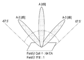
도 4a 내지 도 4c는 본 발명의 다양한 실시 예에 따른 어레이 안테나에서 형성되는 무선 전력 필드를 개념적으로 도시한다. 여기서 무선 전력 필드는 빔 포밍된, 즉 특정 방향으로 지향된 RF 웨이브를 의미한다.FIGS. 4A through 4C conceptually show a wireless power field formed in an array antenna according to various embodiments of the present invention. Where the wireless power field means an RF wave that is beamformed, i. E. Directed in a particular direction.
도 4a를 참조하면 무선 전력을 수신하는 전자장치가 한 개인 경우, 무선 전력 전송장치는 어레이 안테나에서 하나의 필드(filed)를 형성할 수 있다. 예컨대, 안테나 셀이 64개인 경우, 무선 전력 전송장치는 최대 64개의 셀이 하나의 무선 전력 수신 장치를 포커싱(focusing) 하도록 필드를 형성할 수 있다. 즉, 최대 64개의 셀에서 방사되는 RF 웨이브가 전자장치에서 가장 높은 진폭을 갖도록 필드를 형성할 수 있다.Referring to FIG. 4A, when there is one electronic apparatus for receiving wireless power, the wireless power transmission apparatus can form one field (filed) in the array antenna. For example, if there are 64 antenna cells, the wireless power transmission apparatus can form a field so that a maximum of 64 cells can focus one wireless power receiving apparatus. That is, a field can be formed such that the RF wave emitted from up to 64 cells has the highest amplitude in the electronic device.
설명의 편의를 위해 구 좌표계의 쎄타(Theta) 방향만 고려하며, 파이(Pi) 방향은 0~360도로 변위되는 것을 가정한다. For convenience of explanation, it is assumed that only the Theta direction of the spherical coordinate system is considered, and the Pi direction is displaced from 0 to 360 degrees.
도 4b를 참조하면 무선 전력을 수신하는 전자장치가 두 개인 경우, 무선 전력 전송장치는 어레이 안테나에서 2 개의 필드를 형성할 수 있다. 예컨대 안테나 셀이 64개인 경우 무선 전력 전송장치는 최대 32개의 셀이 필드를 생성하도록 제어할 수 있다. 예를 들어 32개의 셀이 제 1 필드를 형성하고, 나머지 32개의 셀이 제 2 필드를 형성하도록 할 수 있다. 제 1 필드는 -67.5도에서 0도 범위 내에서 형성되고, 제 2 필드는 0도에서 +67.5도 범위 내에서 형성될 수 있다.Referring to FIG. 4B, when there are two electronic apparatuses receiving wireless power, the wireless power transmission apparatus can form two fields in the array antenna. For example, if there are 64 antenna cells, the wireless power transmission apparatus can control to generate fields of up to 32 cells. For example, 32 cells may form the first field and the remaining 32 cells may form the second field. The first field may be formed within a range of -67.5 degrees to 0 degrees, and the second field may be formed within a range of 0 degrees to +67.5 degrees.
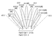
도 4c를 참조하면 무선 전력을 수신하는 전자장치가 세 개인 경우, 무선 전력 전송장치는 어레이 안테나에서 3 개의 필드를 형성할 수 있다. 예컨대 안테나 셀이 64개인 경우 최대 22개의 셀을 이용하여 필드를 생성하도록 제어할 수 있다. 예를 들어, 제 1 필드에에 22개의 셀, 제 2 필드에 22개의 셀, 그리고 제 3 필드에 22개의 안테나 셀이 할당될 수 있다. 제 1 필드는 -67.5도 내지 -22.5도 범위에서 형성되고, 제 2 필드는 는 -22.5도 내지 +22.5도 범위에서 형성되고, 제 3 필드는 +22.5도 내지 +67.5도 범위에서 방사될 수 있다.Referring to FIG. 4C, when there are three electronic devices receiving wireless power, the wireless power transmission apparatus can form three fields in the array antenna. For example, when 64 antenna cells are used, it is possible to control to generate fields using up to 22 cells. For example, 22 antenna cells may be allocated to the first field, 22 cells to the second field, and 22 antenna cells to the third field. The first field is formed in the range of -67.5 degrees to -22.5 degrees, the second field is formed in the range of -22.5 degrees to +22.5 degrees, and the third field is formed in the range of +22.5 degrees to +67.5 degrees .
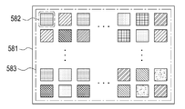
도 5a 내지 도 5c는 무선 전력 전송장치가 어레이 안테나를 구성하는 셀의 위상을 제어하여 복수의 전자장치로 전력을 전송하는 예를 도시한다. 여기서 각각의 셀은 서브 RF 웨이브를 방사하는 안테나이며, 서브 RF 웨이브들이 무선 충전의 대상인 전자 장치의 위치에서 가장 높은 진폭을 갖도록 보강 간섭을 일으켜, 전자장치로 무선 전력을 전송할 수 있다. 이를 위해, 무선 전력 전송장치의 제어부는 각각의 셀에서 방사되는 서브 RF 웨이브의 위상 및 진폭 중 적어도 하나를 제어할 수 있다.5A to 5C show examples in which a wireless power transmission apparatus controls the phase of a cell constituting an array antenna to transmit power to a plurality of electronic devices. Where each cell is an antenna that emits a sub RF wave and can transmit radio power to the electronic device by causing constructive interference so that the sub RF waves have the highest amplitude at the location of the electronic device that is the object of wireless charging. To this end, the control unit of the wireless power transmission apparatus can control at least one of the phase and the amplitude of the sub RF wave emitted from each cell.
도 5a를 참조하면 어레이 안테나(581) 및 어레이 안테나(581)을 구성하는 복수의 셀(583)이 도시되어 있다. 제어부는 어레이 안테나(581)를 구성하는 각각의 셀(582)에서 방사되는 서브 RF 웨이브의 위상 및 진폭 중 적어도 하나를 제어할 수 있다. 구체적으로, 무선 전력 전송장치의 제어부는 어레이 안테나(581)를 구성하는 복수의 셀(582) 각각에 공급되는 전력의 위상 및 진폭 중 적어도 하나를 제어하여 셀(582)에서 방사되는 서브 RF 신호의 크기 또는 위상을 변경할 수 있다. 5A, a plurality of
제어부는 각각의 셀에 대해 개별적으로 위상 및 진폭을 제어해야 하므로, 제어 해야 할 대상이 많아 연산량이 많고 제어 시간이 오래 걸릴 수 있다. 그러나, 각각의 셀이 개별적으로 제어되므로 다양한 크기의 무선 전력을 필요로 하는 복수의 무선전력 수신장치에 대해 무선 전력을 공급할 수 있는 장점이 있다. 또한 무선전력을 수신하는 전자장치의 개수 및 위치가 변경되는 경우에도 유연하게 대응할 수 있는 장점이 있다. Since the control unit must individually control the phase and the amplitude for each cell, there are many objects to be controlled, so that the calculation amount is large and the control time may be long. However, since each cell is individually controlled, there is an advantage that wireless power can be supplied to a plurality of wireless power receiving apparatuses requiring various sizes of wireless power. There is also an advantage that it is possible to cope flexibly when the number and location of electronic devices receiving wireless power are changed.
예를 들면 무선전력을 수신하는 전자장치가 2개인 경우 제어부는 무선전력 수신장치의 위치에 따라 각각의 셀을 제어하여 무선 전력에 대응하는 RF 웨이브가 각각의 전자장치를 타겟팅(targeting) 하도록 RF 웨이브를 방사할 수 있다.For example, if there are two electronic devices that receive wireless power, the control unit controls each cell according to the position of the wireless power receiving device so that an RF wave corresponding to the wireless power targets each electronic device. .
도 5b를 참조하면 어레이 안테나(584), 복수의 셀(586) 및 그룹(585)이 도시되어 있다.Referring to FIG. 5B, an
무선 전력 전송장치는 복수의 셀을 동적으로 조합하여 복수의 그룹으로 그룹핑 할 수 있다. 즉, 각 그룹에 포함되는 셀의 개수는 다를 수 있다.The wireless power transmission apparatus can dynamically combine a plurality of cells into a plurality of groups. That is, the number of cells included in each group may be different.
무선 전력 전송장치의 제어부는 무선전력을 수신하는 전자장치의 개수, 위치 및 전자장치가 필요로 하는 전력량에 따라 복수의 셀을 동적으로 그룹핑 하여 복수의 그룹을 생성할 수 있다. 각 그룹에 포함되는 셀의 개수 및 조합은 무선 전력을 수신하는 전자장치의 위치, 전자장치가 배치된 방향 및 전자장치가 필요로 하는 전력량에 따라 다를 수 있다. 무선 전력 전송장치는 각 그룹을 하나의 단위로 제어할 수 있다. 즉, 무선 전력 전송장치는 동일한 그룹에 속한 셀에 대해 위상 및 진폭을 일괄적으로 제어할 수 있다. 무선 전력 전송장치는 하나의 셀 그룹이 하나의 타겟(전자장치)에 무선 전력을 전송하도록 그룹에 포함된 각 셀에서 방사되는 서브 RF 신호의 크기 및 위상을 제어할 수 있다. 즉, 충전하고자 하는 전자 장치의 위치 및 거리 중 적어도 하나에 기반하여 그룹에 포함된 각각의 셀로 공급되는 전력의 위상 및 크기 중 적어도 하나를 조정할 수 있다. 이 때 각 그룹에 속하는 셀의 개수는 충전하려는 대상 전자 장치의 개수, 방향, 거리, 요구 전력량 등에 따라 각 그룹마다 다를 수 있다.The control unit of the wireless power transmission device can dynamically group a plurality of cells according to the number, position, and amount of power required by the electronic device to receive wireless power, thereby generating a plurality of groups. The number and combination of cells included in each group may vary depending on the location of the electronic device receiving the wireless power, the direction in which the electronic device is placed, and the amount of power required by the electronic device. The wireless power transmission apparatus can control each group in one unit. That is, the wireless power transmission apparatus can collectively control the phase and the amplitude for the cells belonging to the same group. The wireless power transmission apparatus can control the size and phase of the sub RF signal emitted in each cell included in the group so that one cell group transmits wireless power to one target (electronic device). That is, at least one of the phase and the magnitude of the power supplied to each cell included in the group can be adjusted based on at least one of the position and the distance of the electronic device to be charged. At this time, the number of cells belonging to each group may be different for each group depending on the number, direction, distance, required power amount, and the like of the electronic devices to be charged.
예를 들면 무선 전력 전송장치가 64개의 셀을 제 1 그룹, 제 2 그룹, 제 3 그룹 및 제 4 그룹으로 그룹핑 하는 경우, 무선 전력 전송장치는 제 1 그룹에는 20개의 셀을 할당하고, 제 2 그룹에는 18개의 셀을 할당하고, 제 3 그룹에는 16개의 셀을 할당하고, 제 4 그룹에는 10개의 셀을 할당할 수 있다. 즉, 무선 전력 전송장치는 무선 전력을 수신하는 전자장치의 위치, 배치 방향 및 필요로 하는 전력량에 따라 각 그룹에 할당되는 셀의 개수를 다르게 조정할 수 있다.For example, when a wireless power transmission apparatus groups 64 cells into a first group, a second group, a third group, and a fourth group, the wireless power transmission apparatus allocates 20 cells to the first group, 18 cells can be allocated to the group, 16 cells can be allocated to the third group, and 10 cells can be allocated to the fourth group. That is, the wireless power transmission apparatus can adjust the number of cells allocated to each group differently according to the position, arrangement direction, and required power amount of the electronic device receiving the wireless power.
도 5c를 참조하면 어레이 안테나(587), 복수의 셀(589) 및 그룹(588)이 도시되어 있다.Referring to FIG. 5C, an
무선 전력 전송장치는 복수의 셀을 동일한 개수로 조합하여 하나의 그룹으로 그룹핑 할 수 있다. 즉, 각 그룹에 포함되는 셀의 개수는 동일하다. 제어부는 무선전력 수신장치의 개수, 무선전력 수신장치의 위치 정보 및 무선전력 수신장치가 필요로 하는 전력량에 따라 복수의 셀을 동일한 개수로 조합하여 그룹을 생성할 수 있다. 또한, 제어부는 각 그룹에 포함된 셀로 공급되는 전력량을 조절하여 무선 전력 수신장치로 공급되는 전력량을 조정할 수 있다.The wireless power transmission apparatus can group a plurality of cells into one group by combining the same number of cells. That is, the number of cells included in each group is the same. The control unit may generate a group by combining a plurality of cells in the same number according to the number of wireless power receiving devices, the location information of the wireless power receiving device, and the amount of power required by the wireless power receiving device. In addition, the controller may adjust the amount of power supplied to the cells included in each group to adjust the amount of power supplied to the wireless power receiving apparatus.
예를 들면 무선 전력을 수신하는 전자장치의 개수가 4개이고, 어레이 안테나를 구성하는 셀의 개수가 64개인 경우, 무선 전력 전송장치는 64개의 셀을 4개의 그룹으로 그룹핑할 수 있으며, 각 그룹에 포함되는 셀의 개수는 16개로 동일하다. 즉 무선 전력 전송장치는 각각의 전자장치에 대해 16개의 셀을 할당할 수 있다. 이후, 무선 전력을 수신하는 전자장치의 배치 위치가 변경되는 경우, 무선 전력 전송 장치는 그룹에 포함되는 셀의 개수를 변경하지 않고, 각각의 그룹이, 대응하는 전자장치를 타겟팅(targeting)할 수 있도록 필드를 생성할 수 있다. 여기서 ‘전자장치를 타겟팅’ 한다는 의미는 전자장치를 지향하는 빔을 포밍하도록 필드를 생성하는 것을 의미할 수 있다.For example, when the number of electronic devices receiving radio power is four and the number of cells constituting the array antenna is 64, the radio power transmission apparatus can group 64 cells into four groups, The number of cells included is equal to 16. That is, the wireless power transmission device can allocate 16 cells for each electronic device. Thereafter, when the placement position of the electronic device receiving the wireless power is changed, the wireless power transmission device does not change the number of cells included in the group, and each group can target the corresponding electronic device Fields. Here, the term 'targeting electronic devices' may mean creating a field to form a beam that directs the electronic device.
도 6은 어레이 안테나를 구성하는 복수의 셀이 무선 전력을 전송하기 위해 그룹핑되는 예를 도시한다.6 shows an example in which a plurality of cells constituting the array antenna are grouped to transmit radio power.
도 6을 참조하면 어레이 안테나(600) 및 복수의 전자장치(674, 675, 676)가 도시되어 있다. 어레이 안테나(600)는 복수의 셀(601 내지 664)을 포함할 수 있다. 복수의 셀(601 내지 664)은 예컨대 3개의 그룹(671, 672, 673)으로 그룹핑될 수 있다.6, an
각각의 전자장치가 요구하는 전력의 크기는 전자장치 A > 전자장치 B > 전자장치 C 의 순으로 상정할 수 있다. 무선 전력 전송장치는 통신부를 통해 각 전자장치(674, 675, 676)가 전송하는 정보를 수신할 수 있다. 전자장치가 전송하는 정보는 예컨대 전자장치의 배터리 잔량, 충전모드, 전자장치가 수신한 무선 전력량, 전자장치가 필요로 하는 무선 전력량 및 전자장치의 ID 정보 등을 포함할 수 있다. 실시 형태에 따라 전자장치는 자신의 위치 정보를 무선 전력 전송장치로 전송할 수 있다. The magnitude of the power required by each electronic device can be estimated in the order of electronic device A> electronic device B> electronic device C. The wireless power transmission device can receive information transmitted by each
무선 전력 전송장치는 무선 전력을 수신하는 전자장치를 검출하기 위해 전자기파를 방사할 수 있다. 무선 전력 전송장치가 전자장치를 검출하는 방법에 대해서는 상술하였으므로 설명을 생략한다.The wireless power transmission device may emit electromagnetic waves to detect an electronic device that receives wireless power. Since the method of detecting the electronic device by the wireless power transmission device has been described above, the description is omitted.
무선 전력 전송장치는 전자장치로부터 수신한 정보에 기초하여 무선 전력을 수신하는 전자장치의 위치 및 무선 전력을 수신하는 전자장치의 개수를 결정하고, 결정된 전자장치의 개수에 기초하여 셀 안테나 그룹을 생성할 수 있다.The wireless power transmission device determines the location of the electronic device receiving the wireless power and the number of electronic devices receiving the wireless power based on the information received from the electronic device, and generates a cell antenna group based on the determined number of electronic devices can do.
예를 들면 무선 전력 전송장치는 전자장치(674, 675, 676)가 전송하는 ID 정보를 수신하고, 수신된 ID 정보로부터 무선전력을 수신하는 전자장치가 3개인 것으로 결정할 수 있다. For example, the wireless power transmission device may receive the ID information transmitted by the
무선 전력 전송장치는 전자장치의 개수가 결정되면 전자장치의 개수에 기초하여 그룹을 생성할 수 있다. 예를 들면 전자장치의 개수가 3개인 경우, 무선 전력 전송장치는 어레이 안테나(600)에 포함된 복수의 셀(601 내지 664)을 복수 개 조합하여 3개의 그룹을 생성할 수 있다.The wireless power transmission device may create a group based on the number of electronic devices once the number of electronic devices is determined. For example, when the number of electronic devices is three, the wireless power transmission apparatus can generate three groups by combining a plurality of
또한 무선 전력 전송장치는 전자장치가 전송하는 무선 전력 수신과 관련된 정보 또는 전자장치가 필요로 하는 전력량에 대한 정보를 수신하고 이에 따라 그룹에 포함되는 셀의 개수를 결정할 수 있다. 예를 들면, 전자장치(674 내지 676)가 필요로 하는 전력량의 크기가 전자장치 A(674) > 전자장치 B(675) > 전자장치 C(676)의 순이면, 무선 전력 전송장치는 전자장치 A(674)에 대해 셀 그룹 A(671)을 생성하고, 전자장치 B(675)에 대해 셀 그룹 B(672)를 생성하고, 전자장치 C(676)에 대해 셀 그룹 C(673)를 각각 생성할 수 있다. 그룹 A(671)에는 32개의 셀이 할당되어, 할당된 셀들에 입력되는 전력의 크기 및 위상 중 적어도 하나를 제어하여 방사되는 서브 RF 웨이브들이 보강 간섭을 일으켜 전자장치 A(674)을 포커싱하는 필드를 생성할 수 있다. 그룹 B(672)에는 24개의 셀이 할당되어, 할당된 셀들에 입력되는 전력의 크기 및 위상 중 적어도 하나를 제어하여 방사되는 서브 RF웨이브들이 보강 간섭을 일으켜 전자장치 B(675)를 포커싱하는 필드를 생성할 수 있다. 그룹 C(673)에는 8개의 셀이 할당되어, 할당된 셀들에 입력되는 전력의 크기 및 위상 중 적어도 하나를 제어하여 방사되는 서브 RF 웨이브들이 보강 간섭을 일으켜 전자장치 C(676)을 포커싱하는 필드를 생성할 수 있다. The wireless power transmission apparatus may also receive information related to reception of wireless power transmitted by the electronic device or information on the amount of power required by the electronic device, and thus determine the number of cells included in the group. For example, if the amount of power required by the
무선 전력 전송장치의 제어부는 전자 장치에 가장 좋은 효율로 전력을 전송할 수 있는 셀 안테나의 위치를 고려하여 그룹을 설정할 수 있다. 예를 들어, 전자 장치 A(674)에 무선 전력을 전송하기 위한 그룹 설정 시 전자 장치 A(674)와 가깝게 위치하는 셀들, 어레이 안테나의 왼쪽부분에 위치하는 셀을 선택하여 셀 그룹 A(671)에 할당 할 수 있다.The controller of the wireless power transmission apparatus can set the group considering the position of the cell antenna capable of transmitting power with the best efficiency to the electronic device. For example, in the group setting for transmitting the radio power to the
도 7은 무선 전력 전송장치가 하나의 전자장치를 충전하는 도중에 새로운 전자장치가 검출되어 그룹을 재생성 하는 예를 도시한다.7 shows an example in which a new electronic device is detected and a group is regenerated while the wireless power transmission device is charging one electronic device.
도 7을 참조하면 어레이 안테나(600), 전자장치 A(705) 및 전자장치 B(707)가 도시되어 있다. 여기서, 전자장치 B(707)는 전자장치 A(705)가 충전되는 도중에 추가로 검출되는 것으로 가정하고 설명한다.7,
어레이 안테나(600)는 복수의 셀(601 내지 664)을 포함할 수 있으며, 셀의 개수는 64개로 될 수 있다. 각각의 셀(601 내지 664)은 서브 RF 웨이브를 방사할 수 있으며, 서브 RF 웨이브는 무선 전력에 해당한다.The
무선 전력 전송장치가 전자장치(705)를 검출하고 전자장치(705)를 충전하는 경우, 어레이 안테나(600)를 구성하는 모든 셀(601 내지 664)이 방사하는 서브 RF 웨이브를 이용하여 전자장치(705)를 포커싱 하는 필드를 형성할 수 있다. 즉, 무선 전력 전송장치는 모든 셀(601 내지 664)이 전자장치(705)에게 포커싱되는 필드를 형성하도록 셀(601 내지 664)에서 방사되는 무선 전력의 위상 및 진폭 중 적어도 하나를 제어할 수 있다.When the wireless power transmission apparatus detects the
이후에 새로운 전자장치 B(707)가 추가로 검출되면 무선 전력 전송장치는 전자장치 A(705) 및 전자장치 B(707)가 전송한 정보에 기초하여 그룹 A(701) 및 그룹 B(703)를 생성할 수 있다. 예를 들면, 무선 전력 전송장치가 각 전자장치(705, 707)로부터 수신한 정보는 각 전자장치(705, 707)에서 필요로 하는 무선 전력량을 포함할 수 있다. Subsequently, when a new
전자장치 A(705)가 필요로 하는 전력이 전자장치 B(707)가 필요로 하는 전력보다 많은 경우 무선 전력 전송장치는 전자장치 A(705)에게 더 많은 셀을 할당하여 그룹 A(701)를 생성할 수 있다. 예를 들면 그룹 A(701)은 40개의 셀을 포함하고, 그룹 B(703)는 24개의 셀을 포함할 수 있다. If the power required by the
무선 전력 전송장치는 그룹 A(701) 및 그룹 B(703)를 생성하면서 기존에 충전중인 전자장치 A(705)의 충전 전력 감쇄 등에 미치는 영향을 최소화 시키기 위해 생성된 그룹 A,B (701, 703)에 포함된 셀에서 방사되는 전자기파의 위상 및 진폭을 점차적으로 변경시킬 수 있다.The wireless power transmission apparatus generates the
또한 전자 장치의 수신 전력, 긴급 요청 등의 상황을 판단하여 기존 충전 중인 전자 장치의 충전을 위한 그룹화를 해제하여, 기존의 전력 전송을 중단한 이후에 재 그룹화를 진행하여 전자장치 A(705) 및 전자장치 B(707)로 무선 전력을 전송할 수 있다.In addition, it is also possible to determine the status of the received power of the electronic device, the urgent request, and the like to release the grouping for charging the existing electronic devices to be recharged, And may transmit wireless power to
실시 형태에 따라 무선 전력 전송장치는 기존에 충전 중이던 전자장치 B(705)로 전송되는 무선 전력량을 균일하게 유지시키기 위해 그룹 A(701)에 포함된 복수의 셀로 공급되는 전력량을 증가 시킬 수 있다.The wireless power transmission apparatus can increase the amount of power supplied to a plurality of cells included in the
예를 들면, 무선 전력 전송장치는 전자장치 A(705)를 충전중인 상태에서 새로운 전자장치 B(707)가 검출되면, 무선 전력 전송장치는 복수의 셀을 조합하여 그룹 A,B(701, 703)를 생성하고, 그룹 A,B(701, 703)에 포함된 셀로 공급되는 전력의 양을 조절할 수 있다.For example, when the wireless power transmission apparatus detects a new
도 8은 무선 전력 전송장치가 두 개의 전자장치를 충전하는 도중에 또 다른 전자장치가 검출되어 셀 그룹을 재생성 하는 예를 도시한다.Fig. 8 shows an example in which another electronic device is detected while a wireless power transmission device is charging two electronic devices to regenerate a group of cells.
도 8을 참조하면 어레이 안테나(600), 전자장치 A(705), 전자장치 B(707) 및 전자장치 C(708)가 도시되어 있다. 여기서 전자장치 C(708)는 전자장치 A(705)와 전자장치 B(707)이 충전되는 도중에 추가로 검출된 것으로 가정하고 설명한다.8, an
어레이 안테나(600)는 복수의 셀(601 내지 664)을 포함할 수 있다. 예를 들면 셀의 개수는 64개로 될 수 있다. 각각의 셀(601 내지 664)은 서브 RF 웨이브를 방사할 수 있으며 서브 RF 웨이브는 무선 전력에 해당한다.The
무선 전력 전송장치는 무선 전력을 수신하는 전자장치가 추가로 검출되는 경우, 기존의 그룹을 해체하고 새로운 그룹을 생성할 수 있다.The wireless power transmission device can disassemble an existing group and create a new group when an electronic device receiving wireless power is detected further.
예를 들면 무선 전력 전송장치가 두 개의 전자장치(705, 707)을 검출하여 충전하는 경우, 무선 전력 전송장치는 전자장치 A(705) 및 전자장치 B(707)가 전송한 정보에 기초하여 그룹 A(701) 및 그룹 B(703)를 생성할 수 있다. For example, when the wireless power transmission device detects and charges two
무선 전력 전송장치가 두 개의 전자장치 A,B(705, 707)를 충전하는 도중에 새로운 전자장치 C(708)를 검출하는 경우, 무선 전력 전송장치는 기존에 생성된 그룹 A,B(701, 703)를 해체하고 셀을 새롭게 조합하여 새로운 그룹 C,D,E(821, 822, 823)를 생성할 수 있다.When the wireless power transmission device detects a new
무선 전력 전송장치는 전자장치 A,B,C(705, 707, 708)로부터 수신된 정보에 기초하여 그룹 C,D,E(821, 822, 823)를 생성할 수 있다. 각 그룹에 포함되는 셀의 개수는 전자장치가 전송한 정보에 기초하여 결정될 수 있다. 예를 들면, 전자장치가 필요로 하는 전력량에 따라 셀의 개수가 결정될 수 있다. 전자장치가 필요로 하는 전력량이 큰 경우에는 많은 수의 셀이 할당되고 전력량이 작은 경우에는 상대적으로 적은 수의 셀이 할당될 수 있다.The wireless power transmission device may generate groups C, D, E (821, 822, 823) based on information received from electronic devices A, B,
무선 전력 전송장치는 전자장치의 충전 모드에 따라 그룹에 포함되는 셀의 개수가 결정될 수 있다. 예를 들면, 전자장치 A(705)가 급속 충전 모드이고 전자장치 B(707)가 일반 충전 모드인 경우 무선 전력 전송장치는 전자장치 A(705)에 대응하는 그룹 C(821)에 상대적으로 많은 개수의 셀을 할당할 수 있다. 전자장치의 충전 모드는 사용자에 의해 결정될 수 있으며, 결과적으로 무선 전력 전송장치는 사용자 입력에 기초하여 그룹에 포함되는 셀의 개수를 결정하고, 결정된 셀들을 이용하여 그룹을 생성할 수 있다.The wireless power transmission apparatus can determine the number of cells included in the group according to the charging mode of the electronic device. For example, if the
무선 전력 전송장치는 전자 장치에 포함된 배터리의 잔량 정보에 기초하여 그룹을 생성할 수 있다. 구체적으로 무선 전력 전송장치는 배터리의 잔량이 많은 전자장치에는 배터리의 잔량이 적은 전자장치에 비해 상대적으로 적은 수의 셀을 할당하여 그룹을 생성할 수 있다. 즉, 잔량이 더 적은 전자장치에 더 많은 셀의 할당을 통해 단위 시간당 더 많은 전력을 보낼 수 있다. 예를 들면, 전자장치 B(707)의 배터리 잔량이 30%이고, 전자장치 C(708)의 잔량이 80%인 경우, 무선 전력 전송장치는 그룹 D(822)에 24개의 셀을 할당하고 그룹 C(823)에 8개의 셀을 할당한다.The wireless power transmission device can generate the group based on the remaining amount information of the battery included in the electronic device. Specifically, a wireless power transmission apparatus can generate a group by assigning a relatively small number of cells to an electronic device having a large battery level as compared to an electronic device having a small battery level. That is, it is possible to send more power per unit time through the allocation of more cells to the electronic device with the smaller remaining amount. For example, if the remaining battery level of the
무선 전력 전송장치는 어레이 안테나(600)에서 전자장치 A,B,C(705, 707, 708)까지의 거리에 따라 그룹을 생성할 수 있다. 예를 들면, 어레이 안테나(600)로부터 전자장치 A(705)까지의 거리는 100cm, 전자장치 B(707)까지의 거리는 80cm, 전자장치 C(708)까지의 거리는 70cm 이라고 가정할 때, 무선 전력 전송장치는 전자장치 A(705)에 대응하는 그룹 C(821)에 32개의 셀을 할당하고, 전자장치 B(707)에 대응하는 그룹 D(822)에는 24개의 셀을 할당하고, 전자장치 C(708)에 대응하는 그룹 E(823)에는 8개의 셀을 할당할 수 있다.The wireless power transmission apparatus can generate a group according to the distance from the
무선 전력 전송장치는 새로운 그룹 C,D,E(821, 822, 823)를 생성하면서 셀에서 방사되는 무선 전력량이 서서히 변경되도록 위상 및 진폭을 제어하여 새로운 그룹 C,D,E(821, 822, 823)에 포함되는 셀에서 무선 전력이 방사되도록 할 수 있다. 이에 따라 기존에 충전 중이던 전자장치 A,B(705, 707)의 충전 동작이 끊어지지 않고 자연스럽게 새로운 그룹에 포함된 셀에 의해 충전 동작이 연속적으로 수행될 수 있다.The wireless power transmission apparatus controls the phase and amplitude to gradually change the amount of radio power radiated from the cell while generating a new group C, D, E (821, 822, 823) The wireless power may be radiated in the cells included in the first and
또한 전자 장치의 수신 전력, 긴급 요청 등의 상황을 판단하여 기존 충전 중인 전자 장치 A, B(705, 707)를 위한 기존 셀 그룹(701, 703)을 해제하여 기존의 전력 전송을 중단한 이후, 새롭게 생성된 셀 그룹(821, 822, 823)을 통해 전자장치 A(705), B(707) 및 전자장치 C(708)로 무선 전력을 전송할 수 있다.In addition, after the existing
무선 전력 전송장치가 각각의 셀에 전력을 공급하는 방식은 패시브 타입(passive type) 및 액티브 타입(active type)이 있다. The manner in which the wireless power transmission apparatus supplies power to each cell is of a passive type and an active type.
패시브 타입에서 셀을 동적으로 할당하는 경우, 무선 전력 전송장치는 전력 분배기를 이용하여 각 셀에 동일한 전력을 인가한다. 이 경우, 그룹에 할당된 셀의 개수와 위상 제어각에 의해 필드 폭이 달라질 수 있다.When dynamically allocating cells in a passive type, the wireless power transmission apparatus applies the same power to each cell using a power divider. In this case, the field width may vary depending on the number of cells allocated to the group and the phase control angle.
패시브 타입에서 어레이 안테나에 포함된 전체 셀이 하나의 전자장치에게 전력을 공급하고 있는 상황에서 다른 전자장치가 충전 영역 안으로 들어오면 무선 전력 전송장치는 무선 전력 전송장치의 개수에 맞춰 셀을 균등하게 분할하여 그룹을 생성할 수 있다. 이로 인해 각각의 전자장치에 충분한 전력이 공급되지 않는 경우 무선 전력 수신장치는 전력 증폭기의 출력을 증가시켜 충분한 전력을 셀에 공급할 수 있다. 다시 말해서 패시브 방식에서는 전력 증폭기에서 동일 전력을 공급하는 경우 각 셀에 공급되는 전력은 동일하게 분배될 수 있으며, 각각의 전자장치로 공급되는 무선 전력량은 그룹화된 셀의 개수에 따라 달라질 수 있다.In the passive type, when all the cells included in the array antenna are supplying power to one electronic device and another electronic device enters the charging area, the wireless power transmission device divides the cell equally according to the number of the wireless power transmission devices To create a group. As a result, when not enough power is supplied to each electronic device, the wireless power receiving device can increase the output of the power amplifier and supply sufficient power to the cell. In other words, in the passive scheme, when the same power is supplied from the power amplifier, the power supplied to each cell can be equally distributed, and the amount of radio power supplied to each electronic device can be changed according to the number of the grouped cells.
또한 이 상태에서 다른 전자장치가 추가된 경우 무선 전력 전송장치는 다시 셀을 분할할 수 있으며, 무선 전력 전송장치가 전력 증폭기의 전력을 바꾸지 않을 경우, 기존에 충전 중이던 전자장치에게 전송되는 무선 전력량은 추가된 전자장치에게 할당된 셀의 개수만큼 줄어들 수 있다. 이를 보상하기 위해 무선 전력 전송장치는 전력 증폭기의 출력을 제어할 수 있으며, 이로 인해 충전 동작이 중단되지 않을 수 있다.If another electronic device is added in this state, the wireless power transmission device can divide the cell again. If the wireless power transmission device does not change the power of the power amplifier, the amount of wireless power to be transmitted to the electronic device It can be reduced by the number of cells allocated to the added electronic device. To compensate for this, the wireless power transmission device can control the output of the power amplifier, which may prevent the charging operation from being interrupted.
액티브 타입(active type)에서는 무선 전력 전송장치가 각 셀의 전력을 개별적으로 제어할 수 있다. 무선 전력 전송장치는 셀을 동적으로 그룹핑하고 무선 전력을 수신하는 전자장치가 수신한 무선 전력량에 대한 정보를 전자장치로부터 수신하여 각 셀의 전력량을 제어할 수 있다. 액티브 타입에서 어레이 안테나에 포함된 전체 셀이 하나의 전자장치에게 전력을 공급하고 있는 상황에서 다른 전자장치가 충전 영역 안으로 들어오면 무선 전력 전송장치는 무선 전력 전송장치의 개수에 맞춰 셀을 균등하게 분할하여 그룹을 생성할 수 있다. 이로 인해 각각의 전자장치에 충분한 전력이 공급되지 않는 경우 무선 전력 수신장치는 전력 증폭기의 출력을 증가시켜 각각의 셀에 충분한 전력을 공급할 수 있다. 각각의 전자장치로 공급되는 무선 전력량은 그룹화된 셀의 개수에 따라 달라질 수 있다.In the active type, the wireless power transmission apparatus can individually control the power of each cell. The wireless power transmission device can dynamically group the cells and receive information from the electronic device about the amount of wireless power received by the electronic device receiving the wireless power to control the amount of power of each cell. In the active type, when all the cells included in the array antenna are supplying power to one electronic device, when the other electronic device enters the charging area, the wireless power transmission device divides the cell equally according to the number of the wireless power transmission devices To create a group. As a result, if sufficient power is not supplied to each electronic device, the wireless power receiving apparatus can increase the output of the power amplifier and supply sufficient power to each cell. The amount of radio power supplied to each electronic device may vary depending on the number of grouped cells.
또한 이 상태에서 다른 전자장치가 추가된 경우 무선 전력 전송장치는 다시 셀을 분할할 수 있으며, 무선 전력 전송장치가 전력 증폭기의 전력을 바꾸지 않을 경우, 기존에 충전 중이던 전자장치에게 전송되는 무선 전력량은 추가된 전자장치에게 할당된 셀의 개수만큼 줄어들 수 있다. 이를 보상하기 위해 무선 전력 전송장치는 각 셀에 공급되는 전력량을 제어할 수 있으며, 이로 인해 충전 동작이 중단되지 않을 수 있다.If another electronic device is added in this state, the wireless power transmission device can divide the cell again. If the wireless power transmission device does not change the power of the power amplifier, the amount of wireless power to be transmitted to the electronic device It can be reduced by the number of cells allocated to the added electronic device. In order to compensate for this, the wireless power transmission apparatus can control the amount of power supplied to each cell, so that the charging operation may not be interrupted.
무선 전력 전송장치는 무선 전력을 수신하는 전자장치의 개수가 변경되는 경우 충전 우선순위를 결정하고 우선순위에 따라 새롭게 그룹을 형성할 수 있다. 우선순위는 전자장치로부터 수신된 정보에 기초하여 결정될 수 있다. 구체적으로 전자장치의 배터리 잔량, 충전 모드가 급속 모드인지 일반 모드인지에 따라 우선순위가 결정될 수 있다.The wireless power transmission device may determine the charging priority and form a new group according to the priority when the number of electronic devices receiving the wireless power is changed. The priority may be determined based on information received from the electronic device. Specifically, the priority level can be determined according to whether the battery remaining amount of the electronic device and the charging mode are the rapid mode or the normal mode.
예를 들면, 무선 전력 전송장치가 전자장치를 충전하는 도중에 새로운 전자장치가 검출되는 경우, 무선 전력 전송장치는 새롭게 추가된 전자장치로부터 정보를 수신하고, 수신한 정보에 기초하여 기존 충전중인 전자장치와의 우선순위를 결정할 수 있다. 새롭게 추가된 전자장치의 충전 모드가 ‘급속 모드’인 경우, 무선 전력 전송장치는 새롭게 추가된 전자장치에게 더 많은 셀을 할당하도록 그룹을 생성하거나 또는 상기 그룹에 포함된 셀로 공급되는 전력을 높일 수 있다. For example, if a new electronic device is detected while the wireless power transmission device is charging the electronic device, the wireless power transmission device receives the information from the newly added electronic device and, based on the received information, Can be determined. If the charging mode of the newly added electronic device is a 'rapid mode', the wireless power transmission device can generate a group to allocate more cells to the newly added electronic device, or to increase the power supplied to the cells included in the group have.
한편, 무선 전력 전송장치가 최대 파워로 전자장치를 충전하는 도중에 새로운 전자장치가 검출되는 경우, 무선 전력 전송장치는 새롭게 추가된 전자장치로부터 정보를 수신하여 현재 충전중인 전자장치와의 우선순위를 결정하고, 우선순위에 따라 새로운 그룹을 생성할 수 있다.On the other hand, when a new electronic device is detected while the wireless power transmission device is charging the electronic device with the maximum power, the wireless power transmission device receives the information from the newly added electronic device and determines the priority with respect to the currently charged electronic device , And a new group can be created according to the priority.
예를 들면, 무선 전력 전송장치가 전자장치 A(705)를 최대 파워로 충전하는 중에 새로운 전자장치 B, C(707, 708)를 검출한 경우, 무선 전력 전송장치는 전자장치 A, B, C(705, 707, 708)로부터 수신된 정보에 기초하여 전자장치 A, B, C(705, 707, 708)간에 우선순위를 결정할 수 있다. 무선 전력 전송장치는 우선 순위에 따라 새로운 그룹(821, 822, 823)을 생성하거나 또는 전자장치 A, B, C(705, 707, 708)의 충전 순서를 결정할 수 있다. 우선순위가 전자장치 A(705) > 전자장치 B(707) > 전자장치 C(708)의 순으로 결정되면 무선 전력 전송장치는 전자장치 A(705)를 가장 먼저 충전하고, 전자장치 A(705)의 충전이 완료된 이후에 전자장치 B, C(707, 708)를 충전하기 위해 새로운 그룹을 생성할 수 있다. 즉, 무선 전력 전송장치는 충전 우선 순위가 빠른 전자장치를 충전하고, 상기 전자장치의 충전이 완료될 때까지, 새로운 그룹의 생성을 보류할 수 있다.For example, if a wireless power transmission device detects a new electronic device B, C (707, 708) while charging the
도 9는 본 개시의 실시예에 따른 무선 전력 전송장치가 무선전력을 수신하는 전자장치에 따라 어레이 안테나에 포함된 셀을 조합하여 그룹을 생성하고 제어하는 방법에 대한 흐름도이다.9 is a flow chart of a method of combining and combining groups of cells included in an array antenna according to an electronic device in which a wireless power transmission apparatus according to an embodiment of the present disclosure receives wireless power.
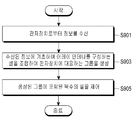
도 9를 참조하면, 무선 전력 전송장치는 단계 S901에서 전자장치로부터 정보를 수신한다. 상기 정보는 전자장치의 배터리 잔량, 충전 모드, 전자장치가 수신한 무선 전력량, 전자장치의 ID 정보 등을 포함할 수 있다. 충전 모드는 사용자 입력에 따라 설정될 수 있으며, 예를 들면 ‘급속 모드’ 및 ‘일반 모드’로 설정될 수 있다. 전자장치가 ‘급속 모드’로 설정되는 경우, 우선적으로 충전될 수 있으며, 무선 전력 전송장치는 ‘급속 모드’로 설정된 전자장치에게 상대적으로 많은 개수의 셀로 형성되는 그룹을 할당하여 더 큰 전력을 전송할 수 있다.Referring to Fig. 9, the wireless power transmission apparatus receives information from the electronic device in step S901. The information may include the battery level of the electronic device, the charging mode, the amount of radio power received by the electronic device, the ID information of the electronic device, and the like. The charging mode may be set according to the user input, and may be set to, for example, 'rapid mode' and 'normal mode'. When the electronic device is set to the 'rapid mode', it can be charged preferentially, and the wireless power transmission device allocates a group formed of a relatively large number of cells to the electronic device set in the 'rapid mode' .
무선 전력 전송장치는 단계 S903에서 수신된 정보에 기초하여 어레이 안테나를 구성하는 셀을 조합하여 전자장치에 대응하는 그룹을 생성할 수 있다. The wireless power transmission apparatus can combine the cells constituting the array antenna based on the information received in step S903 to generate a group corresponding to the electronic apparatus.
무선 전력 전송장치는 전자장치의 위치에서 서브 RF 웨이브들이 보강 간섭되도록, 셀 안테나들 각각에서 방사되는 서브 RF웨이브의 위상 및 진폭 중 적어도 하나를 제어하여, 전자장치로 빔 포밍 할 수 있다.The wireless power transmission device can control beamforming to an electronic device by controlling at least one of the phase and the amplitude of a sub RF wave emitted from each of the cell antennas so that the sub RF waves are constructively interfered at the location of the electronic device.
무선 전력 전송장치는 검출된 무선전력 수신장치의 방향 및 거리에 따라 셀들을 그룹핑할 수 있다. 무선 전력 전송장치는 상술한 바와 같이 무선전력 수신장치가 전송한 위치 정보 또는 위에서 설명한 방법을 이용하여 무선전력 수신장치의 방향 및 거리를 결정할 수 있다. 복수의 무선 전력 수신장치가 검출되면, 무선 전력 전송장치는 각 무선 전력 수신장치가 위치하는 방향 및 거리를 기초로 하여 어레이 안테나를 구성하는 복수의 셀들을 조합하여 각 무선 전력 수신장치에 대응하는 복수의 그룹을 형성할 수 있다.The wireless power transmission device can group the cells according to the direction and distance of the detected wireless power receiving device. The wireless power transmission apparatus can determine the direction and the distance of the wireless power receiving apparatus using the position information transmitted by the wireless power receiving apparatus or the method described above as described above. When a plurality of wireless power receiving apparatuses are detected, the wireless power transmitting apparatus combines a plurality of cells constituting the array antenna on the basis of a direction and a distance in which each wireless power receiving apparatus is located, Can be formed.
무선 전력 전송장치는 복수 개의 전자장치가 검출되는 경우, 검출된 전자장치의 개수에 맞춰 어레이 안테나를 복수의 그룹으로 그룹핑 할 수 있다. 예를 들면, 무선 전력 전송장치는 2 개의 전자장치가 검출되는 경우, 어레이 안테나를 2 개의 그룹으로 그룹핑할 수 있다.When a plurality of electronic devices are detected, the wireless power transmission device can group the array antennas into a plurality of groups according to the number of detected electronic devices. For example, a wireless power transmission device can group array antennas into two groups when two electronic devices are detected.
무선 전력 전송장치는 그룹이 생성되면, 단계 S905에서 생성된 그룹에 포함된 복수의 셀을 제어할 수 있다. 무선 전력 전송장치는 동일한 그룹에 포함된 셀이 대응하는 전자장치를 빔 포밍하도록 셀에서 방사되는 무선 전력의 위상 및 진폭 중 적어도 하나를 동시에 다른 위상 또는 진폭으로 변경되도록 일괄적으로 제어할 수 있다. When the group is created, the wireless power transmission apparatus can control a plurality of cells included in the group generated in step S905. The wireless power transmission apparatus can collectively control at least one of the phase and the amplitude of the wireless power radiated from the cell to simultaneously change to a different phase or amplitude so that the cells included in the same group beamform the corresponding electronic device.
도 10은 본 개시의 실시예에 따른 무선 전력 전송장치가 제1 전자장치를 무선 충전하는 중에 새로운 제2 전자장치를 추가로 검출하여, 각 전자 장치에 전력을 전송하기 위한 셀들의 그룹을 재생성하는 방법에 대한 흐름도이다.FIG. 10 is a flow chart of a method for wireless power transmission in accordance with an embodiment of the present disclosure further detecting a new second electronic device while wirelessly charging the first electronic device, regenerating a group of cells for transmitting power to each electronic device Fig.
도 10을 참조하면 무선전력 전송장치는 단계 S1001에서 제1 전자 장치에 대한 무선 충전 동작을 수행 중에 충전을 필요로 하는 제2 전자장치를 추가로 검출한다.Referring to FIG. 10, in step S1001, the wireless power transmission apparatus further detects a second electronic device that requires charging while performing a wireless charging operation for the first electronic device.
무선전력 전송장치가 전자장치를 검출하는 방법은 상술 하였으므로, 여기서는 생략한다.The method by which the wireless power transmission apparatus detects the electronic device has been described above, and therefore will not be described here.
무선 전력 전송장치는 제2 전자장치를 추가로 검출하는 경우, 단계 S1003에서 검출결과에 따라 기존의 그룹을 해체하고 새로운 그룹을 생성할 수 있다. 예를 들면, 무선 전력 전송장치가 그룹 A 및 그룹 B를 생성하여 제1 전자장치 및 제2 전자장치를 충전하는 중에 새로운 제3 전자장치가 검출되면, 무선 전력 전송장치는 그룹 A 및 그룹 B를 해체하고 세 개의 전자장치에 할당하기 위한 새로운 그룹 C, D, E를 생성할 수 있다.When the wireless power transmission apparatus further detects the second electronic device, the existing group can be disassembled and a new group can be created according to the detection result in step S1003. For example, if a new third electronic device is detected while the wireless power transmission device is generating groups A and B to charge the first electronic device and the second electronic device, then the wireless power transfer device will transmit group A and group B D, E for disassembly and assignment to the three electronic devices.
무선 전력 전송장치는 새로운 그룹이 생성되면 단계 S1005에서 새로운 그룹에 포함된 셀로 공급되는 전력량을 변경 시킬 수 있다. The wireless power transmission apparatus can change the amount of power supplied to the cells included in the new group in step S1005 when a new group is created.
예를 들면, 무선 전력 전송장치가 그룹 A 및 그룹 B에 대해 70의 전력량을 공급하다가 새로운 전자장치 C를 검출하고 새로운 그룹 C, D, E를 생성한 경우, 무선 전력 전송장치는 그룹 C, D, E에 대해 전력량을 100으로 증가시킬 수 있다. 또한 무선 전력 전송장치는 기존 그룹을 해체하고 새로운 그룹을 생성하면서 새로운 그룹에 포함된 셀에서 방사되는 전자기파의 위상 및 진폭을 점차적으로 변경시킴으로서 무선 전력 공급을 연속적으로 할 수 있다.For example, if the wireless power transmission device supplies 70 watts to group A and group B and detects a new electronic device C and generates new groups C, D, E, , The power amount for E can be increased to 100. In addition, the wireless power transmission apparatus can continuously supply the wireless power by disassembling the existing group and creating a new group by gradually changing the phase and amplitude of the electromagnetic waves radiated from the cells included in the new group.
또한 무선 전력 전송장치는 기존 그룹을 해체하면서 무선 전력 공급을 일시적으로 중단하고, 새로운 그룹을 생성하면서 무선 전력 공급을 재개할 수 있다.In addition, the wireless power transmission apparatus can temporarily suspend the wireless power supply while disassembling the existing group, and resume the wireless power supply while creating a new group.
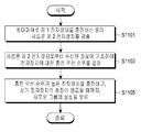
도 11은 본 개시의 실시예에 따른 무선 전력 전송장치가 최대 파워로 전자장치를 충전하는 중에 새로운 전자장치가 검출되는 경우 충전 우선 순위를 결정하는 방법에 대한 흐름도이다.11 is a flow diagram of a method for determining charge priorities when a new electronic device is detected while the wireless power transfer device charges the electronic device at full power according to an embodiment of the present disclosure;
도 11을 참조하면 무선 전력 전송장치는 단계 S1101에서 최대 파워로 제1 전자장치를 충전하는 중에 새로운 제2 전자장치를 검출하고, 무선 충전에 필요한 충전 모드 및 배터리 잔량과 같은 정보를 수신할 수 있다. 무선 전력 전송장치는 제2 전자장치를 검출하면, 단계 S1103에서 검출된 제2 전자장치로부터 수신된 정보에 기초하여 충전 우선 순위를 결정할 수 있다. 예를 들면 충전 우선 순위는 전자장치의 충전 모드, 각 전자장치의 배터리 잔량 등에 따라 결정될 수 있다.Referring to FIG. 11, the wireless power transmission apparatus can detect a new second electronic device while charging the first electronic device with the maximum power in step S1101, and receive information such as a charging mode and a remaining battery level necessary for wireless charging . Upon detecting the second electronic device, the wireless power transfer device may determine the charge priority based on the information received from the second electronic device detected in step S1103. For example, the charge priority may be determined according to the charge mode of the electronic device, the remaining battery level of each electronic device, and the like.
무선 전력 전송장치는 충전 우선 순위가 결정되면 단계 S1105에서 충전 우선 순위가 높은 전자장치를 먼저 충전하고, 상기 전자장치의 충전이 완료될 때까지, 새로운 셀 그룹의 생성을 보류 할 수 있다. 예를 들면, 무선 전력 전송장치는 현재 충전중인 전자장치가 ‘급속 모드’로 충전중인 상태에서 새로운 전자장치를 검출하게 되면 현재 충전중인 전자장치의 충전이 완료될 때까지 새로운 셀 그룹의 생성을 보류할 수 있다.If the charging priority is determined, the wireless power transmission device can charge the electronic device having the high charging priority first in step S1105 and suspend the generation of the new cell group until the charging of the electronic device is completed. For example, when the wireless power transmission apparatus detects a new electronic device in a state where the currently charged electronic device is being charged in the 'rapid mode', the generation of the new cell group is suspended until the charging of the currently charged electronic device is completed can do.
또한, 무선 전력 전송장치는 우선 순위가 결정되면 우선 순위가 높은 전자 장치를 무선 충전하기 위한 셀 그룹, 우선 순위가 낮은 전자장치를 무선 충전하기 위한 셀 그룹을 각각 생성하여 충전 우선 순위가 높은 전자장치에게 더 많은 무선 전력을 전송하고 충전 우선 순위가 낮은 전자장치에게 상대적으로 적은 무선 전력을 전송할 수 있다.In addition, when the priority of the wireless power transmission apparatus is determined, a cell group for wirelessly charging an electronic device having a high priority and a cell group for wirelessly charging an electronic device having a low priority are respectively generated, Lt; RTI ID = 0.0 > wireless < / RTI >
우선 순위의 결정은 전력 수신이 필요한 전자 장치의 전력 잔량, 사용자의 요청 및 사용자의 전자장치 사용 패턴을 분석하여 결정될 수 있다.The determination of the priority may be determined by analyzing the remaining power of the electronic device requiring power reception, the user's request, and the electronic device usage pattern of the user.
본 명세서와 도면에 개시된 본 걔시의 실시예에 따른 방법들은 다양한 컴퓨터 수단을 통하여 수행될 수 있는 프로그램 명령 형태로 구현되어 컴퓨터 판독 가능 매체에 기록될 수 있다. 상기 컴퓨터 판독 가능 매체는 프로그램 명령, 데이터 파일, 데이터 구조 등을 단독으로 또는 조합하여 포함할 수 있다. 예를 들어, 상기 컴퓨터 판독 가능 매체는 삭제 가능 또는 재기록 가능 여부와 상관없이, ROM 등의 저장 장치와 같은 휘발성 또는 비휘발성 저장 장치, 또는 예를 들어, RAM, 메모리 칩, 장치 또는 집적 회로와 같은 메모리, 또는 예를 들어 CD, DVD, 자기 디스크 또는 자기 테이프 등과 같은 광학 또는 자기적으로 기록 가능함과 동시에 기계(예를 들어, 컴퓨터)로 읽을 수 있는 저장 매체에 저장될 수 있다. The methods according to embodiments of the present invention disclosed in this specification and the drawings may be implemented in the form of program instructions that can be executed through various computer means and recorded in a computer-readable medium. The computer-readable medium may include program instructions, data files, data structures, and the like, alone or in combination. For example, the computer-readable medium may be volatile or non-volatile storage such as a storage device such as ROM, whether removable or rewritable, or any other suitable storage device such as, for example, a RAM, memory chip, Memory, or a storage medium readable by a machine (e.g., a computer) as well as being optically or magnetically recordable, such as, for example, a CD, DVD, magnetic disk or magnetic tape.
무선 전력 전송장치 내에 포함될 수 있는 메모리는 본 발명의 실시 예들을 구현하는 지시들을 포함하는 프로그램 또는 프로그램들을 저장하기에 적합한 기계로 읽을 수 있는 저장 매체의 한 예임을 알 수 있을 것이다. 상기 매체에 기록되는 프로그램 명령은 본 발명을 위하여 특별히 설계되고 구성된 것들이거나 컴퓨터 소프트웨어 당업자에게 공지되어 사용 가능한 것일 수도 있다. It will be appreciated that the memory that may be included in the wireless power transmission device is an example of a machine-readable storage medium suitable for storing programs or programs containing instructions embodying the embodiments of the present invention. The program instructions recorded on the medium may be those specially designed and configured for the present invention or may be available to those skilled in the art of computer software.
한편 본 명세서와 도면에 개시된 본 개시의 실시예들은 본 개시의 기술 내용을 쉽게 설명하고 본 개시의 이해를 돕기 위해 특정 예를 제시한 것일 뿐이며, 본 개시의 범위를 한정하고자 하는 것은 아니다. 따라서 본 개시의 범위는 여기에 개시된 실시예들 이외에도 본 개시의 기술적 사상을 바탕으로 도출되는 모든 변경 또는 변형된 형태가 본 발명의 범위에 포함되는 것으로 해석되어야 한다.It should be understood, however, that the embodiments of the present disclosure disclosed in this specification and drawings are illustrative only and are not intended to limit the scope of the present disclosure in order to facilitate the understanding of the present disclosure and to facilitate the understanding of the present disclosure. Accordingly, the scope of the present disclosure should be construed as being included in the scope of the present invention without departing from the scope and spirit of the invention as disclosed in the accompanying claims.
600 : 무선 전력 전송장치
650 : 전자장치
601 : 전력 소스
610 : 전력 송신용 어레이 안테나
620 : 제어부
630 : 메모리
640 : 통신회로
651 : 전력 수신용 안테나
652 : 정류기
653 : 컨버터
654 : 차저
655 : 제어부
656 : 메모리
657 : 통신회로600: Wireless power transmission device
650: Electronic device
601: Power source
610: Array antenna for power transmission
620:
630: Memory
640: Communication circuit
651: Antenna for power reception
652: Rectifier
653: Converter
654: Charger
655:
656: Memory
657: Communication circuit
Claims (20)
무선 전력을 수신하는 전자장치가 전송하는 정보를 수신 하는 통신부;
무선 전력을 방사하는 복수의 셀을 포함하는 어레이(array) 안테나; 및
상기 통신부를 통해 상기 전자장치가 전송한 정보를 수신하고 상기 정보에 기초하여 상기 어레이 안테나에 포함된 셀을 조합하여 상기 전자장치에 대응하는 그룹을 생성하고, 상기 그룹에 포함된 복수의 셀을 제어하는 제어부;를 포함하는 무선 전력 전송장치.A wireless power transmission apparatus comprising:
A communication unit for receiving information transmitted by an electronic device receiving wireless power;
An array antenna including a plurality of cells emitting radio power; And
Receiving the information transmitted by the electronic device through the communication unit, generating a group corresponding to the electronic device by combining cells included in the array antenna based on the information, and controlling a plurality of cells included in the group And a controller for controlling the power of the wireless power transmission device.
상기 제어부는,
상기 수신된 정보에 기초하여 상기 무선 전력을 수신하는 전자장치의 위치를 결정하고 상기 전자장치의 위치에 기초하여 상기 그룹을 생성하는 것을 특징으로 하는 무선 전력 전송장치.The method according to claim 1,
Wherein,
Determine a location of the electronic device receiving the wireless power based on the received information, and generate the group based on the location of the electronic device.
상기 제어부는,
상기 수신된 정보에 기초하여 상기 무선 전력을 수신하는 전자장치의 개수를 결정하고, 상기 전자장치의 개수에 기초하여 상기 그룹을 생성하는 것을 특징으로 하는 무선 전력 전송장치.The method according to claim 1,
Wherein,
Determines the number of electronic devices receiving the wireless power based on the received information, and generates the group based on the number of electronic devices.
상기 정보는 상기 전자장치의 배터리 잔량, 충전 모드, 상기 전자장치가 수신한 무선 전력량 및 상기 전자장치의 ID 중 적어도 하나를 포함하는 것을 특징으로 하는 무선 전력 전송장치.The method according to claim 1,
Wherein the information comprises at least one of a remaining battery level of the electronic device, a charging mode, an amount of radio power received by the electronic device, and an ID of the electronic device.
상기 충전 모드는 사용자 입력에 의해 결정되는 것을 특징으로 하는 무선 전력 전송장치.5. The method of claim 4,
Wherein the charging mode is determined by a user input.
상기 제어부는,
상기 그룹에 포함된 복수의 셀이, 상기 그룹에 대응하는 전자장치에게 포커싱 되는 필드를 형성하도록 상기 복수의 셀에서 방사되는 무선 전력의 위상 및 진폭 중 적어도 하나를 제어하는 것을 특징으로 하는 무선 전력 전송장치.The method according to claim 1,
Wherein,
Wherein the plurality of cells included in the group control at least one of a phase and an amplitude of the radio power radiated from the plurality of cells so as to form a field to be focused on the electronic device corresponding to the group. Device.
상기 제어부는,
무선 전력을 수신하는 전자장치가 추가로 검출되는 경우, 기존의 그룹을 해체하고 상기 추가로 검출된 전자장치에 대응하는 새로운 그룹을 생성하는 것을 특징으로 하는 무선 전력 전송장치.The method according to claim 1,
Wherein,
When an electronic device receiving the wireless power is detected, disassembles the existing group and creates a new group corresponding to the further detected electronic device.
상기 제어부는,
상기 새로운 그룹에 포함된 셀로 공급되는 전력량을 증가시키는 것을 특징으로 하는 무선 전력 전송장치.8. The method of claim 7,
Wherein,
And increases the amount of power supplied to cells included in the new group.
상기 제어부는,
상기 무선 전력 전송장치가 최대 파워로 상기 전자장치를 충전하는 중에, 새로운 전자장치가 검출되는 경우, 새로운 전자장치로부터 수신된 정보에 기초하여 상기 전자장치에 대한 충전 우선 순위를 결정하는 것을 특징으로 하는 무선 전력 전송장치.The method according to claim 1,
Wherein,
Characterized in that the charging priority for the electronic device is determined based on information received from the new electronic device when a new electronic device is detected while the wireless power transmission device is charging the electronic device with full power Wireless power transmission device.
상기 제어부는,
상기 충전 우선 순위가 높은 전자장치를 충전하고, 상기 전자장치의 충전이 완료될 때까지, 새로운 그룹의 생성을 보류하는 것을 특징으로 하는 무선 전력 전송장치.10. The method of claim 9,
Wherein,
Charging the electronic device having a high charging priority and suspending generation of a new group until charging of the electronic device is completed.
전자장치로부터 정보를 수신하는 단계;
상기 수신된 정보에 기초하여 상기 어레이 안테나를 구성하는 셀을 조합하여 상기 전자장치에 대응하는 그룹을 생성하는 단계; 및
상기 생성된 그룹에 포함된 복수의 셀을 제어하는 단계;를 포함하는 무선 전력 전송 방법. A wireless power transmission method for a wireless power transmission apparatus including an array antenna composed of a plurality of cells,
Receiving information from an electronic device;
Combining the cells constituting the array antenna based on the received information to generate a group corresponding to the electronic device; And
And controlling a plurality of cells included in the generated group.
상기 그룹을 생성하는 단계는,
상기 수신된 정보에 기초하여 상기 무선 전력을 수신하는 전자장치의 위치를 결정하는 단계; 및
상기 결정된 전자장치의 위치에 기초하여 상기 그룹을 생성하는 단계;를 포함하는 것을 특징으로 하는 무선 전력 전송 방법.12. The method of claim 11,
Wherein the step of generating the group comprises:
Determining a location of the electronic device receiving the wireless power based on the received information; And
And generating the group based on the determined location of the electronic device.
상기 그룹을 생성하는 단계는,
상기 수신된 정보에 기초하여 상기 무선 전력을 수신하는 전자장치의 개수를 결정하는 단계; 및
상기 결정된 전자장치의 개수에 기초하여 상기 그룹을 생성하는 단계;를 포함하는 것을 특징으로 하는 무선 전력 전송 방법.12. The method of claim 11,
Wherein the step of generating the group comprises:
Determining a number of electronic devices that receive the wireless power based on the received information; And
And generating the group based on the determined number of electronic devices.
상기 정보는 상기 전자장치의 배터리 잔량, 충전 모드, 상기 전자장치가 수신한 무선 전력량, 상기 전자장치의 ID 중 적어도 하나를 포함하는 것을 특징으로 하는 무선 전력 전송 방법.12. The method of claim 11,
Wherein the information includes at least one of a battery remaining amount of the electronic device, a charging mode, an amount of radio power received by the electronic device, and an ID of the electronic device.
상기 충전 모드는 사용자 입력에 의해 결정되는 것을 특징으로 하는 무선 전력 전송장치.15. The method of claim 14,
Wherein the charging mode is determined by a user input.
상기 방법은,
상기 그룹에 포함된 복수의 셀이, 상기 그룹에 대응하는 전자장치에게 포커싱 되는 필드를 형성하도록 상기 복수의 셀에서 방사되는 무선 전력의 위상 및 진폭중 적어도 하나를 제어하는 단계;를 더 포함하는 무선 전력 전송 방법.12. The method of claim 11,
The method comprises:
And controlling at least one of a phase and an amplitude of the radio power radiated from the plurality of cells so that a plurality of cells included in the group form a field to be focused on an electronic device corresponding to the group, Power transmission method.
상기 방법은,
상기 무선 전력을 수신하는 전자장치를 추가로 검출하는 단계; 및
상기 검출결과에 따라 기존의 그룹을 해체하고 새로운 그룹을 생성하는 단계;를 더 포함하는 것을 특징으로 하는 무선 전력 전송 방법.12. The method of claim 11,
The method comprises:
Further detecting an electronic device receiving the wireless power; And
And decompressing the existing group and generating a new group according to the detection result.
상기 방법은,
상기 새로운 그룹에 포함된 셀로 공급되는 전력량을 증가시키는 단계;를 더 포함하는 무선 전력 전송 방법.18. The method of claim 17,
The method comprises:
And increasing the amount of power supplied to cells included in the new group.
상기 방법은,
상기 무선 전력 전송장치가 최대 파워로 상기 전자장치를 충전하는 중에, 새로운 전자장치를 검출하는 단계; 및
상기 수신된 정보에 기초하여 상기 전자장치에 대한 충전 우선 순위를 결정하는 단계; 를 더 포함하는 것을 특징으로 하는 무선 전력 전송 방법.12. The method of claim 11,
The method comprises:
Detecting the new electronic device while the wireless power transmission device is charging the electronic device with maximum power; And
Determining a charge priority for the electronic device based on the received information; Lt; RTI ID = 0.0 > 1, < / RTI >
상기 방법은,
상기 충전 우선 순위가 빠른 전자장치를 먼저 충전하고, 상기 전자장치의 충전이 완료될 때까지, 새로운 그룹의 생성을 보류하는 단계;를 더 포함하는 것을 특징으로 하는 무선 전력 전송 방법.
20. The method of claim 19,
The method comprises:
Further comprising the steps of: charging the electronic device having the fast charging priority first, and holding the generation of the new group until the charging of the electronic device is completed.
Priority Applications (3)
| Application Number | Priority Date | Filing Date | Title |
|---|---|---|---|
| US15/590,100 US11183885B2 (en) | 2016-05-13 | 2017-05-09 | Wireless power transmission device and control method thereof |
| EP17866400.9A EP3457526A4 (en) | 2016-11-02 | 2017-07-10 | Wireless power transmission device and control method therefor |
| PCT/KR2017/007362 WO2018084406A1 (en) | 2016-11-02 | 2017-07-10 | Wireless power transmission device and control method therefor |
Applications Claiming Priority (2)
| Application Number | Priority Date | Filing Date | Title |
|---|---|---|---|
| US201662336088P | 2016-05-13 | 2016-05-13 | |
| US62/336,088 | 2016-05-13 |
Publications (2)
| Publication Number | Publication Date |
|---|---|
| KR20170128055A true KR20170128055A (en) | 2017-11-22 |
| KR102607565B1 KR102607565B1 (en) | 2023-11-30 |
Family
ID=60810118
Family Applications (2)
| Application Number | Title | Priority Date | Filing Date |
|---|---|---|---|
| KR1020160130879A KR102630934B1 (en) | 2016-05-13 | 2016-10-10 | Wireless power transmitter and method for controlling thereof |
| KR1020160145039A KR102607565B1 (en) | 2016-05-13 | 2016-11-02 | Wireless power transmitter and method for controlling thereof |
Family Applications Before (1)
| Application Number | Title | Priority Date | Filing Date |
|---|---|---|---|
| KR1020160130879A KR102630934B1 (en) | 2016-05-13 | 2016-10-10 | Wireless power transmitter and method for controlling thereof |
Country Status (3)
| Country | Link |
|---|---|
| US (1) | US10826332B2 (en) |
| EP (1) | EP3451453B1 (en) |
| KR (2) | KR102630934B1 (en) |
Cited By (3)
| Publication number | Priority date | Publication date | Assignee | Title |
|---|---|---|---|---|
| KR20190141281A (en) * | 2018-06-14 | 2019-12-24 | 김형준 | Wireless power transmitter and method for controlling thereof |
| WO2022102811A1 (en) * | 2020-11-12 | 2022-05-19 | 한국과학기술원 | Signal phase alignment and transmission method for power increase in wireless power transmission system |
| KR20230097532A (en) * | 2021-12-24 | 2023-07-03 | 성균관대학교산학협력단 | Data transfer method of reconfigurable intelligent surface and reconfigurable intelligent surface thereof |
Families Citing this family (11)
| Publication number | Priority date | Publication date | Assignee | Title |
|---|---|---|---|---|
| JP6969315B2 (en) * | 2017-11-22 | 2021-11-24 | 株式会社アイシン | Wireless power transmission system |
| US10714983B2 (en) * | 2017-12-21 | 2020-07-14 | Apple Inc. | Near-field microwave wireless power system |
| WO2019198192A1 (en) * | 2018-04-12 | 2019-10-17 | 富士通株式会社 | Antenna device and calibration method |
| KR102039921B1 (en) * | 2018-05-18 | 2019-11-05 | 한밭대학교 산학협력단 | Phase array antenna and wireless power transmission system and method using thereof |
| KR102136677B1 (en) | 2018-06-14 | 2020-07-22 | (주)엔씨게이트 | Wireless power transmitter using camera and method for controlling thereof |
| KR102602320B1 (en) | 2018-08-14 | 2023-11-16 | 삼성전자주식회사 | Wireless power receiving device, wireless power transmitting device, and method for controlling thereof |
| KR102003196B1 (en) | 2018-12-19 | 2019-07-24 | 경희대학교 산학협력단 | Wireless power transmitter for providing movement information of charging area for target and method for controlling thereof |
| KR102299718B1 (en) * | 2019-10-15 | 2021-09-08 | 경희대학교 산학협력단 | Drone stadium system capable of transmitting wireless power using camera |
| KR102299719B1 (en) * | 2019-10-15 | 2021-09-08 | 경희대학교 산학협력단 | Drone stadium system capable of transmitting wireless power using power detecting sensor |
| EP4030588B1 (en) * | 2020-09-29 | 2024-03-20 | Huawei Digital Power Technologies Co., Ltd. | Wireless power supply apparatus and wireless power supply terminal |
| KR20220070918A (en) | 2020-11-23 | 2022-05-31 | 대덕대학산학협력단 | Wireless power transmitter and method for controlling thereof |
Citations (6)
| Publication number | Priority date | Publication date | Assignee | Title |
|---|---|---|---|---|
| KR20130027947A (en) * | 2011-09-08 | 2013-03-18 | 삼성전자주식회사 | Method and devices for transmitting signal from a plurality of wireless power receivers to wireless power provider |
| KR20140121902A (en) * | 2009-02-24 | 2014-10-16 | 퀄컴 인코포레이티드 | Wireless power charging timing and charging control |
| KR20140142006A (en) * | 2013-06-03 | 2014-12-11 | (주)기술과가치 | Method and Apparatus for Transmitting and Receiving Wireless Power |
| KR20150019503A (en) * | 2013-08-14 | 2015-02-25 | 삼성전자주식회사 | Method and apparatus for wireless charging of an electronic device |
| US20150146583A1 (en) * | 2013-11-27 | 2015-05-28 | Broadcom Corporation | Wireless transceiver with circulator and active cancellation and methods for use therewith |
| US20160099602A1 (en) * | 2013-06-03 | 2016-04-07 | Energous Corporation | Tracking Surface for Determining Optimal Charging Position |
Family Cites Families (27)
| Publication number | Priority date | Publication date | Assignee | Title |
|---|---|---|---|---|
| GB2256948B (en) * | 1991-05-31 | 1995-01-25 | Thomas William Russell East | Self-focussing antenna array |
| US8917057B2 (en) | 2002-06-10 | 2014-12-23 | City University Of Hong Kong | Battery charging system |
| JP5096798B2 (en) * | 2007-05-25 | 2012-12-12 | 株式会社エヌ・ティ・ティ・ドコモ | Power receiving apparatus, communication system, and methods thereof |
| US9318897B2 (en) | 2009-07-21 | 2016-04-19 | Texas Instruments Incorporated | Reducing corruption of communication in a wireless power transmission system |
| US20110309689A1 (en) | 2010-06-17 | 2011-12-22 | Semiconductor Energy Laboratory Co., Ltd. | Electric power transmitting device, electric power receiving device, and power supply method using electric power transmitting and receiving devices |
| KR20120001517A (en) | 2010-06-29 | 2012-01-04 | 엘지전자 주식회사 | Power supply apparatus using reflected wave |
| US20120153739A1 (en) | 2010-12-21 | 2012-06-21 | Cooper Emily B | Range adaptation mechanism for wireless power transfer |
| DE102012210314A1 (en) * | 2012-06-19 | 2013-12-19 | Robert Bosch Gmbh | Antenna arrangement and method |
| US10211680B2 (en) * | 2013-07-19 | 2019-02-19 | Energous Corporation | Method for 3 dimensional pocket-forming |
| US9825674B1 (en) * | 2014-05-23 | 2017-11-21 | Energous Corporation | Enhanced transmitter that selects configurations of antenna elements for performing wireless power transmission and receiving functions |
| US20140354063A1 (en) * | 2013-05-10 | 2014-12-04 | DvineWave Inc. | Tracking surface for determining optimal charging position |
| US20140125139A1 (en) | 2012-11-05 | 2014-05-08 | O2Micro Inc. | Method and apparatus for wireless power transmission |
| JP2014207749A (en) * | 2013-04-11 | 2014-10-30 | トヨタ自動車株式会社 | Power reception device and vehicle having the same, power transmission device and power transmission system |
| US9954604B2 (en) | 2013-05-31 | 2018-04-24 | Aruba Networks, Inc. | System and methods for enabling simultaneous transmit and receive in the same WiFi band within a device |
| US9209646B2 (en) | 2013-07-29 | 2015-12-08 | Broadcom Corporation | Wireless communication device with connection restoration and methods for use therewith |
| JP2015100173A (en) * | 2013-11-18 | 2015-05-28 | トヨタ自動車株式会社 | Non-contact charging system and method of pairing non-contact charging system |
| TWI497884B (en) | 2013-11-19 | 2015-08-21 | Advanced Analog Technology Inc | Constant current control circuit for power converter and constant current control method thereof |
| JP6276068B2 (en) | 2014-02-28 | 2018-02-07 | パナソニック株式会社 | Wireless communication apparatus and beamforming control method |
| JP2015216828A (en) | 2014-04-24 | 2015-12-03 | パナソニック株式会社 | Foreign matter detection device, radio power transmission device and radio power transmission system |
| EP3158622B1 (en) | 2014-06-20 | 2020-09-09 | LG Electronics Inc. | Wireless power transfer method, apparatus and system |
| JP6262617B2 (en) * | 2014-08-08 | 2018-01-17 | 株式会社Soken | Surface current suppression filter and antenna device |
| US10045302B2 (en) | 2014-09-16 | 2018-08-07 | Qualcomm Incorporated | Power control in wireless networks |
| US10090707B2 (en) * | 2014-09-25 | 2018-10-02 | Supply, Inc. | Wireless power transmission |
| JP6295011B2 (en) | 2015-04-13 | 2018-03-14 | 旭化成エレクトロニクス株式会社 | Transmitter, transmission method, phase adjustment device, and phase adjustment method |
| US10270186B2 (en) | 2015-08-31 | 2019-04-23 | Kabushiki Kaisha Toshiba | Antenna module and electronic device |
| US20170181105A1 (en) | 2015-12-16 | 2017-06-22 | Intel Corporation | Communication devices having an energy management interface |
| US10038332B1 (en) * | 2015-12-24 | 2018-07-31 | Energous Corporation | Systems and methods of wireless power charging through multiple receiving devices |
-
2016
- 2016-10-10 KR KR1020160130879A patent/KR102630934B1/en active IP Right Grant
- 2016-11-02 KR KR1020160145039A patent/KR102607565B1/en active IP Right Grant
-
2017
- 2017-05-12 EP EP17796422.8A patent/EP3451453B1/en active Active
-
2019
- 2019-06-21 US US16/448,898 patent/US10826332B2/en active Active
Patent Citations (6)
| Publication number | Priority date | Publication date | Assignee | Title |
|---|---|---|---|---|
| KR20140121902A (en) * | 2009-02-24 | 2014-10-16 | 퀄컴 인코포레이티드 | Wireless power charging timing and charging control |
| KR20130027947A (en) * | 2011-09-08 | 2013-03-18 | 삼성전자주식회사 | Method and devices for transmitting signal from a plurality of wireless power receivers to wireless power provider |
| KR20140142006A (en) * | 2013-06-03 | 2014-12-11 | (주)기술과가치 | Method and Apparatus for Transmitting and Receiving Wireless Power |
| US20160099602A1 (en) * | 2013-06-03 | 2016-04-07 | Energous Corporation | Tracking Surface for Determining Optimal Charging Position |
| KR20150019503A (en) * | 2013-08-14 | 2015-02-25 | 삼성전자주식회사 | Method and apparatus for wireless charging of an electronic device |
| US20150146583A1 (en) * | 2013-11-27 | 2015-05-28 | Broadcom Corporation | Wireless transceiver with circulator and active cancellation and methods for use therewith |
Cited By (3)
| Publication number | Priority date | Publication date | Assignee | Title |
|---|---|---|---|---|
| KR20190141281A (en) * | 2018-06-14 | 2019-12-24 | 김형준 | Wireless power transmitter and method for controlling thereof |
| WO2022102811A1 (en) * | 2020-11-12 | 2022-05-19 | 한국과학기술원 | Signal phase alignment and transmission method for power increase in wireless power transmission system |
| KR20230097532A (en) * | 2021-12-24 | 2023-07-03 | 성균관대학교산학협력단 | Data transfer method of reconfigurable intelligent surface and reconfigurable intelligent surface thereof |
Also Published As
| Publication number | Publication date |
|---|---|
| EP3451453B1 (en) | 2021-04-14 |
| KR20170128052A (en) | 2017-11-22 |
| EP3451453A4 (en) | 2019-03-06 |
| KR102630934B1 (en) | 2024-01-30 |
| KR102607565B1 (en) | 2023-11-30 |
| US10826332B2 (en) | 2020-11-03 |
| EP3451453A1 (en) | 2019-03-06 |
| US20190312465A1 (en) | 2019-10-10 |
Similar Documents
| Publication | Publication Date | Title |
|---|---|---|
| KR20170128055A (en) | Wireless power transmitter and method for controlling thereof | |
| US11183885B2 (en) | Wireless power transmission device and control method thereof | |
| EP3444925B1 (en) | Wireless power transmission apparatus and control method therefor | |
| US11183882B2 (en) | Wireless power transmitter, electronic device receiving power wirelessly, and method for operating same | |
| EP3439144B1 (en) | Wireless power transmission device and control method therefor | |
| US11277037B2 (en) | Method for wireless charging and electronic device thereof | |
| US10170917B1 (en) | Systems and methods for managing and controlling a wireless power network by establishing time intervals during which receivers communicate with a transmitter | |
| KR102623589B1 (en) | Wireless power transmitter, electronic device and method for controlling thereof | |
| US10211680B2 (en) | Method for 3 dimensional pocket-forming | |
| US20190393737A1 (en) | Wireless power transmitting device and method for controlling the same | |
| US10148320B2 (en) | Wireless power transmitting device and method for controlling the same | |
| US10148133B2 (en) | Wireless power transmission with selective range | |
| US10090886B1 (en) | System and method for enabling automatic charging schedules in a wireless power network to one or more devices | |
| JP2018506252A (en) | System and method for wireless power transfer | |
| KR20210113366A (en) | Wireless charging receiver and wireless charging method | |
| US10897160B2 (en) | Power transmission apparatus and control method of the same | |
| US20170237278A1 (en) | Electronic device and wireless charging method and apparatus for electronic device | |
| JP2019510449A (en) | Radar motion detection using step frequency in wireless power transfer system | |
| US11171690B2 (en) | Method and device for wirelessly transmitting power | |
| US20160087484A1 (en) | Wireless charging apparatus | |
| KR102392887B1 (en) | Wireless power transmitting device, electronic device for wirelessly receiving power and operation method thereof | |
| EP3921952A1 (en) | Far-field wireless power transfer using localized field with multi-tone signals | |
| US10749379B2 (en) | Power supply apparatus and control method thereof | |
| US11502555B2 (en) | System and method for wireless power transmission | |
| US11894692B2 (en) | Wireless power receiving device, wireless power transmitting device, and control method therefor |
Legal Events
| Date | Code | Title | Description |
|---|---|---|---|
| E902 | Notification of reason for refusal | ||
| E701 | Decision to grant or registration of patent right |