KR20170124785A - a slide door - Google Patents
a slide door Download PDFInfo
- Publication number
- KR20170124785A KR20170124785A KR1020160054617A KR20160054617A KR20170124785A KR 20170124785 A KR20170124785 A KR 20170124785A KR 1020160054617 A KR1020160054617 A KR 1020160054617A KR 20160054617 A KR20160054617 A KR 20160054617A KR 20170124785 A KR20170124785 A KR 20170124785A
- Authority
- KR
- South Korea
- Prior art keywords
- door
- base plate
- door frame
- guide rail
- sliding
- Prior art date
Links
Images


Classifications
-
- E—FIXED CONSTRUCTIONS
- E05—LOCKS; KEYS; WINDOW OR DOOR FITTINGS; SAFES
- E05D—HINGES OR SUSPENSION DEVICES FOR DOORS, WINDOWS OR WINGS
- E05D15/00—Suspension arrangements for wings
- E05D15/06—Suspension arrangements for wings for wings sliding horizontally more or less in their own plane
- E05D15/0621—Details, e.g. suspension or supporting guides
-
- E—FIXED CONSTRUCTIONS
- E06—DOORS, WINDOWS, SHUTTERS, OR ROLLER BLINDS IN GENERAL; LADDERS
- E06B—FIXED OR MOVABLE CLOSURES FOR OPENINGS IN BUILDINGS, VEHICLES, FENCES OR LIKE ENCLOSURES IN GENERAL, e.g. DOORS, WINDOWS, BLINDS, GATES
- E06B3/00—Window sashes, door leaves, or like elements for closing wall or like openings; Layout of fixed or moving closures, e.g. windows in wall or like openings; Features of rigidly-mounted outer frames relating to the mounting of wing frames
- E06B3/04—Wing frames not characterised by the manner of movement
- E06B3/06—Single frames
-
- E—FIXED CONSTRUCTIONS
- E06—DOORS, WINDOWS, SHUTTERS, OR ROLLER BLINDS IN GENERAL; LADDERS
- E06B—FIXED OR MOVABLE CLOSURES FOR OPENINGS IN BUILDINGS, VEHICLES, FENCES OR LIKE ENCLOSURES IN GENERAL, e.g. DOORS, WINDOWS, BLINDS, GATES
- E06B3/00—Window sashes, door leaves, or like elements for closing wall or like openings; Layout of fixed or moving closures, e.g. windows in wall or like openings; Features of rigidly-mounted outer frames relating to the mounting of wing frames
- E06B3/32—Arrangements of wings characterised by the manner of movement; Arrangements of movable wings in openings; Features of wings or frames relating solely to the manner of movement of the wing
- E06B3/34—Arrangements of wings characterised by the manner of movement; Arrangements of movable wings in openings; Features of wings or frames relating solely to the manner of movement of the wing with only one kind of movement
- E06B3/42—Sliding wings; Details of frames with respect to guiding
- E06B3/46—Horizontally-sliding wings
- E06B3/4636—Horizontally-sliding wings for doors
-
- E—FIXED CONSTRUCTIONS
- E05—LOCKS; KEYS; WINDOW OR DOOR FITTINGS; SAFES
- E05Y—INDEXING SCHEME RELATING TO HINGES OR OTHER SUSPENSION DEVICES FOR DOORS, WINDOWS OR WINGS AND DEVICES FOR MOVING WINGS INTO OPEN OR CLOSED POSITION, CHECKS FOR WINGS AND WING FITTINGS NOT OTHERWISE PROVIDED FOR, CONCERNED WITH THE FUNCTIONING OF THE WING
- E05Y2201/00—Constructional elements; Accessories therefore
- E05Y2201/60—Suspension or transmission members; Accessories therefore
- E05Y2201/622—Suspension or transmission members elements
- E05Y2201/684—Rails
-
- E—FIXED CONSTRUCTIONS
- E05—LOCKS; KEYS; WINDOW OR DOOR FITTINGS; SAFES
- E05Y—INDEXING SCHEME RELATING TO HINGES OR OTHER SUSPENSION DEVICES FOR DOORS, WINDOWS OR WINGS AND DEVICES FOR MOVING WINGS INTO OPEN OR CLOSED POSITION, CHECKS FOR WINGS AND WING FITTINGS NOT OTHERWISE PROVIDED FOR, CONCERNED WITH THE FUNCTIONING OF THE WING
- E05Y2600/00—Mounting or coupling arrangements for elements provided for in this subclass
- E05Y2600/50—Mounting methods; Positioning
- E05Y2600/52—Toolless
- E05Y2600/526—Glueing or cementing
Abstract
Description
본 발명은 미닫이 도어에 관한 것으로, 더욱 상세하게는 슬라이딩 부재를 구성하는 가이드레일을 문틀에 설치할 때, 마감못을 사용하지 않고 접착제 및 체결요소를 통해 단단히 고정되는 가이드레일에 관한 것이다.The present invention relates to a sliding door, and more particularly, to a guide rail which is firmly fixed through an adhesive and a fastening element without using a finishing nail when a guide rail constituting a sliding member is installed on a door frame.
미닫이용 도어는 공간 활용성이 높은 장점을 가지므로 출입문뿐만 아니라 창문, 수납장 등 여러 곳에서 사용되고 있다.Sliding doors are used in many places such as windows and cabinets as well as doors because they have the advantage of high space utilization.
이러한 미닫이 도어의 슬라이딩 부재는 통상 문틀 하부에 설치되는 가이드레일과 문저면에 설치되는 롤러로 이루어져 있다.The sliding member of the sliding door is generally composed of a guide rail provided at the lower portion of the door frame and a roller provided at the door bottom surface.
여기서 상기 가이드레일은 몸체 양측에 설치공이 형성된 베이스 판과 상기 베이스판 중심에 길이 방향으로 연장 형성되는 안내 돌기가 형성되어 있고, 상기 롤러의 내측부에는 홈이 형성되어 있어, 상기 안내 돌기에 상기 롤러의 홈이 안착됨으로써 미닫이 도어의 슬라이딩 시 롤러의 이탈을 방지할 수 있도록 하고, 마감못을 상기 베이스 판의 설치공에 관통시켜 고정하는 방식의 미닫이 도어용 가이드레일이 제공됐다.The guide rail includes a base plate having mounting holes formed on both sides of the body and a guide protrusion extending in the longitudinal direction at the center of the base plate. Grooves are formed in the inner side of the guide rollers, There is provided a guide rail for a sliding door in which a groove is seated to prevent the roller from being separated from the sliding door when sliding, and a finishing nail is passed through the installation hole of the base plate to fix the sliding rail.
하지만, 이와 같은 종래의 기술은 도어 하나당 가이드레일도 개별적으로 설치해야 하는 설치의 번거로움이 있었고, 미닫이 도어를 장기간 사용함에 따라 마감못이 이탈되는 현상이 나타나는 문제점이 있었다.However, this conventional technique has a disadvantage in that the installation of the guide rails for each door is troublesome, and the finishing nails are separated as the sliding door is used for a long period of time.
비록 장식장용이긴 하나 상기 문제점을 해결 가능한 종래의 기술로는 한국등록특허 20-0349024가 있지만, 가이드레일을 상기 문틀에 고정되도록 하는 수단이 오직 체결 돌기를 포함한 체결 부재에만 의존하고 있고, 더군다나 상기 체결 부재가 형성된 위치는 레일의 중앙에 형성되어 있어 레일에 레일의 길이방향과 수직인 방향으로 힘이 가해졌을 때 모멘트가 발생함으로써 가이드레일을 고정하고 있던 체결 부재가 쉽게 휘어지거나 뽑히는 현상이 발생할 수 있다.Although Korean Patent No. 20-0349024 discloses a conventional technique for solving the above problems although it is for a cabinet, the means for fixing the guide rail to the door frame depends only on the fastening member including the fastening protrusion, Since the position where the member is formed is formed at the center of the rail and a moment is generated when a force is applied to the rail in the direction perpendicular to the longitudinal direction of the rail, the fastening member fixing the guide rail may be easily bent or pulled out .
본 발명은 종래기술에서 가이드레일을 설치 시 체결요소가 단순히 마감못에만 의존하여 견고성이 떨어지는 단점을 보완하고, 도어 하나 당 하나의 가이드레일을 설치해야 하는 시공의 번거로움과 미닫이 도어의 사용 경과에 따라 마감못이 이탈 혹은 녹이 생기는 등 미려하지 못한 단점을 해결하는데 그 목적을 둔다.The present invention has the disadvantage that in the prior art, when the guide rail is installed, the fastening element merely depends on the finishing nail and the robustness is poor. In addition, it is troublesome to install one guide rail per door, The purpose is to solve the disadvantages such as unstable nails or rust.
도어와 상기 도어가 설치되는 문틀과 상기 도어의 슬라이딩 부재의 이동을 안내하도록 상기 문틀의 하부에 설치되는 가이드레일을 포함하는 미닫이 도어에 있어서, 상기 가이드레일은, 상기 문틀의 하부에 함몰형성되는 안착부에 부착되는 베이스 판과 상기 베이스 판 상부면에 일정한 간격으로 돌출형성되는 한 쌍의 지지 레일과 상기 베이스 판 하부면에 돌출형성되어 상기 안착부에 형성된 함몰홈에 결합되는 하나 이상의 삽입 돌기를 포함하되, 상기 베이스 판은 상기 안착부에 접착제를 통해서 결합되는 것을 특징으로 한다.The sliding door includes a door, a door frame on which the door is installed, and a guide rail installed on the lower portion of the door frame to guide movement of the sliding member of the door, wherein the guide rail includes a seat A pair of support rails protruding from the upper surface of the base plate at predetermined intervals, and at least one insertion protrusion protruding from the lower surface of the base plate and coupled to the recessed recesses formed in the seating portion, Wherein the base plate is coupled to the seating part through an adhesive.
또한, 상기 삽입 돌기는, 단부에 체결 돌기가 형성된 것을 특징으로 한다.Further, the insertion protrusion is characterized in that a fastening protrusion is formed at an end thereof.
그리고 상기 안착부의 깊이는, 상기 베이스 판의 두께에 대응되는 것을 특징으로 한다.And the depth of the seat portion corresponds to the thickness of the base plate.
마지막으로, 삽입돌기는 상기 지지레일이 형성되는 지점에 대응형성되는 것을 특징으로 한다.Finally, the insertion protrusion is formed corresponding to a position where the support rail is formed.
본 발명은 문틀에 함몰형성되는 안착부 및 함몰홈 그리고 그에 내입되어 결합하는 베이스 판과 하나 이상의 삽입돌기와 체결돌기, 그리고 접착제를 통하여 더욱 견고하게 결합 고정되고, 시공의 간편성을 제고시킬 뿐만 아니라 외관상으로도 미려한 효과가 있다.The present invention is more firmly coupled and fixed to a seat portion and a recessed groove formed in a door frame, a base plate coupled to the base plate and the at least one insertion protrusion and a fastening protrusion, and an adhesive, Degree There is a beautiful effect.
도 1은 본 발명의 일실시례에 따른 미닫이 도어의 분리 사시도.
도 2는 본 발명의 일실시례에 따른 미닫이 도어의 정면도.
도 3은 본 발명의 일실시례에 따른 미닫이 도어의 사용상태를 나타낸 사시도.1 is an exploded perspective view of a sliding door according to one embodiment of the present invention;
2 is a front view of a sliding door according to one embodiment of the present invention;
3 is a perspective view illustrating a use state of a sliding door according to an embodiment of the present invention;
이하 첨부되는 도면과 관련하여 상기 목적을 달성하기 위한 본 발명의 바람직한 구성과 작용에 대하여 설명하면 다음과 같다.DETAILED DESCRIPTION OF THE PREFERRED EMBODIMENTS Hereinafter, preferred embodiments of the present invention will be described in detail with reference to the accompanying drawings.
이해를 돕기위해 도 1에 본 발명의 일실시례에 따른 미닫이 도어의 분리 사시도를 도시하였다.1 is an exploded perspective view of a sliding door according to an embodiment of the present invention.
먼저, 본 발명에 따른 미닫이 도어는 일반적인 종래의 미닫이 도어와 유사하게 도어, 상기 도어가 설치되는 문틀과, 상기 도어의 슬라이딩 부재의 이동을 가이드하도록 상기 문틀의 하부에 설치되는 가이드레일을 포함한다. 따라서 도어 및 문틀에 대한 상세한 설명은 생략하기로 한다.First, a sliding door according to the present invention includes a door, a door frame on which the door is installed, and a guide rail installed on a lower portion of the door frame to guide movement of the sliding member of the door, similar to a conventional sliding door. Therefore, the detailed description of the door and the door frame will be omitted.
본 발명의 주요 특징부인 가이드레일(300)에 대해 살펴보면, 가이드레일(300)은 크게 베이스 판(320), 지지레일(340) 및 삽입돌기(380)를 포함하여 구성된다.The
여기서, 베이스 판(320)은 상기 지지레일(340) 및 삽입돌기(380)가 형성되는 기본적인 골격을 이룬다.Here, the
이러한 베이스 판(320)의 상부면에는 일정간격 서로 이격되어 돌출형성되는 한 쌍의 지지레일(340)이 있고 지지레일(340)의 단부에는 이동을 용이하게 할 수 있는 형태의 안내돌기(360)가 형성되어있다.A pair of
상기 안내돌기(360)는 도어 저면에 부착된 휠의 중심에 홈이 형성된 롤러가 안착, 안내되는 수단으로써, 길이 방향으로 연장된 원형봉 형상으로 제작해야 안내돌기(360)에 안착될 롤러와의 마찰면이 작아지므로, 미닫이 도어가 쉽게 슬라이딩 된다.The
덧붙여, 도어가 슬라이딩할 시 상기 안내돌기(360)에 안착되는 롤러는 통상 도어의 두께 방향의 중심에 위치하게 되므로 두 안내돌기(360) 사이의 간격은 도어 하나의 두께 혹은 그 이상을 가지도록 한다.In addition, when the door slides, the rollers that are seated on the
삽입돌기(380)는 상기 베이스 판(320) 하부면에 하나 이상 형성된다.One or
여기서, 상기 삽입돌기(380)는 상기 지지레일(340)이 형성된 위치와 대응되는 지점에 형성되어 사용 중 상기 지지레일(340)의 길이방향과 수직한 방향으로 힘이 가해졌을 때 모멘트가 발생해 가이드레일(300)이 문틀(12)에서 이탈하거나, 지지레일(340) 및 삽입돌기(380)가 변형되는것을 최대한 방지하게 된다.The
그리고, 상기 삽입돌기(380)의 단부에는 가이드레일(300)을 고정하는 역할을 하는 체결돌기(390)가 형성된다.At the end of the
이러한 상기 체결돌기(390)는 길이 방향으로 연장된 형태의 다각형 형태나 탄성이 있는 소재의 날개 혹은 판형으로 삽입돌기(380) 측면에 형성 혹은 부착된다.The
본 발명에 따른 미닫이 도어를 설치하기 위해서는 문틀(12)에 상기 베이스판(320)의 크기 및 두께에 맞추어 함몰식으로 안착부(100)가 형성된다.In order to install the sliding door according to the present invention, the
상기 안착부(100)는 상기 베이스판(320)이 안착되는 부위로서, 본 발명에 따른 미닫이 도어를 장기간 사용함에 따라 상기 접착제의 접착력 감퇴로 상기 가이드레일(300)이 부착위치를 이탈하는 것을 예방하고 가이드 레일(300)을 고정하는 역할을 한다.The
그리고 상기 안착부(100)에는 또한 상기 삽입돌기(380) 및 체결돌기(390)의 모양에 맞추어 함몰홈(120)이 형성되어있어 고정체결하는 역할을 한다.In addition, the
여기서, 상기 안착부(100)의 깊이는 상기 베이스 판의 두께에 대응되도록 하여 베이스판이 안착부에 완전히 고정결합되고, 안전 사고 및 이물질이 유입되는 것을 방지할 수 있다.Here, the depth of the
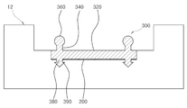
이상에서 설명한 가이드레일(300)을 문틀(12)에 설치한 모습이 도 2 본 발명의 일실시례에 따른 미닫이 도어의 정면도에 도시되어 있다.Figure 2 is a front view of the sliding door according to one embodiment of the present invention in which the
도 2에 도시된 바와 같이 상기 베이스판(320)의 하부면과 안착부 사이에는 접착제(200)를 통하여 고정 부착됨을 알 수 있다.As shown in FIG. 2, the lower surface of the
또한, 사용기간의 장기화됨에 따라 상기 접착제(200)의 접착력이 감퇴하더라도 체결돌기(390)와 함몰홈이 서로 맞물려 있음으로써 고정된다.Further, as the use period is prolonged, even if the adhesive force of the
여기서 삽입돌기(380) 및 체결돌기(390)를 함몰홈에 삽입하는 방법은 문틀(12) 조립 전 측면으로 삽입하는 방법이 있고, 기존에 사용하던 문틀(12)에서는 억지끼움을 통해 설치할 수 있다.Here, the method of inserting the
덧붙여, 기존에 사용하던 문틀에 설치하는 경우는 상기와 같이 체결돌기(390)를 날개 및 판형으로 제작하는 것이 함몰홈에 체결돌기(390)를 삽입하기에 좀더 용이하다. In addition, in the case of installing on the door frame used in the past, it is easier to insert the
다음으로, 도 3 본 발명의 일실시례에 따른 미닫이 도어의 사용상태를 나타낸 사시도를 참고하여 본 발명에 따른 미닫이 도어(10)의 사용 양태를 살펴보도록 한다.Next, the use of the sliding
먼저, 하측 문틀(12)에 안착부가 함몰형성되고, 안착부에는 함몰홈이 형성된다.First, the seat portion is recessed in the
그리고 상기 안착부에 접착제(200)를 바르고, 상기 가이드레일(300)을 상기 베이스판(320)과 상기 삽입돌기(380) 및 체결돌기(390)에 맞추어 삽입된다.The adhesive 200 is applied to the seating part and the
그리고 본 발명에 따른 미닫이 도어(10)를 설치하고자 하는 부위에 하측 문틀을 포함하여 문틀(12)을 완성, 설치한다.Then, the
다음, 도어(14)의 저면에는 중앙에 홈이 형성되어 있는 하나 이상의 롤러(16)를 부착하고, 이송 가능하도록 완성된 상기 도어(14)를 상기 문틀(12)에 설치하는데, 상기 도어(14)의 하측 문틀에 삽입된 가이드레일(300)의 안내돌기(360)와 상기 도어(14)의 저면에 부착된 롤러(16)의 홈이 맞도록 설치하여 안내돌기(360)를 따라 도어(14)가 슬라이딩 되도록 본 발명에 따른 미닫이 도어(10)를 완성한다.Next, one or
여기서, 통상의 미닫이 도어(10)는 겹칠 수 있는 도어(14)가 2개인 경우가 대부분이므로 이에 따라 지지레일(340) 및 안내돌기(360)도 2개로 설계하였지만, 겹쳐질 수 있도록 하는 도어(14)의 갯수에 따라 얼마든지 변경하여 제작될 수 있을 것이다.Since the general sliding
끝으로, 이상에서 기술한 실시 예들은 모든 면에서 예시적인 것이며 한정적인 것이 아닌 것으로서 이해되어야 하고, 본 발명의 범위는 상기 상세한 설명보다는 후술하는 특허청구범위에 의하여 나타나며, 특허청구범위의 의미 및 범위 그리고 그 등가 개념으로부터 도출되는 모든 변경 또는 변형된 형태가 본 발명의 범위에 포함되는 것으로 해석되어야 한다.It is to be understood that both the foregoing general description and the following detailed description are exemplary and explanatory and are intended to provide further explanation of the invention as claimed. And all changes or modifications derived from equivalents thereof should be construed as being included within the scope of the present invention.
10: 미닫이 도어
12: 문틀
14: 도어
16: 롤러
100: 안착부
120: 함몰홈
200: 접착제
300: 가이드레일
320: 베이스 판
340: 지지레일
360: 안내돌기
380: 삽입돌기
390: 체결돌기10: Sliding door
12: Door frame
14: Door
16: Roller
100:
120: recessed groove
200: Adhesive
300: Guide rail
320: base plate
340: support rail
360: guide projection
380: insertion projection
390: fastening projection
Claims (4)
상기 가이드 레일은,
상기 문틀의 하부에 함몰형성되는 안착부에 부착되는 베이스 판과, 상기 베이스 판 상부면에 일정한 간격으로 돌출형성되는 하나 이상의 지지 레일과, 상기 베이스 판 하부면에 돌출형성되어 상기 안착부에 형성된 함몰홈에 결합되는 하나 이상의 삽입 돌기를 포함하되,
상기 베이스 판은 상기 안착부에 접착제를 통해서 결합되는 것을 특징으로 하는 미닫이 도어.A sliding door including a door, a door frame on which the door is installed, and a guide rail installed on a lower portion of the door frame to guide movement of the sliding member of the door,
The guide rails
At least one support rail protruding from the upper surface of the base plate at a predetermined interval; a protrusion formed on the lower surface of the base plate, And at least one insertion protrusion coupled to the groove,
Wherein the base plate is coupled to the seating portion through an adhesive.
상기 삽입 돌기는,
단부에 체결 돌기가 형성된 것을 특징으로 하는 미닫이 도어.The method according to claim 1,
The insertion protrusion
And a fastening protrusion is formed at an end thereof.
상기 안착부의 깊이는,
상기 베이스 판의 두께에 대응되는 것을 특징으로 하는 미닫이 도어.
The method according to claim 1,
The depth of the seat portion
And the thickness of the base plate corresponds to the thickness of the base plate.
상기 삽입돌기는,
상기 지지레일이 형성되는 지점에 대응형성되는 것을 특징으로 하는 미닫이 도어.The method according to claim 1,
The insertion protrusion
Wherein the sliding door is formed at a position where the support rail is formed.
Priority Applications (1)
| Application Number | Priority Date | Filing Date | Title |
|---|---|---|---|
| KR1020160054617A KR20170124785A (en) | 2016-05-03 | 2016-05-03 | a slide door |
Applications Claiming Priority (1)
| Application Number | Priority Date | Filing Date | Title |
|---|---|---|---|
| KR1020160054617A KR20170124785A (en) | 2016-05-03 | 2016-05-03 | a slide door |
Publications (1)
| Publication Number | Publication Date |
|---|---|
| KR20170124785A true KR20170124785A (en) | 2017-11-13 |
Family
ID=60386032
Family Applications (1)
| Application Number | Title | Priority Date | Filing Date |
|---|---|---|---|
| KR1020160054617A KR20170124785A (en) | 2016-05-03 | 2016-05-03 | a slide door |
Country Status (1)
| Country | Link |
|---|---|
| KR (1) | KR20170124785A (en) |
Cited By (2)
| Publication number | Priority date | Publication date | Assignee | Title |
|---|---|---|---|---|
| CN108952403A (en) * | 2018-08-25 | 2018-12-07 | 广东炬森五金精密制造有限公司 | A kind of flat sliding door lower guide plate mounting structure of internal-suction type |
| KR102079502B1 (en) * | 2019-08-28 | 2020-02-20 | 김병철 | Slide door for classroom |
-
2016
- 2016-05-03 KR KR1020160054617A patent/KR20170124785A/en not_active Application Discontinuation
Cited By (2)
| Publication number | Priority date | Publication date | Assignee | Title |
|---|---|---|---|---|
| CN108952403A (en) * | 2018-08-25 | 2018-12-07 | 广东炬森五金精密制造有限公司 | A kind of flat sliding door lower guide plate mounting structure of internal-suction type |
| KR102079502B1 (en) * | 2019-08-28 | 2020-02-20 | 김병철 | Slide door for classroom |
Similar Documents
| Publication | Publication Date | Title |
|---|---|---|
| US10376053B2 (en) | Drawer | |
| US20090045705A1 (en) | Door for a household appliance | |
| CZ26432U1 (en) | Assembly of shower bath door | |
| US8973315B2 (en) | Window trim system | |
| US10689850B2 (en) | System for mounting a plurality of panels | |
| KR20170119212A (en) | roller bracket for sliding door | |
| KR20170124785A (en) | a slide door | |
| EP2004923A1 (en) | A panel attachment clip | |
| KR101864016B1 (en) | Door roller | |
| KR101314873B1 (en) | Finishing member, ceiling of the building | |
| CA2821586A1 (en) | Hardware mounting bracket, assembly and hardware | |
| US3338008A (en) | Wooden knock-down door buck construction | |
| US20180125268A1 (en) | Planar display assembly | |
| JP5085884B2 (en) | Cover frame and joinery | |
| US20150033635A1 (en) | Door Assembly | |
| RU169452U1 (en) | CONSTRUCTION DEVICE OF THE ELEMENT PROVIDING INSTALLATION AND FIXING OF PROFILED HANDLE | |
| US3654731A (en) | Metal door frames | |
| CA2970001C (en) | Frame for a movable furniture part | |
| JP3206776U (en) | Tile mounting bracket | |
| KR20180095761A (en) | Clip bracket and ceiling finishing apparatus | |
| KR200360249Y1 (en) | Fixing hanger for ceiling pannel | |
| AU2015202234A1 (en) | A Panel System and Components therefor | |
| CN105640095A (en) | A covering device for a flat side of a wall element | |
| JP5427098B2 (en) | Rail device | |
| KR101671843B1 (en) | Side contact type skin plate for building |
Legal Events
| Date | Code | Title | Description |
|---|---|---|---|
| A201 | Request for examination | ||
| E902 | Notification of reason for refusal | ||
| E601 | Decision to refuse application |