KR20170122733A - Multilayer medical devices and methods - Google Patents
Multilayer medical devices and methods Download PDFInfo
- Publication number
- KR20170122733A KR20170122733A KR1020177022513A KR20177022513A KR20170122733A KR 20170122733 A KR20170122733 A KR 20170122733A KR 1020177022513 A KR1020177022513 A KR 1020177022513A KR 20177022513 A KR20177022513 A KR 20177022513A KR 20170122733 A KR20170122733 A KR 20170122733A
- Authority
- KR
- South Korea
- Prior art keywords
- layer
- eptfe
- sublayer
- prosthesis
- vascular prosthesis
- Prior art date
Links
- 238000000034 method Methods 0.000 title claims description 47
- 230000002792 vascular Effects 0.000 claims abstract description 45
- 239000000835 fiber Substances 0.000 claims description 103
- 239000011148 porous material Substances 0.000 claims description 63
- 229920001343 polytetrafluoroethylene Polymers 0.000 claims description 35
- 239000004810 polytetrafluoroethylene Substances 0.000 claims description 35
- 239000004812 Fluorinated ethylene propylene Substances 0.000 claims description 31
- 229920009441 perflouroethylene propylene Polymers 0.000 claims description 31
- 239000006260 foam Substances 0.000 claims description 30
- 210000004027 cell Anatomy 0.000 claims description 21
- 238000009987 spinning Methods 0.000 claims description 21
- 239000012530 fluid Substances 0.000 claims description 17
- 210000003743 erythrocyte Anatomy 0.000 claims description 15
- HQQADJVZYDDRJT-UHFFFAOYSA-N ethene;prop-1-ene Chemical group C=C.CC=C HQQADJVZYDDRJT-UHFFFAOYSA-N 0.000 claims description 9
- -1 polytetrafluoroethylene Polymers 0.000 claims description 9
- 238000004519 manufacturing process Methods 0.000 claims description 6
- 238000005245 sintering Methods 0.000 claims description 6
- 238000005187 foaming Methods 0.000 claims description 4
- 230000009087 cell motility Effects 0.000 claims 3
- 239000010410 layer Substances 0.000 description 224
- 239000000463 material Substances 0.000 description 74
- 210000001519 tissue Anatomy 0.000 description 18
- 239000012528 membrane Substances 0.000 description 15
- 238000001523 electrospinning Methods 0.000 description 14
- 229920000642 polymer Polymers 0.000 description 14
- 230000008569 process Effects 0.000 description 14
- 238000001878 scanning electron micrograph Methods 0.000 description 10
- 230000006835 compression Effects 0.000 description 9
- 238000007906 compression Methods 0.000 description 9
- 210000002889 endothelial cell Anatomy 0.000 description 9
- XLYOFNOQVPJJNP-UHFFFAOYSA-N water Substances O XLYOFNOQVPJJNP-UHFFFAOYSA-N 0.000 description 9
- 210000004369 blood Anatomy 0.000 description 8
- 239000008280 blood Substances 0.000 description 8
- 239000006185 dispersion Substances 0.000 description 8
- 229910052751 metal Inorganic materials 0.000 description 8
- 239000002184 metal Substances 0.000 description 8
- 229920003171 Poly (ethylene oxide) Polymers 0.000 description 7
- 230000035699 permeability Effects 0.000 description 7
- 239000002356 single layer Substances 0.000 description 7
- 239000000758 substrate Substances 0.000 description 7
- 230000015572 biosynthetic process Effects 0.000 description 6
- 230000010261 cell growth Effects 0.000 description 6
- 238000000576 coating method Methods 0.000 description 6
- 230000012292 cell migration Effects 0.000 description 5
- 239000011248 coating agent Substances 0.000 description 5
- 230000003511 endothelial effect Effects 0.000 description 5
- 210000003038 endothelium Anatomy 0.000 description 5
- 238000010438 heat treatment Methods 0.000 description 5
- 239000002904 solvent Substances 0.000 description 5
- 238000012360 testing method Methods 0.000 description 5
- 230000008467 tissue growth Effects 0.000 description 5
- 102000008186 Collagen Human genes 0.000 description 4
- 108010035532 Collagen Proteins 0.000 description 4
- 239000012620 biological material Substances 0.000 description 4
- 229920001436 collagen Polymers 0.000 description 4
- 239000002131 composite material Substances 0.000 description 4
- 230000012010 growth Effects 0.000 description 4
- 230000028709 inflammatory response Effects 0.000 description 4
- 238000005259 measurement Methods 0.000 description 4
- 230000005012 migration Effects 0.000 description 4
- 238000013508 migration Methods 0.000 description 4
- 230000005855 radiation Effects 0.000 description 4
- 230000017531 blood circulation Effects 0.000 description 3
- 230000001413 cellular effect Effects 0.000 description 3
- 239000003795 chemical substances by application Substances 0.000 description 3
- 230000006870 function Effects 0.000 description 3
- 208000014674 injury Diseases 0.000 description 3
- 230000003993 interaction Effects 0.000 description 3
- 230000033001 locomotion Effects 0.000 description 3
- 230000002829 reductive effect Effects 0.000 description 3
- 230000001225 therapeutic effect Effects 0.000 description 3
- 230000008733 trauma Effects 0.000 description 3
- 206010019909 Hernia Diseases 0.000 description 2
- 208000007536 Thrombosis Diseases 0.000 description 2
- 238000004458 analytical method Methods 0.000 description 2
- 230000004888 barrier function Effects 0.000 description 2
- 239000003124 biologic agent Substances 0.000 description 2
- 230000000903 blocking effect Effects 0.000 description 2
- 230000023555 blood coagulation Effects 0.000 description 2
- 238000004364 calculation method Methods 0.000 description 2
- 239000000919 ceramic Substances 0.000 description 2
- 238000006243 chemical reaction Methods 0.000 description 2
- 238000004891 communication Methods 0.000 description 2
- 238000013461 design Methods 0.000 description 2
- 230000009969 flowable effect Effects 0.000 description 2
- 230000035876 healing Effects 0.000 description 2
- 239000007788 liquid Substances 0.000 description 2
- 238000011068 loading method Methods 0.000 description 2
- 229910001000 nickel titanium Inorganic materials 0.000 description 2
- HLXZNVUGXRDIFK-UHFFFAOYSA-N nickel titanium Chemical compound [Ti].[Ti].[Ti].[Ti].[Ti].[Ti].[Ti].[Ti].[Ti].[Ti].[Ti].[Ni].[Ni].[Ni].[Ni].[Ni].[Ni].[Ni].[Ni].[Ni].[Ni].[Ni].[Ni].[Ni].[Ni] HLXZNVUGXRDIFK-UHFFFAOYSA-N 0.000 description 2
- 230000035515 penetration Effects 0.000 description 2
- 229920005594 polymer fiber Polymers 0.000 description 2
- 238000013515 script Methods 0.000 description 2
- 239000010935 stainless steel Substances 0.000 description 2
- 229910001220 stainless steel Inorganic materials 0.000 description 2
- 230000005944 tissue migration Effects 0.000 description 2
- 210000005166 vasculature Anatomy 0.000 description 2
- 206010002329 Aneurysm Diseases 0.000 description 1
- 201000001320 Atherosclerosis Diseases 0.000 description 1
- 238000012935 Averaging Methods 0.000 description 1
- 206010061218 Inflammation Diseases 0.000 description 1
- 229920001410 Microfiber Polymers 0.000 description 1
- 208000031481 Pathologic Constriction Diseases 0.000 description 1
- 206010053648 Vascular occlusion Diseases 0.000 description 1
- 206010047139 Vasoconstriction Diseases 0.000 description 1
- 208000027418 Wounds and injury Diseases 0.000 description 1
- 208000002223 abdominal aortic aneurysm Diseases 0.000 description 1
- 230000003187 abdominal effect Effects 0.000 description 1
- 230000002411 adverse Effects 0.000 description 1
- 229910045601 alloy Inorganic materials 0.000 description 1
- 239000000956 alloy Substances 0.000 description 1
- WYTGDNHDOZPMIW-RCBQFDQVSA-N alstonine Natural products C1=CC2=C3C=CC=CC3=NC2=C2N1C[C@H]1[C@H](C)OC=C(C(=O)OC)[C@H]1C2 WYTGDNHDOZPMIW-RCBQFDQVSA-N 0.000 description 1
- 230000033115 angiogenesis Effects 0.000 description 1
- 208000007474 aortic aneurysm Diseases 0.000 description 1
- 239000011324 bead Substances 0.000 description 1
- 230000008901 benefit Effects 0.000 description 1
- 210000000013 bile duct Anatomy 0.000 description 1
- 230000000975 bioactive effect Effects 0.000 description 1
- 230000008512 biological response Effects 0.000 description 1
- 210000004204 blood vessel Anatomy 0.000 description 1
- 239000002775 capsule Substances 0.000 description 1
- 230000008859 change Effects 0.000 description 1
- 238000010276 construction Methods 0.000 description 1
- 238000001816 cooling Methods 0.000 description 1
- 238000000151 deposition Methods 0.000 description 1
- 230000006866 deterioration Effects 0.000 description 1
- 238000010586 diagram Methods 0.000 description 1
- 238000007598 dipping method Methods 0.000 description 1
- 239000004815 dispersion polymer Substances 0.000 description 1
- 239000003814 drug Substances 0.000 description 1
- 229940079593 drug Drugs 0.000 description 1
- 230000002526 effect on cardiovascular system Effects 0.000 description 1
- 230000000694 effects Effects 0.000 description 1
- 230000005684 electric field Effects 0.000 description 1
- 230000008030 elimination Effects 0.000 description 1
- 238000003379 elimination reaction Methods 0.000 description 1
- 230000002357 endometrial effect Effects 0.000 description 1
- 230000000913 erythropoietic effect Effects 0.000 description 1
- 210000003238 esophagus Anatomy 0.000 description 1
- 238000005530 etching Methods 0.000 description 1
- 238000001125 extrusion Methods 0.000 description 1
- 239000002657 fibrous material Substances 0.000 description 1
- 230000002496 gastric effect Effects 0.000 description 1
- 210000003709 heart valve Anatomy 0.000 description 1
- 230000002706 hydrostatic effect Effects 0.000 description 1
- 206010020718 hyperplasia Diseases 0.000 description 1
- 239000007943 implant Substances 0.000 description 1
- 238000002513 implantation Methods 0.000 description 1
- 230000008595 infiltration Effects 0.000 description 1
- 238000001764 infiltration Methods 0.000 description 1
- 230000002757 inflammatory effect Effects 0.000 description 1
- 230000004054 inflammatory process Effects 0.000 description 1
- 230000002401 inhibitory effect Effects 0.000 description 1
- 239000002648 laminated material Substances 0.000 description 1
- 238000003698 laser cutting Methods 0.000 description 1
- 210000003041 ligament Anatomy 0.000 description 1
- 230000000670 limiting effect Effects 0.000 description 1
- 230000007774 longterm Effects 0.000 description 1
- 210000002540 macrophage Anatomy 0.000 description 1
- 238000000691 measurement method Methods 0.000 description 1
- 230000007246 mechanism Effects 0.000 description 1
- 150000002739 metals Chemical class 0.000 description 1
- 239000003658 microfiber Substances 0.000 description 1
- 239000000203 mixture Substances 0.000 description 1
- 239000002121 nanofiber Substances 0.000 description 1
- 239000002086 nanomaterial Substances 0.000 description 1
- 210000000056 organ Anatomy 0.000 description 1
- 239000002245 particle Substances 0.000 description 1
- 230000002093 peripheral effect Effects 0.000 description 1
- 238000012805 post-processing Methods 0.000 description 1
- 238000004663 powder metallurgy Methods 0.000 description 1
- 238000003825 pressing Methods 0.000 description 1
- 238000012545 processing Methods 0.000 description 1
- 230000035755 proliferation Effects 0.000 description 1
- 230000001737 promoting effect Effects 0.000 description 1
- 230000002685 pulmonary effect Effects 0.000 description 1
- 238000003908 quality control method Methods 0.000 description 1
- 208000037803 restenosis Diseases 0.000 description 1
- 238000000926 separation method Methods 0.000 description 1
- 229910001285 shape-memory alloy Inorganic materials 0.000 description 1
- 238000005507 spraying Methods 0.000 description 1
- 238000007655 standard test method Methods 0.000 description 1
- 230000036262 stenosis Effects 0.000 description 1
- 208000037804 stenosis Diseases 0.000 description 1
- 239000000126 substance Substances 0.000 description 1
- 210000000115 thoracic cavity Anatomy 0.000 description 1
- 230000025033 vasoconstriction Effects 0.000 description 1
- 230000024883 vasodilation Effects 0.000 description 1
- 230000035899 viability Effects 0.000 description 1
- 239000002699 waste material Substances 0.000 description 1
Images


Classifications
-
- A—HUMAN NECESSITIES
- A61—MEDICAL OR VETERINARY SCIENCE; HYGIENE
- A61F—FILTERS IMPLANTABLE INTO BLOOD VESSELS; PROSTHESES; DEVICES PROVIDING PATENCY TO, OR PREVENTING COLLAPSING OF, TUBULAR STRUCTURES OF THE BODY, e.g. STENTS; ORTHOPAEDIC, NURSING OR CONTRACEPTIVE DEVICES; FOMENTATION; TREATMENT OR PROTECTION OF EYES OR EARS; BANDAGES, DRESSINGS OR ABSORBENT PADS; FIRST-AID KITS
- A61F2/00—Filters implantable into blood vessels; Prostheses, i.e. artificial substitutes or replacements for parts of the body; Appliances for connecting them with the body; Devices providing patency to, or preventing collapsing of, tubular structures of the body, e.g. stents
- A61F2/02—Prostheses implantable into the body
- A61F2/04—Hollow or tubular parts of organs, e.g. bladders, tracheae, bronchi or bile ducts
- A61F2/06—Blood vessels
- A61F2/07—Stent-grafts
-
- A—HUMAN NECESSITIES
- A61—MEDICAL OR VETERINARY SCIENCE; HYGIENE
- A61F—FILTERS IMPLANTABLE INTO BLOOD VESSELS; PROSTHESES; DEVICES PROVIDING PATENCY TO, OR PREVENTING COLLAPSING OF, TUBULAR STRUCTURES OF THE BODY, e.g. STENTS; ORTHOPAEDIC, NURSING OR CONTRACEPTIVE DEVICES; FOMENTATION; TREATMENT OR PROTECTION OF EYES OR EARS; BANDAGES, DRESSINGS OR ABSORBENT PADS; FIRST-AID KITS
- A61F2/00—Filters implantable into blood vessels; Prostheses, i.e. artificial substitutes or replacements for parts of the body; Appliances for connecting them with the body; Devices providing patency to, or preventing collapsing of, tubular structures of the body, e.g. stents
- A61F2/82—Devices providing patency to, or preventing collapsing of, tubular structures of the body, e.g. stents
- A61F2/86—Stents in a form characterised by the wire-like elements; Stents in the form characterised by a net-like or mesh-like structure
- A61F2/90—Stents in a form characterised by the wire-like elements; Stents in the form characterised by a net-like or mesh-like structure characterised by a net-like or mesh-like structure
- A61F2/91—Stents in a form characterised by the wire-like elements; Stents in the form characterised by a net-like or mesh-like structure characterised by a net-like or mesh-like structure made from perforated sheet material or tubes, e.g. perforated by laser cuts or etched holes
- A61F2/915—Stents in a form characterised by the wire-like elements; Stents in the form characterised by a net-like or mesh-like structure characterised by a net-like or mesh-like structure made from perforated sheet material or tubes, e.g. perforated by laser cuts or etched holes with bands having a meander structure, adjacent bands being connected to each other
-
- A—HUMAN NECESSITIES
- A61—MEDICAL OR VETERINARY SCIENCE; HYGIENE
- A61F—FILTERS IMPLANTABLE INTO BLOOD VESSELS; PROSTHESES; DEVICES PROVIDING PATENCY TO, OR PREVENTING COLLAPSING OF, TUBULAR STRUCTURES OF THE BODY, e.g. STENTS; ORTHOPAEDIC, NURSING OR CONTRACEPTIVE DEVICES; FOMENTATION; TREATMENT OR PROTECTION OF EYES OR EARS; BANDAGES, DRESSINGS OR ABSORBENT PADS; FIRST-AID KITS
- A61F2/00—Filters implantable into blood vessels; Prostheses, i.e. artificial substitutes or replacements for parts of the body; Appliances for connecting them with the body; Devices providing patency to, or preventing collapsing of, tubular structures of the body, e.g. stents
- A61F2/82—Devices providing patency to, or preventing collapsing of, tubular structures of the body, e.g. stents
- A61F2/94—Stents retaining their form, i.e. not being deformable, after placement in the predetermined place
- A61F2/945—Stents retaining their form, i.e. not being deformable, after placement in the predetermined place hardenable, e.g. stents formed in situ
-
- A—HUMAN NECESSITIES
- A61—MEDICAL OR VETERINARY SCIENCE; HYGIENE
- A61L—METHODS OR APPARATUS FOR STERILISING MATERIALS OR OBJECTS IN GENERAL; DISINFECTION, STERILISATION OR DEODORISATION OF AIR; CHEMICAL ASPECTS OF BANDAGES, DRESSINGS, ABSORBENT PADS OR SURGICAL ARTICLES; MATERIALS FOR BANDAGES, DRESSINGS, ABSORBENT PADS OR SURGICAL ARTICLES
- A61L27/00—Materials for grafts or prostheses or for coating grafts or prostheses
- A61L27/14—Macromolecular materials
- A61L27/18—Macromolecular materials obtained otherwise than by reactions only involving carbon-to-carbon unsaturated bonds
-
- A—HUMAN NECESSITIES
- A61—MEDICAL OR VETERINARY SCIENCE; HYGIENE
- A61L—METHODS OR APPARATUS FOR STERILISING MATERIALS OR OBJECTS IN GENERAL; DISINFECTION, STERILISATION OR DEODORISATION OF AIR; CHEMICAL ASPECTS OF BANDAGES, DRESSINGS, ABSORBENT PADS OR SURGICAL ARTICLES; MATERIALS FOR BANDAGES, DRESSINGS, ABSORBENT PADS OR SURGICAL ARTICLES
- A61L27/00—Materials for grafts or prostheses or for coating grafts or prostheses
- A61L27/50—Materials characterised by their function or physical properties, e.g. injectable or lubricating compositions, shape-memory materials, surface modified materials
- A61L27/507—Materials characterised by their function or physical properties, e.g. injectable or lubricating compositions, shape-memory materials, surface modified materials for artificial blood vessels
-
- A—HUMAN NECESSITIES
- A61—MEDICAL OR VETERINARY SCIENCE; HYGIENE
- A61L—METHODS OR APPARATUS FOR STERILISING MATERIALS OR OBJECTS IN GENERAL; DISINFECTION, STERILISATION OR DEODORISATION OF AIR; CHEMICAL ASPECTS OF BANDAGES, DRESSINGS, ABSORBENT PADS OR SURGICAL ARTICLES; MATERIALS FOR BANDAGES, DRESSINGS, ABSORBENT PADS OR SURGICAL ARTICLES
- A61L31/00—Materials for other surgical articles, e.g. stents, stent-grafts, shunts, surgical drapes, guide wires, materials for adhesion prevention, occluding devices, surgical gloves, tissue fixation devices
- A61L31/04—Macromolecular materials
- A61L31/06—Macromolecular materials obtained otherwise than by reactions only involving carbon-to-carbon unsaturated bonds
-
- A—HUMAN NECESSITIES
- A61—MEDICAL OR VETERINARY SCIENCE; HYGIENE
- A61L—METHODS OR APPARATUS FOR STERILISING MATERIALS OR OBJECTS IN GENERAL; DISINFECTION, STERILISATION OR DEODORISATION OF AIR; CHEMICAL ASPECTS OF BANDAGES, DRESSINGS, ABSORBENT PADS OR SURGICAL ARTICLES; MATERIALS FOR BANDAGES, DRESSINGS, ABSORBENT PADS OR SURGICAL ARTICLES
- A61L31/00—Materials for other surgical articles, e.g. stents, stent-grafts, shunts, surgical drapes, guide wires, materials for adhesion prevention, occluding devices, surgical gloves, tissue fixation devices
- A61L31/14—Materials characterised by their function or physical properties, e.g. injectable or lubricating compositions, shape-memory materials, surface modified materials
- A61L31/146—Porous materials, e.g. foams or sponges
-
- B—PERFORMING OPERATIONS; TRANSPORTING
- B32—LAYERED PRODUCTS
- B32B—LAYERED PRODUCTS, i.e. PRODUCTS BUILT-UP OF STRATA OF FLAT OR NON-FLAT, e.g. CELLULAR OR HONEYCOMB, FORM
- B32B27/00—Layered products comprising a layer of synthetic resin
- B32B27/06—Layered products comprising a layer of synthetic resin as the main or only constituent of a layer, which is next to another layer of the same or of a different material
- B32B27/08—Layered products comprising a layer of synthetic resin as the main or only constituent of a layer, which is next to another layer of the same or of a different material of synthetic resin
-
- B—PERFORMING OPERATIONS; TRANSPORTING
- B32—LAYERED PRODUCTS
- B32B—LAYERED PRODUCTS, i.e. PRODUCTS BUILT-UP OF STRATA OF FLAT OR NON-FLAT, e.g. CELLULAR OR HONEYCOMB, FORM
- B32B27/00—Layered products comprising a layer of synthetic resin
- B32B27/32—Layered products comprising a layer of synthetic resin comprising polyolefins
- B32B27/322—Layered products comprising a layer of synthetic resin comprising polyolefins comprising halogenated polyolefins, e.g. PTFE
-
- C—CHEMISTRY; METALLURGY
- C08—ORGANIC MACROMOLECULAR COMPOUNDS; THEIR PREPARATION OR CHEMICAL WORKING-UP; COMPOSITIONS BASED THEREON
- C08L—COMPOSITIONS OF MACROMOLECULAR COMPOUNDS
- C08L27/00—Compositions of homopolymers or copolymers of compounds having one or more unsaturated aliphatic radicals, each having only one carbon-to-carbon double bond, and at least one being terminated by a halogen; Compositions of derivatives of such polymers
- C08L27/02—Compositions of homopolymers or copolymers of compounds having one or more unsaturated aliphatic radicals, each having only one carbon-to-carbon double bond, and at least one being terminated by a halogen; Compositions of derivatives of such polymers not modified by chemical after-treatment
- C08L27/12—Compositions of homopolymers or copolymers of compounds having one or more unsaturated aliphatic radicals, each having only one carbon-to-carbon double bond, and at least one being terminated by a halogen; Compositions of derivatives of such polymers not modified by chemical after-treatment containing fluorine atoms
- C08L27/18—Homopolymers or copolymers or tetrafluoroethene
-
- A—HUMAN NECESSITIES
- A61—MEDICAL OR VETERINARY SCIENCE; HYGIENE
- A61F—FILTERS IMPLANTABLE INTO BLOOD VESSELS; PROSTHESES; DEVICES PROVIDING PATENCY TO, OR PREVENTING COLLAPSING OF, TUBULAR STRUCTURES OF THE BODY, e.g. STENTS; ORTHOPAEDIC, NURSING OR CONTRACEPTIVE DEVICES; FOMENTATION; TREATMENT OR PROTECTION OF EYES OR EARS; BANDAGES, DRESSINGS OR ABSORBENT PADS; FIRST-AID KITS
- A61F2/00—Filters implantable into blood vessels; Prostheses, i.e. artificial substitutes or replacements for parts of the body; Appliances for connecting them with the body; Devices providing patency to, or preventing collapsing of, tubular structures of the body, e.g. stents
- A61F2/02—Prostheses implantable into the body
- A61F2/04—Hollow or tubular parts of organs, e.g. bladders, tracheae, bronchi or bile ducts
- A61F2/06—Blood vessels
- A61F2/07—Stent-grafts
- A61F2002/072—Encapsulated stents, e.g. wire or whole stent embedded in lining
-
- A—HUMAN NECESSITIES
- A61—MEDICAL OR VETERINARY SCIENCE; HYGIENE
- A61F—FILTERS IMPLANTABLE INTO BLOOD VESSELS; PROSTHESES; DEVICES PROVIDING PATENCY TO, OR PREVENTING COLLAPSING OF, TUBULAR STRUCTURES OF THE BODY, e.g. STENTS; ORTHOPAEDIC, NURSING OR CONTRACEPTIVE DEVICES; FOMENTATION; TREATMENT OR PROTECTION OF EYES OR EARS; BANDAGES, DRESSINGS OR ABSORBENT PADS; FIRST-AID KITS
- A61F2210/00—Particular material properties of prostheses classified in groups A61F2/00 - A61F2/26 or A61F2/82 or A61F9/00 or A61F11/00 or subgroups thereof
- A61F2210/0014—Particular material properties of prostheses classified in groups A61F2/00 - A61F2/26 or A61F2/82 or A61F9/00 or A61F11/00 or subgroups thereof using shape memory or superelastic materials, e.g. nitinol
-
- A—HUMAN NECESSITIES
- A61—MEDICAL OR VETERINARY SCIENCE; HYGIENE
- A61F—FILTERS IMPLANTABLE INTO BLOOD VESSELS; PROSTHESES; DEVICES PROVIDING PATENCY TO, OR PREVENTING COLLAPSING OF, TUBULAR STRUCTURES OF THE BODY, e.g. STENTS; ORTHOPAEDIC, NURSING OR CONTRACEPTIVE DEVICES; FOMENTATION; TREATMENT OR PROTECTION OF EYES OR EARS; BANDAGES, DRESSINGS OR ABSORBENT PADS; FIRST-AID KITS
- A61F2210/00—Particular material properties of prostheses classified in groups A61F2/00 - A61F2/26 or A61F2/82 or A61F9/00 or A61F11/00 or subgroups thereof
- A61F2210/0076—Particular material properties of prostheses classified in groups A61F2/00 - A61F2/26 or A61F2/82 or A61F9/00 or A61F11/00 or subgroups thereof multilayered, e.g. laminated structures
-
- A—HUMAN NECESSITIES
- A61—MEDICAL OR VETERINARY SCIENCE; HYGIENE
- A61F—FILTERS IMPLANTABLE INTO BLOOD VESSELS; PROSTHESES; DEVICES PROVIDING PATENCY TO, OR PREVENTING COLLAPSING OF, TUBULAR STRUCTURES OF THE BODY, e.g. STENTS; ORTHOPAEDIC, NURSING OR CONTRACEPTIVE DEVICES; FOMENTATION; TREATMENT OR PROTECTION OF EYES OR EARS; BANDAGES, DRESSINGS OR ABSORBENT PADS; FIRST-AID KITS
- A61F2220/00—Fixations or connections for prostheses classified in groups A61F2/00 - A61F2/26 or A61F2/82 or A61F9/00 or A61F11/00 or subgroups thereof
- A61F2220/0025—Connections or couplings between prosthetic parts, e.g. between modular parts; Connecting elements
- A61F2220/005—Connections or couplings between prosthetic parts, e.g. between modular parts; Connecting elements using adhesives
-
- A—HUMAN NECESSITIES
- A61—MEDICAL OR VETERINARY SCIENCE; HYGIENE
- A61F—FILTERS IMPLANTABLE INTO BLOOD VESSELS; PROSTHESES; DEVICES PROVIDING PATENCY TO, OR PREVENTING COLLAPSING OF, TUBULAR STRUCTURES OF THE BODY, e.g. STENTS; ORTHOPAEDIC, NURSING OR CONTRACEPTIVE DEVICES; FOMENTATION; TREATMENT OR PROTECTION OF EYES OR EARS; BANDAGES, DRESSINGS OR ABSORBENT PADS; FIRST-AID KITS
- A61F2240/00—Manufacturing or designing of prostheses classified in groups A61F2/00 - A61F2/26 or A61F2/82 or A61F9/00 or A61F11/00 or subgroups thereof
- A61F2240/001—Designing or manufacturing processes
- A61F2240/002—Designing or making customized prostheses
-
- A—HUMAN NECESSITIES
- A61—MEDICAL OR VETERINARY SCIENCE; HYGIENE
- A61F—FILTERS IMPLANTABLE INTO BLOOD VESSELS; PROSTHESES; DEVICES PROVIDING PATENCY TO, OR PREVENTING COLLAPSING OF, TUBULAR STRUCTURES OF THE BODY, e.g. STENTS; ORTHOPAEDIC, NURSING OR CONTRACEPTIVE DEVICES; FOMENTATION; TREATMENT OR PROTECTION OF EYES OR EARS; BANDAGES, DRESSINGS OR ABSORBENT PADS; FIRST-AID KITS
- A61F2250/00—Special features of prostheses classified in groups A61F2/00 - A61F2/26 or A61F2/82 or A61F9/00 or A61F11/00 or subgroups thereof
- A61F2250/0014—Special features of prostheses classified in groups A61F2/00 - A61F2/26 or A61F2/82 or A61F9/00 or A61F11/00 or subgroups thereof having different values of a given property or geometrical feature, e.g. mechanical property or material property, at different locations within the same prosthesis
- A61F2250/0018—Special features of prostheses classified in groups A61F2/00 - A61F2/26 or A61F2/82 or A61F9/00 or A61F11/00 or subgroups thereof having different values of a given property or geometrical feature, e.g. mechanical property or material property, at different locations within the same prosthesis differing in elasticity, stiffness or compressibility
-
- A—HUMAN NECESSITIES
- A61—MEDICAL OR VETERINARY SCIENCE; HYGIENE
- A61F—FILTERS IMPLANTABLE INTO BLOOD VESSELS; PROSTHESES; DEVICES PROVIDING PATENCY TO, OR PREVENTING COLLAPSING OF, TUBULAR STRUCTURES OF THE BODY, e.g. STENTS; ORTHOPAEDIC, NURSING OR CONTRACEPTIVE DEVICES; FOMENTATION; TREATMENT OR PROTECTION OF EYES OR EARS; BANDAGES, DRESSINGS OR ABSORBENT PADS; FIRST-AID KITS
- A61F2250/00—Special features of prostheses classified in groups A61F2/00 - A61F2/26 or A61F2/82 or A61F9/00 or A61F11/00 or subgroups thereof
- A61F2250/0014—Special features of prostheses classified in groups A61F2/00 - A61F2/26 or A61F2/82 or A61F9/00 or A61F11/00 or subgroups thereof having different values of a given property or geometrical feature, e.g. mechanical property or material property, at different locations within the same prosthesis
- A61F2250/0023—Special features of prostheses classified in groups A61F2/00 - A61F2/26 or A61F2/82 or A61F9/00 or A61F11/00 or subgroups thereof having different values of a given property or geometrical feature, e.g. mechanical property or material property, at different locations within the same prosthesis differing in porosity
-
- A—HUMAN NECESSITIES
- A61—MEDICAL OR VETERINARY SCIENCE; HYGIENE
- A61F—FILTERS IMPLANTABLE INTO BLOOD VESSELS; PROSTHESES; DEVICES PROVIDING PATENCY TO, OR PREVENTING COLLAPSING OF, TUBULAR STRUCTURES OF THE BODY, e.g. STENTS; ORTHOPAEDIC, NURSING OR CONTRACEPTIVE DEVICES; FOMENTATION; TREATMENT OR PROTECTION OF EYES OR EARS; BANDAGES, DRESSINGS OR ABSORBENT PADS; FIRST-AID KITS
- A61F2250/00—Special features of prostheses classified in groups A61F2/00 - A61F2/26 or A61F2/82 or A61F9/00 or A61F11/00 or subgroups thereof
- A61F2250/0014—Special features of prostheses classified in groups A61F2/00 - A61F2/26 or A61F2/82 or A61F9/00 or A61F11/00 or subgroups thereof having different values of a given property or geometrical feature, e.g. mechanical property or material property, at different locations within the same prosthesis
- A61F2250/0028—Special features of prostheses classified in groups A61F2/00 - A61F2/26 or A61F2/82 or A61F9/00 or A61F11/00 or subgroups thereof having different values of a given property or geometrical feature, e.g. mechanical property or material property, at different locations within the same prosthesis differing in fibre orientations
-
- A—HUMAN NECESSITIES
- A61—MEDICAL OR VETERINARY SCIENCE; HYGIENE
- A61F—FILTERS IMPLANTABLE INTO BLOOD VESSELS; PROSTHESES; DEVICES PROVIDING PATENCY TO, OR PREVENTING COLLAPSING OF, TUBULAR STRUCTURES OF THE BODY, e.g. STENTS; ORTHOPAEDIC, NURSING OR CONTRACEPTIVE DEVICES; FOMENTATION; TREATMENT OR PROTECTION OF EYES OR EARS; BANDAGES, DRESSINGS OR ABSORBENT PADS; FIRST-AID KITS
- A61F2250/00—Special features of prostheses classified in groups A61F2/00 - A61F2/26 or A61F2/82 or A61F9/00 or A61F11/00 or subgroups thereof
- A61F2250/0014—Special features of prostheses classified in groups A61F2/00 - A61F2/26 or A61F2/82 or A61F9/00 or A61F11/00 or subgroups thereof having different values of a given property or geometrical feature, e.g. mechanical property or material property, at different locations within the same prosthesis
- A61F2250/0051—Special features of prostheses classified in groups A61F2/00 - A61F2/26 or A61F2/82 or A61F9/00 or A61F11/00 or subgroups thereof having different values of a given property or geometrical feature, e.g. mechanical property or material property, at different locations within the same prosthesis differing in tissue ingrowth capacity, e.g. made from both ingrowth-promoting and ingrowth-preventing parts
-
- A—HUMAN NECESSITIES
- A61—MEDICAL OR VETERINARY SCIENCE; HYGIENE
- A61F—FILTERS IMPLANTABLE INTO BLOOD VESSELS; PROSTHESES; DEVICES PROVIDING PATENCY TO, OR PREVENTING COLLAPSING OF, TUBULAR STRUCTURES OF THE BODY, e.g. STENTS; ORTHOPAEDIC, NURSING OR CONTRACEPTIVE DEVICES; FOMENTATION; TREATMENT OR PROTECTION OF EYES OR EARS; BANDAGES, DRESSINGS OR ABSORBENT PADS; FIRST-AID KITS
- A61F2250/00—Special features of prostheses classified in groups A61F2/00 - A61F2/26 or A61F2/82 or A61F9/00 or A61F11/00 or subgroups thereof
- A61F2250/0058—Additional features; Implant or prostheses properties not otherwise provided for
- A61F2250/0067—Means for introducing or releasing pharmaceutical products into the body
-
- A—HUMAN NECESSITIES
- A61—MEDICAL OR VETERINARY SCIENCE; HYGIENE
- A61F—FILTERS IMPLANTABLE INTO BLOOD VESSELS; PROSTHESES; DEVICES PROVIDING PATENCY TO, OR PREVENTING COLLAPSING OF, TUBULAR STRUCTURES OF THE BODY, e.g. STENTS; ORTHOPAEDIC, NURSING OR CONTRACEPTIVE DEVICES; FOMENTATION; TREATMENT OR PROTECTION OF EYES OR EARS; BANDAGES, DRESSINGS OR ABSORBENT PADS; FIRST-AID KITS
- A61F2250/00—Special features of prostheses classified in groups A61F2/00 - A61F2/26 or A61F2/82 or A61F9/00 or A61F11/00 or subgroups thereof
- A61F2250/0058—Additional features; Implant or prostheses properties not otherwise provided for
- A61F2250/0069—Sealing means
-
- A—HUMAN NECESSITIES
- A61—MEDICAL OR VETERINARY SCIENCE; HYGIENE
- A61L—METHODS OR APPARATUS FOR STERILISING MATERIALS OR OBJECTS IN GENERAL; DISINFECTION, STERILISATION OR DEODORISATION OF AIR; CHEMICAL ASPECTS OF BANDAGES, DRESSINGS, ABSORBENT PADS OR SURGICAL ARTICLES; MATERIALS FOR BANDAGES, DRESSINGS, ABSORBENT PADS OR SURGICAL ARTICLES
- A61L2420/00—Materials or methods for coatings medical devices
- A61L2420/08—Coatings comprising two or more layers
-
- B—PERFORMING OPERATIONS; TRANSPORTING
- B32—LAYERED PRODUCTS
- B32B—LAYERED PRODUCTS, i.e. PRODUCTS BUILT-UP OF STRATA OF FLAT OR NON-FLAT, e.g. CELLULAR OR HONEYCOMB, FORM
- B32B2307/00—Properties of the layers or laminate
- B32B2307/70—Other properties
- B32B2307/726—Permeability to liquids, absorption
- B32B2307/7265—Non-permeable
-
- B—PERFORMING OPERATIONS; TRANSPORTING
- B32—LAYERED PRODUCTS
- B32B—LAYERED PRODUCTS, i.e. PRODUCTS BUILT-UP OF STRATA OF FLAT OR NON-FLAT, e.g. CELLULAR OR HONEYCOMB, FORM
- B32B2535/00—Medical equipment, e.g. bandage, prostheses, catheter
Landscapes
- Health & Medical Sciences (AREA)
- Animal Behavior & Ethology (AREA)
- Veterinary Medicine (AREA)
- Public Health (AREA)
- General Health & Medical Sciences (AREA)
- Life Sciences & Earth Sciences (AREA)
- Chemical & Material Sciences (AREA)
- Vascular Medicine (AREA)
- Oral & Maxillofacial Surgery (AREA)
- Transplantation (AREA)
- Heart & Thoracic Surgery (AREA)
- Epidemiology (AREA)
- Engineering & Computer Science (AREA)
- Biomedical Technology (AREA)
- Chemical Kinetics & Catalysis (AREA)
- Medicinal Chemistry (AREA)
- Cardiology (AREA)
- Dermatology (AREA)
- Surgery (AREA)
- Gastroenterology & Hepatology (AREA)
- Pulmonology (AREA)
- Optics & Photonics (AREA)
- Physics & Mathematics (AREA)
- Polymers & Plastics (AREA)
- Organic Chemistry (AREA)
- Dispersion Chemistry (AREA)
- Prostheses (AREA)
- Materials For Medical Uses (AREA)
Abstract
의료 기구는 다층 구조물로 형성될 수 있다. 구조물의 층은 다양한 물리적 특성 또는 특징으로 구성될 수 있다. 각각의 층의 배치 및 배열은 층들의 개별 특성의 조합에 의해 전체 구조물을 생성하도록 구성될 수 있다. 구조물은 혈관 보철물 또는 다른 의료 장치를 생성하는 데 사용될 수 있다.The medical instrument may be formed as a multi-layer structure. The layers of the structure may be composed of various physical characteristics or characteristics. The arrangement and arrangement of each layer can be configured to produce the entire structure by a combination of individual characteristics of the layers. The structure may be used to create a vascular prosthesis or other medical device.
Description
관련 출원Related application
본 출원은 2015년 2월 26일자로 출원되고 발명의 명칭이 "Layered Medical Appliances and Methods"인 미국 가출원 제62/121,187호에 대한 우선권을 주장하며, 이는 전체적으로 본 명세서에 참고로 포함된다.This application claims priority to U.S. Provisional Application No. 62 / 121,187, filed February 26, 2015, entitled " Layered Medical Appliances and Methods, " which is incorporated herein by reference in its entirety.
기술분야Technical field
본 발명은 일반적으로 2개 이상의 재료 층으로 구성된 의료 기구를 비롯한, 의료 기구에 관한 것이다. 본 발명의 범주 내의 의료 기구는 다공성 층, 비다공성 층, 유체 또는 세포 불투과성 층 등을 포함할 수 있다. 이들 층은 의료 기구의 구조적 특성 및/또는 생체적합성에 영향을 미치도록 구조물 내에 포함 및/또는 배열될 수 있다.The present invention relates generally to medical devices, including medical devices comprised of two or more layers of material. Medical devices within the scope of the present invention may include porous layers, non-porous layers, fluid or cell impermeable layers, and the like. These layers may be included and / or arranged within the structure to affect the structural properties and / or biocompatibility of the medical device.
본 명세서에 개시된 실시예는 첨부된 도면과 관련하여 취해진 하기의 설명 및 첨부된 청구범위로부터 보다 충분히 명백해질 것이다. 이들 도면은 단지 전형적인 실시예를 도시하는데, 이는 첨부된 도면의 사용을 통해 더 구체적이고 상세하게 설명될 것이다.
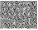
도 1은 연속적으로 침착된(serially deposited) 폴리테트라플루오로에틸렌(PTFE) 섬유 매트의 주사형 전자현미경 사진(Scanning Electron Micrograph, SEM)(950X)이다.
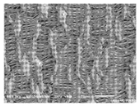
도 2는 발포 폴리테트라플루오로에틸렌(ePTFE) 매트의 주사형 전자현미경 사진(SEM)(950X)이다.
도 3a는 의료 기구의 절개 사시도이다.
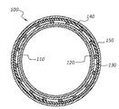
도 3b는 도 3a의 의료 기구의 선 3B-3B를 따라 취한 단면도이다.
도 3c는 도 3a의 의료 기구의 층들을 도시하는 단면도이다.
도 4는 신체 내강(lumen) 내에 배치된 도 3a의 의료 기구의 단면 개략도이다.
도 5는 스텐트-그래프트(stent-graft)를 위한 스캐폴딩 구조물의 사시도이다.BRIEF DESCRIPTION OF THE DRAWINGS The embodiments disclosed herein will become more fully apparent from the following description taken in conjunction with the accompanying drawings and the appended claims. These drawings show only typical embodiments, which will be explained in more detail and detail through the use of the accompanying drawings.
Figure 1 is a scanning electron micrograph (SEM) (950X) of a serially deposited polytetrafluoroethylene (PTFE) fiber mat.
Figure 2 is a scanning electron micrograph (SEM) (950X) of a foamed polytetrafluoroethylene (ePTFE) mat.
Fig. 3A is an exploded perspective view of the medical instrument.
FIG. 3B is a cross-sectional view taken along
Figure 3c is a cross-sectional view showing the layers of the medical device of Figure 3a.
Figure 4 is a schematic cross-sectional view of the medical instrument of Figure 3a disposed within a body lumen.
Figure 5 is a perspective view of a scaffolding structure for a stent-graft.
의료 기구는 다양한 목적을 위해 다양한 신체 내강에 배치될 수 있다. 스텐트 및/또는 스텐트-그래프트는, 예를 들어, 혈관 계통에서, 그 계통의 내강 내의 폐색의 치료를 포함한 다양한 치료 목적을 위해 배치될 수 있다. 본 발명은 중심 정맥("CV") 시스템, 말초 혈관("PV") 스텐트, 복부 대동맥류("AAA") 스텐트, 기관지 스텐트, 식도 스텐트, 담관 스텐트, 관상 동맥 스텐트, 위장 스텐트, 신경계 스텐트, 흉부 대동맥 엔도그래프(endograph), 또는 임의의 다른 스텐트 또는 스텐트-그래프트를 위해 설계된 스텐트, 스텐트-그래프트, 또는 기타 의료 기구에 적용가능할 수 있다. 또한, 본 발명은 그래프트, 션트(shunt) 등과 같은 다른 보철물에도 동일하게 적용가능할 수 있다. 게다가, 종방향 길이의 일부분이 예를 들어 금속 스캐폴드에 의해 보강된, 그리고 종방향 길이의 일부분이 스캐폴드를 전혀 갖지 않는, 연속 내강을 포함하는 의료 기구도 또한 본 발명의 범주 내에 있다. 본 명세서에 기술된 재료로 구성된 임의의 의료 기구는 혈관, 두개, 흉부, 폐, 식도, 복부 또는 안구 응용을 포함한 신체의 다양한 영역 내에서의 사용 또는 이식을 위해 구성될 수 있다. 본 발명의 범주 내에 있는 의료 기구의 예는 스텐트, 혈관 그래프트, 스텐트-그래프트, 심혈관 패치, 재건 조직 패치, 탈장 패치, 일반 외과용 패치, 심장 판막, 봉합사, 치과 재건 조직, 의료 장치 덮개(covering) 및 코팅, 위장 장치, 혈액 필터, 인공 장기, 안구 이식물, 및 폐 스텐트를 포함한 폐 장치를 포함하지만, 이에 한정되지 않는다. 편의상, 이하에 포함되는 많은 구체적인 예는 스텐트-그래프트를 언급한다. 특정 의료 기구들 중 임의의 것이 아래의 예 또는 개시내용에 언급되어 있음에도 불구하고, 본 개시내용 및 예는 임의의 보철물 또는 다른 의료 기구에 유사하게 적용될 수 있다.Medical devices can be placed in various body lumens for various purposes. Stents and / or stent-grafts can be deployed for various therapeutic purposes, including, for example, in the vascular system, including the treatment of occlusions in the lumen of the system. The present invention relates to a method for the treatment of a central venous ("CV") system, peripheral vasculature ("PV") stent, abdominal aortic aneurysm ("AAA") stent, bronchial stent, esophageal stent, bile duct stent, coronary stent, A stent-graft, or other medical device designed for a thoracic aortic endography, or any other stent or stent-graft. In addition, the present invention is equally applicable to other prostheses such as grafts, shunts, and the like. In addition, medical devices that include a continuous lumen where a portion of the longitudinal length is reinforced, for example, by a metal scaffold, and a portion of the longitudinal length has no scaffold, is also within the scope of the present invention. Any medical device constructed of the materials described herein may be configured for use or implantation in various areas of the body including blood vessel, craniofacial, pulmonary, esophagus, abdominal or ocular applications. Examples of medical devices within the scope of the present invention include but are not limited to stents, vascular grafts, stent-grafts, cardiovascular patches, reconstructive patches, hernia patches, general surgical patches, heart valves, sutures, And closures including, but not limited to, coatings, gastrointestinal devices, blood filters, artificial organs, ocular implants, and waste stents. For convenience, many of the specific examples included below refer to a stent-graft. Although any of the specific medical devices are mentioned in the examples or the disclosure below, the present disclosure and examples may be applied analogously to any prosthesis or other medical device.
본 명세서에서 사용되는 바와 같이, 스텐트 및 스텐트-그래프트라는 용어는 신체 구조 내에서, 예컨대 신체 내강 내에서 사용하도록 구성된 의료 기구를 지칭한다. 스텐트 또는 스텐트-그래프트는 스캐폴딩 또는 지지 구조물, 예컨대 프레임, 및/또는 덮개를 포함할 수 있다.As used herein, the terms stent and stent-graft refer to a medical device that is configured for use within the body structure, e.g., within the body lumen. The stent or stent-graft may include a scaffolding or support structure, such as a frame, and / or a cover.
본 명세서에서 일반적으로 기술되고 도면에 도시된 바와 같은 실시예들의 구성요소는 아주 다양한 다른 구성으로 배열되고 설계될 수 있음을 쉽게 이해할 것이다. 따라서, 도면들에 나타낸 바와 같이, 다양한 실시예들에 대한 이하의 보다 상세한 설명은 본 발명의 범주를 제한하려는 것이 아니라, 단지 다양한 실시예들을 대표하는 것이다. 실시예들의 다양한 태양이 도면에 제시되어 있지만, 도면은 구체적으로 지시되지 않는 한 반드시 축척대로 도시되지는 않는다.It will be readily appreciated that the components of the embodiments as generally described herein and illustrated in the figures may be arranged and designed in a wide variety of different configurations. Thus, as shown in the drawings, the following more detailed description of various embodiments is not intended to limit the scope of the invention, but merely as a representation of various embodiments. Although various aspects of the embodiments are shown in the drawings, the drawings are not necessarily drawn to scale unless specifically indicated.
"~에 결합된(coupled to)" 및 "~과 연통하는(in communication with)"이라는 어구는 기계적, 전기적, 자기적, 전자기적, 유체, 및 열적 상호작용을 포함하여 둘 이상의 개체들 간의 임의의 상호작용 형태를 지칭한다. 2개의 구성요소는 이들이 서로 직접 접촉하지 않더라도 서로 결합될 수 있다. 예를 들어, 2개의 구성요소는 중간 구성요소를 통해 서로 결합될 수 있다.The phrase " coupled to "and " in communication with" refers to any combination of two or more entities, including mechanical, electrical, magnetic, electromagnetic, fluid, Lt; / RTI > The two components can be coupled together even if they are not in direct contact with each other. For example, the two components may be coupled to each other through an intermediate component.
"근위(proximal)" 및 "원위(distal)"라는 방향성 용어는 본 명세서에서 스텐트 또는 다른 의료 기구 상의 반대 위치를 지칭하는데 사용된다. 기구의 근위 단부는 기구가 의사에 의해 사용되고 있는 배치 장치 내에 배치될 때 의사에게 가장 가까운 단부로서 정의된다. 원위 단부는 기구의 종방향을 따라 근위 단부의 반대편에 있는 단부, 또는 의사로부터 가장 먼 단부이다. 본 기술 분야에서 사용되는 바와 같이, 이러한 용어는 기구가 배치되면 상이한 의미를 가질 수 있음(즉, "근위" 단부는 응용에 따라 환자의 머리 또는 심장에 가장 가까운 단부를 지칭할 수도 있음)을 이해해야 한다. 일관성을 위해, 본 명세서에서 사용되는 바와 같이, "근위" 및 "원위"로 라벨링된 단부들은 기구의 배치 여부와 상관없이 동일하게 유지된다.Directional terms "proximal" and "distal" are used herein to refer to opposite positions on a stent or other medical device. The proximal end of the instrument is defined as the end closest to the surgeon when the instrument is placed in a deployment device being used by the physician. The distal end is the end opposite the proximal end along the longitudinal direction of the instrument, or the end farthest from the surgeon. As used in the art, it should be understood that such terms may have different meanings when the device is deployed (i. E., The "proximal" end may refer to the end closest to the patient's head or heart, depending on the application) do. For consistency, as used herein, ends labeled "proximal" and "distal" remain the same whether or not the instrument is deployed.
스텐트 또는 스텐트-그래프트의 종방향은 일반적으로 관형인 스텐트 또는 스텐트-그래프트의 축을 따르는 방향이다. 기구가 중합체 층과 같은 필름 또는 시트형 구성요소의 하나 이상의 층에 결합된 금속 와이어 구조물로 구성되는 실시예에서, 금속 구조물은 "스캐폴딩" 또는 "프레임"으로 지칭되며, 중합체 층은 "덮개" 또는 "코팅"으로 지칭된다. "덮개" 및 "코팅"이라는 용어는 중합체의 단일 층, 동일한 중합체의 다수의 층, 또는 조합하여 사용되는 별개의 중합체를 포함하는 층들을 지칭할 수 있다. 또한, 본 명세서에서 사용되는 바와 같이, "덮개" 및 "코팅"이라는 용어는 단지 스캐폴드의 일부분에 결합된 층들 또는 층만을 지칭하며; 어느 용어도 전체 스캐폴드가 "덮여"있거나 "코팅"되어야 할 것을 필요로 하지 않는다. 다시 말해, 스캐폴드의 일부분이 덮일 수 있고 일부분이 노출된 채로 남아있을 수 있는 의료 기구가 본 발명의 범주 내에 있다. 최종적으로, 덮개 또는 코팅과 관련하여 열거된 임의의 개시내용은 연관된 프레임 또는 다른 구조물이 없는 하나 이상의 "덮개" 층을 포함하는 의료 장치에 유사하게 적용될 수 있다. 예를 들어, 본 명세서에서 기술된 재료들 중 임의의 재료를 "코팅" 또는 "덮개"로서 포함하는 탈장 패치는 패치가 프레임 또는 다른 구조물을 추가로 포함하는지 여부에 관계없이 본 발명의 범주 내에 있다. 유사하게, 관형 그래프트 또는 션트는, 연관된 스캐폴딩 구조물이 없는, 본 명세서에 열거된 덮개 또는 적층 재료로 구성될 수 있다.The longitudinal direction of the stent or stent-graft is generally the direction along the axis of the stent or stent-graft that is tubular. In embodiments where the device is comprised of a metal wire structure that is bonded to one or more layers of a film or sheet-like component, such as a polymer layer, the metal structure is referred to as a "scaffolding" or "frame" Quot; coating ". The terms "cover" and "coating" may refer to layers comprising a single layer of polymer, multiple layers of the same polymer, or separate polymers used in combination. In addition, as used herein, the terms "cover" and "coating" refer only to only the layers or layers bonded to a portion of the scaffold; None of the terms require that the entire scaffold be "covered" or "coated". In other words, a medical device is within the scope of the present invention in which a portion of the scaffold can be covered and a portion can remain exposed. Finally, any disclosure enumerated with respect to cover or coating may be similarly applied to a medical device comprising one or more "cover" layers without an associated frame or other structure. For example, a hernia patch that includes any of the materials described herein as a "coating" or "cover " is within the scope of the invention regardless of whether the patch further comprises a frame or other structure . Similarly, a tubular graft or shunt may be constructed of a cover or laminate material listed herein without an associated scaffolding structure.
의료 장치 덮개는 연속적으로 적용될 수 있는 2개 이상의 층으로 구성된 다층 구조물을 포함할 수 있다. 또한, 다층 구조물은 비균질 층을 포함할 수 있는데, 이는 인접한 층들이 상이한 특성을 갖는다는 것을 의미한다. 따라서, 본 명세서에서 사용되는 바와 같이, 다층 구조물의 각각의 층은, 층들의 별개의 적용 또는 층들 사이의 상이한 특성들로 인해, 별개의 층을 포함할 수 있다. 층들이 그들의 위치, 구조 또는 기능에 의해 식별될 수 있으므로, 개별 층은 반드시 단일 재료 또는 단일 미세 구조만을 포함할 필요가 없을 수 있다.The medical device lid may comprise a multi-layer structure comprised of two or more layers that can be applied continuously. In addition, the multi-layer structure may comprise a heterogeneous layer, which means that adjacent layers have different properties. Thus, as used herein, each layer of a multi-layered structure may comprise a separate layer, either because of different applications of the layers or due to different properties between the layers. As the layers can be identified by their location, structure or function, the individual layers may not necessarily need to contain only a single material or a single microstructure.
게다가, 본 명세서에서 사용되는 바와 같이, "조직 내성장(tissue ingrowth)" 및 "세포 침투"는 의료 기구의 구성요소 내로의 생물학적 또는 체내 물질의 임의의 존재 또는 침투를 지칭한다. 예를 들어, 의료 기구의 층 또는 구성요소의 개구 또는 기공 내의 신체 조직(예를 들어, 콜라겐, 세포 등)의 존재는 그 구성요소 내로의 조직 내성장을 포함한다. 또한, 본 명세서에서 사용되는 바와 같이, 의료 기구의 구성요소에 대한 조직의 "부착"은 간접적인 접합을 포함하여 기구에 대한 조직의 임의의 접합 또는 접착을 지칭한다. 예를 들어, 어떤 종류의 조직(예를 들어, 콜라겐)은 스텐트 덮개에 부착(조직 내성장을 통한 부착을 포함함)될 수 있고, 생물학적 물질의 다른 층(예컨대, 내피 세포)이 차례로 제1 조직에 접착될 수 있다. 그러한 경우에, 제2 생물학적 물질(본 예에서는 내피 세포) 및 조직(본 예에서는 콜라겐)이 스텐트 덮개에 "부착"된다.In addition, as used herein, "tissue ingrowth" and "cell penetration" refer to any presence or infiltration of a biological or biological material into a component of a medical device. For example, the presence of body tissues (e.g., collagen, cells, etc.) in the openings or pores of a layer or component of a medical device involves intratracheal growth into its components. In addition, as used herein, "adherence" of a tissue to a component of a medical device refers to any bonding or adherence of tissue to the device, including indirect bonding. For example, some types of tissue (e.g., collagen) can be attached to the stent cover (including attachment through growth in tissue) and other layers of biological material (e.g., endothelial cells) Can be adhered to the tissue. In such a case, a second biological material (in this example endothelial cells) and tissue (in this example collagen) is "attached" to the stent lid.
다공성 재료는 재료의 기공 크기에 기초하여 다양한 입자 또는 생물학적 요소에 대해 선택적으로 투과성일 수 있다. 예를 들어, 20 마이크로미터 미만의 기공 크기를 갖는 재료는 이물 거대 세포(foreign body giant cell)와 같은 20 마이크로미터 초과의 세포 유형에 대해 불투과성일 수 있다. 유사하게, 8 마이크로미터 미만의 기공 크기를 갖는 재료는 적혈구와 같은 다른 세포 유형에 의한 침투에 대해 불투과성일 수 있다. 일부 실시예에서, 8 마이크로미터 미만의 또는 6 마이크로미터 미만의 (예를 들어, 0 내지 8 마이크로미터 사이의 임의의 값을 포함하는) 기공 크기를 갖는 재료가 적혈구에 대해 불투과성일 수 있다.The porous material may be selectively permeable to various particles or biological elements based on the pore size of the material. For example, a material having a pore size of less than 20 micrometers may be impermeable to cell types greater than 20 micrometers, such as foreign body giant cells. Similarly, a material having a pore size of less than 8 micrometers may be impermeable to penetration by other cell types such as red blood cells. In some embodiments, a material having a pore size of less than 8 micrometers or less than 6 micrometers (including, for example, any value between 0 and 8 micrometers) may be impermeable to red blood cells.
본 명세서에서 사용되는 바와 같이, 세포 불투과도는 장벽을 가로지르는 임의의 세포 이동의 완전한 배제를 요구하지 않는다. 예를 들어, 적은 수의 적혈구가 재료를 가로지를 수 있다고 하더라도, 재료는 적혈구 이동에 대해 불투과성일 수 있다. 따라서, 재료는 세포 불투과도의 정의를 만족시키면서 재료를 가로지르는 세포 이동을 실질적으로 억제하도록 구성될 수 있다.As used herein, cellular impermeability does not require complete elimination of any cell migration across the barrier. For example, even though a small number of red blood cells can cross the material, the material may be impermeable to red cell migration. Thus, the material can be configured to substantially inhibit cell migration across the material while satisfying the definition of cellular impermeability.
본 명세서에서 사용되는 바와 같이, 적혈구 불투과성 재료는 적혈구의 경벽(transmural) 이동을 실질적으로 억제하는 재료이다. 또한, 본 명세서에서 사용되는 바와 같이, 적혈구의 경벽 이동을 실질적으로 억제한다는 것은, 생물학적 압력 하에서(예컨대, 신체에 이식된 경우), 재료 벽과 접촉하는 적혈구 중 0.1% 미만이 재료 벽을 가로질러 이동할 것이라는 것을 의미한다. 따라서, 이러한 정의에는 모든 그러한 세포의 완전한 제한을 요구함이 없이 대다수의 적혈구의 경벽 이동을 억제하는 재료가 포함된다. 일부 경우에, 6 마이크로미터 미만의 기공 크기를 포함하여 8 마이크로미터 미만의 기공 크기를 갖는 재료, 또는 0 내지 8 마이크로미터 사이의 임의의 값의 기공 크기를 갖는 재료가 적혈구의 경벽 이동에 대해 불투과성일 수 있다. 다른 재료, 예를 들어, 상이한 기공 크기의 개별 층을 갖는 복합 재료가, 마찬가지로, 적혈구의 경벽 이동에 대해 불투과성일 수 있다.As used herein, erythropoietic material is a material that substantially inhibits the transmural movement of erythrocytes. Also, as used herein, substantially inhibiting the migration of erythrocytes into the blood is meant that less than 0.1% of the erythrocytes in contact with the material wall under biological pressure (e.g., when implanted in the body) It will move. Thus, this definition includes materials that inhibit the migration of the majority of erythrocytes without requiring complete restriction of all such cells. In some cases, a material having a pore size of less than 8 micrometers, including a pore size of less than 6 micrometers, or a material having a pore size of any value between 0 and 8 micrometers, May be transmissive. Composite materials having discrete layers of different materials, e.g., different pore sizes, may likewise be impermeable to the radial movement of erythrocytes.
일부 경우에, 6 또는 8 마이크로미터 초과의 다공도를 갖는 층은, 더 구불구불한 경벽 경로를 생성하기 위해 추가 층과 조합될 때, 단일 층이 8 마이크로미터 미만의 다공도를 갖지 않더라도, 조합된 층을 가로지르는 적혈구의 경벽 이동에 대해 불투과성일 수 있다.In some cases, a layer having a porosity of greater than 6 or 8 micrometers will have a porosity of less than 8 micrometers when combined with an additional layer to produce a further serpentine piercing path, Lt; RTI ID = 0.0 > RBC < / RTI >
게다가, 다양한 다공도의 다양한 층을 포함하는 복합 구조물은 적혈구의 경벽 이동에 대해 불투과성일 수 있다. 일부 실시예에서, 실질적으로 비다공성인 층에 결합된 다양한 다공도의 층으로 구성된 구조물은 적혈구의 경벽 이동에 대해 불투과성일 수 있다.In addition, composite structures comprising various layers of varying degrees of porosity may be impermeable to the migration of the red blood cells into the pores. In some embodiments, structures composed of layers of varying degrees of porosity bonded to a layer that is substantially non-porous may be impermeable to the migration of erythrocytes into the pores.
더욱이, 본 발명의 범주 내의 구조물은 임의의 세포 유형에 대해 세포 불투과성일 수 있으며, 이는 구조물과 접촉하는 세포 중 0.1% 미만(세포 유형에 관계없이)이 구조물 벽을 가로질러 이동할 것이라는 것을 의미한다. 유사하게, 본 발명의 범주 내의 구조물은 조직 불투과성일 수 있으며, 이는 구조물과 접촉하는 조직의 질량 또는 부피의 0.1% 미만이 구조물 벽을 가로질러 이동할 것이라는 것을 의미한다.Moreover, structures within the scope of the present invention may be cell impermeable to any cell type, meaning that less than 0.1% (regardless of cell type) of cells in contact with the construct will migrate across the structure wall . Similarly, structures within the scope of the present invention may be tissue impermeable, meaning that less than 0.1% of the mass or volume of tissue in contact with the structure will migrate across the structure wall.
일례에서, 세포 불투과성 관형 다층 구조물을 30일 동안 동물 숙주에 이식하였다. 다층 구조물의 분리 시, 측정가능한 양의 조직이 구조물의 내강 표면 상에 존재하지 않았다. 따라서, 측정가능한 경벽 세포 또는 조직 이동이 없는 상태로 30일 동안 동물 숙주에 이식된 재료는 본 명세서에서 사용된 그들 용어들과 같이 세포 및 조직 불투과성이다. 또한, 표준 ePTFE 스텐트-그래프트가 유사하게 이식되었을 때 내강 표면 상에 조직 성장을 보였음이 관찰되었다.In one example, a cell-impermeable tubular multilayer structure was implanted into an animal host for 30 days. Upon separation of the multi-layered structure, no measurable amount of tissue was present on the luminal surface of the structure. Thus, materials implanted into an animal host for 30 days in the absence of measurable radial cell or tissue migration are cell and tissue impermeable, as are their terms used herein. It was also observed that tissue growth was observed on the luminal surface when a standard ePTFE stent-graft was similarly implanted.
게다가, 재료 또는 구조물은 재료 벽을 가로지르는 유체 통과에 대해 불투과성일 수 있다. 0.5 마이크로미터 미만의 기공 크기를 갖는 재료 또는 층은, 본 명세서에서, 유체 통과에 대해 불투과성이거나 또는 재료 또는 층을 가로질러 유체 불투과성인 것으로 언급된다.In addition, the material or structure may be impermeable to fluid passing across the material wall. A material or layer having a pore size of less than 0.5 micrometers is referred to herein as being impermeable to fluid passage or fluid impermeable across a material or layer.
상기 실시예 중 임의의 것과 연관된 기공 크기는 하기에 추가로 정의되는 바와 같은 평균 기공 크기를 지칭할 수 있다. 그것은 또한 직접 측정 기법에 의해 결정된 기공 크기를 지칭할 수도 있다. 본 명세서에서 사용되는 바와 같은 "일반적으로" 및 "실질적으로"라는 용어는 파라미터가 기준 파라미터의 5% 이내임을 나타낸다. 따라서, 일반적으로 동등한 것으로 지칭되는 2개의 양들은 서로의 5% 이내이다. 게다가, 일반적으로 또는 실질적으로 불투과성인 멤브레인(membrane)은 단지 상기 정의된 기공 크기로부터 5%까지만 변한다.The pore size associated with any of the above embodiments may refer to the average pore size as further defined below. It may also refer to pore size determined by direct measurement techniques. The terms "generally" and "substantially" as used herein indicate that the parameter is within 5% of the reference parameter. Thus, the two quantities generally referred to as equivalent are within 5% of each other. In addition, a membrane that is generally or substantially impermeable only varies from 5% above the defined pore size.
순환계 내의 내강은 일반적으로 단일 층(모노 층)의 내피 세포로 라이닝되어 있다. 내피 세포의 이러한 라이닝이 내피를 구성한다. 내피는 순환계의 내강을 통해 유동하는 혈액과 내강의 내벽 사이의 계면으로서 작용한다. 내피는, 다른 기능들 중에서도 특히, 내강 내의 난류성 혈류를 감소시키거나 방지한다. 내피는, 죽상경화증을 포함하여 혈관 생물학의 많은 태양들에서 역할을 하여, 내강 주위에 선택적 장벽을 만들고, 혈액 응고, 염증, 혈관 형성, 혈관 수축 및 혈관 확장을 일으킨다.The lumen in the circulatory system is generally lined with endothelial cells of a monolayer (mono layer). These lining of endothelial cells make up the endothelium. The endothelium acts as the interface between the blood flowing through the lumen of the circulatory system and the inner wall of the lumen. The endothelium, in particular among other functions, reduces or prevents turbulent blood flow in the lumen. Endothelium plays a role in many aspects of vascular biology, including atherosclerosis, creating a selective barrier around the lumen, causing blood clotting, inflammation, angiogenesis, vasoconstriction, and vasodilation.
다공성 또는 반-다공성 재료의 덮개를 포함하는 치료용 의료 기구는 의료 장치의 혈액 접촉면의 다공성 표면 상에 내피 층의 형성을 허용할 수 있다. 표면 상에 내피 층을 형성하거나 내피화되면 이식된 장치의 생체적합성이 증가될 수 있다. 예를 들어, 스텐트의 내경(혈액 접촉 표면) 상에 내피의 형성을 허용하는 스텐트는 치료 영역에서의 치유를 추가로 촉진할 수 있고/있거나 장기간의 존립 가능성(viability)을 가질 수 있다. 예를 들어, 내피 세포로 코팅된 스텐트는 주변 신체 내강과 보다 일치할 수 있어, 그에 의해 난류성 혈류가 적어지거나 혈전증 또는 혈전 형성의 위험이 감소될 수 있다. 따라서, 스텐트의 내측 표면 상에 내피 층의 형성을 허용하는 스텐트 또는 스텐트-그래프트는 특히 생체적합성일 수 있어서, 적용 지점에서의 외상이 줄어들고/들거나, 부작용이 더 감소하고/하거나, 장기간의 장치 존립 가능성을 가져올 수 있다. 다공성 또는 반-다공성 재료의 덮개를 포함하는 의료 기구는, 예를 들어, 의료 기구의 조직 접촉면에 대한 신체에 의한 염증 반응을 억제 또는 감소시키도록 구성될 수 있다. 의료 기구에 대한 신체의 염증 반응과 같은 메커니즘은 신생 내막 증식(neointimal hyperplasia)과 같은 부정적인 결과를 자극, 악화 또는 촉진할 수 있다. 예를 들어, 장치의 혈액 접촉면 상으로의 조직 내성장 및/또는 내피 세포의 성장 또는 부착을 허용하도록 구성된 장치는 부정적인 유동 특징 및 혈액 응고의 가능성을 감소시킬 수 있다. 유사하게, 이와 같이 구성된 장치는, 예를 들어 장치의 조직 접촉면 상의 재료에 대한 신체의 염증 반응을 완화시킬 수 있다. 유발된 염증 반응을 조절함으로써, 생체활성 염증성 대식 세포 및 이물 거대 세포의 존재와 같은 부정적인 결과가 감소될 수 있다. 이것은 신생 내막 증식을 자극하는 사건 및 장치를 둘러싸는 섬유질 캡슐 형성을 촉진할 수 있는 화학적 연쇄 반응을 최소화하는 데 도움을 줄 수 있다.Therapeutic medical devices comprising a cover of porous or semi-porous material may permit formation of an endothelial layer on the porous surface of the blood contacting surface of the medical device. The formation of an endothelial layer on the surface or the endothelialization may increase the biocompatibility of the implanted device. For example, a stent that allows the formation of an endothelium on the inner diameter (blood contacting surface) of the stent may further promote healing in the treatment area and / or may have long term viability. For example, a stent coated with endothelial cells may be more consistent with the surrounding body lumen, thereby reducing turbulent blood flow or reducing the risk of thrombosis or thrombus formation. Thus, a stent or stent-graft that allows the formation of an endothelial layer on the inner surface of the stent may be particularly biocompatible, so that trauma at the point of application may be reduced and / or adverse effects may be further reduced and / It can bring about a possibility. A medical device comprising a cover of a porous or semi-porous material may be configured to inhibit or reduce the body's inflammatory response to, for example, the tissue contacting surface of the medical device. Mechanisms such as the body's inflammatory response to a medical device can stimulate, aggravate, or promote negative consequences such as neointimal hyperplasia. For example, an apparatus configured to allow tissue growth and / or endothelial cell growth or attachment onto the blood contact surface of the device may reduce negative flow characteristics and the likelihood of blood coagulation. Similarly, the device thus configured can alleviate the body's inflammatory response to, for example, the material on the tissue-contacting surface of the device. By controlling the induced inflammatory response, negative consequences such as the presence of bioactive inflammatory macrophages and foreign giant cells can be reduced. This can help to minimize the chemical chain reaction that can promote fibrous capsule formation surrounding events and devices that stimulate new endometrial proliferation.
본 명세서에 기술된 것과 같은 연속적으로 침착된 섬유, 예컨대 회전 방사 또는 전기 방사 재료는 스텐트, 패치, 그래프트 등과 같은 의료 기구의 부분을 구성하는 데 사용될 수 있다. 본 발명은, 이하에 포함되는 임의의 특정 예들에도 불구하고, 임의의 이식가능한 의료 기구에 적용가능하다. 다시 말해, 스텐트 또는 패치와 같은 특정 의료 기구가 하기의 개시내용 및 예에서 참조될 수 있지만, 본 발명은 또한 중합체 재료의 덮개 또는 층을 포함하는 것들과 같은 다른 의료 기구에도 유사하게 적용가능하다.Successively deposited fibers such as those described herein, such as rotating or electrospun materials, can be used to construct portions of a medical device such as a stent, patch, graft, and the like. The present invention is applicable to any implantable medical device, notwithstanding any of the specific examples contained below. In other words, although certain medical devices such as stents or patches may be referred to in the following disclosure and examples, the present invention is also similarly applicable to other medical devices, such as those that include a cover or layer of polymeric material.
일부 실시예에서, 연속적으로 침착된 나노 섬유(및/또는 마이크로 섬유)는 내피 세포, 적혈구, 콜라겐 등과 같은 나노 스케일(및/또는 마이크로 스케일) 신체 구조물과의 상호작용을 허용하도록 구성될 수 있다.In some embodiments, the subsequently deposited nanofibers (and / or microfibers) can be configured to allow interaction with nanoscale (and / or microscale) body structures such as endothelial cells, red blood cells, collagen, and the like.
의료 기구는 2개 이상의 층 또는 재료를 포함할 수 있다. 이들 층은, 단독으로 또는 조합하여, 전체 구조물에 다양한 특성을 부여하도록 설계되거나 구성될 수 있다. 예를 들어, 하나 이상의 층, 및/또는 조합된 특징의 둘 이상의 층은 인장 강도, 파열(burst) 강도, 유연성, 후프 강도, 반경방향 압축에 대한 저항 등과 같은 전체 구조물의 구조적 특성을 제어할 수 있다. 유사하게, 하나 이상의 층, 및/또는 조합된 특징의 둘 이상의 층은 의료 기구의 생체적합성을 제어할 수 있다. 예를 들어, 다공도, 유체 투과도, 세포 투과도 등은 모두 환자 신체 내에 배치된 의료 기구에 대한 생물학적 반응에 영향을 줄 수 있다.The medical device may include two or more layers or materials. These layers, alone or in combination, may be designed or constructed to impart various properties to the entire structure. For example, one or more layers and / or two or more layers of combined features can control the structural properties of the overall structure, such as tensile strength, burst strength, flexibility, hoop strength, resistance to radial compression, have. Similarly, one or more layers, and / or two or more layers of combined features, can control the biocompatibility of the medical device. For example, porosity, fluid permeability, and cellular permeability all can affect the biological response to medical devices deployed within the patient ' s body.
의료 기구 및 관련 구성요소를 비롯한 다양한 구조물은 연속적으로 침착된 섬유를 포함할 수 있다. 연속적으로 침착된 섬유는 중합체 섬유, 세라믹 섬유 및/또는 다른 재료를 포함할 수 있다. 일부 실시예에서, 연질 또는 유동성 재료가 콜렉터 또는 기재 상의 기다란 스트랜드 또는 섬유에 침착된다. 이들 섬유가 침착된 후에, 섬유의 매트 또는 격자의 형상 또는 구조는, 예를 들어 섬유의 재료의 경화에 의해 고정될 수 있다. 예를 들어, 중합체 재료가 중합체 분산액 형태의 섬유로서 침착되고, 이어서 가열되어 분산액의 용매 성분을 제거하고 중합체 섬유의 구조를 고정시킬 수 있다. 유사하게, 중합체 재료는 가열되거나 용융된 상태에 있는 동안 섬유로서 연속적으로 침착될 수 있다. 수집된 섬유의 냉각은 섬유의 매트 또는 격자의 구조를 고정시키려는 경향이 있을 수 있다. 이들 매트 또는 격자를 포함하는 섬유는 일반적으로 마이크로 스케일(직경이 1 마이크로미터와 1 밀리미터 사이인 섬유) 및/또는 일반적으로 나노 스케일(직경이 1 마이크로미터 미만인 섬유)일 수 있다. 도 1은 예시적인 연속적으로 침착된 섬유 매트의 SEM(950X)이다. 도 1의 매트의 섬유는 폴리테트라플루오로에틸렌(PTFE)의 회전 방사에 의해 침착되었다.Various structures, including medical devices and related components, may include fibers that have been continuously deposited. The subsequently deposited fibers may comprise polymeric fibers, ceramic fibers, and / or other materials. In some embodiments, a soft or flowable material is deposited on the elongated strands or fibers on the collector or substrate. After these fibers are deposited, the shape or structure of the mat or grid of the fibers can be fixed, for example, by curing the material of the fibers. For example, the polymeric material may be deposited as a fiber in the form of a polymer dispersion, and then heated to remove the solvent component of the dispersion and fix the structure of the polymeric fibers. Similarly, the polymeric material can be continuously deposited as fibers while in a heated or molten state. Cooling of the collected fibers may tend to fix the structure of the mat or grid of the fibers. The fibers comprising these mats or gratings may generally be microscale (fibers having a diameter between 1 micrometer and 1 millimeter) and / or generally nanoscale (fibers having a diameter less than 1 micrometer). Figure 1 is an SEM (950X) of an exemplary continuously deposited fiber mat. The fibers of the mat of Figure 1 were deposited by spinning spinning of polytetrafluoroethylene (PTFE).
연속적으로 침착된 섬유 매트 또는 격자는 콜렉터 상에, 기재 상에, 베이스 재료 상에, 및/또는 이전에 침착된 섬유 상에 연속적으로 침착된 섬유로 적어도 부분적으로 구성되는 구조물을 지칭한다. 일부 경우에, 섬유는 무작위로 배치될 수 있지만, 다른 실시예에서는 섬유의 정렬 또는 배향이 다소 제어되거나 일반적인 추세 또는 패턴을 따를 수 있다. 임의의 섬유 정렬 패턴 또는 정도에 관계없이, 섬유가 콜렉터, 기재, 베이스 재료 및/또는 이전에 침착된 섬유 상에 침착되기 때문에, 섬유는 직조되지 않고 오히려 연속적으로 침착된다. 그러한 섬유가 다양한 구조물을 생성하도록 구성되기 때문에, 본 명세서에서 사용되는 바와 같이, "매트" 및 "격자"라는 용어는 튜브, 구(sphere), 시트 등을 포함하여 임의의 그러한 구조물을 지칭하는 것으로 폭넓게 해석되는 것으로 의도된다. 또한, 본 명세서에서 사용되는 바와 같은 "멤브레인"이라는 용어는 멤브레인의 적어도 하나의 다른 치수보다 더 작은 두께를 갖는 연속적으로 침착된 섬유를 포함하는 임의의 구조물을 지칭한다. 멤브레인의 예로는 시트, 스트립, 튜브, 구, 커버, 층 등을 형성하는 연속적으로 침착된 섬유 매트 또는 격자를 포함하지만 이에 한정되지는 않는다.A continuously deposited fiber mat or lattice refers to a structure that is at least partially composed of fibers that are continuously deposited on a collector, on a substrate, on a base material, and / or on previously deposited fibers. In some cases, the fibers may be randomly arranged, but in other embodiments the alignment or orientation of the fibers may be somewhat controlled or follow a general trend or pattern. Regardless of the fiber alignment pattern or degree, the fibers are not woven, but rather are continuously deposited, because the fibers are deposited on the collector, substrate, base material and / or previously deposited fibers. As used herein, the term " mat "and" grid "refer to any such structure, including tubes, spheres, sheets, etc., as such fibers are constructed to produce various structures And is intended to be broadly construed. In addition, the term "membrane" as used herein refers to any structure comprising a continuously deposited fiber having a thickness less than at least one other dimension of the membrane. Examples of membranes include, but are not limited to, continuously deposited fibrous mats or grids that form sheets, strips, tubes, spheres, covers, layers, and the like.
회전 방사는 재료가 섬유로서 연속적으로 침착될 수 있는 방법의 일례이다. 회전 방사 공정의 일 실시예는 방적 돌기의 외주연부 상에 오리피스를 갖도록 구성된 컵 또는 방적 돌기 내로 중합체 용액 또는 분산액을 로딩하는 것을 포함한다. 이어서, 방적 돌기를 회전시켜, 방적 돌기 내의 유동성 재료가 (예를 들어, 원심력 및 유체정력학적 힘의 조합을 통해) 오리피스로부터 배출될 수 있게 한다. 이어서, 재료는 재료의 스트림이 작은 직경의 섬유로 신장될 수 있게 하는 경향이 있는 항력(drag force)을 가지고 오리피스로부터 연장되는 "제트(jet)" 또는 "스트림"을 형성할 수 있다. 이어서, 섬유는 수집 장치, 기재, 또는 다른 섬유 상에 침착될 수 있다. 일단 수집되면, 섬유는 건조되거나, 냉각되거나, 소결되거나, 달리 처리되어 구조를 고정시키거나 그렇지 않으면 섬유 매트를 경화시킬 수 있다. 예를 들어, 분산액으로부터 회전 방사된 중합체 섬유는 소결되어 용매, 섬유화제, 또는 다른 재료를 제거할 수 있을뿐만 아니라 매트의 구조를 고정시킬 수 있다. 일 실시예에서, 예를 들어, 수성 폴리테트라플루오로에틸렌(PTFE) 분산액은 폴리에틸렌 옥사이드(PEO)(섬유화제로서) 및 물(PEO용 용매로서)과 혼합될 수 있고, 그 혼합물은 회전 방사될 수 있다. 수집된 섬유를 가열하여 소결하면 PTFE 구조를 고정시키고, 물을 증발시키고, PEO를 승화시킬 수 있다. 회전 방사를 위한 예시적인 방법 및 시스템은 2013년 1월 15일자로 출원된 발명의 명칭이 "Rotational Spun Material Covered Medical Appliances and Manufacturing of Method"인 미국 특허 출원 제13/742,025호에서 찾을 수 있으며, 이는 전체적으로 본 명세서에 참고로 포함된다.Rotating radiation is an example of how a material can be continuously deposited as a fiber. One embodiment of a spinning spinning process involves loading a polymer solution or dispersion into a cup or spinneret configured to have an orifice on the outer periphery of the spinneret. The spinneret is then rotated to allow the flowable material in the spinneret to exit the orifice (e.g., through a combination of centrifugal and hydrostatic forces). The material may then form a "jet" or "stream" extending from the orifice with a drag force that tends to allow the stream of material to extend into small diameter fibers. The fibers can then be deposited on a collection device, substrate, or other fiber. Once collected, the fibers may be dried, cooled, sintered, or otherwise treated to fix the structure or otherwise cure the fiber mat. For example, the polymer fibers spinning from the dispersion may be sintered to remove the solvent, fibrous agent, or other material, as well as fix the structure of the mat. In one embodiment, for example, an aqueous polytetrafluoroethylene (PTFE) dispersion can be mixed with polyethylene oxide (PEO) (as a fibroating agent) and water (as a solvent for PEO) . Heating and sintering the collected fibers can fix the PTFE structure, evaporate the water, and sublimate the PEO. An exemplary method and system for rotational spinning can be found in U.S. Patent Application No. 13 / 742,025 entitled " Rotational Spun Material Covered Medical Appliances and Manufacturing Method "filed January 15, 2013, Which is incorporated herein by reference in its entirety.
회전 방사 공정 및 전기 방사 공정은 상이한 특징을 갖는 연속적으로 침착된 섬유 매트를 제조할 수 있다. 예를 들어, 전기 방사 공정과 비교하여, 회전 방사는 우수한 수율, 성능, 및 스케일링을 나타낼 수 있다. 회전 방사 공정은 전기 방사와 비교하여 더 나은 재현성, 신뢰성, 및 품질을 나타낼 수 있다. 다시 말해, 회전 방사된 섬유 매트는 전기 방사된 섬유 매트와 비교하여 더 근접한 허용오차 내에서 보다 일관성을 나타낼 수 있다. 회전 방사는 대형 작업으로 보다 직접적으로 스케일링 가능할 수 있다. 큰 규모의 전기 방사는 고전압, 및 시간, 비용 및 변동성을 추가로 도입하는 다른 어려움을 수반할 수 있는 반면, 회전 방사는 보다 직접적이고 간단하게 스케일링되어 보다 일관된 섬유 매트를 제조할 수 있다.Rotary spinning and electrospinning processes can produce continuously deposited fiber mats having different characteristics. For example, compared to an electrospinning process, rotating spinning can exhibit excellent yield, performance, and scaling. Rotary spinning processes can exhibit better reproducibility, reliability, and quality compared to electrospinning. In other words, a spinning fiber mat may be more consistent within closer tolerances compared to an electrospun fiber mat. Rotating radiation can be more directly scaled by large work. While large-scale electrospinning may involve additional difficulties in introducing high voltage and time, cost and variability, the rotating radiation may be more directly and simply scaled to produce a more consistent fiber mat.
전기 방사는 재료가 섬유로서 연속적으로 침착될 수 있는 방법의 다른 실시예이다. 전기 방사 공정의 일 실시예는 주사기 펌프에 결합된 주사기 내로 중합체 용액 또는 분산액을 로딩하는 것을 포함한다. 재료는 전기장이 있는 상태에서 펌프에 의해 주사기 밖으로 배출된다. 주사기로부터 배출된 재료는 섬유로 신장될 수 있으며, 이어서, 섬유는 콜렉터 또는 기재와 같은 접지된 수집 장치 상에 침착된다. 본 시스템은 주사기로부터 배출된 재료가 정전기적으로 하전되고, 그에 따라 접지된 수집 장치에 흡인(attract)되도록 구성될 수 있다. 회전 방사에서와 같이, 일단 수집되면, 섬유는 건조되거나, 냉각되거나, 소결되거나, 달리 처리되어 구조를 고정시키거나 그렇지 않으면 섬유 매트를 경화시킬 수 있다. 예를 들어, 분산액으로부터 전기 방사된 중합체 섬유는 소결되어 용매, 섬유화제, 또는 다른 재료를 제거할 수 있을뿐만 아니라 매트의 구조를 고정시킬 수 있다. 회전 방사에서와 같이, 전기 방사의 일 실시예는 PEO 및 물(PEO용 용매로서)과 혼합된 수성 PTFE 분산액을 전기 방사하는 것을 포함한다. 수집된 섬유를 가열하여 소결하면 PTFE 구조를 고정시키고, 물을 증발시키고, PEO를 승화시킬 수 있다. 의료 장치를 전기 방사하기 위한 예시적인 방법 및 시스템은, 양자 공히 2014년 3월 13일자로 출원된 발명의 명칭이 둘 모두 "Electrospun Material Covered Medical Appliances and Method of Manufacture"인 미국 특허 출원 제13/826,618호와 제13/827,790호, 및 2012년 1월 27일자로 출원된 발명의 명칭이 "Electrospun PTFE Coated Stent and Method of Use"인 미국 특허 출원 제13/360,444호에서 찾을 수 있으며, 이들 각각은 전체적으로 본 명세서에 참고로 포함된다.Electrospinning is another embodiment of a method by which a material can be deposited continuously as a fiber. One embodiment of an electrospinning process involves loading a polymer solution or dispersion into a syringe coupled to a syringe pump. The material is pumped out of the syringe by an electric field. The material discharged from the syringe may be stretched into fibers, which are then deposited on a grounded collection device such as a collector or substrate. The system may be configured such that the material discharged from the syringe is electrostatically charged and thus attracted to a grounded collection device. As in spinning, once collected, the fibers can be dried, cooled, sintered, or otherwise treated to fix the structure or otherwise cure the fiber mat. For example, the polymer fibers electrospun from the dispersion can be sintered to remove the solvent, fibrous agent, or other material, as well as fix the structure of the mat. As in rotational spinning, one embodiment of electrospinning involves electrospinning an aqueous PTFE dispersion mixed with PEO and water (as a solvent for PEO). Heating and sintering the collected fibers can fix the PTFE structure, evaporate the water, and sublimate the PEO. Exemplary methods and systems for electrospinning a medical device are disclosed in U.S. Patent Application No. 13 / 826,618, entitled " Electrospun Material Covered Medical Appliances and Methods of Manufacture, " filed March 13, No. 13 / 827,790, filed January 27, 2012, and U.S. Patent Application No. 13 / 360,444 entitled "Electrospun PTFE Coated Stent and Method of Use," filed January 27, 2012, each of which is incorporated herein by reference in its entirety Which is incorporated herein by reference.
회전 방사 및/또는 전기 방사는 연속적으로 침착된 섬유를 포함하는 다양한 재료 또는 구조물을 생성하는 데 이용될 수 있다. 다공도, 투과도, 재료 조성, 강성도, 섬유 정렬 등뿐 아니라 그러한 재료의 미세 구조 또는 나노 구조는 생체적합성을 촉진시키거나 재료와 세포 또는 다른 생물학적 물질 간의 상호작용에 영향을 주도록 제어 또는 구성될 수 있다. 다양한 재료가 회전 방사 및 전기 방사와 같은 공정을 통해 연속적으로 침착될 수 있는데: 그러한 재료에는 예를 들어, 중합체, 세라믹, 금속, 용융 처리될 수 있는 재료, 또는 연질 또는 액체 형태를 갖는 임의의 다른 재료가 있다. 재료가 용액, 분산액, 용융 또는 반용융 형태 등으로 있는 동안 회전 방사 또는 전기 방사를 통해 다양한 재료가 연속적으로 침착될 수 있다. 본 발명은 임의의 기재 상에 또는 본 명세서에서 논의된 임의의 기하 구조 내에 섬유로서 연속적으로 침착되는 것으로 본 명세서에서 논의된 임의의 재료에 적용가능할 수 있다. 따라서, 본 명세서에서 주어진 특정 재료 또는 구조의 예는 다른 재료 및/또는 구조에 유사하게 적용될 수 있다.Rotating radiation and / or electrospinning can be used to produce a variety of materials or structures including continuously deposited fibers. The microstructure or nanostructure of such materials, as well as porosity, permeability, material composition, stiffness, fiber alignment, etc., can be controlled or configured to promote biocompatibility or to influence interactions between materials and cells or other biological materials. A variety of materials can be deposited continuously through processes such as spinning and electrospinning: such materials include, for example, polymers, ceramics, metals, melt processable materials, or any other There is material. Various materials can be deposited continuously by spinning or electrospinning while the material is in solution, dispersion, molten or semi-molten form, and the like. The present invention may be applicable to any material discussed herein as being deposited successively as fibers on any substrate or in any geometry discussed herein. Thus, examples of specific materials or structures given herein may be applied analogously to other materials and / or structures.
회전 방사, 전기 방사, 또는 다른 유사한 공정이 본 명세서에 개시된 바와 같은 연속적으로 침착된 섬유 매트를 생성하는 데 사용될 수 있다. 이러한 개시내용의 전반에 걸쳐, 예들은 일반적으로 연속적으로 침착된 섬유 매트로 제공될 수 있거나, 또는 예들은 연속적으로 침착된 섬유 매트를 생성하는 데 이용되는 공정(예컨대, 회전 방사 또는 전기 방사)을 특정할 수 있다. 개시내용이, 특정 매트가 특정 공정에 따라 형성되었음을 구체적으로 나타낼지 여부와 무관하게, 연속적으로 침착된 섬유를 생성하기 위한 임의의 공정을 임의의 개시내용 또는 하기의 예에 유사하게 적용하는 것은 본 발명의 범주 내에 있다.Spinning, electrospinning, or other similar processes can be used to produce a continuously deposited fiber mat as disclosed herein. Throughout this disclosure, examples can generally be provided as a continuously deposited fiber mat, or the examples can include processes (e.g., spinning or electrospinning) used to produce a continuously deposited fiber mat Can be specified. Regardless of whether the disclosure specifically indicates that a particular mat has been formed according to a particular process, it is contemplated that any process for producing successively deposited fibers similarly applies to any disclosure or example Are within the scope of the invention.
발포 폴리테트라플루오로에틸렌(ePTFE)은, 또한, 일부 실시예에서 적층형 의료 기구의 구성요소로서 사용될 수 있다. ePTFE는 PTFE의 시트가 가열되고 연신될 때 형성될 수 있다. ePTFE의 시트는 예를 들어 압출 또는 다른 방법에 의해 형성될 수 있다. PTFE 시트를 가열 및 연신하여 ePTFE를 형성하면 시트의 미세 구조가 변화되어, 보다 다공성으로 되고 재료의 소섬유(fibril)가 그 사이에서 연장되는 재료의 노드를 생성하게 된다. W. L. Gore의 미국 특허 제3,664,915호는 PTFE를 가열 및 연신하여 ePTFE를 생성하는 다양한 공정을 설명하고 있다. 일부 공정에서, ePTFE는 횡방향에 비해 종방향을 따라 더 큰 정도로 발포될 것이다. 따라서, 일부 ePTFE 매트는 발포 축, 또는 대부분의 발포가 이루어진 방향을 갖는 것으로 기술될 수 있다. 일부 경우에, 종방향에서의 발포 대 횡방향에서의 발포의 비율은 10:1 내지 20:1일 수 있다. 도 2는 ePTFE 멤브레인의 예시적인 SEM(950X)이다.Foamed polytetrafluoroethylene (ePTFE) can also be used as a component of a layered medical device in some embodiments. ePTFE can be formed when the sheet of PTFE is heated and stretched. The sheet of ePTFE can be formed, for example, by extrusion or other methods. Heating and stretching the PTFE sheet to form ePTFE changes the microstructure of the sheet, creating a more porous and node of material in which the fibrils of the material extend therebetween. US Patent No. 3,664,915 to W. L. Gore describes various processes for heating and stretching PTFE to produce ePTFE. In some processes, the ePTFE will foam to a greater extent along the longitudinal direction than in the transverse direction. Thus, some ePTFE mats can be described as having a foam axis, or most of the direction in which the foam is made. In some cases, the ratio of foam in the machine direction to foam in the cross direction may be from 10: 1 to 20: 1. Figure 2 is an exemplary SEM (950X) of an ePTFE membrane.
일부 응용예에서, ePTFE는 또한 초기에 형성된 후에 추가로 처리될 수 있다. 일부 그러한 공정은 ePTFE를 조밀화하여, 다공도를 감소시키고 강도를 증가시킬 수 있다. 일부 경우에, 그러한 후처리(post-processing)는 ePTFE의 노드들 사이에서 연장되는 소섬유를 수축시켜 조직 및/또는 유체에 실질적으로 불투과성인 층을 생성하는 데 사용될 수 있다. 따라서, ePTFE 층은 층을 가로지르는 세포 또는 조직 이동에 대해 불투과성인 층을 포함하여, 다양한 투과도 특징을 갖도록 구성될 수 있다. 또한, 그러한 후처리는 재료에서 생성된 결과적인 작업 처리 응력으로 인해 층의 강도를 증가시킬 수 있다.In some applications, the ePTFE can also be further processed after it is initially formed. Some such processes can densify ePTFE, reduce porosity and increase strength. In some cases, such post-processing may be used to shrink fibrils extending between the nodes of the ePTFE to create a layer that is substantially impermeable to the tissue and / or fluid. Thus, the ePTFE layer can be configured to have various transmissive characteristics, including layers that are impermeable to cell or tissue migration across the layer. Such post-treatment may also increase the strength of the layer due to the resulting work-processing stresses produced in the material.
연속적으로 침착된 섬유 및/또는 ePTFE를 비롯한 매트의 특징은 다양한 방식으로 결정될 수 있다. 예를 들어, ePTFE의 노드 간 거리(internodal distance) 또는 IND는 ePTFE의 발포 정도 및/또는 다공도를 특징화하는 데 사용될 수 있다. 노드 간 거리는 멤브레인의 인접한 노드들 사이의 평균 거리를 지칭한다.The characteristics of the mat, including the continuously deposited fibers and / or ePTFE, can be determined in a variety of ways. For example, the internodal distance or IND of ePTFE can be used to characterize the degree of foaming and / or porosity of ePTFE. The inter-node distance refers to the average distance between adjacent nodes of the membrane.
% 다공도(percent porosity)는 다공성 섹션을 갖는 멤브레인을 특징화하는 데 사용될 수 있는 다른 측정치이다. 이러한 방법은, 예를 들어, ePTFE 및/또는 연속적으로 침착된 섬유를 특징화하는 데 사용될 수 있다. % 다공도는 멤브레인 또는 매트 내의 폐쇄 공간(또는 섬유로 충전된 공간)에 대한 개방 공간의 백분율을 지칭한다. 따라서, 구조가 더 개방될수록 % 다공도 측정치가 높아진다. 일부 경우에, 먼저 재료의 이미지, 예컨대 SEM을 획득함으로써 % 다공도가 결정될 수 있다. 이어서, 이미지는, 예를 들어, "2진(binary) 이미지" 또는 흑백 부분만을 보여주는 이미지로 변환될 수 있다. 이어서, 2진 이미지가 분석될 수 있고, 2진 화소의 각각의 유형의 상대적인 수를 비교함으로써 % 다공도가 결정될 수 있다. 예를 들어, 이미지는 흑백 이미지로 변환될 수 있는데, 여기서 흑색 부분은 멤브레인 내의 갭 또는 구멍을 나타내는 한편, 백색 부분은 멤브레인의 섬유 또는 다른 구조물을 나타낸다. 이어서, % 다공도는 흑색 화소의 수를 이미지의 총 화소 수로 나눔으로써 결정될 수 있다. 일부 경우에, 이러한 분석 및 계산을 수행하도록 하는 코드 또는 스크립트가 구성될 수 있다.Percent porosity is another measure that can be used to characterize membranes with porous sections. This method can be used, for example, to characterize ePTFE and / or successively deposited fibers. % Porosity refers to the percentage of open space for a closed space (or a space filled with fibers) in a membrane or mat. Thus, the more open the structure, the higher the% porosity measurement. In some cases,% porosity can be determined by first obtaining an image of the material, e.g., SEM. The image may then be converted, for example, to an image showing only a "binary image" or a black and white portion. The binary image can then be analyzed and the% porosity can be determined by comparing the relative number of each type of binary pixel. For example, an image can be converted to a monochrome image, where the black portion represents a gap or hole in the membrane while the white portion represents a fiber or other structure of the membrane. The% porosity can then be determined by dividing the number of black pixels by the total number of pixels in the image. In some cases, a code or script may be configured to perform such analysis and calculation.
일부 실시예에서, 연속적으로 침착된 매트의 ePTFE의 "평균 기공 크기"는 매트의 특성들의 대안 또는 추가 측정치로서 사용될 수 있다. 예를 들어, 연속적으로 침착된 매트의 복잡하고 무작위적인 미세 구조는 매트의 평균 기공 크기의 직접 측정에 대한 과제를 제시한다. 평균 기공 크기는 알려진 테스트 기법 및 도구를 사용하여 유체에 대한 매트의 투과도를 측정함으로써 간접적으로 결정될 수 있다. 일단 투과도가 결정되면, 그 측정치는 연속적으로 침착된 매트의 "유효" 기공 크기를 결정하는 데 사용될 수 있다. 본 명세서에서 사용되는 바와 같이, 연속적으로 침착된 매트 및/또는 발포 멤브레인의 "기공 크기"는 투과도 측정을 위해 ASTM 표준 F316을 사용하여 측정했을 때 연속적으로 침착된 또는 발포 직물의 투과도에 대응하는 공지된 멤브레인의 기공 크기를 지칭한다. 이러한 표준은 ASTM 공보 F316 "Standard Test Methods for Pore Size Characteristics of Membrane Filters by Bubble Point and Mean Flow Pore Test"에 기재되어 있으며, 이는 본 명세서에 참고로 포함된다. 일부 경우에, 이러한 테스트는 % 다공도와 같은 다른 측정치에 기초하여 매트를 구성한 후에 품질 관리로서 사용될 수 있다.In some embodiments, the "average pore size" of the ePTFE of a continuously deposited mat may be used as an alternative or additional measure of the properties of the mat. For example, the complex and random microstructure of a continuously deposited mat presents a challenge for direct measurement of the average pore size of the mat. The average pore size can be determined indirectly by measuring the permeability of the matte to the fluid using known test techniques and tools. Once the permeability is determined, the measurements can be used to determine the "effective" pore size of a continuously deposited mat. As used herein, the "pore size" of a continuously deposited mat and / or a foam membrane is determined by measuring the permeability of the continuously deposited matte and / or foam membrane, as measured using ASTM standard F316, Quot; refers to the pore size of the membrane. Such a standard is described in ASTM Publication F316 "Standard Test Methods for Pore Size Characteristics of Membrane Filters by Bubble Point and Mean Flow Pore Test ", which is incorporated herein by reference. In some cases, such testing can be used as quality control after constructing the mat based on other measurements such as% porosity.
또한, ePTFE 또는 연속적으로 침착된 매트의 평균 기공 직경 및 평균 기공 면적은 SEM과 같은 이미지를 분석하기 위해 소프트웨어를 사용하여 프로그래밍 방식으로 계산될 수 있다. 예를 들어, 소프트웨어 분석을 사용하여 SEM을 평가하여 재료 층의 다양한 특징을 측정할 수 있다. 이러한 예시적인 공정의 일부로서, SEM 이미지가, 앞서 논의된 바와 같이, 먼저 "2진 이미지" 또는 흑백 부분만을 보여주는 이미지로 변환될 수 있다. 이어서, 2진 이미지가 분석되고, 층의 섬유 또는 다른 특징부가 식별되고, 2진 화소의 각각의 유형의 상대적인 수 및 배치를 비교함으로써 특징이 결정될 수 있다. 예를 들어, 이미지는 흑백 이미지로 변환될 수 있는데, 여기서 흑색 부분은 연속적으로 침착된 섬유 매트 내의 갭 또는 구멍을 나타내는 한편, 백색 부분은 매트의 섬유를 나타낸다. 따라서, 소프트웨어는 섬유 매트의 기공 또는 개방 부분 및 섬유의 존재 및 위치를 식별한다.In addition, the average pore diameter and average pore area of ePTFE or continuously deposited matrices can be calculated programmatically using software to analyze images such as SEM. For example, software analysis can be used to evaluate SEM to measure various features of the material layer. As part of this exemplary process, an SEM image may be first converted to an image showing only a "binary image" or a black and white portion, as discussed above. The binary image is then analyzed, the fiber or other feature portion of the layer is identified, and the feature can be determined by comparing the relative number and placement of each type of binary pixel. For example, an image can be converted to a black and white image, where the black portion represents a gap or hole in the continuously deposited fiber mat while the white portion represents the fibers of the mat. Thus, the software identifies the pores or open portions of the fiber mat and the presence and location of the fibers.
섬유 폭 및 기공 크기와 같은 특징은 이들 2진 이미지를 분석함으로써 결정될 수 있다. 또한, 유사한 분석을 통해, 섬유 분지(fiber branch)의 수, 교차점, 묶음, 섬유 밀도 등과 같은 상대적인 섬유의 특징을 결정할 수 있다. 일부 경우에, 다양한 분석 및 계산을 수행하도록 하는 코드 또는 스크립트가 구성될 수 있다. 2014년 3월 12일자로 출원된 발명의 명칭이 "Serially Deposited Fiber Materials and Associated Devices and Methods"인 미국 특허 출원 제14/207,344호(이는 전체적으로 본 명세서에 참고로 포함됨)는 구조물 층을 특징화하고 평가하는 다양한 방법을 논의한다.Features such as fiber width and pore size can be determined by analyzing these binary images. Similar analysis can also determine the relative fiber characteristics, such as the number of fiber branches, crossing points, bundles, and fiber density. In some cases, code or scripts may be configured to perform various analyzes and calculations. United States Patent Application Serial No. 14 / 207,344 (which is incorporated herein by reference in its entirety), entitled " Serially Deposited Fiber Materials and Associated Devices and Methods, " filed March 12, 2014, Discuss various methods of assessing.
평균 기공 크기를 결정함에 있어서, 이미지는 (예컨대, 상기 논의된 바와 같이 2진 이미지를 생성시킴으로써) 섬유 및 개방 영역을 포함하는 영역들 사이를 구별하기 위해 평가될 수 있다. 이어서, 교차하는 또는 분지된 섬유에 의해 캡슐화된 섬유 매트 내의 영역 또는 기공이 식별될 수 있다. 평균 기공 직경을 결정하기 위해, 많은 기공 샘플이 목표 이미지로부터 무작위로 선택될 수 있다. 일부 경우에, 50 내지 300개의 기공이 샘플을 구성할 수 있다. 특정 기공의 직경은 기공의 중심을 통해 기공 주변의 동일한 각도 간격의 다수의 직경들을 추적함으로써 계산될 수 있다. 일부 실시예에서, 계산된 기공 크기를 결정하기 위해 30개의 그러한 직경들이 사용되었다. 이어서, 측정된 직경의 평균을 구하여 기공의 계산된 유효 직경을 결정한다. 식별된 각각의 기공의 면적이 또한 각각의 기공의 화소 면적에 기초하여 산출될 수 있다. 샘플 채취를 위해 식별된 각각의 기공은 수동으로 검사되어 기공의 적절한 식별을 확인할 수 있다. 이어서, 식별된 기공의 계산된 유효 직경의 평균을 구함으로써 섬유 매트의 평균 기공 직경이 산출될 수 있다. 다시, 재료의 총 다공도는 이미지 내의 어두운 화소 대 밝은 화소의 백분율에 의해 또한 결정될 수 있다.In determining the average pore size, the image may be evaluated to distinguish between areas including fibers and open areas (e.g., by generating a binary image as discussed above). The regions or pores in the fiber mat encapsulated by the crossed or branched fibers can then be identified. To determine the average pore diameter, many pore samples may be randomly selected from the target image. In some cases, 50 to 300 pores can constitute the sample. The diameter of a particular pore can be calculated by tracing multiple diameters of the same angular spacing around the pore through the center of the pore. In some embodiments, 30 such diameters were used to determine the calculated pore size. The average of the measured diameters is then determined to determine the calculated effective diameter of the pores. The area of each identified pore can also be calculated based on the pixel area of each pore. Each pore identified for sample collection can be manually inspected to confirm proper identification of the pore. The average pore diameter of the fiber mat can then be calculated by averaging the calculated effective diameter of the identified pores. Again, the total porosity of the material can also be determined by the percentage of dark pixels versus light pixels in the image.
도 3a 내지 도 3c는 예시적인 의료 기구(100)의 개략도이다. 특히, 도 3a는 의료 기구(100)의 절개 사시도이다. 도 3b는 도 3a의 선 3B-3B를 따라 취한 의료 기구(100)의 단면도이다. 도 3c는 의료 기구(100)의 층들을 도시하는 다른 단면도이다.Figs. 3A-3C are schematic diagrams of an exemplary
도 3a 내지 도 3c의 의료 기구(100)는 혈관 스텐트-그래프트로서 구성될 수 있다. 도시된 실시예에서, 의료 기구(100)는 스캐폴딩 구조물(130) 주위에 배치된 4개의 별개의 층들로 도시되어 있다. 도시된 실시예에서, 의료 기구는 회전 방사된 PTFE의 제1 층(110)을 포함한다. 회전 방사된 PTFE 제1 층(110)은 의료 기구(100)의 내강 표면을 한정한다. 이러한 내강 제1 층(110)은 혈관계 내의 혈류와 상호작용하도록 설계될 수 있다. 예를 들어, 회전 방사된 제1 층(110)의 미세다공성 구조는 환자의 혈관계 내에 배치될 때 의료 기구(100)의 내강 표면 상의 내피 세포 성장을 수용하거나 허용하도록 구성될 수 있다. 대안적으로 또는 추가적으로, 의료 기구(100)의 내강 표면 상에 임의의 연속적으로 침착된 재료를 사용하는 것은 본 발명의 범주 내에 있다. 예를 들어, 회전 방사된 PTFE, 전기 방사된 PTFE, 또는 다른 중합체가 이러한 층에 사용될 수 있다.The
본 발명의 범주 내의 연속적으로 침착된 층은 매우 다양한 특징을 포함할 수 있다. 예를 들어, 40% 내지 60% 및 45% 내지 55%를 포함하여, 35% 내지 75%의 % 다공도를 갖는 연속적으로 침착된 층이 본 발명의 범주 내에 있다. 유사하게, 0.5 마이크로미터 내지 1.75 마이크로미터 및 0.75 마이크로미터 내지 1.25 마이크로미터를 포함하여, 0.25 마이크로미터 내지 2.5 마이크로미터의 평균 섬유 직경을 갖는 연속적으로 침착된 층이 본 발명의 범주 내에 있다. 본 발명의 범주 내의 연속적으로 침착된 층에 대한 평균 기공 직경은 2 마이크로미터 내지 4 마이크로미터 및 2 마이크로미터 내지 3 마이크로미터를 포함하여, 1 마이크로미터 내지 5 마이크로미터의 범위일 수 있다. 최종적으로, 본 발명의 범주 내의 연속적으로 침착된 층의 평균 기공 면적은 4 평방 마이크로미터 내지 10 평방 마이크로미터 및 4 평방 마이크로미터 내지 8 평방 마이크로미터를 포함하여, 3 평방 마이크로미터 내지 15 평방 마이크로미터의 범위일 수 있다. 본 명세서에 기술된 구조물의 일부를 형성하는 임의의 연속적으로 침착된 층은 이들 특성 중 임의의 특성으로 구성될 수 있다.The continuously deposited layers within the scope of the present invention can include a wide variety of features. For example, continuously deposited layers having% porosity of between 35% and 75%, including between 40% and 60% and between 45% and 55%, are within the scope of the present invention. Similarly, successively deposited layers having an average fiber diameter of from 0.25 micrometers to 2.5 micrometers, including from 0.5 micrometers to 1.75 micrometers and 0.75 micrometers to 1.25 micrometers, are within the scope of the present invention. The average pore diameter for successively deposited layers within the scope of the present invention may range from 1 micrometer to 5 micrometers, including 2 micrometers to 4 micrometers and 2 micrometers to 3 micrometers. Finally, the average pore area of successively deposited layers within the scope of the present invention is from 3 square micrometers to 15 square micrometers, including 4 square micrometers to 10 square micrometers and 4 square micrometers to 8 square micrometers. Lt; / RTI > Any successively deposited layer that forms part of the structure described herein may be comprised of any of these properties.
도시된 실시예에서, 의료 기구(100)는 제1 층(110) 주위에 반경방향으로 배치된 제2 층(120)을 포함한다. 제2 층(120)은 회전 방사 재료의 제1 층(110)을 보강하거나 그렇지 않으면 강화하도록 구성될 수 있다. 일부 실시예에서, 이러한 제2 층(120)은 ePTFE를 포함할 수 있다. ePTFE 층은 회전 방사된 제1 층(110)을 보강할 수 있다. 예를 들어, ePTFE 층은 연속적으로 침착된 섬유만을 이용하는 장치와 비교하여 의료 기구(100)의 인장 강도, 파열 강도, 후프 강도, 또는 다른 특성을 증가시킬 수 있다.In the illustrated embodiment, the
일부 실시예에서, ePTFE는 조밀화된 ePTFE 및/또는 작은 IND를 갖는 ePTFE를 포함할 수 있다. ePTFE 제2 층(120)은 고강도 층을 생성하기 위해 낮은 다공도 및 높은 작업 이력으로 구성될 수 있다.In some embodiments, the ePTFE may comprise densified ePTFE and / or ePTFE with a small IND. The ePTFE
본 발명의 범주 내의 ePTFE 층은 다양한 특성으로 구성될 수 있다. 예를 들어, 70 마이크로미터 미만, 60 마이크로미터 미만, 50 마이크로미터 미만, 40 마이크로미터 미만, 30 마이크로미터 미만, 20 마이크로미터 미만, 및 10 마이크로미터 미만을 포함하여, 80 마이크로미터 미만의 평균 노드 간 거리(IND)를 갖는 ePTFE 층이 본 발명의 범주 내에 있다. 또한, 본 발명의 범주 내의 예시적인 ePTFE 층은 10 마이크로미터 미만, 9 마이크로미터 미만, 8 마이크로미터 미만, 7 마이크로미터 미만, 6 마이크로미터 미만, 5 마이크로미터 미만, 4 마이크로미터 미만, 3 마이크로미터 미만, 2 마이크로미터 미만, 또는 1 마이크로미터 미만의 평균 IND를 가질 수 있다.The ePTFE layer within the scope of the present invention can be configured with various properties. For example less than 80 micrometers, including less than 70 micrometers, less than 60 micrometers, less than 50 micrometers, less than 40 micrometers, less than 30 micrometers, less than 20 micrometers, and less than 10 micrometers An ePTFE layer having an inter-distance (IND) is within the scope of the present invention. Exemplary ePTFE layers within the scope of the present invention may also include less than 10 micrometers, less than 9 micrometers, less than 8 micrometers, less than 7 micrometers, less than 6 micrometers, less than 5 micrometers, less than 4 micrometers, , Less than 2 micrometers, or less than 1 micrometer.
게다가, 본 발명의 범주 내의 ePTFE 층은 50% 초과의 % 다공도를 포함하여, 40% 내지 80%의 % 다공도를 가질 수 있다. 더욱이, 그러한 층은 1 마이크로미터 내지 3 마이크로미터를 포함하여, 1 마이크로미터 초과의 평균 기공 직경을 가질 수 있다. 평균 기공 면적은 2 평방 마이크로미터 내지 15 평방 마이크로미터를 포함하여, 2 평방 마이크로미터 초과일 수 있다. 최종적으로, ePTFE 층의 평균 소섬유 직경은 0.2 마이크로미터 내지 0.6 마이크로미터를 포함하여, 0.2 마이크로미터 초과일 수 있다.In addition, the ePTFE layer within the scope of the present invention can have a% porosity of 40% to 80%, including% porosity greater than 50%. Moreover, such a layer may have an average pore diameter of greater than 1 micrometer, including from 1 micrometer to 3 micrometers. The average pore area may be greater than 2 square micrometers, including 2 square micrometers to 15 square micrometers. Finally, the average fibril diameter of the ePTFE layer may be greater than 0.2 micrometers, including 0.2 micrometers to 0.6 micrometers.
하나의 예시적인 ePTFE 층은 10 마이크로미터의 IND, 75%의 % 다공도, 4.38 마이크로미터의 평균 기공 직경, 14.7 평방 마이크로미터의 평균 기공 면적, 및 0.33 마이크로미터의 평균 소섬유 두께를 가질 수 있다. 제2의 예시적인 ePTFE 층은 10 마이크로미터의 IND, 65%의 % 다공도, 3.5 마이크로미터의 평균 기공 직경, 10.6 평방 마이크로미터의 평균 기공 면적, 및 0.35 마이크로미터의 평균 소섬유 두께를 가질 수 있다. 제3의 예시적인 ePTFE 층은 10 마이크로미터의 IND, 50%의 % 다공도, 2.78 마이크로미터의 평균 기공 직경, 7.5 평방 마이크로미터의 평균 기공 면적, 및 0.5 마이크로미터의 평균 소섬유 두께를 가질 수 있다.One exemplary ePTFE layer may have an IND of 10 micrometers, a% porosity of 75%, an average pore diameter of 4.38 micrometers, an average pore area of 14.7 square micrometers, and an average fiber thickness of 0.33 micrometers. The second exemplary ePTFE layer can have an IND of 10 micrometers, a% porosity of 65%, an average pore diameter of 3.5 micrometers, an average pore area of 10.6 square micrometers, and an average fibril thickness of 0.35 micrometers . The third exemplary ePTFE layer may have an IND of 10 micrometers, a% porosity of 50%, an average pore diameter of 2.78 micrometers, an average pore area of 7.5 square micrometers, and an average fibril thickness of 0.5 micrometers .
상기 3개의 예시적인 층에 따른 ePTFE 층뿐만 아니라, 본 명세서에 개시된 범위들 중 임의의 범위 내의 ePTFE 층은 본 발명의 범주 내의 다층 구조물에서 사용될 수 있다.EPTFE layers in any of the ranges disclosed herein, as well as ePTFE layers according to the above three exemplary layers, can be used in a multi-layer structure within the scope of the present invention.
연속적으로 침착된 층과 비교하여, ePTFE 층은 보다 큰 인장 강도, 크리프 저항, 또는 다른 기계적 특성을 가질 수 있다. 예를 들어, 다층 구조물은 연속적으로 침착된 층과 ePTFE 층 둘 모두로 구성될 수 있으며, 여기서 적어도 하나의 ePTFE 층은 동일한 구조물 내의 적어도 하나의 연속적으로 침착된 층보다 5 내지 10배 큰 인장 강도를 갖는다.Compared to successively deposited layers, the ePTFE layer can have greater tensile strength, creep resistance, or other mechanical properties. For example, the multi-layer structure may consist of both a continuously deposited layer and an ePTFE layer, wherein at least one ePTFE layer has a tensile strength that is 5 to 10 times greater than at least one continuously deposited layer in the same structure .
ePTFE의 하나 이상의 층이 덮개 또는 구조물의 적어도 하나의 기계적 특성(예컨대, 인장 강도, 후프 강도, 파열 강도, 및/또는 크리프 저항)의 적어도 90%를 제공하는 다층 덮개 또는 구조물이 본 발명의 범주 내에 있다. 일부 경우에, 그러한 구조물에는 스캐폴딩 구조물이 없을 수 있다. 다른 실시예에서, 특성의 비교는 덮개 부분에 의해 제공되는 특성만을 지칭할 수 있는데, 이는 재료의 층이 스캐폴딩 구조물를 중심으로 배치되지만 스캐폴딩 구조물을 포함하지는 않음을 의미한다. 또한, 이러한 특성의 비교는 스캐폴딩 구조물을 포함한 전체 구조물의 특성을 지칭할 수도 있다. 게다가, 적어도 하나 이상의 기계적 특성의 적어도 85%, 80%, 75%, 70% 및 65%가 ePTFE의 하나 이상의 층에 의해 제공되는 덮개 또는 구조물이 본 발명의 범주 내에 있다.layered lid or structure wherein at least one layer of ePTFE provides at least 90% of the mechanical properties (e.g., tensile strength, hoop strength, rupture strength, and / or creep resistance) of the lid or structure is within the scope of the present invention have. In some cases, such a structure may have no scaffolding structure. In another embodiment, the comparison of properties may refer only to the properties provided by the lid portion, which means that the layer of material is disposed about the scaffold structure but not the scaffold structure. A comparison of these properties may also refer to the characteristics of the entire structure, including the scaffolding structure. In addition, coverings or constructions in which at least 85%, 80%, 75%, 70% and 65% of at least one of the mechanical properties are provided by one or more layers of ePTFE are within the scope of the present invention.
도시된 실시예에서, 스캐폴딩 구조물(130)은 의료 기구(100)의 제2 층(120) 주위에 배치된다. 이러한 스캐폴딩 구조물(130)은 금속 스텐트, 예를 들어 니티놀, 스테인리스 강 또는 이들의 합금으로 구성된 스텐트를 포함할 수 있다. 게다가, 중합체 스캐폴드와 같은 다른 재료가 본 발명의 범주 내에 있다. 일부 실시예에서, 스캐폴딩 구조물(130)은 의료 기구(100)의 제3 층으로서 이해될 수 있다. 예를 들어, 스캐폴딩 구조물(130)이 (제2 층(120) 및 제4 층(140)과 같은) 다른 그러한 층들 사이에 배치될 수 있기 때문에, 그것은 의료 기구(100)의 층을 나타내는 것으로 이해될 수 있다. 더욱이, 일부 실시예에서, 스캐폴딩 구조물은 의료 기구(100)의 층을 형성하는 경향이 있을 수 있는 중합체 격자를 비롯한 상대적으로 단단한 격자를 포함할 수 있다. 본 명세서에서 다층 구조물 또는 다층 구성요소에 대한 언급은 스캐폴딩 구조물을 포함한 전체 의료 기구(100)를 지칭하는 것으로 이해될 수 있거나, 스캐폴딩 구조물(130)과는 별개로 고려되는 스캐폴딩 구조물(130)을 중심으로 배치된 재료 층(예컨대, 110, 120, 140, 150)에만 적용될 수 있다.In the illustrated embodiment, the
의료 기구(100)는 불투과성 층을 추가로 포함할 수 있다. 예를 들어, 도시된 실시예에서, 제4 층(140)은 세포 성장, 유체 통과, 또는 둘 모두에 대해 불투과성인 중합체 층을 포함할 수 있다. 불투과성 층은 의료 기구를 가로지르는 유체 누출을 방지하고/하거나 그 기구를 가로지르는 세포 성장을 방지하도록 구성될 수 있다. 신체 조직이 의료 기구를 통해 성장하지 못하게 하여 그의 내강을 폐색하지 못하게 함에 따라, 기구를 가로지르는 세포 성장의 봉쇄는 기구의 유효 수명을 연장시킬 수 있다.The
일부 실시예에서, 불투과성 제4 층(140)은 구조물 상에 분무, 침지 또는 적층될 수 있는 플루오르화 에틸렌 프로필렌(FEP)을 포함할 수 있다. 따라서, 본 발명의 범주 내의 FEP 층은 분무 또는 침지에 의해 적용되는 액체 또는 용액으로서 적용될 수 있을뿐만 아니라, 구조물 상에 감겨지거나 달리 적용되는 필름 또는 멤브레인으로서 적용될 수 있다.In some embodiments, the impermeable
의료 기구(100)는 불투과성 제4 층(140) 주위에 배치된 제5 층(150)을 추가로 포함할 수 있다. 이러한 제5 층(150)은 의료 기구(100)의 내강으로부터 벗어난 표면(abluminal surface)을 한정할 수 있다. 일부 경우에, 이러한 제5 층(150)은 ePTFE를 포함할 수 있고, 조밀화될 수 있고/있거나 상대적으로 작은 IND 또는 기공 크기를 가질 수 있다. 이러한 층은 구조물에 강도를 제공하도록 구성될 수 있으며, 도시된 구조물의 제2 층(120)과 동일한 특성을 갖는 ePTFE를 포함할 수 있거나 포함하지 않을 수도 있다.The
일부 실시예에서, 제4 층(140) 및 제5 층(150)은 복합 층으로서 구성될 수 있다. 예를 들어, ePTFE를 포함하는 제5 층(150)은 FEP로 분무되거나 침지될 수 있어서, FEP가 ePTFE를 코팅하여 ePTFE 내의 기공 및 개구를 충전하도록 할 수 있다. 따라서, ePTFE 및 FEP의 복합 층은 제4 층(140) 및 제5 층(150) 둘 모두의 특성 및 기능을 갖도록 구성될 수 있다.In some embodiments, the
상기 논의된 층들(110, 120, 140, 150) 중 임의의 층은 하나 이상의 서브 층으로 구성될 수 있다. 예를 들어, 제1 층(110)이 연속적으로 침착된 섬유로 구성되는 경우, 제1 층(110)은, 차례로, 연속적으로 침착된 섬유 또는 섬유 매트의 다수의 서브 층을 포함할 수 있다. 따라서, 예시적인 실시예에서, 제1 층(110)은 연속적으로 침착된 섬유를 포함하는 제1 서브 층 및 연속적으로 침착된 섬유를 또한 포함하는 제2 서브 층으로 구성될 수 있다. 서브 층은, 예를 들어, 제조 중에 상이한 시점에 침착될 수 있고/있거나 개별적으로 소결될 수 있다. 제1 층(110)은 또한, 예를 들어 서브 층들을 서로 결합시키는 것을 보조하기 위해 서브 층들 사이에 배치된 다른 재료들을 포함할 수 있다. 임의의 수의 서브 층들이 단일 층 내에서 조합될 수 있다.Any of the
일부 실시예에서, 의료 장치용 다층 덮개의 벽 두께는 50 마이크로미터 내지 450 마이크로미터, 50 마이크로미터 내지 400 마이크로미터, 50 마이크로미터 내지 350 마이크로미터, 50 마이크로미터 내지 300 마이크로미터, 50 마이크로미터 내지 250 마이크로미터, 50 마이크로미터 내지 200 마이크로미터, 50 마이크로미터 내지 150 마이크로미터, 및 75 마이크로미터 내지 125 마이크로미터를 포함하여, 50 마이크로미터 내지 500 마이크로미터일 수 있다.In some embodiments, the wall thickness of the multilayer lid for a medical device is from 50 micrometers to 450 micrometers, 50 micrometers to 400 micrometers, 50 micrometers to 350 micrometers, 50 micrometers to 300 micrometers, 50 micrometers May be from 50 micrometers to 500 micrometers, including 250 micrometers, 50 micrometers to 200 micrometers, 50 micrometers to 150 micrometers, and 75 micrometers to 125 micrometers.
다층 구조물 내의 임의의 개별 층의 벽 두께는 5 마이크로미터 내지 75 마이크로미터, 5 마이크로미터 내지 60 마이크로미터, 25 마이크로미터 내지 75 마이크로미터, 10 마이크로미터 내지 30 마이크로미터, 및 5 마이크로미터 내지 15 마이크로미터를 포함하여, 5 마이크로미터 내지 100 마이크로미터일 수 있다. 본 명세서에 기술된 임의의 층은 이들 범위 중 임의의 범위 내에 있을 수 있으며, 다층 구조물의 각각의 층의 두께는 덮개의 전체 벽 두께가 전술한 범위 내에 있도록 구성될 수 있다.The wall thickness of any individual layer in the multi-layer structure may range from 5 micrometers to 75 micrometers, 5 micrometers to 60 micrometers, 25 micrometers to 75 micrometers, 10 micrometers to 30 micrometers, and 5 micrometers to 15 micrometers And may be between 5 micrometers and 100 micrometers, including the meter. Any of the layers described herein may be within any of these ranges and the thickness of each layer of the multi-layer structure may be configured such that the overall wall thickness of the cover is within the aforementioned range.
예시적인 의료 기구(100)보다 더 많거나 더 적은 층을 갖는 다층 구조물이 마찬가지로 본 발명의 범주 내에 있다. 예를 들어, 2개, 3개, 4개, 5개, 6개, 7개 또는 그 이상의 층을 갖는 구조물이 모두 본 발명의 범주 내에 있다. 일부 실시예에서, 예시적인 의료 기구(100)의 2개 이상의 층과 연관된 특징을 제공하기 위해 단일 층이 사용될 수 있다. 예를 들어, 충분히 작은 IND를 갖는 ePTFE는 조직 내성장 및/또는 유체 통과에 대해 실질적으로 불투과성일 수 있다. 따라서, 일부 실시예에서, 낮은 다공도의 ePTFE의 단일 층은 예시적인 의료 기구(100)의 제2 층(120), 제4 층(140) 및 제5 층(150)과 연관된 특징을 제공할 수 있다. 연속적으로 침착된 섬유의 단일 내강 층 및 ePTFE의 단일 층을 포함하는 의료 기구가 본 발명의 범주 내에 있다.Multilayer structures having more or fewer layers than the exemplary
또한, 층들의 순서가 변경될 수 있다. 예를 들어, 예시적인 의료 기구(100)와 관련하여 기술된 층들 중 임의의 층은, 장치의 혈액 접촉 층(존재하는 경우)으로서 구성된 층이 구조물의 내강 표면 상에 배치될 것이라는 점을 제외하고는, 임의의 상대적인 순서로 배치될 수 있다.In addition, the order of the layers can be changed. For example, any of the layers described in connection with the exemplary
게다가, 본 발명의 범주 내의 의료 기구는 다양한 방식으로 제조될 수 있다. 각각의 층은 개별적으로 형성되어 구조물 상에 배치될 수 있거나 또는 우선 먼저 하나 이상의 층이 구조물 상에 형성될 수 있다.In addition, medical devices within the scope of the present invention can be manufactured in a variety of ways. Each layer can be individually formed and placed on the structure, or first, one or more layers can be formed on the structure first.
도 3a 내지 도 3c의 의료 기구(100)를 참조하면, 제조 방법은 맨드렐 또는 다른 수집 표면 상에 PTFE 섬유를 연속적으로 침착시키는 단계 및 그 섬유를 소결시키는 단계를 포함할 수 있다. 이러한 연속적으로 침착된 섬유의 층은 의료 기구(100)의 제1 층(110)을 형성할 수 있다.Referring to the
이어서, 제2 층(120)이 의료 기구(100)에 적용될 수 있다. 이러한 제2 층(120)은 ePTFE를 포함할 수 있고 조밀화될 수 있다. 일부 실시예에서, ePTFE는 제1 층(110) 주위에 적용되는 시트로서 얻어질 수 있다.The
또한, 일부 실시예에서, 제2 층(120)은 제1 층(110)이 소결되기 전에 제1 층(110) 주위에 적용될 수 있다. 제2 층(120)이 제1 층(110) 주위에 배치되는 동안 제1 층(110)을 소결하면 제1 층(110)과 제2 층(120) 사이의 접합을 용이하게 할 수 있다. 유사하게, 일부 실시예에서, 제2 층(120)은 제1 층(110) 주위에 소결되지 않은 ePTFE로서 적용될 수 있으며, 제1 층(110)은, 차례로, 소결되지 않은 연속적으로 침착된 PTFE 섬유를 포함할 수 있다. 따라서, 제1 층(110) 및 제2 층(120)은 동시에 소결될 수 있으며, 이는 층들 사이의 접합을 용이하게 할 수 있다. 연속적으로 침착된 층 및 ePTFE의 층을 포함한 PTFE의 임의의 층이 소결되지 않은 층으로서 적용될 수 있다.Also, in some embodiments, the
일부 실시예에서, ePTFE 층의 기계적 특성은 전체 ePTFE 층을 구성하는 ePTFE 서브 층의 상대적인 배치로부터 도출될 수 있다. 각각의 서브 층은 전체 구조물에 상이한 특성을 부여할 수 있다. 예를 들어, 서브 층들은 횡방향에서보다 ePTFE가 발포된 방향에서 더 강할 수 있다. 각각의 서브 층의 발포 축이 인접한 층의 발포 축에 수직이 되도록 하는 그러한 서브 층의 적용은 보다 균일한 종방향 및 반경방향 특성을 갖는 ePTFE의 층을 생성할 수 있다. 본 발명의 범주 내의 구조물은 제1 층의 발포 축이 인접한 층의 발포 축에 대해 임의의 각도로 배치되도록 배치된 ePTFE 서브 층을 포함할 수 있다. 또한, ePTFE 서브 층의 발포 축이 보철물의 중심 축, 예컨대 관형 보철물의 종축과 정렬되는 구조물은 본 발명의 범주 내에 있다.In some embodiments, the mechanical properties of the ePTFE layer can be derived from the relative placement of the ePTFE sublayer constituting the entire ePTFE layer. Each sublayer can impart different properties to the entire structure. For example, the sublayers may be stronger in the direction in which ePTFE is foamed than in the transverse direction. The application of such a sub-layer such that the foaming axis of each sub-layer is perpendicular to the foaming axis of the adjacent layer can produce a layer of ePTFE with more uniform longitudinal and radial properties. Structures within the scope of the present invention may include an ePTFE sub-layer disposed such that the foam axis of the first layer is disposed at any angle relative to the foam axis of the adjacent layer. Also, the structure in which the foam axis of the ePTFE sublayer is aligned with the central axis of the prosthesis, e.g., the longitudinal axis of the tubular prosthesis, is within the scope of the present invention.
일부 실시예에서, 이는 의료 기구(100)의 길이보다 더 좁은 ePTFE의 스트립을 획득함으로써 달성될 수 있다. 스트립은 의료 기구(100)의 제1 층(110) 주위에 나선형으로 래핑(wrapping)될 수 있다. 일부 경우에, 스트립은 의료 기구(100)의 종축에 대해 약 45˚로 래핑될 수 있다. 스트립은 제2 층(120)의 서브 층을 포함할 수 있다. 제2 서브 층은 또한 의료 기구(100)의 종축에 대해 약 45˚로 적용될 수 있지만, 제2 서브 층의 발포 축이 적용된 제1 스트립에 수직이 되도록 적용될 수 있다. 따라서, 서브 층들의 조합 강도는 서브 층들의 강도의 합이 의료 기구(100)의 종방향 및 반경방향에서 유사하게 되도록 배열될 수 있다. 서브 층들의 상대적인 위치 설정의 임의의 다른 각도는 본 발명의 범주 내에 있고, 상대 각도는 다양한 방향에서 소정의 특성 및 강도를 갖는 구조물을 생성하도록 구성될 수 있다.In some embodiments, this can be accomplished by obtaining a strip of ePTFE that is narrower than the length of the
이어서, 금속 또는 중합체 스캐폴딩 구조물(130)이 의료 기구(100)의 제2 층(120) 주위에 적용될 수 있다. 이어서, 제4 층(140)이 적용될 수 있다. 제4 층(140)은 FEP를 포함할 수 있으며, 필름으로 적용되거나, 침지되거나, 분무되거나, 또는 다른 방식으로 적용될 수 있다. 마지막으로, 제5 층(150)이 제4 층(140) 주위에 적용될 수 있다. 제5 층(150)은 제2 층(120)과 동일한 방식으로 적용될 수 있거나 적용되지 않을 수도 있으며, 제2 층(120)과 실질적으로 동일한 특성을 가질 수 있거나 갖지 않을 수도 있다.A metal or
제5 층(150)이 ePTFE를 비롯한 PTFE를 포함하는 실시예에서, 제5 층(150)은 다른 층, 예를 들어 제2 층(120)과 동시에 소결될 수 있거나 소결되지 않을 수도 있다. 일부 실시예에서, 제1 층(110) 및 제2 층(120)이 먼저 적용되고 (개별적으로 또는 동시에) 소결될 수 있으며, 이어서, 스캐폴딩 구조물(130)이 적용된 뒤, 제4 층(140)이 적용될 수 있다. 일부 실시예에서, 제4 층(140)은 FEP를 포함할 수 있으며, 필름으로서 또는 액체 또는 용액으로서 적용될 수 있다. 제4 층(140)이 FEP이고 제5 층이 ePTFE와 같은 PTFE인 실시예에서, 제5 층(150)은 제4 층(140) 주위에 적용된 후에 소결될 수 있다. 일부 그러한 실시예에서, 필름 FEP인 제4 층(140)은 제5 층(150)을 소결시키기 위한 구조물의 가열 동안 인접한 층에 접합할 수 있다. 다시, 제1 층(110) 및 제2 층(120)은 사전에 소결될 수 있다.In embodiments where the
의료 기구(100)와 같은 의료 기구를 신체 내에 배치하는 방법이 또한 본 발명의 범주 내에 있다. 유사하게, 의료 기구를 가로 지르는 경벽 조직 성장에 저항하면서 내피 성장을 촉진시키는 방법이 본 발명의 범주 내에 있다. 예를 들어, 내피 성장을 촉진시키도록 구성된 혈액 접촉 층 및 그 층을 통한 조직 성장에 저항하도록 구성된 적어도 하나의 다른 층을 갖는 의료 기구의 배치는 그러한 방법과 관련될 것이다.Methods of placing a medical device, such as the
도 4는 신체 내강(50) 내에 배치된 의료 기구(100)의 단면 개략도이다. 도시된 바와 같이, 의료 기구(100)가 그렇게 배치되었을 때, 의료 기구(100)의 내강으로부터 벗어난 표면을 포함할 수 있는 제5 층(도 3a의 150)은 신체 내강(50)의 벽과 직접 접촉 상태로 배치될 수 있다. 의료 기구(100)의 내강 표면을 포함할 수 있는 제1 층(도 3a의 110)은 신체 내강(50)을 통해 흐르는 유체와 직접 연통 상태로 배치될 수 있다. 의료 기구(100)의 다양한 다른 층들의 특징은 또한 신체 내강(50)과 의료 기구(100) 사이의 상호작용에 영향을 줄 수 있지만, 이들 층은 신체 내강(50)의 표면과 직접 접촉 상태에 있지 않을 수 있다. 예를 들어, 세포 또는 유체 불투과성 층은 조직 또는 유체가 의료 기구(100)의 벽을 가로지르는 것을 방지할 수 있지만, 그러한 층은 신체 내강(50)과 직접 접촉 상태로 배치될 수 있거나 배치되지 않을 수도 있다.4 is a schematic cross-sectional view of the
도 5는 스텐트-그래프트를 위한 스캐폴딩 구조물(200)의 사시도이다. 그러한 스캐폴딩 구조물은 적층형 덮개를 비롯한 덮개에 결합될 수 있으며, 스텐트-그래프트에 대한 지지체 및 구조물을 제공하도록 구성될 수 있다. 예를 들어, 스캐폴딩 구조물(200)과 같은 스캐폴딩 구조물은 스텐트-그래프트의 반경방향 압축에 저항하도록 구성될 수 있다. 아래의 언급이 스캐폴딩 구조물(200)에 관한 것일 수도 있지만, 스캐폴딩 구조물(200)에 관련된 개시내용은 스텐트-그래프트 또는 스캐폴딩 구조물(200)로 구성된 덮개형 스텐트에 유사하게 적용될 수 있음이 본 발명의 이익을 갖는 당업자에 의해 이해될 것이다.5 is a perspective view of a
일부 실시예에서, 스캐폴딩 구조물(200)은 스캐폴딩 구조물(200)의 종방향 길이를 따른 반경방향 힘에 대해 상이한 저항을 갖도록 구성될 수 있다. 예를 들어, 도시된 실시예에서, 스캐폴딩 구조물(200)은 근위 부분(202), 중간 몸체 부분(204), 및 원위 부분(206)을 포함한다. 스캐폴딩 구조물(200)은, 스캐폴딩 구조물(200)의 적어도 하나의 다른 부분(202, 204, 206)과 비교하여 이들 부분(202, 204, 206) 중 하나 이상에서 반경방향 압축에 대해 더 큰 저항을 제공하도록 구성될 수 있다. 스캐폴딩 구조물(200)의 길이를 따른 반경방향 힘에 대한 상이한 저항은, 스캐폴딩 구조물(200)이 신체의 건강한 부분과 보다 비외상성 방식으로 상호작용하게 할 수 있는 스캐폴딩의 더 연질의 부분을 제공하면서 소정 영역(예컨대, 동맥류와 같은 치료될 영역)에 강도를 제공하도록 설계될 수 있다. 따라서, 스캐폴딩 구조물 중 하나 이상의 부분은 신체 내강(50) 내의 질병 조직을 개방 상태로 유지하도록 구성될 수 있다.In some embodiments, the
스캐폴딩 구조물(200) 및 스캐폴딩 구조물(200)을 포함하는 임의의 스텐트-그래프트의 반경방향 저항은, 스캐폴딩 구조물(200)을 생성하는 데 사용된 재료; 스캐폴딩 구조물(200)이 보다 개방된 또는 보다 폐쇄된 설계를 포함하는 정도와 같은, 스캐폴딩 구조물(200)의 구조의 변화; 및 다른 설계 파라미터의 결과일 수 있다. 본 발명의 범주 내의 일부 실시예에서, 동일한 스캐폴딩 구조물, 스텐트 또는 스텐트-그래프트의 부분들을 따른 반경방향 힘은 10% 내지 30%, 30% 내지 60%, 60% 내지 100%, 100% 초과, 및 200% 초과만큼 변할 수 있다.The radial resistance of any stent-graft including the
일부 실시예에서, 스캐폴딩 구조물(200)은, 스캐폴딩 구조물(200)의 반경방향 압축에 대한 저항이 스캐폴딩 구조물(200)의 근위 부분(202) 및/또는 원위 부분(206)과 비교하여 스캐폴딩 구조물(200)의 중간 몸체 부분(204)에서 더 크도록 구성될 수 있다. 다른 실시예에서, 중간 몸체 부분(204)은 반경방향 압축에 대한 저항이 낮을 수 있거나, 또는, 다시 말해, 그의 근위 부분(202) 및/또는 원위 부분(206)보다 더 연질일 수 있다. 게다가 또한, 일부 실시예에서, 스캐폴딩 구조물(200)의 근위 부분(202) 및/또는 원위 부분(206)은 스캐폴딩 구조물(200)의 에지에서 조직 악화를 감소시키도록 구성될 수 있다. 일부 경우에, 스캐폴딩 구조물(200)의 하나 이상의 단부의 반경방향 압축에 대한 저항은 에지 협착의 발생을 감소시키도록 구성될 수 있다. 더욱이, 스캐폴딩 구조물(200)의 하나 이상의 단부의 반경방향 압축에 대한 저항은 스캐폴딩 구조물(200)에 결합된 스텐트-그래프트의 표면 상의 내피 세포 성장을 촉진시키도록 구성될 수 있다. 스캐폴딩 구조물(200)의 하나 이상의 부분을 따른 반경방향 압축에 대한 저항은 스캐폴딩 구조물(200)이 배치를 위해 설계되는 신체 혈관의 순응성(compliance)과 일치하도록 구성될 수 있다.In some embodiments, the
스캐폴딩 구조물(200)은 스테인리스 강, 니티놀, 다양한 초탄성 또는 형상 기억 합금 등을 비롯한, 금속을 포함할 수 있다. 스캐폴딩 구조물(200)은 또한 중합체를 포함할 수 있다. 게다가, 스캐폴딩 구조물(200)은 금속 또는 중합체 스캐폴딩 구조물이 약물 또는 다른 생물학적 작용제와 통합된 실시예를 포함하여, 하나 이상의 생물학적 작용제를 포함할 수 있다.The
스캐폴딩 구조물(200)은 다양한 방법으로 형성될 수 있다. 일부 실시예에서, 스캐폴딩 구조물(200)은 와이어로 형성될 수 있다. 또한, 스캐폴딩 구조물(200)은 스캐폴딩 구조물(200)이 재료의 튜브로부터 절단되는 실시예를 포함하여, 재료의 튜브로부터 형성될 수 있다. 스캐폴딩 구조물(200)은 레이저 절단, 에칭 공정, 및 분말 야금 및 소결 공정을 사용하여 형성될 수 있으며; 주형으로부터 형성될 수 있고; 그리고 신속한 제조 기법을 사용하여 형성될 수 있다.The
스캐폴딩 구조물(200)과 같은 스캐폴딩 구조물이 있거나 없거나, 스텐트 또는 스텐트-그래프트는 신체 내강 내에 배치될 때 반경방향 외향 힘을 가하도록 구성될 수 있다. 이러한 힘은 내강을 개방 상태로 유지하고, 재협착을 방지하고, 스텐트 또는 스텐트-그래프트의 이동을 억제하는 것 등의 작용을 하도록 구성될 수 있다. 그러나, 신체 내강에 높은 반경방향 힘을 가하는 스텐트 또는 스텐트-그래프트는 원하지 않는 생물학적 반응을 유발할 수 있고/있거나 신체 내강에 불필요한 외상을 초래할 수 있다. 따라서, 스텐트 또는 스텐트-그래프트는 여전히 치료 목표를 달성하면서도 치유 및 외상에 대해 용인할 수 있는 범위 내에서 반경방향 힘을 가하도록 구성될 수 있다.With or without a scaffolding structure such as the
국소화된 힘이 스텐트 또는 스텐트-그래프트의 원주방향 외향의 반경방향 힘을 초과하는 경우에도, 일부 스텐트 또는 스텐트-그래프트는 스텐트 또는 스텐트-그래프트가 예를 들어 포인트 힘(point force) 또는 핀치 힘으로 인해 국소화된 압축에 저항하도록 구성될 수 있다. 다시 말해, 스텐트는 전체 신체 내강에 높은 반경방향 힘을 가하지 않고서 스텐트 또는 스텐트-그래프트에 대한 (예를 들어, 인대 또는 다른 생물학적 구조물에 의해 가해질 수 있는 바와 같은) 비교적 높은 포인트 힘에 저항하도록 구성될 수 있다.Even if the localized force exceeds the radial outward radial force of the stent or stent-graft, some of the stent or stent-graft may be stiff or stent-grafted because the stent or stent- And may be configured to resist localized compression. In other words, the stent is configured to resist a relatively high point force (e.g., as may be applied by ligaments or other biological structures) to the stent or stent-graft without applying high radial forces to the entire body lumen .
본 발명의 범주 내의 스텐트 또는 스텐트-그래프트는 스텐트를 완전히 붕괴시키는데 필요한 포인트 힘이 7.5 N 내지 12.5 N를 포함하여, 5 N 내지 15 N이 되도록 구성될 수 있다. 전술한 포인트 힘 범위 내의 스텐트 또는 스텐트-그래프트가 더 낮은 원주방향의 반경방향 외향 힘을 가질 수 있다. 예를 들어, 본 발명의 범주 내의 스텐트 또는 스텐트-그래프트는 20% 오버사이징(oversizing)에서 0.4 N/mm 내지 1 N/mm를 포함하여, 0.3 N/mm 내지 1.3 N/mm의 반경방향 외향 힘을 가질 수 있다. 따라서, 스텐트를 완전히 붕괴시키는데 필요한 포인트 힘은 스텐트에 의해 신체 내강에 가해지는 반경방향 외향 힘보다 상당히 더 클 수 있다.A stent or stent-graft within the scope of the present invention can be configured to have a point force of 5 N to 15 N, including 7.5 N to 12.5 N, required to completely disintegrate the stent. The stent or stent-graft within the point force range described above may have a lower circumferential radial outward force. For example, a stent or stent-graft within the scope of the present invention may have a radial outward force of 0.3 N / mm to 1.3 N / mm, including 0.4 N / mm to 1 N / mm at 20% oversizing Lt; / RTI > Thus, the point force required to completely collapse the stent may be significantly larger than the radial outward force exerted on the body lumen by the stent.
본 발명의 범주 내의 다층 스텐트 덮개는 본 발명에 따른 스텐트의 내강 내에서 물을 가압함으로써 테스트될 수 있다. 수압을 증가시킴으로써, 스텐트의 파열 강도 및 투수도가 결정될 수 있다. 입수 압력(water entry pressure)은, 본 명세서에서, 물의 제2 비드가 테스트되고 있는 관형 구조물의 외부에 형성되게 하는 내부 수압으로서 정의된다. 장치는 입수 압력 테스트에서 파열되거나 고장나지 않는다. 본 발명의 범주 내의 의료 장치는 4 psi 내지 8 psi를 포함하여, 0 psi 내지 10 psi의 입수 압력을 가질 수 있다. 또한, 본 발명의 범주 내의 의료 장치는 5 psi 초과, 10 psi 초과, 20 psi 초과, 30 psi 초과, 40 psi 초과, 또는 50 psi 초과의 입수 압력을 가질 수 있다.A multilayer stent lid within the scope of the present invention can be tested by pressing water in the lumen of the stent according to the present invention. By increasing the water pressure, the rupture strength and permeability of the stent can be determined. The water entry pressure is defined herein as the internal water pressure which causes the second bead of water to be formed outside the tubular structure under test. The device does not rupture or fail in the incoming pressure test. Medical devices within the scope of the present invention may have an input pressure of 0 psi to 10 psi, including 4 psi to 8 psi. In addition, medical devices within the scope of the present invention may have input pressures greater than 5 psi, greater than 10 psi, greater than 20 psi, greater than 30 psi, greater than 40 psi, or greater than 50 psi.
본 명세서에 개시된 예들 및 실시예들은 단지 예시적이고 설명적인 것으로서 해석되어야 하며, 본 발명의 범주를 어떤 식으로든 제한하는 것으로 해석되지 않아야 한다. 본 명세서의 개시내용의 기본 원리로부터 벗어남이 없이 전술한 실시예들의 세부사항에 변경이 이루어질 수 있음이 당업자에게는 본 개시내용의 도움으로 명백할 것이다. 본 발명의 범주는 여기에 첨부된 청구범위 및 그들의 등가물에 의해 한정되는 것으로 의도된다.The examples and embodiments disclosed herein are to be interpreted merely as illustrative and explanatory and should not be construed as limiting the scope of the invention in any way. It will be apparent to those skilled in the art with the aid of this disclosure that changes may be made in the details of the above-described embodiments without departing from the underlying principles of the disclosure herein. The scope of the present invention is intended to be defined by the claims appended hereto and their equivalents.
Claims (57)
상기 보철물의 내강 표면 상에 배치된 연속적으로 침착된(serially deposited) 섬유 층; 및
상기 연속적으로 침착된 섬유 층에 결합된 폴리테트라플루오로에틸렌(PTFE) 층을 포함하고, 상기 PTFE 층은 적어도 하나의 방향에서 측정하여, 상기 연속적으로 침착된 섬유 층 및 상기 PTFE 층으로 구성된 구조물의 인장 강도의 적어도 80%를 제공하는, 다층 혈관 보철물.As multi-layer vascular prostheses,
A serially deposited fiber layer disposed on the luminal surface of the prosthesis; And
(PTFE) layer bonded to said continuously deposited fiber layer, said PTFE layer being measured in at least one direction, said structure comprising a continuously deposited fibrous layer and said PTFE layer 0.0 > 80% < / RTI > of tensile strength.
상기 보철물의 내강 표면 상에 배치된 연속적으로 침착된 섬유 층; 및
상기 연속적으로 침착된 섬유 층에 결합된 발포 폴리테트라플루오로에틸렌(ePTFE) 층을 포함하고, 상기 ePTFE 층은 6 마이크로미터 미만의 평균 기공 크기를 갖는, 다층 혈관 보철물.As multi-layer vascular prostheses,
A continuously deposited fibrous layer disposed on the luminal surface of said prosthesis; And
A foamed polytetrafluoroethylene (ePTFE) layer bonded to said continuously deposited fiber layer, said ePTFE layer having an average pore size of less than 6 micrometers.
상기 보철물의 내강 표면 상에 배치된 연속적으로 침착된 섬유 층; 및
상기 연속적으로 침착된 섬유 층에 결합된 발포 폴리테트라플루오로에틸렌(ePTFE) 층을 포함하고, 상기 ePTFE는 ePTFE의 하나 이상의 서브 층을 포함하고,
상기 ePTFE 서브 층 중 적어도 하나의 서브 층의 종방향 발포 축은 적어도 하나의 인접한 ePTFE 서브 층의 종방향 발포 축에 대해 소정의 각도로 배치되는, 다층 혈관 보철물.As multi-layer vascular prostheses,
A continuously deposited fibrous layer disposed on the luminal surface of said prosthesis; And
And a foamed polytetrafluoroethylene (ePTFE) layer bonded to the continuously deposited fiber layer, wherein the ePTFE comprises one or more sub-layers of ePTFE,
Wherein the longitudinal foam axis of at least one sublayer of the ePTFE sublayer is disposed at an angle to the longitudinal foam axis of at least one adjacent ePTFE sublayer.
6 마이크로미터 이하의 노드 간 거리(internodal distance, IND)를 갖는 발포 폴리테트라플루오로에틸렌(ePTFE) 층을 연속적으로 침착된 층에 결합시켜서, 상기 연속적으로 침착된 층이 상기 다층 혈관 보철물의 내강 표면 상에 배치되도록 하는 단계를 포함하는, 방법.A method for manufacturing a multi-layered vascular prosthesis,
Bonding a foamed polytetrafluoroethylene (ePTFE) layer having an internodal distance (IND) of 6 micrometers or less to a continuously deposited layer such that the continuously deposited layer is deposited on the luminal surface of the multilayered vascular prosthesis ≪ / RTI >
Applications Claiming Priority (3)
| Application Number | Priority Date | Filing Date | Title |
|---|---|---|---|
| US201562121187P | 2015-02-26 | 2015-02-26 | |
| US62/121,187 | 2015-02-26 | ||
| PCT/US2016/019487 WO2016138221A1 (en) | 2015-02-26 | 2016-02-25 | Layered medical appliances and methods |
Publications (2)
| Publication Number | Publication Date |
|---|---|
| KR20170122733A true KR20170122733A (en) | 2017-11-06 |
| KR102649651B1 KR102649651B1 (en) | 2024-03-19 |
Family
ID=56789806
Family Applications (1)
| Application Number | Title | Priority Date | Filing Date |
|---|---|---|---|
| KR1020177022513A KR102649651B1 (en) | 2015-02-26 | 2016-02-25 | Layered medical devices and methods |
Country Status (7)
| Country | Link |
|---|---|
| US (3) | US10028852B2 (en) |
| EP (2) | EP3261589B1 (en) |
| JP (1) | JP6777642B2 (en) |
| KR (1) | KR102649651B1 (en) |
| CA (1) | CA2975391A1 (en) |
| DK (1) | DK3261589T3 (en) |
| WO (1) | WO2016138221A1 (en) |
Families Citing this family (20)
| Publication number | Priority date | Publication date | Assignee | Title |
|---|---|---|---|---|
| CN103561682A (en) | 2011-01-28 | 2014-02-05 | 梅瑞特医药体系股份有限公司 | Electrospun PTFE coated stent and method of use |
| WO2013025819A2 (en) * | 2011-08-16 | 2013-02-21 | The University Of Kansas | Fibrous tracheal patch |
| WO2013109528A1 (en) | 2012-01-16 | 2013-07-25 | Merit Medical Systems, Inc. | Rotational spun material covered medical appliances and methods of manufacture |
| US10507268B2 (en) * | 2012-09-19 | 2019-12-17 | Merit Medical Systems, Inc. | Electrospun material covered medical appliances and methods of manufacture |
| WO2014159399A1 (en) | 2013-03-13 | 2014-10-02 | Merit Medical Systems, Inc. | Methods, systems, and apparatuses for manufacturing rotational spun appliances |
| US10799617B2 (en) | 2013-03-13 | 2020-10-13 | Merit Medical Systems, Inc. | Serially deposited fiber materials and associated devices and methods |
| DK3261589T3 (en) | 2015-02-26 | 2020-12-14 | Merit Medical Systems Inc | LAYERED MEDICAL FACILITIES |
| WO2017004136A1 (en) | 2015-06-30 | 2017-01-05 | Tela Bio, Inc. | Corner-lock stitch patterns |
| WO2017189772A1 (en) | 2016-04-26 | 2017-11-02 | Tela Bio, Inc. | Hernia repair grafts having anti-adhesion barriers |
| US20220401711A9 (en) * | 2016-06-20 | 2022-12-22 | Csf-Dynamics A/S | Shunt device and a method for shunting cerebrospinal fluid |
| US20190117369A1 (en) * | 2017-10-25 | 2019-04-25 | Cook Medical Technologies Llc | Layered cover material and method of use thereof |
| WO2019173792A1 (en) | 2018-03-09 | 2019-09-12 | Tela Bio, Inc. | Surgical repair graft |
| CN108560136A (en) * | 2018-06-11 | 2018-09-21 | 江苏百优达生命科技有限公司 | A kind of composite type medical felt |
| AU2019333301A1 (en) * | 2018-08-31 | 2021-02-25 | Wisconsin Alumni Research Foundation | Generating arterial endothelial cell-seeded vascular grafts |
| DE102018131269B4 (en) * | 2018-12-07 | 2021-08-05 | Acandis Gmbh | Medical device for insertion into a hollow body organ and manufacturing process |
| EP3934575A4 (en) * | 2019-03-08 | 2022-12-28 | Tela Bio, Inc. | Textured medical textiles |
| EP4013463A1 (en) * | 2019-08-12 | 2022-06-22 | Corneat Vision Ltd. | Gingival graft |
| EP3851129A1 (en) * | 2020-01-20 | 2021-07-21 | National University of Ireland Galway | Tendon or ligament scaffolds formed from electro-spun ptfe and method for obtaining them |
| CN113952075A (en) * | 2020-10-28 | 2022-01-21 | 清华大学 | Multi-scale composite structure bionic small-caliber artificial blood vessel and preparation method thereof |
| EP4144326A1 (en) * | 2021-09-03 | 2023-03-08 | Cook Medical Technologies LLC | Encapsulated devices with separation layers |
Citations (5)
| Publication number | Priority date | Publication date | Assignee | Title |
|---|---|---|---|---|
| US20020049489A1 (en) * | 2000-07-11 | 2002-04-25 | Herweck Steve A. | Prosthesis and method of making a prosthesis having an external support structure |
| JP2013501539A (en) * | 2009-08-07 | 2013-01-17 | ゼウス インダストリアル プロダクツ インコーポレイテッド | Prosthetic device comprising an electrospun fiber layer and method for producing the same |
| WO2013151778A1 (en) * | 2012-04-05 | 2013-10-10 | Zeus Industrial Products, Inc. | Composite prosthetic devices |
| US20140079758A1 (en) * | 2012-09-19 | 2014-03-20 | Merit Medical Systems, Inc. | Electrospun material covered medical appliances and methods of manufacture |
| KR20140121822A (en) * | 2012-01-16 | 2014-10-16 | 메리트 메디컬 시스템즈, 인크. | Rotational spun material covered medical appliances and methods of manufacture |
Family Cites Families (265)
| Publication number | Priority date | Publication date | Assignee | Title |
|---|---|---|---|---|
| US3203365A (en) | 1962-06-21 | 1965-08-31 | Bowe John | Cotton candy spinning machine |
| JPS5140476B1 (en) | 1968-07-31 | 1976-11-04 | ||
| US3606094A (en) | 1969-06-05 | 1971-09-20 | Peter B Mills | Mixing and dispensing syringe |
| BE757004A (en) | 1969-10-03 | 1971-03-16 | Gore & Ass | SEALING AGENT |
| US4096227A (en) | 1973-07-03 | 1978-06-20 | W. L. Gore & Associates, Inc. | Process for producing filled porous PTFE products |
| GB1527592A (en) | 1974-08-05 | 1978-10-04 | Ici Ltd | Wound dressing |
| GB1522605A (en) | 1974-09-26 | 1978-08-23 | Ici Ltd | Preparation of fibrous sheet product |
| US6436135B1 (en) | 1974-10-24 | 2002-08-20 | David Goldfarb | Prosthetic vascular graft |
| DD120119A1 (en) | 1975-07-01 | 1976-06-05 | ||
| GB1577221A (en) | 1976-02-04 | 1980-10-22 | Ici Ltd | Vascular prosthesis |
| DE2960875D1 (en) | 1978-04-19 | 1981-12-10 | Ici Plc | A method of preparing a tubular product by electrostatic spinning |
| US4223101A (en) | 1978-07-17 | 1980-09-16 | Inmont Corporation | Method of producing fibrous structure |
| EP0009941B2 (en) | 1978-10-10 | 1987-05-27 | Imperial Chemical Industries Plc | Production of electrostatically spun products |
| EP0011437B1 (en) | 1978-11-20 | 1983-06-22 | Imperial Chemical Industries Plc | A process for setting a product comprising electrostatically spun fibres, and products prepared according to this process |
| GB2121286B (en) | 1982-06-02 | 1985-11-06 | Ethicon Inc | Improvements in synthetic vascular grafts, and methods of manufacturing such grafts |
| US4758223A (en) | 1986-07-02 | 1988-07-19 | Schneider-Shiley (Usa) Inc. | Inflation device for angioplasty catheter |
| US5162074A (en) | 1987-10-02 | 1992-11-10 | Basf Corporation | Method of making plural component fibers |
| AT391473B (en) | 1989-04-06 | 1990-10-10 | Chemiefaser Lenzing Ag | MONOAXIAL STRETCHED MOLDED BODY MADE OF POLYTETRAFLUORETHYLENE AND METHOD FOR THE PRODUCTION THEREOF |
| US5632746A (en) | 1989-08-16 | 1997-05-27 | Medtronic, Inc. | Device or apparatus for manipulating matter |
| US5172702A (en) | 1989-11-24 | 1992-12-22 | Medical Device Technologies, Inc. | Disposable spring-loaded soft tissue biopsy apparatus |
| AU7524391A (en) | 1990-05-15 | 1991-11-21 | C.R. Bard Inc. | Multiple layer high strength balloon for dilatation catheter |
| US5236447A (en) | 1990-06-29 | 1993-08-17 | Nissho Corporation | Artificial tubular organ |
| US5328946A (en) | 1991-08-29 | 1994-07-12 | E. I. Du Pont De Nemours And Company | Solvents for tetrafluoroethylene polymers |
| DE4130356C2 (en) | 1991-09-12 | 1995-01-26 | Bitterfeld Wolfen Chemie | PTFE fiber material and process for its manufacture |
| US5152797A (en) | 1991-10-25 | 1992-10-06 | Johnson & Johnson Orthopaedics, Inc. | Modular prosthesis |
| US5512051A (en) | 1993-02-16 | 1996-04-30 | Boston Scientific Corporation | Slip-layered catheter balloon |
| DE69415627T2 (en) | 1993-04-05 | 1999-06-17 | Daikin Ind Ltd | POLYTETRAFLUORETHYLENE FIBER, COTTON-LIKE MATERIAL CONTAINING THIS FIBER, AND METHOD FOR THE PRODUCTION THEREOF |
| CA2166797A1 (en) | 1993-07-12 | 1995-01-26 | Robert Schindler | Soft tissue augmentation apparatus |
| US5735892A (en) | 1993-08-18 | 1998-04-07 | W. L. Gore & Associates, Inc. | Intraluminal stent graft |
| US5723004A (en) | 1993-10-21 | 1998-03-03 | Corvita Corporation | Expandable supportive endoluminal grafts |
| CA2182500A1 (en) | 1994-02-17 | 1995-08-24 | Norman J. Sharber | A carvable ptfe implant material |
| US5509902A (en) | 1994-07-25 | 1996-04-23 | Raulerson; J. Daniel | Subcutaneous catheter stabilizing devices and methods for securing a catheter using the same |
| US5655542A (en) | 1995-01-26 | 1997-08-12 | Weilandt; Anders | Instrument and apparatus for biopsy and a method thereof |
| US6126617A (en) | 1995-01-26 | 2000-10-03 | Ascendia Ab | Impact-damped biopsy instrument |
| US6124523A (en) * | 1995-03-10 | 2000-09-26 | Impra, Inc. | Encapsulated stent |
| US6053943A (en) * | 1995-12-08 | 2000-04-25 | Impra, Inc. | Endoluminal graft with integral structural support and method for making same |
| US6451047B2 (en) | 1995-03-10 | 2002-09-17 | Impra, Inc. | Encapsulated intraluminal stent-graft and methods of making same |
| BE1009278A3 (en) | 1995-04-12 | 1997-01-07 | Corvita Europ | Guardian self-expandable medical device introduced in cavite body, and medical device with a stake as. |
| US5552100A (en) | 1995-05-02 | 1996-09-03 | Baxter International Inc. | Method for manufacturing porous fluoropolymer films |
| US6428571B1 (en) | 1996-01-22 | 2002-08-06 | Scimed Life Systems, Inc. | Self-sealing PTFE vascular graft and manufacturing methods |
| US5800389A (en) | 1996-02-09 | 1998-09-01 | Emx, Inc. | Biopsy device |
| US5702658A (en) | 1996-02-29 | 1997-12-30 | Owens-Corning Fiberglas Technology, Inc. | Bicomponent polymer fibers made by rotary process |
| US5928279A (en) | 1996-07-03 | 1999-07-27 | Baxter International Inc. | Stented, radially expandable, tubular PTFE grafts |
| US5842999A (en) | 1996-07-31 | 1998-12-01 | C.R. Bard, Inc. | Automated tissue sampling device |
| US6010529A (en) | 1996-12-03 | 2000-01-04 | Atrium Medical Corporation | Expandable shielded vessel support |
| EP0963178A4 (en) | 1997-01-30 | 2000-03-01 | Boston Scient Corp | Pneumatically actuated tissue sampling device |
| EP0884029B1 (en) | 1997-06-13 | 2004-12-22 | Gary J. Becker | Expandable intraluminal endoprosthesis |
| US5925063A (en) | 1997-09-26 | 1999-07-20 | Khosravi; Farhad | Coiled sheet valve, filter or occlusive device and methods of use |
| WO1999018893A1 (en) | 1997-10-10 | 1999-04-22 | Drexel University | Hybrid nanofibril matrices for use as tissue engineering devices |
| US6106913A (en) | 1997-10-10 | 2000-08-22 | Quantum Group, Inc | Fibrous structures containing nanofibrils and other textile fibers |
| US6254642B1 (en) | 1997-12-09 | 2001-07-03 | Thomas V. Taylor | Perorally insertable gastroesophageal anti-reflux valve prosthesis and tool for implantation thereof |
| WO1999043750A1 (en) | 1998-02-24 | 1999-09-02 | Asahi Glass Fluoropolymers Co. Ltd. | Aqueous polytetrafluoroethylene dispersion composition |
| SE9800738D0 (en) | 1998-03-06 | 1998-03-06 | Ascendia Ab | Impacted biopsy instrument |
| DE69836200T2 (en) | 1998-04-14 | 2007-08-23 | Tranquil Prospects Ltd. | Implant material and process for its preparation |
| USD418223S (en) | 1998-06-05 | 1999-12-28 | Eclipse Surgical Technologies, Inc. | Hand piece for surgical and biopsy procedures |
| KR100287955B1 (en) | 1998-06-08 | 2001-05-02 | 유현식 | Novel metallocene catalyst for olefin or styrene polymerization and polymerization method using the same |
| US6086543A (en) | 1998-06-24 | 2000-07-11 | Rubicor Medical, Inc. | Fine needle and core biopsy devices and methods |
| US6156064A (en) | 1998-08-14 | 2000-12-05 | Schneider (Usa) Inc | Stent-graft-membrane and method of making the same |
| US6336937B1 (en) | 1998-12-09 | 2002-01-08 | Gore Enterprise Holdings, Inc. | Multi-stage expandable stent-graft |
| WO2000042947A2 (en) | 1999-01-22 | 2000-07-27 | Gore Enterprise Holdings, Inc. | Covered endoprosthesis and delivery system |
| WO2000042949A2 (en) | 1999-01-22 | 2000-07-27 | Gore Enterprise Holdings, Inc. | A biliary stent-graft |
| US6517571B1 (en) | 1999-01-22 | 2003-02-11 | Gore Enterprise Holdings, Inc. | Vascular graft with improved flow surfaces |
| US7018401B1 (en) | 1999-02-01 | 2006-03-28 | Board Of Regents, The University Of Texas System | Woven intravascular devices and methods for making the same and apparatus for delivery of the same |
| USD428150S (en) | 1999-02-23 | 2000-07-11 | Lifescan, Inc. | Lancing device |
| US6045567A (en) | 1999-02-23 | 2000-04-04 | Lifescan Inc. | Lancing device causing reduced pain |
| US20020090725A1 (en) | 2000-11-17 | 2002-07-11 | Simpson David G. | Electroprocessed collagen |
| US6248122B1 (en) | 1999-02-26 | 2001-06-19 | Vascular Architects, Inc. | Catheter with controlled release endoluminal prosthesis |
| US6364903B2 (en) | 1999-03-19 | 2002-04-02 | Meadox Medicals, Inc. | Polymer coated stent |
| MXPA01013402A (en) | 1999-06-22 | 2004-03-10 | E Blanco Ernesto | Safety trocar with progressive cutting tip guards and gas jet tissue deflector. |
| US6306424B1 (en) | 1999-06-30 | 2001-10-23 | Ethicon, Inc. | Foam composite for the repair or regeneration of tissue |
| US6652570B2 (en) * | 1999-07-02 | 2003-11-25 | Scimed Life Systems, Inc. | Composite vascular graft |
| US7947069B2 (en) | 1999-11-24 | 2011-05-24 | University Of Washington | Medical devices comprising small fiber biomaterials, and methods of use |
| US6942688B2 (en) | 2000-02-29 | 2005-09-13 | Cordis Corporation | Stent delivery system having delivery catheter member with a clear transition zone |
| US7300662B2 (en) | 2000-05-12 | 2007-11-27 | Cordis Corporation | Drug/drug delivery systems for the prevention and treatment of vascular disease |
| SE0002281D0 (en) | 2000-06-16 | 2000-06-16 | Ascendia Ab | Multiple biopsy device and corresponding disposable biopsy instrument |
| US20020077693A1 (en) | 2000-12-19 | 2002-06-20 | Barclay Bruce J. | Covered, coiled drug delivery stent and method |
| AU2001286731A1 (en) | 2000-08-25 | 2002-03-04 | Kensey Nash Corporation | Covered stents, systems for deploying covered stents |
| USD456077S1 (en) | 2000-10-26 | 2002-04-23 | Grieshaber & Co. Ag Schaffhausen | Surgical instrument |
| US7416559B2 (en) | 2000-10-27 | 2008-08-26 | Poly-Med, Inc. | Micromantled drug-eluting stent |
| US6758824B1 (en) | 2000-11-06 | 2004-07-06 | Suros Surgical Systems, Inc. | Biopsy apparatus |
| US6419641B1 (en) | 2000-11-28 | 2002-07-16 | Promex, Llc | Flexible tip medical instrument |
| US6494909B2 (en) | 2000-12-01 | 2002-12-17 | Prodesco, Inc. | Endovascular valve |
| US20070031607A1 (en) | 2000-12-19 | 2007-02-08 | Alexander Dubson | Method and apparatus for coating medical implants |
| US20020084178A1 (en) | 2000-12-19 | 2002-07-04 | Nicast Corporation Ltd. | Method and apparatus for manufacturing polymer fiber shells via electrospinning |
| US6488662B2 (en) | 2000-12-19 | 2002-12-03 | Laksen Sirimanne | Percutaneous catheter assembly |
| US7244272B2 (en) | 2000-12-19 | 2007-07-17 | Nicast Ltd. | Vascular prosthesis and method for production thereof |
| US20040030377A1 (en) | 2001-10-19 | 2004-02-12 | Alexander Dubson | Medicated polymer-coated stent assembly |
| USD457955S1 (en) | 2001-03-29 | 2002-05-28 | Annex Medical, Inc. | Handle |
| US7510571B2 (en) | 2001-06-11 | 2009-03-31 | Boston Scientific, Scimed, Inc. | Pleated composite ePTFE/textile hybrid covering |
| US6793660B2 (en) | 2001-08-20 | 2004-09-21 | Synthes (U.S.A.) | Threaded syringe for delivery of a bone substitute material |
| US6863678B2 (en) | 2001-09-19 | 2005-03-08 | Advanced Cardiovascular Systems, Inc. | Catheter with a multilayered shaft section having a polyimide layer |
| WO2003026532A2 (en) | 2001-09-28 | 2003-04-03 | Boston Scientific Limited | Medical devices comprising nanomaterials and therapeutic methods utilizing the same |
| US20030100944A1 (en) | 2001-11-28 | 2003-05-29 | Olga Laksin | Vascular graft having a chemicaly bonded electrospun fibrous layer and method for making same |
| US6752826B2 (en) | 2001-12-14 | 2004-06-22 | Thoratec Corporation | Layered stent-graft and methods of making the same |
| US6911040B2 (en) | 2002-01-24 | 2005-06-28 | Cordis Corporation | Covered segmented stent |
| JP4332329B2 (en) | 2002-02-26 | 2009-09-16 | 三菱レイヨン株式会社 | Hollow fiber membrane module manufacturing apparatus and manufacturing method |
| US8137317B2 (en) | 2002-03-15 | 2012-03-20 | Oscor Inc. | Locking vascular introducer assembly with adjustable hemostatic seal |
| US20040051201A1 (en) | 2002-04-11 | 2004-03-18 | Greenhalgh Skott E. | Coated stent and method for coating by treating an electrospun covering with heat or chemicals |
| US20050187605A1 (en) | 2002-04-11 | 2005-08-25 | Greenhalgh Skott E. | Electrospun skin capable of controlling drug release rates and method |
| US20030195611A1 (en) | 2002-04-11 | 2003-10-16 | Greenhalgh Skott E. | Covering and method using electrospinning of very small fibers |
| US20030211135A1 (en) | 2002-04-11 | 2003-11-13 | Greenhalgh Skott E. | Stent having electrospun covering and method |
| US7485141B2 (en) | 2002-05-10 | 2009-02-03 | Cordis Corporation | Method of placing a tubular membrane on a structural frame |
| EP1545316B1 (en) | 2002-08-01 | 2008-01-09 | James E. Selis | Biopsy devices |
| US7550004B2 (en) | 2002-08-20 | 2009-06-23 | Cook Biotech Incorporated | Endoluminal device with extracellular matrix material and methods |
| US6833178B2 (en) | 2002-08-22 | 2004-12-21 | Compagnie Plastic Omnium | Multilayer laminated structure, in particular for wrapping electric cables |
| US8337937B2 (en) | 2002-09-30 | 2012-12-25 | Abbott Cardiovascular Systems Inc. | Stent spin coating method |
| AU2003284115A1 (en) | 2002-10-10 | 2004-05-04 | Becton, Dickinson And Company | Method of delivering local anesthesia |
| US7025791B2 (en) | 2002-12-02 | 2006-04-11 | Gi Dynamics, Inc. | Bariatric sleeve |
| US7247160B2 (en) | 2002-12-30 | 2007-07-24 | Calypso Medical Technologies, Inc. | Apparatuses and methods for percutaneously implanting objects in patients |
| US20040133124A1 (en) | 2003-01-06 | 2004-07-08 | Cook Incorporated. | Flexible biopsy needle |
| USD490152S1 (en) | 2003-02-28 | 2004-05-18 | Glaukos Corporation | Surgical handpiece |
| DE20305093U1 (en) | 2003-03-29 | 2003-09-11 | Heske Norbert F | Coaxial cannula with sealing element |
| WO2004090206A1 (en) | 2003-04-03 | 2004-10-21 | E.I. Dupont De Nemours And Company | Rotary process for forming uniform material |
| US7311673B2 (en) | 2003-04-24 | 2007-12-25 | Acueity, Inc. | Biopsy device |
| US7524527B2 (en) | 2003-05-19 | 2009-04-28 | Boston Scientific Scimed, Inc. | Electrostatic coating of a device |
| WO2005018600A2 (en) | 2003-08-22 | 2005-03-03 | Cube Medical A/S | Method of treating a patient suffering from a solid tumour |
| US7608048B2 (en) | 2003-08-28 | 2009-10-27 | Goldenberg Alec S | Rotating soft tissue biopsy needle |
| US20050053782A1 (en) | 2003-09-04 | 2005-03-10 | Ayusman Sen | Process for forming polymeric micro and nanofibers |
| US20060259137A1 (en) | 2003-10-06 | 2006-11-16 | Jason Artof | Minimally invasive valve replacement system |
| EP1677849A1 (en) | 2003-10-14 | 2006-07-12 | Cube Medical A/S | A balloon for use in angioplasty |
| US7988642B2 (en) | 2003-10-14 | 2011-08-02 | Suros Surgical Systems, Inc. | Vacuum assisted biopsy device |
| US20050125017A1 (en) | 2003-12-05 | 2005-06-09 | Paul Kudrna | Lancet device and method |
| BRPI0417659A (en) | 2003-12-18 | 2007-04-03 | Procter & Gamble | spinning spinning processes for forming hydroxyl polymer containing fibers |
| WO2005070343A1 (en) | 2003-12-23 | 2005-08-04 | Laboratoires Perouse | Kit which is intended to be implanted in a conduit |
| WO2005070008A2 (en) | 2004-01-22 | 2005-08-04 | The University Of Akron | Polymer no donor predrug nanofiber coating for medical devices and therapy |
| US7803178B2 (en) | 2004-01-30 | 2010-09-28 | Trivascular, Inc. | Inflatable porous implants and methods for drug delivery |
| WO2005079335A2 (en) | 2004-02-12 | 2005-09-01 | The University Of Akron | Mechanically attached medical device coatings |
| CA2561913A1 (en) | 2004-03-11 | 2005-09-22 | Medrad, Inc. | Energy assisted medical devices, systems and methods |
| EP1732619A1 (en) | 2004-03-26 | 2006-12-20 | SurModics, Inc. | Composition and method for preparing biocompatible surfaces |
| WO2005098100A1 (en) | 2004-04-01 | 2005-10-20 | E. I. Du Pont De Nemours And Company | Rotary process for forming uniform material |
| US7134857B2 (en) | 2004-04-08 | 2006-11-14 | Research Triangle Institute | Electrospinning of fibers using a rotatable spray head |
| EP1605014A1 (en) | 2004-06-09 | 2005-12-14 | SOLVAY POLYOLEFINS EUROPE - BELGIUM (Société Anonyme) | Polyethylene pipe fitting resins |
| US7297158B2 (en) | 2004-06-14 | 2007-11-20 | Thoratec Corporation | Multilayer composite vascular access graft |
| GB0417400D0 (en) | 2004-08-05 | 2004-09-08 | Univ Dundee | Biopsy apparatus and method |
| US7413575B2 (en) | 2004-08-30 | 2008-08-19 | Phaneuf Matthew D | Nanofibrous biocomposite prosthetic vascular graft |
| TWI369970B (en) | 2004-10-20 | 2012-08-11 | Beaver Visitec Int Us Inc | Surgical knife safety handle having user operable lock |
| DE102004058924A1 (en) | 2004-12-07 | 2006-06-08 | Roche Diagnostics Gmbh | Test element with nanofibers |
| US20060142852A1 (en) * | 2004-12-29 | 2006-06-29 | Boston Scientific Scimed, Inc. | Low profile, durable, reinforced ePTFE composite graft |
| US7470237B2 (en) | 2005-01-10 | 2008-12-30 | Ethicon Endo-Surgery, Inc. | Biopsy instrument with improved needle penetration |
| JP2008528207A (en) | 2005-01-28 | 2008-07-31 | ザ ジェネラル ホスピタル コーポレーション | Biopsy needle |
| WO2006110197A2 (en) | 2005-03-03 | 2006-10-19 | Icon Medical Corp. | Polymer biodegradable medical device |
| US20060200232A1 (en) | 2005-03-04 | 2006-09-07 | Phaneuf Matthew D | Nanofibrous materials as drug, protein, or genetic release vehicles |
| US8771582B2 (en) | 2005-03-04 | 2014-07-08 | BioScurfaces, Inc. | Electrospinning process for making a textile suitable for use as a medical article |
| US8691543B2 (en) | 2009-11-25 | 2014-04-08 | Worcester Polytechnic Institute | Nanofibrous scaffold comprising immobilized cells |
| EP1868529A2 (en) | 2005-03-09 | 2007-12-26 | The University of Tennessee Research Foundation | Barrier stent and use thereof |
| US20060233990A1 (en) | 2005-04-13 | 2006-10-19 | Trivascular, Inc. | PTFE layers and methods of manufacturing |
| KR20080008364A (en) | 2005-05-05 | 2008-01-23 | 헤모텍 아게 | All-over coating of vessel stents |
| US7854760B2 (en) * | 2005-05-16 | 2010-12-21 | Boston Scientific Scimed, Inc. | Medical devices including metallic films |
| EP1885282A4 (en) | 2005-05-17 | 2010-05-05 | Nicast Ltd | Electrically charged implantable medical device |
| US8663312B2 (en) | 2005-05-27 | 2014-03-04 | Hlt, Inc. | Intravascular cuff |
| US20080305143A1 (en) | 2005-08-25 | 2008-12-11 | Medtronic Vascular, Inc. | Controlled Radical Polymerization-Derived Block Copolymer Compositions for Medical Device Coatings |
| US20070078472A1 (en) | 2005-10-04 | 2007-04-05 | Gajendra Singh | Gajendra Safe Surgical Knife - AKA- GSS knife |
| WO2007053592A2 (en) | 2005-10-31 | 2007-05-10 | Cook Incorporated | Composite stent graft |
| US20090143698A1 (en) | 2005-11-07 | 2009-06-04 | Janssens Jaak Ph | Biopsy Needle Assembly and a Device for Taking a Tissue Sample |
| US7981353B2 (en) | 2005-12-12 | 2011-07-19 | University Of Washington | Method for controlled electrospinning |
| US20070142744A1 (en) | 2005-12-16 | 2007-06-21 | Provencher Kevin M | Tissue sample needle and method of using same |
| US7828766B2 (en) | 2005-12-20 | 2010-11-09 | Advanced Cardiovascular Systems, Inc. | Non-compliant multilayered balloon for a catheter |
| CN101410508B (en) | 2006-01-27 | 2013-07-03 | 加利福尼亚大学董事会 | Biomimetic scaffolds |
| CA2643720A1 (en) | 2006-02-28 | 2007-09-07 | Debra A. Bebb | Flexible stretch stent-graft |
| US8585753B2 (en) | 2006-03-04 | 2013-11-19 | John James Scanlon | Fibrillated biodegradable prosthesis |
| ES2405945T3 (en) | 2006-03-28 | 2013-06-04 | Lnk Chemsolutions, Llc. | Method of manufacture of fibrous hemostatic dressings |
| US8303874B2 (en) | 2006-03-28 | 2012-11-06 | E I Du Pont De Nemours And Company | Solution spun fiber process |
| US8048150B2 (en) | 2006-04-12 | 2011-11-01 | Boston Scientific Scimed, Inc. | Endoprosthesis having a fiber meshwork disposed thereon |
| US7790273B2 (en) | 2006-05-24 | 2010-09-07 | Nellix, Inc. | Material for creating multi-layered films and methods for making the same |
| USD598543S1 (en) | 2006-06-13 | 2009-08-18 | Angiomed Gmbh & Co. Medizintechnik Kg | Handle for a medical delivery device |
| US20080200835A1 (en) | 2006-06-30 | 2008-08-21 | Monson Gavin M | Energy Biopsy Device for Tissue Penetration and Hemostasis |
| US20090127748A1 (en) | 2006-07-05 | 2009-05-21 | Panasonic Corporation | Method and apparatus for producing nanofibers and polymeric webs |
| KR100845239B1 (en) | 2006-08-07 | 2008-07-10 | 한국과학기술연구원 | Separator having ultrafine fibrous layer with heat resistance and secondary battery having the same |
| WO2008022993A2 (en) | 2006-08-21 | 2008-02-28 | Basf Se | Process for producing nano- and mesofibres by electrospinning colloidal dispersions |
| AU311984S (en) | 2006-08-31 | 2006-12-14 | Thoratec Corp | Surgical tool |
| US8673099B2 (en) | 2006-09-14 | 2014-03-18 | C. R. Bard, Inc. | Compressed inner covering hinged segmented stent-graft |
| JP2010503485A (en) | 2006-09-15 | 2010-02-04 | ボストン サイエンティフィック リミテッド | Medical device and method for manufacturing the same |
| US9622888B2 (en) | 2006-11-16 | 2017-04-18 | W. L. Gore & Associates, Inc. | Stent having flexibly connected adjacent stent elements |
| US20080118541A1 (en) | 2006-11-21 | 2008-05-22 | Abbott Laboratories | Use of a terpolymer of tetrafluoroethylene, hexafluoropropylene, and vinylidene fluoride in drug eluting coatings on medical devices |
| WO2008069760A1 (en) | 2006-12-05 | 2008-06-12 | Nanyang Technological University | Three-dimensional porous hybrid scaffold and manufacture thereof |
| US7857608B2 (en) | 2006-12-08 | 2010-12-28 | Spindynamics, Inc. | Fiber and nanofiber spinning apparatus |
| US20130150943A1 (en) | 2007-01-19 | 2013-06-13 | Elixir Medical Corporation | Biodegradable endoprostheses and methods for their fabrication |
| EP2111185B1 (en) | 2007-01-30 | 2017-12-20 | University of Pittsburgh - Of the Commonwealth System of Higher Education | Bioerodible wraps and uses therefor |
| US20090041978A1 (en) | 2007-02-05 | 2009-02-12 | Sogard David J | Synthetic composite structures |
| US20080208325A1 (en) | 2007-02-27 | 2008-08-28 | Boston Scientific Scimed, Inc. | Medical articles for long term implantation |
| US20100168773A1 (en) | 2007-03-05 | 2010-07-01 | Funderburk Robert V | Guarded surgical scalpel with means for mounting a blade thereon (and subsequently removing a used blade) and with further means for cleaning and sterilizing the scalpel following a surgical procedure |
| US8277711B2 (en) | 2007-03-29 | 2012-10-02 | E I Du Pont De Nemours And Company | Production of nanofibers by melt spinning |
| US8398566B2 (en) | 2007-05-11 | 2013-03-19 | Alec S. Goldenberg | Biopsy needles |
| US20090018643A1 (en) | 2007-06-11 | 2009-01-15 | Nanovasc, Inc. | Stents |
| WO2008156705A1 (en) | 2007-06-13 | 2008-12-24 | Pervasis Therapeutics, Inc. | Methods and devices for minimally-invasive delivery of cell-containing flowable compositions |
| JP5517070B2 (en) | 2007-06-13 | 2014-06-11 | クック・メディカル・テクノロジーズ・リミテッド・ライアビリティ・カンパニー | Stent attachment for intravascular aneurysm repair |
| US7498079B1 (en) | 2007-06-13 | 2009-03-03 | Toray Fluorofibers (America), Inc. | Thermally stable polytetrafluoroethylene fiber and method of making same |
| US20080319535A1 (en) | 2007-06-25 | 2008-12-25 | Medtronic Vascular, Inc. | Vascular Stent and Method of Making Vascular Stent |
| KR100932688B1 (en) | 2007-07-06 | 2009-12-21 | 한국과학기술연구원 | Tubular porous scaffold with double membrane structure for artificial blood vessel and its manufacturing method |
| US8182446B2 (en) | 2007-09-12 | 2012-05-22 | Cook Medical Technologies | Balloon catheter for delivering a therapeutic agent |
| US8663309B2 (en) | 2007-09-26 | 2014-03-04 | Trivascular, Inc. | Asymmetric stent apparatus and method |
| JP2010540190A (en) | 2007-10-04 | 2010-12-24 | トリバスキュラー・インコーポレイテッド | Modular vascular graft for low profile transdermal delivery |
| CA2704947C (en) | 2007-11-05 | 2017-09-12 | Louisiana State University Health Sciences Center Office Of Research | Coated devices and method of making coated devices that reduce smooth muscle cell proliferation and platelet activity |
| US7799261B2 (en) | 2007-11-30 | 2010-09-21 | Cook Incorporated | Needle-to-needle electrospinning |
| US9834865B2 (en) | 2007-12-17 | 2017-12-05 | E I Du Pont De Nemours And Company | Centrifugal solution spun nanofiber process |
| WO2009086015A2 (en) | 2007-12-21 | 2009-07-09 | Boston Scientific Scimed, Inc. | Flexible stent-graft device having patterned polymeric coverings |
| EP2271796A4 (en) | 2008-03-17 | 2012-01-04 | Univ Texas | Superfine fiber creating spinneret and uses thereof |
| USD619251S1 (en) | 2008-03-21 | 2010-07-06 | Hilda Justiniano-Garcia | Adjustable multi-use punch |
| JP5396032B2 (en) | 2008-03-25 | 2014-01-22 | テルモ株式会社 | Dilatation catheter |
| JP5140476B2 (en) | 2008-03-31 | 2013-02-06 | アズビル株式会社 | Abnormality detection method and abnormality detection device |
| US20090248131A1 (en) | 2008-03-31 | 2009-10-01 | Medtronic Vascular, Inc. | Covered Stent and Method of Making Same |
| US7938809B2 (en) | 2008-04-14 | 2011-05-10 | Merit Medical Systems, Inc. | Quick release hemostasis valve |
| CZ2008226A3 (en) | 2008-04-15 | 2009-10-29 | Elmarco S.R.O. | Process for producing nanofibers from fluorinated copolymers and terpolymers by electrostatic spinning, nanofibers and fabrics per se |
| USD586916S1 (en) | 2008-05-09 | 2009-02-17 | Lifescan Scotland, Ltd. | Handheld lancing device |
| US8771332B2 (en) | 2008-05-29 | 2014-07-08 | Boston Scientific Scimed, Inc. | Multi-layer balloon design for use in combination with catheter assemblies, and methods of making the same |
| US8197419B2 (en) | 2008-05-30 | 2012-06-12 | Inrad, Inc. | Biopsy device having specimen length adjustment |
| US20090319034A1 (en) * | 2008-06-19 | 2009-12-24 | Boston Scientific Scimed, Inc | METHOD OF DENSIFYING ePTFE TUBE |
| US20100042199A1 (en) | 2008-08-18 | 2010-02-18 | Burton David G | Dilation balloon catheter and methods of use thereof |
| US20100042198A1 (en) | 2008-08-18 | 2010-02-18 | Burton David G | Single piece double wall dilation balloon catheter |
| US8394138B2 (en) | 2008-09-05 | 2013-03-12 | Cook Medical Technologies Llc | Multi-strand helical stent |
| US8226603B2 (en) | 2008-09-25 | 2012-07-24 | Abbott Cardiovascular Systems Inc. | Expandable member having a covering formed of a fibrous matrix for intraluminal drug delivery |
| WO2010038362A1 (en) | 2008-10-02 | 2010-04-08 | パナソニック株式会社 | Method and apparatus for manufacturing nanofiber |
| EP2341865A4 (en) | 2008-10-07 | 2014-01-08 | Nanonerve Inc | Multilayer fibrous polymer scaffolds, methods of production and methods of use |
| US8470236B2 (en) | 2008-11-25 | 2013-06-25 | E I Du Pont De Nemours And Company | Process of making a non-woven web |
| USD612051S1 (en) | 2008-12-18 | 2010-03-16 | Facet Technologies, Llc | Lancing device |
| KR20100077913A (en) | 2008-12-29 | 2010-07-08 | (주)엔티시 | Centrifugal electric spinning apparatus |
| USD612044S1 (en) | 2009-01-07 | 2010-03-16 | Greatbatch Ltd | Catheter handle |
| IT1394522B1 (en) | 2009-01-09 | 2012-07-05 | Invatec Technology Ct Gmbh | MEDICAL DEVICE WITH DRUG RELEASE |
| US20130238086A1 (en) | 2009-01-16 | 2013-09-12 | Zeus Industrial Products, Inc. | Electrospun PTFE Encapsulated Stent & Method of Manufature |
| US8178030B2 (en) | 2009-01-16 | 2012-05-15 | Zeus Industrial Products, Inc. | Electrospinning of PTFE with high viscosity materials |
| US8206375B2 (en) | 2009-02-07 | 2012-06-26 | Merit Medical Systems, Inc. | Valved connector |
| US9410267B2 (en) | 2009-05-13 | 2016-08-09 | President And Fellows Of Harvard College | Methods and devices for the fabrication of 3D polymeric fibers |
| CN101584612B (en) | 2009-06-12 | 2011-11-09 | 广州迈普再生医学科技有限公司 | Regeneration type artificial blood vessel based on in-situ self stem cell technology and preparation method thereof |
| US8474120B2 (en) | 2009-10-09 | 2013-07-02 | W. L. Gore & Associates, Inc. | Bifurcated highly conformable medical device branch access |
| EP2501297B1 (en) | 2009-11-17 | 2021-04-07 | Cook Medical Technologies LLC | Deflectable biopsy device |
| US8637109B2 (en) | 2009-12-03 | 2014-01-28 | Cook Medical Technologies Llc | Manufacturing methods for covering endoluminal prostheses |
| US20110152715A1 (en) | 2009-12-22 | 2011-06-23 | Cook Incorporated | Biopsy needle with vacuum assist |
| DE102010010553A1 (en) | 2010-03-05 | 2011-09-08 | Carl Freudenberg Kg | Process for the preparation of fibers from polymer dispersions |
| US20110251631A1 (en) | 2010-04-09 | 2011-10-13 | Oasis Medical, Inc. | Micro surgical knife with safety feature |
| US10292808B2 (en) | 2010-06-07 | 2019-05-21 | Q3 Medical Devices Limited | Device and method for management of aneurism, perforation and other vascular abnormalities |
| EP2598037B1 (en) | 2010-07-30 | 2016-11-02 | Cook Medical Technologies LLC | Coaxial incisional full-core biopsy needle |
| EP2563956A4 (en) | 2010-10-14 | 2013-09-18 | Zeus Ind Products Inc | Antimicrobial substrate |
| CN103561682A (en) | 2011-01-28 | 2014-02-05 | 梅瑞特医药体系股份有限公司 | Electrospun PTFE coated stent and method of use |
| WO2012109215A2 (en) | 2011-02-07 | 2012-08-16 | Fiberio Technology Corporation | Apparatuses and methods for the production of microfibers and nanofibers |
| US8609249B2 (en) | 2011-02-09 | 2013-12-17 | Phillips Scientific Inc. | Thin wall expandable polymer tubes having improved axial and radial strength, and a method of manufacturing thereof |
| CA2829612C (en) | 2011-03-09 | 2020-08-11 | Board Of Regents Of The University Of Texas System | Apparatuses and methods for the production of fibers |
| WO2012167216A2 (en) | 2011-06-03 | 2012-12-06 | Theragenics Corporation | Methods and apparatus for tissue removal |
| US20120316633A1 (en) | 2011-06-07 | 2012-12-13 | Boston Scientific Scimed, Inc. | Durable Stent Drug Eluting Coating |
| JP5665803B2 (en) | 2011-07-15 | 2015-02-04 | クック メディカル テクノロジーズ エルエルシーCook Medical Technologies Llc | Method for electrospinning a graft layer |
| EP2758000A4 (en) | 2011-09-23 | 2015-05-27 | Zeus Ind Products Inc | Composite prosthetic shunt device |
| US9775933B2 (en) | 2012-03-02 | 2017-10-03 | W. L. Gore & Associates, Inc. | Biocompatible surfaces and devices incorporating such surfaces |
| US20130324910A1 (en) | 2012-05-31 | 2013-12-05 | Covidien Lp | Ablation device with drug delivery component and biopsy tissue-sampling component |
| US20140012304A1 (en) | 2012-07-03 | 2014-01-09 | Merit Medical Systems, Inc. | Multilayered balloon |
| US10835366B2 (en) | 2012-08-16 | 2020-11-17 | Phraxis Inc. | Arterial and venous anchor devices forming an anastomotic connector and system for delivery |
| US9198999B2 (en) | 2012-09-21 | 2015-12-01 | Merit Medical Systems, Inc. | Drug-eluting rotational spun coatings and methods of use |
| WO2014100349A1 (en) | 2012-12-19 | 2014-06-26 | Merit Medical Systems, Inc. | Biopsy device and method of use |
| US10154918B2 (en) | 2012-12-28 | 2018-12-18 | Cook Medical Technologies Llc | Endoluminal prosthesis with fiber matrix |
| CN104918558B (en) | 2013-01-18 | 2018-01-09 | 麦瑞通医疗设备有限公司 | Impingement biopsy device and application method |
| WO2014159399A1 (en) | 2013-03-13 | 2014-10-02 | Merit Medical Systems, Inc. | Methods, systems, and apparatuses for manufacturing rotational spun appliances |
| US10799617B2 (en) | 2013-03-13 | 2020-10-13 | Merit Medical Systems, Inc. | Serially deposited fiber materials and associated devices and methods |
| WO2015021296A1 (en) | 2013-08-09 | 2015-02-12 | Merit Medical Systems, Inc. | Vascular filter delivery systems and methods |
| US10004834B2 (en) | 2013-09-13 | 2018-06-26 | Abbott Cardiovascular Systems Inc. | Braided scaffolds |
| US9968372B2 (en) | 2013-10-02 | 2018-05-15 | Medical Instrument Development Laboratories, Inc. | Cannula insertion tool |
| DK3094262T3 (en) | 2014-01-17 | 2019-09-30 | Merit Medical Systems Inc | GLASS CUTTED BIOPSIN INJECTION UNIT |
| US11191938B2 (en) | 2014-01-21 | 2021-12-07 | Merit Medical Systems, Inc. | Introducer sheath and methods |
| WO2015112839A1 (en) | 2014-01-23 | 2015-07-30 | President And Fellows Of Harvard College | Engineered polymeric valves, tubular structures, and sheets and uses thereof |
| JP6513187B2 (en) | 2014-05-08 | 2019-05-15 | ザ・セカント・グループ・エルエルシー | Composite lumen body having a reinforced woven body and a matrix |
| DK3261589T3 (en) * | 2015-02-26 | 2020-12-14 | Merit Medical Systems Inc | LAYERED MEDICAL FACILITIES |
| EP3267950A4 (en) | 2015-03-11 | 2018-03-21 | Board of Regents of the University of Nebraska | Automated retrievable hemorrhage control system |
| US10405963B2 (en) | 2015-11-16 | 2019-09-10 | The Trustees Of Princeton University | Method of producing a 3D subject specific biomimetic nerve conduit |
| US10835394B2 (en) | 2016-05-31 | 2020-11-17 | V-Wave, Ltd. | Systems and methods for making encapsulated hourglass shaped stents |
| CN109475402A (en) | 2016-06-21 | 2019-03-15 | 美敦力瓦斯科尔勒公司 | The vascular endoprostheses of coating for aneurysm treatment |
| US10814041B2 (en) | 2017-08-29 | 2020-10-27 | Cook Medical Technologies Llc | Graft material and method of use thereof |
| US10271977B2 (en) | 2017-09-08 | 2019-04-30 | Vesper Medical, Inc. | Hybrid stent |
| IES87255Y1 (en) | 2018-07-12 | 2021-09-01 | Medibrane Ltd | Article of manufacture comprising stent and fabric |
-
2016
- 2016-02-25 DK DK16756335.2T patent/DK3261589T3/en active
- 2016-02-25 JP JP2017544698A patent/JP6777642B2/en active Active
- 2016-02-25 WO PCT/US2016/019487 patent/WO2016138221A1/en active Application Filing
- 2016-02-25 US US15/053,232 patent/US10028852B2/en active Active
- 2016-02-25 EP EP16756335.2A patent/EP3261589B1/en active Active
- 2016-02-25 KR KR1020177022513A patent/KR102649651B1/en active IP Right Grant
- 2016-02-25 EP EP20190128.7A patent/EP3785677A1/en active Pending
- 2016-02-25 CA CA2975391A patent/CA2975391A1/en active Pending
-
2018
- 2018-07-13 US US16/035,334 patent/US11026777B2/en active Active
-
2021
- 2021-06-07 US US17/341,038 patent/US20210290416A1/en active Pending
Patent Citations (5)
| Publication number | Priority date | Publication date | Assignee | Title |
|---|---|---|---|---|
| US20020049489A1 (en) * | 2000-07-11 | 2002-04-25 | Herweck Steve A. | Prosthesis and method of making a prosthesis having an external support structure |
| JP2013501539A (en) * | 2009-08-07 | 2013-01-17 | ゼウス インダストリアル プロダクツ インコーポレイテッド | Prosthetic device comprising an electrospun fiber layer and method for producing the same |
| KR20140121822A (en) * | 2012-01-16 | 2014-10-16 | 메리트 메디컬 시스템즈, 인크. | Rotational spun material covered medical appliances and methods of manufacture |
| WO2013151778A1 (en) * | 2012-04-05 | 2013-10-10 | Zeus Industrial Products, Inc. | Composite prosthetic devices |
| US20140079758A1 (en) * | 2012-09-19 | 2014-03-20 | Merit Medical Systems, Inc. | Electrospun material covered medical appliances and methods of manufacture |
Also Published As
| Publication number | Publication date |
|---|---|
| US11026777B2 (en) | 2021-06-08 |
| KR102649651B1 (en) | 2024-03-19 |
| EP3785677A1 (en) | 2021-03-03 |
| EP3261589B1 (en) | 2020-09-16 |
| JP2018506365A (en) | 2018-03-08 |
| EP3261589A4 (en) | 2018-11-14 |
| EP3261589A1 (en) | 2018-01-03 |
| US20210290416A1 (en) | 2021-09-23 |
| WO2016138221A1 (en) | 2016-09-01 |
| US20190008665A1 (en) | 2019-01-10 |
| US20160250048A1 (en) | 2016-09-01 |
| JP6777642B2 (en) | 2020-10-28 |
| DK3261589T3 (en) | 2020-12-14 |
| US10028852B2 (en) | 2018-07-24 |
| CA2975391A1 (en) | 2016-09-01 |
Similar Documents
| Publication | Publication Date | Title |
|---|---|---|
| US20210290416A1 (en) | Layered medical appliances and methods | |
| US20220048285A1 (en) | Rotational spun material covered medical appliances and methods of manufacture | |
| JP6823119B2 (en) | Improved biocompatible surface and devices incorporating the surface | |
| EP2897660B1 (en) | Electrospun material covered medical appliances and methods of manufacture | |
| US20230293774A1 (en) | Stent graft with elastomeric impermeable layer |
Legal Events
| Date | Code | Title | Description |
|---|---|---|---|
| A201 | Request for examination | ||
| E902 | Notification of reason for refusal | ||
| E90F | Notification of reason for final refusal | ||
| E701 | Decision to grant or registration of patent right | ||
| GRNT | Written decision to grant |