KR20170118111A - Syringe system, piston seal system, stopper system and method of use and assembly - Google Patents
Syringe system, piston seal system, stopper system and method of use and assembly Download PDFInfo
- Publication number
- KR20170118111A KR20170118111A KR1020177024916A KR20177024916A KR20170118111A KR 20170118111 A KR20170118111 A KR 20170118111A KR 1020177024916 A KR1020177024916 A KR 1020177024916A KR 20177024916 A KR20177024916 A KR 20177024916A KR 20170118111 A KR20170118111 A KR 20170118111A
- Authority
- KR
- South Korea
- Prior art keywords
- piston seal
- stopper
- container
- base portion
- piston
- Prior art date
Links
Images


Classifications
-
- A—HUMAN NECESSITIES
- A61—MEDICAL OR VETERINARY SCIENCE; HYGIENE
- A61M—DEVICES FOR INTRODUCING MEDIA INTO, OR ONTO, THE BODY; DEVICES FOR TRANSDUCING BODY MEDIA OR FOR TAKING MEDIA FROM THE BODY; DEVICES FOR PRODUCING OR ENDING SLEEP OR STUPOR
- A61M5/00—Devices for bringing media into the body in a subcutaneous, intra-vascular or intramuscular way; Accessories therefor, e.g. filling or cleaning devices, arm-rests
- A61M5/178—Syringes
- A61M5/31—Details
- A61M5/315—Pistons; Piston-rods; Guiding, blocking or restricting the movement of the rod or piston; Appliances on the rod for facilitating dosing ; Dosing mechanisms
- A61M5/31511—Piston or piston-rod constructions, e.g. connection of piston with piston-rod
- A61M5/31513—Piston constructions to improve sealing or sliding
-
- A—HUMAN NECESSITIES
- A61—MEDICAL OR VETERINARY SCIENCE; HYGIENE
- A61M—DEVICES FOR INTRODUCING MEDIA INTO, OR ONTO, THE BODY; DEVICES FOR TRANSDUCING BODY MEDIA OR FOR TAKING MEDIA FROM THE BODY; DEVICES FOR PRODUCING OR ENDING SLEEP OR STUPOR
- A61M5/00—Devices for bringing media into the body in a subcutaneous, intra-vascular or intramuscular way; Accessories therefor, e.g. filling or cleaning devices, arm-rests
- A61M5/14—Infusion devices, e.g. infusing by gravity; Blood infusion; Accessories therefor
- A61M5/142—Pressure infusion, e.g. using pumps
- A61M5/145—Pressure infusion, e.g. using pumps using pressurised reservoirs, e.g. pressurised by means of pistons
- A61M5/1452—Pressure infusion, e.g. using pumps using pressurised reservoirs, e.g. pressurised by means of pistons pressurised by means of pistons
- A61M5/14526—Pressure infusion, e.g. using pumps using pressurised reservoirs, e.g. pressurised by means of pistons pressurised by means of pistons the piston being actuated by fluid pressure
-
- A—HUMAN NECESSITIES
- A61—MEDICAL OR VETERINARY SCIENCE; HYGIENE
- A61M—DEVICES FOR INTRODUCING MEDIA INTO, OR ONTO, THE BODY; DEVICES FOR TRANSDUCING BODY MEDIA OR FOR TAKING MEDIA FROM THE BODY; DEVICES FOR PRODUCING OR ENDING SLEEP OR STUPOR
- A61M5/00—Devices for bringing media into the body in a subcutaneous, intra-vascular or intramuscular way; Accessories therefor, e.g. filling or cleaning devices, arm-rests
- A61M5/178—Syringes
- A61M5/31—Details
- A61M5/3129—Syringe barrels
-
- A—HUMAN NECESSITIES
- A61—MEDICAL OR VETERINARY SCIENCE; HYGIENE
- A61M—DEVICES FOR INTRODUCING MEDIA INTO, OR ONTO, THE BODY; DEVICES FOR TRANSDUCING BODY MEDIA OR FOR TAKING MEDIA FROM THE BODY; DEVICES FOR PRODUCING OR ENDING SLEEP OR STUPOR
- A61M5/00—Devices for bringing media into the body in a subcutaneous, intra-vascular or intramuscular way; Accessories therefor, e.g. filling or cleaning devices, arm-rests
- A61M5/178—Syringes
- A61M5/31—Details
- A61M5/315—Pistons; Piston-rods; Guiding, blocking or restricting the movement of the rod or piston; Appliances on the rod for facilitating dosing ; Dosing mechanisms
- A61M5/31511—Piston or piston-rod constructions, e.g. connection of piston with piston-rod
- A61M5/31515—Connection of piston with piston rod
-
- F—MECHANICAL ENGINEERING; LIGHTING; HEATING; WEAPONS; BLASTING
- F16—ENGINEERING ELEMENTS AND UNITS; GENERAL MEASURES FOR PRODUCING AND MAINTAINING EFFECTIVE FUNCTIONING OF MACHINES OR INSTALLATIONS; THERMAL INSULATION IN GENERAL
- F16J—PISTONS; CYLINDERS; SEALINGS
- F16J1/00—Pistons; Trunk pistons; Plungers
- F16J1/005—Pistons; Trunk pistons; Plungers obtained by assembling several pieces
-
- F—MECHANICAL ENGINEERING; LIGHTING; HEATING; WEAPONS; BLASTING
- F16—ENGINEERING ELEMENTS AND UNITS; GENERAL MEASURES FOR PRODUCING AND MAINTAINING EFFECTIVE FUNCTIONING OF MACHINES OR INSTALLATIONS; THERMAL INSULATION IN GENERAL
- F16J—PISTONS; CYLINDERS; SEALINGS
- F16J9/00—Piston-rings, e.g. non-metallic piston-rings, seats therefor; Ring sealings of similar construction
- F16J9/12—Details
- F16J9/20—Rings with special cross-section; Oil-scraping rings
-
- A—HUMAN NECESSITIES
- A61—MEDICAL OR VETERINARY SCIENCE; HYGIENE
- A61M—DEVICES FOR INTRODUCING MEDIA INTO, OR ONTO, THE BODY; DEVICES FOR TRANSDUCING BODY MEDIA OR FOR TAKING MEDIA FROM THE BODY; DEVICES FOR PRODUCING OR ENDING SLEEP OR STUPOR
- A61M5/00—Devices for bringing media into the body in a subcutaneous, intra-vascular or intramuscular way; Accessories therefor, e.g. filling or cleaning devices, arm-rests
- A61M5/178—Syringes
- A61M5/31—Details
- A61M2005/3117—Means preventing contamination of the medicament compartment of a syringe
-
- A—HUMAN NECESSITIES
- A61—MEDICAL OR VETERINARY SCIENCE; HYGIENE
- A61M—DEVICES FOR INTRODUCING MEDIA INTO, OR ONTO, THE BODY; DEVICES FOR TRANSDUCING BODY MEDIA OR FOR TAKING MEDIA FROM THE BODY; DEVICES FOR PRODUCING OR ENDING SLEEP OR STUPOR
- A61M5/00—Devices for bringing media into the body in a subcutaneous, intra-vascular or intramuscular way; Accessories therefor, e.g. filling or cleaning devices, arm-rests
- A61M5/178—Syringes
- A61M5/31—Details
- A61M5/3129—Syringe barrels
- A61M2005/3131—Syringe barrels specially adapted for improving sealing or sliding
-
- A—HUMAN NECESSITIES
- A61—MEDICAL OR VETERINARY SCIENCE; HYGIENE
- A61M—DEVICES FOR INTRODUCING MEDIA INTO, OR ONTO, THE BODY; DEVICES FOR TRANSDUCING BODY MEDIA OR FOR TAKING MEDIA FROM THE BODY; DEVICES FOR PRODUCING OR ENDING SLEEP OR STUPOR
- A61M5/00—Devices for bringing media into the body in a subcutaneous, intra-vascular or intramuscular way; Accessories therefor, e.g. filling or cleaning devices, arm-rests
- A61M5/178—Syringes
- A61M5/31—Details
- A61M5/315—Pistons; Piston-rods; Guiding, blocking or restricting the movement of the rod or piston; Appliances on the rod for facilitating dosing ; Dosing mechanisms
- A61M5/31511—Piston or piston-rod constructions, e.g. connection of piston with piston-rod
- A61M2005/31523—Piston or piston-rod constructions, e.g. connection of piston with piston-rod for reducing reflux
-
- A—HUMAN NECESSITIES
- A61—MEDICAL OR VETERINARY SCIENCE; HYGIENE
- A61M—DEVICES FOR INTRODUCING MEDIA INTO, OR ONTO, THE BODY; DEVICES FOR TRANSDUCING BODY MEDIA OR FOR TAKING MEDIA FROM THE BODY; DEVICES FOR PRODUCING OR ENDING SLEEP OR STUPOR
- A61M2207/00—Methods of manufacture, assembly or production
Abstract
주사기 시스템, 피스톤 시일 시스템, 스토퍼 시스템 및 상기 주사기 시스템을 조립하고 사용하기 위한 방법. 피스톤 시일 시스템은 피스톤 시일 부재 및 피스톤 헤드 부재를 포함한다. 주사 시스템은 컨테이너, 상기 컨테이너 내에 배치된 피스톤 시일 시스템, 및 상기 컨테이너의 단부에 결합된 스토퍼 시스템을 포함한다. 주사 시스템의 조립 방법은 컨테이너, 피스톤 시일 시스템 및 스토퍼 시스템을 획득하는 단계를 포함한다. 상기 방법은 또한 상기 컨테이너 내의 챔버 안으로 상기 피스톤 시일 시스템을 삽입하는 단계를 포함한다. 상기 방법은 상기 챔버의 개방부에 있는 상기 컨테이너의 단부에 상기 스토퍼 시스템을 고정하는 단계를 추가로 포함한다. 상기 주사기 시스템, 피스톤 시일 시스템 및 스토퍼 시스템을 사용하는 방법도 역시 개시된다. A syringe system, a piston seal system, a stopper system, and a method for assembling and using the syringe system. The piston seal system includes a piston seal member and a piston head member. The scanning system includes a container, a piston seal system disposed within the container, and a stopper system coupled to an end of the container. A method of assembling a scanning system includes obtaining a container, a piston seal system, and a stopper system. The method also includes inserting the piston seal system into a chamber within the container. The method further includes securing the stopper system to an end of the container at an opening of the chamber. Methods of using the syringe system, piston seal system, and stopper system are also disclosed.
Description
관련 출원의 교차 참조Cross reference of related application
본 출원은 본원에서 참고로 전체적으로 합체된 2015년 2월 20일자 출원된 미국 가출원 제 62/118,924호의 우선권을 주장한다.This application claims priority from U.S. Provisional Application No. 62 / 118,924, filed February 20, 2015, which is hereby incorporated by reference in its entirety.
발명의 분야Field of invention
본 발명은 일반적으로 약물 투여를 위한 약물 전달 시스템에 관한 것이다. 보다 구체적으로, 그러나 배타적이지 않게, 본 발명은 주사기 시스템, 피스톤 시일 시스템 및 스토퍼 시스템에 관한 것이다.The present invention relates generally to drug delivery systems for drug administration. More specifically, but not exclusively, the present invention relates to a syringe system, a piston seal system, and a stopper system.
현재 많은 인젝터(injector) 및 보조 주사 시스템은 피스톤 헤드를 작동시켜서 약물을 환자에게 전달하기 위해 플런저 로드를 사용한다. 플런저 로드는 균일한, 일정한 또는 제어된 주사를 환자에게 제공할 수 없다. 또한, 현재 사용된 피스톤 헤드 및 플런저 로드 시스템은 보조 주사 시스템의 구동 유체가 피스톤 헤드를 지나 누설되어 약물을 오염시키게 할 수 있다. Many injector and secondary injection systems currently use a plunger rod to actuate the piston head to deliver the drug to the patient. The plunger rod can not provide the patient with a uniform, constant or controlled injection. In addition, currently used piston heads and plunger rod systems may cause the drive fluid of the secondary scanning system to leak past the piston head to contaminate the drug.
따라서, 균일한, 일정한 또는 제어된 주사를 제공하고 투여되는 약물의 오염을 방지하는 인젝터 및 보조 주사 시스템이 필요하다. Accordingly, there is a need for an injector and an auxiliary injection system that provides uniform, constant or controlled injection and prevents contamination of the administered drug.
본 발명의 형태는 주사기 시스템, 피스톤 시일 시스템 및 스토퍼 시스템을 제공한다. 본 발명은 또한 상기 주사기 시스템을 조립하고 사용하기 위한 방법을 제공한다. Embodiments of the present invention provide a syringe system, a piston seal system, and a stopper system. The present invention also provides a method for assembling and using the syringe system.
본원에 제공된 일 형태에서, 피스톤 시일 시스템은 피스톤 시일 부재 및 피스톤 헤드 부재를 포함한다. In one form provided herein, a piston seal system includes a piston seal member and a piston head member.
본원에 제공된 다른 형태에서, 주사 시스템은 컨테이너, 상기 컨테이너 내에 배치된 피스톤 시일 시스템, 및 상기 컨테이너의 단부에 결합된 스토퍼 시스템을 포함한다. In another aspect provided herein, the scanning system includes a container, a piston seal system disposed within the container, and a stopper system coupled to an end of the container.
본원에 제공된 또다른 형태에서, 주사 시스템의 조립 방법은 컨테이너, 피스톤 시일 시스템 및 스토퍼 시스템을 획득하는 단계를 포함한다. 상기 방법은 또한 상기 컨테이너 내의 캐비티 안으로 상기 피스톤 시일 시스템을 삽입하는 단계를 포함한다. 상기 방법은 상기 캐비티의 개방부에 있는 상기 컨테이너의 단부에 상기 스토퍼 시스템을 고정하는 단계를 추가로 포함한다. In another aspect provided herein, a method of assembling a scanning system includes obtaining a container, a piston seal system, and a stopper system. The method also includes inserting the piston seal system into a cavity in the container. The method further includes securing the stopper system to an end of the container in an opening of the cavity.
본 발명의 상기 목적 및 다른 목적, 특징 및 이점은 첨부된 도면과 관련하여 취해진 본 발명의 다양한 형태에 대한 다음의 상세한 설명으로부터 명백해질 것이다.These and other objects, features and advantages of the present invention will become apparent from the following detailed description of various embodiments of the invention taken in conjunction with the accompanying drawings.
본 명세서에 통합되어 명세서의 일부를 구성하는 첨부된 도면은 본 발명의 실시예를 도시하고 본 명세서의 상세한 설명과 함께 본 발명의 원리를 설명하는 역할을 한다. 도면은 단지 바람직한 실시예를 설명하기 위한 것이며, 본 발명을 제한하는 것으로 해석되어서는 안된다. 업계의 표준 실무에 따라, 다양한 기능이 일정한 비율로 그려지지 않고 있음을 주목해야 한다. 실제로 다양한 기능의 크기는 설명의 명확성을 위해 임의로 늘리거나 줄일 수 있다. 본 발명의 상기 목적 및 다른 목적, 특징 및 이점은 첨부된 도면과 관련하여 취해진 다음의 상세한 설명으로부터 명백해진다.BRIEF DESCRIPTION OF THE DRAWINGS The accompanying drawings, which are incorporated in and constitute a part of the specification, illustrate embodiments of the invention and together with the description serve to explain the principles of the invention. The drawings are merely illustrative of preferred embodiments and are not to be construed as limiting the invention. It should be noted that, according to industry standard practice, various functions are not drawn at a certain rate. In practice, the size of the various functions can be arbitrarily increased or decreased for clarity of explanation. These and other objects, features and advantages of the present invention will become apparent from the following detailed description taken in conjunction with the accompanying drawings.
도 1은 본 발명의 일 형태에 따른 피스톤 시일 시스템의 분해 측면도.
도 2는 본 발명의 일 형태에 따른 도 1의 피스톤 시일 시스템의 분해 저면 사시도.
도 3은 본 발명의 일 형태에 따른 도 1의 피스톤 시일 시스템의 분해 사시도.
도 4는 본 발명의 일 형태에 따른 도 1의 피스톤 시일 시스템의 측면도.
도 5는 본 발명의 일 형태에 따른 도 1의 피스톤 시일 시스템의 사시도.
도 6은 본 발명의 일 형태에 따른 피스톤 시일 시스템의 측면도.
도 7은 본 발명의 일 형태에 따른 도 6의 피스톤 시일 시스템의 사시도.
도 8은 본 발명의 일 형태에 따른 다른 피스톤 시일 시스템의 측면도.
도 9는 본 발명의 일 형태에 따른 도 8의 피스톤 시일 시스템의 사시도.
도 10은 본 발명의 일 형태에 따른 스토퍼 부재 및 튜브의 측면도.
도 11은 본 발명의 일 형태에 따른 도 10의 스토퍼 부재 및 튜브의 상단 사시도.
도 12는 본 발명의 일 형태에 따른 다른 스토퍼의 측면도.
도 13은 본 발명의 일 형태에 따른 도 12의 스토퍼 부재의 상단 사시도.
도 14는 본 발명의 일 형태에 따른 또다른 스토퍼 부재의 측면도.
도 15는 본 발명의 일 형태에 따른 도 14의 스토퍼 부재의 사시도.
도 16은 본 발명의 일 형태에 따른 다른 스토퍼 부재의 측면도.
도 17은 본 발명의 일 형태에 따른 도 16의 스토퍼 부재의 사시도.
도 18은 본 발명의 일 형태에 따른 또다른 스토퍼 부재의 측면도.
도 19는 본 발명의 일 형태에 따른 도 18의 스토퍼 부재의 사시도.
도 20은 본 발명의 일 형태에 따른 압력 전달 장치의 사시도.
도 21은 본 발명의 일 형태에 따른 다른 압력 전달 장치의 사시도.
도 22는 본 발명의 일 형태에 따른 주사기 시스템의 측면 사시도.
도 23은 본 발명의 일 형태에 따른, 도 22의 주사기 시스템의 상단 사시도.
도 24는 본 발명의 일 형태에 따른, 제 1 위치에 있는 도 1의 피스톤 시일 시스템을 갖는 도 22의 주사기 시스템의 측면도.
도 25는 본 발명의 일 형태에 따른, 제 2 위치에 있는 도 1의 피스톤 시일 시스템을 갖는 도 22의 주사기 시스템의 측면도.
도 26은 본 발명의 일 형태에 따른, 제 1 위치에 있는 도 1의 피스톤 시일 시스템을 갖는 카트리지 시스템의 부분 분해 측면 사시도.
도 27은 본 발명의 일 형태에 따른, 도 26의 카트르지 시스템의 측면도.
도 28은 본 발명의 일 형태에 따른, 제 2 위치에 있는 도 1의 피스톤 시일 시스템을 갖는 도 26의 카트리지 시스템의 측면도.
도 29는 본 발명의 일 형태에 따른, 도 1의 피스톤 시일 시스템의 커플링 부재의 여러 대안 실시예들의 측면 사시도.1 is an exploded side view of a piston seal system in accordance with an aspect of the present invention;
2 is an exploded bottom perspective view of the piston seal system of FIG. 1 in accordance with an aspect of the present invention.
3 is an exploded perspective view of the piston seal system of FIG. 1 according to an aspect of the present invention;
Figure 4 is a side view of the piston seal system of Figure 1 in accordance with an aspect of the present invention;
5 is a perspective view of the piston seal system of FIG. 1 in accordance with an aspect of the present invention;
6 is a side view of a piston seal system in accordance with an aspect of the present invention.
Figure 7 is a perspective view of the piston seal system of Figure 6 in accordance with an aspect of the present invention.
8 is a side view of another piston seal system in accordance with an aspect of the present invention.
Figure 9 is a perspective view of the piston seal system of Figure 8 in accordance with an aspect of the present invention.
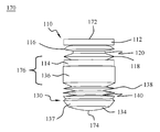
10 is a side view of a stopper member and a tube according to an embodiment of the present invention.
Figure 11 is a top perspective view of the stopper member and tube of Figure 10 in accordance with an aspect of the present invention.
12 is a side view of another stopper according to an embodiment of the present invention.
FIG. 13 is a top perspective view of the stopper member of FIG. 12 according to an embodiment of the present invention;
14 is a side view of another stopper member according to an embodiment of the present invention.
Fig. 15 is a perspective view of the stopper member of Fig. 14 according to an embodiment of the present invention; Fig.
16 is a side view of another stopper member according to an embodiment of the present invention.
17 is a perspective view of the stopper member of Fig. 16 according to an embodiment of the present invention.
18 is a side view of another stopper member according to an embodiment of the present invention.
Fig. 19 is a perspective view of the stopper member of Fig. 18 according to one embodiment of the present invention; Fig.
20 is a perspective view of a pressure transmission device according to an embodiment of the present invention.
21 is a perspective view of another pressure transmission device according to an aspect of the present invention;
22 is a side perspective view of a syringe system in accordance with an aspect of the present invention;
Figure 23 is a top perspective view of the syringe system of Figure 22, in accordance with an aspect of the present invention.
Figure 24 is a side view of the syringe system of Figure 22 with the piston seal system of Figure 1 in a first position, in accordance with an aspect of the present invention.
Figure 25 is a side view of the syringe system of Figure 22 with the piston seal system of Figure 1 in a second position in accordance with an aspect of the present invention.
Figure 26 is a partially exploded side perspective view of a cartridge system having the piston seal system of Figure 1 in a first position, in accordance with an aspect of the present invention;
Figure 27 is a side view of the cartridge system of Figure 26, in accordance with an aspect of the present invention.
Figure 28 is a side view of the cartridge system of Figure 26 with the piston seal system of Figure 1 in a second position, in accordance with an aspect of the present invention.
Figure 29 is a side perspective view of several alternative embodiments of the coupling member of the piston seal system of Figure 1, in accordance with an aspect of the present invention.
일반적으로, 주사기 시스템, 피스톤 시일 시스템 및 스토퍼 시스템이 본원에 개시되어 있다. 또한, 주사기 시스템, 피스톤 시일 시스템 및 스토퍼 시스템을 조립하고 사용하는 방법이 기술된다. In general, a syringe system, a piston seal system, and a stopper system are disclosed herein. Methods of assembling and using a syringe system, a piston seal system, and a stopper system are also described.
이 상세한 설명 및 하기 청구 범위에서, 근위, 원위, 전방, 후방, 내측, 측방, 상위 및 하위라는 단어는 몸체 또는 기준 방향 용어에 대한 장치의 상대적인 배치에 따라 장치의 특정 부분을 나타내는 표준 사용법에 의해 정의된다. 예를 들어, "근위 (proximal)"는 주사 지점에 가장 가까운 장치의 부분을 의미하고, "원위"는 주사 지점으로부터 가장 멀리있는 장치의 부분을 의미한다. 방향 용어에 관해서, "전방"은 장치의 전방 측을 향하는 방향이고, "후방"은 장치의 후방 측을 향하는 방향을 의미하고, "내측(medial)"은 장치의 중심선을 의미하고, "측방"은 장치의 중심선에서 측면으로 또는 중심선에서 멀어지는 방향이고 "상위"는 위의 방향을 의미하고 "하위"는 다른 대상물 또는 구조 아래의 방향을 의미한다.In this description and in the claims that follow, the terms proximal, distal, anterior, posterior, medial, lateral, superior, and subordinate are used by standard usage to refer to a particular portion of the device, Is defined. For example, "proximal " means the portion of the device closest to the injection point and" distal "means the portion of the device that is furthest from the injection point. Refers to the direction toward the front side of the apparatus, "rear" means the direction toward the rear side of the apparatus, "medial" Quot; upper "means the upper direction and" lower "means the direction under the other object or structure from the centerline of the device to the side or away from the centerline.
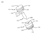
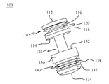
도면에 있어서, 유사 도면부호들은 여러 도면들에 걸쳐 그리고 주사기 피스톤 시일 시스템(100)이 도시되는, 특히 도 1 내지 도 5에서 같은 또는 유사 구성요소들을 지시하는데 사용된다. 피스톤 시일 시스템(100)은 피스톤 시일 부재(110), 커플링 부재(122) 및 피스톤 헤드 부재(130)를 포함할 수 있다. 커플링 부재(122)는 제 1 단부(124) 및 제 2 단부(126)를 포함할 수 있다. 커플링 부재(122)의 제 1 단부(124)는 도 4 및 도 5에 도시된 바와 같이, 피스톤 시일 부재(110)의 제 2 단부(114)에 고정될 수 있다. 커플링 부재(122)의 제 2 단부(126)는 도 4 및 도 5에 도시된 바와 같이 피스톤 헤드 부재(130)의 제 1 단부(132)에 고정될 수 있다. 커플링 부재(122)는 예를 들어, 시일 부재(110) 및 헤드 부재(130)의 직경보다 작은 직경을 가질 수 있다. 커플링 부재(122)는 도 4 및 도 5에 도시된 바와 같이, 시일 부재(110)의 제 2 단부(114) 및 헤드 부재(130)의 제 1 단부(132) 사이의 압력 경감 공간을 생성하도록 작용한다. 커플링 부재(122)는 또한 임의의 누설된 유체를 포획하고 전달되는 약물의 오염을 방지하기 위해 시일 부재(110) 및 헤드 부재(130) 사이의 공간을 생성하도록 작용할 수 있다. In the drawings, like reference numerals are used to indicate like or similar elements throughout the several views and particularly in FIGS. 1-5, in which the syringe
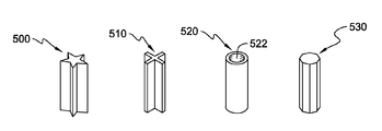
원형 단면을 갖는 단지 하나의 원통형 커플링 부재(122)가 도시되지만, 또한 커플링 부재(122)는 예를 들어, 다각형, 별형, 트러스(truss), 도넛 또는 임의의 다른 형상의 단면을 가질 수 있다. 예를 들어, 도 29에 도시된 바와 같이, 별형을 갖는 커플링 기구(500), "X"형을 갖는 커플링 기구(510), 제 1 단부로부터 제 2 단부로 연장되는 개방부(522)를 포함하는 도넛형 또는 "O"형을 갖는 커플링 기구(520) 및 8각형을 갖는 커플링 기구(530)가 사용될 수 있다. 커플링 부재(122)의 형상은 압력이 제 1 단부(122)에 인가될 때 시일 부재(110)의 임의의 각도 변위 또는 기울기를 방지하기 위하여 시일 부재(110)에 지지력을 제공하도록 선택될 수 있다. Although only one
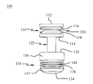
피스톤 시일 시스템(100)은 도 1 내지 도 3에 도시된 바와 같이, 예를 들어, 3개의 부재 구성이거나 또는 대안으로 도 4 및 도 5에 도시된 바와 같이 한 부재 구성일 수 있다. 3개의 부재 구성의 실시예는 제 1 단부(124) 및 제 2 단부(126)를 갖는 커플링 부재(122)를 가질 수 있다. 제 1 단부(124) 및 제 2 단부(126)는 피스톤 헤드 부재(130)의 제 1 단부(132) 및 피스톤 시일 부재(110)의 제 2 단부(114)의 개방부에 있는 대응 나사부들과 정합되도록 나사결합될 수 있다. 대안으로, 또한, 커플링 부재(122)는 예를 들어, 접착제, 초음파 접합, 열적 용융, 가압 끼워맞춤 등에 의해서 피스톤 시일 부재(110) 및 피스톤 헤드 부재(130)에 부착될 수 있다는 것이 고려된다. 피스톤 시일 부재(110)의 한 부재 구성의 실시예는 도 4 및 도 5에 도시된 바와 같이, 몰딩되거나 또는 다르게 형성된 피스톤 시일 시스템(100)일 수 있다. 피스톤 시일 시스템(100)의 부재들의 다른 구성도 역시 도 4 및 도 5에 도시된 바와 같이 피스톤 헤드 부재(130)로부터 이격된 피스톤 시일 부재(110)를 갖는, 피스톤 시일 시스템(100)을 형성하도록 고려된다. The
도 1 내지 도 5에 있어서, 피스톤 시일 부재(110)는 제 1 단부(112)에 있는 제 1 베이스 부분 및 제 2 단부(114)에 있는 제 2 베이스 부분을 포함할 수 있다. 피스톤 시일 부재(110)는 또한 예를 들어, 적어도 하나의 플랜지 부재, 예를 들어 제 1 플랜지 부재(116) 및 제 2 플랜지 부재(118)를 가질 수 있다. 용어 "플랜지 부재", "가요성 부재", "리브" 및 "링"은 본질적으로 동일 구조를 기술할 때 본원에서 상호 교환되게 사용될 수 있다. 플랜지 부재들(116,118)은 원주방향이고 주사기의 벽들과 연속 접촉하고 액체를 포획하는 것을 보장하기 위해 단부들(112,114)과 동일한 원주를 가진다. 플랜지 부재들(116,118) 사이의 공간은 이동 중에 주사기 벽과의 접촉을 최대화하기 위하여 변형될 수 있게 한다. 피스톤 시일 부재(110)는 복수의 플랜지 부재들(116,118)을 포함할 수 있다는 것이 고려된다. 플랜지 부재들(116,118)의 수는 시일에 영향을 미치고 유체가 피스톤 시일 부재(110)를 통과하는 것을 방지하는데 필요한 플랜지 부재들(116,118)의 최소수에서 피스톤 시일 부재(110)가 컨테이너, 챔버, 주사기, 유리병 또는 카트리지 내에서 활주할 수 있게 하는 플랜지 부재들(116,118)의 최대수까지의 범위에 있다. 일 실시예에서, 피스톤 시일 부재(110)는 예를 들어, 대략 0 내지 4개의 플랜지 부재들(116,118)을 포함할 수 있다. 1 to 5, the
또한, 피스톤 시일 부재(110)는 플랜지 부재들(116,118) 사이에 배치된 리세스 또는 홈(120)을 가질 수 있다. 피스톤 시일 부재(110)의 제 2 단부(114)는 커플링 부재(122)를 수용하기 위한 개방부(미도시)를 포함할 수 있다. 제 1 단부(112) 및 제 2 단부(114)는 주사기 컨테이너, 주사기 챔버 또는 패치 펌프 유리병 장치(미도시) 내에 수용되도록 각각 크기설정될 수 있다. 제 1 단부(112) 및 제 2 단부(114)는 피스톤 시일 부재(110)에 의해서 약물을 주사하는데 사용된 가압 매체가 통과하는 것을 방지하고 컨테이너, 챔버 또는 유리병의 근위 단부에 있는 무균 약품을 오염시키는 것을 방지하면서 이동할 수 있도록 크기설정된다. 또한, 적어도 하나의 플랜지 부재들(116,118)은 또한 하기에 상세하게 기술되는 바와 같이, 피스톤 시일 부재(110)에 의해서 가압 매체가 통과하는 것을 방지하고 무균 약물을 오염시키는 것을 방지하게 보조하기 위하여 컨테이너, 챔버 또는 유리병의 측벽과 결합하도록 크기설정될 수 있다. 피스톤 시일 부재(110)는 시스템(100)에 대한 압력 경감 영역을 제공한다. In addition, the
도 1 내지 도 5에 도시된 바와 같이, 피스톤 헤드 부재(130)는 제 1 단부(132)에 있는 제 1 베이스 부분(136) 및 제 2 단부(134)에 있는 제 2 베이스 부분(137)을 포함할 수 있다. 제 1 베이스 부분(136)은 예를 들어 제 2 베이스 부분(137)보다 두꺼울 수 있다. 피스톤 헤드 부재(130)는 또한 제 1 단부(132)에 있는 제 1 베이스 부분(136) 및 제 2 단부(134)에 있는 제 2 베이스 부분(137) 사이에 배치된 적어도 하나의 리세스 또는 홈(140)과 적어도 하나의 플랜지 부재(138)를 포함할 수 있다. 제 1 베이스 부분(136) 및 제 2 베이스 부분(137)은 컨테이너, 챔버, 주사기, 유리병 또는 카트리지의 근위 단부에 있는 유체 경로를 통해서 주사 중에 약물이 컨테이너, 챔버 또는 유리병의 원위 단부로 통과하는 것을 방지하기 위해 주사기 컨테이너, 주사기 챔버 또는 패치 펌프 유리병 장치(미도시) 내에 수용되도록 크기설정될 수 있다. 피스톤 헤드 부재(130)는 약물이 컨테이너, 챔버, 주사기, 유리병 또는 카트리지의 원위 단부로 통과하는 것을 방지함으로써 약물의 무균 상태를 유지한다. 적어도 하나의 플랜지 부재(138)는 또한 컨테이너, 챔버 또는 유리병의 측벽과 결합하고 적당한 복용량의 약물이 환자에게 전달되는 것을 보장하기 위하여 약물이 피스톤 헤드 부재(130)에 의해서 컨테이너, 챔버 또는 유리병의 원위 단부를 향하여 통과하는 것을 방지하게 보조하도록 크기설정될 수 있다. 적어도 하나의 플랜지 부재(138)와 제 1 및 제 2 베이스 부분(136,137) 사이의 원주 및 공간은 적어도 하나의 플랜지 부재(138) 및 컨테이너, 챔버 또는 유리병의 측벽 사이의 최대 접촉을 허용한다. 피스톤 헤드 부재(130)는 복수의 플랜지 부재들(138)을 포함할 수 있다는 것이 고려된다. 플랜지 부재들(118)의 수는 예를 들어, 시일에 영향을 미치고 유체가 피스톤 헤드 부재(130)를 통과하는 것을 방지하는데 필요한 플랜지 부재들(138)의 최소수에서 피스톤 헤드 부재(130)가 컨테이너, 챔버, 주사기, 유리병 또는 카트리지 내에서 활주할 수 있게 하는 플랜지 부재들(138)의 최대수까지의 범위에 있다. 일 실시예에서, 피스톤 헤드 부재(130)는 예를 들어, 대략 2 내지 5개의 플랜지 부재들(138)을 포함할 수 있다. 1 to 5, the
이제, 도 6 및 도 7에는, 다른 피스톤 시일 시스템(150)이 도시된다. 피스톤 시일 시스템(150)은 두 부재 시스템이다. 피스톤 시일 시스템(150)은 피스톤 시일 부재(110) 및 피스톤 헤드 부재(130)를 포함할 수 있다. 피스톤 시일 부재(110) 및 피스톤 헤드 부재(130)는 도 1 내지 도 5를 참조하여 상술한 것과 동일할 수 있으며 간략하게 하기 위해 여기서 다시 설명하지 않는다. 시일 부재(110) 및 헤드 부재(130)는 시일 부재(110) 및 헤드 부재(130) 사이에 압력 경감 공간을 남겨 두도록 이격된 컨테이너, 챔버 또는 유리병에 배치될 수 있다. 주사 중에 힘이 시일 부재(110)에 인가될 수 있고 상기 시일 부재는 헤드 부재(130)에 힘을 교대로 인가하여 헤드 부재(130)를 병진이동시키고 약물을 환자에게 전달한다. 시일 부재(110)에 인가된 힘은 시일 부재(110)의 제 2 단부(114)가 헤드 부재(130)의 제 1 단부(132)와 직접 접촉하게 유도하여 헤드 부재(130)를 이동시킨다. 시일 부재(110)의 제 2 단부(114) 및 헤드 부재(130)의 제 1 단부(132)는 예를 들어 제 2 단부(114)가 제 1 단부(132)와 완전히 접촉하게 허용하는 정합 크기 및 구성을 가질 수 있다. 6 and 7, another
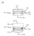
다른 피스톤 시일 시스템(170)은 도 8 및 도 9에 도시된다. 피스톤 시일 시스템(170)은 한 부재 시스템이다. 피스톤 시일 시스템(170)은 플랜지들(138)을 포함하는 피스톤 헤드 부재(130)에 직접 부착된 플랜지들(116,118)을 포함하는 피스톤 시일 부재(110)를 포함할 수 있다. 시일 부재(110) 및 헤드 부재(130)는 도 1 내지 도 5를 참조하여 상술한 것과 동일하고 간략하게 하기 위해 여기서 다시 설명하지 않는다. 그러나, 시일 부재(110)의 제 2 단부(114)에 있는 베이스 부분 및 헤드 부재(130)의 베이스 부분(136)은 예를 들어, 함께 고정되거나 또는 단일 부재로서 형성되어서 중간 부분(176)을 생성할 수 있다. 중간 부분(176)은 시일 부재(110) 및 헤드 부재(130) 사이에서 배리어로서 작용할 수 있다. 피스톤 시일 시스템(170)은 예를 들어 몰딩되거나 또는 단일 부재로서 형성될 수 있다. 피스톤 시일 시스템(170)은 시일 부재(110) 및 헤드 부재(130)가 함께 이동하게 허용하여 컨테이너, 챔버 또는 유리병으로부터의 주사 및 충전이 모두 가능하게 하기 때문에 재사용가능한 컨테이너, 챔버 또는 유리병에서 사용될 수 있다. Another
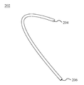
도 10 및 도 11은 스토퍼 시스템(200)의 일 실시예를 도시한다. 스토퍼 시스템(200)은 압력 전달 장치(202) 및 스토퍼 부재(210)를 포함할 수 있다. 스토퍼 시스템(200)은 컨테이너, 챔버 또는 유리병의 원위 단부로의 가압 매체의 전달을 허용하기 위하여 하기에 더욱 상세하게 기술된 바와 같이 컨테이너, 챔버 또는 유리병의 단부에 고정될 수 있다. 압력 전달 장치(202)는 제 1 단부(204) 및 제 2 단부(206)를 포함할 수 있다. 제 1 단부(204)는 환자에 대한 약물의 전달을 실행하기 위하여 컨테이너, 챔버 또는 유리병 안으로의 유체의 주사를 위해 압력 전달 시스템에 결합될 수 있다. 유체는 예를 들어, 액체, 가스, 공기 등일 수 있다. 제 2 단부(206)는 제 2 단부(212)에 있는 스토퍼 부재(210)에 결합될 수 있다. 스토퍼 부재(210)는 제 1 단부(212) 및 제 1 단부(212)의 반대편인 제 2 단부(214)를 포함할 수 있다. 스토퍼 부재(210)는 또한 제 1 단부(212) 및 제 2 단부(214) 사이에서 연장되는 측벽(216)을 포함할 수 있다. 측벽(216)은 직선형, 테이퍼형, 아치형 또는 컨테이너, 챔버 또는 유리병에 있는 개방부 내에 고정되게 성형될 수 있다. 스토퍼 부재(210)는 또한 도 11에 도시된 바와 같이, 개방부(218)를 포함할 수 있다. 개방부(218)는 압력 전달 장치(202)를 수용하고 가압 유체의 통과를 허용하기 위하여 제 1 단부(212)에서 제 2 단부(214)로 연장될 수 있다. 10 and 11 illustrate one embodiment of the
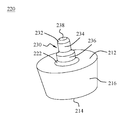
스토퍼 부재(220)의 다른 실시예는 도 12 및 도 13에 도시된다. 스토퍼 부재(220)는 제 1 단부(212), 제 1 단부(212)의 반대편인 제 2 단부(214), 제 1 단부(212) 및 제 2 단부(214) 사이에서 연장되는 측벽(216)을 포함할 수 있다. 피팅 부재(230)는 커플링 부분(222)에 있는 스토퍼 부재(220)의 제 1 단부(212)에 고정될 수 있다. 피팅 부재(230)는 제 1 단부(232), 수용 부분(234) 및 베이스 부분(236)을 포함할 수 있다. 수용 부분(234)은 도 20 및 도 21에 대해서 하기에 더욱 상세하게 기술된 바와 같이, 장치(190,202)와 같은 압력 전달 장치에 고정되도록 크기설정될 수 있다. 베이스 부분(236)은 피팅 부재(230)를 제 1 단부(212)에 고정하기 위해 커플링 부분(222)에 고정될 수 있다. 베이스 부분(236)은 예를 들어 수용 부분(234)보다 큰 직경을 가질 수 있다. 스토퍼 부재(220)는 또한 도 13에 도시된 바와 같이, 피팅 부재(230)의 제 1 단부(232)로부터 스토퍼 부재(220)의 제 2 단부(214)로 연장되는 개방부(238)를 포함할 수 있다. 개방부(238)는 가압 매체가 스토퍼 부재(220)를 통과해서 그리고 컨테이너, 챔버 또는 유리병(미도시) 안으로 들어갈 수 있게 한다. Another embodiment of the
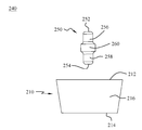
이제 도 14 및 도 15에 있어서, 스토퍼 시스템(240)의 또다른 실시예가 도시된다. 스토퍼 시스템(240)은 스토퍼 부재(210) 및 피팅 부재(250)를 포함하는 두 부재이다. 스토퍼 부재(210)는 도 10 및 도 11을 참조하여 상술한 유형이고, 이에 대해서는 단순성을 위하여 다시 기술하지 않는다. 피팅 부재(250)는 제 1 단부(252) 및 상기 제 1 단부(252)의 반대편에 있는 제 2 단부(254)를 포함할 수 있다. 피팅 부재(250)는 제 1 수용 부분(256), 제 2 수용 부분(258)과 제 1 수용 부분(256) 및 제 2 수용 부분(258) 사이에 배치된 중간 부분(260)을 포함할 수 있다. 중간 부분(260)은 예를 들어, 제 1 수용 부분(256) 및 제 2 수용 부분(258)보다 큰 직경을 가질 수 있고 제 1 수용 부분(256) 및 제 2 수용 부분(258)은 예를 들어, 동일 직경을 가질 수 있다. 제 1 수용 부분(256)은 도 20 및 도 21을 참조하여 하기 기술된 바와 같이 장치(190,202)와 같은 압력 전달 장치에 고정되게 크기설정될 수 있다. 제 2 수용 부분(258)은 스토퍼 부재(210)에 있는 개방부(218) 안으로 삽입되어 고정되도록 크기설정될 수 있다. 14 and 15, another embodiment of the
도 16 및 도 17은 다른 스토퍼 부재(280)를 도시한다. 스토퍼 부재(280)는 제 1 단부(282)에 있는 제 1 베이스 부분, 제 2 단부(284)에 있는 제 2 베이스 부분 및 상기 스토퍼 부재(280)의 외면 상의 제 1 및 제 2 베이스 부분들 사이에서 연장되는 복수의 나사부들(286)을 포함할 수 있다. 복수의 나사부들(286)은 약물을 투여하기 위하여 스토퍼 부재(280)를 컨테이너, 챔버 또는 유리병에 고정하도록 컨테이너, 챔버 또는 유리병의 원위 단부에 있는 복수의 나사부들(미도시)에 대응할 수 있다. 스토퍼 부재(280)는 또한 스토퍼 부재(280)의 예를 들어, 일반적인 중심점에서 제 1 단부(282)에서 제 2 단부(284)로 연장되는 개방부(288)를 포함할 수 있다. 개방부(288)는 도 20 및 도 21을 참조하여 하기에 더욱 상세하게 기술된 바와 같이 장치(190,202)와 같은 압력 전달 장치를 수용하도록 크기설정될 수 있다. Figs. 16 and 17 show
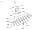
다른 스토퍼 시스템(290)은 도 18 및 도 19에 도시된다. 스토퍼 시스템(290)은 스토퍼 부재(280) 및 피팅 부재(250)를 포함할 수 있다. 스토퍼 부재(280)은 도 16 및 도 17을 참조하여 상술한 유형일 수 있고 피팅 부재(250)는 도 14 및 도 15를 참조하여 상술한 유형일 수 있다. 스토퍼 부재(280) 및 피팅 부재(250)는 간략성을 위하여 여기서 다시 설명하지 않는다. 피팅 부재(250)의 제 1 수용 부분(256)은 도 20 및 도 21을 참조하여 하기에 더욱 상세하게 기술된 바와 같이 장치(190,202)와 같은 압력 전달 장치에 고정되도록 크기설정될 수 있다. 피팅 부재(250)의 제 2 수용 부분(258)은 스토퍼 부재(280)에 있는 개방부(288) 안으로 삽입되어서 고정되도록 크기설정될 수 있다. 피팅 부재(250)는 예를 들어, 제 2 수용 부분(258)의 외면 상에 배치된 복수의 나사부들(미도시)을 포함할 수 있다. 제 2 수용 부분(258) 상의 복수의 나사부들은 피팅 부재(250)를 스토퍼 부재(280)에 고정하기 위한 개방부(288)의 내면 상의 복수의 나사부들(미도시)에 대응할 수 있다. 대안 고정 수단, 예를 들어, 접착제, 단일 부재 몰딩, 가압 끼워맞춤 등도 역시 피팅 부재(250)를 스토퍼 부재(280)에 고정하도록 고려된다.
도 20은 압력 전달 장치(202)를 도시한다. 도 10 및 도 11을 참조하여 상술한 바와 같이, 압력 전달 장치(202)는 제 1 단부(204) 및 제 2 단부(206)를 포함할 수 있다. 압력 전달 장치(202)는 제 1 단부(204)로부터 제 2 단부(206)로 압력 매체가 통과하게 허용하도록, 예를 들어, 튜브 또는 다른 중공 세장형 구조체일 수 있다. 제 1 단부(204)는 약물을 환자에게 전달하기 위해 가압 유체를 주사기 컨테이너, 챔버 또는 유리병(미도시)에 전달하기 위해 압력 전달 시스템(미도시)에 결합되도록 크기설정될 수 있다. 제 2 단부(206)는 직접 또는 개별 또는 일체형 피팅 부재(230, 250)를 사용하여 스토퍼 부재(210, 220, 240, 280, 290)에 고정되도록 크기설정될 수 있다. Fig. 20 shows a
이제 도 21에 있어서, 대안 압력 전달 장치(190)가 도시된다. 압력 전달 장치(190)는 제 1 단부(204), 제 2 단부(206) 및 스테킹 바늘(208)을 포함할 수 있다. 압력 전달 장치(190)는 예를 들어, 유체가 제 1 단부(204)로부터 제 2 단부(206)로 통과하고 스테킹 바늘(208)을 통해서 주사기 컨테이너, 챔버 또는 유리병(미도시)으로 이동하게 허용하는 튜브 또는 다른 중공 구조체일 수 있다. 스테킹 바늘(208)은 제 2 단부(206)에 고정될 수 있다. 스테킹 바늘(208)은 예를 들어, 개방부(210,288)를 포함하기 위해 스토퍼 부재에 대한 필요성없이 스토퍼 부재(210,280) 안으로 직접 삽입될 수 있다. 대안 압력 전달 장치(202, 190)는 또한 약물을 환자에게 전달하기 위하여 시스템(100, 150 또는 170)과 같은 피스톤 시일 시스템을 이동시키기 위하여 압력 전달 시스템으로부터 주사기 컨테이너, 챔버 또는 유리병으로 가압 매체를 전달하기 위한 것으로 고려된다. Referring now to Fig. 21, an
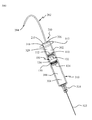
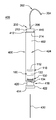
이제 도 22 내지 도 25에 있어서, 주사 시스템(300)의 제 1 실시예가 도시된다. 주사 시스템(300)은 컨테이너(310), 유체 경로(322), 스토퍼 시스템(200) 및 주사기 피스톤 시일 시스템(100)을 포함할 수 있다. 컨테이너(310)는 스토퍼 시스템(200)을 수용하기 위한 제 1 단부 및 유체 경로(322)를 수용하기 위한 제 2 단부를 포함할 수 있다. 주사기 피스톤 시일 시스템(100)은 컨테이너(310)에 있는 개방부(316) 안으로 설치하도록 크기설정될 수 있다. 피스톤 시일 시스템(100)의 외면은 컨테이너(310)의 내면 또는 벽들과 결합하도록 크기설정된다. 컨테이너(310)는 예를 들어, 약물 또는 유체를 환자에게 투여하는데 사용된 주사기, 유리병 또는 다른 컨테이너일 수 있다. 컨테이너(310)는 예를 들어, 약물 또는 유체를 저장하고 환자에게 전달하기 위해 적합한 플라스틱, 유리, 금속 또는 임의의 다른 재료로 제조될 수 있다. Referring now to Figures 22-25, a first embodiment of a
도 22 내지 도 25의 도시된 실시예에서, 컨테이너(310)의 제 1 단부는 예를 들어, 개방부(316)를 둘러싸는 플랜지(312)를 포함할 수 있다. 컨테이너(310)의 제 2 단부는 유체 경로(322)를 수용하기 위한 부착 부분(314)을 포함할 수 있다. 유체 경로(322)는 약물을 환자에게 전달하기 위한 바늘, 캐뉼러 또는 다른 장치일 수 있다. 컨테이너(310)는 개방부(316)로부터 부착 부분(314)으로 연장되는 캐비티 또는 챔버(318,320)를 포함할 수 있다. 부착 부분(314)은 챔버(318,320)를 유체 경로(322)에 결합하여 유체가 챔버(318,320)로부터 유체 경로(322)로 통과하게 허용한다. 컨테이너(310)는 예를 들어, 약물 또는 유체를 저장하고 환자에게 전달하기 위해 바람직할 수 있는 임의의 형상을 가지며 주사기 피스톤 시일 시스템(100)은 컨테이너(310) 내의 개방부(316)의 형상에 대응하는 형상을 가질 수 있다. 22-25, the first end of the
주사 시스템(300)은 유체 경로(322)를 컨테이너(310) 안으로 삽입함으로써 조립될 수 있다. 비록, 도시되지 않았지만, 약물이 투여되기 전에 유체 경로(322)로부터 약물이 방출되지 않는 것을 보장하도록 유체 경로(322)가 덮개가 덮혀지는 것이 바람직하다. 또한, 유체 경로(322)에 우연히 고착되는 것을 방지하도록 유체 경로(322)를 덮개로 덮는 것이 바람직하다. 다음, 챔버(318,320)는 공지된 충전 방법에 의해서 원하는 양의 약물(304)로 충전될 수 있다. 일단 원하는 양의 약물(304)이 챔버(318,320) 내에 수용되면, 주사기 피스톤 시일 시스템(100)은 개방부(316) 안으로 삽입될 수 있다. 주사기 피스톤 시일 시스템(100)이 컨테이너(310) 안으로 삽입될 때, 챔버(318,320)는 컨테이너(310)의 제 2 단부에 있는 제 1 챔버(318) 및 컨테이너(310)의 제 1 단부에 있는 제 2 챔버(320)로 분할된다. 대안으로, 챔버(318)는 피스톤 시일 시스템(100)이 컨테이너(310)에 있는 개방부(316) 안으로 삽입된 후에 원하는 양의 약물(304)로 공지된 방법에 의해서 충전될 수 있다. 주사기 피스톤 시일 시스템(100)은 가압 유체(302)와 약물(304) 사이의 분리를 유지하면서 컨테이너(310) 내의 시스템(100)의 활주 이동을 허용하는 예를 들어, 임의의 재료로 제조될 수 있다. 주사기 피스톤 시일 시스템(100)의 재료는 주사될 약물(304) 및 무균 약물(304)의 오염이 발생하지 않는 것을 보장하는데 사용되는 가압 유체(302)에 기초하여 선택될 수 있다. 비록, 주사기 피스톤 시일 시스템(100)이 도시되지만, 주사기 피스톤 시일 시스템(150, 170) 및 다른 조합물도 역시 사용될 수 있다. The
일단, 약물(304) 및 주사기 피스톤 시일 시스템(100)이 컨테이너(310) 내에 있으면, 그때 스토퍼 시스템(200)은 컨테이너(310)의 원위 단부에 고정될 수 있다. 스토퍼 시스템(200)은 예를 들어, 스토퍼 시스템(200)의 제 2 단부(214)가 피스톤 시일 부재(110)의 제 1 단부(112)와 직접 접촉하도록, 컨테이너(310) 안으로 삽입될 수 있다. 스토퍼 시스템(200)은 챔버(320)를 폐쇄하기 위하여 스토퍼 부재(210)를 개방부(316) 안으로 삽입함으로써 고정될 수 있다. 비록, 스토퍼 시스템(200)이 도시되지만, 예를 들어, 스토퍼 부재(220,280) 및 그 조합물을 포함하는 다른 스토퍼 시스템도 역시 사용될 수 있다. 스토퍼 시스템(200)은 또한 제 1 단부(204)에서 압력 전달 시스템과 결합하고 제 2 단부(206)에서 스토퍼 부재(210)와 결합될 수 있는 압력 전달 장치(202)를 포함할 수 있다. Once the
주사 시스템(300)이 조립된 후에, 시스템(300)은 주사를 위해 사용될 수 있다. 주사 시스템(300)은 압력 전달 장치(202)를 통해서 그리고 챔버(320) 안으로 가압 매체(302)의 유동을 개시하기 위하여 연결된 압력 전달 장치에서 선회함으로써 주사를 위하여 사용될 수 있다. 압력 매체(302)는 컨테이너(310)의 원위 단부에서 챔버(320)를 충전할 때, 가압 매체(302)에 의해서 피스톤 시일 부재(110)의 제 1 단부(112)에 힘이 인가된다. 일 실시예에서, 주사 시스템(300)은 예를 들어, 가압 매체(302)가 액체이면 컨테이너(310)로부터 공기 또는 가스의 방출을 허용하도록 적어도 하나의 배기구를 포함할 수 있다. 피스톤 시일 부재(110) 및 피스톤 헤드 부재(130)는 가압 매체(302)가 약물(304) 안으로 누설되는 것을 방지하도록 각각 크기설정되므로, 가압 매체(302)를 약물(304)로부터 격리시키는 배리어를 제공한다. 그러나, 유체(302, 304)가 누설되면, 커플링 부재(122) 주위에 형성된 공간은 유체(302, 304)가 이탈하여 약물(304)을 오염시키지 않도록 포획한다. 시일 부재(110)의 홈(120) 및 플랜지 부재(116, 118)와 헤드 부재(130)의 리세스(140) 및 플랜지 부재(138)는 또한 누설될 수 있는 임의의 유체(302, 304)를 포획하고 누설된 가압 유체(302)가 약물(304)을 오염시키는 것을 방지하는 것을 보조하도록 작용할 수 있다.After the
일단, 피스톤 시일 부재(110)에 인가된 힘이 대응하는 피스톤 시일 시스템(100) 상의 본질적인 마찰 벽의 힘들을 극복할 만큼 충분한 결과적 힘을 발생시키기에 충분하다면, 피스톤 시일 시스템(100)은 컨테이너(310)의 근위 단부에 있는 부착 부분(314)을 향하여 이동을 개시한다. 피스톤 시일 시스템(100)이 이동할 때, 유체 경로(322)에서의 유체 저항은 극복되고 약물(304)은 환자에게 전달되기 위해 유체 경로(322) 밖으로 압송된다. 이제 도 24 및 도 25를 참조할 때, 도 24는 가압 매체(302)가 챔버(318) 안으로 펌핑되도록 개시될 때의 피스톤 시일 시스템(100)의 위치를 도시한다. 도 25는 모든 약물(304)이 환자에게 전달된 후의 피스톤 시일 시스템(100)의 위치를 도시한다. Once the force applied to the
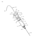
이제 도 26 내지 도 28에 있어서, 주사 시스템(400)의 일 실시예가 도시된다. 주사 시스템(400)은 컨테이너(410), 유체 경로(430), 스토퍼 시스템(200) 및 피스톤 시일 시스템(100)을 포함할 수 있다. 컨테이너(410)는 스토퍼 시스템(200)을 수용하기 위한 제 1 단부 및 유체 경로(430)를 수용하기 위한 제 2 단부를 포함할 수 있다. 피스톤 시일 시스템(100)은 컨테이너(410) 내의 개방부(416) 안으로 끼워지도록 크기설정될 수 있다. 피스톤 시일 시스템(100)의 외면은 컨테이너(410)의 내면 또는 벽들에 결합하도록 크기설정된다. 컨테이너(410)는 예를 들어, 약물 또는 유체를 환자에게 투여하기 위해 사용된 카트리지, 유리병, 주사기 또는 다른 컨테이너일 수 있다. 컨테이너(410)는 예를 들어, 플라스틱, 유리, 금속 또는 약물 또는 유체를 환자에게 저장 및 전달하는데 적당한 임의의 다른 재료로 제조될 수 있다. 26-28, one embodiment of a
도 26 내지 도 28의 도시된 실시예에 있어서, 컨테이너(410)는 예를 들어, 제 1 단부(412) 및 제 2 단부(414)를 포함할 수 있다. 제 2 단부(414)는 유체 경로(430)를 수용하기 위한 부착 부분(418)을 포함할 수 있다. 부착 부분(418)은 예를 들어, 네크 부분(420) 및 플랜지 부분(422)을 포함할 수 있다. 네크 부분(420)은 예를 들어, 컨테이너(410) 및 플랜지 부분(422)보다 작은 직경을 가질 수 있다. 유체 경로(430)는 예를 들어, 바늘, 캐뉼러 또는 약물을 환자에게 전달하기 위한 다른 장치일 수 있다. 컨테이너(410)는 개방부(416)로부터 부착 부분(418)으로 연장되는 챔버 또는 캐비티(424)를 포함한다. 부착 부분(418)은 챔버(424)를 유체 경로(430)에 결합하여 유체가 챔버(424)로부터 유체 경로(430)로 통과할 수 있게 한다. 컨테이너(410)는 예를 들어 약물 또는 유체를 저장하고 환자에게 전달하기 위해 바람직한 임의의 형상을 가지며 피스톤 시일 시스템(100)은 컨테이너(410) 내의 개방부(416)의 형상에 대응하는 형상을 가질 수 있다. 26-28, the
주사 시스템(400)은 유체 경로(430)를 컨테이너(410) 안으로 삽입함으로써 조립될 수 있다. 비록 도시되지 않았지만, 유체 경로(430)는 약물이 투여되기 전에 유체 경로(430)로부터 방출되지 않도록 보장하고 유체 경로(430)와의 우연한 접촉을 방지하도록 덮개로 덮혀지는 것이 바람직하다. 다음, 챔버(424)는 공지된 충전 방법에 의해서 원하는 양의 약물로 충전될 수 있다. 일단, 원하는 양의 약물이 챔버(424) 안으로 수송되면, 피스톤 시일 시스템(100)은 개방부(416) 안으로 삽입될 수 있다. 피스톤 시일 시스템(100)이 컨테이너(410)의 챔버(424) 안으로 삽입될 때, 도 26에 도시된 바와 같이, 컨테이너(410)의 제 1 단부에 배치된다. 대안으로, 챔버(424)는 피스톤 시일 시스템(100)이 컨테이너(410) 내의 개방부(416) 안으로 삽입된 후에 원하는 양의 약물로 공지된 방법에 의해서 충전될 수 있다. 피스톤 시일 시스템(100)은 예를 들어, 압력 전달 장치(202)에 의해서 컨테이너(410) 안으로 주사되는 압력 유체 및 약물 사이의 분리를 유지하면서 컨테이너(410) 내에서 시스템(100)의 활주 이동을 허용하는 임의의 재료로 제조될 수 있다. 피스톤 시일 시스템(100)의 재료는 무균 약물의 오염이 발생하지 않는 것을 보장하는데 사용된 가압 유체 및 분사되는 약물에 기초하여 선택될 수 있다. 비록, 피스톤 시일 시스템(100)이 도시되지만, 피스톤 시일 시스템(150,170) 및 다른 조합물도 역시 사용될 수 있다. The
일단, 약물 및 피스톤 시일 시스템(100)이 컨테이너(410) 내에 있다면, 그 다음 스토퍼 시스템(200)은 컨테이너(410)의 원위 단부에 고정될 수 있다. 스토퍼 시스템(200)은 스토퍼 시스템(200)의 제 2 단부(214)이 도 26에 도시된 바와 같이, 피스톤 시일 부재(110)의 제 1 단부(112)와 직접 접촉하도록, 예를 들어, 컨테이너(410) 안으로 삽입될 수 있다. 스토퍼 시스템(200)은 챔버(424)를 폐쇄하기 위하여 스토퍼 부재(210)를 개방부(416) 안으로 삽입함으로써 고정될 수 있다. 비록, 스토퍼 시스템(200)이 도시되지만, 예를 들어, 스토퍼 부재(220,280) 및 그 조합물을 포함하는 다른 스토퍼 시스템들도 역시 사용될 수 있다. 스토퍼 시스템(200)은 또한 제 1 단부(204)에서 압력 전달 시스템에 결합되고 제 2 단부(206)에서 스토퍼 부재(210)에 결합되는 압력 전달 장치(202)를 포함할 수 있다. Once the drug and
주사 시스템(400)이 조립된 후에, 시스템(400)은 주사를 위해서 사용될 수 있다. 주사 시스템(400)은 압력 전달 장치(202)를 통해서 그리고 챔버(424) 안으로 가압 매체(402)의 유동을 개시하기 위하여 연결된 압력 전달 장치에서 선회시킴으로써 주사를 위하여 사용될 수 있다. 가압 매체(402)가 컨테이너(410)의 원위 단부에 있는 챔버(424)를 충전할 때, 가압 매체(402)에 의해서 피스톤 시일 부재(110)의 제 1 단부(112)에 힘이 인가된다. 일 실시예에 있어서, 주사 시스템(400)은 예를 들어, 가압 매체(402)가 액체이면, 컨테이너(410)로부터 공기 또는 가스의 방출을 허용하는 적어도 한의 일방향 배기구를 포함할 수 있다. 피스톤 시일 부재(110) 및 피스톤 헤드 부재(130)는 가압 매체(402)가 약물(404) 안으로 누설되는 것을 방지하도록 크기설정되므로, 가압 매체(402)를 약물(404)로부터 격리시키는 배리어를 제공한다. 그러나, 유체(402,404)가 누설되면, 커플링 부재(122) 주위에 생성된 공간은 유체(402,404)가 이탈하여 약물(404)을 오염시키지 않게 포획한다. 시일 부재(110)의 홈(120) 및 플랜지 부재(116,118) 및 헤드 부재(130)의 리세스(140) 및 플랜지 부재(138)는 또한 누설될 수 있는 임의의 유체(402,404)를 포획하는 것을 보조하고 누설된 가압 유체(402)가 약물(404)을 오염시키는 것을 방지하도록 작용할 수 있다. After the
일단, 피스톤 시일 부재(110)에 인가된 힘이 대응하는 피스톤 시일 시스템(100) 상의 본질적인 마찰 벽 힘을 극복할 만큼 큰 결과적 힘을 발생시키기에 충분하면, 피스톤 시일 시스템(100)은 도 27에 도시된 바와 같이, 컨테이너(410)의 제 2 또는 근위 단부(414)를 향하여 이동을 개시한다. 피스톤 시일 시스템(100)이 이동할 때, 유체 경로(430)에서의 유체 저항은 극복되고 약물(404)은 환자에게 전달되기 위해 유체 경로(430)로부터 밖으로 압송된다. 모든 약물(404)이 환자에게 전달된 후에 피스톤 시일 시스템(100)의 위치는 도 28에 도시된다. Once the force applied to the
본원의 교시에 기초하여 당업자가 인식할 수 있는 바와 같이, 본 발명의 범주 내에서 본 발명의 상술한 다른 실시예에 많은 변화 및 변형이 이루어질 수 있다. 예를 들어, 주사 시스템들은 본원에 기술되고 도시된 실시예들보다 더욱 많은 또는 더욱 적은 구성요소들 또는 특징들을 포함할 수 있다. 예를 들어, 도 1 내지 도 5 및 도 6 내지 도 7 및 도 8 내지 도 9의 구성요소들 및 특징들은 모두 당업자들중 하나에 의해서 변형 또는 변경되는 대안 조합들에서 상호 교환식으로 사용될 수 있다. 또한, 도 10 내지 도 11, 도 12 내지 도 13, 도 14 내지 도 15, 도 16 내지 도 17 및 도 18 내지 도 19의 구성요소들 및 특징들은 모두 당업자들중 하나에 의해서 변형 또는 변경되는 대안 조합들에서 상호 교환식으로 사용될 수 있다. 따라서, 현재 양호한 실시예들의 상세한 설명은 본 발명의 제한하는 것과는 반대로 이해적으로 간주되어야 한다. As will be appreciated by those skilled in the art based on the teachings herein, many variations and modifications may be made to the above described other embodiments of the invention within the scope of the invention. For example, the scanning systems may include more or fewer components or features than the embodiments described and illustrated herein. For example, the elements and features of FIGS. 1-5 and 6-7 and 8-9 may all be used interchangeably in alternative combinations that are modified or altered by one of ordinary skill in the art. It should also be noted that the components and features of FIGS. 10-11, 12-13, 14-15, 16-17, and 18-19, all of which are modified or altered by one of ordinary skill in the art, Can be used interchangeably in combinations. Accordingly, the detailed description of the presently preferred embodiments is to be considered as contemplated contrary to the limitations of the present invention.
본원에 사용된 용어는 단지 특정 실시예들을 설명하기 위한 목적이고 본 발명을 제한하려는 의도가 아니다. 본원에서 사용된 바와 같이, 단수 용어들은 문맥에서 명확하게 다르게 표시하지 않으면 복수의 형태들도 포함하도록 의도된 것이다. 용어 "구비하다"(및 "구비하는" 등과 같은 임의의 형태의 구비하다), "가지다"("가지는" 등과 같은 임의의 형태의 가지다), "포함하다"(및 "포함하는" 등과 같은 임의의 형태의 포함하다), 그리고 "수용하다"(및 "수용하는" 등과 같은 임의의 형태의 수용하다)는 개방형 연결동사라는 것을 추가로 이해할 수 있다. 결과적으로, 하나 이상의 단계들 또는 요소들을 "구비하는", "가지는", "포함하는" 또는 "수용하는" 방법 또는 장치는 이들 하나 이상의 단계들 또는 요소들을 소유하지만, 이들 하나 이상의 단계들 또는 요소들을 단지 소유하는 것으로 국한되지 않는다. 마찬가지로, 하나 이상의 특징들을 "구비하는", "가지는", "포함하는" 또는 "수용하는" 방법의 단계 또는 장치의 요소는 이들 하나 이상의 특징들을 소유하지만, 이들 하나 이상의 특징들을 단지 소유하는 것으로 국한되지 않는다. 더우기, 임의의 방식으로 구성되는 장치 또는 구조체는 적어도 그 방식으로 구성되지만, 또한 목록에 없는 방식으로도 구성될 수 있다. The terminology used herein is for the purpose of describing particular embodiments only and is not intended to be limiting of the invention. As used herein, the singular terms are intended to include plural forms unless the context clearly dictates otherwise. (Including any form such as "having", "having", etc.), "having" (having any form such as "having"), ), And "accept" (and any form of acceptance, such as "accepting") is an open connect verb. Consequently, any method or apparatus that "comprises", "comprises", "comprises", or "accommodates" one or more steps or elements possesses one or more of these steps or elements, But is not limited to just possessing. Likewise, elements of a step or apparatus of a method "comprising," "having," "comprising," or "accommodating" one or more features are intended to encompass these one or more features, It does not. Furthermore, devices or structures constructed in any manner are configured in at least that way, but may also be configured in a manner not listed.
본 발명은 양호한 실시예들을 참조하여 기술되었다. 여기에 기술된 구조적 및 동작적 실시예는 동일한 일반적인 특징, 특성 및 일반적인 시스템 동작을 제공하기 위한 복수의 가능한 구성의 예시임을 이해할 것이다. 앞서 설명한 상세한 설명을 읽고 이해하면 다르게 수정 및 변경이 이루어질 수 있다. 본 발명은 이러한 모든 변형 및 변경을 포함하는 것으로 해석되어야 한다. The invention has been described with reference to preferred embodiments. It will be appreciated that the structural and operational embodiments described herein are illustrative of a plurality of possible configurations for providing the same general features, characteristics, and general system operation. Modifications and alterations may occur to others upon the reading and understanding of the foregoing detailed description. The present invention should be construed as including all such variations and modifications.
Claims (20)
피스톤 시일 부재; 및
상기 피스톤 시일 부재와 정렬된 피스톤 헤드 부재를 포함하는, 피스톤 시일 시스템.In a piston seal system,
A piston seal member; And
And a piston head member aligned with the piston seal member.
제 1 단부 및 제 2 단부를 갖는 커플링 부재를 추가로 포함하고, 상기 제 1 단부는 상기 피스톤 시일 부재와 접촉하고 상기 제 2 단부는 상기 피스톤 헤드 부재와 접촉하여, 상기 피스톤 시일 부재 및 상기 피스톤 헤드 부재 사이에 공간을 형성하는, 피스톤 시일 시스템.The method according to claim 1,
Wherein the first end portion is in contact with the piston seal member and the second end portion is in contact with the piston head member such that the piston seal member and the piston < RTI ID = 0.0 > Thereby forming a space between the head members.
상기 피스톤 시일 부재는:
제 1 베이스 부분;
상기 제 1 베이스 부분의 반대편에 있는 제 2 베이스 부분;
상기 제 1 베이스 부분 및 상기 제 2 베이스 부분 사이에 배치된 적어도 하나의 원주방향 플랜지 부재; 및
상기 제 1 베이스 부분 및 상기 제 2 베이스 부분 사이에 배치된 적어도 하나의 원주방향 리세스를 추가로 포함하는, 피스톤 시일 시스템.The method according to claim 1,
Wherein the piston seal member comprises:
A first base portion;
A second base portion opposite the first base portion;
At least one circumferential flange member disposed between the first base portion and the second base portion; And
And at least one circumferential recess disposed between the first base portion and the second base portion.
상기 피스톤 헤드 부재는:
제 1 베이스 부분;
상기 제 1 베이스 부분의 반대편에 있는 제 2 베이스 부분;
상기 제 1 베이스 부분 및 상기 제 2 베이스 부분 사이에 배치된 적어도 하나의 원주방향 플랜지 부재; 및
상기 제 1 베이스 부분 및 상기 제 2 베이스 부분 사이에 배치된 적어도 하나의 원주방향 리세스를 추가로 포함하는, 피스톤 시일 시스템.The method according to claim 1,
The piston head member comprising:
A first base portion;
A second base portion opposite the first base portion;
At least one circumferential flange member disposed between the first base portion and the second base portion; And
And at least one circumferential recess disposed between the first base portion and the second base portion.
상기 피스톤 시일 부재는 상기 피스톤 헤드 부재와 가압식으로 접촉하는, 피스톤 시일 시스템.The method according to claim 1,
Wherein the piston seal member is in pressure contact with the piston head member.
컨테이너;
상기 컨테이너 내에 배치된 피스톤 시일 시스템; 및
상기 컨테이너의 단부에 결합된 스토퍼 시스템을 포함하는, 주사 시스템.In an injection system,
container;
A piston seal system disposed within the container; And
And a stopper system coupled to an end of the container.
상기 컨테이너는:
제 1 단부;
상기 제 1 단부의 반대편에 있는 제 2 단부;
상기 제 1 단부의 개방부; 및
상기 제 1 단부의 개방부로부터 상기 제 2 단부로 연장되는 챔버를 포함하는, 주사 시스템.The method according to claim 6,
Said container comprising:
A first end;
A second end opposite the first end;
An opening at the first end; And
And a chamber extending from the open end of the first end to the second end.
상기 피스톤 시일 시스템은:
피스톤 시일 부재; 및
상기 피스톤 시일 부재에 결합된 피스톤 헤드 부재를 포함하는, 주사 시스템.8. The method of claim 7,
Said piston seal system comprising:
A piston seal member; And
And a piston head member coupled to the piston seal member.
상기 피스톤 시일 부재는:
제 1 단부;
상기 제 1 단부의 반대편에 있는 제 2 단부;
상기 제 1 단부 및 상기 제 2 단부 사이에 배치된 적어도 하나의 가요성 부재; 및
상기 제 1 단부 및 상기 제 2 단부 사이에 배치된 적어도 하나의 홈을 포함하는, 주사 시스템.9. The method of claim 8,
Wherein the piston seal member comprises:
A first end;
A second end opposite the first end;
At least one flexible member disposed between the first end and the second end; And
And at least one groove disposed between the first end and the second end.
상기 피스톤 헤드 부재는:
제 1 단부;
상기 제 1 단부의 반대편에 있는 제 2 단부;
상기 제 1 단부 및 상기 제 2 단부 사이에 배치된 적어도 하나의 가요성 부재; 및
상기 제 1 단부 및 상기 제 2 단부 사이에 배치된 적어도 하나의 리세스를 포함하는, 주사 시스템.10. The method of claim 9,
The piston head member comprising:
A first end;
A second end opposite the first end;
At least one flexible member disposed between the first end and the second end; And
And at least one recess disposed between the first end and the second end.
상기 피스톤 시일 시스템은:
제 1 단부 및 제 2 단부를 갖는 커플링 부재를 추가로 포함하고, 상기 커플링 부재의 제 1 단부는 상기 피스톤 시일 부재의 제 2 단부와 접촉하고 상기 커플링 부재의 제 2 단부는 상기 피스톤 헤드 부재의 제 1 단부와 접촉하는, 주사 시스템.11. The method of claim 10,
Said piston seal system comprising:
Wherein the first end of the coupling member contacts a second end of the piston seal member and the second end of the coupling member contacts a second end of the piston seal member, And contacts the first end of the member.
상기 스토퍼 시스템은:
스토퍼 부재; 및
상기 스토퍼 부재에 결합된 압력 전달 장치를 포함하는, 주사 시스템.8. The method of claim 7,
The stopper system comprises:
Stopper member; And
And a pressure delivery device coupled to the stopper member.
상기 스토퍼 부재는:
제 1 단부;
상기 제 1 단부의 반대편에 있는 제 2 단부; 및
상기 제 1 단부로부터 상기 제 2 단부로 연장되는 측벽을 포함하는, 주사 시스템.13. The method of claim 12,
Wherein the stopper member comprises:
A first end;
A second end opposite the first end; And
And a sidewall extending from the first end to the second end.
상기 스토퍼 부재는 상기 제 1 단부에 결합된 피팅 부재(fitting member)를 추가로 포함하고, 상기 피팅 부재는:
상기 제 1 단부로부터 멀리 연장되는 베이스 부분;
상기 베이스 부분 및 상기 제 1 단부로부터 멀리 연장되는 수용 부분; 및
상기 수용 부분의 상단으로부터 상기 베이스 부분을 통해서 그리고 상기 스토퍼 부재의 제 2 단부 외부로 연장되는 개방부를 포함하는, 주사 시스템.14. The method of claim 13,
Wherein the stopper member further comprises a fitting member coupled to the first end, the fitting member comprising:
A base portion extending away from the first end;
A receiving portion extending away from the base portion and the first end; And
And an opening extending from the top of the receiving portion through the base portion and out of the second end of the stopper member.
상기 스토퍼 부재는 상기 제 1 단부에 제거 가능하게 결합된 피팅 부재를 추가로 포함하고, 상기 피팅 부재는:
제 1 단부;
상기 제 1 단부의 반대편에 있는 제 2 단부;
상기 제 1 단부에 있는 제 1 수용 부분;
상기 제 2 단부에 있는 제 2 수용 부분; 및
상기 제 1 수용 부분 및 상기 제 2 수용 부분 사이에 배치된 중간 부분을 포함하는, 주사 시스템.14. The method of claim 13,
Wherein the stopper member further comprises a fitting member removably coupled to the first end, the fitting member comprising:
A first end;
A second end opposite the first end;
A first receiving portion at the first end;
A second receiving portion at the second end; And
And an intermediate portion disposed between the first receiving portion and the second receiving portion.
상기 스토퍼 부재는 상기 제 1 단부 및 상기 제 2 단부 사이에서 상기 측벽의 일부 주위로 원주방향으로 연장되는 복수의 나사부들을 추가로 포함하는, 주사 시스템.14. The method of claim 13,
Wherein the stopper member further comprises a plurality of threads extending circumferentially about a portion of the sidewall between the first end and the second end.
상기 스토퍼 부재는 상기 제 1 단부에 제거 가능하게 결합된 피팅 부재를 추가로 포함하고, 상기 피팅 부재는:
제 1 수용 부분;
상기 제 1 수용 부분의 반대편인 제 2 수용 부분; 및
상기 제 1 수용 부분 및 상기 제 2 수용 부분 사이에 배치된 중간 부분을 포함하는, 주사 시스템.17. The method of claim 16,
Wherein the stopper member further comprises a fitting member removably coupled to the first end, the fitting member comprising:
A first receiving portion;
A second receiving portion opposite the first receiving portion; And
And an intermediate portion disposed between the first receiving portion and the second receiving portion.
상기 압력 전달 장치는 제 1 단부 및 제 2 단부를 갖는 튜브를 포함하는, 주사 시스템.13. The method of claim 12,
Wherein the pressure delivery device comprises a tube having a first end and a second end.
상기 압력 전달 장치는 상기 튜브의 제 2 단부에 결합된 스테킹 바늘(staking needle)을 추가로 포함하는, 주사 시스템.19. The method of claim 18,
Wherein the pressure delivery device further comprises a staking needle coupled to a second end of the tube.
컨테이너, 피스톤 시일 시스템 및 스토퍼 시스템을 획득하는 단계;
상기 컨테이너 내의 챔버 안으로 상기 피스톤 시일 시스템을 삽입하는 단계; 그리고
상기 챔버의 개방부에 있는 상기 컨테이너의 단부에 상기 스토퍼 시스템을 고정하는 단계를 포함하는, 주사 시스템의 조립 방법. In a method of assembling a scanning system,
Obtaining a container, a piston seal system, and a stopper system;
Inserting the piston seal system into a chamber within the container; And
And securing the stopper system to an end of the container in the opening of the chamber.
Applications Claiming Priority (3)
| Application Number | Priority Date | Filing Date | Title |
|---|---|---|---|
| US201562118924P | 2015-02-20 | 2015-02-20 | |
| US62/118,924 | 2015-02-20 | ||
| PCT/US2016/018609 WO2016134221A1 (en) | 2015-02-20 | 2016-02-19 | Syringe systems, piston seal systems, stopper systems, and methods of use and assembly |
Publications (2)
| Publication Number | Publication Date |
|---|---|
| KR20170118111A true KR20170118111A (en) | 2017-10-24 |
| KR102541205B1 KR102541205B1 (en) | 2023-06-09 |
Family
ID=56689187
Family Applications (1)
| Application Number | Title | Priority Date | Filing Date |
|---|---|---|---|
| KR1020177024916A KR102541205B1 (en) | 2015-02-20 | 2016-02-19 | Syringe systems, piston seal systems, stopper systems and methods of use and assemblies |
Country Status (10)
| Country | Link |
|---|---|
| US (1) | US10869966B2 (en) |
| EP (1) | EP3258995A4 (en) |
| JP (1) | JP7066411B2 (en) |
| KR (1) | KR102541205B1 (en) |
| CN (1) | CN107530502B (en) |
| AU (1) | AU2016219904B2 (en) |
| CA (1) | CA2977060C (en) |
| HK (1) | HK1243658A1 (en) |
| IL (2) | IL254034A0 (en) |
| WO (1) | WO2016134221A1 (en) |
Families Citing this family (10)
| Publication number | Priority date | Publication date | Assignee | Title |
|---|---|---|---|---|
| EP3093035A1 (en) * | 2015-05-13 | 2016-11-16 | Sanofi-Aventis Deutschland GmbH | Injection device for delivery of a liquid medicament |
| GB2556616B (en) * | 2016-07-21 | 2019-09-25 | Cipher Surgical Ltd | Scope assembly |
| US10863737B2 (en) * | 2017-05-22 | 2020-12-15 | Drobot Biotechnology Limited Company | Culture container, and system and method of transferring a cultured organism between culture containers |
| WO2019032482A2 (en) * | 2017-08-09 | 2019-02-14 | Amgen Inc. | Hydraulic-pneumatic pressurized chamber drug delivery system |
| USD900307S1 (en) * | 2018-01-26 | 2020-10-27 | Treble Innovations, Llc | Syringe plunger seal and barrel |
| CN110375067A (en) * | 2019-06-25 | 2019-10-25 | 北京北分瑞利分析仪器(集团)有限责任公司 | A kind of piston sealing structure applied to syringe |
| KR20220033488A (en) | 2019-07-02 | 2022-03-16 | 리제너론 파아마슈티컬스, 인크. | Auto-injectors and related methods of use |
| EP3881877A1 (en) * | 2020-03-17 | 2021-09-22 | Becton Dickinson France | Stopper for a medical injection device |
| CN115776902A (en) * | 2020-06-26 | 2023-03-10 | 阿克蒂瓦克斯股份有限公司 | Automatic injector with uniform pressure application from a primary container |
| CA3231162A1 (en) * | 2021-09-07 | 2023-03-16 | Elizabeth Marie BREE | Linking structure and container assembly to facilitate liquid transfer from a donor container to a recipient container |
Citations (13)
| Publication number | Priority date | Publication date | Assignee | Title |
|---|---|---|---|---|
| US3028862A (en) * | 1959-07-02 | 1962-04-10 | American Cyanamid Co | Hypodermic syringe |
| US4231494A (en) * | 1979-03-22 | 1980-11-04 | Greenwood David L | Syringe adaptor assembly |
| JPS61164564A (en) * | 1985-01-10 | 1986-07-25 | ジヨゼ・ア−ル・ナヴオト | Automatic solution injector |
| US5586975A (en) * | 1994-02-18 | 1996-12-24 | Takeda Chemical Industries. Ltd. | Air and liquid tight container with a slidable gasket |
| WO2001045772A1 (en) * | 1999-12-20 | 2001-06-28 | Ultradent Products, Inc. | Hydraulic syringe and method of manufacture |
| KR20030001536A (en) * | 2000-05-22 | 2003-01-06 | 파마시아 에이비 | Medical device |
| US20080147007A1 (en) * | 2006-12-19 | 2008-06-19 | Toby Freyman | Delivery device with pressure control |
| US20090082737A1 (en) * | 2006-04-21 | 2009-03-26 | Benjamin Bobst | Syringe Cylinder |
| US20090118680A1 (en) * | 2007-11-05 | 2009-05-07 | Peter Goldbrunner | Automatic gas filling consumable |
| WO2011023629A1 (en) * | 2009-08-27 | 2011-03-03 | Sanofi-Aventis Deutschland Gmbh | Injector device |
| US20120191102A1 (en) * | 2009-09-29 | 2012-07-26 | Terumo Kabushiki Kaisha | Medicine injection device and method |
| US20140276415A1 (en) * | 2013-03-15 | 2014-09-18 | Carefusion 303, Inc. | Infusion system with dual-chambered reservoir |
| US20140276411A1 (en) * | 2013-03-14 | 2014-09-18 | Medrad, Inc. | Fluid Delivery System and Method of Fluid Delivery to a Patient |
Family Cites Families (110)
| Publication number | Priority date | Publication date | Assignee | Title |
|---|---|---|---|---|
| US2680439A (en) | 1948-09-08 | 1954-06-08 | Arnold K Sutermeister | High-pressure injection device |
| US3075525A (en) | 1959-07-15 | 1963-01-29 | Robert K Mcconnaughey | Venting closures and separators for hypodermic syringes |
| US3460534A (en) * | 1966-11-25 | 1969-08-12 | Robert B Black | Aspirating cartridge syringe with gas actuation |
| US4437859A (en) | 1981-08-03 | 1984-03-20 | Drs Infusion Systems, Inc. | Hydraulic syringe drive |
| US4424057A (en) * | 1982-04-01 | 1984-01-03 | House Hugh A | Wet-dry syringe |
| US4505701A (en) | 1982-05-17 | 1985-03-19 | Navato Jose R | Automatic parenteral infusion apparatus |
| US4861340A (en) | 1988-10-17 | 1989-08-29 | Cordis Corporation | Hand-held pneumatic power assisted syringe |
| US5425715A (en) | 1993-08-05 | 1995-06-20 | Survival Technology, Inc. | Reloadable injector |
| JP3009598B2 (en) * | 1994-02-18 | 2000-02-14 | 武田薬品工業株式会社 | Prefilled syringe |
| CA2151407A1 (en) | 1995-06-09 | 1996-12-10 | Duncan Newman | Injection device |
| US6186982B1 (en) | 1998-05-05 | 2001-02-13 | Elan Corporation, Plc | Subcutaneous drug delivery device with improved filling system |
| US5865803A (en) | 1997-05-19 | 1999-02-02 | Major; Miklos | Syringe device having a vented piston |
| US6500150B1 (en) | 1997-06-16 | 2002-12-31 | Elan Pharma International Limited | Pre-filled drug-delivery device and method of manufacture and assembly of same |
| US6045534A (en) | 1997-10-27 | 2000-04-04 | Sarcos, Inc. | Disposable fluid injection module |
| CA2325004A1 (en) | 1998-03-23 | 1999-09-30 | Ehoud Carmel | Drug delivery device |
| US6406455B1 (en) | 1998-12-18 | 2002-06-18 | Biovalve Technologies, Inc. | Injection devices |
| JP2001025506A (en) * | 1999-05-10 | 2001-01-30 | Material Eng Tech Lab Inc | Medicinal liquid-containing syringe |
| US6673035B1 (en) | 1999-10-22 | 2004-01-06 | Antares Pharma, Inc. | Medical injector and medicament loading system for use therewith |
| US6193695B1 (en) | 2000-01-14 | 2001-02-27 | Wayland J. Rippstein, Jr. | Disposable safety syringe having a retractable needle |
| WO2001070309A1 (en) | 2000-03-23 | 2001-09-27 | Antares Pharma, Inc. | Single use disposable jet injector |
| DE10015616A1 (en) * | 2000-03-29 | 2001-10-04 | Peter Mueller | Injection syringe for use in dentistry, comprises injection tube, an ampoule, a press member which controls the substance flow, and a work unit which acts on the ampoule |
| UA72972C2 (en) * | 2000-05-15 | 2005-05-16 | Арес Трейдінг С.А. | Injection device (variants) |
| JP4812922B2 (en) | 2000-05-17 | 2011-11-09 | 株式会社吉田製作所 | Dental automatic syringe |
| AUPQ867900A0 (en) * | 2000-07-10 | 2000-08-03 | Medrad, Inc. | Medical injector system |
| IL138766A0 (en) | 2000-09-28 | 2001-10-31 | Cyclo Science Ltd | Constant pressure apparatus for the administration of fluids intravenously |
| US6511459B1 (en) | 2000-09-29 | 2003-01-28 | Mallinckrodt Inc. | Syringe plunger having an improved sealing ability |
| US20020176788A1 (en) | 2001-04-27 | 2002-11-28 | Moutafis Timothy E. | High pressure pumping cartridges for medical and surgical pumping and infusion applications |
| NZ532147A (en) | 2001-11-09 | 2006-01-27 | Alza Corp | Pneumatic powered autoinjector |
| KR100507593B1 (en) | 2002-02-08 | 2005-08-10 | 주식회사 이화양행 | Liquid supply apparatus |
| AU2003205326A1 (en) | 2003-01-24 | 2004-08-23 | Alza Corporation | Pneumatic powered autoinjector |
| JP4565193B2 (en) * | 2003-04-23 | 2010-10-20 | バレリタス, インコーポレイテッド | Hydraulically operated pump for long duration pharmaceutical administration |
| US7824373B2 (en) | 2003-05-28 | 2010-11-02 | Ducksoo Kim | Self-contained power-assisted syringe |
| TWM246502U (en) | 2003-08-19 | 2004-10-11 | Lite On It Corp | A sealing design of a piston |
| CN2675156Y (en) * | 2004-02-25 | 2005-02-02 | 孟庆义 | Resuscitation drug administration needle for trachea puncture by way of circothyroid membrane |
| GB2414403B (en) | 2004-05-28 | 2009-01-07 | Cilag Ag Int | Injection device |
| GB2414409B (en) | 2004-05-28 | 2009-11-18 | Cilag Ag Int | Injection device |
| GB0414054D0 (en) | 2004-06-23 | 2004-07-28 | Owen Mumford Ltd | Improvements relating to automatic injection devices |
| US7449012B2 (en) | 2004-08-06 | 2008-11-11 | Meridian Medical Technologies, Inc. | Automatic injector |
| US7648482B2 (en) | 2004-11-22 | 2010-01-19 | Intelliject, Inc. | Devices, systems, and methods for medicament delivery |
| US7648483B2 (en) | 2004-11-22 | 2010-01-19 | Intelliject, Inc. | Devices, systems and methods for medicament delivery |
| US7947017B2 (en) | 2004-11-22 | 2011-05-24 | Intelliject, Inc. | Devices, systems and methods for medicament delivery |
| GB2453069B (en) | 2004-11-22 | 2009-12-09 | Intelliject Llc | Devices,systems and methods for medicament delivery |
| US9022980B2 (en) | 2005-02-01 | 2015-05-05 | Kaleo, Inc. | Medical injector simulation device |
| ES2396745T3 (en) | 2005-02-01 | 2013-02-25 | Intelliject, Inc. | Devices for medication administration |
| US8206360B2 (en) | 2005-02-01 | 2012-06-26 | Intelliject, Inc. | Devices, systems and methods for medicament delivery |
| US8231573B2 (en) | 2005-02-01 | 2012-07-31 | Intelliject, Inc. | Medicament delivery device having an electronic circuit system |
| US8361026B2 (en) | 2005-02-01 | 2013-01-29 | Intelliject, Inc. | Apparatus and methods for self-administration of vaccines and other medicaments |
| US7731686B2 (en) | 2005-02-01 | 2010-06-08 | Intelliject, Inc. | Devices, systems and methods for medicament delivery |
| GB2425062B (en) | 2005-04-06 | 2010-07-21 | Cilag Ag Int | Injection device |
| US7857167B1 (en) | 2005-08-29 | 2010-12-28 | Anthony Scott Hollars | Compressed gas cartridge permeation dispenser having a predictable permeation rate |
| US20070185437A1 (en) | 2006-02-03 | 2007-08-09 | Boris Goldenberg | Needle-free syringe and the injection procedure |
| BRPI0621686A2 (en) | 2006-05-15 | 2011-12-20 | Tecpharma Licensing Ag | delivery device, system for administering a fluid product and process for producing said device |
| KR101396797B1 (en) | 2006-06-30 | 2014-05-26 | 애브비 바이오테크놀로지 리미티드 | Automatic injection device |
| GB2458586B (en) | 2006-11-21 | 2011-10-12 | Intelliject Llc | Injection device for medicament delivery |
| EP2125075A2 (en) | 2007-01-22 | 2009-12-02 | Intelliject, Inc. | Medical injector with compliance tracking and monitoring |
| US7744563B2 (en) | 2007-02-23 | 2010-06-29 | Bioject, Inc. | Needle-free injection devices and drug delivery systems therefor |
| GB0704351D0 (en) | 2007-03-07 | 2007-04-11 | Medical House Plc The | Improved autoinjector |
| CN101903058B (en) | 2007-10-10 | 2013-03-20 | Shl集团有限责任公司 | Medical delivery device |
| US8021344B2 (en) | 2008-07-28 | 2011-09-20 | Intelliject, Inc. | Medicament delivery device configured to produce an audible output |
| CN102149416B (en) | 2008-09-10 | 2014-02-12 | 弗·哈夫曼-拉罗切有限公司 | Delivery device for use with therapeutic drug |
| WO2010074949A1 (en) | 2008-12-23 | 2010-07-01 | Wilson-Cook Medical Inc. | Apparatus and methods for containing and delivering therapeutic agents |
| JP5684738B2 (en) | 2009-02-27 | 2015-03-18 | ライフスキャン・インコーポレイテッドLifescan,Inc. | Drug delivery management system and method |
| MX2011011541A (en) | 2009-04-29 | 2012-02-28 | Abbott Biotech Ltd | Automatic injection device. |
| US9101744B2 (en) | 2009-05-29 | 2015-08-11 | Cook Medical Technologies Llc | Systems and methods for delivering therapeutic agents |
| US8118777B2 (en) | 2009-05-29 | 2012-02-21 | Cook Medical Technologies Llc | Systems and methods for delivering therapeutic agents |
| IT1395436B1 (en) | 2009-09-08 | 2012-09-14 | Al Chi Mi A S R L | DEVICE FOR INJECTION IN A OCULAR BULB OF A CHOICE OF STERILE LIQUID BETWEEN PERFLUOROCARBONS OR PERFLUOROCARBONS |
| BR112012014710A2 (en) | 2009-12-15 | 2017-07-25 | Abbott Biotech Ltd | optimized ignition button for automatic injection device |
| SI3184136T1 (en) | 2010-03-25 | 2021-11-30 | New Injection Systems Ltd | Injector |
| WO2011133823A1 (en) | 2010-04-21 | 2011-10-27 | Abbott Biotechnology Ltd. | Wearable automatic injection device for controlled delivery of therapeutic agents |
| EP2438945A1 (en) | 2010-10-08 | 2012-04-11 | Sanofi-Aventis Deutschland GmbH | Reusable engine for an auto-injector |
| EP2468342A1 (en) | 2010-12-21 | 2012-06-27 | Sanofi-Aventis Deutschland GmbH | Front end for an auto-injector |
| AU2012205735B8 (en) | 2011-01-10 | 2014-09-18 | Zogenix, Inc. | Needle free injectors |
| GB2487235A (en) | 2011-01-17 | 2012-07-18 | Owen Mumford Ltd | Injection device with pneumatic damping of the drive mechanism |
| EP2667918B1 (en) | 2011-01-24 | 2017-03-01 | AbbVie Biotechnology Ltd | Automatic injection devices having overmolded gripping surfaces |
| KR101702339B1 (en) | 2011-01-24 | 2017-02-03 | 애브비 바이오테크놀로지 리미티드 | Removal of needle shields from syringes and automatic injection devices |
| US8939943B2 (en) | 2011-01-26 | 2015-01-27 | Kaleo, Inc. | Medicament delivery device for administration of opioid antagonists including formulations for naloxone |
| US9173999B2 (en) | 2011-01-26 | 2015-11-03 | Kaleo, Inc. | Devices and methods for delivering medicaments from a multi-chamber container |
| US8627816B2 (en) | 2011-02-28 | 2014-01-14 | Intelliject, Inc. | Medicament delivery device for administration of opioid antagonists including formulations for naloxone |
| BR112013023967A2 (en) | 2011-03-18 | 2016-01-19 | Abbvie Inc | systems, devices and methods for assembling automatic injection devices and subsets thereof |
| CN105413022A (en) | 2011-03-29 | 2016-03-23 | 艾伯维公司 | Improved Shroud Deployment In Automatic Injection Devices |
| CN107096098A (en) | 2011-04-21 | 2017-08-29 | 艾伯维公司 | Wearable automatic injection device |
| CA2848143C (en) | 2011-09-09 | 2019-12-31 | Merck Patent Gmbh | An auto-injector for epinephrine injection |
| JP6208136B2 (en) | 2011-09-22 | 2017-10-04 | アッヴィ・インコーポレイテッド | Automatic injection equipment |
| WO2013044172A1 (en) | 2011-09-22 | 2013-03-28 | Abbvie Inc. | Automatic injection device |
| EP2820640B1 (en) | 2012-03-02 | 2016-05-25 | AbbVie Inc. | Automatic injection training device |
| US9522235B2 (en) | 2012-05-22 | 2016-12-20 | Kaleo, Inc. | Devices and methods for delivering medicaments from a multi-chamber container |
| GB201210082D0 (en) | 2012-06-07 | 2012-07-25 | Consort Medical Plc | Improved syringe |
| CN108498904B (en) * | 2012-10-12 | 2021-02-12 | 伊莱利利公司 | Chemical power plant and method for injecting a highly viscous fluid |
| US20140114248A1 (en) | 2012-10-24 | 2014-04-24 | Nuance Designs, LLC | Power pack for an autoinjector |
| GB2526948A (en) | 2012-12-27 | 2015-12-09 | Kaleo Inc | Systems for locating and interacting with medicament delivery devices |
| US9101713B2 (en) | 2013-03-12 | 2015-08-11 | Bayer Medical Care Inc. | Constant force syringe |
| US9498575B2 (en) * | 2013-03-14 | 2016-11-22 | MRI Interventions, Inc. | Substance delivery devices, systems and methods |
| US9867931B2 (en) | 2013-10-02 | 2018-01-16 | Cook Medical Technologies Llc | Therapeutic agents for delivery using a catheter and pressure source |
| EP2978472B1 (en) | 2013-03-25 | 2019-02-06 | SHL Medical AG | Power pack lock |
| GB2519596B (en) | 2013-10-28 | 2016-05-18 | Consort Medical Plc | Medicament Delivery device |
| US20150182688A1 (en) | 2013-12-31 | 2015-07-02 | Abbvie Inc. | Devices and methods for delivering a beneficial agent to a user |
| US20150182698A1 (en) | 2013-12-31 | 2015-07-02 | Abbvie Inc. | Pump, motor and assembly for beneficial agent delivery |
| WO2015172686A1 (en) | 2014-05-14 | 2015-11-19 | 苏州大学张家港工业技术研究院 | Pneumatic accumulating needleless syringe |
| US9517307B2 (en) | 2014-07-18 | 2016-12-13 | Kaleo, Inc. | Devices and methods for delivering opioid antagonists including formulations for naloxone |
| WO2016055295A1 (en) | 2014-10-09 | 2016-04-14 | Carebay Europe Ltd | A power pack assembly for a medicament delivery device |
| USD744005S1 (en) | 2014-12-30 | 2015-11-24 | Abbvie Inc. | Pump |
| EP3274021B1 (en) | 2015-03-24 | 2024-02-14 | Kaleo, Inc. | Devices and methods for delivering a lyophilized medicament |
| AU2016280702A1 (en) | 2015-06-15 | 2018-02-01 | Nuance Designs Of Ct, Llc | Gas-propelled autoinjector with gas flow regulator |
| US9981082B2 (en) | 2015-09-16 | 2018-05-29 | Tyler G. Fish | Medical infusion pump for sequentially injecting solutions from multiple syringes |
| EP3393555A1 (en) | 2015-12-27 | 2018-10-31 | AbbVie Inc. | Wearable automatic injection device and related methods of assembly and use |
| CH712384A2 (en) | 2016-04-21 | 2017-10-31 | Tecpharma Licensing Ag | Gas release device for use in an injection device. |
| US20170312457A1 (en) | 2016-05-02 | 2017-11-02 | Nuance Designs Of Ct, Llc | Mobile imaging modality for medical devices |
| US10328205B2 (en) | 2016-07-07 | 2019-06-25 | Shl Medical Ag | Drug delivery device with pneumatic power pack |
| WO2018013493A1 (en) | 2016-07-11 | 2018-01-18 | Heron Therapeutics, Inc. | Powered delivery device |
| US9636460B1 (en) | 2016-12-28 | 2017-05-02 | Creare Llc | Pneumatic autoinjector with automated mixing |
-
2016
- 2016-02-19 CN CN201680022806.8A patent/CN107530502B/en active Active
- 2016-02-19 KR KR1020177024916A patent/KR102541205B1/en active IP Right Grant
- 2016-02-19 AU AU2016219904A patent/AU2016219904B2/en active Active
- 2016-02-19 JP JP2017544004A patent/JP7066411B2/en active Active
- 2016-02-19 US US15/048,366 patent/US10869966B2/en active Active
- 2016-02-19 CA CA2977060A patent/CA2977060C/en active Active
- 2016-02-19 WO PCT/US2016/018609 patent/WO2016134221A1/en active Application Filing
- 2016-02-19 EP EP16753118.5A patent/EP3258995A4/en active Pending
-
2017
- 2017-08-17 IL IL254034A patent/IL254034A0/en unknown
-
2018
- 2018-03-02 HK HK18103089.6A patent/HK1243658A1/en unknown
-
2022
- 2022-03-13 IL IL291320A patent/IL291320A/en unknown
Patent Citations (14)
| Publication number | Priority date | Publication date | Assignee | Title |
|---|---|---|---|---|
| US3028862A (en) * | 1959-07-02 | 1962-04-10 | American Cyanamid Co | Hypodermic syringe |
| US4231494A (en) * | 1979-03-22 | 1980-11-04 | Greenwood David L | Syringe adaptor assembly |
| JPS61164564A (en) * | 1985-01-10 | 1986-07-25 | ジヨゼ・ア−ル・ナヴオト | Automatic solution injector |
| US5586975A (en) * | 1994-02-18 | 1996-12-24 | Takeda Chemical Industries. Ltd. | Air and liquid tight container with a slidable gasket |
| WO2001045772A1 (en) * | 1999-12-20 | 2001-06-28 | Ultradent Products, Inc. | Hydraulic syringe and method of manufacture |
| US20010021828A1 (en) * | 1999-12-20 | 2001-09-13 | Fischer Dan E. | Hydraulic syringe and method of manufacture |
| KR20030001536A (en) * | 2000-05-22 | 2003-01-06 | 파마시아 에이비 | Medical device |
| US20090082737A1 (en) * | 2006-04-21 | 2009-03-26 | Benjamin Bobst | Syringe Cylinder |
| US20080147007A1 (en) * | 2006-12-19 | 2008-06-19 | Toby Freyman | Delivery device with pressure control |
| US20090118680A1 (en) * | 2007-11-05 | 2009-05-07 | Peter Goldbrunner | Automatic gas filling consumable |
| WO2011023629A1 (en) * | 2009-08-27 | 2011-03-03 | Sanofi-Aventis Deutschland Gmbh | Injector device |
| US20120191102A1 (en) * | 2009-09-29 | 2012-07-26 | Terumo Kabushiki Kaisha | Medicine injection device and method |
| US20140276411A1 (en) * | 2013-03-14 | 2014-09-18 | Medrad, Inc. | Fluid Delivery System and Method of Fluid Delivery to a Patient |
| US20140276415A1 (en) * | 2013-03-15 | 2014-09-18 | Carefusion 303, Inc. | Infusion system with dual-chambered reservoir |
Also Published As
| Publication number | Publication date |
|---|---|
| IL254034A0 (en) | 2017-10-31 |
| CN107530502A (en) | 2018-01-02 |
| IL291320A (en) | 2022-05-01 |
| HK1243658A1 (en) | 2018-07-20 |
| JP2018505747A (en) | 2018-03-01 |
| EP3258995A1 (en) | 2017-12-27 |
| WO2016134221A1 (en) | 2016-08-25 |
| CN107530502B (en) | 2021-01-15 |
| AU2016219904B2 (en) | 2020-07-02 |
| US10869966B2 (en) | 2020-12-22 |
| EP3258995A4 (en) | 2018-12-12 |
| AU2016219904A1 (en) | 2017-09-21 |
| CA2977060A1 (en) | 2016-08-25 |
| JP7066411B2 (en) | 2022-05-13 |
| US20160243309A1 (en) | 2016-08-25 |
| KR102541205B1 (en) | 2023-06-09 |
| CA2977060C (en) | 2023-09-05 |
Similar Documents
| Publication | Publication Date | Title |
|---|---|---|
| KR20170118111A (en) | Syringe system, piston seal system, stopper system and method of use and assembly | |
| US11724038B2 (en) | Syringe assembly with inverse delivery | |
| RU2618474C2 (en) | Vial for multiple doses and method | |
| US8684991B2 (en) | Flexible container with insert part | |
| EP2262555A2 (en) | Microliter injector | |
| KR101967004B1 (en) | Sealing device for a container | |
| EP2436411A1 (en) | Packaging of delivery device for aseptic filling and distribution | |
| US9757526B2 (en) | Drug administration instrument | |
| US20230181832A1 (en) | Stopper for a Medical Injection Device | |
| RU2815573C2 (en) | System for lyophilization, resuspending and drug delivery and related methods | |
| US11577027B2 (en) | Plunger and method of manufacturing a plunger | |
| CN116437977A (en) | Fluid transfer system for drug delivery device |
Legal Events
| Date | Code | Title | Description |
|---|---|---|---|
| A201 | Request for examination | ||
| E902 | Notification of reason for refusal | ||
| E701 | Decision to grant or registration of patent right |