KR20170106882A - Insect trap - Google Patents
Insect trap Download PDFInfo
- Publication number
- KR20170106882A KR20170106882A KR1020160034917A KR20160034917A KR20170106882A KR 20170106882 A KR20170106882 A KR 20170106882A KR 1020160034917 A KR1020160034917 A KR 1020160034917A KR 20160034917 A KR20160034917 A KR 20160034917A KR 20170106882 A KR20170106882 A KR 20170106882A
- Authority
- KR
- South Korea
- Prior art keywords
- led
- suction fan
- led mounting
- insect
- mounting portion
- Prior art date
Links
Images


Classifications
-
- A—HUMAN NECESSITIES
- A01—AGRICULTURE; FORESTRY; ANIMAL HUSBANDRY; HUNTING; TRAPPING; FISHING
- A01M—CATCHING, TRAPPING OR SCARING OF ANIMALS; APPARATUS FOR THE DESTRUCTION OF NOXIOUS ANIMALS OR NOXIOUS PLANTS
- A01M1/00—Stationary means for catching or killing insects
- A01M1/08—Attracting and catching insects by using combined illumination or colours and suction effects
-
- A—HUMAN NECESSITIES
- A01—AGRICULTURE; FORESTRY; ANIMAL HUSBANDRY; HUNTING; TRAPPING; FISHING
- A01M—CATCHING, TRAPPING OR SCARING OF ANIMALS; APPARATUS FOR THE DESTRUCTION OF NOXIOUS ANIMALS OR NOXIOUS PLANTS
- A01M1/00—Stationary means for catching or killing insects
- A01M1/06—Catching insects by using a suction effect
-
- A—HUMAN NECESSITIES
- A01—AGRICULTURE; FORESTRY; ANIMAL HUSBANDRY; HUNTING; TRAPPING; FISHING
- A01M—CATCHING, TRAPPING OR SCARING OF ANIMALS; APPARATUS FOR THE DESTRUCTION OF NOXIOUS ANIMALS OR NOXIOUS PLANTS
- A01M1/00—Stationary means for catching or killing insects
- A01M1/10—Catching insects by using Traps
-
- F—MECHANICAL ENGINEERING; LIGHTING; HEATING; WEAPONS; BLASTING
- F21—LIGHTING
- F21S—NON-PORTABLE LIGHTING DEVICES; SYSTEMS THEREOF; VEHICLE LIGHTING DEVICES SPECIALLY ADAPTED FOR VEHICLE EXTERIORS
- F21S2/00—Systems of lighting devices, not provided for in main groups F21S4/00 - F21S10/00 or F21S19/00, e.g. of modular construction
- F21S2/005—Systems of lighting devices, not provided for in main groups F21S4/00 - F21S10/00 or F21S19/00, e.g. of modular construction of modular construction
-
- F—MECHANICAL ENGINEERING; LIGHTING; HEATING; WEAPONS; BLASTING
- F21—LIGHTING
- F21V—FUNCTIONAL FEATURES OR DETAILS OF LIGHTING DEVICES OR SYSTEMS THEREOF; STRUCTURAL COMBINATIONS OF LIGHTING DEVICES WITH OTHER ARTICLES, NOT OTHERWISE PROVIDED FOR
- F21V1/00—Shades for light sources, i.e. lampshades for table, floor, wall or ceiling lamps
-
- F—MECHANICAL ENGINEERING; LIGHTING; HEATING; WEAPONS; BLASTING
- F21—LIGHTING
- F21V—FUNCTIONAL FEATURES OR DETAILS OF LIGHTING DEVICES OR SYSTEMS THEREOF; STRUCTURAL COMBINATIONS OF LIGHTING DEVICES WITH OTHER ARTICLES, NOT OTHERWISE PROVIDED FOR
- F21V33/00—Structural combinations of lighting devices with other articles, not otherwise provided for
- F21V33/008—Leisure, hobby or sport articles, e.g. toys, games or first-aid kits; Hand tools; Toolboxes
-
- F—MECHANICAL ENGINEERING; LIGHTING; HEATING; WEAPONS; BLASTING
- F21—LIGHTING
- F21V—FUNCTIONAL FEATURES OR DETAILS OF LIGHTING DEVICES OR SYSTEMS THEREOF; STRUCTURAL COMBINATIONS OF LIGHTING DEVICES WITH OTHER ARTICLES, NOT OTHERWISE PROVIDED FOR
- F21V7/00—Reflectors for light sources
- F21V7/22—Reflectors for light sources characterised by materials, surface treatments or coatings, e.g. dichroic reflectors
- F21V7/28—Reflectors for light sources characterised by materials, surface treatments or coatings, e.g. dichroic reflectors characterised by coatings
-
- A—HUMAN NECESSITIES
- A01—AGRICULTURE; FORESTRY; ANIMAL HUSBANDRY; HUNTING; TRAPPING; FISHING
- A01M—CATCHING, TRAPPING OR SCARING OF ANIMALS; APPARATUS FOR THE DESTRUCTION OF NOXIOUS ANIMALS OR NOXIOUS PLANTS
- A01M2200/00—Kind of animal
- A01M2200/01—Insects
-
- F—MECHANICAL ENGINEERING; LIGHTING; HEATING; WEAPONS; BLASTING
- F21—LIGHTING
- F21W—INDEXING SCHEME ASSOCIATED WITH SUBCLASSES F21K, F21L, F21S and F21V, RELATING TO USES OR APPLICATIONS OF LIGHTING DEVICES OR SYSTEMS
- F21W2131/00—Use or application of lighting devices or systems not provided for in codes F21W2102/00-F21W2121/00
- F21W2131/10—Outdoor lighting
- F21W2131/109—Outdoor lighting of gardens
-
- F—MECHANICAL ENGINEERING; LIGHTING; HEATING; WEAPONS; BLASTING
- F21—LIGHTING
- F21Y—INDEXING SCHEME ASSOCIATED WITH SUBCLASSES F21K, F21L, F21S and F21V, RELATING TO THE FORM OR THE KIND OF THE LIGHT SOURCES OR OF THE COLOUR OF THE LIGHT EMITTED
- F21Y2105/00—Planar light sources
- F21Y2105/10—Planar light sources comprising a two-dimensional array of point-like light-generating elements
- F21Y2105/14—Planar light sources comprising a two-dimensional array of point-like light-generating elements characterised by the overall shape of the two-dimensional array
-
- F—MECHANICAL ENGINEERING; LIGHTING; HEATING; WEAPONS; BLASTING
- F21—LIGHTING
- F21Y—INDEXING SCHEME ASSOCIATED WITH SUBCLASSES F21K, F21L, F21S and F21V, RELATING TO THE FORM OR THE KIND OF THE LIGHT SOURCES OR OF THE COLOUR OF THE LIGHT EMITTED
- F21Y2115/00—Light-generating elements of semiconductor light sources
- F21Y2115/10—Light-emitting diodes [LED]
Abstract
Description
본 발명은 포충기에 관한 것으로, 더욱 상세하게는 유인광에 의해 유인된 곤충을 흡입팬에 의해 형성된 기류로 흡입하여 포집하는 포충기에 관한 것이다.BACKGROUND OF THE INVENTION 1. Field of the Invention The present invention relates to a catcher, and more particularly, to a catcher that sucks insects attracted by an attracting light into an airflow formed by a suction fan and collects the insect.
최근 지구 온난화와 친환경 정책 등의 기후적 영향 및 사회적 영향에 의해, 해충이 증가하고 있다. 해충은 농작물 및 가축에 피해를 입히는 것은 물론, 말리리아, 뎅기열, 일본 뇌염 등의 병원균을 옮김으로써, 인간에게도 악영향을 미칠 수 있다. 특히, 최근 지카바이러스(zika virus, ZIKV)의 감염 공포 확산으로, 모기 살충 관련 방법에 관한 연구가 더욱 활성화 되고 있는 실정이다.Recently, pests have been increasing due to climatic and social influences such as global warming and eco-friendly policies. In addition to damaging crops and livestock, pests can also affect humans by moving pathogens such as malaria, dengue fever, and Japanese encephalitis. In particular, the recent spread of the fear of zika virus (ZIKV) infection in mosquitoes has led to more research on mosquito insecticide related methods.
살충 방법과 관련하여, 종래에는, 살충제를 이용하는 화학적 방제법, 미꾸라지 등을 이용하는 생물학적 방제법, 유문등 및 이산화탄소 등으로 해충을 유인한 다음 고전압 등을 인가하여 해충을 퇴치시키는 물리적 방제법, 물웅덩이를 없애거나 해충의 유충이 살 수 없도록 주위환경을 개선하는 환경적 방제법 등이 시도되었다. 그러나, 화학적 방제법의 경우 2차 오염문제가 대두되고, 생물학적 방제법 또는 환경적 방제법 등은 상대적으로 많은 비용, 처리 시간 및 노력이 소요될 수 있고, 살충 또는 포충기를 이용하는 물리적 방제법 등의 경우 장치 구성이 복잡하여 사용자의 편의성이 떨어지거나 고전압 장치가 수반하는 위험을 내포하는 문제가 있다.In connection with the insecticidal method, conventionally, a chemical control method using an insecticide, a biological control method using a loach or the like, a physical control method in which a pest is attracted to a pylorus or the like by a pyloric or the like and then a high voltage is applied to the pest, And an environmental control method to improve the surrounding environment so that the larvae can not live on. However, in the case of the chemical control method, the second pollution problem arises, and the biological control method or the environmental control method may take a relatively large expense, the processing time and effort, and in the case of the physical control method using the insecticide or trapper, There is a problem that the convenience of the user is deteriorated or there is a risk that the high voltage device is accompanied.
한편 UV 광원은 살균, 소독 등의 의료 목적, 조사된 UV 광의 변화를 이용한 분석 목적, UV 경화의 산업용 목적, UV 태닝의 미용목적, 포충, 위폐검사 등의 다양한 목적으로 사용되고 있다. 이러한 UV 광원으로 사용되는 전통적인 UV 광원 램프는 수은 램프(mercury lamp), 엑시머 램프(excimer lamp), 중수소 램프(deuterium lamp) 등이 있었다. 하지만 이러한 종래의 램프들은 모두 전력소모와 발열이 심하고, 수명이 짧으며, 내부에 충진되는 유독가스로 인해 환경이 오염된다는 문제가 있었다.On the other hand, the UV light source is used for various purposes such as medical purpose such as sterilization and disinfection, analysis purpose using the irradiated UV light, industrial purpose of UV hardening, cosmetic purpose of UV tanning, Conventional UV light source lamps used as such UV light sources include mercury lamps, excimer lamps, and deuterium lamps. However, all of these conventional lamps have a problem of power consumption, heat generation, short life span, and environmental pollution due to toxic gas filling the interior.
상술한 종래의 UV 광원 램프들이 가지고 있는 문제를 해결하기 위해 UV LED가 각광을 받아오고 있고, UV LED는 전력소모가 적고, 환경오염의 문제가 없는 장점이 있다. 따라서, 종래에 유인광에 의해 유인된 곤충을 흡입팬에 의해 포집하는 포충기에 관한 연구들이 있었다. In order to solve the problem of the conventional UV light source lamps described above, the UV LEDs are receiving the spotlight, and the UV LEDs have advantages of low power consumption and no environmental pollution problem. Therefore, there have been studies on a trapper that conventionally collects insects attracted by attracted light by a suction fan.
그러나, 종래 상용되는 UV LED를 이용하여 흡입팬으로 곤충을 포집하는 포충기는, 흡입팬에 모기 등 곤충의 사체가 부착되어 팬에 의한 소음이 발생하고, 흡입팬의 속도 제어가 부적절하여 모기가 탈출을 시도하거나 포충기 내로 흡입되지 않았고, 포충기에 의해 발생하는 기류가 역학적으로 용이하게 제어되지 않아 흡입 효율이 낮거나 과다한 전력을 사용해야 하는 문제가 있었다.However, in the catcher which collects insects by the suction fan using the conventional UV LED, the insects such as a mosquito are attached to the suction fan, noise is generated by the fan, and the speed control of the suction fan is inappropriate, Or air was not sucked into the trapper and the airflow generated by the trapper was not mechanically and easily controlled so that the suction efficiency was low or excessive power had to be used.
본 발명은 상기한 종래 기술들에 비해 친환경적이고 제조 공정이 간편하면서도 곤충의 유인 효율 및 흡입 효율이 우수한 포충기를 제공하고자 한다.An object of the present invention is to provide a trapper that is environmentally friendly and has a simple manufacturing process and is superior in attracting efficiency and suction efficiency of insects.
나아가, 본 발명은 모기를 흡입하는 최적의 풍속을 발생시키면서 동시에 소음을 최소화할 수 있는 포충기를 제공하고자 한다.Furthermore, the present invention provides a catcher capable of minimizing noise while generating an optimum wind speed for sucking a mosquito.
또한, 본 발명은 모기 유인 효율이 높은 동시에 인체에는 무해한 파장 및 세기의 빛을 조사하는 UV LED 모듈이 장착된 포충기를 제공하고자 한다.The present invention also provides a catcher equipped with a UV LED module that irradiates light of a wavelength and intensity harmless to the human body while having a high mosquito attracting efficiency.
본 발명은 자외선으로 곤충을 유인하여 포집하는 포충기에 있어서, 몸체, 상기 몸체 상에 탈착 가능하게 배치되고 선택적으로 곤충을 통과시키는 곤충 통과부, 상기 몸체 하부에 배치된 공기집진부, 상기 공기 집진부와 상기 곤충 통과부 사이에 위치하는 모터, 상기 모터와 상기 공기 집진부 사이에 위치하고, 상기 모터에 의해 회전하는 흡입팬, 상기 곤충 통과부 상부에 배치되고, UV LED 모듈이 장착된 UV LED 설치부, 및 상기 공기 집진부 하부에 탈착 가능하게 배치되어 곤충을 포집하는 포집부를 포함하는 포충기를 제공한다.The present invention relates to a trap for attracting and collecting an insect with ultraviolet rays, comprising a body, an insect passage portion for selectively inserting the insect passage, an air dust collection portion disposed at a lower portion of the body, A motor located between the motor and the air collecting part, a suction fan rotating by the motor, a UV LED mounting part disposed above the insect passing part and equipped with a UV LED module, And a collecting part detachably disposed under the air collecting part and collecting insects.
상기 UV LED 모듈에서 발산하는 빛의 파장은 340 ㎚ 내지 390 ㎚ 일 수 있다.The wavelength of the light emitted from the UV LED module may be 340 nm to 390 nm.
또한, 상기 곤충 통과부 및 상기 UV LED 설치부 사이에서 상기 흡입팬에 의해 형성된 기류(氣流)의 속도가 0.5 m/s 내지 3.0 m/s일 수 있다.Further, the speed of the air flow formed by the suction fan between the insect passage portion and the UV LED installation portion may be 0.5 m / s to 3.0 m / s.
본 발명의 실시예들은 또한 자외선으로 곤충을 유인할 뿐만 아니라, 곤충이 선호하는 온도 조건을 제어하기 위해 열을 발생시키거나, 이산화탄소를 발생시킴으로써 유인 효과를 더욱 향상시킬 수 있는 포충기를 제공한다.The embodiments of the present invention also provide a catcher capable of not only attracting insects with ultraviolet rays but also generating heat to control temperature conditions favored by insects or further improving the attracting effect by generating carbon dioxide.
본 발명의 일 실시예에 따른 포충기는 친환경적인 곤충 살충 방법을 제공할 수 있다.The trapper according to an embodiment of the present invention can provide an environmentally friendly insect pest control method.
또한, 본 발명의 일 실시예에 따른 포충기는 곤충 통과부 구멍의 크기를 제어하여 곤충을 선택적으로 포집할 수 있고, 특히 모기보다 체적이 큰 곤충은 포충기 내로 유입되지 않도록 함으로써 흡입팬의 내구성을 향상시키고 소음 발생을 억제할 수 있다.In addition, the catcher according to the embodiment of the present invention can selectively control insects by controlling the size of the insect passage hole, and in particular, insects having a larger volume than the mosquito are prevented from flowing into the catcher, thereby improving the durability of the suction fan And noise generation can be suppressed.
또한, 본 발명의 일 실시예에 따른 포충기는 흡입팬이 모터 하부에 위치하도록 하고, 흡입팬의 회전 속도, 직경을 제어함으로써 소음 발생을 억제할 수 있다.Also, the catcher according to an embodiment of the present invention can suppress noise generation by allowing the suction fan to be positioned below the motor and controlling the rotation speed and diameter of the suction fan.
또한, 본 발명의 일 실시예에 따른 포충기는 UV LED 모듈에서 발산되는 UV의 파장 및 강도를 제어하여 인체에 무해하면서 동시에 곤충을 효과적으로 유인할 수 있는 UV를 발생시킬 수 있다.In addition, the capturing device according to an embodiment of the present invention can control the wavelength and intensity of UV emitted from the UV LED module to generate UV that is harmless to the human body and can effectively attract insects.
또한, 본 발명의 일 실시예에 따른 포충기는 흡입팬의 회전 속도를 제어하고, 포충기의 몸체, 포집부, 및 지지대의 높이를 제어함으로써, 곤충 흡입 효율이 높은 풍속을 발생시킬 수 있다.Further, the catcher according to the embodiment of the present invention can control the rotation speed of the suction fan, and control the height of the body of the catcher, the collecting part, and the support, thereby generating a wind speed with high insect suction efficiency.
또한, 본 발명의 일 실시예에 따른 포충기는 곤충 통과 구멍, 공기 집진구, 공기 토출구, 및 메쉬부의 구멍 크기 또는 면적 비율을 제어하여 소음 발생을 억제할 수 있는 동시에, 곤충 흡입 효율이 높은 풍속을 발생시킬 수 있다.In addition, the catcher according to an embodiment of the present invention can suppress the noise generation by controlling the hole size, or the area ratio of the insect through hole, the air collecting hole, the air outlet, and the mesh portion, .
또한, 본 발명의 일 실시예에 따른 포충기는 자외선으로 곤충을 유인할 뿐 아니라 열을 발생시키고 선택적으로 이산화탄소를 발생시킴으로써, 곤충 유인 효과를 극대화할 수 있다.In addition, the trapper according to an embodiment of the present invention not only attracts insects with ultraviolet rays but also generates heat and selectively generates carbon dioxide, thereby maximizing the insect attracting effect.
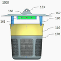
도 1은 본 발명의 일 실시예에 따른 포충기를 도시한 측면도이다.
도 2는 본 발명의 일 실시예에 따른 포충기를 도시한 단면도이다.
도 3은 본 발명의 일 실시예에 따른 포충기를 도시한 분해 사시도이다.
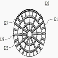
도 4는 본 발명의 일 실시예에 따른 포충기의 곤충 통과부를 나타낸 도면이다.
도 5는 본 발명의 일 실시예에 따른 포충기의 공기 집진부를 나타낸 도면이다.
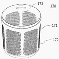
도 6은 본 발명의 일 실시예에 따른 포충기의 포집부를 나타낸 도면이다.
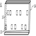
도 7 내지 도 9는 본 발명의 일 실시예에 따른 UV LED 모듈을 나타낸 도면이다.
도 10은 본 발명의 일 실시예에 따른 공기 집진부를 나타낸 도면이다.
도 11은 본 발명의 일 실시예에 따른 포충기의 메쉬부를 나타낸 도면이다.1 is a side view showing a catcher according to an embodiment of the present invention.
2 is a cross-sectional view illustrating a retainer according to an embodiment of the present invention.
3 is an exploded perspective view showing a catcher according to an embodiment of the present invention.
4 is a view showing an insect passage portion of a catcher according to an embodiment of the present invention.
5 is a view illustrating an air dust collection unit of a retainer according to an embodiment of the present invention.
6 is a view showing a trapping part of a catcher according to an embodiment of the present invention.
7 to 9 are views showing a UV LED module according to an embodiment of the present invention.
10 is a view showing an air dust collecting part according to an embodiment of the present invention.
11 is a view showing a mesh portion of a catcher according to an embodiment of the present invention.
본 발명은 이하에서 개시되는 실시예에 한정되는 것이 아니라 서로 다른 다양한 형태로 구현될 수 있으며, 단지 본 실시예는 본 발명의 개시가 완전하도록 하며 통상의 지식을 가진 자에게 발명의 범주를 완전하게 알려주기 위하여 제공되는 것이다.It is to be understood that the present invention is not limited to the disclosed embodiments, but may be embodied in many different forms and should not be construed as limited to the embodiments set forth herein. Rather, these embodiments are provided so that this disclosure will be thorough and complete, It is provided to inform.
본 명세서에서 일 요소가 다른 요소 '위' 또는 '아래'에 위치하는 것으로 언급되는 경우, 이는 상기 일 요소가 다른 요소 '위' 또는 '아래'에 바로 위치하거나 또는 그들 요소들 사이에 추가적인 요소가 개재될 수 있다는 의미를 모 두 포함한다. 본 명세서에서, '상부' 또는 '하부' 라는 용어는 관찰자의 시점에서 설정된 상대적인 개념으로, 관찰자의 시점이 달라지면, '상부' 가 '하부'를 의미할 수도 있고, '하부'가 '상부'를 의미할 수도 있다.Where an element is referred to herein as being located on another element "above" or "below", it is to be understood that the element is directly on the other element "above" or "below" And that it can be intervened. In this specification, the terms 'upper' and 'lower' are relative concepts set at the observer's viewpoint. When the viewer's viewpoint is changed, 'upper' may mean 'lower', and 'lower' It may mean.
복수의 도면들 상에서 동일 부호는 실질적으로 서로 동일한 요소를 지칭한다. 또한, 단수의 표현은 문맥상 명백하게 다르게 뜻하지 않는 한 복수의 표현을 포함하는 것으로 이해되어야 하고, '포함하다' 또는 '가지다' 등의 용어는 기술되는 특징, 숫자, 단계, 동작, 구성요소, 부분품 또는 이들을 조합한 것이 존재함을 지정하려는 것이지, 하나 또는 그 이상의 다른 특징들이나 숫자, 단계, 동작, 구성요소, 부분품 또는 이들을 조합한 것들의 존재 또는 부가 가능성을 미리 배제하지 않는 것으로 이해되어야 한다.Like numbers refer to like elements throughout the several views. It is also to be understood that the singular forms "a," "an," and "the" include plural referents unless the context clearly dictates otherwise, and the terms "comprise" Or combinations thereof, and does not preclude the presence or addition of one or more other features, integers, steps, operations, elements, components, or combinations thereof.
이하, 상기한 본 발명의 바람직한 실시예를 도면을 참조하여 구체적으로 살펴보기로 한다.Hereinafter, preferred embodiments of the present invention will be described in detail with reference to the drawings.
상기 기술한 바와 같이, 곤충, 예를 들어, 모기를 유인광에 의해 유인하고 흡입팬에 의해 포집하는 종래의 포충기는 친환경적이며 인체에 무해하다는 장점에도 불구하고, 유인 효율이 매우 낮거나, 과도한 전력을 사용해야 하거나, 또는 소음 발생이 지나치게 크다는 문제가 있었다. 따라서, 본 발명의 출원인은 상기 문제들을 해결하기 위해, 포충기의 각 구성을 제어하여 전력의 낭비 없이 곤충, 예를 들어, 모기의 유인 효과를 극대화 시키고 흡입 효과를 향상시키면서 동시에 소음 발생이 억제된 친환경적인 포충기를 개발하고자, 관련된 연구 및 제조 과정을 반복하였다. As described above, the conventional trapper, which attracts an insect such as a mosquito by the attracting light and collects it by the suction fan, is environmentally friendly and is harmless to the human body. However, the attracting efficiency is very low, , Or noise is excessively large. Therefore, the applicant of the present invention has found that, in order to solve the above-mentioned problems, the applicant of the present invention has an object of providing a method and apparatus for controlling insects, such as mosquitoes, In order to develop a catcher, related research and manufacturing process was repeated.
[제1실시예][First Embodiment]
도 1은 본 발명의 일 실시예에 따른 포충기를 도시한 측면도이며, 도 2는 본 발명의 일 실시예에 따른 포충기를 도시한 단면도이고, 도 3은 본 발명의 일 실시예에 따른 포충기를 도시한 분해 사시도이다.FIG. 1 is a side view showing a catcher according to an embodiment of the present invention, FIG. 2 is a cross-sectional view illustrating a catcher according to an embodiment of the present invention, and FIG. FIG.
이하, 도 1 내지 도 3을 참조하여, 본 발명의 일 실시예에 따른 포충기(1000)의 각 구성을 상세하게 설명한다. Hereinafter, with reference to FIG. 1 to FIG. 3, each configuration of the
본 발명의 일 실시예에 따른 상기 포충기(1000)는 자외선으로 곤충을 유인하여 포집하기 위하여, 몸체(110), 상기 몸체(110) 상에 탈착 가능하게 배치되고 선택적으로 곤충을 통과시키는 곤충 통과부(120), 상기 몸체(110) 하부에 배치된 공기집진부(130), 상기 공기 집진부(130)와 상기 곤충 통과부(120) 사이에 위치하는 모터(140), 상기 모터(140)와 상기 공기 집진부(130) 사이에 위치하고, 상기 모터(140)에 의해 회전하는 흡입팬(150), 상기 곤충 통과부(120) 상부에 배치되고, UV LED 모듈이(161)가 장착된 UV LED 설치부(160) 및 상기 공기 집진부(130) 하부에 탈착 가능하게 배치되어 곤충을 포집하는 포집부(170)를 포함할 수 있다.The
본 발명에서 지칭하는 곤충은 그 종류를 한정하지 않고 다양한 종류의 날벌레를 포함하며, 특히 모기를 지칭할 수 있다.The insects referred to in the present invention are not limited to the kinds of insects, but may include various kinds of insects, and may particularly refer to mosquitoes.
몸체(110)In the
상기 몸체(110)는 형상이 특별히 한정되지 않으나 상기 흡입팬(150)이 내부에 실장된다는 점에서 원통형상일 수 있고, 재질 또한 특별히 한정되지 않으나 실내 또는 실외에서 장기간 사용이 가능한 동시에 제조 단가를 크게 높이지 않도록 하기 위해 상용되는 플라스틱계 재질로 제조될 수 있다. 상기 몸체(110)는 상하로 공기가 통과할 수 있도록 상하로 개방된 구조를 가진다. 또한, 상기 몸체(110)의 높이는 2 cm 내지 20 cm, 바람직하게는 3 cm 내지 10 cm 일 수 있다.Although the shape of the
도 2 및 도 3을 참조하면, 상기 몸체(110)의 상부에서부터 하부로 곤충 통과부(120), 모터(140), 및 흡입팬(150)이 상기 몸체(110)에 실장될 수 있다.2 and 3, the
도 4는 본 발명의 일 실시예에 따른 포충기의 곤충 통과부(120)를 나타낸 도면이다.4 is a view showing an
도 4를 참조하면, 상기 곤충 통과부(120)는 선택적으로 곤충이 통과할 수 있는 복수의 곤충 통과 구멍(121)을 포함하는 격자 형태이며, 상기 복수의 곤충 통과 구멍은 원형 부재(122) 및 방사상 부재(123)에 의해 형성될 수 있다. 구체적으로 포집 대상 곤충의 평균 크기를 고려하여 상기 곤충 통과 구멍(121)의 크기가 조절될 수 있고, 도 4에 나타낸 바와 같이 상기 곤충 통과부(120)가 격자 형태인 경우 낮은 제조 단가로 상기 곤충 통과 구멍(121)의 크기를 효과적으로 제어할 수 있다.4, the
종래 상용되던 흡인팬을 이용하여 곤충을 포집하는 포충기의 경우, 모기 보다 체적이 큰 나비, 잠자리, 파리 등의 곤충이 함께 포집되어 포집부 교환 주기가 빠르거나, 해충이 아닌 유익한 곤충까지 포집되어 생태계에 악영항을 끼치는 문제가 있었다. 또한, 체적이 큰 곤충이 흡입팬에 달라붙게 되어 모터의 수명이 단축되거나 흡입팬에서 소음이 발생하는 문제가 있었다. 따라서, 본 발명의 발명자들은 상기 포충기(1000)가 곤충을 선택적으로 흡입할 수 있도록 상기 곤충 통과 구멍(122)의 크기를 제어하는 동시에 경제적으로 상기 곤충 통과부(120)를 제조하였다.In the case of a trapper collecting insects using a conventional suction fan, insects such as butterflies, dragonflies, and flies, which are larger in volume than mosquitoes, are trapped at the same time, There was a problem of bad influence on the. In addition, insects having a large volume stick to the suction fan, shortening the service life of the motor and generating noise in the suction fan. Accordingly, the inventors of the present invention have economically produced the
상기 복수의 곤충 통과 구멍(121)은 상기 곤충 통과부(120)의 중앙을 중심으로 하는 복수의 원형 부재(122) 및 방사상 부재(123)에 의해 구분되고 중심각이 20 ˚ 내지 40 ˚ 인 부채꼴 형태이며, 각 원형 부재(122)는 인접 원형 부재(123)와 1.0 cm 내지 1.5 cm 가 이격되는 형태일 수 있으며, 상기 수치 범위 내에서 상기 곤충 통과 구멍(121) 한 개의 면적이 100 ㎜2 내지 225 ㎜2 일 수 있다. 따라서 곤충, 특히 모기를 선택적으로 통과시키는 반면, 나비, 잠자리, 파리 등 몸체 크기가 큰 곤충은 상기 포충기(1000) 내부로 포집되지 않도록 하여, 모터의 내구성이 열악해지거나, 상기 흡입팬(150)에서 발생하는 소음을 감소시킬 수 있다.The plurality of insect through
또한, 상기 흡입팬(150)은 곤충이 상기 흡입팬(150)에 달라붙지 않고 상기 흡입팬(150) 하부로 유입되도록 제어하는 것이 바람직하다. 종래 상용되던 흡입팬을 이용하여 곤충을 포집하는 포충기의 경우, 팬날개에 곤충이 달라붙게 되어 흡입팬의 회전 반경이 균일하지 않게 됨으로써, 모터의 내구성이 열악해지거나 소음이 발생하는 문제가 있었다. 그러나, 팬날개에 곤충이 달라붙지 않도록 하기 위해 흡입팬의 회전 속도를 감소시키는 경우 포충기에 인접한 곤충의 포집 효율이 현저하게 감소하는 문제가 있었다. 즉, 곤충은 풍속 0.8 m/s 이상에서 비행을 멈추는 경향이 있으나 풍속이 지나치게 높은 경우 곤충이 기류로부터 탈출을 시도하게 되므로, 본 발명의 발명자들은 상기 팬날개(151)에 곤충이 달라붙지 않도록 하는 동시에 모기가 비행을 멈추어 상기 흡입팬(150)에서 발생한 흡입 기류에 의해 포집되는 상기 포충기(1000)를 제조였다.In addition, it is preferable that the
이를 위해, 상기 팬날개(151)가 2 개 내지 6 개, 바람직하게는 3 개 또는 4 개 이며, 상기 흡입팬(150)의 회전속도가 1500 rpm 내지 2800 rpm, 바람직하게는 1800 rpm 내지 2800 rpm 일 수 있다. 상기 팬날개(151)의 개수가 2개 미만 또는 상기 흡입팬(150)의 회전속도가 1500 rpm 미만인 경우 모기 포집효과가 감소할 수 있고, 상기 팬날개(151)의 개수가 6개 초과 또는 상기 흡입팬(151)의 회전속도가 2800 rpm 초과인 경우 모기 사체가 상기 흡입팬(151)에 지나치게 많이 달라붙거나 소음이 38 dBA 이상으로 높아지는 문제점이 발생할 수 있다.For this, the number of the
또한, 상기 팬날개(151)는 평평하지 않고 일정 또는 일정하지 않은 곡률로 구부러진 형태일 수 있으며, 상기 구부러진 형태의 팬날개(151)는 최하단(最下段)과 최상단(最上段)의 높이 차가 5 ㎜ 내지 30 ㎜ 일 수 있다. 한편, 상기 흡입팬(150)은 지름이 60 ㎜ 내지 120 ㎜ 일 수 있고, 바람직하게는 80 ㎜ 내지 110 ㎜ 일 수 있다. 그리고, 상기 흡입팬(150)과 상기 몸체(110) 내벽의 최단거리를 1 ㎜ 내지 5 ㎜ 로 제어하여, 상기 흡입팬(150)에 의한 소음을 최소화하는 동시에 흡입 기류를 효과적으로 형성할 수 있다. The bent
또한, 상기 몸체(110)로부터 상기 UV LED 설치부(160)가 이격된 수직 거리 및 상기 몸체(110)의 높이 비가 1 : 1 내지 1 : 2 이고, 상기 포집부(170)로부터 상기 UV LED 설치부(160)가 이격된 수직 거리 및 상기 포집부(170)의 높이 비가 1 : 0.5 내지 1 : 2 일 수 있다. 상기 비율 범위 내에서 상기 흡입팬(150)에 상기 곤충이 달라붙지 않으면서 상기 포충기(1000)에 인접한 곤충이 용이하게 흡입될 수 있다.The vertical distance between the UV
따라서, 상기 수치 범위 내에서 상기 곤충 통과부(120) 및 상기 UV LED 설치부(160) 사이에서 상기 흡입팬(150)에 의해 형성된 기류(氣流)의 속도가 0.5 m/s 내지 2.5 m/s, 바람직하게는 0.6 m/s 내지 2.5 m/s, 더욱 바람직하게는 0.7 m/s 내지 2.5 m/s, 예를 들어 0.7 m/s 내지 2.0 m/s 가 되도록 제어될 수 있고, 곤충이 상기 흡입팬(150)에 달라붙지 않으면서 동시에 곤충이 비행을 멈추고 높은 효율로 상기 포집부(170)에 포집될 수 있으며, 상기 흡입팬(150)에 의한 소음 발생을 억제할 수 있다.Accordingly, the speed of the air flow formed by the
또한, 상기 곤충 통과부(120) 하부에 상기 모터(140)가 실장되고, 그 하부에 상기 흡입팬(150)이 상기 모터(140)에 장착되는 구성을 차용하여 상기 포충기(1000)는 상기 모터(140) 및 상기 흡입팬(150)에 의해 발생하는 소음을 현저하게 감소시킬 수 있다.The
공기 air 집진부Dust collector (130)(130)
도 5 및 도 10은 본 발명의 일 실시예에 따른 공기 집진부를 나타낸 도면이다.5 and 10 are views showing an air dust collector according to an embodiment of the present invention.
상기 공기 집진부(130, 130')는 상기 몸체(110)의 하부에 장착되어 상기 흡입팬(150)에 의해 유입된 곤충이 상기 포집부(170)로 토출되도록 공기 집진부살(131), 공기 집진부 측면구(口)(132), 및 공기 집진 토출구(133)를 포함할 수 있고, 상기 공기 집진부(130)는 상기 흡입팬(150)으로부터 이격될수록 직경이 좁아지는 콘(cone) 형상일 수 있다. 즉, 상기 공기 집진부(130)는 상기 흡입팬(150)에 의해 발생한 기류를 분산시키지 않고 하부의 상기 포집부(170)로 효과적으로 보낼 수 있도록 하기 위해 콘(cone) 형상인 것이 바람직하고, 상기 공기 집진부 측면구(132)를 포함하여 상기 흡입팬(150)에 의해 발생한 기류가 상기 포충기(1000) 외부로 효과적으로 빠져나가도록 할 수 있다. 상기 공기 집진부 측면구(132)의 형태는 특별히 제한되지 않고, 도 10에 나타낸 바와 같이 메쉬 형상일 수 있고, 상기 메쉬 형상에 의해 형성된 구멍의 면적은 곤충, 특히 모기가 통과할 수 없도록 제어하는 것이 바람직하다. The
따라서, 본 발명의 일 실시예에 따른 상기 포충기(1000)는 상기 흡입팬(150)에 의해 유입된 곤충이 상기 포집부(170)에 포집된 후 상기 공기 집진부(130)를 통해 상기 포충기(1000) 외부로 빠져 나가지 못하도록 제조될 수 있다. Therefore, in the
한편, 상기 공기 집진 토출구(133)의 직경과 상기 흡입팬(150)의 직경의 비가 1 : 2 내지 1 : 9 를 만족할 수 있고, 바람직하게는 1 : 3 내지 1 : 5 일 수 있고, 상기 비율 범위 내에서 상기 흡입팬(150)에 의한 풍속 제어가 용이할 수 있다.On the other hand, the ratio of the diameter of the air collecting and discharging
포집부Collection section (170)(170)
도 6은 본 발명의 일 실시예에 따른 포충기의 포집부를, 도 11은 본 발명의 일 실시예에 따른 포충기의 메쉬부를 나타낸 도면이다.FIG. 6 is a view showing a trapping part of a catcher according to an embodiment of the present invention, and FIG. 11 is a view showing a mesh part of a catcher according to an embodiment of the present invention.
도 6 및 도 11을 참조하면, 상기 포집부(170)는 상기 흡입팬(150)에 의해 공기가 외부로 토출되는 메쉬부(171)를 포함할 수 있다. 또한, 상기 메쉬부(171)는 메쉬부살(172) 및 상기 메쉬부살(172) 사이에 형성되어 상기 흡입팬(150)에 의해 형성된 기류가 상기 포집부(170) 외부로 토출되는 메쉬부 구멍(173)을 포함할 수 있고, 포집된 곤충이 빠져 나가지 못하면서 공기 흐름은 원할하도록 하기 위해 상기 메쉬부 구멍(173)의 직경이 1 ㎜ 내지 3 ㎜ 일 수 있다.6 and 11, the collecting
구체적으로, 상기 포집부(170)에 상기 메쉬부(171)가 1 개 내지 10 개 일 수 있고, 예를 들어 3 개 내지 8 개 일 수 있으며, 상기 메쉬부(171)한 면당 메쉬부 구멍(173)이 300 개 내지 700 개, 바람직하게는 400 개 내지 600 개 일 수 있다.For example, the number of the
또한, 상기 곤충 통과 구멍(121) 면적의 총 합과 상기 메쉬부 구멍(173) 면적의 총 합의 비가 1 : 0.8 내지 1 : 3.0, 바람직하게는 1 : 0.8 내지 1 : 2.0 일 수 있다. 상기 비율 범위 내에서 곤충이 상기 포집부(170) 체적의 1/2까지 포집되어도 상기 포충기(1000) 외부로 토출되는 공기의 흐름이 저해되지 않을 수 있다.The ratio of the total sum of the areas of the insect through
즉, 상기 포집부(170)는 상기 흡입팬(150)에 의해 발생한 기류가 상기 포충기(1000) 외부로 효과적으로 토출되도록 할 수 있고, 따라서 상기 포집부(170) 내에 포집된 모기가 건조 치사될 수 있다. That is, the collecting
UV LED UV LED 설치부Installation part (160)(160)
도 1 내지 도 3을 참조하면, 상기 UV LED 설치부(160)는 판 형태일 수 있다. 구체적으로, 상기 UV LED 설치부(160)는 상기 몸체(110)와 유사한 형태 및/또는 크기로 형성될 수 있고, 예를 들어 상기 몸체부(110)가 원형인 경우 상기 UV LED 설치부(160)는 상기 몸체부(110)와 유사한 크기의 원판 형태일 수 있다. 1 to 3, the UV
따라서, 상기 UV LED 설치부(160)는 상기 흡입팬(150)에 의해 형성된 기류가 상기 UV LED 설치부(160)와 상기 몸체(110) 사이에 형성된 공간으로 유입되도록 제한함으로써, 상기 포충기(1000) 내로 흡입 기류 발생 효율을 향상시킬 수 있고, 그 결과 상기 흡입팬(150)의 회전속도를 불필요하게 높게 제어할 필요가 없으므로 소음 발생 또한 최소화할 수 있다. Therefore, the UV
한편, 상기 몸체(110)와 상기 UV LED 설치부(160) 사이의 공간으로 곤충이 유입되도록 상기 몸체(110) 상에 상기 UV LED 설치부(160)를 이격시켜 지지하는 지지대(180)가 배치될 수 있고, 상기 UV LED 설치부(160)에는 UV LED 모듈(161)이 실장되고, 추가적으로 UV LED 설치부 갓(162)이 장착될 수 있다.A
또한, 상기 지지대(180)의 형태 및 개수는 특별히 제한되지 않으나, 상기 UV LED 설치부(160)를 안정적으로 지지하는 동시에 곤충이 유입되는 공간이 상기 지지대(180)에 의해 제한되는 영역을 최소화할 수 있다는 점에서, 상기 지지대(180) 두 개가 마주보는 방향으로 장착될 수 있다.Although the shape and the number of the
상기 UV LED 설치부(161)는 상기 몸체(110)로부터 수직으로 1 cm 내지 10 cm, 바람직하게는 3 cm 내지 5 cm 가 이격된 거리에 위치하도록 상기 지지대(180)의 높이를 제어 할 수 있고, 구체적으로 상기 지지대의 높이와 상기 UV LED 설치부(161)가 상기 몸체(110)로부터 수직으로 이격된 거리가 동일할 수 있다. 상기 UV LED 설치부(161)가 상기 몸체(110)로부터 수직으로 이격된 거리가 3 cm 보다 짧은 경우 곤충이 유입되는 구멍이 지나치게 작아 곤충 포집 효율이 저하될 수 있고, 5 cm 보다 긴 경우 상기 흡입팬(150)에 의해 형성되는 기류가 충분한 세기로 형성되지 않아 곤충 포집 효율이 저하되는 문제가 발생할 수 있다.The UV
따라서, 자외선으로 곤충이 유인되어 상기 포충기(1000)에 근접하면 상기 흡입팬(150)에 의해 형성된 흡입 기류에 의하여 곤충이 상기 몸체(110)와 상기 LED 설치부(160) 사이의 공간으로 유입되고, 상기 곤충 통과부(120) 및 상기 흡입팬(150)을 통과하여, 상기 공기 집진부(130) 하부의 포집부(170)에 포집될 수 있다.Accordingly, when an insect is attracted by the ultraviolet rays and comes close to the
도 3을 참조하면, 상기 UV LED 모듈(161)은 상기 UV LED 설치부(160) 하면에 장착될 수 있고, 도 3에 도시한 바와 같이 상기 UV LED 설치부(160) 상단에 설치된 탈착(脫着)이 가능한 형태의 UV LED 설치부 갓(162)을 탈착시킨 후, 상기 UV LED 모듈(161)을 상기 UV LED 설치부(160) 상부에서 하부로 삽입하여 상기 UV LED 모듈(161)을 실장할 수 있다. 또한, 상기 UV LED 설치부(160)에 장착된 상기 UV LED 모듈(161)은 전원에 전기적으로 연결될 수 있다.3, the
본 발명의 일 실시예에 따른 상기 포충기(1000)는 상기 UV LED 모듈(161)이 지면과 수평 방향으로 빛이 조사되도록 상기 UV LED 설치부(160)에 장착될 수 있다. 곤충은 비행 시, 지면에서 약 1.5 m 높이에서 가장 오랜 시간을 머물게 되는데, 상기 포충기(1000)를 지면에서 약 1.5 m 높이에 설치하는 경우, 상기 UV LED 모듈(161)의 지면과 수평 방향으로 조사되는 빛에 의해 곤충이 강한 자극을 받어 상기 포충기(1000)로 효과적으로 유인될 수 있다.The
또한, 도 3에 도시한 바와 같이, 상기 UV LED 설치부 갓(162) 상면에 UV LED 설치부 갓 걸이(163)를 추가로 설치하여 상기 포충기(1000)를 실외에서 사용 시 약 1.5 m 높이의 나뭇가지 등에 매달아서 편리하게 사용할 수 있다.3, a
상기 UV LED 설치부(160)는, 상기 UV LED 모듈(161)에 대응하도록 형성되며 상기 UV LED 모듈(161)을 보호하는 UV LED 모듈 커버가 장착되어, 외부 먼지 또는 곤충의 접근에 의해 상기 UV LED 모듈(161)이 파손되는 현상을 방지할 수 있고, 상기 UV LED 모듈 커버는 투명한 것이 바람직하다.The UV
상기 UV LED 모듈 커버는 다양한 형상으로 가공됨으로써, 상기 UV LED 모듈(161)로부터 방출되는 광을 확산시키거나 소정의 방향으로 수렴시키는 렌즈의 역할을 수행할 수 있다. 상기 UV LED 모듈 커버는 일 예로서, 글라스, 쿼츠(quartz) 등의 재질을 포함할 수 있다. 글라스, 쿼츠 등에 비해 성형성이 좋고 취급이 쉬우며 내구성이 좋은 폴리머도 적용할 수 있으나, 폴리머는 분자 구조상 원자핵 주위에 존재하며 UV에 해당하는 공진주파수를 갖는 전자구름(electron cloud)에 의해 400 ㎚ 이하 파장(자외선 파장 영역)의 광이 흡수되어 광 투과율이 현저히 떨어질 뿐만 아니라 자외선에 의해 재질 자체가 열화되기 때문에 일반적으로 폴리머를 상기 UV LED 모듈 커버로 사용하지 않은 것이 바람직하다.The UV LED module cover may be formed into various shapes to function as a lens for diffusing or converging light emitted from the
그러나, 단량체 비율이 약 80 % 이상 높은 PMMA(poly methyl methacrylate)는 주로 탄소와 수소로 구성되어 전자구름이 희박하기 때문에 UV 투과율이 높기 때문에 이러한 재질을 사용하여 상기 UV LED 모듈 커버를 구성하는 것이 바람직하다.However, since PMMA (poly methyl methacrylate) having a monomer ratio of about 80% or more is composed mainly of carbon and hydrogen and has a high UV transmittance because of an electron cloud is thin, it is preferable to construct the UV LED module cover using such a material Do.
또한, 자외선과 반응하지 않는 안정적인 물질인 불소계 폴리머를 사용할 수도 있다. 일 예로, 석영이나 PMMA 보다 자외선 투과율이 낮은 점을 감안하여 상대적으로 플렉시블한 물성을 가지도록 구성하면서 두께를 얇게 하는 것이 좋다. 즉, 불소계 폴리머를 상기 UV LED 모듈 커버로 사용하기 위해서는 자외선 투과율을 고려해야 하고, 불소계 폴리머의 경우 석영이나 PMMA 보다는 자외선 투과율이 낮기 때문에 두께가 얇을 수록 자외선 투과율이 높아지게 되지만, 상기 UV LED 모듈 커버의 두께를 얇게 하면 폴리머의 취성에 의해 작은 충격에도 쉽게 부서질 염려가 있으므로, 재질 자체를 플렉시블한 연성 재질로 구성하여 취성을 감소시키는 것이 바람직하다.Further, a fluorine-based polymer that is a stable substance that does not react with ultraviolet rays may be used. For example, it is preferable to make the thickness thinner while having a relatively flexible physical property in consideration of the fact that the ultraviolet transmittance is lower than that of quartz or PMMA. That is, in order to use the fluoropolymer as the UV LED module cover, the ultraviolet transmittance must be considered. In the case of the fluoropolymer, since the ultraviolet transmittance is lower than that of the quartz or PMMA, the thinner the thickness, the higher the ultraviolet transmittance. It is preferable that the material itself is made of a flexible soft material so as to reduce the brittleness.
한편, 도 3에 도시하지 않았으나, 상기 LED 설치부(160)는 하면에 상기 UV LED 모듈(161)에 의해 조사된 UV를 반사시킬 수 있는 재료가 부착 또는 코팅될 수 있다. 상기 UV를 반사시킬 수 있는 재료는 특별히 한정되지 않으며, 은 또는 알루미늄 등의 재질이 부착될 수 있고, 은 또는 알루미늄 막이 상기 UV LED 설치부(160) 하면에 코팅될 수 있으며, 조사된 광을 산란시키기 위한 다양한 형태의 굴곡 또는 요철 패턴이 추가될 수 있다.3, a material capable of reflecting the UV light irradiated by the
또한, 도 1 내지 도 3을 참조하면, 상기 UV LED 설치부(160) 상면에 수평 방향으로 상기 UV LED 설치부(161) 보다 연장되어 형성된 UV LED 설치부 갓(162)이 장착될 수 있다. 상기 UV LED 설치부 갓(162)은 형태 및 재질이 특별히 한정되지 않으나, 상기 UV LED 설치부(160)와 동일한 재질 및 형태일 수 있고, 예를 들어, 상기 UV LED 설치부(160)가 원형인 경우, 상기 UV LED 설치부 갓(162)은 상기 UV LED 설치부(160)와 중심이 동일하고 직경이 보다 긴 형태일 수 있다. Referring to FIGS. 1 to 3, a UV
바람직하게는, 상기 UV LED 설치부 갓(162)의 직경은 상기 UV LED 설치부(160)의 직경 보다 3.5 cm 내지 7 cm 가 더 길게 형성될 수 있고, 3.5 cm 보다 짧은 경우 상기 흡입팬(150)에 의해 형성되는 기류가 측면 또는 하면으로 집중되지 않고 분산될 수 있고, 7 cm 보다 긴 경우 상기 UV LED 모듈(161)에서 조사되는 빛의 양을 불필요하게 차단하는 문제가 발생할 수 있다. 구체적으로, 상기 UV LED 설치부(160)의 직경이 8 cm 내지 20 cm 이고, 상기 UV LED 설치부 갓(162)의 직경은 10 cm 내지 25 cm 인 범위에서, 상기 UV LED 설치부 갓(162)의 직경이 상기 UV LED 설치부(160)의 직경 보다 3.5 cm 내지 7 cm 가 더 길게 형성될 수 있다. 또한, 상기 UV LED 설치부 갓(162)의 외주면이 직선 또는 곡선 형태로 상기 UV LED 설치부 보다 낮게 연장되어 형성될 수 있고, 구체적으로는 약 6 ㎜ 내지 10 ㎜ 가 낮게 형성되어, 상기 포충기(1000) 내로의 흡입 기류를 효과적으로 형성할 수 있다.Preferably, the diameter of the UV
또한, 본 발명의 일 실시예에 따른 상기 포충기(1000)는 상기 UV LED 설치부(160) 및 상기 UV LED 설치부 갓(162)의 직경이 상기 수치범위인 경우, 상기 UV LED 설치부 갓(162)으로부터 지면 방향으로 상기 몸체 상단의 높이까지 연장된 영역에서 측정된 상기 흡입팬에 의해 형성된 기류의 속도가 0.5 m/s 내지 3.0 m/s, 바람직하게는 0.5 m/s 내지 2.5 m/s, 더욱 바람직하게는 0.6 m/s 내지 2.5 m/s, 예를 들어 0.7 m/s 내지 2.5 m/s, 구체적인 예로 0.7 m/s 내지 2.0 m/s 로 형성되어, 모기가 비행을 정지하고 상기 포충기(1000) 내부로 유입될 수 있는 최적의 풍속이 형성될 수 있다.In the
한편, 상기 기술한 바와 같이 상기 UV LED 설치부(161)는 상기 곤충 통과부(120)로부터 2 cm 내지 5 cm 가 이격된 거리에 위치하도록 하는 동시에 상기 UV LED 설치부 갓(162)의 직경을 제어함으로써, 상기 흡입팬(150)에 의해 발생한 기류가 외부 바람 등에 의해 영향을 받지 않고 유지될 수 있도록 하여, 조사된 빛에 의해 유인된 곤충을 안정적으로 상기 곤충 통과부(120)로 흡입할 수 있다.Meanwhile, as described above, the UV
UV LED 모듈(161, 261, 361)The UV LED module (161, 261, 361)
도 7 내지 도 9는 본 발명의 일 실시예에 따른 UV LED 모듈을 나타낸 도면이다.7 to 9 are views showing a UV LED module according to an embodiment of the present invention.
상기 UV LED 모듈(161, 261, 361)은 자외선, 가시광선, 적외선 중 적어도 하나의 파장을 가지는 광을 제공할 수 있고, 바람직하게는 자외선을 제공할 수 있다. 곤충이 유인되는 파장과 관련하여, 파리 및 벼멸구의 경우 약 340 nm 또는 약 575 nm의 파장의 빛을 선호하며, 나방과 모기의 경우 약 366 nm 파장의 빛을 선호한다고 보고되고 있다. 또한, 기타 일반적인 해충의 경우, 약 340 nm 내지 380 nm 파장의 빛을 상대적으로 선호한다고 보고되고 있다. 다른 예로서, 곤충이 유인되는 가시광선 영역의 파장과 관련하여, 한국공개특허번호 2013-0049475 또는 한국공개특허번호 2014-0010493에서는, 흰색, 노란색, 빨간색, 녹색, 파란색 광에 의한 곤충의 유인활성을 개시하고 있다. The
바람직하게는, 상기 UV LED 모듈(161, 261, 361)에서 발산하는 빛의 파장은 340 ㎜ 내지 390 ㎜ 일 수 있고, 곤충, 특히 모기는 강하게 유인되는 반면 인체에의 유해성이 낮다는 점에서 약 365 ㎜ 의 파장의 빛이 조사되도록 제어하는 것이 더욱 바람직하다.Preferably, the wavelength of the light emitted from the
상기 UV LED 모듈(161, 261, 361)은 지지 기판(164) 상에 실장되는 적어도 하나 이상의 COB(chip on board) 타입의 UV LED 칩(165) 또는 적어도 하나 이상의 UV LED 패키지를 포함할 수 있고, 상기 UV LED 모듈(161)은 복수의 열로 배열되는 UV LED 칩(165) 또는 UV LED 패키지를 포함할 수 있으며, 상기 지지 기판(164)이 과열되는 현상을 억제하기 위해 상기 UV LED 칩(165) 또는 상기 UV LED 패키지는 지그재그(zigzag) 형태일 수 있다.The
상기 지지 기판(164)은 소정의 두께를 가지는 패널 형태를 가질 수 있고, 내부에 집적 회로 또는 배선을 구비하는 인쇄회로기판을 포함할 수 있다. 일 예로서, 상기 지지 기판(164)은 상기 UV LED 칩(165)이 실장될 영역에 회로패턴을 구비하는 인쇄회로기판일 수 있고, 상기 지지 기판(164)은 금속, 반도체, 세라믹, 폴리머 등의 재질로 이루어질 수 있다.The
구체적으로, 상기 UV LED 모듈(161, 261, 361)은 긴 평판 형상의 PCB 상에 상기 UV LED 칩(165)이 실장된 형태일 수 있다. 상기 UV LED 칩(165)은 PCB의 길이 방향을 따라 복수 개, 예를 들어 4 개 내지 10 개가 이격 설치될 수 있다. 상기 PCB의 타면에는 상기 UV LED 칩(165)에서 발생하는 열을 방열하기 위한 방열핀이 설치될 수 있고, 상기 UV LED 모듈(161, 261, 361)의 양 단에는 전원단자와 접속하여 PCB에 전원을 공급하는 단자가 설치될 수 있다.Specifically, the
상기 UV LED 모듈(161, 261, 361)은 입력 전압이 12V, 입력 전류가 75 mA 내지 85 mA 일 때, 800 mA 내지 2000 mA, 바람직하게는 1000 mA 내지 1500 mA 의 전력을 소모하도록 제조할 수 있다. 상기 수치 범위 내에서 365 ㎜ 파장의 빛으로 곤충을 효과적으로 유인할 수 있는 동시에 인체에는 무해한 파장 및 세기의 자외선을 조사하면서도 전력 낭비를 최소화 할 수 있다.The
상기 UV LED 모듈(161, 261, 361)은 상기 지지 기판(164)의 한 면에 실장된 UV LED 칩(165) 또는 상기 UV LED 패키지는 다른 면에 실장된 UV LED 칩(165) 또는 상기 UV LED 패키지와 겹치지 않도록 상기 지지 기판(164) 상에 배열되는 형태일 수 있고, 구체적인 형태는 특별히 제한되지 않으나 복수의 열로 배열되는 형태이거나 지그재그(zigzag) 형태일 수 있다. 따라서, 본 발명의 일 실시예에 따른 상기 포충기(1000)는 빛 조사 범위를 크게 확장시키면서 전력 소모를 최소화할 수 있고, 상기 UV LED 칩(165)에서 발생하는 열을 효과적으로 방출하여 상기 UV LED 모듈(161, 261, 361)의 내구성을 향상시킬 수 있다.The
상기 UV LED 모듈(161, 261, 361)로 공급되는 전기적 에너지가 빛 에너지 및 열 에너지 형태로 변환되면서 상기 UV LED 칩(165)에서 열이 발생하는 바, 상기 UV LED 칩(165)으로부터 5 ㎜ 이내로 이격된 공간에서 측정한 온도가 30 ℃ 내지 60 ℃ 일 수 있다. 곤충, 특히 모기는 체온과 유사한 약 38 ℃ 내지 40 ℃ 의 온도에 의해 강하게 유인되므로, 상기 UV LED 모듈(161, 261, 361)에 의한 유인 효과에 더하여 상기 UV LED 모듈(161, 261, 361)에 의해 발생된 열에 의해 상기 포충기(1000)로 곤충을 강하게 유인할 수 있다. The electric energy supplied to the
따라서, 본 발명의 일 실시예에 따른 상기 포충기(1000)는 입력 전압이 12V, 입력 전류가 75 mA 내지 85 mA 일 때, 800 mA 내지 2000 mA, 바람직하게는 1000 mA 내지 1500 mA 의 전력을 소모하도록 제조된 상기 UV LED 모듈(161, 261, 361)을 사용하고, 상기 지지 기판(164)의 한 면에 실장된 UV LED 칩(165) 또는 상기 UV LED 패키지는 다른 면에 실장된 UV LED 칩(165) 또는 상기 UV LED 패키지와 겹치지 않도록 상기 지지 기판(164) 상에 배열됨으로써, 전력 소모를 최소화 하고 인체에 무해한 반면 곤충 유인 효율이 높은 빛을 조사하는 동시에 상기 포충기(1000) 주변에 곤충의 유인 효과가 높은 온도를 형성할 수 있도록 열을 발생시킬 수 있다.Thus, the
[제2실시예][Second Embodiment]
본 발명의 상기 포충기(2000, 도면에 미도시)의 제2실시예는, 광촉매필터부가 설치된 점을 제외하고 상기 제1실시예의 구성을 차용할 수 있고, 이하 상기 광촉매필터부에 관한 구성을 상세히 기술한다.The second embodiment of the retainer 2000 (not shown in the drawing) of the present invention can borrow the structure of the first embodiment except that the photocatalytic filter unit is provided. Hereinafter, the structure of the photocatalytic filter unit will be described in detail .
상기 광촉매필터부는 상기 UV LED 모듈(161)에 의해 조사된 UV를 촉매로 하여 탈취 기능을 수행할 수 있는 외에, 이산화탄소를 발생시킬 수 있다. 상기 광촉매필터부의 설치 위치는 상기 포충기(2000)에서 상기 UV LED 모듈(161)에서 발생한 UV가 조사될 수 있는 곳이라면 특별히 제한되지 않고, 상기 몸체(110), 곤충 통과부(120), 공기 집진부(130), UV LED 설치부(160), UV LED 설치부 갓(162), 메쉬부(180) 등에 설치될 수 있으며, 바람직하게는 상기 UV LED 설치부(160) 및/또는 상기 UV LED 설치부 갓(162) 하면에 설치될 수 있다.The photocatalytic filter unit can perform a deodorizing function using the UV light irradiated by the
상기 광촉매필터부는 상기 포충기에서 돌출된 형태가 아닌 매립된 형태인 것이 바람직하다. 구체적으로, 상기 포충기(1000)에서 발생한 기류와 측면에서 접촉될 수 있는 측면 매립형인 경우, 상기 포충기(1000) 내부로 곤충의 유입 및 공기의 유입량을 방해하지 않으면서, 상기 포충기(1000) 내부 공간을 효율적으로 구성할 수 있다.It is preferable that the photocatalytic filter portion is not a protruding shape but a buried form. In other words, when the
상기 광촉매필터부는 비제한적인 프레임에 광촉매층이 도포되는 형태일 수 있고, 일 예로 메탈폼(metal foam), 탄소폼(carbon foam) 등의 다공성 물질 내에 광촉매층이 도포되는 형태일 수 있고, 세라믹 내에 도포되는 형태일 수도 있다.The photocatalytic filter unit may be configured to apply a photocatalyst layer to a non-restrictive frame. For example, the photocatalytic filter unit may be formed by coating a photocatalyst layer in a porous material such as metal foam or carbon foam. Or the like.
상기 광촉매층은 광촉매 매질로서 기능하는 물질, 예컨대, 티타늄산화물(TiO2), 실리콘산화물(SiO2), 텅스텐산화물(WO3), 산화아연(ZnO), 산화지르코늄(ZrO2), 산화주석(SnO2), 산화세륨(CeO2), 산화텅스텐(WO3), 산화철(FeO3), 황화아연(ZnS), 황화카드뮴(CdS), 및 티탄산스트론튬(SrTiO3) 로 이루어진 군에서 선택되는 어느 하나 이상의 화합물을 포함하는 층으로 형성될 수 있다. 구체적인 일 예로서, 상기 광촉매층은 티타늄산화물(TiO2) 코팅층으로 제공될 수 있고, 또는 상기 광촉매필터부에서 세라믹과 접촉되는 부분에 식용유나 귤껍질 액을 도포하는 형태로 제공될 수 있다.The photocatalyst layer may be formed of a material that functions as a photocatalytic medium such as titanium oxide (TiO 2 ), silicon oxide (SiO 2 ), tungsten oxide (WO 3 ), zinc oxide (ZnO), zirconium oxide (ZrO 2 ) SnO 2), which is cerium oxide (CeO 2), tungsten oxide (WO 3), iron oxide (FeO 3), selected from the group consisting of zinc sulfide (ZnS), cadmium sulfide (CdS), and strontium titanate (SrTiO 3) May be formed of a layer comprising at least one compound. As a specific example, the photocatalyst layer may be provided as a titanium oxide (TiO 2 ) coating layer, or may be provided in a form of applying cooking oil or a tangerine peel liquid to a portion of the photocatalytic filter portion in contact with the ceramic.
상기 광촉매층은 탈취 효과 외에 곤충, 특히 모기 유인 효과가 높은 CO2를 발생시킬 수 있다. 구체적으로, 상기 광촉매층에 상기 UV LED 모듈(161)로부터 광촉매 반응을 유도하는 광이 조사되면, 공지의 광촉매 반응에 의해, 강한 환원성을 가지는 라디칼이 발생할 수 있다. 상기 라디칼에 의해 상기 광촉매층 주변의 유기 성분이 분해되면서, 이산화탄소를 발생시킬 수 있다. 상기 이산화탄소는 곤충, 특히 모기를 유인할 수 있는 기체로 알려져 있다. 일 예로서, 상기 광촉매 반응을 유도하는 광은 약 200 ㎚ 내지 400 ㎚ 파장대의 자외선광일 수 있다. 즉, 광촉매 반응을 유도하는 광은 상기 광촉매층에 조사되어 라디칼을 발생시키기도 하지만, 앞서 설명한 바와 같이 그 자체로도 곤충을 유인하게 되므로, 광촉매 반응과 곤충의 직접 유인이라는 두 가지 측면을 모두 고려하여 파장을 선정할 수 있다.The photocatalyst layer can generate CO 2 having a high effect of insect, especially mosquito inducing, in addition to the deodorizing effect. Specifically, when light for inducing a photocatalytic reaction is irradiated to the photocatalyst layer from the
또한, 상기 이산화탄소의 발생효율을 증가시키기 위해, 젖산, 아미노산, 염화나트륨, 요산, 암모니아 또는 단백질 분해물질 등과 같은 유인 물질을 광촉매필터부에 제공할 수 있다. 상기 유인 물질을 제공하는 방법은 특별히 제한되지 않으나, 일 예로 상기 광촉매필터부 내의 상기 광촉매층에 유인 물질을 도포하거나, 주기적 또는 비주기적으로 상기 광촉매층에 분사하는 방법을 적용 할 수 있다. 이를 통해 증가된 이산화탄소 농도는 곤충의 유인 효율을 증가시킬 수 있다.In order to increase the generation efficiency of carbon dioxide, an attractant such as lactic acid, amino acid, sodium chloride, uric acid, ammonia or proteolytic substance may be provided to the photocatalytic filter unit. The method for providing the attractant is not particularly limited. For example, the attractant may be applied to the photocatalyst layer in the photocatalytic filter unit, or may be injected into the photocatalyst layer periodically or non-periodically. The increased carbon dioxide concentration can increase the attractiveness of insects.
한편, 상기 광촉매 반응에 의해 발생하는 라디칼에 의해 광촉매필터부 주변의 공기 중 유기 물질이 분해됨으로써, 상기 포충기(2000) 주변의 공기를 정화시키는 효과를 추가적으로 기대할 수 있다.Meanwhile, the organic material in the air around the photocatalytic filter is decomposed by the radicals generated by the photocatalytic reaction, so that the effect of purifying the air around the captor 2000 can be additionally expected.
즉, 본 발명의 상기 포충기(2000)는 UV LED 모듈(161)에 의해 발생된 빛 및 열을 곤충의 유인 요소로 사용할 수 있을 뿐 아니라, 이산화탄소를 추가적으로 유인 요소로 사용함으로써 곤충, 특히 모기의 유인 효율을 크게 향상시킬 수 있다.In other words, the catcher 2000 of the present invention not only can use the light and heat generated by the
이하, 실시예, 비교예 및 실험예를 기술함으로써 본 발명을 보다 상세히 설명한다. 다만, 하기의 실시예, 비교예 및 실험예는 본 발명의 일 예시에 불과하며, 본 발명의 내용이 이에 한정되는 것으로 해석되어서는 아니된다.Hereinafter, the present invention will be described in more detail by describing Examples, Comparative Examples and Experimental Examples. However, the following examples, comparative examples and experimental examples are merely examples of the present invention, and the present invention should not be construed as being limited thereto.
제조예Manufacturing example 1 One
도 3을 참조하여, 몸체(110)의 수직 높이가 54 ㎜, 포집부(170)의 수직 높이가 110 ㎜, 상호 반대 방향에서 마주보는 두 개의 지지대(180)의 수직 높이가 각각 35 ㎜ 인, 총 199 ㎜ 높이의 포충기의 외관을 제조하였다. 또한, 몸체(110)의 직경 및 UV LED 설치부(160)의 직경이 133.5 ㎜, UV LED 설치부 갓(162)의 직경이 200 ㎜ 이며, 상기 UV LED 설치부와 상기 UV LED 설치부 갓의 높이 차의 최대값이 8 ㎜ 이고, 곤충 통과 구멍(121)의 총 면적이 4882.1 ㎜2, 메쉬부 구멍(173)의 총 면적이 9269.3 ㎜2 이 되도록 하고, 상기 곤충 통과 구멍(121) 한 개의 면적이 100 ㎜2 내지 225 ㎜2 이내가 되도록 하여, 모기를 선택적으로 통과시키고 모기보다 큰 곤충은 곤충 통과부(120)에서 걸러지도록 하였다.3, the vertical height of the
또한, 흡입팬(150)의 직경이 90 ㎜, 팬날개(151)가 3개이며, 팬날개(151)의 최하단(最下段)과 최상단(最上段)의 높이 차가 23 ㎜ 이고, 팬날개(151)가 몸체(110) 내벽에서 이격된 최단 거리가 2 ㎜ 가 되도록 제조하였다.The
그리고, 도 10을 참조하여, 공기 집진부 측면구(132)가 메쉬 형상이며, 공기 집진 토출구(133)가 지름 16 ㎜ 인 원형이고, 흡입팬(150)에서 포집부(170)로 가까워질수록 직경이 작아지는 콘 형상의 공기 집진부(130)를 흡입팬(150)과 포집부(170) 사이에 장착하였다.10, the air collecting
또한, UV LED 모듈(161)은 양면 PCB 형태를 적용하고, 각 면 당 3개의 UV LED 칩(165)이 지그재그 형태로 배치되도록 하였다. 입력 전압은 12V, 입력 전류는 75 mA 내지 85 mA, 파장이 365 ㎚ 가 되도록 UV LED 모듈(161)을 구성하였다.In addition, the
제조예Manufacturing example 2 내지 7 2 to 7
상기 제조예 1에서 팬날개(151) 개수가 각각 1개, 2개, 4개, 5개, 6개, 7개로 상이한 것을 제외하고는 상기 제조예 1과 동일하게 하여 포충기를 제조하였다.A retainer was produced in the same manner as in Preparation Example 1, except that the number of
제조예Manufacturing example 8 내지 15 8 to 15
상기 제조예 1에서 메쉬부 구멍(173) 총 면적이 각각 8365.5 ㎜2, 7508.1 ㎜2, 6308.9 ㎜2, 5932.3 ㎜2, 4882.1 ㎜2, 4432.3 ㎜2, 3932.3 ㎜2, 2932.3 ㎜2 로 상이한 것을 제외하고는 상기 제조예 1과 동일하게 하여 포충기를 제조하였다.The total area of the mesh holes 173 in Production Example 1 was 8365.5 mm 2 , 7508.1 mm 2 , 6308.9 mm 2 , 5932.3 mm 2 , 4882.1 mm 2 , 4432.3 mm 2 , 3932.3 mm 2 , 2932.3 mm 2 Was prepared in the same manner as in Preparation Example 1,
제조예Manufacturing example 16 내지 20 16 to 20
상기 제조예 1에서 팬날개(151)가 몸체(110) 내벽에서 이격된 최단 거리가 각각 0.5 ㎜, 1 ㎜, 3 ㎜, 4 ㎜, 5 ㎜ 로 상이한 것을 제외하고는 상기 제조예 1과 동일하게 하여 포충기를 제조하였다.In the same manner as in Preparation Example 1, except that the shortest distances of the
제조예Manufacturing example 21 내지 25 21 to 25
상기 제조예 1에서 두 개의 지지대(180)의 수직 높이가 각각 20 ㎜, 30 ㎜, 40 ㎜, 50 ㎜, 60 ㎜ 로 상이한 것을 제외하고는 상기 제조예 1과 동일하게 하여 포충기를 제조하였다.A retainer was manufactured in the same manner as in Preparation Example 1, except that the vertical height of the two
실험예Experimental Example 1 (전력에 따른 1 (depending on power 포집Capture 효율 측정) Efficiency measurement)
상기 제조예 1에 따라 제조된 포충기의 흡입팬(150)의 회전속도가 2100 RPM이 되도록 모터를 제어하고, 상기 UV LED 모듈(161)의 전력을 하기 표 1과 같이 상이하게 제어하면서, 상기 포충기를 온도 26±1 ℃, 습도 50±5% 조건의 실외에서 6시간 동안 방치한 후 포집된 모기 수를 측정하였다.The motors were controlled so that the rotation speed of the
상기 표 1에서 나타낸 바와 같이, 본 발명의 일 실시예에 따른 상기 포충기는 전력이 1000 mW 내지 1500 mW 가 되도록 제어함으로써 모기 포집 효율을 향상시킬 수 있다.As shown in Table 1, the capturing device according to an embodiment of the present invention can improve mosquito collection efficiency by controlling the power to be from 1000 mW to 1500 mW.
실험예Experimental Example 2 ( 2 ( 흡입팬의Of the suction fan 회전속도 및 Rotation speed and 팬날개Fan wing 개수에 따른 모기 분쇄 수 및 풍속 측정) Number of mosquito grinding and wind speed measurement according to the number)
상기 제조예 1 내지 7에 따라 제조된 포충기를 온도 26±1 ℃, 습도 50±5% 조건의 실외에서 6시간 동안 방치한 후 상기 흡입팬(150)의 팬날개(151)에 붙은 모기의 사체 개수를 측정하였고, 그 결과를 하기 표 2에 나타내었다. 또한, 팬날개(151)에 붙은 모기의 사체 개수가 15개 이하인 경우를 우수로 표시하였다.The catcher manufactured according to the above-mentioned Production Examples 1 to 7 was allowed to stand for 6 hours in an outdoor environment at a temperature of 26 ± 1 ° C. and a humidity of 50 ± 5%, and then the body of a mosquito attached to the
(우수)10 things
(Great)
(우수)5
(Great)
(우수)One
(Great)
(우수)One
(Great)
(우수)15
(Great)
(우수)6
(Great)
(우수)Three
(Great)
(우수)One
(Great)
(우수)One
(Great)
(우수)15
(Great)
(우수)4
(Great)
(우수)2
(Great)
(우수)One
(Great)
(우수)0
(Great)
(우수)10 things
(Great)
(우수)9
(Great)
(우수)2
(Great)
(우수)One
(Great)
(우수)0
(Great)
(우수)0
(Great)
(우수)5
(Great)
(우수)Three
(Great)
(우수)One
(Great)
(우수)0
(Great)
(우수)0
(Great)
(우수)0
(Great)
(우수)2
(Great)
(우수)0
(Great)
(우수)0
(Great)
(우수)0
(Great)
(우수)0
(Great)
(우수)0
(Great)
또한, 상기 제조예 1 내지 7에 따라 제조된 포충기의 몸체(110) 상단과 UV LED 설치부(160)의 중간 지점에서 풍속 측정 장비(TSI 9515, TSI 사)를 사용하여 풍속을 측정하였고, 그 결과를 하기 표 3에 나타내었다. 또한, 풍속이 0.5 m/s 내지 2.5 m/s 를 만족하는 경우를 우수로 표시하였다.The wind velocity was measured using a wind speed measuring instrument (TSI 9515, manufactured by TSI) at an upper portion of the
(우수)1.8 m / s
(Great)
(우수)1.5 m / s
(Great)
(우수)1.1 m / s
(Great)
(우수)0.8 m / s
(Great)
(우수)0.7 m / s
(Great)
(우수)0.6 m / s
(Great)
(우수)1.6 m / s
(Great)
(우수)1.3 m / s
(Great)
(우수)1.0 m / s
(Great)
(우수)0.7 m / s
(Great)
(우수)0.6 m / s
(Great)
(우수)0.5 m / s
(Great)
(우수)1.4 m / s
(Great)
(우수)1.2 m / s
(Great)
(우수)0.9 m / s
(Great)
(우수)0.6 m / s
(Great)
(우수)0.5 m / s
(Great)
(우수)1.1 m / s
(Great)
(우수)0.8 m / s
(Great)
(우수)0.7 m / s
(Great)
(우수)0.5 m / s
(Great)
(우수)0.7 m / s
(Great)
(우수)0.7 m / s
(Great)
(우수)0.5 m / s
(Great)
(우수)0.5 m / s
(Great)
상기 표 2 및 표 3에서 나타낸 바와 같이, 흡입팬(150)의 팬날개(151)가 2 개 내지 6 개를 만족하면서 흡입팬(150)의 회전속도가 1500 RPM 내지 2800 RPM을 만족하는 경우, 모기 유인 및 흡입 효율이 높은 0.5 m/s 내지 2.5 m/s 의 풍속이 형성되고, 팬날개(151)에 붙은 모기의 사체 개수를 감소시킬 수 있다.As shown in Tables 2 and 3, when the
실험예Experimental Example 3 (곤충 통과 구멍 총 면적과 3 (total area of insect passage hole and 메쉬부Mesh portion 구멍 총 면적 비율에 따른 풍속 측정) Measurement of wind speed according to the ratio of total area of hole)
상기 제조예 1 및 제조예 8 내지 15에 따라 제조된 포충기의 흡인팬(150)의 회전속도가 2100 RPM이 되도록 모터를 제어하고, 상기 포충기의 몸체(110) 상단과 UV LED 설치부(160)의 중간 지점에서 풍속 측정 장비(TSI 9515, TSI 사)를 이용하여 풍속을 측정하였고, 그 결과를 하기 표 4에 나타내었다. 또한, 풍속이 0.5 m/s 내지 2.5 m/s 를 만족하는 경우를 우수로 표시하였다.The motor was controlled so that the rotation speed of the
A: 곤충 통과 구멍 총 면적(㎜2)A: total area of insect passage hole (mm 2 )
B: 메쉬부 구멍 총 면적(㎜2)B: total area of mesh hole (mm 2 )
C: A:B의 비율C: ratio of A: B
D: 포충기의 몸체(110) 상단과 UV LED 설치부(160)의 중간 지점에서 측정한 풍속(m/s)D: wind speed (m / s) measured at the midpoint between the upper end of the
상기 표 4에서 나타낸 바와 같이, 상기 곤충 통과 구멍(121) 총 면적과 상기 메쉬부 구멍(173) 총 면적의 비율이 0.8 이상인 경우, 모기 유인 및 흡입 효율이 높은 0.5 m/s 내지 2.5 m/s 의 풍속이 형성될 수 있다.As shown in Table 4, when the ratio of the total area of the insect through-
실험예Experimental Example 4 ( 4 ( 흡입팬이Suction fan 몸체 내벽으로부터 From the inner wall of the body 이격된Spaced 최단거리에 따른 풍속 및 소음 측정) Wind speed and noise measurement according to the shortest distance)
상기 제조예 1 및 제조예 16 내지 20에 따라 제조된 포충기의 흡입팬(150)의 회전속도가 2100 RPM이 되도록 모터를 제어하고, 상기 포충기의 몸체(110) 상단과 UV LED 설치부(160)의 중간 지점에서 풍속 측정 장비(TSI 9515, TSI 사)를 이용하여 풍속을 측정하였고, 그 결과를 하기 표 5에 나타내었다. 또한, 보통소음 29.8 dBA 조건에서, 상기 제조예 1 및 제조예 16 내지 20에 따라 제조된 포충기에서 1.5 m 수평 방향으로 이격된 거리에서 소음 측정 장비(CENTER 320, TESTO 사)를 이용하여 소음을 측정하였고, 그 결과를 하기 표 5에 나타내었다. 한편, 풍속이 0.5 m/s 내지 2.5 m/s 를 만족하고, 소음이 38 dBA 이하인 경우를 우수로 표시하였다.The motor is controlled so that the rotation speed of the
(우수)35.3
(Great)
(우수)33.4
(Great)
(우수)32.7
(Great)
(우수)31.5
(Great)
(우수)30.2
(Great)
E: 흡입팬이 몸체 내벽으로부터 이격된 최단거리(㎜)E: The shortest distance (mm) between the suction fan and the inner wall of the body.
F: 포충기의 몸체(110) 상단과 UV LED 설치부(160)의 중간 지점에서 측정한 풍속(m/s)F: Wind speed (m / s) measured at the midpoint between the upper part of the
G: 측정된 소음(dBA)G: Measured noise (dBA)
상기 표 5에서 나타낸 바와 같이, 상기 흡입팬(150)이 몸체(110) 내벽으로부터 이격된 최단거리가 1 ㎜ 내지 5 ㎜ 인 경우, 모기 유인 및 흡입 효율이 높은 0.5 m/s 내지 2.5 m/s 의 풍속이 형성되는 동시에 소음이 38 dBA 이하로 발생할 수 있다.As shown in Table 5, when the shortest distance of the
실험예Experimental Example 5 (몸체 상단에서 UV LED 5 (UV LED on top of body 설치부가Installer 이격된Spaced 거리에 따른 풍속 및 Wind speed and 포집Capture 효율 측정) Efficiency measurement)
상기 제조예 1 및 제조예 21 내지 25에 따라 제조된 포충기의 흡인팬(150)의 회전속도가 2100 RPM이 되도록 모터를 제어하고, 상기 포충기의 몸체(110) 상단과 UV LED 설치부(160)의 중간 지점에서 풍속 측정 장비(TSI 9515, TSI 사)를 이용하여 풍속을 측정하였고, 그 결과를 하기 표 6에 나타내었다. 또한, 외부와 차단된 공간으로 모기 20개체를 투입하고, 15시간이 지난 후 포충기에 포집된 모기의 개체수를 측정하였고, 그 결과를 하기 표 6에 나타내었다. 한편, 풍속이 0.5 m/s 내지 2.5 m/s 인 경우 및 포집비율이 70% 이상인 경우를 우수로 표시하였다.The motor was controlled so that the rotation speed of the
H: 지지대(180)의 수직 높이(㎜)H: Vertical height (mm) of
I: 포충기의 몸체(110) 상단과 UV LED 설치부(160)의 중간 지점에서 측정한 풍속(m/s)I: wind speed (m / s) measured at the midpoint between the upper end of the
J: 포집 개체수J: Collecting population
K: 포집비율(%)K: Collection ratio (%)
상기 표 6에서 나타낸 바와 같이, 상기 몸체(110) 상단에서 UV LED 설치부(160)가 이격된 거리가 20 ㎜ 내지 50 ㎜ 인 경우, 모기 유인 및 흡입 효율이 높은 0.5 m/s 내지 2.5 m/s 의 풍속이 형성되고 모기 포집효율이 향상될 수 있다.As shown in Table 6, when the distance between the UV
실험예Experimental Example 6 6
상기 제조예 1에 따라 제조된 포충기의 흡입팬(150)의 회전속도(RPM)를 점차 상승시켜 상기 포충기의 몸체(110) 상단과 UV LED 설치부(160)의 중간 지점에서 풍속 측정 장비(TSI 9515, TSI 사)를 이용하여 측정된 풍속이 0.5 m/s 내지 3.0 m/s 가 되도록 제어하였다. 그리고, 각 풍속에서의 모기 평균 포집개체수 및 소음을 측정하였다.The rotating speed RPM of the
모기 평균 포집개체수는 외부와 차단된 공간으로 모기 20개체를 투입하고, 15시간이 지난 후 포충기에 포집된 모기의 개체수 측정을 5회 수행한 평균 값으로 산출했고, 소음은 포충기에서 1.5 m 수평 방향으로 이격된 거리에서 소음 측정 장비(CENTER 320, TESTO 사)를 이용하여 측정하였으며, 그 결과를 하기 표 7에 나타내었다. 한편, 풍속이 0.5 m/s 내지 2.5 m/s 인 경우, 포집비율이 70 % 이상인 경우, 및 소음이 38dBA 이하인 경우를 각각 우수로 표시하였다.The average number of mosquitoes collected was 20 mosquitoes and the average number of mosquitoes collected in captor was measured five times after 15 hours. The noise level was 1.5 m in the horizontal direction (CENTER 320, TESTO). The results are shown in Table 7 below. ≪ tb > < TABLE > On the other hand, when the wind speed is 0.5 m / s to 2.5 m / s, the collection ratio is 70% or more, and the noise is 38 dBA or less, respectively.
(우수)70.0
(Great)
(우수)28.5
(Great)
L: 포충기의 몸체(110) 상단과 UV LED 설치부(160)의 중간 지점에서 측정한 풍속(m/s)L: wind speed (m / s) measured at the midpoint between the upper end of the
M: 평균 포집 개체수M: Average collection population
N: 포집비율(%)N: collection ratio (%)
O: 측정된 소음(dBA)O: measured noise (dBA)
상기 표 7에서 나타낸 바와 같이, 상기 포충기의 몸체(110) 상단과 UV LED 설치부(160)의 중간 지점에서 측정된 풍속이 0.7 m/s 내지 2.0 m/s 인 경우 모기 포집비율이 70 % 이상으로 우수하고, 소음이 38 dBA 이하로 발생할 수 있다.As shown in Table 7, when the wind velocity measured at the midpoint between the upper end of the
위에서 설명한 바와 같이 본 발명에 대한 구체적인 설명은 첨부된 도면을 참조한 실시예에 의해서 이루어졌지만, 상술한 실시예는 본 발명의 바람직한 예를 들어 설명하였을 뿐이므로, 본 발명이 상기 실시예에만 국한되는 것으로 이해돼서는 안 되며, 본 발명의 권리범위는 후술하는 청구범위 및 그 등가개념으로 이해되어야 할 것이다.While the present invention has been particularly shown and described with reference to exemplary embodiments thereof, it is to be understood that the invention is not limited to the disclosed exemplary embodiments. It should be understood that the scope of the present invention is to be understood as the scope of the following claims and their equivalents.
110: 몸체
120: 곤충 통과부
121: 곤충 통과 구멍
122: 원형 부재
123: 방사상 부재
130, 130': 공기 집진부
131: 공기 집진부살
132: 공기 집진부 측면구
133: 공기 집진 토출구
140: 모터
150: 흡입팬
151: 팬날개
160: UV LED 설치부
161, 261, 361: UV LED 모듈
162: UV LED 설치부 갓
163: UV LED 설치부 갓 걸이
164: 지지 기판
165: UV LED 칩
170: 포집부
171: 메쉬부
172: 메쉬부살
173: 메쉬부 구멍
180: 지지대110: body 120: insect passage part
121: insect passage hole 122: circular member
123:
131: air collecting part 132: air collecting part side surface
133: air collecting and discharging port 140: motor
150: Suction fan 151: Fan blade
160: UV
162: UV LED installation part 163: UV LED installation part
164: support substrate 165: UV LED chip
170: collecting part 171: mesh part
172: Mesh busting 173: Mesh hole
180: Support
Claims (45)
몸체;
상기 몸체 상에 탈착 가능하게 배치되고 선택적으로 곤충을 통과시키는 곤충 통과부;
상기 몸체 하부에 배치된 공기집진부;
상기 공기 집진부와 상기 곤충 통과부 사이에 위치하는 모터;
상기 모터와 상기 공기 집진부 사이에 위치하고, 상기 모터에 의해 회전하는 흡입팬;
상기 곤충 통과부 상부에 배치되고, UV LED 모듈이 장착된 UV LED 설치부; 및
상기 공기 집진부 하부에 탈착 가능하게 배치되어 곤충을 포집하는 포집부;
를 포함하는, 포충기.
In a trap for attracting and capturing insects with ultraviolet rays,
Body;
An insect passage disposed detachably on said body and selectively passing insects therethrough;
An air collecting part disposed at a lower portion of the body;
A motor positioned between the air collecting part and the insect passage;
A suction fan positioned between the motor and the air dust collection unit and rotated by the motor;
A UV LED mounting portion disposed above the insect passage portion and equipped with a UV LED module; And
A collecting part detachably disposed under the air collecting part and collecting insects;
. ≪ / RTI >
상기 곤충 통과부는 선택적으로 곤충이 통과할 수 있는 복수의 곤충 통과 구멍을 포함하는 격자 형태이며, 상기 복수의 곤충 통과 구멍은 원형 부재 및 방사상 부재에 의해 형성된, 포충기.
The method according to claim 1,
Wherein the insect passage portion is in the form of a lattice including a plurality of insect passage holes through which the insects can selectively pass, and the plurality of insect passage holes are formed by the circular member and the radial member.
상기 복수의 곤충 통과 구멍은 상기 곤충 통과부의 중앙을 중심으로 하는 복수의 원형 부재 및 방사상 부재에 의해 중심각이 20 ˚ 내지 40 ˚ 인 부채꼴 형태이며, 각 원형 부재는 인접 원형 부재와 1.0 cm 내지 1.5 cm 가 이격되는 형태인, 포충기.
The method of claim 2,
Wherein the plurality of insect passage holes are of a fan shape in which the central angle is 20 째 to 40 째 by a plurality of circular members and a radial member having a center at the center of the insect passage portion and each of the circular members has a diameter of 1.0 cm to 1.5 cm Which is a form of separation.
상기 흡입팬은 팬날개가 2 개 내지 6 개 이며, 상기 흡입팬의 회전속도가 1500 rpm 내지 2800 rpm 인, 포충기.
The method according to claim 1,
Wherein the suction fan has 2 to 6 fan blades, and the rotation speed of the suction fan is 1500 rpm to 2800 rpm.
상기 몸체로부터 상기 UV LED 설치부가 이격된 수직 거리 및 상기 몸체부의 높이 비가 1 : 1 내지 1 : 2 인, 포충기.
The method according to claim 1,
Wherein a vertical distance of the UV LED mounting portion from the body and a height ratio of the body portion is 1: 1 to 1: 2.
상기 포집부로부터 상기 UV LED 설치부가 이격된 수직 거리 및 상기 포집부의 높이 비가 1 : 0.5 내지 1 : 2 인, 포충기.
The method according to claim 1,
Wherein a vertical distance of the UV LED mounting portion from the collecting portion and a height ratio of the collecting portion is 1: 0.5 to 1: 2.
상기 곤충 통과부 및 상기 UV LED 설치부 사이에서 상기 흡입팬에 의해 형성된 기류(氣流)의 속도가 0.5 m/s 내지 3 m/s 인, 포충기.
The method according to claim 1,
Wherein the speed of the air flow formed by the suction fan between the insect passage portion and the UV LED installation portion is 0.5 m / s to 3 m / s.
상기 공기 집진부는 상기 몸체의 하부에 장착되어 상기 흡입팬에 의해 유입된 곤충이 상기 포집부로 토출되도록 공기 집진부살, 공기 집진부 측면구(口), 및 공기 집진 토출구를 포함하고, 상기 공기 집진부는 상기 흡입팬으로부터 이격될수록 직경이 좁아지는 콘(cone) 형상이고, 상기 공기 집진 토출구의 직경과 상기 흡입팬의 직경의 비가 1 : 2 내지 1 : 9 를 만족하는, 포충기.
The method according to claim 1,
Wherein the air collecting part includes an air collecting part, an air collecting part side port and an air collecting and discharging port installed on a lower part of the body so that insects introduced by the suction fan are discharged to the collecting part, Wherein a cone shape in which the diameter becomes narrower as it is spaced from the suction fan is satisfied and the ratio of the diameter of the air collecting discharge opening to the diameter of the suction fan satisfies 1: 2 to 1: 9.
상기 포집부는 상기 흡입팬에 의해 공기가 외부로 토출되는 메쉬부를 포함하는, 포충기.
The method according to claim 1,
Wherein the collecting portion includes a mesh portion through which air is discharged to the outside by the suction fan.
상기 메쉬부는 메쉬부살 및 상기 메쉬부살 사이에 형성되어 상기 흡입팬에 의해 형성된 기류가 상기 포집부 외부로 토출되는 메쉬부 구멍을 포함하고, 상기 곤충 통과 구멍 면적의 총 합과 상기 메쉬부 구멍 면적의 총 합의 비가 1 : 0.8 내지 1 : 3.0 인, 포충기.
The method according to claim 1 or 9,
Wherein the mesh portion includes a mesh portion hole formed between the mesh slaughter and the mesh sachets and through which the airflow formed by the suction fan is discharged to the outside of the collection portion, and the total sum of the insect passing hole areas and the mesh portion hole area Wherein the total sum ratio is 1: 0.8 to 1: 3.0.
상기 몸체와 상기 UV LED 설치부 사이의 공간으로 곤충이 유입되도록 상기 몸체 상에 상기 UV LED 설치부를 이격시켜 지지하는 지지대를 더 포함하는, 포충기.
The method according to claim 1,
Further comprising a support for supporting the UV LED mounting part on the body so as to allow the insect to flow into the space between the body and the UV LED mounting part.
상기 UV LED 모듈은 상기 UV LED 설치부 하면에 장착된, 포충기.
The method according to claim 1,
The UV LED module is mounted on the bottom surface of the UV LED mounting part.
상기 UV LED 모듈은 상기 UV LED 설치부와 탈착(脫着)이 가능한, 포충기.
The method according to claim 1,
Wherein the UV LED module is detachable from the UV LED mounting portion.
상기 UV LED 설치부는 하면에 UV를 반사시킬 수 있는 재료가 부착 또는 코팅된, 포충기.
The method according to claim 1,
Wherein the UV LED mounting portion is provided with a material capable of reflecting UV light on the lower surface thereof.
상기 UV LED 설치부 상면에 수평 방향으로 상기 UV LED 설치부 보다 연장되어 형성된 UV LED 설치부 갓이 장착된, 포충기.
The method according to claim 1,
And a UV LED mounting part extending from the UV LED mounting part in a horizontal direction on an upper surface of the UV LED mounting part.
상기 UV LED 모듈은 지면과 수평 방향으로 빛이 조사되도록 상기 UV LED 설치부에 장착된, 포충기.
The method according to claim 1,
Wherein the UV LED module is mounted on the UV LED mounting portion so that light is radiated in a horizontal direction with respect to the ground.
상기 UV LED 설치부는 상기 UV LED 모듈에 대응하도록 형성되어 상기 UV LED 모듈을 보호하는 투명한 UV LED 모듈 커버가 장착된, 포충기.
The method according to claim 1,
Wherein the UV LED mounting portion is equipped with a transparent UV LED module cover formed to correspond to the UV LED module to protect the UV LED module.
상기 UV LED 모듈에서 발산하는 빛의 파장은 340 ㎜ 내지 390 ㎜ 인, 포충기.
The method according to claim 1,
Wherein the wavelength of the light emitted from the UV LED module is 340 mm to 390 mm.
상기 UV LED 모듈은 지지 기판 상에 실장되는 적어도 하나 이상의 COB(chip on board) 타입의 UV LED 칩 또는 적어도 하나 이상의 UV LED 패키지를 포함하는, 포충기.
The method according to claim 1,
Wherein the UV LED module comprises at least one UV LED chip of at least one chip on board (COB) type or at least one UV LED package mounted on a support substrate.
상기 UV LED 모듈은 복수의 열로 배열되는 UV LED 칩 또는 UV LED 패키지를 포함하는, 포충기.
The method of claim 19,
Wherein the UV LED module comprises a UV LED chip or a UV LED package arranged in a plurality of rows.
상기 UV LED 칩 또는 상기 UV LED 패키지는 지그재그(zigzag) 형태로 상기 지지 기판 상에 배열되는, 포충기.
The method of claim 19,
Wherein the UV LED chip or the UV LED package is arranged on the support substrate in a zigzag form.
상기 UV LED 모듈은 상기 지지 기판의 양 면에 상기 UV LED 칩이 실장되어 상기 UV LED 모듈의 양 방향으로 빛이 조사되는, 포충기.
The method of claim 19,
Wherein the UV LED module has the UV LED chip mounted on both sides of the supporting substrate and is irradiated in both directions of the UV LED module.
상기 지지 기판의 한 면에 실장된 UV LED 칩 또는 상기 UV LED 패키지는 다른 면에 실장된 UV LED 칩 또는 상기 UV LED 패키지와 겹치지 않도록 상기 지지 기판 상에 배열되는, 포충기.
23. The method of claim 22,
Wherein the UV LED chip or the UV LED package mounted on one side of the supporting substrate is arranged on the supporting substrate so as not to overlap the UV LED chip mounted on the other side or the UV LED package.
상기 UV LED 칩으로부터 5 ㎜ 이내로 이격된 공간에서 측정한 온도가 30 ℃ 내지 60 ℃ 인, 포충기.
The method according to claim 1,
Wherein the temperature measured in a space within 5 mm from the UV LED chip is 30 ° C to 60 ° C.
상기 UV LED 설치부 하면에 상기 UV LED 모듈에 의해 조사된 UV를 촉매로 하여 이산화탄소를 발생시킬 수 있는 광촉매필터부가 설치된, 포충기.
The method according to claim 1,
And a photocatalytic filter unit capable of generating carbon dioxide using UV as a catalyst, which is irradiated by the UV LED module, on the bottom surface of the UV LED mounting unit.
상기 메쉬부 구멍의 직경이 1 ㎜ 내지 3 ㎜ 인, 포충기.
The method of claim 10,
Wherein the mesh hole has a diameter of 1 mm to 3 mm.
상기 곤충 통과 구멍 한 개의 면적이 100 ㎜2 내지 225 ㎜2 인, 포충기.
The method of claim 2,
Wherein one insect passage hole has an area of 100 mm 2 to 225 mm 2 .
상기 흡입팬과 상기 몸체 내벽의 최단거리가 1 ㎜ 내지 5 ㎜ 인, 포충기.
The method according to claim 1,
And the shortest distance between the suction fan and the inner wall of the body is 1 mm to 5 mm.
상기 몸체로부터 상기 UV LED 설치부가 이격된 수직 거리가 1 cm 내지 10 cm 인, 포충기.
The method according to claim 1,
Wherein the UV LED mounting portion is spaced from the body by a vertical distance of 1 cm to 10 cm.
상기 몸체의 높이가 2 cm 내지 20 cm 인, 포충기.
The method according to claim 1,
Wherein the height of the body is between 2 cm and 20 cm.
상기 포집부의 상단으로부터 상기 UV LED 설치부가 이격된 수직 거리가 3 cm 내지 30 cm 인, 포충기.
The method according to claim 1,
Wherein the UV LED mounting portion is spaced from the top of the collecting portion by a vertical distance of 3 cm to 30 cm.
상기 포충기의 높이가 8 cm 내지 50 cm 인, 포충기.
The method according to claim 1,
Wherein the height of the retainer is between 8 cm and 50 cm.
상기 UV LED 설치부 갓의 직경은 상기 UV LED 설치부(160)의 직경 보다 3.5 cm 내지 7 cm 가 더 길게 형성된, 포충기.
16. The method of claim 15,
Wherein the diameter of the UV LED mounting portion is longer than the diameter of the UV LED mounting portion (160) by 3.5 cm to 7 cm.
상기 UV LED 모듈은 1000 mW 이하의 전력을 소모하는, 포충기.The method according to claim 1,
The UV LED module consumes less than 1000 mW of power.
상기 UV LED 모듈은 75 mA 전류로 110 mW 의 전력을 소모하거나 500 mA 전류로 700 mW 전력을 소모하는, 포충기.
The method according to claim 1,
The UV LED module consumes 110 mW of power at 75 mA current or consumes 700 mW at 500 mA current.
상기 포충기로부터 수평 방향으로 1.5 m 이격된 거리에서 측정한 소음이 38 dBA 이하인, 포충기.
The method according to claim 1,
Wherein the noise measured at a distance of 1.5 m horizontally from the retainer is 38 dBA or less.
상기 UV LED 설치부는 직경이 8 cm 내지 20 cm 인, 포충기.
The method according to claim 1,
Wherein the UV LED mounting portion has a diameter of 8 cm to 20 cm.
상기 UV LED 설치부 갓은 직경이 10 cm 내지 25 cm 인, 포충기.
16. The method of claim 15,
Wherein the UV LED mounting portion has a diameter of 10 cm to 25 cm.
상기 흡입팬은 구부러진 형태의 팬날개가 장착되고, 상기 팬날개의 최하단(最下段)과 최상단(最上段)의 높이 차가 5 ㎜ 내지 30 ㎜ 인, 포충기.
The method according to claim 1,
Wherein the suction fan is fitted with a bent fan blade and the height difference between the lowermost stage and the uppermost stage of the fan vane is 5 mm to 30 mm.
상기 흡입팬은 지름이 60 ㎜ 내지 120 ㎜ 인, 포충기.
The method according to claim 1,
Wherein the suction fan has a diameter of 60 mm to 120 mm.
상기 UV LED 모듈은 입력 전압이 12V, 입력 전류가 75 mA 내지 85 mA 일 때, 1000 mA 내지 1500 mA 의 전력을 소모하는, 포충기.
The method according to claim 1,
Wherein the UV LED module consumes 1000 mA to 1500 mA of power when the input voltage is 12 V and the input current is 75 mA to 85 mA.
상기 UV LED 설치부는 판 형태인, 포충기.
The method according to claim 1,
Wherein the UV LED mounting portion is in the form of a plate.
상기 UV LED 설치부 갓으로부터 지면방향으로 상기 몸체 상단의 높이까지 연장된 영역에서 측정된 상기 흡입팬에 의해 형성된 기류의 속도가 0.5 m/s 내지 3 m/s 인, 포충기.
34. The method of claim 33,
Wherein the speed of the airflow formed by the suction fan measured in the region extending from the UV LED mounting portion to the height of the body top in the direction of the paper surface is 0.5 m / s to 3 m / s.
상기 포집부의 상단으로부터 상기 UV LED 설치부가 이격된 수직 거리가 3 cm 내지 5 cm 인, 포충기.
32. The method of claim 31,
Wherein the UV LED mounting portion is spaced from the top of the collector by a vertical distance of 3 cm to 5 cm.
상기 UV LED 설치부 갓으로부터 지면방향으로 상기 몸체 상단의 높이까지 연장된 영역에서 측정된 상기 흡입팬에 의해 형성된 기류의 속도가 0.5 m/s 내지 2.5 m/s 인, 포충기. 34. The method of claim 33,
Wherein the speed of the airflow formed by the suction fan measured in the region extending from the UV LED mounting portion to the height of the body top in the direction of the paper surface is 0.5 m / s to 2.5 m / s.
Priority Applications (5)
| Application Number | Priority Date | Filing Date | Title |
|---|---|---|---|
| PCT/KR2016/004186 WO2017159918A1 (en) | 2016-03-14 | 2016-04-21 | Insect trap |
| BR112016022131-1A BR112016022131B1 (en) | 2016-03-14 | 2016-04-21 | INSECT TRAP |
| CN201610320417.5A CN107182976B (en) | 2016-03-14 | 2016-05-16 | Insect trap |
| US15/158,082 US10681903B2 (en) | 2016-03-14 | 2016-05-18 | Insect trap |
| CN201620523860.8U CN205658234U (en) | 2016-03-14 | 2016-06-01 | Insect trap |
Applications Claiming Priority (2)
| Application Number | Priority Date | Filing Date | Title |
|---|---|---|---|
| KR20160030419 | 2016-03-14 | ||
| KR1020160030419 | 2016-03-14 |
Related Child Applications (1)
| Application Number | Title | Priority Date | Filing Date |
|---|---|---|---|
| KR1020160037717A Division KR101691587B1 (en) | 2016-03-14 | 2016-03-29 | Insect trap |
Publications (1)
| Publication Number | Publication Date |
|---|---|
| KR20170106882A true KR20170106882A (en) | 2017-09-22 |
Family
ID=57810354
Family Applications (4)
| Application Number | Title | Priority Date | Filing Date |
|---|---|---|---|
| KR1020160034917A KR20170106882A (en) | 2016-03-14 | 2016-03-23 | Insect trap |
| KR1020160037717A KR101691587B1 (en) | 2016-03-14 | 2016-03-29 | Insect trap |
| KR1020160051693A KR20170106884A (en) | 2016-03-14 | 2016-04-27 | Insect trap |
| KR1020160093593A KR20170106892A (en) | 2016-03-14 | 2016-07-22 | Insect trap |
Family Applications After (3)
| Application Number | Title | Priority Date | Filing Date |
|---|---|---|---|
| KR1020160037717A KR101691587B1 (en) | 2016-03-14 | 2016-03-29 | Insect trap |
| KR1020160051693A KR20170106884A (en) | 2016-03-14 | 2016-04-27 | Insect trap |
| KR1020160093593A KR20170106892A (en) | 2016-03-14 | 2016-07-22 | Insect trap |
Country Status (2)
| Country | Link |
|---|---|
| EP (1) | EP3430899B1 (en) |
| KR (4) | KR20170106882A (en) |
Cited By (1)
| Publication number | Priority date | Publication date | Assignee | Title |
|---|---|---|---|---|
| WO2019066479A1 (en) * | 2017-09-29 | 2019-04-04 | 서울바이오시스주식회사 | Insect trap |
Families Citing this family (9)
| Publication number | Priority date | Publication date | Assignee | Title |
|---|---|---|---|---|
| WO2018182265A1 (en) * | 2017-03-29 | 2018-10-04 | 서울바이오시스주식회사 | Illumination device |
| KR101885904B1 (en) * | 2017-04-25 | 2018-08-06 | 주식회사 이레그린 | vermin trap with sterilization function |
| KR20190000020A (en) * | 2017-06-21 | 2019-01-02 | 서울바이오시스 주식회사 | Slim insect trap using ultraviolet light emitting diode |
| US20210400944A1 (en) * | 2017-06-23 | 2021-12-30 | Seoul Viosys Co., Ltd. | Insect trap |
| KR102525233B1 (en) * | 2017-06-23 | 2023-04-25 | 서울바이오시스 주식회사 | Insect trap |
| KR20190019763A (en) * | 2017-08-18 | 2019-02-27 | 서울바이오시스 주식회사 | Insect trap |
| DE102017120212A1 (en) * | 2017-09-01 | 2019-03-07 | Biogents Ag | Insect trap and method for attracting and / or catching flying insects |
| KR102574929B1 (en) * | 2018-01-04 | 2023-09-06 | 서울바이오시스 주식회사 | Insect trap |
| KR102529961B1 (en) * | 2023-02-03 | 2023-05-09 | 한경국립대학교 산학협력단 | Tree warming system equipped with tree warming and pest control functions |
Family Cites Families (6)
| Publication number | Priority date | Publication date | Assignee | Title |
|---|---|---|---|---|
| KR20090009373A (en) * | 2007-07-20 | 2009-01-23 | 박우현 | Decoy apparatus of a noxious insects |
| KR101283662B1 (en) * | 2010-12-31 | 2013-07-08 | (주)에이엔티이십일 | Harmful insect grasping equipment |
| CN104427866A (en) * | 2013-06-12 | 2015-03-18 | 慕克萨实验室私人有限公司 | Mosquito killing device |
| CN104430262B (en) * | 2013-09-25 | 2019-07-05 | 荣金集团有限公司 | Insect trap |
| KR20150112755A (en) * | 2014-03-28 | 2015-10-07 | 서울바이오시스 주식회사 | An Insect Trap Using UV LED Lamp |
| KR20150125271A (en) * | 2014-04-30 | 2015-11-09 | 서울바이오시스 주식회사 | Apparatus for purifying air having function of capturing insect |
-
2016
- 2016-03-23 KR KR1020160034917A patent/KR20170106882A/en active Application Filing
- 2016-03-29 KR KR1020160037717A patent/KR101691587B1/en active IP Right Grant
- 2016-04-27 KR KR1020160051693A patent/KR20170106884A/en active IP Right Grant
- 2016-07-22 KR KR1020160093593A patent/KR20170106892A/en not_active Application Discontinuation
- 2016-09-08 EP EP16894667.1A patent/EP3430899B1/en active Active
Cited By (1)
| Publication number | Priority date | Publication date | Assignee | Title |
|---|---|---|---|---|
| WO2019066479A1 (en) * | 2017-09-29 | 2019-04-04 | 서울바이오시스주식회사 | Insect trap |
Also Published As
| Publication number | Publication date |
|---|---|
| EP3430899A1 (en) | 2019-01-23 |
| KR20170106884A (en) | 2017-09-22 |
| EP3430899A4 (en) | 2019-10-16 |
| KR20170106892A (en) | 2017-09-22 |
| EP3430899B1 (en) | 2021-09-01 |
| KR101691587B1 (en) | 2017-01-02 |
Similar Documents
| Publication | Publication Date | Title |
|---|---|---|
| KR101691587B1 (en) | Insect trap | |
| CN107182976B (en) | Insect trap | |
| KR102558267B1 (en) | Insect trap | |
| US11278018B2 (en) | Insect trap | |
| CN107182967B (en) | Insect trap | |
| US11154044B2 (en) | Insect trap | |
| US11102971B2 (en) | Slim insect trap using UV LED | |
| KR20150112755A (en) | An Insect Trap Using UV LED Lamp | |
| KR20170112972A (en) | Insect trap | |
| US20210400944A1 (en) | Insect trap | |
| CN107182968B (en) | Insect trap | |
| KR20190050882A (en) | Insect trap | |
| TWI809025B (en) | Insect trap | |
| CN207948656U (en) | Insect trap | |
| KR20190037605A (en) | Insect trap |
Legal Events
| Date | Code | Title | Description |
|---|---|---|---|
| A107 | Divisional application of patent |