KR20170103485A - A electrode assembly and a pouch type cell comprising the same - Google Patents
A electrode assembly and a pouch type cell comprising the same Download PDFInfo
- Publication number
- KR20170103485A KR20170103485A KR1020160026464A KR20160026464A KR20170103485A KR 20170103485 A KR20170103485 A KR 20170103485A KR 1020160026464 A KR1020160026464 A KR 1020160026464A KR 20160026464 A KR20160026464 A KR 20160026464A KR 20170103485 A KR20170103485 A KR 20170103485A
- Authority
- KR
- South Korea
- Prior art keywords
- electrode assembly
- electrode
- tape
- present
- fixing tape
- Prior art date
Links
Images


Classifications
-
- H—ELECTRICITY
- H01—ELECTRIC ELEMENTS
- H01M—PROCESSES OR MEANS, e.g. BATTERIES, FOR THE DIRECT CONVERSION OF CHEMICAL ENERGY INTO ELECTRICAL ENERGY
- H01M10/00—Secondary cells; Manufacture thereof
- H01M10/04—Construction or manufacture in general
- H01M10/0468—Compression means for stacks of electrodes and separators
-
- H—ELECTRICITY
- H01—ELECTRIC ELEMENTS
- H01M—PROCESSES OR MEANS, e.g. BATTERIES, FOR THE DIRECT CONVERSION OF CHEMICAL ENERGY INTO ELECTRICAL ENERGY
- H01M10/00—Secondary cells; Manufacture thereof
- H01M10/04—Construction or manufacture in general
- H01M10/0413—Large-sized flat cells or batteries for motive or stationary systems with plate-like electrodes
-
- H—ELECTRICITY
- H01—ELECTRIC ELEMENTS
- H01M—PROCESSES OR MEANS, e.g. BATTERIES, FOR THE DIRECT CONVERSION OF CHEMICAL ENERGY INTO ELECTRICAL ENERGY
- H01M10/00—Secondary cells; Manufacture thereof
- H01M10/04—Construction or manufacture in general
- H01M10/0436—Small-sized flat cells or batteries for portable equipment
-
- H01M2/0275—
-
- H01M2/0287—
-
- Y—GENERAL TAGGING OF NEW TECHNOLOGICAL DEVELOPMENTS; GENERAL TAGGING OF CROSS-SECTIONAL TECHNOLOGIES SPANNING OVER SEVERAL SECTIONS OF THE IPC; TECHNICAL SUBJECTS COVERED BY FORMER USPC CROSS-REFERENCE ART COLLECTIONS [XRACs] AND DIGESTS
- Y02—TECHNOLOGIES OR APPLICATIONS FOR MITIGATION OR ADAPTATION AGAINST CLIMATE CHANGE
- Y02E—REDUCTION OF GREENHOUSE GAS [GHG] EMISSIONS, RELATED TO ENERGY GENERATION, TRANSMISSION OR DISTRIBUTION
- Y02E60/00—Enabling technologies; Technologies with a potential or indirect contribution to GHG emissions mitigation
- Y02E60/10—Energy storage using batteries
-
- Y02E60/122—
-
- Y—GENERAL TAGGING OF NEW TECHNOLOGICAL DEVELOPMENTS; GENERAL TAGGING OF CROSS-SECTIONAL TECHNOLOGIES SPANNING OVER SEVERAL SECTIONS OF THE IPC; TECHNICAL SUBJECTS COVERED BY FORMER USPC CROSS-REFERENCE ART COLLECTIONS [XRACs] AND DIGESTS
- Y02—TECHNOLOGIES OR APPLICATIONS FOR MITIGATION OR ADAPTATION AGAINST CLIMATE CHANGE
- Y02P—CLIMATE CHANGE MITIGATION TECHNOLOGIES IN THE PRODUCTION OR PROCESSING OF GOODS
- Y02P70/00—Climate change mitigation technologies in the production process for final industrial or consumer products
- Y02P70/50—Manufacturing or production processes characterised by the final manufactured product
Landscapes
- Engineering & Computer Science (AREA)
- Manufacturing & Machinery (AREA)
- Chemical & Material Sciences (AREA)
- Chemical Kinetics & Catalysis (AREA)
- Electrochemistry (AREA)
- General Chemical & Material Sciences (AREA)
- Secondary Cells (AREA)
- Sealing Battery Cases Or Jackets (AREA)
Abstract
Description
본 발명은 전기화학소자용 전극 조립체 및 상기 전극 조립체를 포함하는 파우치형 전지에 대한 것이다. 더욱 상세하게는 본 발명은 전지 내 소자 형태 변형으로 인한 단락 발생, 발화 및/또는 폭발의 문제가 최소화되어 높은 안전성을 갖는 전극 조립체 및 상기 전극 조립체를 포함하는 파우치형 전지에 대한 것이다.The present invention relates to an electrode assembly for an electrochemical device and a pouch-shaped battery including the electrode assembly. More particularly, the present invention relates to an electrode assembly having high safety by minimizing the occurrence of short circuit, ignition and / or explosion due to device deformation in the battery, and a pouch-type battery including the electrode assembly.
휴대 전화나 노트북 컴퓨터 등의 휴대용 전자기기가 발달함에 따라 그 에너지원으로서 이차 전지의 수요가 급격히 증가하고 있다. 최근에는, 하이브리드 전기자동차(HEV), 전기자동차(EV)의 동력원으로서 이차 전지의 사용이 현실화되고 있다. 그에 따라, 다양한 요구에 부응할 수 있는 이차 전지에 대해 많은 연구가 행해지고 있고, 특히, 높은 에너지 밀도, 높은 방전 전압 및 출력을 가지는 리튬 이차 전지에 대한 수요가 높아지는 추세이다.BACKGROUND ART Portable electronic devices such as portable telephones and notebook computers have been developed, and the demand for secondary batteries as their energy sources is rapidly increasing. In recent years, the use of a secondary battery as a power source for a hybrid electric vehicle (HEV) and an electric vehicle (EV) has been realized. Accordingly, a lot of research has been conducted on a secondary battery that can meet various demands, and in particular, there is a trend of increasing demand for a lithium secondary battery having a high energy density, a high discharge voltage, and an output.
그러나 리튬 이차전지는 근본적으로 안전성이 낮다는 문제점을 가지고 있다. 이차 전지의 사용 중 전지 소자의 국소 부위에서 단락(Micro short)과 같은 결함이 발생되는 경우 내부 온도 상승 및 가스 발생과 같은 현상이 초래될 수 있으며, 온도 상승이나 발생된 가스로 인해 전극 등 내부 소자의 형태가 변형될 수 있다. 이러한 형태 변형은 추가적인 단락 발생을 가속화시킬 수 있으며, 단락에 따른 전지 발화 가능성도 높아진다. However, the lithium secondary battery has a problem that safety is fundamentally low. When a defect such as a micro short is generated in a local area of a battery element during use of the secondary battery, a phenomenon such as an internal temperature rise and gas generation may be caused, and due to a temperature rise or a generated gas, Can be modified. Such deformation can accelerate the occurrence of additional short circuits and increase the likelihood of battery firing due to shorts.
전극을 제조하는 경우 또는 분리막과 전극을 라미네이션하여 단위셀을 제조하는 경우 통상적으로 열간 압연 공정, 예를 들어 가열 롤프레스 공정을 거치게 되는데, 이때 피압연체의 표면에 고르게 가열되지 않거나 또는 전극과 분리막이 적층된 복합 소재와 같은 경우 각 소재에 따라 가열에 의해 변형되는 변형율이 서로 다르므로 제조된 상기 압연 공정에 따른 결과물은 평평하지 않고 휘어져 있다. 또는 제조된 전극이나 단위셀들은 권취되어 보관되는데 이때 발생된 압축력이나 인장력으로 인하여 권출된 후에도 휘어진 상태가 유지된다. 따라서, 이렇게 휘어진 소자들을 이용하여 전극 조립체를 제조하는 경우에는 전극 조립체를 평판 지그 등으로 압연하여 평판화하는 공정이 필요하다. 그러나, 이렇게 평판화 공정이 수행되더라도 이미 발생된 인장력이나 압축력을 완전히 해소하는 것은 어려우며, 충방전에 따른 전극 활물질의 팽창과 수축의 반복, 가열이나 가스 발생 등 변형을 촉발하는 요소가 발생하는 경우에는 잔존되어 잔존되어 있는 인장력이나 압축력에 의해 다시 휨 상태가 복원될 수 있다. When the electrode is manufactured or when the unit cell is manufactured by laminating the separator and the electrode, the hot rolled process, for example, a hot roll press process is used. In this case, the unit cell is not uniformly heated on the surface of the rolled material, In the case of the laminated composite material, since the deformation rates to be deformed by heating are different from each other depending on each material, the resulting product according to the rolling process is not flat but warped. Alternatively, the manufactured electrode or unit cells are wound and stored, and the bent state is maintained even after being wound due to the compressive force or tensile force generated at this time. Therefore, when manufacturing the electrode assembly using such bent elements, a process of rolling the electrode assembly into a flat plate or the like and flattening it is needed. However, even if the flattening process is performed, it is difficult to completely eliminate the tensile force or compressive force that has already been generated. In the case where an element that induces deformation such as repetition of expansion and contraction of the electrode active material due to charge and discharge, heating, The bending state can be restored again by the tensile force or compressive force remaining and remaining.
특히, 파우치형 전지는, 전지팩의 단위전지로서 유력한 후보이지만, 각형이나 원통형의 금속 케이스와는 달리 전지 케이스의 기계적 물성이 낮아 전극 조립체의 형태 변형을 제어하지 못한다. 도 1은 파우치형 전지를 도시한 것으로서, 파우치 내부에 발생된 가스로 인하여 파우치가 부풀어 오른 상태이다. 이와 같이 파우치 외형이 쉽게 변화될 수 있어 전극 조립체와 같은 전지 내부 소자의 형태 변형이 방치된다. 따라서, 파우치형 전지는 다른 유형의 전지에 대해 전지 내부 소자의 변형에 의한 결함 발생 및 상기 결함에 따른 안전성 저하 문제가 높다. 따라서 파우치형 전지의 안전성 개선을 위해 다양한 기술의 개발이 필요한 실정이다.Particularly, although the pouch-type battery is a candidate for a unit cell of a battery pack, unlike a rectangular or cylindrical metal case, the battery case has low mechanical properties and can not control the shape deformation of the electrode assembly. 1 shows a pouch-type battery, in which a pouch is swollen due to gas generated in the pouch. In this manner, the outer shape of the pouch can be easily changed, so that the shape deformation of the internal elements of the battery, such as the electrode assembly, is neglected. Therefore, the pouch-shaped battery has a problem of causing defects due to deformation of the internal elements of the battery and lowering safety due to the defects for other types of cells. Therefore, it is necessary to develop various technologies to improve the safety of the pouch type battery.
본 발명은 상기와 같은 문제점을 해결하기 위한 것으로서, 전극 조립체의 변형이 방지되고 이에 따라 사용상 안전성이 개선된 전극 조립체 및 상기 전극 조립체를 포함하는 파우치형 전지를 제공하는 것을 목적으로 한다. 본 발명의 또 다른 목적 및 장점들은 특허청구범위에서 기재되는 수단 또는 방법, 및 이의 조합에 의해 실현될 수 있음을 쉽게 알 수 있을 것이다.SUMMARY OF THE INVENTION It is an object of the present invention to provide an electrode assembly and a pouch-shaped battery including the electrode assembly, which prevent deformation of the electrode assembly and thereby improve safety in use. It is to be easily understood that other objects and advantages of the present invention can be realized by the means or method described in the claims, and combinations thereof.
본 발명은 전술한 기술적 과제를 해결하기 위한 전극 조립체에 대한 것이다. The present invention relates to an electrode assembly for solving the above-mentioned technical problems.
본 발명의 제1 구현예는 전기화학 소자용 전극 조립체에 대한 것으로서, 상기 전극 조립체는 음극, 양극 및 상기 음극과 양극 사이에 재개된 분리막을 포함하는 전극 적층체 및 상기 전극 적층체의 외부를 다수 권회(winding)하는 고정 테이프를 포함하며, 상기 고정 테이프는 상기 전극 적층체의 형태가 변형되는 것을 방지하거나 최소화하기 위한 것이다. A first embodiment of the present invention relates to an electrode assembly for an electrochemical device, wherein the electrode assembly includes an electrode assembly including a cathode, an anode, and a separation membrane resumed between the cathode and the anode, and a plurality of And the fixing tape is for preventing or minimizing the deformation of the shape of the electrode stack.
본 발명의 제2 구현예는 상기 제1 구현예에 있어서, 상기 고정 테이프가 폴리이미드(Polyimide)를 포함하는 것이다. In a second embodiment of the present invention, in the first embodiment, the fixing tape comprises a polyimide.
본 발명의 제3 구현예는 제1 또는 제2 구현예에 있어서, 상기 전극 적층체는 절연성 분리 필름을 더 포함하는 스택형(stack type) 또는 스택-폴딩형(stack and folding type)인 것이며, 상기 절연성 분리 필름은 전극 적층체의 적어도 일부를 감싸고 있는 것이다. A third embodiment of the present invention is the electrode assembly according to the first or second embodiment, wherein the electrode stack is a stack type or a stack and folding type further comprising an insulating separating film, The insulating separation film surrounds at least a part of the electrode laminate.
본 발명의 제4 구현예는 제1 내지 제 3 구현예 중 어느 하나에 있어서, 상기 고정 테이프는 전극 조립체 두께의 1배 내지 4배의 간격으로 전극 조립체 외부를 감고 있는 것이다. In a fourth embodiment of the present invention, in any one of the first to third embodiments, the fixing tape is wound around the electrode assembly at an interval of one to four times the thickness of the electrode assembly.
본 발명의 제5 구현예는 제1 내지 제4 구현예 중 어느 하나에 있어서, 상기 고정 테이프가 하나의 테이프가 연속적으로 다수회 전극 조립체 외부를 감고 있는 것이다. In a fifth embodiment of the present invention, in any one of the first to fourth embodiments, the fixed tape is one tape continuously wound around the outside of the electrode assembly a plurality of times.
본 발명의 제6 구현예는 제1 내지 제5 구현예 중 어느 하나에 있어서, 둘 이상의 다수의 고정 테이프가 전극 조립체 외부를 1회씩 권회하고 있는 것이다. In a sixth embodiment of the present invention, in any one of the first to fifth embodiments, at least two of the plurality of fixed tapes are wound around the outside of the electrode assembly once.
본 발명의 제7 구현예는 제1 내지 제6 구현예 중 어느 하나에 있어서, 상기 전극 조립체에서 상기 고정 테이프에 의해 피복되는 면적은 전극 조립체 총 표면적 100% 대비 10% 내지 40%인 것이다. In a seventh embodiment of the present invention, in any one of the first to sixth embodiments, the area covered by the fixing tape in the electrode assembly is 10% to 40% of the electrode assembly total surface area of 100%.
본 발명의 제8 구현예는 제1 내지 제7 구현예 중 어느 하나에 있어서, 상기 고정테이프는 기능성층 및 상기 기능성층의 일측표면에 형성된 점착층을 포함하며, 상기 기능성층은 폴리이미드를 포함하고, 상기 점착층은 점착성 물질을 포함하는 것이다. The eighth embodiment of the present invention is the eighth embodiment of the present invention as set forth in any one of the first to seventh embodiments, wherein the fixing tape comprises a functional layer and an adhesive layer formed on one surface of the functional layer, And the adhesive layer comprises a sticky substance.
본 발명의 제9 구현예는 파우치형 전지에 대한 것으로서, 상기 전지는 전극 조립체 및 상기 전극 조립체를 수납하는 파우치 외장재를 포함하는 파우치형 전지이며, 여기에서, 상기 전극 조립체는 전술한 제1 내지 제8 구현예 중 어느 하나에 따른 것이고, 상기 파우치 외장재는 두 장의 절연성 고분자 필름 사이에 금속박막이 삽입된 적층 필름으로 구성되는 것이다. A ninth embodiment of the present invention is directed to a pouch-type battery, wherein the battery is a pouch-type battery including an electrode assembly and a pouch case for housing the electrode assembly, wherein the electrode assembly includes the first through 8 >, wherein the pouch exterior member is formed of a laminated film in which a metal thin film is inserted between two sheets of insulating polymer films.
본 발명의 전극 조립체는 전극 조립체의 외부에 형태 변형 방지를 위한 고정 테이프가 부가되어 있어 전지의 내부 온도 상승이나 가스 발생 등과 같은 조건 하에서도 전극 조립체의 형태가 변형되지 않고 유지될 수 있다. The electrode assembly of the present invention is provided with a fixing tape for preventing deformation of the shape of the electrode assembly, so that the shape of the electrode assembly can be maintained without being deformed even under conditions such as internal temperature rise or gas generation.
또한, 상기 고정 테이프는 전극 조립체 외부의 소정 부분만을 피복하도록 부가되므로 전극 조립체 내부에서 발생된 가스가 외부로 배출될 수 있어 가스 발생으로 인한 전극의 형태 변형이 방지되는 효과가 있다. In addition, since the fixing tape is added to cover only a predetermined portion outside the electrode assembly, the gas generated in the electrode assembly can be discharged to the outside, thereby preventing the shape deformation of the electrode due to the generation of gas.
첨부된 도면은 발명의 바람직한 실시예를 예시하는 것이며, 상세한 설명과 함께 본 발명의 원리를 설명하는 것으로, 발명의 범위가 이에 국한되는 것은 아니다. 한편, 본 명세서에 수록된 도면에서의 요소의 형상, 크기, 축척 또는 비율 등은 보다 명확한 설명을 강조하기 위해서 과장될 수 있다.
도 1은 종래 파우치형 전지로서 가스 발생에 의해 파우치가 팽창된 상태를 나타낸 것이다.
도 2a는 본원 발명의 구체적인 일 실시양태에 따른 전극 조립체를 도시한 것이며, 도 2b는 도 2a에 포함되는 전극 적층체의 단면을 도시한 것이다.
도 3은 본원 발명의 구체적인 일 실시양태에 따른 전극 조립체를 도시한 것이다.
도 4는 스택형 전극 조립체의 단면을 도시한 것이다.
도 5는 스택-폴딩현 전극 조립체의 단면을 도시한 것이다.
도 6a 및 도 6b는 단위셀의 구조를 예시적으로 나타낸 단위셀의 단면도이다.
도 7은 본 발명의 일 실시양태에 따른 고정 테이프를 도식화하여 나타낸 것이다.BRIEF DESCRIPTION OF THE DRAWINGS The accompanying drawings, which are included to provide a further understanding of the invention and are incorporated in and constitute a part of this application, illustrate embodiments of the invention and, together with the description, serve to explain the principles of the invention. On the other hand, the shape, size, scale or ratio of the elements in the drawings incorporated herein can be exaggerated to emphasize a clearer description.
Fig. 1 is a view showing a state in which a pouch is expanded by gas generation as a conventional pouch type battery.
FIG. 2A illustrates an electrode assembly according to a specific embodiment of the present invention, and FIG. 2B illustrates a cross-section of an electrode stack included in FIG. 2A.
3 illustrates an electrode assembly according to a specific embodiment of the present invention.
4 shows a cross section of a stacked electrode assembly.
Figure 5 shows a cross-section of a stack-folding stowable electrode assembly.
6A and 6B are cross-sectional views of a unit cell illustrating the structure of a unit cell.
7 is a diagrammatic representation of a fastening tape according to an embodiment of the present invention.
본 명세서 및 특허청구범위에 사용된 용어 또는 단어는 통상적이거나 사전적인 의미로 한정해서 해석되어서는 아니되며, 발명자는 그 자신의 발명을 가장 최선의 방법으로 설명하기 위해 용어의 개념을 적절하게 정의할 수 있다는 원칙에 입각하여 본 발명의 기술적 사상에 부합하는 의미와 개념으로 해석되어야만 한다. 따라서, 본 명세서에 기재된 실시예와 도면에 도시된 구성은 본 발명의 가장 바람직한 일 실시예에 불과할 뿐이고 본 발명의 기술적 사상을 모두 대변하는 것은 아니므로, 본 출원시점에 있어서 이들을 대체할 수 있는 다양한 균등물과 변형예들이 있을 수 있음을 이해하여야 한다.The terms or words used in the present specification and claims should not be construed to be limited to ordinary or dictionary terms and the inventor shall properly define the concept of the term in order to best explain its invention The present invention should be construed in accordance with the meaning and concept consistent with the technical idea of the present invention. Therefore, the embodiments described in this specification and the configurations shown in the drawings are merely the most preferred embodiments of the present invention and do not represent all the technical ideas of the present invention. Therefore, It is to be understood that equivalents and modifications are possible.
본 발명은 전기화학소자용 전극 조립체 및 상기 전극 조립체를 포함하는 파우치형 전지에 대한 것이다. The present invention relates to an electrode assembly for an electrochemical device and a pouch-shaped battery including the electrode assembly.
본 발명에 있어서, 상기 전극 조립체는 음극, 양극 및 상기 음극과 양극 사이에 개재된 분리막을 포함하는 전극 적층체 및 상기 전극 적층체의 외부를 다수 권회사는 고정 테이프를 포함하는 것이다. 또한, 본 발명에 있어서, 상기 고정 테이프는 상기 전극 적층체의 형태가 변형되는 것을 방지하거나 또는 최소화하기 위해 부가된 것이다. In the present invention, the electrode assembly includes a cathode, an anode, an electrode stack including a separator interposed between the anode and the cathode, and a plurality of rollers outside the electrode stack include a fixing tape. Further, in the present invention, the fixing tape is added for preventing or minimizing the deformation of the shape of the electrode laminate.
다음으로 제공된 도면을 참조하여 본원 발명을 상세하게 설명한다. The present invention will now be described in detail with reference to the drawings provided below.
도 2a는 본 발명의 구체적인 일 실시양태에 따른 전기화학소자용 전극 조립체(100)를 도시한 것이다. 도 2a를 참조하면, 상기 전극 조립체(100)는 음극(112a)과 양극(112c)이 분리막(111)을 개재하여 각각 하나 이상이 적층되어 구성된 전극 적층체(110) 및 고정 테이프(120)를 포함하며, 상기 고정 테이프(120)는 상기 전극 적층체(110)의 외부를 권회(winding)하는 방식으로 구비되어 있다. 본 발명에 있어서 상기 고정 테이프(112)는 전극 조립체(100)의 형태 변형을 방지하거나 또는 최소화하기 위한 목적으로 구비된다. 2A shows an
도 2b는 도 2a의 전극 적층체(110)의 단면을 나타낸 것으로서, 음극(112a)과 양극(112c)이 분리막(111)을 개재하여 적층된 것을 개략적으로 도식화하여 나타낸 것이다. FIG. 2B is a cross-sectional view of the
본 발명의 구체적인 일 실시양태에 있어서, 상기 고정 테이프(120)는 폴리이미드(Polyimide)를 포함하는 폴리이미드 테이프일 수 있다. 폴리이미드(polyimide, PI)는 강직한 방향족 주쇄를 기본으로 하는 열적 안정성을 가진 고분자 물질로 이미드 고리의 화학적 안정성을 기초로 하여 우수한 기계적 강도, 내화학성, 내후성, 내열성을 가진다. 뿐만 아니라 절연특성, 낮은 유전율과 같은 전기적 특성도 우수하다. In one specific embodiment of the present invention, the
내열성의 측면에서 폴리이미드는 상용 분리막의 내열 온도 범위인 120℃ 내지 180℃를 초과하여 약 400℃까지 형태 변형이 적고 물리적 강도를 높게 유지할 수 있다. 따라서 폴리이미드를 주재료로 하는 폴리이미드 테이프는 고온 조건에서도 전극 조립체의 형태 변형을 효과적으로 제어할 수 있다. From the viewpoint of heat resistance, the polyimide can be deformed to less than 400 占 폚 in the range of 120 占 폚 to 180 占 폚, which is the heat resistant temperature range of the commercial separation membrane, and the physical strength can be kept high. Therefore, the polyimide tape using polyimide as a main material can effectively control the shape deformation of the electrode assembly even under high temperature conditions.
본 발명의 구체적인 일 실시양태에 있어서, 상기 고정 테이프(120)는 폴리이미드를 포함하는 기능성층(121); 및 상기 기능성 층의 일측 표면에 점착성 물질을 포함하는 점착층(122);이 구비된 점착성 테이프일 수 있다. 상기 점착층에 의해 고정 테이프가 전극 적층체의 표면에 밀착되므로, 즉 상기 고정 테이프가 점착층을 매개로 하여 전극 적층체 표면에 밀착되므로 전극 적층체로부터 고정 테이프가 이탈되는 것이 방지될 수 있다. 본 발명의 구체적인 일 실시양태에 있어서, 상기 점착층은 접착력 제공을 위해 감압성 점착 성분을 포함할 수 있다. 상기 감압성 점착 성분으로는 예를 들어 아크릴 점착성 화합물, 고무계 점착성 화합물, 실리콘계 점착성 화합물 및 비닐 에테르계 점착성 화합물을 포함할 수 있다. 도 7은 상기 기능성층과 점착층을 포함하는 고정 테이프를 예시적으로 도식화하여 나타낸 것이다. In one specific embodiment of the present invention, the fixing
본 발명의 구체적인 일 실시양태에 있어서, 상기 고정 테이프는 전극 적층체의 외부를 2회 이상 권회하는 것일 수 있다. 이때 전극 적층체의 한 면을 지나는 두 고정 테이프는 간격(W1)이 전극 적층체 두께(W2)의 적어도 1배 이상이며, 또는 1배 이상 4배 이하인 것이다. In one specific embodiment of the present invention, the fixing tape may be one in which the outside of the electrode laminate is wound twice or more. At this time, the interval W1 of the two fixing tapes passing through one surface of the electrode stack body is at least 1 times or more than 1 times and not more than 4 times the electrode stack thickness W2.
전극 조립체의 형태 변형을 방지 효과를 높이기 위해서는 고정 테이프로 권회한 면적이 넓을수록 유리하다. 그러나, 권회 면적이 넓을수록 전극 조립체 내부에서 발생된 가스가 외부로 배출될 수 있는 가능성이 낮아지므로 바람직하지 않다. 한편, 고정 테이프가 전극 조립체의 어느 한쪽에만 치우쳐서 권회되는 경우에는 전극 조립체 체적 전체에 대해 고른 고정력을 부가하기 어렵다. 이에 본 발명에서는 테이프가 서로 겹쳐지지 않고 소정의 간격을 두고 이격되는 방식으로 전극 조립체를 권회하는 방식으로 고정 테이프를 구비하였다. 이와 같은 방식으로 고정 테이프를 부가함으로써 전극 조립체 전면에 걸쳐 균일한 고정력을 부가함과 동시에 전극 조립체 내부에서 발생된 가스가 고정 테이프가 이격된 간격을 통해 외부로 용이하게 배출될 수 있다. 따라서 가스 발생에 의해 파우치 외장재가 팽창되는 경우에도 전극 조립체의 형태가 고정되어 안전성이 개선되는 효과가 있다. In order to enhance the effect of preventing the deformation of the electrode assembly, it is advantageous that the area wound with the fixing tape is larger. However, the wider the winding area, the lower the possibility that the gas generated in the electrode assembly is discharged to the outside is lowered. On the other hand, when the fixing tape is wound around only one side of the electrode assembly, it is difficult to apply a uniform fixing force to the entire electrode assembly volume. Accordingly, in the present invention, the fixing tape is provided by winding the electrode assembly in a manner that the tapes are not overlapped with each other but spaced apart at a predetermined interval. By attaching the fixing tape in this manner, a uniform fixing force can be added to the entire surface of the electrode assembly, and the gas generated inside the electrode assembly can be easily discharged to the outside through the gap where the fixing tape is spaced apart. Therefore, even when the pouch exterior member is inflated by the generation of gas, the shape of the electrode assembly is fixed and the safety is improved.
한편, 상기와 같은 이유로 본 발명의 구체적인 일 실시양태에 있어서, 상기 전극 조립체(100)에서 상기 고정 테이프(120)에 의해 피복되는 면적은 전극 조립체 총 표면적 100% 대비 10% 내지 40%인 것이다. For this reason, in one embodiment of the present invention, the area covered by the fixing
본 발명의 구체적인 일 실시양태에 있어서, 상기 고정 테이프는 둘 이상의 다수의 테이프가 전극 조립체 외부를 각 1회 권회하는 것일 수 있다. 이때 각 테이프의 일단은 전극 조립체 외부를 1회 권회한 후 이의 타단과 겹쳐 접착되는 것이 고정력 확보를 위해 바람직하다. 도 2a는 이러한 구현예를 도시한 것으로서 다수의 테이프가 균일한 분포로 배치되어 있다. In a specific embodiment of the present invention, the fixing tape may be such that two or more plural tapes are wound once outside the electrode assembly. At this time, one end of each tape is wound around the outside of the electrode assembly once, and then the other end of the tape is bonded to the other end to secure the fixing force. FIG. 2A illustrates this embodiment in which a plurality of tapes are arranged in a uniform distribution.
본 발명의 구체적인 일 실시양태에 있어서, 상기 고정 테이프는 하나의 테이프가 연속적으로 다수회 전극 조립체 외부를 권회하도록 구비될 수 있다. 도 3은 본 발명의 구체적인 일 실시양태로 하나의 고정 테이프(220)가 전극 적층체(210) 외부를 나선형으로 권회한 전극 조립체(200)을 예시적으로 도시한 것이다. In one specific embodiment of the present invention, the fixing tape may be provided so that one tape is continuously wound around the electrode assembly a plurality of times. 3 illustrates an electrode assembly 200 in which a fixed tape 220 is spirally wound around an electrode stack 210 in an embodiment of the present invention.
본 발명의 구체적인 일 실시양태에 있어서 상기 전극 조립체는 스택형 전극 조립체 또는 스택-폴딩형 전극 조립체일 수 있으며, 이 경우 상기 전극 조립체는 절연성 분리 필름이 전극 적층체의 적어도 일부를 감싸고 있는 형태로 준비될 수 있다. In an embodiment of the present invention, the electrode assembly may be a stacked electrode assembly or a stack-folding electrode assembly. In this case, the electrode assembly may be prepared in such a manner that an insulating separation film surrounds at least a part of the electrode stacked body. .
도 4는 본 발명의 구체적인 일 실시양태에 따른 스택형 전극 조립체의 일 실시양태를 도시한 것이다. 이를 참조하면, 상기 전극 적층체는 둘 이상의 단위 셀들(310uc)이 분리막을 개재하여 적층되어 이루어져 있으며, 절연성 분리 필름(330)이 상기 전극 적층체의 외부를 감싸는 방식으로 준비된다. 또한, 고정 테이프(320)가 전극 조립체의 외부를 감싸는 방식으로 구비된다. Figure 4 illustrates one embodiment of a stacked electrode assembly according to one specific embodiment of the present invention. Referring to FIG. 3, the electrode stack body is formed by stacking two or more unit cells 310uc with a separator interposed therebetween, and an insulating
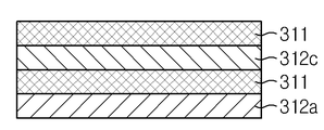
상기 단위셀(310uc)은 하나 이상의 음극과 양극이 분리막을 개재하여 적층된 것이다. 도 6a는 스택형 전지에 포함되는 단위셀의 단면을 예시적으로 도시한 것으로서, 도면 하단으로부터 차례로 음극(312a), 분리막(311), 양극(312c) 및 분리막(311)이 적층되어 있다. 스택형 전지를 제조하는 경우, 예를 들어 라미네이션 공정 효율을 높이기 위해 이와 같은 단위셀을 제조한 후 복수의 단위셀을 적층하여 소망하는 수준의 용량을 갖는 전지를 제조할 수 있다. 단위셀 내 전지 소자의 적층 순서나 개수, 복수의 단위셀의 적층 순서나 개수는 전지의 종류, 용량 및 용도 등에 따라 적절하게 조절할 수 있다. The unit cell 310uc is formed by stacking one or more cathodes and anodes with a separator interposed therebetween. 6A is a cross-sectional view of a unit cell included in a stacked type battery. The
도 5는 본 발명의 구체적인 일 실시양태에 따른 스택-폴딩형 전극 조립체(400)의 일 실시양태를 도시한 것이다. 이를 참조하면, 상기 전극 적층체는 둘 이상의 단위 셀들(410uc)이 절연성 분리 필름(430)을 개재하여 적층되어 있으며, 절연성 분리 필름(430)이 상기 전극 적층체의 외부를 감싸는 방식으로 준비된다. 또한, 고정 테이프(420)가 전극 조립체의 외부를 감싸는 방식으로 구비된다. Figure 5 illustrates one embodiment of a stack-
상기 단위셀(410uc)은 하나 이상의 음극과 양극이 분리막을 개재하여 적층된 것이다. 도 6b는 스택형 전지에 포함되는 단위셀의 단면을 예시적으로 도시한 것으로서, 도면 하단으로부터 차례로 음극(412a), 분리막(411) 및 양극(412c)이 적층되어 있다. 스택/폴딩형 전지를 제조하는 경우, 예를 들어 라미네이션 공정 효율을 높이기 위해 이와 같은 단위셀을 제조한 후 복수의 단위셀을 적층하여 소망하는 수준의 용량을 갖는 전지를 제조할 수 있다. 단위셀 내 전지 소자의 적층 순서나 개수, 복수의 단위셀의 적층 순서나 개수는 전지의 종류, 용량 및 용도 등에 따라 적절하게 조절할 수 있음은 본 기술분야에 속하는 당업자에게 자명하다. The unit cell 410uc is formed by stacking one or more cathodes and anodes with a separator interposed therebetween. 6B is a cross-sectional view of a unit cell included in the stacked type battery, in which a cathode 412a, a
본 발명에 있어서, 상기 절연성 분리 필름(330, 430)은 폴리올레핀 등 고분자 수지를 포함하는 다공성 수지 필름일 수 있다. 또는 상기 다공성 수지 필름의 적어도 일측 표면에 무기물 입자와 고분자 수지의 혼합물을 포함하는 내열층이 더 형성될 수 있다. In the present invention, the insulating
본원 발명에 있어서, 전기화학소자는 전기화학 에너지를 발생시킬 수 있는 전기화학소자이면 어느 것이나 가능하다. 이의 구체적인 예로써 모든 종류의 1차 전지, 이차 전지, 연료 전지, 태양 전지, 수퍼 캐패시터 소자와 같은 캐패시터 등이 있다. 특히 상기 이차 전지는 리튬 금속 이차 전지, 리튬 이온 이차 전지, 리튬 폴리머 이차 전지, 또는 리튬 이온 폴리머 이차 전지 등을 포함하는 리튬 이차 전지인 것이다. 바람직하게는 리튬 이온 이차 전지인 것이다. In the present invention, the electrochemical device may be any electrochemical device capable of generating electrochemical energy. Specific examples thereof include all kinds of primary cells, secondary cells, fuel cells, solar cells, capacitors such as super capacitor devices, and the like. Particularly, the secondary battery is a lithium secondary battery including a lithium metal secondary battery, a lithium ion secondary battery, a lithium polymer secondary battery, or a lithium ion polymer secondary battery. It is preferably a lithium ion secondary battery.
상기 리튬 이온 이차 전지에 있어서, 전극 적층체는 양극판 및 음극판이 세퍼레이터를 사이에 두고 배치된 형태로 구성된다. 또한, 전극 적층체는 다수의 양극판 및 다수의 음극판이 세퍼레이터를 사이에 두고 적층된 구조를 가질 수 있다. In the lithium ion secondary battery, the electrode stacked body is configured in such a manner that the positive electrode plate and the negative electrode plate are disposed with the separator interposed therebetween. Further, the electrode laminate may have a structure in which a plurality of positive electrode plates and a plurality of negative electrode plates are stacked with a separator interposed therebetween.
또한, 상기 전극 적층체는 양극판 및 음극판이 세퍼레이터를 사이에 두고 배치된 구조의 단위셀을 포함할 수 있다. 전극 적층체 및 단위셀의 구조에 대해서는 전술한 내용을 참조할 수 있다. In addition, the electrode stacked body may include a unit cell having a structure in which a positive electrode plate and a negative electrode plate are disposed with a separator interposed therebetween. The structure of the electrode laminate and the unit cell can be referred to the above description.
상기 양극판과 음극판은 각각 전극 집전체에 활물질 슬러리가 도포된 구조로서 형성될 수 있는데, 슬러리는 통상적으로 입상의 활물질, 보조도체, 바인더 및 가소제 등이 용매가 첨가된 상태에서 교반되어 형성될 수 있다.The positive electrode plate and the negative electrode plate may each be formed as a structure in which an active material slurry is applied to an electrode current collector. The slurry may be formed by agitating a granular active material, an auxiliary conductor, a binder, a plasticizer, .
한편, 상기 전극판은 슬러리가 도포되지 않은 무지부가 존재할 수 있으며, 이러한 무지부에는 각각의 전극판에 대응되는 전극 탭이 구비될 수 있다. 즉, 전극 적층체의 양극판에는 양극 탭이 부착되고, 음극판에는 음극 탭이 부착될 수 있다. 상기 양극 탭 및 음극 탭은 양극 리드 및 음극 리드에 전기적으로 연결되어, 전극 단자를 형성하며, 상기 전극 단자가 전지 외장재의 외부로 인출된다. Meanwhile, the electrode plate may have an uncoated portion to which the slurry is not applied, and the uncoated portion may include an electrode tab corresponding to each electrode plate. That is, a positive electrode tab may be attached to the positive electrode plate of the electrode stack, and a negative electrode tab may be attached to the negative electrode plate. The positive electrode tab and the negative electrode tab are electrically connected to the positive electrode lead and the negative electrode lead to form an electrode terminal, and the electrode terminal is drawn out to the outside of the battery casing.
또한, 본 발명은 상기 전극 조립체를 포함하는 파우치형 이차 전지를 제공한다. 상기 파우치형 이차 전지는 전지 내부에서 가스 발생 등 파우치 외형이 변화되더라도 내부의 전극 조립체는 형태 변형이 방지될 수 있다. 따라서, 전지 내부 소자의 변형에 의한 결함 발생 및 상기 결함에 따른 안전성 저하 문제가 방지될 수 있다. The present invention also provides a pouch-type secondary battery including the electrode assembly. In the pouch type secondary battery, even if the outer shape of the pouch is changed, such as generation of gas in the battery, deformation of the inner electrode assembly can be prevented. Accordingly, it is possible to prevent the occurrence of defects due to the deformation of the internal elements of the battery and the problem of lowering of safety due to the defects.
또한, 본 발명은 상기 파우치형 이차 전지를 둘 이상 포함하는 배터리 팩을 제공한다. 본 발명에 따른 배터리 팩은 이러한 이차 전지 이외에도, BMS(Battery Management System)와 같은 이차 전지의 충방전을 제어하기 위한 여러 보호 장치들을 더 포함할 수 있다.Also, the present invention provides a battery pack including at least two pouch type secondary batteries. The battery pack according to the present invention may further include various protection devices for controlling charge and discharge of a secondary battery such as a BMS (Battery Management System), in addition to the secondary battery.
이상과 같이, 본 발명은 비록 한정된 실시예와 도면에 의해 설명되었으나, 본 발명은 이것에 의해 한정되지 않으며 본 발명이 속하는 기술분야에서 통상의 지식을 가진 자에 의해 본 발명의 기술사상과 아래에 기재될 특허청구범위의 균등범위 내에서 다양한 수정 및 변형이 가능함은 물론이다.While the present invention has been particularly shown and described with reference to exemplary embodiments thereof, it is to be understood that the invention is not limited to the disclosed exemplary embodiments. It will be understood that various modifications and changes may be made without departing from the scope of the appended claims.
Claims (9)
An electrode assembly comprising an electrode assembly including a cathode, an anode, and a separator resumed between the cathode and the anode, and a fixation tape winding a plurality of external portions of the electrode assembly, And the fixing tape is provided to prevent or minimize deformation of the shape of the electrode stack body.
상기 고정 테이프는 폴리이미드(Polyimide)를 포함하는 것인, 전극 조립체.
The method according to claim 1,
Wherein the fixing tape comprises a polyimide.
상기 전극 적층체는 절연성 분리 필름을 더 포함하는 스택형(stack type) 또는 스택-폴딩형(stack and folding type)인 것이며, 상기 절연성 분리 필름은 전극 적층체의 적어도 일부를 감싸고 있는 것인, 전극 조립체.
The method according to claim 1,
Wherein the electrode laminate is a stack type or a stack and folding type further comprising an insulating separating film and the insulating separating film surrounds at least a part of the electrode laminate, Assembly.
상기 고정 테이프는 전극 조립체 두께의 1배 내지 4배의 간격으로 전극 조립체 외부를 감고 있는 것인, 전극 조립체.
The method according to claim 1,
Wherein the fixing tape is wound around the electrode assembly at an interval of one to four times the thickness of the electrode assembly.
상기 고정 테이프는 하나의 테이프가 연속적으로 다수회 전극 조립체 외부를 감고 있는 것인, 전극 조립체.
The method according to claim 1,
Wherein the fastening tape is one tape continuously wound around the outside of the electrode assembly a plurality of times.
상기 고정 테이프는 둘 이상의 다수의 테이프가 전극 조립체 외부를 각 1회 감고 있는 것인, 전극 조립체.
The method according to claim 1,
Wherein the fixed tape has two or more of the plurality of tapes wound around the outside of the electrode assembly once each time.
상기 전극 조립체에서 상기 고정 테이프에 의해 피복되는 면적은 전극 조립체 총 표면적 100% 대비 10% 내지 40%인 것인, 전극 조립체.
The method according to claim 1,
Wherein the area covered by the fixing tape in the electrode assembly is 10% to 40% of the total area of the electrode assembly.
상기 고정테이프는 기능성층 및 상기 기능성층의 일측표면에 형성된 점착층을 포함하며, 상기 기능성층은 폴리이미드를 포함하고, 상기 점착층은 점착성 물질을 포함하는 것인, 전극 조립체.
The method according to claim 1,
Wherein the fixing tape comprises a functional layer and an adhesive layer formed on one surface of the functional layer, the functional layer comprising polyimide, and the adhesive layer comprising a sticky material.
여기에서, 상기 전극 조립체는 제1항 내지 제8항 중 어느 한 항에 따른 것이고, 상기 파우치 외장재는 두 장의 절연성 고분자 필름 사이에 금속박막이 삽입된 적층 필름으로 구성되는 것인, 파우치형 전지.
A pouch type battery comprising an electrode assembly and a pouch exterior member accommodating the electrode assembly,
The pouch-type battery according to any one of claims 1 to 8, wherein the electrode assembly is composed of a laminated film in which a metal thin film is inserted between two sheets of insulating polymer films.
Priority Applications (1)
| Application Number | Priority Date | Filing Date | Title |
|---|---|---|---|
| KR1020160026464A KR102142673B1 (en) | 2016-03-04 | 2016-03-04 | A electrode assembly and a pouch type cell comprising the same |
Applications Claiming Priority (1)
| Application Number | Priority Date | Filing Date | Title |
|---|---|---|---|
| KR1020160026464A KR102142673B1 (en) | 2016-03-04 | 2016-03-04 | A electrode assembly and a pouch type cell comprising the same |
Publications (2)
| Publication Number | Publication Date |
|---|---|
| KR20170103485A true KR20170103485A (en) | 2017-09-13 |
| KR102142673B1 KR102142673B1 (en) | 2020-08-07 |
Family
ID=59967656
Family Applications (1)
| Application Number | Title | Priority Date | Filing Date |
|---|---|---|---|
| KR1020160026464A KR102142673B1 (en) | 2016-03-04 | 2016-03-04 | A electrode assembly and a pouch type cell comprising the same |
Country Status (1)
| Country | Link |
|---|---|
| KR (1) | KR102142673B1 (en) |
Cited By (2)
| Publication number | Priority date | Publication date | Assignee | Title |
|---|---|---|---|---|
| WO2020060022A1 (en) * | 2018-09-19 | 2020-03-26 | 주식회사 엘지화학 | Electrode assembly |
| WO2023063700A1 (en) * | 2021-10-12 | 2023-04-20 | 주식회사 엘지에너지솔루션 | Electrode assembly |
Citations (3)
| Publication number | Priority date | Publication date | Assignee | Title |
|---|---|---|---|---|
| KR20060092429A (en) * | 2005-02-17 | 2006-08-23 | 주식회사 엘지화학 | Stability-improved secondary battery containing fixing member |
| KR20080085316A (en) * | 2007-03-19 | 2008-09-24 | 삼성에스디아이 주식회사 | Rechargeable battery |
| KR20100131166A (en) * | 2009-06-05 | 2010-12-15 | 삼성에스디아이 주식회사 | Electrode assembly and secondary battery using the same |
-
2016
- 2016-03-04 KR KR1020160026464A patent/KR102142673B1/en active IP Right Grant
Patent Citations (3)
| Publication number | Priority date | Publication date | Assignee | Title |
|---|---|---|---|---|
| KR20060092429A (en) * | 2005-02-17 | 2006-08-23 | 주식회사 엘지화학 | Stability-improved secondary battery containing fixing member |
| KR20080085316A (en) * | 2007-03-19 | 2008-09-24 | 삼성에스디아이 주식회사 | Rechargeable battery |
| KR20100131166A (en) * | 2009-06-05 | 2010-12-15 | 삼성에스디아이 주식회사 | Electrode assembly and secondary battery using the same |
Cited By (3)
| Publication number | Priority date | Publication date | Assignee | Title |
|---|---|---|---|---|
| WO2020060022A1 (en) * | 2018-09-19 | 2020-03-26 | 주식회사 엘지화학 | Electrode assembly |
| US11545725B2 (en) | 2018-09-19 | 2023-01-03 | Lg Energy Solution, Ltd. | Electrode assembly |
| WO2023063700A1 (en) * | 2021-10-12 | 2023-04-20 | 주식회사 엘지에너지솔루션 | Electrode assembly |
Also Published As
| Publication number | Publication date |
|---|---|
| KR102142673B1 (en) | 2020-08-07 |
Similar Documents
| Publication | Publication Date | Title |
|---|---|---|
| US9077027B2 (en) | Electrode assembly and secondary battery using the same | |
| KR100309604B1 (en) | Lithium secondary battery | |
| KR101407772B1 (en) | Electorde assembly and secondary battery using the same | |
| KR101792572B1 (en) | Battery Cell Having Electrode Coated with Insulating Material | |
| KR102046056B1 (en) | A Battery cell Having Improved Cooling Performance | |
| KR20060096455A (en) | Lithium ion secondary battery | |
| US20200028200A1 (en) | Method for producing an electrode unit for a battery cell and electrode unit | |
| JP7221122B2 (en) | Battery cell electrode assembly manufacturing method and battery cell | |
| KR101994948B1 (en) | Stack and folding-type electrode assembly and method for fabricating the same | |
| KR20180058370A (en) | Electrode Assembly Comprising Separator Having Insulation-enhancing Part Formed on Edge Portion of Electrode | |
| KR20150043016A (en) | Electrode assembly and secondary battery comprising the same | |
| KR20160041225A (en) | Electrode Assembly Folded in the Bi-Direction and Lithium Secondary Battery Comprising the Same | |
| CN111656602B (en) | Secondary battery and apparatus including the same | |
| JP2005222884A (en) | Electrode lamination type battery | |
| KR20150050212A (en) | Battery cell with patterned shape and Method for manufacturing the same | |
| KR101558702B1 (en) | High-voltage battery for vehicle | |
| KR102142673B1 (en) | A electrode assembly and a pouch type cell comprising the same | |
| KR20150134660A (en) | Electrode Assembly and Composite Electrode Assembly of Stair-like Structure | |
| KR20190065138A (en) | Electrode and electrode-assembly | |
| WO2019103446A1 (en) | Electrode assembly having improved safety of use by means of exterior material pattern structure, and lithium-ion secondary battery having same | |
| KR20130131843A (en) | Novel electrode separator assembly for secondary battery and method manufacturing the same | |
| KR101650860B1 (en) | Battery Cell Having Separation Film of Suppressed Thermal Shrinkage | |
| KR20130085202A (en) | Secondary battery improved safety | |
| JP7098189B2 (en) | Secondary battery and battery module | |
| KR102421949B1 (en) | Electrode Assembly Comprising Electrode Mixture Layers Having Different Content Ratio of Binder |
Legal Events
| Date | Code | Title | Description |
|---|---|---|---|
| A201 | Request for examination | ||
| E902 | Notification of reason for refusal | ||
| E701 | Decision to grant or registration of patent right | ||
| GRNT | Written decision to grant |