KR20170101880A - Passively mode-locked fiber ring generator - Google Patents
Passively mode-locked fiber ring generator Download PDFInfo
- Publication number
- KR20170101880A KR20170101880A KR1020177003349A KR20177003349A KR20170101880A KR 20170101880 A KR20170101880 A KR 20170101880A KR 1020177003349 A KR1020177003349 A KR 1020177003349A KR 20177003349 A KR20177003349 A KR 20177003349A KR 20170101880 A KR20170101880 A KR 20170101880A
- Authority
- KR
- South Korea
- Prior art keywords
- pulse
- fiber
- signal
- ring cavity
- filter
- Prior art date
Links
Images


Classifications
-
- H—ELECTRICITY
- H01—ELECTRIC ELEMENTS
- H01S—DEVICES USING THE PROCESS OF LIGHT AMPLIFICATION BY STIMULATED EMISSION OF RADIATION [LASER] TO AMPLIFY OR GENERATE LIGHT; DEVICES USING STIMULATED EMISSION OF ELECTROMAGNETIC RADIATION IN WAVE RANGES OTHER THAN OPTICAL
- H01S3/00—Lasers, i.e. devices using stimulated emission of electromagnetic radiation in the infrared, visible or ultraviolet wave range
- H01S3/05—Construction or shape of optical resonators; Accommodation of active medium therein; Shape of active medium
- H01S3/06—Construction or shape of active medium
- H01S3/063—Waveguide lasers, i.e. whereby the dimensions of the waveguide are of the order of the light wavelength
- H01S3/067—Fibre lasers
- H01S3/06791—Fibre ring lasers
-
- H—ELECTRICITY
- H01—ELECTRIC ELEMENTS
- H01S—DEVICES USING THE PROCESS OF LIGHT AMPLIFICATION BY STIMULATED EMISSION OF RADIATION [LASER] TO AMPLIFY OR GENERATE LIGHT; DEVICES USING STIMULATED EMISSION OF ELECTROMAGNETIC RADIATION IN WAVE RANGES OTHER THAN OPTICAL
- H01S3/00—Lasers, i.e. devices using stimulated emission of electromagnetic radiation in the infrared, visible or ultraviolet wave range
- H01S3/10—Controlling the intensity, frequency, phase, polarisation or direction of the emitted radiation, e.g. switching, gating, modulating or demodulating
- H01S3/10007—Controlling the intensity, frequency, phase, polarisation or direction of the emitted radiation, e.g. switching, gating, modulating or demodulating in optical amplifiers
-
- H—ELECTRICITY
- H01—ELECTRIC ELEMENTS
- H01S—DEVICES USING THE PROCESS OF LIGHT AMPLIFICATION BY STIMULATED EMISSION OF RADIATION [LASER] TO AMPLIFY OR GENERATE LIGHT; DEVICES USING STIMULATED EMISSION OF ELECTROMAGNETIC RADIATION IN WAVE RANGES OTHER THAN OPTICAL
- H01S3/00—Lasers, i.e. devices using stimulated emission of electromagnetic radiation in the infrared, visible or ultraviolet wave range
- H01S3/05—Construction or shape of optical resonators; Accommodation of active medium therein; Shape of active medium
- H01S3/06—Construction or shape of active medium
- H01S3/063—Waveguide lasers, i.e. whereby the dimensions of the waveguide are of the order of the light wavelength
- H01S3/067—Fibre lasers
- H01S3/06708—Constructional details of the fibre, e.g. compositions, cross-section, shape or tapering
- H01S3/06725—Fibre characterized by a specific dispersion, e.g. for pulse shaping in soliton lasers or for dispersion compensating [DCF]
-
- H—ELECTRICITY
- H01—ELECTRIC ELEMENTS
- H01S—DEVICES USING THE PROCESS OF LIGHT AMPLIFICATION BY STIMULATED EMISSION OF RADIATION [LASER] TO AMPLIFY OR GENERATE LIGHT; DEVICES USING STIMULATED EMISSION OF ELECTROMAGNETIC RADIATION IN WAVE RANGES OTHER THAN OPTICAL
- H01S3/00—Lasers, i.e. devices using stimulated emission of electromagnetic radiation in the infrared, visible or ultraviolet wave range
- H01S3/05—Construction or shape of optical resonators; Accommodation of active medium therein; Shape of active medium
- H01S3/06—Construction or shape of active medium
- H01S3/063—Waveguide lasers, i.e. whereby the dimensions of the waveguide are of the order of the light wavelength
- H01S3/067—Fibre lasers
- H01S3/06754—Fibre amplifiers
-
- H—ELECTRICITY
- H01—ELECTRIC ELEMENTS
- H01S—DEVICES USING THE PROCESS OF LIGHT AMPLIFICATION BY STIMULATED EMISSION OF RADIATION [LASER] TO AMPLIFY OR GENERATE LIGHT; DEVICES USING STIMULATED EMISSION OF ELECTROMAGNETIC RADIATION IN WAVE RANGES OTHER THAN OPTICAL
- H01S3/00—Lasers, i.e. devices using stimulated emission of electromagnetic radiation in the infrared, visible or ultraviolet wave range
- H01S3/05—Construction or shape of optical resonators; Accommodation of active medium therein; Shape of active medium
- H01S3/08—Construction or shape of optical resonators or components thereof
- H01S3/08013—Resonator comprising a fibre, e.g. for modifying dispersion or repetition rate
-
- H—ELECTRICITY
- H01—ELECTRIC ELEMENTS
- H01S—DEVICES USING THE PROCESS OF LIGHT AMPLIFICATION BY STIMULATED EMISSION OF RADIATION [LASER] TO AMPLIFY OR GENERATE LIGHT; DEVICES USING STIMULATED EMISSION OF ELECTROMAGNETIC RADIATION IN WAVE RANGES OTHER THAN OPTICAL
- H01S3/00—Lasers, i.e. devices using stimulated emission of electromagnetic radiation in the infrared, visible or ultraviolet wave range
- H01S3/05—Construction or shape of optical resonators; Accommodation of active medium therein; Shape of active medium
- H01S3/08—Construction or shape of optical resonators or components thereof
- H01S3/08018—Mode suppression
- H01S3/08022—Longitudinal modes
- H01S3/08027—Longitudinal modes by a filter, e.g. a Fabry-Perot filter is used for wavelength setting
-
- H—ELECTRICITY
- H01—ELECTRIC ELEMENTS
- H01S—DEVICES USING THE PROCESS OF LIGHT AMPLIFICATION BY STIMULATED EMISSION OF RADIATION [LASER] TO AMPLIFY OR GENERATE LIGHT; DEVICES USING STIMULATED EMISSION OF ELECTROMAGNETIC RADIATION IN WAVE RANGES OTHER THAN OPTICAL
- H01S3/00—Lasers, i.e. devices using stimulated emission of electromagnetic radiation in the infrared, visible or ultraviolet wave range
- H01S3/09—Processes or apparatus for excitation, e.g. pumping
- H01S3/091—Processes or apparatus for excitation, e.g. pumping using optical pumping
- H01S3/094—Processes or apparatus for excitation, e.g. pumping using optical pumping by coherent light
- H01S3/094003—Processes or apparatus for excitation, e.g. pumping using optical pumping by coherent light the pumped medium being a fibre
-
- H—ELECTRICITY
- H01—ELECTRIC ELEMENTS
- H01S—DEVICES USING THE PROCESS OF LIGHT AMPLIFICATION BY STIMULATED EMISSION OF RADIATION [LASER] TO AMPLIFY OR GENERATE LIGHT; DEVICES USING STIMULATED EMISSION OF ELECTROMAGNETIC RADIATION IN WAVE RANGES OTHER THAN OPTICAL
- H01S3/00—Lasers, i.e. devices using stimulated emission of electromagnetic radiation in the infrared, visible or ultraviolet wave range
- H01S3/09—Processes or apparatus for excitation, e.g. pumping
- H01S3/091—Processes or apparatus for excitation, e.g. pumping using optical pumping
- H01S3/094—Processes or apparatus for excitation, e.g. pumping using optical pumping by coherent light
- H01S3/0941—Processes or apparatus for excitation, e.g. pumping using optical pumping by coherent light of a laser diode
-
- H—ELECTRICITY
- H01—ELECTRIC ELEMENTS
- H01S—DEVICES USING THE PROCESS OF LIGHT AMPLIFICATION BY STIMULATED EMISSION OF RADIATION [LASER] TO AMPLIFY OR GENERATE LIGHT; DEVICES USING STIMULATED EMISSION OF ELECTROMAGNETIC RADIATION IN WAVE RANGES OTHER THAN OPTICAL
- H01S3/00—Lasers, i.e. devices using stimulated emission of electromagnetic radiation in the infrared, visible or ultraviolet wave range
- H01S3/10—Controlling the intensity, frequency, phase, polarisation or direction of the emitted radiation, e.g. switching, gating, modulating or demodulating
- H01S3/10007—Controlling the intensity, frequency, phase, polarisation or direction of the emitted radiation, e.g. switching, gating, modulating or demodulating in optical amplifiers
- H01S3/10023—Controlling the intensity, frequency, phase, polarisation or direction of the emitted radiation, e.g. switching, gating, modulating or demodulating in optical amplifiers by functional association of additional optical elements, e.g. filters, gratings, reflectors
-
- H—ELECTRICITY
- H01—ELECTRIC ELEMENTS
- H01S—DEVICES USING THE PROCESS OF LIGHT AMPLIFICATION BY STIMULATED EMISSION OF RADIATION [LASER] TO AMPLIFY OR GENERATE LIGHT; DEVICES USING STIMULATED EMISSION OF ELECTROMAGNETIC RADIATION IN WAVE RANGES OTHER THAN OPTICAL
- H01S3/00—Lasers, i.e. devices using stimulated emission of electromagnetic radiation in the infrared, visible or ultraviolet wave range
- H01S3/10—Controlling the intensity, frequency, phase, polarisation or direction of the emitted radiation, e.g. switching, gating, modulating or demodulating
- H01S3/11—Mode locking; Q-switching; Other giant-pulse techniques, e.g. cavity dumping
- H01S3/1106—Mode locking
- H01S3/1112—Passive mode locking
-
- H—ELECTRICITY
- H01—ELECTRIC ELEMENTS
- H01S—DEVICES USING THE PROCESS OF LIGHT AMPLIFICATION BY STIMULATED EMISSION OF RADIATION [LASER] TO AMPLIFY OR GENERATE LIGHT; DEVICES USING STIMULATED EMISSION OF ELECTROMAGNETIC RADIATION IN WAVE RANGES OTHER THAN OPTICAL
- H01S3/00—Lasers, i.e. devices using stimulated emission of electromagnetic radiation in the infrared, visible or ultraviolet wave range
- H01S3/10—Controlling the intensity, frequency, phase, polarisation or direction of the emitted radiation, e.g. switching, gating, modulating or demodulating
- H01S3/13—Stabilisation of laser output parameters, e.g. frequency or amplitude
- H01S3/131—Stabilisation of laser output parameters, e.g. frequency or amplitude by controlling the active medium, e.g. by controlling the processes or apparatus for excitation
- H01S3/1312—Stabilisation of laser output parameters, e.g. frequency or amplitude by controlling the active medium, e.g. by controlling the processes or apparatus for excitation by controlling the optical pumping
-
- H—ELECTRICITY
- H01—ELECTRIC ELEMENTS
- H01S—DEVICES USING THE PROCESS OF LIGHT AMPLIFICATION BY STIMULATED EMISSION OF RADIATION [LASER] TO AMPLIFY OR GENERATE LIGHT; DEVICES USING STIMULATED EMISSION OF ELECTROMAGNETIC RADIATION IN WAVE RANGES OTHER THAN OPTICAL
- H01S3/00—Lasers, i.e. devices using stimulated emission of electromagnetic radiation in the infrared, visible or ultraviolet wave range
- H01S3/10—Controlling the intensity, frequency, phase, polarisation or direction of the emitted radiation, e.g. switching, gating, modulating or demodulating
- H01S3/13—Stabilisation of laser output parameters, e.g. frequency or amplitude
- H01S3/136—Stabilisation of laser output parameters, e.g. frequency or amplitude by controlling devices placed within the cavity
Abstract
펄스 섬유 발생기는 펄스 트레인을 방출하도록 구성된 단방향 링 도파관으로 구성된다. 링 도파관은 다수의 섬유 증폭기, 제1 및 제2 섬유 증폭기의 각각의 출력에 결합된 처프 섬유 구성 요소, 및 처프 성분의 각각의 출력에 결합된 다수의 스펙트럼 필터를 포함한다. 필터는 링 공동에 유도된 비선형 프로세스에 응답하여 링 공동을 따라 빛의 누설을 제공하기 위해 서로 다른 중심 파장 주위에 센터링된 각각의 스펙트럼 통과 대역을 갖는다. 펄스 발생기는 예비 단계에서 피치를 신호로 발현시키도록 작동하며, 정상 단계에서, 신호의 단일 왕복당 최대 한번 펄스 트레인을 출력 커플러를 통해 출력하도록 작동한다.The pulse fiber generator consists of a unidirectional ring waveguide configured to emit a pulse train. The ring waveguide includes a plurality of fiber amplifiers, a chirped fiber component coupled to respective outputs of the first and second fiber amplifiers, and a plurality of spectral filters coupled to respective outputs of the chirp components. The filter has respective spectral passbands centered around different center wavelengths to provide leakage of light along the ring cavity in response to a nonlinear process induced in the ring cavity. The pulse generator is operative to generate a signal as a signal in the preliminary step and operates to output through the output coupler at most one pulse train per single round trip of the signal in the normal phase.
Description
본 발명은 단 펄스 섬유 링 레이저 시스템에 관한 것이다. 특히, 본 발명은 서브 나노초 거대 처프 펄스(giant-chirped pulse)를 생성하도록 구성된 수동적으로 모드 잠금된 섬유 링 공동에 관한 것이다. The present invention relates to a short-pulse fiber ring laser system. More particularly, the present invention relates to passively mode-locked fiber ring cavities configured to generate sub-nanosecond giant-chirped pulses.
용어 해설Glossary of terms
재료의 이상 분산은 점진적으로 증가하는 파장에 따라 굴절률이 증가하는 재료를 의미한다. The anomalous dispersion of a material means a material whose refractive index increases with a gradually increasing wavelength.
대역폭은 입사 에너지를 통과하는 스펙트럼의 특정 부분을 나타내기 위해 사용되는 파장 범위이다. The bandwidth is the wavelength range used to represent a specific part of the spectrum passing through the incident energy.
차단 범위는 필터에 의해 감쇄되는 에너지의 스펙트럼 영역을 나타내기 위해 사용되는 파장 간격이다. The blocking range is the wavelength spacing used to represent the spectral range of the energy attenuated by the filter.
중심 파장(CWL)은 장단 파장 기울기에서의 최대 진폭의 절반 사이의 중간 지점이다. The center wavelength (CWL) is the midpoint between half of the maximum amplitude at the long and short wavelength slopes.
처프 펄스는 시간 영역에서 펄스를 가로질러 순간 중심 파장(주파수)이 변하는 펄스를 의미한다. The chirped pulse means a pulse whose instantaneous center wavelength (frequency) changes across the pulse in the time domain.
원하는 펄스는 링 공동에서 생성된 원하는 스펙트럼 폭과 지속 시간을 갖는 펄스이다. The desired pulse is a pulse with the desired spectral width and duration generated in the ring cavity.
분산은 주파수에 대한 재료 내에서의 광 전파 속도(또는 굴절률)의 의존성을 의미한다. Dispersion refers to the dependence of the light propagation velocity (or refractive index) on the material with respect to frequency.
아이솔레이터(isolator)는 한 방향으로만 빛을 투과시키는 장치를 의미한다. An isolator is a device that transmits light in one direction only.
선형성은, 상식적으로, 서로 정비례하는 2개의 수량에서와 같이, 그래프에서 직선으로 표현될 수 있는 수학적 관계를 의미한다. Linearity refers to a mathematical relationship that can be expressed in straight lines in a graph, such as in two quantities that are directly proportional to each other.
선형 주파수 처프는 시간 영역에서 펄스를 가로질러 주파수가 선형적으로 변하는 펄스를 의미한다. Linear frequency chirp means a pulse whose frequency varies linearly across the pulse in the time domain.
비선형성은 인가된 전자기장에 대한 재료의 반응이 이 전자기장의 진폭에서 비선형적인 체제에서의 물질과 빛의 상호 작용이다. Nonlinearity is the interaction of matter with light in a nonlinear regime in the amplitude of the electromagnetic field of the material response to the applied electromagnetic field.
비선형 위상 획득은 전기장의 진폭에 따른 위상의 비선형 이득을 의미하며; 비선형 위상 획득의 징후 중 하나는 자기 위상 변조 비선형 현상으로 인한 광 펄스의 스펙트럼 성분의 확대이다. Nonlinear phase acquisition refers to the nonlinear gain of the phase with amplitude of the electric field; One of the signs of nonlinear phase acquisition is the magnification of the spectral components of the optical pulses due to self phase modulation nonlinear phenomena.
재료의 정상(양의) 분산은 점진적으로 증가하는 파장에 따라 굴절률이 감소하는 재료를 의미한다. The normal (positive) dispersion of the material means a material whose refractive index decreases with increasingly increasing wavelengths.
광학 필터는 특정 파장 범위 내의 빛을 선택적으로 투과시키면서 나머지를 차단하도록 구성된다. 이들은 일반적으로 장 파장 전용(롱패스) 필터, 단 파장 전용(숏패스) 필터를 통과할 수 있다. The optical filter is configured to selectively transmit light within a specific wavelength range while blocking the rest. They can generally pass through a long-wavelength (long-pass) filter or a short-wavelength (short-pass) filter.
광학 경로는 기하학적 경로와 굴절률의 곱이다. The optical path is the product of the geometric path and the refractive index.
발진기의 주기성(경계) 조건은 링 공동을 각각 1회 통과한 이후의 펄스 매개 변수의 반복성이다. The periodic (boundary) condition of the oscillator is the repeatability of the pulse parameters after each pass through the ring cavity once.
위상은 원점에 대해 경과한 파동 사이클의 일부이다. The phase is part of the wave cycle that has elapsed with respect to the origin.
위상 변이는 일렬로 정렬되지 않은 2개의 다중 파동을 의미한다. 위상 변이는 각각의 동일한 파동들의 광학 경로에서의 차이에 기인할 수 있다. Phase shifts mean two multiple waves not aligned in a row. The phase shift may be due to a difference in the optical path of each of the same waves.
피치는 하나의 왕복(round trip)에서 다른 왕복까지 링 공동의 임의의 주어진 지점에서 서로 다른 특성을 갖는 초기에 링 공동을 따라 안내되는 빛에서 발현되는 펄스를 의미한다.Pitch refers to a pulse that is expressed in light guided along a ring cavity initially with different properties at any given point in the ring cavity from one round trip to another round trip.
펄스 지속 시간(τP)은 파워가 피크 파워의 적어도 절반이 되는 시간 간격의 폭이다(FWHM). 초단 펄스는 피코초-펩토초 펄스 지속 시간 범위 내의 펄스이다.The pulse duration ([tau] P ) is the width of the time interval at which the power is at least half of the peak power (FWHM). The shortest pulse is a pulse within the picosecond-peptotec pulse duration range.
펄스 에너지는 피크 파워와 펄스 폭의 곱이며(이는 정사각형 펄스 근사에서는 맞지만, 본 출원인은 NALM의 성능을 설명하기 위해 순간 강도가 더 높은 펄스의 일부에 대해 아래에서 논의하고 있기 때문에, 본 출원인은 이를 "시간적 펄스 강도 곡선 아래의 면적"으로 고쳐 말해야 한다), 본질적으로는, 펄스 내부의 면적이다.Because the pulse energy is the product of the peak power and the pulse width (which is true for the square pulse approximation, but Applicants have been discussing below for some of the higher instantaneous pulses to account for the performance of the NALM, Quot; area under the temporal pulse intensity curve "), which is essentially the area inside the pulse.
Q-인자는 일반적으로 왕복당 소모된 에너지에 대한 저장된 에너지의 비율이다.The Q-factor is generally the ratio of the stored energy to the energy consumed per round trip.
스펙트럼 영역은 순간 주파수가 일정한 펄스(즉, 처프가 없는 펄스)에서도 유한한 스펙트럼 폭(대역폭)을 설명하는 광 펄스의 특성이다.The spectral range is a characteristic of a light pulse that describes a finite spectral width (bandwidth) even in a pulse with a constant instantaneous frequency (i.e., a chirped pulse).
자기 위상 변조(SPM)는 광 펄스의 강도에 대한 매질의 굴절률의 의존성에 기인한 현상이며, 광 펄스의 확장을 포함하여 스펙트럼 및 시간적 변조에 의해 발현된다.The self phase modulation (SPM) is a phenomenon due to the dependence of the refractive index of the medium on the intensity of the optical pulse, and is expressed by spectral and temporal modulation including expansion of the optical pulse.
자기 유사 펄스("시밀라리톤(similariton)")는 비선형 프로세스에서 획득한 위상을 선형 주파수 처프로 변환할 수 있는 포물선 펄스를 의미한다.A self-similar pulse ("similiton") refers to a parabolic pulse that can transform a phase acquired in a nonlinear process to a linear frequency.
신호는 1회 왕복 동안 연속적으로 매개 변수를 변화시키지만, 후속 왕복 동안 링 공동의 임의의 주어진 지점에서 동일한 특성을 갖는 것을 특징으로 하는, 피치로부터 발현된 빛의 펄스를 의미한다.The signal means a pulse of light emerging from a pitch, which continuously changes the parameter during a round trip, but has the same characteristics at any given point in the ring cavity during subsequent round trips.
단 펄스는 서브 나노초 범위의 지속 시간을 갖는 펄스를 의미한다.The short pulse means a pulse having a duration in the sub nanosecond range.
솔리톤은 링 공동 전체에서 전파하는 동안 그 시간적 및 스펙트럼 형상을 보존하는 처프 펄스를 의미한다.A soliton means a chirp pulse that preserves its temporal and spectral shape during propagation throughout the ring cavity.
시간적 영역은 광 파워(P)에 관련된 광 펄스의 특성, 즉, 짧은 시간 간격 내에서만 감지할 수 있으며 모든 다른 시간에서는 제로에 가까운 단위 시간당 에너지이다.The temporal region is the characteristic of the light pulse associated with the optical power P, i.e., the energy per unit time which is detectable only within a short time interval and near zero at all other times.
과도 펄스는 원하는 펄스와는 다른 스펙트럼 폭과 지속 시간을 갖는(이는 특히 적시에 더 작거나 더 클 수 있다), 링 공동 주위에서 안내되도록 발현되는 펄스이다.A transient pulse is a pulse that is guided around the ring cavity with a different spectral width and duration than the desired pulse (which can be less or less timely in particular).
높은 펄스 주파수 반복률과 조합되어 높은 펄스 피크 강도와 혁신적인 아키텍처를 제공하는 단 펄스 섬유 레이저 시스템은 전례 없는 품질, 정확성 및 속도를 갖는 구성 요소를 제조하는데 도움을 준다. 펄스의 짧은 지속 시간으로 인해, 열이 증착될 수 있는 것보다 짧은 시간에 레이저 에너지가 재료에 입력될 수 있으며, 이에 따라 부품에 대한 열 손상을 방지한다. 당연히, 산업용 서브 나노초 레이저 시스템은 의료 기기 시장에서부터 많은 다른 주요 산업에 이르기까지 광범위하게 응용될 수 있다.Combined with high pulse frequency repetition rates, providing a high pulse peak intensity and an innovative architecture, a single pulse fiber laser system helps manufacture components with unprecedented quality, accuracy and speed. Due to the short duration of the pulse, laser energy can be input to the material in a shorter time than heat can be deposited, thereby preventing thermal damage to the part. Naturally, the industrial sub-nanosecond laser system can be widely used from the medical device market to many other major industries.
펄스 레이저 시스템은 반드시 레이저 공동을 갖는 펄스 발생기 또는 발진기로 구성된다. 공동 내에서 순환하며 손실보다 많은 이득을 갖는 주파수를 세로 모드(longitudinal mode)라 하며, 독립된 발진기들의 조립체로서 간주될 수 있다. 공동 내에서 순환하는 동안, 세로 모드들은 여기서 특히 관심이 가는 링 공동으로 구성된 섬유 레이저의 경우 ΔF = v/L에 의해 분리되며, 여기서, L은 공동의 길이이고, v는 빛의 속도이다. 이 모드들은 서로 독립적으로 발진하며, 레이저는 계속 방출한다. 그러나, 다양한 모드들 간에 고정된 위상 변이가 존재하는 경우에는, 공동은 펄스 열을 방출하고, 모드 잠금된다.Pulsed laser systems consist essentially of a pulse generator or oscillator with a laser cavity. Frequencies that circulate in the cavity and have more gain than losses are referred to as longitudinal modes and can be viewed as an assembly of discrete oscillators. During circulation in the cavity, the longitudinal modes are separated here by ΔF = v / L, where L is the length of the cavity and v is the velocity of the light, for a fiber laser, which is composed of ring cavities of particular interest here. These modes oscillate independently of one another and the laser continues to emit. However, if there is a fixed phase shift between the various modes, the cavity emits a pulse train and is mode locked.
초단 펄스를 발생시키는 여러 방법이 공지되어 있다. 이러한 방법 중 하나인 수동 모드 잠금이 개시된 요지의 일부이다. 수동 모드 잠금의 단서는 증가하는 피크 강도에 대해 비선형 응답을 갖는 적어도 하나의 구성 요소의 링 공동 내에서의 존재이다. 수동 모드 잠금 방법을 실시하는 여러 아키텍처가 공지되어 있다.Various methods of generating short pulse are known. One such method is part of the subject matter in which the passive mode locking is disclosed. The cue of passive mode locking is the presence in the ring cavity of at least one component with a nonlinear response to increasing peak intensity. Several architectures are known that implement the passive mode locking scheme.
이러한 아키텍처 중 하나는 도 1에 도시된 링 공동을 이용하여 가장 잘 알 수 있는 비선형 편광 회전(NLPR)이다. 2개의 편광 제어기 사이에 배치된 편광 아이솔레이터는 모드 잠금 요소로서 작용한다. 이는 아이솔레이터를 떠나는 빛이 선형적으로 편광되도록 아이솔레이터와 편광기의 이중 역할을 수행한다. 아이솔레이터 다음에 배치된 편광 제어기는 편광 상태를 타원형으로 변화시킨다. 편광 상태는 직교하여 편광되는 구성 요소들에 부과되는 자기 위상 및 교차 위상 유도 위상 변이 때문에 펄스의 전파 중에 비선형적으로 전개한다. 편광의 상태는 비선형 위상 변이의 강도 의존성 때문에 펄스를 가로질러 불균일하다. (아이솔레이터 앞에 있는) 제2 편광 제어기는 펄스의 중심부에서 편광을 선형화하도록 조정된다. 편광 아이솔레이터는 펄스 중앙의 강한 부분은 통과시키지만, 저 강도의 펄스 윙은 차단(흡수)한다. 최종 결과, 펄스는 링 공동 내부를 1회 왕복한 후 단축된다. 따라서, 복굴절 섬유와 함께 공조하는 편광 의존형 아이솔레이터는 강도 의존 손실을 발생시킬 수 있다.One such architecture is nonlinear polarization rotation (NLPR), which is best known using the ring cavity shown in FIG. The polarization isolator disposed between the two polarization controllers acts as a mode locking element. This serves dual roles as an isolator and a polarizer so that the light leaving the isolator is linearly polarized. The polarization controller disposed after the isolator changes the polarization state to an elliptical shape. The polarization state develops non-linearly during the propagation of the pulse due to the magnetic phase and cross-phase induced phase shift imposed on orthogonally polarized components. The state of polarization is non-uniform across the pulse due to the intensity dependence of the non-linear phase shift. A second polarization controller (before the isolator) is adjusted to linearize the polarization at the center of the pulse. The polarizing isolator passes the strong part of the pulse center but blocks (absorbs) the low intensity pulse wing. As a final result, the pulse is shortened after one round of inside the ring cavity. Thus, a polarization dependent isolator that cooperates with a birefringent fiber can cause intensity dependent loss.
솔리톤, 전적으로 정상적인 공동 분산을 일반적으로 갖는 이득 안내 솔리톤 및 시밀라리톤을 포함한 NLPR 아키텍처를 사용하여, 다양한 초고 에너지 펄스가 성공적으로 발생될 수 있다. 그러나, 편광 제어기는 미세 제어 시스템에 의한 복잡한 피드백을 필요로 한다. NLPR 프로세스는 환경 변화 및 패키징 조건에 민감하다. 그 결과, 주기성 조건, 즉, 레이저 공동의 각각의 왕복 후에 일정한 위치에서의 펄스 특성의 재현성을 만족시키기 어렵다.Using a soliton, an NLPR architecture including a gain guided soliton and a similariton, which generally have an entirely normal cavity dispersion, a variety of ultra-high energy pulses can be successfully generated. However, the polarization controller requires complicated feedback by a fine control system. The NLPR process is sensitive to environmental changes and packaging conditions. As a result, it is difficult to satisfy the periodicity condition, that is, the reproducibility of the pulse characteristic at a constant position after each round trip of the laser cavity.
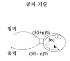
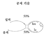
간섭계형 섬유 아키텍처는 2개의 일반적인 유형, 즉, 도 2a에 도시된 비선형 광학 루프 미러(NOLM)와 도 2b에 나타낸 비선형 증폭 루프 미러(NALM)를 갖는다. 이 장치들은 모두 사냑(Sagnac) 간섭계의 작동에 따라 동작한다. 후자는 루프를 형성하도록 출력 포트들이 함께 결합된 용융 섬유 커플러로 구성되며, 50%로 균등하게 분할하지 않는 커플러에 의해(NOLM), 또는 커플러의 포트 중 하나에 더 가깝게 인-라인 섬유 증폭기를 포함시킴으로써(NALM), 역 전파 강도(Ic(시계 방향), Icc(반시계 방향))들이 달라진다.The interferometric fiber architecture has two general types, namely the nonlinear optical loop mirror (NOLM) shown in FIG. 2A and the nonlinear amplification loop mirror (NALM) shown in FIG. 2B. All of these devices operate according to the operation of the Sagnac interferometer. The latter consists of a molten fiber coupler with the output ports coupled together to form a loop, either by a coupler (NOLM) that does not evenly divide by 50%, or an in-line fiber amplifier closer to one of the ports of the coupler (NALM), the back-propagation intensity (Ic (clockwise), Icc (counterclockwise)) are different.
불균등한 강도를 갖는 광학 레플리카는 비선형 굴절률로 인해 차동 위상 변이를 취득한다. 예컨대, 도 2a에서, 커플러는 강도(Icc)를 갖는 반시계 방향으로 전파하는 레플리카에서 반송되는 (50-n)%(Icc)와 시계 방향 레플리카에서 반송되는 (50+n)%(Ic) 사이에서 신호의 광 강도를 분할한다. 따라서, 시계 방향 레플리카의 Ic가 섬유의 비선형 응답을 유발하기에, 즉, SPM을 유도하기에 충분히 강하고, 다른 레플리카의 Icc가 낮으면, 서로 다른 순간 강도를 갖는 역전파 레플리카들의 부품들 사이에 상당한 차동 위상 변이가 축적될 것이다. 용융 커플러를 통해 전파하며, 레플리카들은 서로 간섭한다. 고강도 펄스 팁에 대응하는 비-매칭 위상을 얻는 레플리카의 일부만이 루프를 통해 전파하는 동안 SPM 프로세스의 결과로서 구조적으로 간섭하여, 공지된 NALM을 형성한다.Optical replicas with unequal intensity acquire differential phase shift due to nonlinear refractive index. For example, in FIG. 2A, the coupler is arranged between (50-n)% (Icc) conveyed in a counterclockwise propagating replica having an intensity Icc and (50 + n)% (Ic) conveyed in a clockwise replica The light intensity of the signal is divided. Thus, if the Ic of the clockwise replica is strong enough to induce a nonlinear response of the fiber, i. E., To induce the SPM, and the Icc of the other replica is low, Differential phase shifts will accumulate. Propagate through the melt coupler, and the replicas interfere with each other. Only a portion of the replicas that obtain a non-matching phase corresponding to the high intensity pulse tip will interfere structurally as a result of the SPM process during propagation through the loop, forming the known NALM.
간섭계형 모드 잠금 아키텍처에 따라 구성된 레이저는 이 특별한 접근법의 실용적인 장점 또는 단점에 대한 논의를 상당히 어렵게 만드는 비교적 새롭고 거의 사용되지 않은 구조를 나타낸다. 그러나, NLPR과 마찬가지로, NOLM/NALM 아키텍처는 원하는 안정성을 갖지 않을 수 있으며, 즉, 출력 펄스가 균일하지 않을 수 있다. 펄스 불균일성은 불량한 레이저 성능으로 이어진다. 또한, NLPR과 마찬가지로, NOLM/NALM 아키텍처는 간단하지도 않고, 특히 경제적이지도 않다.Lasers constructed in accordance with an interferometric mode lock architecture exhibit a relatively new and almost unused structure that makes it difficult to discuss the practical advantages or disadvantages of this particular approach. However, like NLPR, the NOLM / NALM architecture may not have the desired stability, i.e., the output pulses may not be uniform. Pulse non-uniformity leads to poor laser performance. Also, like the NLPR, the NOLM / NALM architecture is neither simple nor economical.
따라서, 균일하고 고 에너지의 서브 나노초 광 펄스를 출력할 수 있는 간단하고 견고한 구조를 갖는 링 공동 펄스 발생기에서 수동 모드 잠금을 실시하도록 작동하는 완전히 새로운 아키텍처에 대한 수요가 존재한다.Thus, there is a need for a completely new architecture that operates to implement passive mode locking in a ring cavity pulse generator with a simple and robust structure that can output uniform, high energy sub-nanosecond light pulses.
처프 펄스를 발생시키도록 설계된 모든 공지된 아키텍처와 대조적으로, 개시된 링 공동은 비선형 응답을 갖는 단일의 개별 요소가 없다. 즉, 펄스가 각각의 개별 요소를 통해 전파할 때, 스펙트럼 성분의 강도가 선형적으로만 변한다.In contrast to all known architectures designed to generate chirped pulses, the disclosed ring cavity lacks a single discrete element with a nonlinear response. That is, as the pulse propagates through each individual element, the intensity of the spectral component changes only linearly.
본 발명의 구조에서의 비선형 효과는 링 공동 내부에서 펄스가 전개되는 동안 새로운 스펙트럼 성분이 발생한 결과이다. 서로 다른 중심 파장에 센터링되고 피크 강도가 비선형적으로 변하는 2개의 스펙트럼 필터를 펄스가 통과하도록 하는 것은 이 새로운 스펙트럼 성분이다. 새로운 스펙트럼 성분은, CW 및 Q 스위칭과 마찬가지로, 다른 유형의 발생에 비해 모드 잠금의 낮은 손실로 인해, 모드 동기화 프로세스를 매우 경쟁력 있게 만든다.The nonlinear effect in the structure of the present invention is the result of a new spectral component occurring during the development of a pulse inside the ring cavity. It is this new spectral component that allows the pulse to pass through two spectral filters centered at different center wavelengths and whose peak intensity varies nonlinearly. The new spectral components, like CW and Q switching, make the mode synchronization process very competitive, due to the low loss of mode lock over other types of occurrences.
본 발명의 구조는 솔리톤, 시밀라리톤 등을 포함하는 다양한 유형의 펄스를 발생시킬 수 있으며, 거대 처프를 갖는 초단 펄스의 발생에 특히 유리하다. 거대 처프 펄스 발생의 경우, 단 펄스 발생기의 수동 모드 잠금 체제를 확립하기 위한 2개의 단계, 즉, (a) 넓은 펄스로부터 스펙트럼이 좁은 펄스를 필터링하는 단계와, (b) 장 섬유에서 빛에 영향을 미치는 비선형 효과로 인해 주파수 영역과 시간 영역 모두에서 형성된 좁은 펄스를 확장시키는 단계가 중요하다. 이 2개의 단계의 결과가 도 3의 양으로 처프된 선형 펄스이며, 즉, 최초의 펄스에 비해 스펙트럼 영역과 시간적 영역 모두에서 확장되고 펄스를 가로질러 반송 주파수가 선형적으로 변하는 펄스이다. 반송 주파수의 선형성은 이와 같이 신장된 펄스의 추가 압축에 중요하다.The structure of the present invention is capable of generating various types of pulses, including solitons, mimarriths, and the like, and is particularly advantageous for the generation of ultra-short pulses with large chirps. In the case of a giant chirped pulse generation, there are two steps for establishing a passive mode locking scheme of the short pulse generator: (a) filtering the narrow spectrum pulse from a broad pulse; (b) It is important to extend the narrow pulse formed in both the frequency domain and the time domain. The result of these two steps is a linear pulse chirped in Fig. 3, that is, a pulse that extends both in the spectral and temporal regions relative to the first pulse and linearly changes the carrier frequency across the pulse. The linearity of the carrier frequency is important for this further compression of the elongated pulse.
처프 펄스를 출력하는 이유는 레이저 기술 분야의 기술자에게 공지되어 있으며, 레이저(및 증폭기)로부터 이용 가능한 펄스 피크 강도를 다소 감소시켜야 하는데, 그렇지 않으면, 유해한 비선형 효과와 광학 손상이 펄스 발생기(및 증폭기)의 작동을 약화시키기 때문이다. 펄스 지속 시간 또는 처핑을 확장하고, 피크 파워를 안전한 수준으로 유지한 다음, 후속하는 하나 또는 다수의 증폭 단계 후에 원래의 지속 시간으로 출력 펄스를 압축함으로써, 이 문제에 대한 해결책이 밝혀졌다.The reason for outputting chirp pulses is known to those skilled in the art of laser technology and requires a somewhat reduced pulse peak intensity available from the laser (and amplifier), otherwise harmful nonlinear effects and optical impairments may occur in the pulse generator (and amplifier) As shown in FIG. A solution to this problem has been found by extending the pulse duration or chirping, keeping the peak power at a safe level, and then compressing the output pulse to its original duration after one or more subsequent amplification steps.
본 발명의 거대 처프 펄스 발생기는 한 방향으로 빛을 안내하는 링 섬유 도파관 또는 공동으로 구성된다. 섬유 도파관은 링 섬유 도파관 내에 링 전파의 원하는 방향성을 제공하는 섬유 아이솔레이터를 포함한다. 링 섬유 도파관을 구성하는 복수의 모든 섬유 구성 요소는 다수의 섬유 체인으로 조직되며, 각각의 섬유 체인은 하나의 증폭기, 하나의 섬유 코일 및 하나의 스펙트럼 필터를 반드시 포함한다. 본 발명의 펄스 발생기의 기동 단계에서, 외부의 시드 소스로부터 발사된 에탈론 펄스 또는 펌프에 의해 인공적으로 유도된 잡음에 응답하여, 연속파(CW) 성분 또는 피치 성분(들)을 특징으로 하는 원하는 스펙트럼 범위 내에서 제1 섬유 증폭기에서 자연 방출이 증폭된다(ASE). 제1 섬유 코일을 통해 전파하면서, 피치는 다소 스펙트럼적으로 그리고 시간적으로 확장되며, 제1 필터에서 더 스펙트럼적으로 필터링된다. 예컨대, 피치의 장 파장 서브 영역이 원하는 방향으로 더 전파하지 못하도록 필터링된다.The giant chirped pulse generator of the present invention consists of a ring fiber waveguide or cavity that guides light in one direction. The fiber waveguide includes a fiber isolator that provides a desired directionality of the ring wave within the ring fiber waveguide. All of the plurality of fiber components constituting the ring fiber waveguide are organized into a plurality of fiber chains, and each fiber chain necessarily includes one amplifier, one fiber coil and one spectral filter. In the start-up phase of the pulse generator of the present invention, in response to artificially induced noise generated by an etalon pulse or pump emitted from an external seed source, the desired spectrum (s) characterized by a continuous wave (CW) component or a pitch component Spontaneous emission is amplified in the first fiber amplifier within the range (ASE). As it propagates through the first fiber coil, the pitch extends somewhat spectrally and temporally, and is more spectrally filtered in the first filter. For example, the long wavelength sub-region of the pitch is filtered to prevent further propagation in the desired direction.
필터링된 펄스 성분은 제2 섬유 코일을 통해 전파하면서 자기 위상 변조(SPM) 비선형 효과를 유도하기에 충분한 피크 강도로 제2 증폭기에서 더 증폭된다. SPM은 중심 성분 주위에서 새로운 주파수 성분 또는 모드의 발생에 의해 나타나는 펄스 성분의 스펙트럼 및 시간 확장에 의해 나타난다. 새로 발생된 주파수 성분 중 일부는 제1 필터와는 대조적으로 피치의 단 파장 서브 영역을 차단하는 제2 필터의 주파수 통과 대역에 부분적으로 중첩한다. 새로운 스펙트럼 성분의 발생은 피치, 즉, 자기 위상 변조 현상을 유도하기에 충분한 동기화된 모드를 갖는 피치의 특정 피크 강도에서만 가능하게 된다.The filtered pulse component is further amplified in the second amplifier with sufficient peak intensity to propagate through the second fiber coil to induce a self phase modulation (SPM) nonlinear effect. The SPM is represented by a new frequency component around the central component or by the spectrum and time extension of the pulse component represented by the generation of the mode. Some of the newly generated frequency components partially overlap the frequency passband of the second filter blocking the short wavelength sub-region of the pitch as opposed to the first filter. The generation of new spectral components is only possible at a certain peak intensity of the pitch with a synchronized mode sufficient to induce a pitch, i.e. a self-phase modulation phenomenon.
피치의 순환은 발현되는 펄스 성분을 각각 증폭하고 스펙트럼적으로 그리고 시간적으로 확장하며 마지막으로 필터링하도록 다시 구성된 제1 증폭기, 섬유 코일 및 필터 조합의 제1 그룹을 통해 계속될 수 있다. 이와 같이 발현되는 피치는 결국 제2 증폭기에서 마지막으로 원하는 피크 강도로 증폭되며, 이 원하는 피크 강도는 제2 필터의 통과 대역을 완전히 커버하는 피치의 이러한 확장에서 중요하다. 이 시점에서, 피치는 제2 필터에서 손실되었지만 다음의 제1 증폭기에서 완전히 보상된 다소 감소된 피크 강도를 갖는 원하는 신호로 스펙트럼적으로 발현된다. 제1 섬유 코일에서 스펙트럼적으로 그리고 시간적으로 확장된 후속 신호의 미리 정해진 백분율이 스펙트럼 압축되기 전에 적어도 하나의 증폭 단계에서 더 증폭될 원하는 스펙트럼 폭, 강도 및 에너지를 갖는 펄스로서 링 도파관 외부로 안내된다.The cycling of the pitch can continue through a first group of first amplifiers, fiber coils and filter combinations that are reconfigured to amplify, spectrally and temporally amplify each of the expressed pulse components, and finally filter. The pitch thus expressed is eventually amplified in the second amplifier to the desired peak intensity, which is important in this extension of the pitch that completely covers the passband of the second filter. At this point, the pitch is spectrally expressed as the desired signal, which is lost in the second filter but has a somewhat reduced peak intensity that is completely compensated in the next first amplifier. Is guided to the outside of the ring waveguide as a pulse having a desired spectral width, intensity and energy to be further amplified in at least one amplification step before a predetermined percentage of the subsequent signal spectrally and temporally extended in the first fiber coil is spectrally compressed .
개시된 펄스 발생기의 기동은 잡음을 생성하기 위한 외부 소스를 필요로 하며, 이 잡음은, 증폭되었을 때, 연속파 발생의 스펙트럼과 비교하여 변화하는 펄스의 스펙트럼 확장을 생성하도록 작동하다. 본 발명의 구조에서, 저 주파수 잡음 또는 CW 발생은 좁은 라인 통과 대역을 갖지만 펄스 체제의 정상 상태 스펙트럼과 비교하여 다른 중심 주파수를 갖는 다수의 공간 필터의 작동으로 인해 실질적으로 증폭될 수 없다. 본 발명의 펄스 발생기에서 기동 체제의 구성은 일종의 외부 잡음 발생 소스에 의존한다. 특히, 다수의 필터들 간의 스펙트럼 관계는 외부 소스 구성의 직접적인 결과이다.The startup of the disclosed pulse generator requires an external source to generate noise that when amplified is operative to generate a spectral extension of the pulses that changes in comparison to the spectrum of the continuous wave generation. In the structure of the present invention, low frequency noise or CW generation can not be substantially amplified due to the operation of multiple spatial filters with narrow line passbands but with different center frequencies compared to the steady state spectrum of the pulse scheme. The configuration of the trigger system in the pulse generator of the present invention depends on a kind of external noise generating source. In particular, the spectral relationship between multiple filters is a direct result of the external source configuration.
하나 기동 체제에서, 다이오드 레이저와 같은 외부 소스는 개시된 펄스 발생기의 작동 파장과는 다른 파장에서 빛을 출력하는 펌프로서 작동한다. 이 실시예에서, 본 발명의 펄스 발생기는 중첩된 통과 대역을 갖는 스펙트럼 필터로 구성된다. 이러한 필터 구성은 CW 좁은 라인 발생의 구분을 제공하며, 이는 양자 또는 다른 유형의 잡음 및/또는 엄청나게 높은 에너지를 갖는 Q 스위치 펄스로부터 자연스럽게 형성될 수 있다.In one startup system, an external source such as a diode laser acts as a pump that outputs light at a different wavelength than the operating wavelength of the disclosed pulse generator. In this embodiment, the pulse generator of the present invention is comprised of a spectral filter having an overlapping passband. This filter arrangement provides a distinction of CW narrow line generations, which can be formed naturally from Q-switched pulses with quantum or other types of noise and / or enormously high energy.
그러나, CW 성분은 레이저 모드 잠금의 과도 단계에서 개시된 펄스 발생기의 적절한 기능성에서 중요한 역할을 한다. 각각의 증폭기는 상당한 에너지 축적을 특징으로 한다. 이 증폭기들을 통과하는 피치는 펄스 발생기뿐만 아니라 다음의 증폭 단계를 완전히 파괴시킬 수 있는 엄청나게 높은 피크 강도를 증폭기 출력에서 가질 수 있다. 이러한 축적 에너지를 다소 감소시키기 위해, 이득 매질에서 밀도 반전을 감소시키는 것이 바람직하다. 이는 증폭기에서 전체 축적 에너지를 감소시키기 위해 미미한 이득이 제공될 수 있는 CW 성분에 의해 실현된다. 감소된 축적 에너지는 피치의 감소된 펄스 피크 강도 및 에너지에 기여한다. 각각의 필터의 중첩된 통과 대역 사이에 필터링되지 않은 스펙트럼 영역이 형성되면, CW 성분이 링 도파관을 따라 이 영역을 통해 안내될 수 있고, 축적 에너지의 감소를 달성할 수 있다.However, the CW component plays an important role in the proper functionality of the pulse generator disclosed in the transient stage of laser mode locking. Each amplifier is characterized by significant energy accumulation. The pitch through these amplifiers can have a tremendously high peak intensity at the amplifier output, which can completely destroy the pulse generator as well as the next amplification stage. In order to somewhat reduce this accumulation energy, it is desirable to reduce the density inversion in the gain medium. This is realized by a CW component that can be provided with a slight gain to reduce the total stored energy in the amplifier. The reduced accumulation energy contributes to the reduced pulse peak intensity and energy of the pitch. If an unfiltered spectral region is formed between the overlapping passbands of each filter, the CW component can be guided through this region along the ring waveguide and a reduction in the accumulation energy can be achieved.
CW 펌프를 특징으로 하는 실시예의 다른 양태는 두 필터의 미리 정해진(및 균일한) 스펙트럼 폭을 피치가 통과할 수 있도록 하는 원하는 스펙트럼 영역에서 자연 방출의 증폭에 관한 것이다. 원하는 스펙트럼 영역에서 이러한 증폭은 펌프 광의 특수한 형태에 의해 보장된다. 우선, 필요한 스펙트럼 영역 내에서 잡음을 발생시키기 위해 수십 마이크로초 내지 밀리초 펌프 프리펄스의 고 파워 짧은 지속 시간을 방출하도록 펌프 출력이 제어된다. 따라서, 프리펄스는 주파수 및 시간 영역에서 잡음 분포의 위상 공간을 채워야 한다. 그 다음, 펌프의 입력에서 전류 신호가 중단되고, 프리 펄스(들)에 제공된 에너지는 두 필터의 대역폭에 대응하는 원하는 스펙트럼 영역 내에서 하나 이상의 작은 강도 피크를 증폭하기에 충분하다. 그 후, 펌프는 초기 펌프 신호(들)보다 진폭이 낮은 CW 방사선을 출력하며, 이는 피치가 원하는 신호로 발현되고 모드 잠김 체제를 확립할 수 있도록 한다.Another aspect of an embodiment featuring a CW pump relates to the amplification of spontaneous emission in the desired spectral range allowing the pitch to pass through a predetermined (and uniform) spectral width of both filters. This amplification in the desired spectral range is ensured by a special form of pump light. First, the pump output is controlled to emit a high power short duration of several tens of microseconds to millisecond pump pre-pulses to generate noise within the required spectral range. Thus, the pre-pulse must fill the phase space of the noise distribution in the frequency and time domain. The current signal is then stopped at the input of the pump and the energy provided to the pre-pulse (s) is sufficient to amplify one or more small intensity peaks within the desired spectral region corresponding to the bandwidth of the two filters. The pump then outputs CW radiation with lower amplitude than the initial pump signal (s), which allows the pitch to be expressed as the desired signal and establish a mode-locking regime.
다른 실시예에서, 기동 체제에는 펄스 발생기의 작동 파장에서 에탈론 펄스 또는 펄스들을 발사하는 시드가 제공된다. 이 펄스들은 시드 이후에 언젠가 턴 온되는 펌프로부터의 펌프 광에 응답하여 링 도파관에서 발생된 피치와 동일하거나 상이할 수 있는 반복률로 링 도파관을 따라 안내된다. 시드가 스위치 오프된 후에 이 에탈론 펄스들은 사라지지만, Q 스위치 펄스의 발생을 방지하기 위해 증폭기에 저장된 에너지의 초과량이 적절하게 안전한 수준으로 감소하기 전에는 사라지지 않는다. 이 실시예에서, 필터들은 각각의 통과 대역 중첩을 갖거나 갖지 않을 수 있다.In another embodiment, the activation system is provided with a seed that emits etalon pulses or pulses at the operating wavelength of the pulse generator. These pulses are guided along the ring waveguide at a repetition rate that may be the same or different from the pitch generated in the ring waveguide in response to the pump light from the pump that is turned on sometime after the seed. These etalon pulses disappear after the seed is switched off, but do not disappear until the excess amount of energy stored in the amplifier has been reduced to a suitably safe level to prevent the generation of Q switch pulses. In this embodiment, the filters may or may not have respective passband overlaps.
소멸성 솔리톤 또는 시밀라리톤의 발생의 정상 자기 시동 체제에서, 개시된 펄스 발생기는 개별 비선형 요소를 각각 갖는 NOLM/NALM 및 NLPR과 같은 다른 링 아키텍처와 유사하게 작동한다. 이는, 안정적인 체제에서, 그러한 요소는 펄스의 전개에 실질적으로 영향을 미치지 않지만, 잡음으로부터의 펄스 형성을 위해서만 필요하기 때문이다. 그러나, 안정적인 체제에서, 본 발명의 펄스 발생기는 신호 광이 공동을 반복적으로 통과하는 선형 공동과는 달리 각각의 왕복에서 최대 한번 원하는 처프 펄스를 출력하도록 작동한다. 이러한 출력의 실현은 섬유 코일 중 어느 하나로부터 바로 하류에 배치된 출력 커플러, 또는 각각의 섬유 코일로부터 바로 하류에 배치된 2개의 출력 커플러 중 어느 하나를 포함한다. 2개의 출력 커플러의 경우, 처프 펄스는 절반의 왕복마다 링 도파관 외부에 결합된다.In a normal self-starting system of generation of a decaying soliton or similariton, the disclosed pulse generator operates similarly to other ring architectures such as NOLM / NALM and NLPR, each having individual nonlinear elements. This is because, in a stable system, such elements do not substantially affect the development of the pulses, but are only needed for pulse formation from noise. However, in a stable configuration, the pulse generator of the present invention operates to output a desired chirp pulse at least once in each round trip, unlike the linear cavity where the signal light passes through the cavity repeatedly. The realization of such an output includes either an output coupler disposed immediately downstream from any of the fiber coils, or two output couplers disposed immediately downstream from each fiber coil. For two output couplers, the chirp pulses are coupled to the outside of the ring waveguide for every half round trip.
개시된 펄스 발생기의 상기 및 다른 특징은 도면과 함께 제공된 다음의 구체적인 설명으로부터 보다 용이하게 명백해질 것이다.
도 1은 NLPR 아키텍처에 기초한 펄스 발생기의 공지된 구성이고;
도 2a 및 도 2b는 각각 NOLM 및 NALM 아키텍처의 공지된 구성이며;
도 3은 공지된 선형 처프 펄스이고;
도 4는 본 발명의 펄스 발생기의 광학 개략도이며;
도 5a 내지 도 5c는 기동 및 안정적인 펄스 생성 체제에서 펄스 발생기의 작동 원리를 도시하고 있고;
도 6a 내지 도 6d는 도 4 및 도 5c의 펄스 발생기의 필터를 통과할 때의 신호 스펙트럼을 도시하고 있으며;
도 7a 및 도 7b는 본 발명의 펄스 발생기의 다른 기동 체제에서 외부 소스의 작동 원리를 도시하고 있고;
도 8은 도 4의 개시된 펄스 발생기에 통합된 이득 블록의 개략도를 도시하고 있으며;
도 9는 도 4의 레이저에서 변경된 이득 블록의 개략도를 도시하고 있다.These and other features of the disclosed pulse generator will become more readily apparent from the following detailed description provided with the drawings.
Figure 1 is a known configuration of a pulse generator based on the NLPR architecture;
Figures 2a and 2b are known configurations of the NOLM and NALM architectures, respectively;
3 is a known linear chirping pulse;
4 is an optical schematic diagram of a pulse generator of the present invention;
Figures 5A-5C illustrate the operating principle of the pulse generator in a start-up and stable pulse generation system;
FIGS. 6A to 6D show signal spectra when passing through the filters of the pulse generators of FIGS. 4 and 5C; FIG.
Figures 7a and 7b illustrate the operating principle of an external source in another activation scheme of the pulse generator of the present invention;
Figure 8 shows a schematic of a gain block incorporated in the disclosed pulse generator of Figure 4;
Figure 9 shows a schematic diagram of a gain block modified in the laser of Figure 4;
서론으로서, 개시된 수동적으로 모드 잠금된 펄스 발생기는 안정적인 모드 잠금된 작동을 가능하게 하는 비선형 응답을 서로 조합하여 생성하는 다수의 특수 필터를 포함한 신규한 아키텍처로 구성된다. As an introduction, the disclosed passively mode locked pulse generator is comprised of a novel architecture that includes a number of special filters that combine nonlinear responses to enable stable mode-locked operation.
도 4는 다수의 섬유 증폭기(12, 20) 중 하나의 출력이 다른 섬유 증폭기를 시드(seed)하는 링 도파관 또는 링 공동(10)으로 구성된 본 발명의 펄스 발생기를 도시하고 있다. 제1 및 제2 증폭기(12, 20)들 사이에서, 2개 이상의 동일한 섬유 요소 그룹 또는 체인이 함께 결합되어 링 공동(10)을 형성한다. 섬유 증폭기 이외에, 각각의 체인은 신호의 주기적인 스펙트럼 및 시간적 확장을 각각 제공하는 섬유 코일(16, 22)과, 확장된 신호를 스펙트럼으로 필터링하도록 작동하는 좁은 라인 필터(18, 24)를 포함한다. 필터의 구성은 관련 기술 분야의 기술자에게 공지되어 있으며, 일반적으로, 원하는 스펙트럼 범위만을 통과시킬 수 있으며, 필요한 경우, 후술하는 바와 같이 정상적 또는 변칙적 분산을 유도할 수 있는 복수의 유전체 층을 구비한 비교적 두꺼운 미러를 포함한다. 필터는 실질적으로 동일한 대역폭을 가질 수 있다. 대안적으로, 필터 중 하나는 다른 필터의 통과 대역보다 최대 5배 더 넓은 통과 대역으로 구성될 수 있다. 또한, 각각의 필터의 통과 대역은 출력 펄스(55)의 통과 대역보다 2 내지 10배 더 좁아야 한다. 그러나, 어떤 경우에는, 원하는 펄스 폭이 필터의 통과 대역보다 더 좁을 수 있다. 본 발명의 목적 중 하나인 원하는 스펙트럼 폭, 펄스 지속 시간 및 에너지를 갖는 거대 처프를 구비한 펄스를 발생시키기 위해, 스펙트럼 확장 및 필터링의 순서가 필요하다. 링 도파관(10)은 도파관을 도는 빛의 단향성 안내를 제공하는 하나 이상의 아이솔레이터(28)와, 각각의 섬유 코일(16, 22)로부터 바로 하류에 위치한 하나 이상의 출력 커플러(30)를 추가로 포함한다. 출력 커플러는 각각 링 도파관(10) 외부로 처프 펄스(55)를 안내한다. 분리된 펄스(55)는 하나 이상의 증폭 단계에서 증폭될 수 있다. 증폭기의 이득 매질에 원하는 밀도 반전을 생성하기 위해, 즉, 본 발명의 펄스 발생기의 작동을 개시하기 위해, 1개 또는 2개의 CW 펌프(26)가 각각의 증폭기에 광학적으로 결합된다. 전술한 구성 요소들은 모두 단일 가로 모드(SM) 섬유에 의해 상호 연결된다. 이하에서는 개시된 펄스 발생기의 작동에 대해 설명할 것이며, 이는 불포화된 기동 및 포화된 정상 상태 펄스 발생(모드 잠금된) 위상을 포함한다. 4 shows a pulse generator of the present invention comprised of a ring waveguide or ring cavity 10 in which the output of one of the plurality of
도 4 이외에, 도 5a 및 도 5b를 참조하면, 기동 위상은 시드 주입(도 5a) 및 과도 단계(도 5b)를 포함한다. 기동 위상은 스펙트럼 폭이 CW 발생보다 더 넓어지도록 원하는 스펙트럼 범위 내에서 피치의 스펙트럼 확장을 제공한다. 본 발명은 기동 아키텍처의 2개의 서로 다른 구성을 개시한다.In addition to Figure 4, with reference to Figures 5A and 5B, the start phase includes seed injection (Figure 5A) and transient phase (Figure 5B). The starting phase provides a spectral extension of the pitch within the desired spectral range such that the spectral width is wider than the CW occurrence. The present invention discloses two different configurations of the startup architecture.
기동 구성 중 하나는 CW 다이오드 레이저 또는 CW 섬유 레이저와 같은 2개의 CW 펌프 소스(26)(도 4)를 포함한다. 각각의 펌프(26)는 펄스 발생기의 정상 상태 위상 중에 출력 커플러(30)를 통해 출력되는 원하는 처프 펄스의 작동 파장(λo)보다 짧은 파장(λp)에서 증폭기(12, 20)의 이득 매질에 결합되는 펌프 광을 출력한다. 도 5a 및 도 5b에 도시된 기동 위상 중의 피치 전개의 그래픽 표현이 정확하지는 않지만, 링 도파관 내에서의 프로세스의 이해를 돕는 일반적인 경향을 예시하기 위한 것이다. One of the startup configurations includes two CW pump sources 26 (FIG. 4), such as CW diode lasers or CW fiber lasers. Each
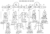
특히, 도 5a를 참조하면, 하나 또는 두 증폭기의 이득 매질이 펌프 광을 수광할 때, 펄스 발생기는 연속적인 방식으로 작동을 시작하지만, CW 방사선의 원하는 스펙트럼 영역에서 레이저 잡음이 크게 변동한다. 후자는 하나 이상의 저 강도 피치(38)(1개만 도시됨)를 특징으로 하는 스펙트럼을 갖고, 각각의 저 강도 피치는 단계 1 및 2에 도시된 바와 같이 시간 영역(34)에서 확장되고 좁은 스펙트럼 선폭(36)을 갖는다. 원하는 스펙트럼 영역 내의 잡음이 입력 커플러(32)를 통과할 때(단계 2), 피치(38)의 스펙트럼이 약간 확장되기만 한다. 다수의 펌프(26)로 인해, 피치에서 신호로의 2개의 신호 발현 프로세스가 실질적으로 동시에 또는 매우 짧은 시간 지연 내에 링 도파관에서 발생하지만, 명확성을 위해, 프로세스 중 하나만을 상세하게 추가로 개시한다. In particular, referring to FIG. 5A, when the gain medium of one or both amplifiers receives the pump light, the pulse generator starts operating in a continuous manner, but the laser noise in the desired spectral range of CW radiation varies greatly. The latter has a spectrum characterized by one or more low intensity pitches 38 (only one is shown), each low intensity pitch extending in
시드 주입 단계의 단계 3에서, 제1 증폭기(12)는 피치(38)의 피크 강도를 증가시키도록 작동한다. 제1 코일(16)을 통해 더 전파하면서, 피치(38)는 시간 영역에서 확장되며, 증가된 피크 강도에 의해 유도되는 비교적 약한 자기 위상 변조 비선형 효과(SPM)로 인해 단계 4에 도시된 바와 같이 주파수 영역에서 스펙트럼이 확장된다. 그러나, 후자는 상당한 스펙트럼 확장에는 여전히 충분하지 않다. 이와 같이 증폭되고 확장된 피치(38)(이 시점에서, 출력 커플러(30)에서의 파워 손실은 단계 5에 도시된 바와 같이 미미하다)는 제1 필터(18)에 결합된다. 후자는, 예컨대, 원하는 주파수 범위의 장 파장을 구분하도록 구성되며, 즉, 이는 단계 6에 도시된 바와 같이 단 파장의 서브-영역은 통과시키는 반면 장 파장은 차단한다. 물론, 필터(18)는 단 파장은 차단하는 반면 장 파장의 서브-영역은 통과시키도록 구성될 수 있다. In
제1 필터(18)의 출력에서의 과도 펄스는 제2 증폭기(20)에서 더 시드되며, 제2 증폭기는 단계 7에 도시된 바와 같이 피치의 피크 강도를 상당히 증가시킨다. 그리고, 후자는 단계 8에 도시된 바와 같이 제1 섬유 코일(16)에서보다 더 강한 위상 변조를 제2 섬유 코일(22)에서 유도한다. 실제로, 피치(38)의 선단(장 파장) 에지를 따라 새로 발생된 주파수 성분은 단계 9에서 볼 수 있는 바와 같이 이 예시적인 체제에서 단 파장을 구분하도록 구성된 제2 필터(24)의 통과 대역으로 진입한다. 제2 필터(24)의 출력에서, 피치의 모드들은 고정된 위상 관계를 갖고, 즉, 모드들이 동기화된다. 그러나, 피치(38)의 피크 강도나 스펙트럼 폭이 원하는 임계치에 아직 도달하지 않았다. The transient pulse at the output of the
이제, 도 5b를 참조하면, 이전의 불포화된 시드 주입 단계가 종료되는 과도 단계가 시작된다. 필터(24)로부터의 피치는 제1 증폭기(12)에 결합되며, 제1 증폭기에서는 제1 섬유 코일(16)에서 새로운 주파수를 발생시키는 SPM 효과를 유도하기에 충분한 수준으로 피크 강도가 다시 증가한다. 도 5a 및 도 5b의 각각의 동일한 단계 4를 비교하면, 시드 주입 단계에 비해 과도 단계 중에 피치가 스펙트럼 영역에서 실질적으로 확장되고 시간 영역에서 신장되는 것을 명확하게 알 수 있다. 그러나, 피치(38)의 스펙트럼 폭이 제1 필터(18)의 통과 대역을 완전히 커버하기에는 아직 불충분할 수 있으며, 따라서, 제1 필터는 통과하는 과도 펄스의 장 파장을 다시 차단한다. 제2 증폭기(22)는 피치의 스펙트럼 폭과 지속 시간을 제2 섬유 코일(22)을 통해 전파할 때 각각 원하는 스펙트럼 폭과 지속 시간으로 확장하기에 충분한 원하는 수준으로 피크 강도를 마지막으로 증가시킨다. 원하는 스펙트럼 폭에 도달하면, 피치는 필터(24)의 통과 대역을 완전히 커버하는 제2 코일 후에 스펙트럼 폭을 갖는 신호(50)로 완전히 발현된다. 전술한 바와 같이, 원하는 신호로 완전히 발현되기 전에 피치(38)의 하나 이상의 왕복을 갖는 것으로서 기동 단계가 개시되어 있다. 이론적으로, 특정 조건하에서는, 원하는 신호(50)를 형성하기 위해 절반의 왕복이면 충분할 수 있으며, 이 경우에는, 시드 주입 단계에서 원하는 신호가 형성될 것이다. Referring now to FIG. 5B, a transient step is initiated in which the previous unsaturated seed implant step is terminated. The pitch from the
상기 설명은 펄스 발현을 강조하지만, CW 성분은 전술한 기동 아키텍처에서 중요한 역할을 한다. 링 공동(10)은 섬유 증폭기에서 높은 에너지의 축적을 의미하는 고품질 인자(Q)로 구성된다. 이 에너지가 감소되지 않으면, 본 발명의 링 도파관은 펄스 발생기가 쉽게 파괴될 수 있는 그와 같이 높은 수준의 에너지를 갖는 Q-스위치 펄스를 생성할 것이다. 에너지 감소는 도 4의 2개의 필터(18, 24)의 특수한 구성에 의해 실현된다. 각각의 필터의 중심 파장(λc1, λc2)은 도 4에 도시된 바와 같이 필터의 통과 대역 중 하나가 다른 필터의 통과 대역에 중첩하도록 선택된다. 2개의 필터 사이에서 중첩된 스펙트럼 영역(40)은 두 증폭기에 축적된 에너지의 초과량을 소비하는 CW 성분의 전파를 허용한다. 그러나, CW 성분의 양은 주요 모드 잠금 프로세스와 경쟁하지 않도록 증폭되어야 한다. 필터들이 서로 다른 각각의 투과율 진폭을 갖는 경우, 중첩된 영역은 최고 투과율을 갖는 그 필터의 최대 필터 투과율의 10% 이하, 그러나, 바람직하게는, 최저 투과율을 갖는 필터의 0.1% 이상을 통과시킨다. 그러나, 필터들은 동일한 투과율 진폭으로 구성될 수 있다. 요약하면, 서로 중첩하는 각각의 통과 대역을 갖는 2개의 필터(18, 24)는 1. CW 방사선을 억제하고, 2. 안정적인 모드 잠금된 체제에서 원하는 신호로 피치를 발현시키기 위해 협력하여 기능한다. While the above description emphasizes pulse generation, the CW component plays an important role in the above-described startup architecture. The ring cavity 10 is composed of a high quality factor (Q), which means a high energy accumulation in the fiber amplifier. If this energy is not reduced, the ring waveguide of the present invention will produce Q-switched pulses with such a high level of energy that the pulse generator can be easily broken down. The energy reduction is realized by a special configuration of the two
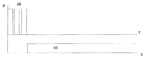
도 4와 함께 논의되는 도 7a는 상기 개시된 기동 아키텍처의 다른 특징을 예시하고 있으며, 원하는 주파수 영역에서 피치 또는 피치들의 증폭에 관한 것이다. 사실상, 어느 누구도 필터의 원하는 파장 범위 내에서 결국 끝나는 광대역 저 주파수 잡음 내에서 약한 피치의 증폭을 시작하는데 얼마나 많은 시간이 필요한지를 모른다. 발현되는 피치가 원하는 파장 범위 내에 있도록 보장하기 위해, 각각의 펌프(26)는 전류 변조 입력을 갖는다. 처음에, 몇 분의 1 밀리초 내지 수 밀리초의 펌프 광(42)(도 7a)의 프리펄스 또는 프리펄스들을 발사하는 높은 진폭 및 짧은 지속 시간이 링 도파관(10)(도 4)에 결합된 다음, 펌프(26)로의 입력이 대략 초기 펌프 광의 지속 시간 동안 중단된다. 이러한 스위치-온/스위치-오프 동작은 원하는 주파수 영역 내에서 하나 이상의 과도 펄스를 필연적으로 증폭하는 넓은 범위의 광대역 저 주파수 잡음 위에 순간적으로 축적된 에너지가 분산될 수 있도록 허용한다. 그 후, 펌프(26)는 다시 스위치 온되며, 적어도 펄스 발생기가 작동하는 동안에는, 프리펄스의 진폭보다 낮은 진폭을 갖는 CW 펌프 광(44)을 출력하는 CW 체제에서 중단되지 않고 작동한다. CW 펌프 진폭은 출력 신호의 매개 변수를 조정하기 위해 달라질 수 있다.Fig. 7a, discussed in conjunction with Fig. 4, illustrates another feature of the disclosed startup architecture and relates to the amplification of pitch or pitch in the desired frequency domain. In fact, no one knows how much time is required to begin amplifying a weak pitch within broadband low frequency noise, which eventually ends within the desired wavelength range of the filter. To ensure that the pitch being expressed is within the desired wavelength range, each pump 26 has a current modulation input. First, a high amplitude and short duration of firing pre-pulses or pre-pulses of pump light 42 (FIG. 7A) of a few milliseconds to several milliseconds is applied to ring waveguide 10 (FIG. 4) Next, the input to the
도 4 및 도 7b를 참조하면, 기동 단계의 대안적인 구성은, 펌프(26) 이외에, 시드 또는 시드(46)들을 포함하며(도 4), 이들은 펌프(26)가 작동을 시작하기 전에 턴-온되어 펌프 광(48)의 하나 이상의 균일한 에탈론 펄스를 출력한다(도 7a). 에탈론 펄스는, 펌프가 CW 펌프 광을 방출하기 시작한 직후, 시드가 단전된 후에 점진적으로 쇠퇴한다. 이 구성은, 전술한 구성과 마찬가지로, 섬유 레이저(12, 20)에 축적되는 에너지를 낮추는데 도움이 되며, Q 스위치 펄스의 발생을 방지한다. 원하는 펄스에서의 반복률과는 다르게 시드를 스위칭 온 및 오프하는 반복률로 링 도파관(10)을 통해 전파하는 에탈론 펄스는 링 공동으로부터 분리된다. 시드(46)의 사용은 링 도파관(10)의 구성을 다소 변경할 수도 있다. 도파관(10)의 변경된 구조는 서로 중첩하지 않는 각각의 통과 대역으로 구성된 필터(18, 24)를 가질 수 있다. 그러나, 이러한 변경이 필수적인 것은 아니며, 도 7a를 참조하여 개시된 링 도파관(10)의 변경되지 않은 구조가 이 제2 실시예를 실시하기에 적합할 수도 있다. 4 and 7B, an alternative configuration of the start-up phase includes seeds or seeds 46 (FIG. 4), in addition to the
도 5c 및 도 6a 내지 도 6d를 참조하면, 개시된 펄스 발생기의 정상 단계는, 여기에 도시된 바와 같이, 과도 단계의 끝에서 원하는 스펙트럼 폭을 갖는 신호(50)를 형성한 직후에 시작한다. 각각의 필터의 중첩된 통과 대역의 경우, 신호(50)의 원하는 스펙트럼 폭은 발현된 신호가 중첩된 영역을 통해 전파하도록 구성된다. 통과 대역이 중첩되지 않는 경우, 신호의 원하는 스펙트럼 폭은 후속 필터의 통과 대역과 중첩되도록 구성된다.Referring to Figures 5c and 6a-6d, the normal phase of the disclosed pulse generator begins immediately after forming the
특히, 신호(50)가 필터(18)를 통과할 때(도 6a), 후자는 도 6b에 도시된 바와 같이 중심 파장(λ1)에 센터링된 신호(50)를 남기고 모든 장 파장 모드를 필터링한다. 더 증폭하고 스펙트럼 확장하면, 신호(50)는 필터(24)의 전체 통과 대역을 중첩하기에 충분한 새로운 주파수를 취득하며, 이 필터는 필터(18)와는 반대로 모든 단 파장의 추가 전파를 차단한다(도 6c). 그 결과, 신호(50)는 이제 제2 중심 파장(λ2)에 센터링된다. 추가적으로 증폭하고 스펙트럼 확장하는 프로세스 자체가 링 공동에서 신호의 모든 절반의 왕복마다 반복된다. In particular, when the
신호(50)가 발현되면, 출력 커플러(30)(도 4)가 공동 외부로 펄스(55)를 안내하기 전에, 신호는 링 공동 주위(10)를 단지 1회 왕복한다. 바람직하게, 후자는 도 4에 점선으로 나타낸 바와 같이 제2 섬유 코일(22)의 출력에 직접 연결된 추가적인 출력 커플러(30)를 가질 수 있다. 이러한 구성은 모든 절반의 왕복마다 펄스(55)의 분리를 허용한다. Once the
전술한 펄스 발생기는 증폭기(12, 20)의 이득 매질에 사용되는 희토류 물질의 이온에 따라 임의의 원하는 작동 파장에서 작동할 수 있다. 예컨대, 이러한 희토류 물질은 이테르븀, 에르븀 및 툴륨을 포함할 수 있다. 그러나, 발광체로서 알려진 모든 다른 희토류 물질이 앞서 나열한 재료로서 성공적으로 사용될 수 있다. 구조적으로, 2개의 섬유 체인 이외에, 분리된 신호 광 펄스의 균일한 피크 파워를 보장하기 위해 추가적인 섬유 체인을 사용하는 것이 유리할 수 있다. The aforementioned pulse generator can operate at any desired operating wavelength depending on the ions of the rare earth material used in the gain medium of the
링 도파관(10)의 섬유 구성 요소는 양의 순 분산을 갖도록 구성될 수 있다. 후자는 모든 구성 요소가 정상 분산을 갖는 1 마이크론 파장 범위에서 특히 유리하다. 그러나, 도 4를 참조하면, 전체 양의 순 분산에 영향을 미치지 않는 음의 분산을 구비한 도시된 요소 중 하나를 갖는 1 마이크론 파장 범위에서 개시된 펄스 발생기를 사용하는 것이 가능하다. 예컨대, 양의 순 분산은 양(정상)의 분산을 갖도록 링 도파관(10)의 모든 구성 요소를 구성함으로써 얻어질 수 있다. 대안적으로, 하나 이상의 구성 요소는 변칙적(음의) 분산을 가질 수 있지만, 후자는 링 공동의 전체 양의 순 분산을 변화시키지 않는다. 예컨대, 필터(18, 24)들은 각각 또는 모두는 변칙적 분산을 갖도록 구성될 수 있으며, 1 마이크론 파장 범위에서 여전히 성공적으로 사용될 수 있다. 도파관(10)의 순 분산은 이상 분산을 갖도록 구성된 도파관 구성 요소의 전부 또는 대다수에 의해 변칙적이 될 수 있다. 마지막으로, 링 공동(10)의 순 분산은 제로일 수 있다. The fiber component of the ring waveguide 10 may be configured to have a positive net dispersion. The latter is particularly advantageous in the 1 micron wavelength range where all components have normal dispersion. However, referring to FIG. 4, it is possible to use a pulse generator disclosed in the 1 micron wavelength range with one of the illustrated elements with negative dispersion that does not affect the net positive dispersion. For example, a positive net dispersion of positive can be obtained by constructing all the components of the ring waveguide 10 so as to have a positive (normal) dispersion. Alternatively, one or more of the components may have an anomalous (negative) dispersion, but the latter does not change the net dispersion of the total amount of the ring cavity. For example, each of the
바람직하게, 도파관(10)의 모든 섬유 구성 요소는 편광 유지(PM) 포맷으로 구성된다. 그러나, 그 구성 요소 중 일부 또는 모든 구성 요소가 PM 구성 요소가 아닐 수 있다. Preferably, all fiber components of the waveguide 10 are configured in a polarization maintaining (PM) format. However, some or all of the components may not be PM components.
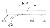
도 8 및 도 9를 참조하면, 증폭기(12, 20)는 입력 및 출력 수동 섬유(130)에 대향 단부가 연결되는 희토류 이온 도프 섬유(128)의 조합을 각각 포함한다. 섬유(128)는 단일 가로 모드 또는 다중 가로 모드(MM)만을 지원할 수 있는 코어(132)를 갖는다. 그러나, 원하는 작동 파장에서, 예컨대, 1.06마이크론에서, MM 섬유(128)의 코어(132)는 우측 도펀트 프로파일을 선택함으로써 하나의 기본 모드만을 지원하도록 구성된다. 즉, SM 광이 능동 섬유(128)의 MM 코어(132)에 결합될 때, 이는 관련 기술 분야의 기술자에게 공지된 바와 같이 SM 섬유와 유사한 가우시안(Gaussian) 형상의 강도 프로파일에 가까운 기본 가로 모드만을 여기시킨다. 이와 같이 발생된 펄스(55)(도 4)는 단일 가로 모드의 펄스 발생기로부터 방출된다. 또한, 섬유(128)는 측면 펌핑 체제에서 SM 코어를 가질 수 있다.8 and 9, the
MM 섬유는 반드시 SM 능동 섬유와 함께 단부 펌핑 체제보다 나은 어떤 장점을 가질 수 있는 측면 펌핑 체제를 사용할 수 있는 기회를 증폭기에 제공한다. 첫째, 측면 펌핑 체제는 제한된 파워만을 견딜 수 있는 파장 분할 멀티플렉서(WDM)의 사용을 필요로하지 않는다. 그 결과, 측면 펌핑 체제의 다른 장점은, 당연히 MM 능동 섬유의 대안이 될 수 있는, SM 능동 섬유보다 높은 파워를 갖는 펄스를 발생시킬 수 있는 가능성이다. 그러나, 관련 기술 분야의 기술자는 공지된 단부 펌핑 기술을 용이하게 실현할 수 있다. MM fibers provide the amplifier with the opportunity to use a side pumping arrangement that may have some advantage over the end pumping arrangement with SM active fibers. First, the side pumping system does not require the use of a wavelength division multiplexer (WDM) that can withstand only limited power. As a result, another advantage of the side pumping scheme is the possibility of generating pulses with higher power than SM active fibers, which, of course, can be an alternative to MM active fibers. However, those skilled in the relevant art can readily realize the known end pumping technique.
도 9는 이중 병목 형상의 단면을 갖는 MM 능동 섬유(128)를 도시하고 있다. 이 변형예는 코어 단부(134)보다 큰 직경을 중앙 확대 코어부(132)에 제공한다. 확대된 코어부(132)는 더 큰 펌프 파워와 감소된 섬유 길이를 제공하며, 이는 기본 모드와 고차 모드 간의 결합 가능성을 최소화한다. 코어 단부(134)는 도 7의 단부와 유사하게 구성되며, SM 수동 섬유와 일치하는 MFD를 각각 갖는다. Figure 9 shows a MM
링 도파관(10)을 구성하는 요소들은 양, 음 및 제로 분산 및 이들의 조합을 가질 수 있다. 예컨대, 동시 계류중인 미국 출원으로부터 공지된 바와 같이, 1 마이크론 파장 범위에서 사용하기 위해 총 양의 분산을 갖도록 링 공동을 구성한다. 링 공동은 링 공동에 양의 분산을 전체적으로 제공하는 다양한 유형의 분산을 갖는 복수의 섬유 구성 요소를 포함한다.The elements constituting the ring waveguide 10 may have positive, negative and zero dispersion and combinations thereof. For example, as is known from co-pending U. S. application, a ring cavity is constructed to have a total amount of dispersion for use in the 1 micron wavelength range. The ring cavity includes a plurality of fiber components having various types of dispersions that provide a positive dispersion throughout the ring cavity.
독자는 본 명세서와 동시에 제출되고 본 명세서와 함께 공람되는 모든 서류와 문서에 관심을 가지며, 그러한 모든 서류와 문서의 내용은 본원에 참조로 인용된다.The reader is interested in all documents and documents submitted at the same time as this specification and which are accompanied by this specification, the contents of all such documents and documents being incorporated herein by reference.
Claims (30)
각각의 섬유 체인은,
신호의 강도를 원하는 강도로 증가시키도록 작동하는 섬유 증폭기;
신호의 스펙트럼 폭을 광 섬유의 출력에서 원하는 스펙트럼 폭으로 확장하기에 충분한 원하는 강도를 갖는 신호를 수신하는 광 섬유; 및
광 섬유의 출력에 결합되고 통과 대역을 갖는 스펙트럼 필터로 구성되고,
섬유 체인의 각각의 광학 필터의 통과 대역은 스펙트럼적으로 서로 이격된 각각의 주파수 성분에 센터링되어 신호가 순차적으로 각각의 필터의 통과 대역에 중첩될 수 있도록 하며,
섬유 체인 중 적어도 하나는, 광 섬유의 출력에 직접 결합되어 링 공동 외부로 원하는 스펙트럼 폭, 지속 시간 및 에너지를 갖는 펄스를 안내하도록 구성된 출력 커플러를 포함하는, 섬유 펄스 발생기. A fiber pulse generator including a plurality of fiber chains coupled together to form a ring cavity that emits a train of pulses each having a desired spectral width, duration and energy, and which guides the signal in one direction,
Each of the fiber chains,
A fiber amplifier operative to increase the intensity of the signal to a desired intensity;
An optical fiber that receives a signal having a desired intensity sufficient to extend the spectral width of the signal to the desired spectral width at the output of the optical fiber; And
A spectral filter coupled to the output of the optical fiber and having a passband,
The passband of each optical filter of the fiber chain is centered on each spectrally separated frequency component so that the signal can be sequentially superimposed on the passband of each filter,
Wherein at least one of the fiber chains comprises an output coupler coupled directly to the output of the optical fiber and configured to direct a pulse having a desired spectral width, duration and energy out of the ring cavity.
섬유 증폭기에 결합되고 펄스의 파장과는 다른 파장을 갖는 CW 방사선을 각각 발사하는 복수의 펌프; 및
펌프를 턴 온하기 전에 신호를 발생시키기 위해 각각의 에탈론 펄스를 각각 출력하는 복수의 시드 소스로서, 상기 시드 소스는 펌프가 턴 온된 후에 단전되며, 에탈론 펄스는 신호 펄스의 반복률과는 다른 반복률로 링 공동 주위로 전파하고, 섬유 증폭기에 결합되었을 때, 내부에 축적된 에너지를 링 공동에서 Q 스위치 펄스를 발현하기에는 불충분한 에너지 수준으로 낮추는, 복수의 시드 소스를 추가로 포함하는, 섬유 펄스 발생기.The method according to claim 1,
A plurality of pumps coupled to the fiber amplifier and each emitting CW radiation having a wavelength different from the wavelength of the pulses; And
A plurality of seed sources each outputting a respective etalon pulse for generating a signal before turning the pump on, the seed source being cut off after the pump is turned on, the etalon pulse having a repetition rate different from the repetition rate of the signal pulse Further comprising a plurality of seed sources that propagate around the Lo ring cavity and, when coupled to the fiber amplifier, lower the accumulated energy therein to an insufficient energy level for expressing a Q switch pulse in the ring cavity. .
각각의 광학 필터의 중심 주파수들은 스펙트럼적으로 서로 중첩되지 않고, CW 방사선의 01.% 미만을 통과시키기 위해 연속파("CW") 방사선이 링 공동 또는 중첩부를 통해 전파하지 않도록 차단하는, 섬유 펄스 발생기. 3. The method of claim 2,
The center frequencies of each optical filter are not superimposed spectrally on one another and block the continuous wave ("CW") radiation from propagating through the ring cavity or overlap to pass less than 0.1% of the CW radiation, .
복수의 펌프를 추가로 포함하고, 복수의 펌프 각각은,
먼저, 각각 2개의 섬유 체인의 섬유 증폭기, 섬유 및 필터를 통해 전파하는 적어도 하나의 피치를 포함하여, 그 피치를 원하는 스펙트럼 폭과 강도를 갖는 신호로 발현시키는데 도움을 주는, 필요한 스펙트럼 영역 내에 잡음을 발생시키기에 충분한 프리펄스를 출력한 후,
CW 방사선을 출력하도록 구성되고,
각각의 광학 필터의 중심 주파수들은 각각의 광학 필터의 통과 대역들이 서로 중첩하도록 스펙트럼적으로 이격되고, 중첩된 통과 대역들 사이의 스펙트럼 영역은 섬유 증폭기에 축적된 에너지를 Q 스위치 펄스를 발현하기에는 불충분한 수준으로 감소시키기에 충분한 링 공동을 따라 CW 방사선의 필터링되지 않은 부분의 순환을 제공하도록 구성되며, 필터는 서로 동일하거나 서로 상이한 각각의 투과 진폭으로 구성되는, 섬유 펄스 발생기.The method according to claim 1,
Wherein the pump further comprises a plurality of pumps,
First, it comprises at least one pitch propagating through the fiber amplifiers, fibers and filters of two fiber chains, respectively, to produce noise in the required spectral range, which helps to express the pitch as a signal with the desired spectral width and intensity After outputting a pre-pulse sufficient for generating,
CW radiation,
The center frequencies of each optical filter are spectrally spaced such that the passbands of each optical filter overlap each other and the spectral region between the overlapping passbands is such that the energy accumulated in the fiber amplifier is insufficient to generate a Q switch pulse Wherein the filters are configured to provide respective circulation of the unfiltered portion of the CW radiation along a ring cavity sufficient to reduce the radiation dose to a level that is equal to or different from each other.
최고 투과율을 갖는 필터 중 하나의 최대 투과율의 10% 미만을 통과시키도록 구성된 스펙트럼 영역을 사이에 형성하기 위해 각각의 필터의 통과 대역이 서로 중첩하도록, 각각의 광학 필터의 중심 주파수가 이격되는, 섬유 펄스 발생기.5. The method of claim 4,
Wherein the center frequency of each optical filter is spaced apart so that the passbands of each filter overlap to form a spectral region configured to pass less than 10% of the maximum transmittance of one of the filters with the highest transmittance, Pulse generator.
중첩된 구역은 최저 투과율을 갖는 다른 필터의 최대 투과율의 최대 0.1%를 통과시키도록 구성되는, 섬유 펄스 발생기. 6. The method of claim 5,
Wherein the overlapping region is configured to pass at most 0.1% of the maximum transmittance of the other filter having the lowest transmittance.
프리펄스는 몇 분의 1 밀리초에서 수 밀리초까지 다양할 수 있는 펄스 지속 시간 및 CW 펌프 신호의 파워보다 큰 파워를 갖는, 섬유 펄스 발생기. 5. The method of claim 4,
The pre-pulse has a pulse duration that can vary from a fraction of a millisecond to a few milliseconds, and a power greater than the power of the CW pump signal.
각각의 섬유 체인은 정상 순 분산 또는 변칙적 순 분산을 갖도록 구성되고, 스펙트럼적으로 확장된 신호 펄스는 섬유 체인을 통해 전파하면서 시간적으로 신장되는, 섬유 펄스 발생기. The method according to claim 1,
Wherein each fiber chain is configured to have a normal net dispersion or anomalous net dispersion and the spectrally extended signal pulse is stretched in time as it propagates through the fiber chain.
링 공동을 형성하는 섬유 체인은 각각 제로 순 분산을 갖도록 구성되는, 섬유 펄스 발생기. The method according to claim 1,
Wherein the fiber chains forming the ring cavities are each configured to have a zero net dispersion.
스펙트럼적으로 확장된 신호 펄스는 선형적으로 처프된 펄스인, 섬유 펄스 발생기. The method according to claim 1,
A spectrally extended signal pulse is a linearly chirped pulse.
다른 광 섬유의 출력에 결합된 추가적인 출력 커플러를 추가로 포함하며, 원하는 스펙트럼 폭, 강도 및 에너지를 갖는 펄스는 절반의 왕복마다 링 공동으로부터 출력되는, 섬유 펄스 발생기. The method according to claim 1,
Further comprising an additional output coupler coupled to the output of the other fiber, wherein the pulse having the desired spectral width, intensity and energy is output from the ring cavity every half round trip.
각각의 스펙트럼 필터의 통과 대역은 각각의 동일한 대역폭 또는 동일한 진폭 투과율 또는 동일한 대역폭과 투과 진폭을 갖는, 섬유 펄스 발생기. The method according to claim 1,
Wherein the passbands of each spectral filter have respective equal bandwidths or equal amplitude transmissions or equal bandwidth and transmission amplitudes.
각각의 스펙트럼 필터의 통과 대역은 서로 다른 대역폭을 갖고, 대역폭 중 하나는 다른 대역폭보다 최대 5배 더 큰, 섬유 펄스 발생기. The method according to claim 1,
The passband of each spectral filter has a different bandwidth, and one of the bandwidths is up to five times greater than the other bandwidth.
각각의 섬유 체인은 편광 유지(PM) 포맷으로 구성되거나, PM 포맷이 아닌, 섬유 펄스 발생기. The method according to claim 1,
Each fiber chain consists of a polarization maintaining (PM) format or a fiber pulse generator, not a PM format.
순차적으로 발사된 에탈론 펄스는 섬유 증폭기에 축적된 에너지를 링 공동에서 Q 스위치 펄스를 발현하기에는 불충분한 수준으로 낮추기 위해 각각 점진적으로 감소하는 진폭 또는 균일한 진폭을 갖는, 섬유 펄스 발생기. 8. The method of claim 7,
The sequentially emitted etalon pulses each have a gradually decreasing amplitude or a uniform amplitude to lower the energy accumulated in the fiber amplifier to an insufficient level in the ring cavity to develop a Q switch pulse.
각각의 섬유 증폭기는 대향하는 비교적 작은 균일한 직경의 단부 영역 및 단부 영역의 직경보다 큰 직경을 갖는 중앙의 균일하게 구성된 영역을 구비하는 다중모드 코어를 갖고, 다중모드 코어는 신호 펄스의 작동 파장에서 기본 모드만을 지원하도록 구성되는, 섬유 펄스 발생기. The method according to claim 1,
Each fiber amplifier has a multimode core with a uniformly configured central region having a diameter that is greater than the diameter of the end region and a relatively small uniform diameter end opposite the multimode core, A fiber pulse generator configured to support only the basic mode.
각각의 섬유 증폭기는 단일 가로 모드 능동 섬유로 구성되는, 섬유 펄스 발생기. The method according to claim 1,
Each fiber amplifier being composed of a single transverse mode active fiber.
각각의 증폭기의 각각의 대향 단부에 결합된 단일 가로 모드 수동 섬유를 추가로 포함하는, 섬유 펄스 발생기. 18. The method according to claim 16 or 17,
Further comprising a single transverse mode passive fiber coupled to each opposed end of each of the amplifiers.
2개의 섬유 체인 사이에 결합된 적어도 하나의 아이솔레이터를 추가로 포함하는, 섬유 펄스 발생기. The method according to claim 1,
Further comprising at least one isolator coupled between the two fiber chains.
링 공동 내로 시드 소스와 펌프의 출력을 안내하는 입력 커플러를 추가로 포함하는, 섬유 펄스 발생기. The method according to claim 5 or 7,
Further comprising an input coupler for guiding the output of the pump and the seed source into the ring cavity.
펌프는 각각의 증폭기의 측면 펌프 또는 단부 펌프로 구성되는, 섬유 펄스 발생기. The method according to claim 5 or 7,
The pump is composed of a side pump or an end pump of each amplifier.
각각의 필터의 통과 대역 각각은 펄스의 원하는 스펙트럼 폭보다 좁거나 넓은, 섬유 펄스 발생기. The method according to claim 1,
Each of the passbands of each filter is narrower or wider than the desired spectral width of the pulse.
하나가 다른 하나에 결합되어 링 공동을 형성하는 복수의 섬유 체인으로서, 각각의 섬유 체인은 섬유 증폭기, 펄스 처프 성분, 및 펄스 처프 성분의 출력에 결합되며 통과 대역을 갖는 광학 필터를 포함하는, 복수의 섬유 체인; 및
처프 성분의 출력에 직접 결합되어 링 공동 외부로 펄스를 안내하는 출력 커플러를 포함하고,
섬유 체인의 각각의 광학 필터의 통과 대역은 스펙트럼적으로 서로 이격된 각각의 주파수 성분에 센터링되는, 링 공동 섬유 레이저. A ring cavity fiber laser that generates and outputs an ultra-high speed pulse,
A plurality of fiber chains, one of which is coupled to the other to form a ring cavity, each fiber chain comprising an optical filter coupled to an output of a fiber amplifier, a pulse chirp component, and a pulse chirp component, Fiber chains; And
And an output coupler directly coupled to the output of the chirp component to direct the pulse outside the ring cavity,
Wherein the passband of each optical filter of the fiber chain is centered on each frequency component that is spectrally separated from each other.
펄스 처프 성분은 광 섬유의 길이인, 링 공동 섬유 레이저. 24. The method of claim 23,
Wherein the pulse chirp component is the length of the optical fiber.
각각 이격된 중심 파장에 센터링된 숏패스 및 롱패스 스펙트럼 필터를 통해 신호를 순차적으로 통과시킴으로써, 신호의 스펙트럼 영역의 각각의 단파장 및 장파장 서브 영역을 순차적으로 통과시키는 단계; 및
신호의 왕복당 적어도 한번 초단 펄스를 링 공동으로부터 분리시키는 단계를 포함하는, 방법. A method for generating a train of short pulses in a fiber ring cavity laser,
Sequentially passing each of the short wavelength and long wavelength sub-regions of the spectral region of the signal by sequentially passing the signal through short path and long path spectral filters centered at respective spaced central wavelengths; And
Separating at least one second-order pulse per reciprocation of the signal from the ring cavity.
각각 필터링하기 전에 신호를 원하는 피크 강도로 증폭하는 단계; 및
필터링하기 전에 섬유 처프 성분에서 증폭된 신호를 스펙트럼적으로 확장시키는 단계를 추가로 포함하는, 방법. 26. The method of claim 25,
Amplifying the signal to a desired peak intensity before each filtering; And
Further comprising spectrally expanding the amplified signal in the fiber chirp component prior to filtering.
단파장 및 장파장 필터는 각각의 필터의 통과 대역이 서로 중첩하지 않도록 이격된 각각의 중심 파장을 갖는, 방법. 27. The method of claim 26,
Wherein the short wavelength and long wavelength filters have respective center wavelengths spaced apart such that the passbands of the respective filters do not overlap each other.
단파장 및 장파장 필터는 각각의 필터의 통과 대역이 서로 중첩하도록 이격된 각각의 중심 파장을 갖는, 방법. 27. The method of claim 26,
Wherein the short wavelength and long wavelength filters have respective center wavelengths spaced such that the passbands of the respective filters overlap each other.
제1 기간 동안 링 공동 내로 하나 이상의 에탈론 펄스를 주입하는 단계; 및
제1 기간 동안 링 공동 내부에 CW 및 피치 성분을 포함한 CW 방사선을 발생시키는 단계;
피치 성분을 신호로 발현시키는 단계; 및
피치 성분을 발현시키는 동안 에탈론 펄스의 주입을 중단하는 단계를 추가로 포함하는, 방법. 28. The method of claim 27,
Injecting at least one etalon pulse into the ring cavity for a first period of time; And
Generating CW radiation including CW and pitch components within the ring cavity for a first period of time;
Expressing the pitch component as a signal; And
Further comprising the step of stopping the injection of the etalon pulse while expressing the pitch component.
일정한 기간 동안 링 공동 내로 펌프의 프리펄스를 주입하는 단계; 및
그 후, 링 공동 내로 CW 방사선을 결합하는 단계를 추가로 포함하는, 방법. 29. The method of claim 28,
Injecting a pre-pulse of the pump into the ring cavity for a period of time; And
And then coupling the CW radiation into the ring cavity.
Applications Claiming Priority (3)
| Application Number | Priority Date | Filing Date | Title |
|---|---|---|---|
| US201462091817P | 2014-12-15 | 2014-12-15 | |
| US62/091,817 | 2014-12-15 | ||
| PCT/US2015/065798 WO2016100330A1 (en) | 2014-12-15 | 2015-12-15 | Passively mode-locked fiber ring generator |
Publications (2)
| Publication Number | Publication Date |
|---|---|
| KR20170101880A true KR20170101880A (en) | 2017-09-06 |
| KR102218499B1 KR102218499B1 (en) | 2021-02-19 |
Family
ID=56127463
Family Applications (1)
| Application Number | Title | Priority Date | Filing Date |
|---|---|---|---|
| KR1020177003349A KR102218499B1 (en) | 2014-12-15 | 2015-12-15 | Passively mode-locked fiber ring generator |
Country Status (9)
| Country | Link |
|---|---|
| US (1) | US10193296B2 (en) |
| EP (1) | EP3235076B1 (en) |
| JP (1) | JP6657178B2 (en) |
| KR (1) | KR102218499B1 (en) |
| CN (1) | CN106716749B (en) |
| BR (1) | BR112017004051B1 (en) |
| CA (1) | CA2955503C (en) |
| RU (1) | RU2690864C2 (en) |
| WO (1) | WO2016100330A1 (en) |
Families Citing this family (13)
| Publication number | Priority date | Publication date | Assignee | Title |
|---|---|---|---|---|
| RU2633285C1 (en) * | 2016-07-05 | 2017-10-11 | Федеральное государственное автономное образовательное учреждение высшего образования "Новосибирский национальный исследовательский государственный университет" (Новосибирский государственный университет, НГУ) | Fibre operating generator |
| CN108963736B (en) * | 2018-08-16 | 2019-08-13 | 深圳番越光电有限公司 | A kind of high-peak power picosecond and nanosecond short-wavelength light fibre laser |
| JP2021536133A (en) * | 2018-09-05 | 2021-12-23 | アイピージー フォトニクス コーポレーション | Pulse configurable fiber laser unit |
| CN109687269B (en) * | 2019-01-24 | 2020-07-31 | 中国科学院西安光学精密机械研究所 | 1.7 mu m mode-locked fiber laser based on thulium-doped quartz fiber |
| CN109698458B (en) * | 2019-01-24 | 2020-02-07 | 广东朗研科技有限公司 | Nonlinear loop filtering Mamyshev type laser oscillator |
| KR20210118167A (en) * | 2019-01-31 | 2021-09-29 | 아이피지 포토닉스 코포레이션 | Ultrashort Pulsed Laser Source with Chirped Pulse Amplification and Custom Pulse Train |
| CN110061410B (en) * | 2019-05-06 | 2021-04-13 | 华南师范大学 | Mode-locked oscillator |
| RU2729064C1 (en) * | 2019-11-14 | 2020-08-04 | Валерий Владимирович Крюков | Method of converting nuclear energy (energy of radioactive decay and/or fission) into optical energy and device for implementation thereof |
| CN110911948A (en) * | 2019-11-29 | 2020-03-24 | 西安奇芯光电科技有限公司 | Chirp management laser based on hybrid integration technology |
| JPWO2021246531A1 (en) * | 2020-06-05 | 2021-12-09 | ||
| CN112234417A (en) * | 2020-10-19 | 2021-01-15 | 杭州奥创光子技术有限公司 | All-fiber femtosecond laser and method thereof |
| RU206388U1 (en) * | 2020-12-29 | 2021-09-08 | федеральное государственное бюджетное образовательное учреждение высшего образования "Московский государственный технический университет имени Н.Э. Баумана (национальный исследовательский университет)" (МГТУ им. Н.Э. Баумана) | Fiber thulium power amplifier for ultrashort pulses at a wavelength of 1.9 μm |
| CN113161863B (en) * | 2021-03-05 | 2023-06-27 | 电子科技大学 | Microwave pulse generating device and method based on time domain mode locking photoelectric oscillator |
Citations (1)
| Publication number | Priority date | Publication date | Assignee | Title |
|---|---|---|---|---|
| JP2006324613A (en) * | 2005-05-17 | 2006-11-30 | Alnair Labs:Kk | Passive mode-locking short pulsed light fiber laser and scanning pulsed laser |
Family Cites Families (17)
| Publication number | Priority date | Publication date | Assignee | Title |
|---|---|---|---|---|
| US4835778A (en) | 1987-09-30 | 1989-05-30 | Spectra-Physics, Inc. | Subpicosecond fiber laser |
| US6643299B1 (en) * | 2000-07-17 | 2003-11-04 | Calmar Optcom, Inc. | Bi-metal and other passive thermal compensators for fiber-based devices |
| JP3948598B2 (en) * | 2000-09-01 | 2007-07-25 | 富士通株式会社 | Method, apparatus and system for processing optical signals |
| WO2002025783A2 (en) * | 2000-09-22 | 2002-03-28 | Calmar Optcom, Inc. | Actively mode-locked fiber laser with controlled chirp output |
| EP1318579A1 (en) * | 2001-12-10 | 2003-06-11 | Corning Incorporated | Multi-wavelength raman laser |
| US7251258B2 (en) | 2002-12-12 | 2007-07-31 | Cornell Research Foundation, Inc. | Femtosecond ytterbium fiber laser with photonic crystal fiber for dispersion control |
| AU2003299854A1 (en) | 2002-12-20 | 2004-07-22 | Alnaire Laboratories Corporation | Optical pulse lasers |
| EP1812823A4 (en) * | 2004-03-25 | 2009-08-05 | Imra America Inc | Optical parametric amplification, optical parametric generation, and optical pumping in optical fibers systems |
| US7602825B1 (en) * | 2004-10-20 | 2009-10-13 | Calmar Optcom, Inc. | Tunable passively mode-locked lasers with phase-lock feedback for low timing jitters |
| US7633977B2 (en) * | 2007-08-08 | 2009-12-15 | Wisconsin Alumni Research Foundation | Multispectral laser with improved time division multiplexing |
| JP5495506B2 (en) * | 2008-05-13 | 2014-05-21 | キヤノン株式会社 | Laser apparatus and optical tomographic imaging apparatus |
| CN102273027B (en) | 2008-11-12 | 2014-06-25 | 康奈尔大学 | Giant-chirp oscillator for use in fiber pulse amplification system |
| US8934509B2 (en) * | 2009-11-23 | 2015-01-13 | Lockheed Martin Corporation | Q-switched oscillator seed-source for MOPA laser illuminator method and apparatus |
| US8494014B2 (en) * | 2011-04-08 | 2013-07-23 | Auckland Uniservices Limited | Laser device |
| US10608400B2 (en) | 2011-10-04 | 2020-03-31 | Cornell University | Fiber source of synchronized picosecond pulses for coherent Raman microscopy and other applications |
| LT6261B (en) * | 2014-08-06 | 2016-04-11 | Valstybinis mokslinių tyrimų institutas Fizinių ir technologijos mokslų centras | Method and generator for generation ultra-short light pulses |
| RU2605639C1 (en) * | 2015-06-30 | 2016-12-27 | Общество с ограниченной ответственностью "НАУЧНО-ТЕХНИЧЕСКОЕ ОБЪЕДИНЕНИЕ "ИРЭ-Полюс" (ООО НТО "ИРЭ-Полюс") | Method and devise for stabilizing optical power and spectral composition of radiation of fibre laser of ultrashort pulses |
-
2015
- 2015-12-15 CA CA2955503A patent/CA2955503C/en active Active
- 2015-12-15 US US15/536,170 patent/US10193296B2/en active Active
- 2015-12-15 KR KR1020177003349A patent/KR102218499B1/en active IP Right Grant
- 2015-12-15 CN CN201580051448.9A patent/CN106716749B/en active Active
- 2015-12-15 WO PCT/US2015/065798 patent/WO2016100330A1/en active Application Filing
- 2015-12-15 EP EP15870869.3A patent/EP3235076B1/en active Active
- 2015-12-15 BR BR112017004051-4A patent/BR112017004051B1/en active IP Right Grant
- 2015-12-15 RU RU2017102982A patent/RU2690864C2/en active
- 2015-12-15 JP JP2017505469A patent/JP6657178B2/en active Active
Patent Citations (1)
| Publication number | Priority date | Publication date | Assignee | Title |
|---|---|---|---|---|
| JP2006324613A (en) * | 2005-05-17 | 2006-11-30 | Alnair Labs:Kk | Passive mode-locking short pulsed light fiber laser and scanning pulsed laser |
Also Published As
| Publication number | Publication date |
|---|---|
| BR112017004051B1 (en) | 2022-06-07 |
| RU2017102982A (en) | 2019-01-17 |
| KR102218499B1 (en) | 2021-02-19 |
| CN106716749B (en) | 2019-11-15 |
| RU2690864C2 (en) | 2019-06-06 |
| EP3235076A4 (en) | 2018-08-08 |
| CA2955503A1 (en) | 2016-06-23 |
| US20170365972A1 (en) | 2017-12-21 |
| EP3235076B1 (en) | 2022-03-16 |
| BR112017004051A2 (en) | 2017-11-28 |
| EP3235076A1 (en) | 2017-10-25 |
| JP2018502434A (en) | 2018-01-25 |
| JP6657178B2 (en) | 2020-03-04 |
| CN106716749A (en) | 2017-05-24 |
| CA2955503C (en) | 2021-04-13 |
| RU2017102982A3 (en) | 2019-05-14 |
| US10193296B2 (en) | 2019-01-29 |
| WO2016100330A1 (en) | 2016-06-23 |
Similar Documents
| Publication | Publication Date | Title |
|---|---|---|
| KR102218499B1 (en) | Passively mode-locked fiber ring generator | |
| KR102528882B1 (en) | Pulsed laser systems with time-modulated rate and/or amplitude | |
| US20220337017A1 (en) | Method for generating gigahertz bursts of pulses and laser apparatus thereof | |
| WO2016145523A1 (en) | Passive mode-locked laser system and method for generation of long pulses | |
| JP2018531524A6 (en) | Pulse laser system with variable rhythm and / or amplitude over time | |
| WO2016020188A1 (en) | Method and generator for generating ultra-short light pulses | |
| US6937626B2 (en) | Multiple wavelength pulsed source | |
| Zhou et al. | Transform-limited, injection seeded, Q-switched, ring cavity fiber laser | |
| EP3300191B1 (en) | A saturable absorber and a method of mode-locking in a laser | |
| US10367327B2 (en) | Giant-chirp all-normal-dispersion sub-nanosecond fiber oscillator | |
| EP2827461B1 (en) | Method and laser source for generation of optically synchronized dual-wavelength ultrashort light pulses | |
| Barmenkov et al. | Pulsed regimes of erbium-doped fiber laser Q-switched using acousto-optical modulator | |
| JP2018535561A (en) | Pulse laser system with variable rhythm and / or amplitude over time | |
| WO2019053487A1 (en) | Stabilized laser or optical amplifier and stabilization method | |
| Semaan et al. | Roadmap to high-energy square pulses in anomalous dispersion fiber lasers | |
| Iezzi et al. | Wavelength tunable GHz repetition rate picosecond pulse generator using an SBS frequency comb | |
| Khalilah Zatiliman | Bandwidth, pulse width and wavelength tunability in passively pulse fiber laser/Khalilah Zatiliman Hamdan | |
| KR20230151994A (en) | Systems and methods for generating optical pulses of subpicosecond duration with adjustable duration and/or repetition frequency | |
| Tan et al. | Investigation of Q-switching characteristics in single-and double-spacing multi-wavelength Brillouin erbium fiber laser | |
| Hamdan | Bandwidth, Pulse Width and Wavelength Tunability in Passively Pulse Fiber Laser | |
| Zhan et al. | All-fiber similariton ultrashort pulse laser systems at erbium-doped wavelengthband | |
| Ka-lun | New methods to generate wavelength-tunable pulses from semiconductor and fiber lasers using the dispersion tuning approach |
Legal Events
| Date | Code | Title | Description |
|---|---|---|---|
| A201 | Request for examination | ||
| A302 | Request for accelerated examination | ||
| E701 | Decision to grant or registration of patent right | ||
| GRNT | Written decision to grant |