Various embodiments of the invention will now be described with reference to the accompanying drawings. It should be understood, however, that the invention is not intended to be limited to the particular embodiments, but includes various modifications, equivalents, and / or alternatives of the embodiments of the invention. In connection with the description of the drawings, like reference numerals may be used for similar components.
In this document, the expressions "have," "may," "include," or "include" may be used to denote the presence of a feature (eg, a numerical value, a function, Quot ;, and does not exclude the presence of additional features.
In this document, the expressions "A or B," "at least one of A and / or B," or "one or more of A and / or B," etc. may include all possible combinations of the listed items . For example, "A or B," "at least one of A and B," or "at least one of A or B" includes (1) at least one A, (2) Or (3) at least one A and at least one B all together.
The expressions "first," " second, "" first, " or "second ", etc. used in this document may describe various components, It is used to distinguish the components and does not limit the components. For example, the first user equipment and the second user equipment may represent different user equipment, regardless of order or importance. For example, without departing from the scope of the rights described in this document, the first component can be named as the second component, and similarly the second component can also be named as the first component.
(Or functionally or communicatively) coupled with / to "another component (eg, a second component), or a component (eg, a second component) Quot; connected to ", it is to be understood that any such element may be directly connected to the other element or may be connected through another element (e.g., a third element). On the other hand, when it is mentioned that a component (e.g., a first component) is "directly connected" or "directly connected" to another component (e.g., a second component) It can be understood that there is no other component (e.g., a third component) between other components.
As used herein, the phrase " configured to " (or set) to be "adapted to, " To be designed to, "" adapted to, "" made to, "or" capable of ". The term " configured (or set) to "may not necessarily mean " specifically designed to" Instead, in some situations, the expression "configured to" may mean that the device can "do " with other devices or components. For example, a processor configured (or configured) to perform the phrases "A, B, and C" may be a processor dedicated to performing the operation (e.g., an embedded processor), or one or more software programs To a generic-purpose processor (e.g., a CPU or an application processor) that can perform the corresponding operations.
The terminology used herein is for the purpose of describing particular embodiments only and is not intended to limit the scope of the other embodiments. The singular expressions may include plural expressions unless the context clearly dictates otherwise. Terms used herein, including technical or scientific terms, may have the same meaning as commonly understood by one of ordinary skill in the art. The general predefined terms used in this document may be interpreted in the same or similar sense as the contextual meanings of the related art and are intended to mean either ideally or in an excessively formal sense It is not interpreted. In some cases, even the terms defined in this document can not be construed as excluding the embodiments of this document.
A wearable electronic device in accordance with various embodiments of the present document may be, for example, an accessory type (e.g., a watch, a ring, a bracelet, a bracelet, a necklace, a glasses, a contact lens, ), A fabric or garment integral (e.g., electronic garment), a body attachment type (e.g., a skin pad or tattoo), or a bioimplantable (e.g., implantable circuit).
In various embodiments, the wearable electronic device may be one or more of the various devices described above. A wearable electronic device according to some embodiments may be a flexible electronic device. In addition, the wearable electronic device according to the embodiment of the present document is not limited to the above-described devices, and may include a new electronic device according to technological advancement.
Hereinafter, with reference to the accompanying drawings, a wearable electronic device according to various embodiments will be described. In this document, the term user may refer to a person using the wearable electronic device or a device using the wearable electronic device (e.g., an artificial intelligence electronic device).
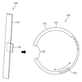
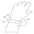
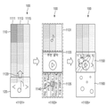
FIG. 1A shows a wearable electronic device of a first type including a plurality of displays according to one embodiment, and FIG. 1B illustrates a wearable electronic device of a second type including a plurality of displays according to an embodiment.
1A and 1B, a wearable electronic device 100 includes a wearable portion 101 that is provided to be worn on a part of a user's body, and a joint portion 103 that fixes the wearable portion 101 to a user's body ). The wearer 101 may be provided with a length greater than or equal to a predetermined size (e.g., a relatively longer length than the user's wrist) so as to be worn on, for example, the wrist of a user, Or more. The wearing portion 101 may be provided in, for example, a strap shape having a length and a width of a specified size or more. The engaging portion 103 is provided on at least one of both ends of the wearing portion 101, and both ends of the wearing portion 101 can be connected and fixed to each other. The engaging portion 103 includes a hook portion and an engaging portion provided at both ends of the wear portion 101 and the hook portion and the engaging portion are hooked to physically connect the wear portion 101, The wearer 101 may be magnetically connected to the wearer 101 including the magnetic material provided at both ends of the wearer 101. In some embodiments, the wearing portion 101 may be provided in a connected form. In this case, the engaging portion 103 may be a buckle or the like capable of adjusting the length of the wearer 101 worn according to the thickness of a part of the wearer's body.
The wearable electronic device 100 may include a plurality of displays. According to one embodiment, the wearable electronic device 100 includes a first display 110 (or main display) that forms at least a portion of the wear portion 101, and a second display 110 (or sub-display) that is slidable. The wearable electronic device 100 may be provided such that the second display 120 is slid on the rear surface of the first display 110 as shown in FIG. 1A, or the second display 120 is provided on the first display 110 as shown in FIG. (Not shown).
According to various embodiments, at least one of the first display 110 or the second display 120 may comprise a transparent display. According to one embodiment, the first display 110 comprises a transparent display and the second display 120 may comprise an organic LED (OLED) display. As another example, the first display 110 may comprise an OLED display and the second display 120 may comprise a transparent display. As another example, the first display 110 and the second display 120 may include a transparent display.
According to various embodiments, the wearable electronic device 100 may include a sliding portion in a portion of the rim of the wear portion 101. The sliding part may be provided to connect the second display 120 to the wear part 101 and slide the second display 120 on the first display 110. [ The sliding portion may include, for example, a rail provided on a side surface or a front (or rear) portion of the wearing portion 101, and a seat which is engaged with the rail and slides along the rail and on which the second display 120 is seated Section. According to one embodiment, the seat portion may be made of a transparent material.
Wearable electronic device 100 may include a processor, memory, and / or communication module. According to one embodiment, the wearable electronic device 100 may include the processor, the memory, and / or the communication module in the coupling portion 103. [ In some embodiments, the wearable electronic device 100 may further include a battery in the coupling portion 103. [
According to various embodiments, the first display 110 and the second display 120 may be electrically connected to the processor, the memory, the communication module, and the battery included in the coupling portion 103. [ According to one embodiment, the second display 120 may be electrically connected to the processor, the memory, the communication module, and the battery through wiring formed along the rails of the sliding portion. In some embodiments, the second display 120 may be coupled to the first display 110 or the processor, the memory, the communication module, and the battery via short range communication such as bluetooth. In this case, the seating part of the sliding part may further include a communication module for short-distance communication, and the second display 120 may be electrically connected to the communication module included in the seating part.
The wearable electronic device 100 may include at least one sensor. The sensor may collect a sensing value for determining a viewing area of the wearable electronic device 100, a sensing value for determining the position of the second display 120 on the first display 110, and the like. The sensor may include, for example, an acceleration sensor, a gyro sensor, a geomagnetism sensor, a Hall sensor, or an illuminance sensor. According to one embodiment, the wearable electronic device 100 may determine the field of view of the wearable electronic device 100 by analyzing the sensed values collected through at least one of the acceleration sensor, the gyro sensor, or the geomagnetic sensor. As another example, the wearable electronic device 100 may analyze the sensed values collected through at least one of the hall sensor or the illuminance sensor to determine the positional relationship between the first display 110 and the second display 120 . In some embodiments, the wearable electronic device 100 may further include a touch sensor or a reduced pressure sensor, and may detect a touch input of a user using a touch sensor or a reduced pressure sensor. In this regard, the touch sensor or the decompression sensor may be included in the first display 110 and the second display 120, and the first display 110 and the second display 120 may be fixed And a bezel region for supporting the bezel.
According to various embodiments, the wearable electronic device 100 may handle different interactions between displays depending on the view area of the wearable electronic device 100, the positional relationship between the displays, or the user input. According to one embodiment, the wearable electronic device 100 may activate a screen of a display included in a viewing area and deactivate a screen that is out of the viewing area. As another example, the wearable electronic device 100 may determine the positional relationship between the displays and adjust the transparency of the area where the screen overlaps. As another example, wearable electronic device 100 may process interactions between displays according to user input. For example, the wearable electronic device 100 may output information related to the screens of the first display 110 and the second display 120 according to a user input. In this regard, the user input may include a touch input, a bezel touch input, a sliding input, and a gesture input. In the embodiments described below, the interaction between displays is referred to as a touch interaction, a bezel touch interaction, a sliding interaction, and a gesture interaction depending on the type of user input.
FIG. 2A illustrates a gesture interaction of a wearable electronic device including a plurality of displays according to an embodiment, and FIG. 2B illustrates a sliding interaction of a wearable electronic device including a plurality of displays according to an embodiment FIG. 2C is a view for explaining a bezel touch interaction of a wearable electronic device including a plurality of displays according to an embodiment, and FIG. 2D is a view for explaining various forms of a bezel touch interaction according to an embodiment FIG.
2A, a wearable electronic device 100 may process a gesture interaction between a first display 110 and a second display 120 in response to a gesture input. According to one embodiment, the wearable electronic device 100 may receive a gesture input while wearing the wear portion 101 on a body part (e.g., a wrist) of the user. For example, a raising wrist, a turning wrist, a snapping fingers, or a wrist-waving motion may be used for the wearable electronic device 100, Shaking wrists, and so on. The wearable electronic device 100 constructs a screen related to the display object output to the first display 110 according to the received gesture input and outputs the screen to the second display 120, A screen related to the object may be configured and output to the first display 110.
According to various embodiments, the wearable electronic device 100 may activate a screen of a display contained within the field of view of the wearable electronic device 100, and deactivate the screen of the display beyond the field of view. For example, when the wearable electronic device 100 is worn by a wearer (lifting or lowering) the wrist, or when the wearer wears the wearable electronic device 100, the view area of the wearable electronic device 100 can be changed. In this case, the wearable electronic device 100 may activate or deactivate the display screen in accordance with the changed viewing area.
According to various embodiments, the wearable electronic device 100 may determine the view area of the wearable electronic device 100 at the time of wearing the wearer 101 on a portion of the body of the user, or at the time the gesture input is received . In some embodiments, the wearable electronic device 100 may determine the field of view of the wearable electronic device 100 at designated time intervals after wearing the wearable portion 101 on a portion of the user's body.
According to various embodiments, the wearable electronic device 100 may determine the view area of the wearable electronic device 100 by analyzing the sensed values collected through at least one of the acceleration sensor, the gyro sensor, or the geomagnetic sensor. According to one embodiment, the wearable electronic device 100 may determine the positional relationship between the user's gaze and the wearable electronic device 100 using at least one of the sensors described above. For example, if it is determined that the wearable electronic device 100 is worn on the wrist and the back of the user is facing the user's eyes, it can be determined that the front surface of the first display 110 is included in the viewing area. Alternatively, if it is determined that the wearer is wearing the wearable electronic device 100 and the palm is facing the user's eyes, it can be determined that the rear surface of the first display 110 is included in the view area. Alternatively, if it is determined that the user wears the wearable electronic device 100 and the hand or the palm of the hand is facing the user's eyes, it can be determined that the side of the first display 110 is included in the viewing area.
According to various embodiments, the wearable electronic device 100 may determine whether the second display 120 is included within the viewing area through a positional relationship between the first display 110 and the second display 120. According to one embodiment, the wearable electronic device 100 determines the positional relationship between the first display 110 and the second display 120 by analyzing the sensed values collected through at least one of the hall sensor or the illuminance sensor , It may determine whether the second display 120 is included within the viewing area depending on the positional relationship and which side of the first display 110 is included in the viewing area. The positional relationship between the first display 110 and the second display 120 is described in detail in FIG. 2B.
2B, the wearable electronic device 100 includes a sliding interface between the first display 110 and the second display 120 in response to an input on which the second display 110 is slid on the first display 110 Can be processed. According to one embodiment, the wearable electronic device 100 determines the positional relationship between the first display 110 and the second display 120 according to the received sliding input, To the second display 120, a screen related to the display object output in the overlapped area.
According to various embodiments, the wearable electronic device 100 can determine the positional relationship between the first display 110 and the second display 120 and adjust the transparency of the overlapped area. For example, when the second display 120 is slid on the front surface of the first display 110, if the second display 120 includes a transparent display, The transparency of the display 120 can be adjusted to a high level. Alternatively, when the second display 120 is slid on the rear surface of the first display 110, if the first display 110 includes a transparent display, The transparency of the superimposed area in the screen of the display 110 can be adjusted to be high.
According to various embodiments, the wearable electronic device 100 may analyze the sensed values collected through at least one of the hall sensor or the illuminance sensor to determine a positional relationship between the first display 110 and the second display 120 . 2B, at least one Hall sensor 130 is included in a certain area (e.g., a rail provided in a rim area) of the wearer 101 and a magnetic substance 170 ) May be included. When the second display 120 is slid, the hall sensor 130 senses the magnetic body 170 and the wearable electronic device 100 analyzes the direction and magnitude of the magnetic force obtained from the hall sensor 130, 120 can be determined. Alternatively, at least one magnetic body 170 may be included in a certain area of the wearer 101, and the hall sensor 130 may be included in the seat. In some embodiments, the wearable electronic device 100 may use a light intensity sensor instead of the Hall sensor 130 and the magnetic body 170 to determine the positional relationship between the displays. For example, the position of the second display 120 may be determined by detecting a variation in illuminance in the overlapped area between the displays according to the sliding of the second display 120. [ According to one embodiment, the illuminance sensor may be disposed on one side of the first display 110 on which the second display 120 is slid. For example, the light intensity sensor is disposed on the front surface of the first display 110 when the second display 120 is slid on the front surface of the first display 110, and the second display 120 is disposed on the front surface of the first display 110 And may be disposed on the rear surface of the first display 110 when sliding on the rear surface.
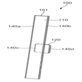
2C, the wearable electronic device 100 includes a first bezel that fixes and supports the first display 110, and a second bezel that supports and supports the second display 110, And may process the bezel touch interaction between the first display 110 and the second display 120. According to one embodiment, the wearable electronic device 100 may change the screen of the first display 110 in response to an input touching the first bezel, or change the screen associated with the display object output to the first display 110 2 display 120 and may change the screen of the second display 120 in response to an input touching the second bezel or may display a screen associated with the display object output to the second display 120 on the first display 120, (110).
According to various embodiments, the wearable electronic device 100 may sense the bezel touch input by analyzing the sensed values collected through at least one of the touch sensor and the decompression sensor. As shown in FIG. 2C, the first touch sensor 140a and the second touch sensor 140b are disposed on the left side region of the first bezel and the right side region of the first bezel, And a fourth touch sensor 140d in the right area of the second bezel. In one embodiment, the wearable electronic device 100 receives a touch input using a touch sensor or a reduced pressure sensor included in the first display 110 and the second display 120, And may process the touch interaction between the display 110 and the second display 120. For example, the wearable electronic device 100 may change the screen of the first display 110 in response to an input touching the first display 110 or may display a screen related to the display object output to the first display 110 The second display 120 may be displayed on the second display 120 by changing the screen of the second display 120 in response to an input for touching the second display 120, To the first display (110).
Referring to FIG. 2D, the wearable electronic device 100 may obtain various types of bezel touch inputs. For example, the wearable electronic device 100 may include an input for tapping either the first bezel or the second bezel as in the first state 201, an input for tapping either the first bezel or the second bezel, An input for tapping both sides of the first bezel, an input for tapping both sides of the bezel, an input for dragging one of the first bezel, as in the third state 205, an input for dragging both sides of the first bezel, Or an input to flick either of the first bezel toward the first display 110, as in the fifth state 209, or the like.
3 is a view schematically showing a configuration of a wearable electronic device according to an embodiment.
3, an electronic device 300 includes a first display 310, a second display 320, a processor 330, a sensor 340, a memory 350, and a communication interface 360 . The electronic device 300 shown in FIG. 3 may include the same or similar configuration as the wearable electronic device 100 shown in FIGS. 1A and 1B.
The first display 310 and the second display 320 may display various content (e.g., text, images, video, icons, symbols, etc.) to the user. The first display 310 or the second display 320 may be a liquid crystal display (LCD), a light-emitting diode (LED) display, an organic light emitting diode )) Display, or a microelectromechanical systems (MEMS) display, or an electronic paper display. At least one of the first display 310 or the second display 320 may include a transparent display. As another example, at least one of the first display 310 and the second display 320 may include a touch screen, for example, a touch, gesture, proximity, or hovering using an electronic pen or a user's body part hovering input.
The first display 310 and the second display 320 may include a panel and a display driver IC (DDI) configured to control the panel. For example, the first display 310 may include a first panel and a first DDI, and the second display 320 may include a second panel and a second DDI.
The first panel may have a plurality of pixels (pixels), and each pixel may include subpixels (subpixels) for displaying RGB, which is the three primary colors of light. Each of the sub-pixels includes at least one transistor, and the pixel can be adjusted according to the magnitude of the voltage (or flowing current) applied to the transistor, and the color can be expressed. The first DDI includes a gate driver circuit portion having an on / off function for controlling a gate of a sub-pixel, a source driver for adjusting a video signal of the sub- And may provide a full screen by adjusting the transistors of the sub-pixels of the first panel. The first DDI may receive the first image data from the processor 330 and operate to display the image or image on the first panel.
The second panel may have a plurality of pixels, and each pixel may include sub-pixels that display RGB, which is the three primary colors of light. Each of the sub-pixels includes at least one transistor, and the pixel can be adjusted according to the magnitude of the voltage (or flowing current) applied to the transistor, and the color can be expressed. The second DDI may include a gate driver circuit portion having an on / off function and controlling a gate of the sub-pixel, and a source driver circuit portion for adjusting a color difference by adjusting a video signal of the sub- The transistor of the pixel can be adjusted and the entire screen can be provided. The second DDI may be operable to receive second image data, which is the same or different from the first image data, from the processor 330 and display the image or image on the second panel.
According to various embodiments, at least one of the first panel or the second panel can be implemented, for example, to be flat, flexible, or bendable. At least one of the first panel or the second panel may comprise one or more modules including a touch panel and / or a pen sensor.
In embodiments implementing an electronic device 300 that includes a plurality of displays, at least some of the varying content (e.g., image data or image data stream, etc.) in the various modules and devices of the electronic device 300 Can be processed using the processor 330. [ The processor 330 may determine to output the changing content to the display of at least one of the first display 310 or the second display 320. [ For example, the first display 310 may output a command received from the communication interface 360 and the second display 320 may output a command received from the sensor 340. In another embodiment, the contents output from the first display 310 may be displayed on the screen of the second display 320 by switching or expanding the contents, or the contents output from the second display 320 may be displayed on the first display 310 You can also switch or expand on the screen.
The processor 330 may include one or more of a central processing unit (CPU), an application processor (AP), or a communication processor (CP). The processor 330 may perform computations or data processing related to, for example, control and / or communication of at least one other component of the electronic device 300.
According to various embodiments, the processor 330 may process the interplay between displays differently depending on the field of view of the electronic device 300, the positional relationship between the displays, or the user input. According to one embodiment, the processor 330 analyzes the sensed values obtained from the sensor 340 and, depending on the analyzed results, determines the field of view of the electronic device 300, the positional relationship between the displays, It can be judged. The processor 330 may activate the screen of the display included in the viewing area and deactivate the screen of the display outside the viewing area. The processor 330 may adjust the transparency of the area where the screen is superimposed according to the positional relationship between the displays. Processor 330 may change the display of displays according to the type of user input. For example, the processor 330 may change the screen of the first display 310 and / or the second display 320 according to a touch input, a bezel touch input, a sliding input, or a gesture input.
The sensor 340 may, for example, measure a physical quantity or sense the operating state of the electronic device 300 and convert the measured or sensed information into an electrical signal. According to one embodiment, the sensor 340 collects a sensing value for determining a viewing area of the electronic device 300, a sensing value for determining a positional relationship between displays, or a sensing value according to a user's input .
Memory 350 may include volatile and / or non-volatile memory. The memory 350 may store instructions or data related to at least one other component of the electronic device 300. According to one embodiment, the memory 350 may store software and / or programs.
The communication interface 360 can establish communication between the electronic device 300 and an external device. For example, the communication interface 360 may be connected to the network through wireless communication or wired communication to communicate with the external device. According to various embodiments, the communication interface 360 may be used for communication between the internal components of the electronic device 300. For example, the communication interface 360 may be used for command or data transfer between the electrically isolated second display 320 and the processor 330.
As described above, according to various embodiments, a wearable electronic device (e.g., wearable electronic device 100 or electronic device 300) includes a wearable portion (e.g., wearing portion 101) for wearing on a part of the user's body, (E.g., a first display 110 or a first display 310) that forms at least a portion of the wearer, ), A second display (e.g., a second display 120 or a second display 320) that is slid on the front or rear surface of the first display, a field of view of the wearable electronic device, At least one sensor (e.g., Hall sensor 130 or sensor 340) that senses the position of the second display, and at least one sensor included in the coupling and electrically coupled to the first display and the second display (E.g., processor 330), wherein at least one of the first display or the second display includes a transparent display, and wherein the processor is further configured to display the first display and the second display Adjusts the transparency of the area in which the first display and the second display are superimposed, and adjusts the transparency of at least one of the first display or the second display in accordance with the positional change of the second display Can be set to change.
According to various embodiments, the at least one sensor includes at least one of an acceleration sensor, a gyro sensor, or a geomagnetic sensor, and the processor analyzes the sensed value obtained from the at least one sensor, To determine the visual line of the user and the positional relationship of the wearable electronic device, and to determine the visual field based on the determined result.
According to various embodiments, the at least one sensor includes a Hall sensor, which senses a magnetic body (e.g., a magnetic body 170) included in the wearable electronic device, And to determine the position of the second display on the first display based on the result of analyzing the direction and magnitude of the magnetic force.
According to various embodiments, the Hall sensor is provided in at least one region of the wearer, and the magnetic substance may be disposed in a region where the second display is seated.
According to various embodiments, the at least one sensor comprises an illuminance sensor, the processor obtaining an illuminance value varying from the illuminance sensor according to the sliding of the second display, and based on the result of analyzing the illuminance value And to determine the position of the second display on the first display.
According to various embodiments, the illuminance sensor may be disposed on one side of the first display on which the second display is slid.
According to various embodiments, the processor may be configured to deactivate the screens of the first display and the second display beyond the field of view.
According to various embodiments, the processor adjusts the transparency of the second display to a high level when the second display is slid on the front of the first display and the second display includes a transparent display, May be set to increase the transparency of the superimposed area of the screen of the first display when the first display is slid on the rear surface of the first display and the first display includes the transparent display.
According to various embodiments, the processor may be configured to output a screen associated with the display object output to the overlapped area to the second display, corresponding to a change in the position of the second display.
According to various embodiments, a screen associated with the display object may include at least one of detailed information of the display object or additional information of the display object.
While the wearable electronic device 100 (or the electronic device 300) has been described above in terms of the positional relationship between the wearable electronic device 100 (or the electronic device 300) and the displays, ) Is the classification according to the function of the. The positional relationship between the display area and the viewing area of wearable electronic device 100 (or electronic device 300) may be changed by user input in various embodiments. For example, the field of view can be changed by the gesture input that turns the wrist, and the positional relationship between the displays can be changed by the input sliding the sub-display. In the following embodiments, description of the screen activation / deactivation function and the transparency adjustment function which can be performed according to the positional relationship between the display area and the display area of the wearable electronic device 100 may be omitted.
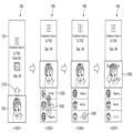
4 is a diagram for explaining a touch interaction according to an embodiment.
Referring to FIG. 4, the wearable electronic device 100 may output a screen related to a selected display object corresponding to an input that touches the first display 110 or the second display 120. The wearable electronic device 100 outputs an execution screen of a first application (e.g., a home application) to the first display 110 as in the first state 401, (For example, a clock application).
The wearable electronic device 100 is responsive to the input 420 (e.g., touching for a relatively short period of time) that taps the first display 110 as in the second state 403, The first display 110 and the second display 120 may display a screen related to the selected display object among the display objects output to the first display 110. In the drawing, an icon of a music application is selected to output an equalizer 450 to the first display 110, and a music reproduction including a reproduction pause button 431 and the like is displayed on the second display 120 And a state in which the controller 430 is outputted.
In accordance with one embodiment, the wearable electronic device 100 is capable of displaying a display object 410 output to the second display 120, corresponding to an input 440 that taps the second display 120 as in the third state 405, To the first display 110 and to the second display 120. [0033] FIG. In the drawing, a playback pause button 431 is selected to output a music list 470 to the first display 110, and a playback pause button 431 is displayed on the second display 120, 433) to indicate the output state.
5 is a diagram for explaining a combination of a touch interaction and a sliding interaction according to an embodiment.
5, the wearable electronic device 100 may output a screen associated with a selected display object corresponding to an input that touches the first display 110 or the second display 120, and the second display 120 The first display 110 and the second display 120 may display a screen related to the display object output in the area where the first display 110 and the second display 120 are overlapped. The wearable electronic device 100 outputs a first function execution screen (e.g., an equalizer) of a first application (e.g., a music playback application) to the first display 110 as in the first state 501, (E.g., a music playback controller) of the first application on the first display 120 and the second display 120. [ However, the present invention is not limited thereto. In some embodiments, an execution screen of the first application may be output to the first display 110, and an execution screen of the second application may be output to the second display 120.
The wearable electronic device 100 is responsive to an input 510 (e.g., touching over a specified time) that long tapes the second display 120 as in the second state 503, And may output a screen related to the application output to the display 120 to the first display 110. In the drawing, a list 530 of shared applications that can share currently selected (or playing) music with respect to a music playback application is displayed on the first display 110. [
According to one embodiment, when an input 520 that slides the second display 120 occurs while the long-tapping input 510 is not terminated, the wearable electronic device 100 is moved to the first display 110 The second display 120 may display a screen related to the display object output in the overlapping area of the second display 120. [ When the input 520 sliding the second display 120 and the inputting the long tap 510 are terminated, the wearable electronic device 100 displays the first display 120 at the end of the sliding of the second display 120 110 and the second display 120 are overlapped with each other. For example, the wearable electronic device 100 may share music currently selected (or playing) using a shared application output in an area where the first display 110 and the second display 120 overlap. In this case, the wearable electronic device 100 may output a screen 550 indicating that the function execution is completed, as in the third state 505, for a time designated on the second display 120.
6 is a diagram for explaining a first type of bezel touch interaction according to an embodiment.
6, the wearable electronic device 100 includes a first bezel that fixes and supports the first display 110, or a second bezel that supports and supports the second display 120, The display related to the display object output to the display on which the selected bezel is fixed and supported can be displayed. The wearable electronic device 100 may display a first function execution screen (e.g., a weather display screen over time) of a first application (e.g., a weather application) on the first display 110 as in the first state 601 And output the second function execution screen (e.g., current weather display screen) of the first application to the second display 120. [
The wearable electronic device 100 includes an input 610 (e.g., a third touch sensor 140c and a second touch sensor) that tapes both sides of a second bezel that secures and supports the second display 120, such as in a second state 603, Corresponding to the display object output to the second display 120, which is fixed and supported by the second bezel, corresponding to the input of the first display 110 and the input touching the fourth touch sensor 140d) 120). In the figure, the wearable electronic device 100 displays a detailed information screen 630 of the current weather on the first display 110. FIG.
FIG. 7 is a diagram for explaining a combination of a first type of bezel touch interaction and a sliding interaction according to an embodiment.
7, the wearable electronic device 100 includes a first bezel that fixes and supports the first display 110, or a second bezel that supports and supports the second display 120, The first display 110 and the second display 120 may overlap each other in correspondence with the input sliding the second display 120. In this case, And output a screen related to the display object output in the area. The wearable electronic device 100 displays a first function execution screen (e.g., a weather display screen over time) of a first application (e.g., weather application) on the first display 110 as in the first state 701 And output the second function execution screen (e.g., current weather display screen) of the first application to the second display 120. [
The wearable electronic device 100 may be configured to touch an input 710 (e.g., third touch sensor 140c and fourth touch sensor 140d) that taps on both sides of a second bezel that secures and supports the second display 120 The first display 110 and the second display 120 are overlapped as in the second state 703 when an input 720 that slides the second display 120 occurs while the first display 110 and the second display 120 are not terminated The second display 120 can display a screen related to the display object output in the area where the second display 120 is displayed. In the figure, the wearable electronic device 100 displays a weather-expanded screen 730 in the time zone in which the first display 110 and the second display 120 are superimposed on the second display 120 Indicates the output status.
8 is a diagram illustrating a combination of a touch interaction, a bezel touch interaction, and a sliding interaction according to an embodiment.
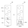
Referring to FIG. 8, the wearable electronic device 100 may output a screen related to a selected display object corresponding to an input touching the first display 110 or the second display 120, and the first display 110 Or a second bezel that fixes and supports the second display 120, and a display related to the display object output to the display fixed and supported by the selected bezel corresponding to the input to touch the second bezel And may output a screen related to the display object output in the area where the first display 110 and the second display 120 are superimposed corresponding to the input sliding the second display 120. [ The wearable electronic device 100 outputs an execution screen of a first application (e.g., an application that manages a list of applications) to the first display 110, as in the first state 801, (For example, a clock application) on the display screen of the second application. According to one embodiment, an application that manages a list of applications may sort the icons of the application according to the last execution time or the number of times the application has been executed, and output the icons to the first display 110.
The wearable electronic device 100 may respond to the input 820 that taps the first display 110 as in the second state 803 by selecting a display object from among the display objects output to the first display 110 And may output the related screen to the first display 110 and the second display 120. [ The icon 810 of the shared application is selected so that the main screen 830 of the shared application is displayed on the first display 110 and the last execution screen 840 of the shared application is displayed on the second display 120. [ (For example, a screen displaying the last activity of the user) is displayed.
According to one embodiment, the wearable electronic device 100 includes an input 850 (e.g., a third touch sensor 140c and a fourth touch) for tapping both sides of a second bezel that secures and supports the second display 120 The display related to the display object output to the second display 120 that the second bezel fixes and supports as in the third state 805 is displayed on the first display 110 As shown in Fig. In the drawing, a screen 860 is displayed on the first display 110 to display the content of the user's activity in the shared application. According to one embodiment, the screen 860 displaying the activity of the user may include a display object (e.g., bubble image, etc.) corresponding to each activity.
According to one embodiment, the wearable electronic device 100 slides the second display 120 without the input 850 tapping both sides of the second bezel fixing and supporting the second display 120, The second display 120 displays a screen related to the display object output in the overlapping area of the first display 110 and the second display 120 as in the fourth state 807, . In the figure, the activity of the user over time is displayed on the first display 110 and the activity of the user is displayed on the second display 120 in a region where the first display 110 and the second display 120 overlap And a screen 890 displaying contents that have been active in the time zone is outputted.
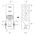
According to one embodiment, the wearable electronic device 100 includes an input 890 that double-tapes the second display 120, such as in a fifth state 809 (e.g., a two- , The display object output to the second display 120 can be transmitted to the external electronic device 800 connected to the wearable electronic device 100 via the communication interface. According to one embodiment, the external electronic device 800 may be an electronic device paired with the wearable electronic device 100.
FIG. 9 is a view for explaining a second type of bezel touch interaction according to an embodiment.
9, the wearable electronic device 100 includes a first bezel that holds and supports the first display 110, or a second bezel that supports and supports the second display 120, The execution screen of the set application can be outputted. The wearable electronic device 100 displays a first function execution screen (e.g., a weather display screen over time) of a first application (e.g., a weather application) on the first display 110 as in the first state 901 And output the second function execution screen (e.g., current weather display screen) of the first application to the second display 120. [
The wearable electronic device 100 includes an input 910 (e.g., a third touch sensor 140c) that taps on both sides of a second bezel that secures and supports the second display 120, such as in a second state 903, And the fourth touch sensor 140d for a specified time or longer), the execution screen of the application set in the first display 110 and the second display 120 can be output. In the drawing, the wearable electronic device 100 outputs an execution screen 930 of a home application including an icon 931 of applications on the first display 110, And the execution screen 950 is outputted.
10 is a view for explaining a combination of a bezel touch interaction and a sliding interaction of a second form according to an embodiment.
10, the wearable electronic device 100 includes a first bezel that holds and supports the first display 110, or a second bezel that supports and supports the second display 120, A screen related to the display object output in the area where the first display 110 and the second display 120 are overlapped corresponding to the input sliding the second display 120 can be displayed Output. The wearable electronic device 100 displays a first function execution screen (e.g., a weather display screen over time) of a first application (e.g., a weather application) on the first display 110 as in the first state 1001 And output the second function execution screen (e.g., current weather display screen) of the first application to the second display 120. [
The wearable electronic device 100 includes an input 910 (e.g., a third touch sensor 140c) that taps both sides of a second bezel that secures and supports the second display 120, as in the second state 1003, And the fourth touch sensor 140d for a specified period of time or longer) in response to the operation of the first display 110 or the second display 120. [ The drawing shows a state in which the wearable electronic device 100 outputs an execution screen 1030 of an application for managing a list of applications on the first display 110.
According to one embodiment, when an input 1020 that slides the second display 120 occurs while the long-tapping input 1010 is not terminated as in the third state 1005, the wearable electronic device 100 May output to the second display 120 a screen related to the display object output in the area where the first display 110 and the second display 120 overlap. The wearable electronic device 100 displays a preview screen 1050 of an application output to a region where the first display 110 and the second display 120 are superimposed on the list of applications on the second display 120, As shown in Fig.
According to one embodiment, when the wearable electronic device 100 is finished with the input 1020 and the long-tap input 1010 sliding the second display 120, when the sliding of the second display 120 ends The first display 110 and the second display 120 are overlapped with each other and the execution screen of the application can be output to the second display 120. [
11 to 16, which will be described later, the screen division according to the sliding interaction will be described. According to various embodiments, the wearable electronic device 100 may split the screen of the first display 110 about the location of the second display 120 in response to an input sliding the second display 120 . In addition, the wearable electronic device 100 may output an execution screen of another application to the divided screen or may output another function execution screen of the same application. In addition, the wearable electronic device 100 can control a screen output to each region corresponding to a user input generated in each divided region. 11 to 16, which will be described later, descriptions of the same or similar configurations and functions may be omitted.
FIG. 11 is a diagram for explaining screen division of a first type according to a sliding interaction according to an embodiment.
11, the wearable electronic device 100 outputs an execution screen of a first application (e.g., a life pattern display application) to the first display 110 as in the first state 1101, The execution screen of the second application (e.g., a music reproduction application) can be output to the application 120. According to one embodiment, the life pattern display application can display the display objects corresponding to the activity amount of the user, the stress index, or the usage propensity of the application on the first display 110 by area. In the figure, the amount of activity, the stress index, and the usage tendency of the application in the first region 1111, the second region 1113, and the third region 1115 are output in different colors and concentrations State.
The wearable electronic device 100 is responsive to the input 1120 sliding the second display 120 to move the first display 110 about the position of the second display 120, Can be divided into the first display area 1131, the second display area 1133, and the third display area 1135. [ The screen displayed in the first state 1101 may be displayed in a reduced size in the first display area 1131 of the first display 110. [ The second display area 1133 of the first display 110 is an area overlapped with the second display 120 and the user input generated in the second display area 1133 is an input for controlling the second display 120 Can be used. The third display area 1135 of the first display 110 may display a screen related to the application output to the first display 110 and the application output to the second display 120. [ In the drawing, the wearable electronic device 100 displays a list of recommended music in the third display area 1135 according to the user's life pattern.
According to one embodiment, the wearable electronic device 100 may be configured to display an output 1140 corresponding to the input 1140 that taps the third display area 1135, as in the third state 1105, A screen related to the selected display object among the display objects can be output. The wearable electronic device 100 outputs the detailed information screen 1150 of the selected music to the second display 120 and the image 1160 changed in accordance with the selected music in the third display area 1135, Is outputted.
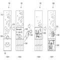
12 is a diagram for explaining a screen division of a second type according to a sliding interaction according to an embodiment.
12, the wearable electronic device 100 displays a first function execution screen (e.g., a main screen) of a first application (e.g., a shared application) on the first display 110 as in the first state 1201, And output the second function execution screen (e.g., the last execution screen) of the first application to the second display 120. [
The wearable electronic device 100 is responsive to the input 1210 sliding the second display 120 to move the first display 110 about the position of the second display 120 as in the second state 1203, Can be divided. According to one embodiment, the wearable electronic device 100 includes a first display area (e.g., a first display area 1131), a second display 120 overlapping an area where the second display 120 has not yet been slid (E.g., the second display area 1133) and the area where the second display 120 is slid and is exposed is divided into the third display area (e.g., the third display area 1135) can do.
According to an embodiment, the wearable electronic device 100 may reduce and output an existing screen displayed on the first display 110 in the first display area, And output a screen associated with at least one of the applications or the applications output to the second display 120. [ The figure shows a state in which the wearable electronic device 100 outputs a screen 1230 recommending a friend who is likely to like the screen displayed on the second display 120 in the third display area.
According to one embodiment, the wearable electronic device 100 includes an input 1240 that flickes a third display area (e.g., a finger touching a screen with a finger, Input), it is possible to scroll the screen displayed in the third display area as in the third state 1205. [
According to one embodiment, the wearable electronic device 100 may perform a function associated with a selected one of the display objects output to the third display area, corresponding to the input 1250 that taps the third display area . According to one embodiment, the wearable electronic device 100 may transmit a screen displayed on the second display 120 to a selected friend. Also, the wearable electronic device 100 may output a screen 1260 to the second display 120 indicating that the function execution is completed as in the fourth state 1207. [
FIG. 13 is a diagram for explaining a third type of screen division according to a sliding interaction according to an embodiment.
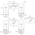
13, the wearable electronic device 100 displays a first function execution screen (e.g., an unidentified message display) of a first application (e.g., a message application) on the first display 110 as in the first state 1301 Screen) and output the second function execution screen (e.g., main screen) of the first application to the second display 120. [ According to one embodiment, the unacknowledged message display screen may display display objects 1310 (e.g., bubble images) corresponding to unread messages, sorted according to the reception time.
The wearable electronic device 100 is responsive to the input 1320 sliding the second display 120 to move the first display 110 about the position of the second display 120 as in the second state 1303, Can be divided. According to one embodiment, the wearable electronic device 100 includes a first display area (e.g., a first display area 1131), a second display 120 overlapping an area where the second display 120 has not yet been slid (E.g., the second display area 1133) and the area where the second display 120 is slid and is exposed is divided into the third display area (e.g., the third display area 1135) can do.
According to an embodiment, the wearable electronic device 100 may reduce and output an existing screen displayed on the first display 110 in the first display area, And output a screen associated with at least one of the applications or the applications output to the second display 120. [ In the drawing, the wearable electronic device 100 outputs a screen 1330 including a content of a message corresponding to a display object output in an area superimposed on the second display 120 and a reply button, And a list 1340 of friends who frequently send and receive messages to the area.
According to one embodiment, the wearable electronic device 100 may perform a function associated with the display object output in the third display area, corresponding to the gesture input 1350 that fingers the finger. According to one embodiment, the wearable electronic device 100 can deliver the message output to the second display 120 to the friends output in the third display area. At this time, the wearable electronic device 100 can change the color of each item included in the list 1330 of friends according to whether a message is sent to each friend, and output it. The drawing shows a state in which the wearable electronic device 100 outputs a screen 1360 indicating that the function execution is completed to the second display 120 as in the third state 1305.
The external electronic device 1300 receiving the message from the wearable electronic device 100 displays the display object 1370 corresponding to the message delivered to the first display 110 as in the fourth state 1307 Can be output. In addition, the external electronic device 1300 may output a screen 1390 including the contents of the message delivered to the second display 120 in response to the selection of the display object 1370 corresponding to the received message.
FIG. 14 is a diagram for explaining a fourth type screen division according to a sliding interaction according to an embodiment.
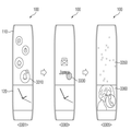
14, the wearable electronic device 100 outputs an execution screen of a first application (e.g., a health care application) to the first display 110 as in the first state 1401, 120) to the execution screen of the second application (e.g., calendar application). According to one embodiment, the healthcare application may output the display object corresponding to the user's heart rate, body fat, blood pressure, etc. to the first display 111 by region. In the drawing, the first region 1411, the second region 1413, and the third region 1415 output different heart rates, body fat, and blood pressure with different colors and concentrations.
The wearable electronic device 100 may be coupled to the first display 110 around the position of the second display 120 as in the second state 1403, corresponding to the input 1420 sliding the second display 120. [ Can be divided. According to one embodiment, the wearable electronic device 100 includes a first display area (e.g., a first display area 1131), a second display 120 overlapping an area where the second display 120 has not yet been slid (E.g., the second display area 1133) and the area where the second display 120 is slid and is exposed is divided into the third display area (e.g., the third display area 1135) can do.
According to an embodiment, the wearable electronic device 100 may reduce and output an existing screen displayed on the first display 110 in the first display area, And output a screen associated with at least one of the applications or the applications output to the second display 120. [ In the drawing, the wearable electronic device 100 outputs the user's health status screen 1430 in the time zone output in the area superimposed on the second display 120, and displays the health status of the user in the third display area : The user's heart rate, body fat, blood pressure, etc.).
According to one embodiment, the wearable electronic device 100 displays a screen associated with the display object output in the third display area, such as in the third state 1405, corresponding to the input 1450 that taps the third display area And output it to the second display 120. In the drawing, the wearable electronic device 100 displays a detailed information screen 1460 for the selected activity on the second display 120. FIG.
According to one embodiment, the wearable electronic device 100 may perform functions related to the display object output to the second display 120, corresponding to the finger-flicking gesture input 1470. According to one embodiment, the wearable electronic device 100 may register activities output to the second display 120 on a schedule. In some embodiments, the wearable electronic device 100 may store the health state of the time zone output to the overlapped area of the second display 120 in memory. The figure shows a state in which the wearable electronic device 100 outputs a screen 1480 indicating that the function execution is completed to the second display 120 as in the fourth state 1407. [ As another example, when the health state of the selected time zone is stored in the memory, the wearable electronic device 100 may initialize the health state output to the first display region and change the display object corresponding to the health state.
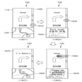
FIG. 15 is a diagram for explaining screen division according to the fifth embodiment according to the sliding interaction according to the embodiment.
Referring to FIG. 15, the wearable electronic device 100 may divide the first display 110 about the position of the second display 120, as in the first state 1501. According to one embodiment, the wearable electronic device 100 includes a first display area (e.g., a first display area 1131), a second display 120 overlapping an area where the second display 120 has not yet been slid (E.g., the second display area 1133) and the area where the second display 120 is slid and is exposed is divided into the third display area (e.g., the third display area 1135) can do.
The screen output in the first state 1501 may be the same as or similar to the screen output in the fourth state 1407 of FIG. For example, the wearable electronic device 100 outputs a display object corresponding to the health state in the first display area, outputs an activity list 1510 recommended in accordance with the health state in the third display area, A screen 1520 indicating that the function execution is completed can be output. According to one embodiment, the wearable electronic device 100 may transmit its content to the external electronic device 1500 while storing the health status in a memory or registering a recommended activity in the schedule.
According to one embodiment, when information on the health status or the recommended activity is received from the wearable electronic device 100, the external electronic device 1500 receives the notification object corresponding to the corresponding information as in the second state 1503 1530) to the first display (110). In addition, when the notification object 1530 is selected, the external electronic device 1500 outputs a screen 1550 including the contents of the notification object 1530 to the second display 120 as in the third state 1505 can do.
FIG. 16 is a diagram for explaining screen division of the sixth form according to the sliding interaction according to the embodiment.
16, the wearable electronic device 100 displays a first function execution screen (e.g., a map display screen) of a first application (e.g., navigation) on the first display 110 as in the first state 1601, And a second function execution screen (e.g., a text information display screen) of the first application can be output to the second display 120. [
The wearable electronic device 100 is responsive to the input 1610 sliding the second display 120 to move the first display 110 about the position of the second display 120 as in the second state 1603, Can be divided. According to one embodiment, the wearable electronic device 100 includes a first display area (e.g., a first display area 1131), a second display 120 overlapping an area where the second display 120 has not yet been slid (E.g., the second display area 1133) and the area where the second display 120 is slid and is exposed is divided into the third display area (e.g., the third display area 1135) can do.
According to an embodiment, the wearable electronic device 100 may reduce and output an existing screen displayed on the first display 110 in the first display area, And output a screen associated with at least one of the applications or the applications output to the second display 120. [ In the figure, a wearable electronic device 100 outputs a friend list 1620 to share position information of a user in a third display area.
According to one embodiment, the wearable electronic device 100 may perform functions related to the display object output in the third display area, corresponding to the gesture input 1630 that flicks the finger. According to one embodiment, the wearable electronic device 100 can transmit the location information of the user to the friends output in the third display area. The drawing shows a state in which the wearable electronic device 100 outputs a screen 1640 indicating that the function execution is completed to the second display 120 as in the third state 1605. [ In addition, the wearable electronic device 100 continuously displays the navigation screen 1650 for the destination in the first display area, and stores the navigation screen 1650 in the friend list 1620 according to the distance remained to the destination of the friends output in the third display area It is also possible to change the color of each item and output it.
17 to 23 to be described later, a method of providing a screen according to the bezel touch interaction will be described. According to various embodiments, the wearable electronic device 100 outputs a screen associated with the displayed display object that is adjacent to the first bezel in response to an input touching the first bezel that holds and supports the first display 110 . According to one embodiment, the wearable electronic device 100 outputs a screen related to the idle screen or the second display 120 in a widthwise (or laterally) central area of the first display 110, It is possible to output a display object corresponding to the information set in the widthwise edge area of the adjacent first display 110. As another example, the wearable electronic device 100 may set different types of objects displayed in areas adjacent to both sides of the first bezel according to the wearing direction. For example, the wearable electronic device 100 outputs a notification object, an activity history display object, or the like having a relatively high frequency of use in a region where a distance between the first bezel and the user is close to the user, You can output a simple status display object (for example, a battery remaining amount display object or a momentum display object) having a relatively low frequency of use. In FIGS. 17 to 23 described later, descriptions of the same or similar configurations and functions can be omitted.
17 is a view for explaining a method of providing a screen of a first type according to a bezel touch interaction according to an embodiment.
17, the wearable electronic device 100 outputs an idle screen in a widthwise central area of the first display 110 as in the first state 1701, and displays the idle screen in the left area of the first bezel The first display object corresponding to the first setting information (e.g., today's health state information) is output to an area adjacent to the first area (e.g., the area where the first touch sensor 140a is disposed) The second display object corresponding to at least one second setting information (e.g., notification information) in an area adjacent to the touch sensor 140b). In addition, the wearable electronic device 100 may output an execution screen of a first application (e.g., a clock application) to the second display 120. [ According to an embodiment, when the second display object corresponds to a plurality of second configuration information, the second configuration information may correspond to each second configuration information according to the time (e.g., reception time, notification time, etc.) The area of the second display object may be displayed differently. For example, in the second display object, the color of the area corresponding to each second information may be displayed differently according to the time of the second setting information.
According to one embodiment, the wearable electronic device 100 outputs first setting information to the first display 110, such as in a second state 1703, corresponding to an input 1710 that taps the first display object can do. In this case, the wearable electronic device 100 can output the same information regardless of which point of the first display object is tapped.
According to one embodiment, the wearable electronic device 100 corresponds to an input 1730 that taps the second display object such that, as in the third state 1705, the second display object has a second setting corresponding to the selected area The display object may be extended to the center area in the width direction of the first display 110 and output. In the drawing, the wearable electronic device 100 displays a state in which the selected notification object 1740 is extended to the central area of the first display 110 and output.
According to one embodiment, the wearable electronic device 100 displays, corresponding to the input 1750 dragging the second display object, a second setting information corresponding to the dragged position as in the fourth state 1707 The object can be extended to the center area in the width direction of the first display 110 and output. In this case, the wearable electronic device 100 may terminate the output of the previously-extended display object (e.g., notification object 1740).
According to one embodiment, the wearable electronic device 100 corresponds to the input 1760 flicking the extended display object, and the details of the second setting information corresponding to the extended display object as in the fifth state 1709 The information display screen 1770 can be output to the first display 110 and the function execution screen associated with the second setting information can be output to the second display 120. [ In the drawing, the wearable electronic device 100 outputs the contents of a message corresponding to an extended display object to the first display 110, and a call button capable of communicating with a user who has sent the message is displayed on a second display 120, respectively.
18 is a view for explaining a method of providing a screen of a second type according to a bezel touch interaction according to an embodiment.
18, the wearable electronic device 100 outputs a screen related to the second display 120 in the center area in the width direction of the first display 110, and corresponds to the information set in the border area adjacent to the first bezel Can be output. In the drawing, the wearable electronic device 100 outputs an execution screen of navigation in a widthwise central area of the first display 110 as in the first state 1801, and displays the execution area of the right area of the first bezel And outputs the first display object whose color is set differently according to the amount of traffic on the route to the destination in the area adjacent to the first touch sensor 140a and the second touch sensor 140b, .
According to one embodiment, the wearable electronic device 100 corresponds to the input 1810 of tapping the first display object and, as in the second state 1803, displays the setting information corresponding to the selected area of the first display object And output it to the second display 120. In the figure, the wearable electronic device 100 displays a screen 1820 including a road view and additional information (e.g. traffic volume) corresponding to a selected one of the paths to a destination on the second display 120, As shown in Fig.
According to one embodiment, the wearable electronic device 100 corresponds to the input 1830 of tapping a specific area of the first display object and, as in the third state 1805, 2 display 120 as shown in FIG. In the drawing, a state in which the wearable electronic device 100 outputs a screen 1840 including detailed information of a main point (for example, a landmark or the like) in a route to a destination to the second display 120 .
According to one embodiment, the wearable electronic device 100 may perform a function associated with the setting information corresponding to the selected area of the first display object, corresponding to the input 1850 of flicking the first display object. For example, the wearable electronic device 100 may change the selected point of the path to the destination to a new destination. In the drawing, the wearable electronic device 100 outputs a map screen 1860 showing the route to the newly changed destination, as in the fourth state 1807, to the second display 120, And a screen 1870 showing directions and the like are output to the first display 110. FIG.
19 is a view for explaining a method of providing a screen of a third form according to the bezel touch interaction according to the embodiment.
19, the wearable electronic device 100 outputs a screen related to the second display 120 in the center area in the width direction of the first display 110, and corresponds to the information set in the border area adjacent to the first bezel Can be output. In the drawing, the wearable electronic device 100 outputs the theme image corresponding to the music being played in the widthwise central region of the first display 110 as in the first state 1901, And outputs the first display object corresponding to the music list to the area adjacent to the area (for example, the area where the second touch sensor 140b is disposed) and outputs the execution screen of the music playback application to the second display 120 . According to one embodiment, the first display object may be displayed in different colors depending on the genre of music or the like. In addition, the first display object may be output in different sizes depending on the viewing frequency of each genre.
According to one embodiment, the wearable electronic device 100 corresponds to the input 1910 of tapping the first display object and, as in the second state 1903, displays the setting information corresponding to the selected region of the first display object The second display object can be extended to the center area in the width direction of the first display 110 and output. In the drawing, the wearable electronic device 100 shows a state in which the detailed information display object 1920 of the selected music is extended to the center area in the width direction of the first display 110 and output.
According to one embodiment, the wearable electronic device 100 corresponds to an input 1930 for dragging a first display object, and a third display object, which represents setting information corresponding to the selected area of the first display object, And extend to a central region in the width direction of the optical fiber 110. In this case, the wearable electronic device 100 may terminate the output of the second display object that has been previously expanded and displayed.
According to one embodiment, the wearable electronic device 100 includes an input 1940 that pinches out a particular region of a first display object, such as in a third state 1905 (e.g., An input for moving in the opposite direction to each other and then releasing the contact). In this case, the wearable electronic device 100 may extend the size 1941 of the particular region, as in the fourth state 1907.
According to one embodiment, the wearable electronic device 100 may perform a function associated with the setting information corresponding to the selected area of the first display object, corresponding to the input 1950 of flicking the first display object. In the drawing, the wearable electronic device 100 outputs the selected music playback screen 1960 to the second display 120 as in the fifth state 1909, and the theme image 1970 corresponding to the selected music, Is output to the first display 110. FIG.
20 is a view for explaining a method of providing a screen of a fourth form according to the bezel touch interaction according to the embodiment.
20, the wearable electronic device 100 outputs a screen related to the second display 120 in a widthwise central area of the first display 110, and corresponds to information set in a border area adjacent to the first bezel Can be output. The illustrated wearable electronic device 100 includes a calendar list (e.g., a first calendar 2011, a second calendar 2011, etc.) set in a widthwise central area of the first display 110, such as in the first state 2001 (E.g., a region where the second touch sensor 140b is disposed) of the first bezel based on the user's predetermined history or state or the like (E.g., a first time display object 2021, a second time display object 2023, and a second time display object) corresponding to a schedule set on the second display 120, And a third time display object 2025)
According to one embodiment, the wearable electronic device 100 corresponds to the input 2030 of tapping the first display object and, as in the second state 2003, the first display object displays the setting information corresponding to the selected area The second display object can be extended to the center area in the width direction of the first display 110 and output. In the drawing, the wearable electronic device 100 shows a state in which the selected detailed information display object 2040 is extended to the center area in the width direction of the first display 110 and output.
According to one embodiment, the wearable electronic device 100 may perform functions related to the setting information corresponding to the second display object, corresponding to the input 2050 to flick the second display object. For example, the wearable electronic device 100 may register the selected schedule on a schedule. In the figure shown, the wearable electronic device 100 displays a selected schedule (e.g., a fourth schedule 2017) on a schedule list output on the first display 110 in chronological order, such as in the third state 2005 And displays a time display object (e.g., a fourth time display object 2027) corresponding to the selected schedule on the clock screen output on the second display 120. [
According to one embodiment, the wearable electronic device 100 may change the schedule information of the dragged time display object, corresponding to the input 2060 to drag the time display object. For example, the wearable electronic device 100 may change the schedule to the time at which the time display object is dragged on the clock screen. In the figure shown, the wearable electronic device 100 has a schedule corresponding to the fourth time display object 2027, such as in the fourth state 2007, corresponding to the input to which the fourth time display object 2027 is dragged And shows the changed output status. In this case, the wearable electronic device 100 can rearrange the schedule list output to the first display 110 in chronological order according to the changed schedule.
FIG. 21 is a view for explaining a fifth method of providing a screen according to the bezel touch interaction according to the embodiment.
21, the wearable electronic device 100 outputs an idle screen in the center area in the width direction of the first display 110 and outputs a display object corresponding to the information set in the border area adjacent to the first bezel have. In the drawing, the wearable electronic device 100 outputs an idle screen in a widthwise central area of the first display 110, as in the first state 2101, and a left area of the first bezel (For example, a region in which the touch sensor 140a is disposed) and outputs a first display object in an area adjacent to the right area of the first bezel (e.g., the area where the second touch sensor 140b is disposed) And displays the execution screen of the first application (e.g., a clock application) on the second display 120. [
According to one embodiment, the wearable electronic device 100 includes a first display 210 and a second display 210, corresponding to an input 2110 for dragging a first display object and a second display object, It is possible to output a list 2120 of recommended applications based on the user's activity history in the direction central region and to output a third display object corresponding to the execution history of the recommended application in an area adjacent to the right area of the first bezel have. Also, the wearable electronic device 100 can output the execution screen 2130 of an application (e.g., a call application) having the largest execution frequency to the second display 120. [
According to one embodiment, the wearable electronic device 100 corresponds to the input 2150 tapped on the third display object, and corresponds to the setting information corresponding to the selected area of the third display object, as in the third state 2105 The corresponding fourth display object can be extended to the center area in the width direction of the first display 110 and output. In the drawing, the wearable electronic device 100 displays a state in which the icon 2160 of the selected application is extended to the center area in the width direction of the first display 110 and output.
According to one embodiment, the wearable electronic device 100 may include a fifth display object corresponding to the setting information corresponding to the dragged area of the third display object, corresponding to the input 2140 for dragging the third display object 1 display 110 in the width direction. In this case, the wearable electronic device 100 may terminate the output of the fourth display object that has been previously expanded and displayed.
According to one embodiment, the wearable electronic device 100 may perform a function associated with the fourth display object, corresponding to an input 2180 to flick a fourth display object. For example, the wearable electronic device 100 can execute the selected application and output the execution screen of the executed application to the first display 110 and the second display 120. [ In the drawing, the wearable electronic device 100 executes the selected navigation as in the fourth state 2107, outputs the map screen 2170 of the navigation execution screen to the second display 120, And a screen 2190 showing the distance and direction of the first display 110 to the first display 110. FIG.
22 is a view for explaining a method of providing a screen of a sixth form according to the bezel touch interaction according to the embodiment.
22, the wearable electronic device 100 outputs an idle screen in a center area in the width direction of the first display 110 and outputs a display object corresponding to information set in a border area adjacent to the first bezel have. In the drawing, the wearable electronic device 100 outputs an idle screen in a widthwise central area of the first display 110, as in the first state 2101, and a left area of the first bezel (For example, a region in which the touch sensor 140a is disposed) and outputs a first display object in an area adjacent to the right area of the first bezel (e.g., the area where the second touch sensor 140b is disposed) And displays the execution screen of the first application (e.g., a clock application) on the second display 120. [
According to one embodiment, when the wearable electronic device 100 generates an input 2210 that taps the first display 110 while the idle screen is output, the wearable electronic device 100 displays the first display 110 as in the second state 2202 110 in the widthwise central region of the screen. In the drawing, a wearable electronic device 100 outputs a home screen 2220 in a widthwise central region of the first display 110. [
According to an exemplary embodiment, when an input 2230 that taps the first display 110 occurs while a set screen is being output, the wearable electronic device 100 displays the set screen as in the third state 2203 And perform functions related to the selected display object among the included display objects. For example, the wearable electronic device 100 executes an application corresponding to the selected icon among the icons of the application included in the home screen 2220, and displays the execution screen of the application on the first display 110 and the second display 120, . In the drawing, the wearable electronic device 100 executes the selected navigation, outputs the map screen 2250 of the navigation execution screen to the second display 120, and displays a screen showing the distance and direction to the destination 2240 are output to the first display 110. FIG. In addition, the wearable electronic device 100 may change the first display object and the second display object into a display object associated with the executed application. For example, the wearable electronic device 100 may terminate the output of the first display object and change the second display object to a third display object whose color is set differently according to the amount of traffic, to the destination.
According to one embodiment, the wearable electronic device 100 terminates the output of the third display object, as in the fourth state 2204, corresponding to the input 2260 dragging the first bezel, And output the second display object. For example, the wearable electronic device 100 may output a first display object indicating a remaining battery level and a second display object corresponding to notification information.
According to one embodiment, the wearable electronic device 100 corresponds to the input 2270 of tapping the second display object, the fourth display object corresponding to the setting information corresponding to the selected area of the second display object, And extend to the central area of the display 110 in the width direction. In the drawing, the wearable electronic device 100 extends the icon 2280 of the message application corresponding to the message notification information selected as in the fifth state 2205 to the widthwise central region of the first display 110 Indicates the output status.
According to one embodiment, the wearable electronic device 100 may perform a function associated with the fourth display object, corresponding to an input 2290 to flick a fourth display object. For example, the wearable electronic device 100 may execute an application corresponding to the selected notification information, output an execution screen of the executed application to the first display 110, and transmit an application related to the executed application to the second display 120 As shown in Fig. In the drawing, the wearable electronic device 100 executes a message application as in the sixth state 2206, outputs an execution screen 2291 of the message application to the first display 110, And the execution screen 2293 of the call application is output to the second display 120. FIG.
FIG. 23 is a view for explaining a seventh aspect of a screen providing method according to the bezel touch interaction according to the embodiment.
23, the wearable electronic device 100 outputs an idle screen in the center area in the width direction of the first display 110 and outputs a display object corresponding to information set in a border area adjacent to the first bezel have. In the drawing, the wearable electronic device 100 outputs an idle screen in a widthwise central area of the first display 110, as in the first state 2301, and the left area of the first bezel (For example, a region in which the touch sensor 140a is disposed) and outputs a first display object in an area adjacent to the right area of the first bezel (e.g., the area where the second touch sensor 140b is disposed) And displays the execution screen of the first application (e.g., a clock application) on the second display 120. [
According to one embodiment, when the wearable electronic device 100 generates an input 2310 that taps the first display 110 in a state in which the idle screen is output, the wearable electronic device 100 displays the first display 110 as in the second state 2303 110 in the widthwise central region of the screen. In the drawing, a wearable electronic device 100 outputs a home screen 2320 in a widthwise central region of the first display 110. [
According to one embodiment, when the input 2330 that taps the first display 110 occurs while the set screen is being output, the wearable electronic device 100 displays the set screen as shown in the third state 2305 And perform functions related to the selected display object among the included display objects. For example, the wearable electronic device 100 executes an application corresponding to the selected icon among the icons of the application included in the home screen 2320, and displays the execution screen of the application on the first display 110 and the second display 120, . In the drawing, the wearable electronic device 100 executes the selected navigation, outputs the map screen 2350 of the navigation execution screen to the second display 120, and displays a screen showing the distance to the destination, 2340 are output to the first display 110. FIG.
According to one embodiment, the wearable electronic device 100 outputs a screen set in a central area of the first display 110, such as in a fourth state 2307, corresponding to an input 2360 tapping the first bezel can do. In the drawing, the wearable electronic device 100 displays a home screen in a central area of the first display 110. [
24 to 29, which will be described later, a method of providing a screen according to a sliding interaction will be described. According to various embodiments, the wearable electronic device 100 may be associated with a display object that is output in a region where the first display 110 and the second display 120 overlap the corresponding input that slides the second display 120 Screen can be output. 24 to 29, which will be described later, descriptions of the same or similar configurations and functions can be omitted.
24 is a view for explaining a method of providing a first type of screen according to the sliding interaction according to the embodiment.
24, the wearable electronic device 100 outputs an execution screen of a first application (e.g., a photo file management application) to the first display 110, as in the first state 2401, The execution screen of the second application (e.g., a clock application) can be output to the display 120. [ According to one embodiment, the photo file management application can support the function of outputting and deleting photo files as an application for supporting photo files stored in the memory. In the drawing, a wearable electronic device 100 randomly outputs a display object 2410 corresponding to a photo file to the first display 110. [
According to one embodiment, the wearable electronic device 100 moves the randomly displayed display object 2410 in a second state 2403 at a point in time when an input 2420 that slides the second display 120 occurs The information can be sorted according to the set information (e.g., stored time or stored location (or folder)). The figure shows a state in which the wearable electronic device 100 outputs a screen 2430 on which the display objects 2410 corresponding to the photo files are arranged on the first display 110 in the order of time in which the photo files are stored. According to one embodiment, the wearable electronic device 100 may group photo files stored at the same or similar time and output them as abstract figures.
According to one embodiment, the wearable electronic device 100 may be configured such that when the input 2420 that slides the second display 120 continues, the first of the display objects 2410 output to the first display 110 110 and the second display 120 may be output to the second display 120. In this case, In the drawing, the wearable electronic device 100 outputs an output screen 2440 of a photo file corresponding to a display object output to the overlapped area as in the third state 2405 to the second display 120 State. In some embodiments, the wearable electronic device 100 may output to the second display 120 an output screen of the first picture file among the group-specific picture files corresponding to the abstract figure output in the overlapped area.
According to one embodiment, the wearable electronic device 100 displays a screen associated with the display object output to the second display 120, corresponding to the input 2450 flicking the second display 120, As shown in Fig. In the drawing, the wearable electronic device 100 displays an output screen 2460 of a photo file associated with a photo file output to the second display 120, as in the fourth state 2407, on the second display 120 Indicates the output status. In some embodiments, the wearable electronic device 100 may display the output picture of the previous picture file or the next picture file on the second display 120 (if the picture file output on the second display 120 is one of the picture files per group) ).
25 is a view for explaining a method of providing a screen of a second type according to a sliding interaction according to an embodiment.
Referring to Figure 25, the wearable electronic device 100 outputs a standby screen to the first display 110, as in the first state 2501, and a first application (e.g., The status display application of the status display application). According to one embodiment, the user's status display application may be an application that displays the user's current status and preferences.
According to one embodiment, the wearable electronic device 100 may be configured to provide the wearable electronic device 100 with the output of the second display 120, such as in the second state 2503, The first display 110 may output a list 2520 of applications arranged according to information related to the display object. In the drawing, the wearable electronic device 100 outputs a list 2520 of applications sorted according to the current state of the user to the first display 110. As another example, the wearable electronic device 100 may symbolically output the list 2520 of applications. In this regard, the application list 2520 may include a music playback application configured to run music that matches the current state of the user, a healthcare application that recommends food and exercise to suit the health state of the user, Navigation to guide possible destinations (e.g., parks, restaurants, etc.), and the like.
According to one embodiment, the wearable electronic device 100 is able to display the first display 110 and the second display 120 of the list 2520 of applications when the input 2510 that slides the second display 120 continues, To the first display 110, a screen related to the application output in the overlapped area. In the figure, the application-specific recommendation items 2530 output to the overlapped area as in the third state 2505 are output to the first display 110. [
According to one embodiment, when the wearable electronic device 100 is finished with the input 2510 sliding the second display 120, the first display 110 and the second display 250 of the application-specific recommendation items 2530 120 may perform functions related to the items output in the overlapped area. In the drawing, the wearable electronic device 100 executes an application corresponding to a selected item among the recommendation items 2530 as in the fourth state 2507, and executes the execution screen 2540 of the executed application on the second And outputs it to the display 120. Fig.
26 is a view for explaining a method of providing a screen of a third form according to the sliding interaction according to the embodiment.
Referring to Figure 26, the wearable electronic device 100 outputs a standby screen to the first display 110, as in the first state 2601, and displays a standby screen on the second display 120, Application) can be outputted. According to one embodiment, the wearable electronic device 100 may output a display object 2610 corresponding to various kinds of notification information on a standby screen. As another example, the wearable electronic device 100 may apply the moving effect in the idle screen by continuously changing the position of the display object 2610 or the like.
According to one embodiment, the wearable electronic device 100 includes an input 2620 (e.g., a third touch sensor 140c and a fourth touch) for tapping both sides of a second bezel that secures and supports the second display 120, The display object 2610 output to the first display 110 as in the second state 2602 may be sorted and output according to the set information corresponding to the input to which the sensor 140d is touched. As an example, the wearable electronic device 100 may arrange the display object 2610 according to the time of the notification information (e.g., the reception time or the notification time, etc.).
According to one embodiment, the wearable electronic device 100 includes a display object 2602 corresponding to the input 2630 that slides the second display 120, The second display 120 may display a screen related to the display object output in the area where the first display 110 and the second display 120 overlap. The drawing shows a state in which the detail information screen 2640 of the notification information corresponding to the display object output in the overlapped area of the wearable electronic device 100 is output to the second display 120. [
According to one embodiment, the wearable electronic device 100 may perform functions related to the display object output to the second display 120, corresponding to the input 2651 that taps the second display 120. [ In the drawing, the wearable electronic device 100 registers the first time display object 2661 corresponding to the first notification information on the clock screen as in the fourth state 2604 and outputs it to the second display 120 State. Similarly, when the wearable electronic device 100 slides the second display 120 as in the fifth state 2605 and the detailed information screen of the second announcement information is output to the second display 120, When the input 2653 for tapping the second display 120 is generated, the second time display object corresponding to the second notification information may be registered on the clock screen.
According to one embodiment, when the wearable electronic device 100 is returned to its original position as in the sixth state 2606, when an input 2670 that slides the second display 120 occurs and the second display 120 returns, The time display object corresponding to the notification information registered on the clock screen can be output to the second display 120. [ In the drawing, the wearable electronic device 100 outputs a clock screen on which the third time display object 2681 and the fourth time display object 2683 are registered, to the second display 120.
FIG. 27 is a view for explaining a method of providing a screen of a fourth form according to the sliding interaction according to the embodiment.
27, the wearable electronic device 100 may output a display object 2710 in which the notification information is linearly symbolized on the first display 110, as in the first state 2701. [ As another example, the wearable electronic device 100 may sort and output the display object 2710 according to the time (e.g., reception time) of the notification information corresponding to the display object 2710. [ As another example, the wearable electronic device 100 may output the color of the display object 2710 differently according to the type of application that can output the notification information.
According to one embodiment, the wearable electronic device 100 includes a display object 2702 corresponding to an input 2720 that slides the second display 120, The second display 120 may display a screen related to the display object output in the area where the first display 110 and the second display 120 overlap. In the drawing, an application capable of outputting the first notification information corresponding to the first display object output to the overlapping area of the wearable electronic device 100 is executed, and an execution screen 2730 of the executed application is displayed 2 display (120). Similarly, when the wearable electronic device 100 slides the second display 120 as in the third state 2705 and the second display object is located in the overlapped area, the wearable electronic device 100 displays the second notification corresponding to the second display object It is possible to execute an application capable of outputting information and to output an execution screen 2750 of the executed application to the second display 120. [
FIG. 28 is a view for explaining a fifth-type screen providing method according to the sliding interaction according to the embodiment.
28, the wearable electronic device 100 may output a display object 2810 that symbolizes notification information to the first display 110, as in the first state 2801. [ As another example, the wearable electronic device 100 may sort and output the display object 2810 according to the time (e.g., reception time) of the notification information corresponding to the display object 2810. [ As another example, the wearable electronic device 100 may output the shape of the display object 2810 differently according to the kind of the announcement information.
In accordance with one embodiment, the wearable electronic device 100 is configured to display a display object 282 corresponding to an input 2820 that slides the second display 120, such as in a second state 2803, The second display 120 may display a screen related to the display object output in the area where the first display 110 and the second display 120 overlap. In the drawing, an application capable of outputting notification information corresponding to a display object output in the overlapping area of the wearable electronic device 100 is executed, and an execution screen 2830 of the executed application is displayed on the second display 120 ). ≪ / RTI >
FIG. 29 is a view for explaining a method of providing a screen of a sixth form according to the sliding interaction according to the embodiment.
Referring to FIG. 29, the wearable electronic device 100 may output a display object in which a function having a high frequency of use is symbolized as a graphic in the first display 110, as in the first state 2901.
According to one embodiment, the wearable electronic device 100 corresponds to the input 2910 flicking the second display 120, and in response to the first 2903 output from the first display 120, The first display 110 may output a second display object 2920 in which a first function related to the display object is symbolized in a graphic form.
In accordance with one embodiment, the wearable electronic device 100 is configured to respond to an input 2930 that slides the second display 120 such that the display object < RTI ID = 0.0 > To the second display 120, a screen related to the display object output in the area where the first display 110 and the second display 120 are overlapped. In the drawing, the wearable electronic device 100 executes a second function corresponding to the third display object output in the overlapped area, and outputs the second function execution screen 2940 to the second display 120 State. Similarly, when the wearable electronic device 100 slides the second display 120, as in the fourth state 2907, and the second display object 2920 is located in the overlapped area, the second display object 2920, And the first function execution screen 2950 can be output to the second display 120. [0213]
30 to 35, which will be described later, a method of providing a screen according to a gesture interaction will be described. According to various embodiments, the wearable electronic device 100 may output to the second display 120 a screen associated with the display object output to the first display 110 in response to the gesture input, And output the screen related to the output display object to the first display 110. [ 30 to 35, which will be described later, descriptions of the same or similar configurations and functions can be omitted.
FIG. 30 is a view for explaining a first-type screen providing method according to the gesture interaction according to the embodiment.
Referring to Figure 30, the wearable electronic device 100 outputs a standby screen to the first display 110, as in the first state 3001, and a second application, such as a clock Application) can be outputted.
According to one embodiment, the wearable electronic device 100 corresponds to a gesture input 3010 that lifts the wrist wearing the wearable electronic device 100, and as shown in the second state 3002, (Or unread) first notification information on the screen 3020. [0154] FIG. When the gesture input 3030 that wobbles the wrist is generated in a state in which the screen 3020 displaying the unconfirmed first notification information is output, the wearable electronic device 100 displays an unidentified The first display 110 may display a screen 3040 for displaying the second notification information. Likewise, when the wearable electronic device 100 generates the gesture input 3050 that shakes the wrist in a state in which the screen 3040 displaying the unconfirmed second alert information is output, The third display information 3060 may be displayed on the first display 110. [
According to one embodiment, the wearable electronic device 100 corresponds to a gesture input 3070 that turns a wrist, and displays a screen associated with the display object output to the first display 110, such as in the fifth state 3005, 2 display 120 as shown in FIG. The figure shows a state in which the wearable electronic device 100 outputs a screen 3080 including a call button that allows the wearable electronic device 100 to talk to the other party in relation to a missed call on the second display 120. [ In addition, when the wearable electronic device 100 receives an input for selecting the call button, the wearable electronic device 100 can perform a call function as in the sixth state 3006. [
31 is a diagram for explaining a method of providing a screen of a second form according to an embodiment of gesture interaction.
31, the wearable electronic device 100 outputs an execution screen of a first application (e.g., a message application) to the first display 110, as in the first state 3101, 120) of the second application (e.g., a clock application).
According to one embodiment, the wearable electronic device 100 corresponds to a gesture input 3110 that rotates the wrist wearing the wearable electronic device 100, and is coupled to the first display 110 as in the second state 3103 And output the screen related to the output display object to the second display 120. [ The figure shows a state in which the wearable electronic device 100 outputs a detailed information screen 3120 of a message output to the first display 110 to the second display 120. [
According to one embodiment, the wearable electronic device 100 is configured such that when a gesture input 3130 that maintains the wrist rotation state is generated after a gesture input 3110 that turns a wrist occurs, 2 screen 3120 displayed on the display 120 can be scrolled (step 3140). In addition, when the wearable electronic device 100 scrolls to the end of the screen 3120 output to the second display 120 after the rotation of the wrist is maintained, The second display 120 may display a screen including a call button 3150 and a reply button 3160 for the message.
FIG. 32 is a view for explaining a method of providing a screen of a third form according to the gesture interaction according to an embodiment.
Referring to FIG. 32, the wearable electronic device 100 may transmit a display object output to the first display 110 to the wearable electronic device 100 in response to a gesture input to an external electronic device connected through a communication interface. The wearable electronic device 100 outputs a first image 3210 to the first display 110 and a first application (e.g., a clock application) to the second display 120, as in the first state 3201, Can be displayed.
According to one embodiment, the wearable electronic device 100 is configured to move the display object output to the first display 110 to the outside of the wearable electronic device 100, corresponding to the gesture input 3220, And transmitted to an electronic device. In the figure shown, the wearable electronic device 100 transmits a first image 3210 to an external electronic device and outputs a transmission completion screen 3230 to the second display 120, as in the second state 3203 State.
FIG. 33 is a view for explaining a method of providing a screen of a fourth form according to the gesture interaction according to the embodiment. FIG. The wearable electronic device 100 in Fig. 33 may correspond to the external electronic device in Fig. For example, in FIG. 32, the wearable electronic device 100 may transmit the first image 3210 to the wearable electronic device 100 in FIG. 33 in response to the gesture input.
33, a wearable electronic device 100 may receive a display object (e.g., a first image 3210) from an external electronic device (e.g., wearable electronic device 100 of FIG. 32). When the wearable electronic device 100 receives the display object from the external electronic device, it may output the notification object 3310 informing the first display 110 of reception of the display object as in the first state 3301. [
In accordance with one embodiment, the wearable electronic device 100 may display a detailed information screen of the notification object 3310 on the first display 110, as in the second state 3303, corresponding to the selection of the notification object 3310 Can be output. The wearable electronic device 100 also displays a display object 3310 corresponding to the notification object 3310 on the first display 110 as in the third state 3305 corresponding to the input 3330 tapping the detailed information screen For example, a first image 3210), and a call button 3360 that allows the second display 110 to communicate with the party that transmitted the display object. According to one embodiment, when the wearable electronic device 100 receives a display object (e.g., a first image 3210) from an external electronic device, the wearable electronic device 100 reconfigures the display object to correspond to the screen of the wearable electronic device 100 And output a display object (e.g., second image 3350). For example, the wearable electronic device 100 may output, to the first display 110, a second image 3350 that has changed the size of the first image 3210 or the like so as to correspond to the resolution of the screen or the like.
FIG. 34 is a diagram for explaining a method of providing a screen of a fifth form according to the gesture interaction according to the embodiment. FIG.
34, the wearable electronic device 100 displays contents corresponding to the display object output to the first display 110 corresponding to the gesture input and the application running on the second display 120 to the wearable electronic device 100, To an external electronic device connected through a communication interface. The wearable electronic device 100 outputs a first image 3410 to the first display 110 and outputs an execution screen 3420 of a first application (e.g., a music playback application) to the second display 120 can do. According to one embodiment, the first image 3410 may be an image that changes according to the music currently being played.
According to one embodiment, the wearable electronic device 100 includes a first image 1102 output to the first display 110, corresponding to a gesture input 3430 that flips a finger of a hand wearing the wearable electronic device 100, 3410) and content associated with an application running on the second display 120 (e.g., a currently playing music file) to an external electronic device. The drawing shows a state in which the wearable electronic device 100 outputs the transmission completion screen 3480 to the second display 120. [
FIG. 35 is a view for explaining a sixth aspect of the screen providing method according to the gesture interaction according to the embodiment. FIG. The wearable electronic device 100 in Fig. 35 may correspond to the external electronic device in Fig. For example, in FIG. 34, the wearable electronic device 100 may transmit the first image 3410 and the content to the wearable electronic device 100 in FIG. 35 corresponding to the gesture input.
35, the wearable electronic device 100 is configured to receive a display object (e.g., a first image 3410) and content (e.g., currently playing) from an external electronic device (e.g., wearable electronic device 100 of FIG. 34) Music file) can be received. When the wearable electronic device 100 receives the display object and the content from the external electronic device, the wearable electronic device 100 outputs a notification object 3510 informing reception of the display object and the content to the first display 110 as in the first state 3501 can do.
In accordance with one embodiment, the wearable electronic device 100 is configured to display a detailed information screen of the notification object 3510 on the first display 110, as in the second state 3503, corresponding to the selection of the notification object 3510 Can be output. In addition, the wearable electronic device 100 executes an application capable of executing the received content, such as in the third state 3505, corresponding to the input 3530 of tapping the detailed information screen, (E.g., a first image 3410) to the first display 120. The first display 3410 may display the first display image 3540 on the first display 120 with the received display object (e.g., the first image 3410). In addition, the wearable electronic device 100 may display a display 3550 including a display button and a call button that allows the wearer to communicate with the second display 110,
36 shows a method of operating a wearable electronic device according to a method of providing a screen according to an embodiment.
Referring to FIG. 36, at operation 3610, a wearable electronic device (e.g., wearable electronic device 100) may determine a field of view. According to one embodiment, the wearable electronic device can analyze the sensed values collected through at least one of the acceleration sensor, the gyro sensor, or the supportive sensor to determine the field of view of the wearable electronic device.
At operation 3630, the wearable electronic device may activate a screen of the viewing area. According to one embodiment, the wearable electronic device may activate a screen of displays contained within a viewing area. In some embodiments, the wearable electronic device may deactivate the display of displays beyond the viewing area.
At operation 3650, the wearable electronic device may sense the position of the second display (e.g., the second display 120) on the first display (e.g., first display 110). According to one embodiment, the wearable electronic device may analyze the sensed values collected through at least one of the hall sensor or the illuminance sensor to determine the position of the second display on the first display. As another example, the wearable electronic device can determine the overlapped area according to the positional relationship between the first display and the second display.
At operation 3670, the wearable electronic device may adjust the transparency of the overlapping area of the first display and the second display. According to one embodiment, the wearable electronic device is configured to display the transparency of the second display such that when the second display is slid on the front surface of the first display, the second display includes a transparent display, Can be adjusted high. Alternatively, the wearable electronic device may be arranged such that when the second display is slid on the rear surface of the first display, if the first display includes a transparent display, The transparency can be adjusted to a high level.
At action 3690, the wearable electronic device may change the screen in response to a change in position of the second display. According to one embodiment, the wearable electronic device may output to the second display a screen related to the display object output in the overlapping area of the first display and the second display, corresponding to the input sliding the second display. For example, the wearable electronic device may output a screen including at least one of the detailed information of the display object and the additional information of the display object to the second display. However, the present invention is not limited thereto. According to various embodiments, the wearable electronic device may handle touch interaction, bezel touch interaction, and gesture interaction as well as sliding interaction. For example, a wearable electronic device may include an input for touching a first display or a second display, an input for touching a first bezel that holds and supports a first display, an input that touches a second bezel that holds and supports a second display, Or gesture input of the first display or the second display in response to at least one of the first display or the second display.
As described above, according to various embodiments, the display device includes a second display (e.g., a second display 120) that is slid on the front or back of the first display (e.g., the first display 110) A method of providing a screen of a wearable electronic device (e.g., a wearable electronic device (100)) in which at least one of the display or the second display includes a transparent display includes determining an area of view of the wearable electronic device, The method comprising: activating a screen of the first display and the second display, sensing a position of the second display on the first display, and displaying the transparency of the area where the first display and the second display overlap And a second display, wherein the first display or the second display And changing an image of at least one of the splay.
According to various embodiments, the act of determining the field of view includes obtaining a sensed value from at least one of an acceleration sensor, a gyro sensor, or a geomagnetic sensor included in the wearable electronic device, Determining a positional relationship between the user's gaze and the wearable electronic device, and determining the visual field based on the positional relationship.
According to various embodiments, the act of sensing the position of the second display on the first display is dependent on the sliding of the second display from a hall sensor (e.g., hall sensor 130) included in the wearable electronic device Obtaining an orientation and size of the varying magnetic force, and determining the position of the second display on the first display based on a result of analyzing the direction and magnitude of the magnetic force.
According to various embodiments, the act of sensing the position of the second display on the first display includes obtaining an illuminance value varying with the sliding of the second display from an illuminance sensor included in the wearable electronic device, And determining the position of the second display on the first display based on the result of analyzing the illuminance value.
According to various embodiments, the method of providing a screen may further include inactivating a screen of the first display and the second display outside the viewing area.
According to various embodiments, the act of adjusting the transparency of the superimposed area may be such that when the second display is slid on the face of the first display and the second display comprises a transparent display, And adjusting the degree of transparency of the superimposed area of the screen of the first display to a high level when the second display is slid on the rear surface of the first display and the first display includes a transparent display . ≪ / RTI >
According to various embodiments, the operation of changing the at least one screen includes outputting a screen related to the display object output to the overlapped area to the second display in response to the change of the position of the second display can do.
According to various embodiments, the operation of outputting to the second display may include outputting a screen including at least one of the detailed information of the display object or the additional information of the display object to the second display.
In the above-described embodiments, the wearable electronic device can select different information to be output depending on whether the first display or the second display is transparent when changing the screen of the first display or the second display. For example, when the first display or the second display includes a transparent display, the resolution may be lower than when the first display or the second display does not include a transparent display. Accordingly, the wearable electronic device outputs more brief information (e.g., icons, symbols, etc.) when it includes a transparent display and outputs more detailed information (e.g., text, etc.) desirable.
According to one embodiment, when the first display includes a transparent display and the second display does not include a transparent display and is slid on the back surface of the first display, the overlapped area of the first display includes brief information And detailed information may be output to the second display. For example, when the wearable electronic device receives a message, the wearable electronic device outputs a notification image informing reception of the message to the first display, and outputs the text corresponding to the message content to the second display when the notification image is selected. In yet another embodiment, when the second display includes a transparent display and the second display does not include a transparent display and is slid on the top surface of the first display, brief information is output to the second display, Detailed information may be output to the first display. For example, the wearable electronic device may output a notification image informing the reception of the message to the second display, and output the text corresponding to the message content to the first display when the notification image is selected. As another example, when the notification image is selected, the wearable electronic device can increase the transparency of the display on which the notification image is output or end the output of the notification image to control the text corresponding to the contents of the message to be clearly visible .
As used in this document, the term "module" may refer to a unit comprising, for example, one or a combination of two or more of hardware, software or firmware. A "module" may be interchangeably used with terms such as, for example, unit, logic, logical block, component, or circuit. A "module" may be a minimum unit or a portion of an integrally constructed component. A "module" may be a minimum unit or a portion thereof that performs one or more functions. "Modules" may be implemented either mechanically or electronically. For example, a "module" may be an application-specific integrated circuit (ASIC) chip, field-programmable gate arrays (FPGAs) or programmable-logic devices And may include at least one.
At least a portion of a device (e.g., modules or functions thereof) or a method (e.g., operations) according to various embodiments may include, for example, computer-readable storage media in the form of program modules, As shown in FIG. When the instruction is executed by a processor (e.g., processor 330), the one or more processors may perform a function corresponding to the instruction. The computer-readable storage medium may be, for example, memory 350. [
The computer-readable recording medium may be a hard disk, a floppy disk, a magnetic media such as a magnetic tape, an optical media such as a CD-ROM, a DVD (Digital Versatile Disc) May include magneto-optical media (e.g., a floppy disk), a hardware device (e.g., ROM, RAM, or flash memory, etc.) Etc. The hardware devices described above may be configured to operate as one or more software modules to perform the operations of the various embodiments. And vice versa.
Modules or program modules according to various embodiments may include at least one or more of the elements described above, some of which may be omitted, or may further include additional other elements. Operations performed by modules, program modules, or other components in accordance with various embodiments may be performed in a sequential, parallel, iterative, or heuristic manner. Also, some operations may be performed in a different order, omitted, or other operations may be added.
And the embodiments disclosed in this document are provided for the explanation and understanding of the disclosed technical contents, and do not limit the scope of the present invention. Accordingly, the scope of this document should be interpreted to include all modifications based on the technical idea of the present invention or various other embodiments.