KR20170096476A - Touch Pressure Sensor for Touch Screen Panel and Touch Screen Panel comprising the Touch Pressure Sensor - Google Patents
Touch Pressure Sensor for Touch Screen Panel and Touch Screen Panel comprising the Touch Pressure Sensor Download PDFInfo
- Publication number
- KR20170096476A KR20170096476A KR1020160017899A KR20160017899A KR20170096476A KR 20170096476 A KR20170096476 A KR 20170096476A KR 1020160017899 A KR1020160017899 A KR 1020160017899A KR 20160017899 A KR20160017899 A KR 20160017899A KR 20170096476 A KR20170096476 A KR 20170096476A
- Authority
- KR
- South Korea
- Prior art keywords
- touch
- electrode
- sensing
- disposed
- substrate
- Prior art date
Links
Images


Classifications
-
- G—PHYSICS
- G06—COMPUTING; CALCULATING OR COUNTING
- G06F—ELECTRIC DIGITAL DATA PROCESSING
- G06F3/00—Input arrangements for transferring data to be processed into a form capable of being handled by the computer; Output arrangements for transferring data from processing unit to output unit, e.g. interface arrangements
- G06F3/01—Input arrangements or combined input and output arrangements for interaction between user and computer
- G06F3/03—Arrangements for converting the position or the displacement of a member into a coded form
- G06F3/041—Digitisers, e.g. for touch screens or touch pads, characterised by the transducing means
- G06F3/0414—Digitisers, e.g. for touch screens or touch pads, characterised by the transducing means using force sensing means to determine a position
-
- G—PHYSICS
- G06—COMPUTING; CALCULATING OR COUNTING
- G06F—ELECTRIC DIGITAL DATA PROCESSING
- G06F2203/00—Indexing scheme relating to G06F3/00 - G06F3/048
- G06F2203/041—Indexing scheme relating to G06F3/041 - G06F3/045
- G06F2203/04103—Manufacturing, i.e. details related to manufacturing processes specially suited for touch sensitive devices
Abstract
Description
BACKGROUND OF THE INVENTION 1. Field of the Invention [0001] The present invention relates to a touch pressure sensing sensor and a method of manufacturing the touch pressure sensing sensor, and more particularly, to a touch sensor which is mounted on a transparent adhesive layer of a touch screen panel.
Generally, a touch screen panel is manufactured by attaching a touch sensor having a transparent electrode to a transparent glass to a cover glass.
The touch screen panel senses a touch on the screen in a capacitive manner using the touch sensor.
In addition, the touch screen panel senses two-dimensional sensing by the touch sensor, that is, sensing of the touch on the plane of the screen and only the position on the detected plane.
Accordingly, a touch pressure sensing sensor for a touch screen panel has been proposed in which a touch pressure is sensed to satisfy various demands of a user and the installed program or application is separately executed according to the touch pressure.
The touch pressure sensor for a touch screen panel is typically disposed on the lower side of the display panel unit and senses the pressure applied from the cover substrate of the touch screen panel through the display panel unit.
The conventional touch pressure sensor for a touch screen panel has electrodes for generating capacitance change values or resistance change values separately on the upper and lower sides and electrodes on the upper and lower surfaces of the elastic supporter There is a problem that the thickness is increased because the substrate is provided.
The conventional touch screen panel to which the touch pressure sensor for a touch screen panel is applied has a problem in that the thickness and the weight of the touch screen panel are increased by disposing the touch pressure sensor for the touch screen panel on the lower side of the display panel unit.
SUMMARY OF THE INVENTION The present invention has been made in view of the above-mentioned problems, and it is an object of the present invention to provide a light and slim touch pressure sensor provided in a transparent adhesive layer between a cover substrate of a touch screen panel and a display panel unit, .
According to an aspect of the present invention, there is provided a touch pressure sensor including a transparent adhesive layer disposed between a cover substrate of a touch screen panel and a display panel unit, an elastic supporter adhered to the transparent adhesive layer, A first electrode member for pressure sensing disposed on the upper side, and a second electrode member for pressure sensing disposed on a lower side of the elastic support member.
In the present invention, the elastic support may be an elastic membrane member formed of a fibrous body.
In the present invention, the elastic membrane member may be a nanofiber member formed of nanofibers.
In the present invention, the conductive powder may be distributed in the fibers of the fibrous body.
In the present invention, the elastic membrane member may include an elastic gel member inserted into spaces between fibers of the fiber body.
In the present invention, at least one of the pressure sensing first electrode member and the pressure sensing second electrode member may have an air vent hole for discharging air in the elastic membrane member.
The touch pressure sensing sensor according to an embodiment of the present invention may further include a sealing member closing the air vent hole.
According to an aspect of the present invention, there is provided a touch screen panel including a display panel unit for outputting a screen, a cover substrate for covering a screen of the display panel unit, A touch sensor unit arranged to sense a user touching the cover substrate, a transparent adhesive layer disposed between the cover substrate and the display panel unit; An elastic supporting member adhered to the transparent adhesive layer, a first electrode member for pressure sensing disposed on the upper side of the elastic supporting member, and a second electrode member for pressure sensing disposed on the lower side of the elastic supporting member.
In the present invention, the elastic supporter, the first electrode member for pressure sensing, and the second electrode member for pressure sensing may be disposed on the lower side of the bezel portion in the cover base.
The transparent adhesive layer may be disposed between the touch sensor unit and the cover substrate and may include a cover transparent bonding member to which the touch sensor unit and the cover substrate are bonded, And a panel transparent bonding member to which the touch sensor unit and the display panel unit are adhered, wherein the elastic supporting member is adhered to one of the cover transparent bonding member and the panel transparent bonding member.
The touch sensor unit may include a first substrate having a first touch sensing electrode for sensing a touch and a second substrate having a second touch sensing electrode for sensing a touch, And a substrate transparent bonding member which is disposed between the substrate and the second substrate and to which the first substrate and the second substrate are adhered, wherein the elastic support is adhered to the substrate transparent adhesion member.
The touch sensor unit may include a first touch sensing electrode and a second touch sensing electrode for sensing a touch, the first electrode member for sensing the pressure may be formed on the same plane as the first touch sensing electrode, The second electrode member for pressure sensing may be formed on the same plane as the second touch sensing electrode.
The touch sensor unit may include a first touch sensing electrode and a second touch sensing electrode for sensing a touch, and the first touch sensing electrode and the second touch sensing electrode may be disposed opposite to each other, Either the first touch sensing electrode or the second touch sensing electrode may be a ground electrode.
The touch sensor unit may include a first substrate having a first touch sensing electrode for sensing a touch and a second substrate having a second touch sensing electrode for sensing a touch, Is formed on the first substrate together with the first touch sensing electrode and is disposed on a bezel portion of the cover substrate, and the second electrode member for pressure sensing is formed on the second substrate together with the second touch sensing electrode And may be formed to be disposed on the bezel portion of the cover substrate.
In the present invention, the elastic support may be an elastic membrane member formed of a fibrous body.
In the present invention, the elastic membrane member may be a nanofiber member formed of nanofibers.
In the present invention, the conductive powder may be distributed in the fibers of the fibrous body.
In the present invention, the elastic membrane member may include an elastic gel member inserted into spaces between fibers of the fiber body.
In the present invention, at least one of the pressure sensing first electrode member and the pressure sensing second electrode member may have an air vent hole for discharging air in the elastic membrane member.
The touch screen panel according to an embodiment of the present invention may further include a sealing member closing the air vent hole.
The present invention is provided in a transparent adhesive layer of a touch screen panel, thereby making the thickness of the touch pressure sensing sensor and the touch screen panel slimmer and reducing the weight, thereby improving the satisfaction and the competitiveness of the product.
Since the touch sensor of the touch screen panel and the touch pressure sensor can be manufactured together, the manufacturing process can be simplified and the manufacturing cost can be greatly reduced.
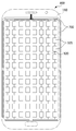
BRIEF DESCRIPTION OF THE DRAWINGS Fig. 1 is a plan view showing the arrangement position of an elastic supporter in a touch pressure sensor and a touch screen panel including the same according to the present invention. Fig.
FIG. 2 is a plan view showing an arrangement position of the first electrode member for pressure sensing in the touch-sensitive sensor according to the present invention and a touch screen panel including the touch-
FIG. 3 is a plan view showing an arrangement position of the second electrode member for pressure sensing in the touch-sensitive sensor according to the present invention and a touch screen panel including the touch-
FIG. 4 is an enlarged cross-sectional view of a touch sensor panel according to an embodiment of the present invention.
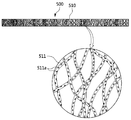
FIG. 5 is a schematic view illustrating an elastic supporting body in a touch pressure sensing sensor and a touch screen panel including the same according to the present invention. FIG.
The present invention will now be described in detail with reference to the accompanying drawings. Hereinafter, a repeated description, a known function that may obscure the gist of the present invention, and a detailed description of the configuration will be omitted. Embodiments of the present invention are provided to more fully describe the present invention to those skilled in the art. Accordingly, the shapes and sizes of the elements in the drawings and the like can be exaggerated for clarity.
FIG. 1 is a plan view showing an arrangement position of an
4 is an enlarged cross-sectional view illustrating an embodiment of a touch pressure sensor and a touch screen panel including the same according to the present invention.
1 to 4, a touch pressure sensor according to an exemplary embodiment of the present invention includes a transparent
The touch screen panel according to an embodiment of the present invention includes a
The
The
The
That is, the
5 is a schematic view illustrating one embodiment of the
The
The nanofiber member is formed by mixing a polymer material having chemical resistance with the
More specifically, the nanofiber member is manufactured by electrospinning using a polymer spinning solution containing a polymer resin, a
The polymer resin may be one of PVDF (polyvinylidene fluoride), PS (polystyrene), PMMA (poly (methylmethacrylate)) and PAN.
The
The
It is noted that the
The
When the thickness of the
The thickness of the
The thickness d 1 of the
The
In addition, the second electrode member for pressure sensing 700 may include a plurality of electrode patterns corresponding to the
In addition, the
1 to 4, the transparent
The
The cover
The first
The transparent
The
Although not shown, the
The
The first
When the first
The first
The first
The
The
The
2 is a plan view showing the first
The first electrode member for pressure sensing 600 may include a plurality of electrode patterns disposed at a portion corresponding to the bezel of the cover substrate so as to be spaced around the first
That is, the
3 is a plan view showing the second
A
The second electrode member for pressure sensing 700 may include a plurality of electrode patterns disposed at a portion corresponding to the bezel of the cover substrate so as to be spaced around the second
That is, the second electrode member for pressure sensing 700 may be disposed on the same plane as the second
The
4, the
An
The
The air vent holes 800 may be formed in the respective electrode patterns of the
The
The
The
Although not shown, the touch pressure sensor according to the present invention may further include a sealing member (not shown) for sealing the
The present invention is installed in the transparent
The present invention can be manufactured together with the touch sensor of the touch screen panel, thereby simplifying the manufacturing process and greatly reducing the manufacturing cost.
While the present invention has been particularly shown and described with reference to exemplary embodiments thereof, it is evident that many alternatives, modifications, and variations will be apparent to those skilled in the art in light of the above teachings. will be.
100: cover base 110: bezel portion
200: display panel unit 300: touch sensor unit
310: first substrate 311: first touch sensing electrode
320: second substrate 321: second touch sensing electrode
400: transparent adhesive layer 410: cover transparent adhesive member
420: substrate transparent bonding member 430: panel transparent bonding member
500: elastic support 510: elastic membrane member
511:
600: first electrode member for pressure sensing 700: second electrode member for pressure sensing
800: air vent hole
Claims (20)
An elastic support bonded to the transparent adhesive layer;
A first electrode member for pressure sensing disposed on an upper side of the elastic supporter;
And a second pressure-sensing electrode member disposed on a lower side of the elastic supporter.
Wherein the elastic supporter is an elastic membrane member formed of a fibrous body.
Wherein the elastic membrane member is a nanofiber member formed of nanofibers.
Wherein a conductive powder is distributed in the fibers of the fibrous body.
Wherein the elastic membrane member comprises an elastic gel member inserted into spaces between fibers of the fibrous body.
Wherein at least one of the pressure sensing first electrode member and the pressure sensing second electrode member has an air vent hole for discharging air in the elastic membrane member.
And a sealing member for sealing the air vent hole.
A cover base covering a screen of the display panel unit;
A touch sensor unit disposed between the display panel unit and the cover substrate and sensing that the user touches the cover substrate;
A transparent adhesive layer disposed between the cover substrate and the display panel unit;
An elastic support bonded to the transparent adhesive layer;
A first electrode member for pressure sensing disposed on an upper side of the elastic supporter; And
And a second pressure-sensing electrode member disposed on a lower side of the elastic supporter.
Wherein the elastic support, the first electrode member for pressure sensing, and the second electrode member for pressure sensing are disposed correspondingly to the lower side of the bezel portion in the cover base.
Wherein the transparent adhesive layer comprises: a cover transparent bonding member which is disposed between the touch sensor unit and the cover substrate and to which the touch sensor unit and the cover substrate are bonded; And
And a panel transparent bonding member disposed between the touch sensor unit and the display panel unit and bonded to the touch sensor unit and the display panel unit,
Wherein the elastic supporter is attached to one of the cover transparent bonding member and the panel transparent bonding member.
The touch sensor unit includes a first substrate having a first touch sensing electrode for sensing a touch and a second substrate having a second touch sensing electrode for sensing a touch, And a base transparent bonding member disposed between the second base and adhering the first base and the second base,
And the elastic support is adhered to the base transparent bonding member.
Wherein the touch sensor unit includes a first touch sensing electrode and a second touch sensing electrode for sensing a touch,
Wherein the first electrode member for pressure sensing is formed on the same plane as the first touch sensing electrode,
And the second electrode member for pressure sensing is formed on the same plane as the second touch sensing electrode.
Wherein the touch sensor unit includes a first touch sensing electrode and a second touch sensing electrode for sensing a touch,
Wherein the first touch sensing electrode and the second touch sensing electrode are disposed opposite to each other and wherein one of the first touch sensing electrode and the second touch sensing electrode is a ground electrode.
Wherein the touch sensor unit includes a first substrate having a first touch sensing electrode for sensing a touch and a second substrate having a second touch sensing electrode for sensing a touch,
Wherein the first electrode member for pressure sensing is formed on the first substrate together with the first touch sensing electrode and is disposed on a bezel portion of the cover substrate,
Wherein the second electrode member for pressure sensing is formed on the second substrate together with the second touch sensing electrode and is disposed on a bezel portion of the cover substrate.
Wherein the elastic support is an elastic membrane member formed of a fibrous body.
Wherein the elastic membrane member is a nanofiber member formed of nanofibers.
Wherein a conductive powder is distributed in the fibers of the fibrous body.
Wherein the elastic membrane member comprises an elastic gel member inserted into spaces between fibers of the fiber body.
Wherein at least one of the pressure sensing first electrode member and the pressure sensing second electrode member has an air vent hole for discharging air in the elastic membrane member.
Further comprising a sealing member for sealing the air vent hole.
Priority Applications (1)
| Application Number | Priority Date | Filing Date | Title |
|---|---|---|---|
| KR1020160017899A KR20170096476A (en) | 2016-02-16 | 2016-02-16 | Touch Pressure Sensor for Touch Screen Panel and Touch Screen Panel comprising the Touch Pressure Sensor |
Applications Claiming Priority (1)
| Application Number | Priority Date | Filing Date | Title |
|---|---|---|---|
| KR1020160017899A KR20170096476A (en) | 2016-02-16 | 2016-02-16 | Touch Pressure Sensor for Touch Screen Panel and Touch Screen Panel comprising the Touch Pressure Sensor |
Publications (1)
| Publication Number | Publication Date |
|---|---|
| KR20170096476A true KR20170096476A (en) | 2017-08-24 |
Family
ID=59758098
Family Applications (1)
| Application Number | Title | Priority Date | Filing Date |
|---|---|---|---|
| KR1020160017899A KR20170096476A (en) | 2016-02-16 | 2016-02-16 | Touch Pressure Sensor for Touch Screen Panel and Touch Screen Panel comprising the Touch Pressure Sensor |
Country Status (1)
| Country | Link |
|---|---|
| KR (1) | KR20170096476A (en) |
Cited By (2)
| Publication number | Priority date | Publication date | Assignee | Title |
|---|---|---|---|---|
| US11681389B2 (en) | 2019-03-05 | 2023-06-20 | Samsung Display Co., Ltd. | Touch sensor and display device |
| US11875001B2 (en) | 2019-01-30 | 2024-01-16 | Samsung Display Co., Ltd. | Touch sensor and display device |
-
2016
- 2016-02-16 KR KR1020160017899A patent/KR20170096476A/en unknown
Cited By (2)
| Publication number | Priority date | Publication date | Assignee | Title |
|---|---|---|---|---|
| US11875001B2 (en) | 2019-01-30 | 2024-01-16 | Samsung Display Co., Ltd. | Touch sensor and display device |
| US11681389B2 (en) | 2019-03-05 | 2023-06-20 | Samsung Display Co., Ltd. | Touch sensor and display device |
Similar Documents
| Publication | Publication Date | Title |
|---|---|---|
| US9395830B2 (en) | Wired electrode of touch screen panel | |
| CN108369464B (en) | Touch pressure sensing device | |
| JP5916516B2 (en) | Three-dimensional curved touch panel and electronic device casing using the same | |
| KR101380693B1 (en) | Electrostatic capacitive touch screen | |
| TWI465964B (en) | Touch keyboard and method for making the same | |
| CN105426008B (en) | Pressure sensitive touching display screen and portable electronic product | |
| CN103003782B (en) | Electronic equipment and there is the portable terminal of this electronic equipment | |
| TWI529582B (en) | Touch panel with a function of fingerprint identification | |
| CN106155403B (en) | Touch control element | |
| CN101329609B (en) | Touch control panel with touch control press key | |
| KR20130005297A (en) | Transparent piezoelectric sheet with frame containing transparent piezoelectric sheet, touch panel containing transparent piezoelectric sheet, and electronic device | |
| JP2018112854A (en) | Capacitance type sensor device | |
| CN111033451A (en) | Input device manufacturing method and input device | |
| KR20170096476A (en) | Touch Pressure Sensor for Touch Screen Panel and Touch Screen Panel comprising the Touch Pressure Sensor | |
| US10514804B2 (en) | Input device and input device manufacturing method | |
| CN102859472B (en) | Electronic equipment and possess the portable terminal of this electronic equipment | |
| KR102427788B1 (en) | Touch Pressure Sensor | |
| KR20120039884A (en) | Touch screen panel and fabricating method for the same | |
| CN205353979U (en) | Forced induction touch -control display screen and portable electronic products | |
| JP6875982B2 (en) | Pressure-sensitive electrostatic switch | |
| KR102469364B1 (en) | Touch Pressure Sensor | |
| JP2021012425A (en) | Pressure sensitive touch sensor and pressure sensitive touch sensor module | |
| KR102622607B1 (en) | Touch pressure detecting device | |
| JP2020193840A (en) | Pressure sensitive touch sensor and pressure sensitive touch sensor module | |
| KR20170096473A (en) | Touch Sensor for Touch Screen Panel, Manufacturing Method of Cover for Touch Screen Panel and Touch Screen Panel comprising the Cover Film |