KR20170095139A - Optical fiber cutting apparatus - Google Patents
Optical fiber cutting apparatus Download PDFInfo
- Publication number
- KR20170095139A KR20170095139A KR1020170018097A KR20170018097A KR20170095139A KR 20170095139 A KR20170095139 A KR 20170095139A KR 1020170018097 A KR1020170018097 A KR 1020170018097A KR 20170018097 A KR20170018097 A KR 20170018097A KR 20170095139 A KR20170095139 A KR 20170095139A
- Authority
- KR
- South Korea
- Prior art keywords
- optical fiber
- eccentric cam
- blade member
- blade
- glass fiber
- Prior art date
Links
Images


Classifications
-
- G—PHYSICS
- G02—OPTICS
- G02B—OPTICAL ELEMENTS, SYSTEMS OR APPARATUS
- G02B6/00—Light guides; Structural details of arrangements comprising light guides and other optical elements, e.g. couplings
- G02B6/24—Coupling light guides
- G02B6/25—Preparing the ends of light guides for coupling, e.g. cutting
Landscapes
- Physics & Mathematics (AREA)
- General Physics & Mathematics (AREA)
- Optics & Photonics (AREA)
- Light Guides In General And Applications Therefor (AREA)
Abstract
Description
본 발명은 광섬유의 유리 섬유 부분을 절단하는 블레이드 부재의 위치 조정이 가능한 광섬유 절단 장치에 관한 것이다.The present invention relates to an optical fiber cutting apparatus capable of adjusting the position of a blade member for cutting a glass fiber portion of an optical fiber.
최근에, 대용량 및 고속의 정보 전송에 대한 요구가 높아지고 있어서, 오피스 빌딩이나 일반 가정 내에서의 광섬유 통신망의 정비가 진행되고 있다. 예를 들어, 간선(main line)으로부터 가정 내로 광섬유를 끌어들이는 경우, 간선 측의 광섬유와 가정 내의 광섬유를 접속할 필요가 있다. 광섬유를 접속하는 경우, 유리 섬유 부분이 광섬유 단부의 피복을 제거함으로써 노출되고, 노출된 유리 섬유 부분은 절단되고, 절단된 파단면이 접해진 상태로 접속이 수행된다.In recent years, there is a growing demand for large-capacity and high-speed information transmission, and the maintenance of fiber-optic communication networks in office buildings and general households is progressing. For example, when an optical fiber is drawn into the home from the main line, it is necessary to connect the optical fiber on the side of the main line and the optical fiber in the home. When the optical fiber is connected, the glass fiber portion is exposed by removing the cover of the optical fiber end portion, the exposed glass fiber portion is cut, and the connection is performed with the cut end surface being in contact with each other.
블레이드 부재에 의해 광섬유를 절단하고, 용수철이나 블레이드 압력 조정 나사 등으로 구성되는 블레이드 압력 조정 기구를 포함하며, 광섬유를 절단할 때 블레이드 압력 조정 기구에 의해 블레이드 부재의 블레이드 압력이 조정되는 광섬유 절단 장치가 특허문헌 1 및 2에 개시되어 있다.An optical fiber cutting apparatus includes a blade pressure adjusting mechanism that cuts an optical fiber by a blade member and includes a spring or a blade pressure adjusting screw and adjusts the blade pressure of the blade member by a blade pressure adjusting mechanism when cutting the optical fiber Are disclosed in
게다가, 블레이드 압력 조정 지그(blade pressure adjustment jig)를 이용하여 조정 나사를 회전시킴으로써, 블레이드를 수직으로 이동시키는 것에 의해 블레이드 압력 조정을 실행하는 방법이 특허문헌 3에 개시되어 있다.In addition, Patent Document 3 discloses a method of performing blade pressure adjustment by vertically moving the blade by rotating the adjustment screw using a blade pressure adjustment jig.
특허문헌 1 및 2의 설명된 바와 같이, 블레이드 압력이 용수철에 의해 조정된다면, 블레이드의 이동량은 용수철의 탄성력에 의존하기 때문에, 블레이드 압력을 정밀하게 조정하는 것은 어렵다. 게다가, 특허문헌 2 및 3에 설명된 바와 같이, 블레이드 압력이 조정 나사에 의해 조정되는 경우에는, 나사의 이동량이 그대로 블레이드의 이동량이 되기 때문에, 숙련을 필요로 한다.As described in
본 발명의 예시적인 실시예는 블레이드 부재의 위치가 간편한 구성으로, 보다 정밀하게 조정 가능한 광섬유 절단 장치를 제공하는 것이다.An exemplary embodiment of the present invention is to provide an optical fiber cutting apparatus that can be adjusted more precisely with a simple configuration of the position of the blade member.
예시적인 실시예에 따른 광섬유 절단 장치는,In an optical fiber cutting apparatus according to an exemplary embodiment,
광섬유의 유리 섬유 부분을 고정하도록 구성된 고정 부재와,A fixing member configured to fix a glass fiber portion of the optical fiber;
유리 섬유 부분에 상처(flaw)를 형성하도록 구성된 블레이드 부재와,A blade member configured to form a flaw in the glass fiber portion,
고정 부재에 의해 고정되는 유리 섬유 부분에 대해 블레이드 부재의 상대 위치를 조정하도록 구성된 위치 조정부를 포함하고,And a position adjustment section configured to adjust a relative position of the blade member to the glass fiber portion fixed by the fixing member,
위치 조정부는 회동축(rotational shaft)과, 이 회동축의 회전 중심과 상이한 회전 중심을 갖는 원호(arc)를 포함하는 편심 캠 영역(eccentric cam region)을 포함하며,The position adjusting section includes an eccentric cam region including an arc having a rotational shaft and a rotational center different from the rotational center of the rotational shaft,
블레이드 부재의 상대 위치는 편심 캠 영역의 외주부의 위치에 따라 변화된다.The relative position of the blade member changes in accordance with the position of the outer peripheral portion of the eccentric cam region.
예시적인 실시예에 따르면, 블레이드 부재의 위치가 간편한 구성으로, 보다 정밀하게 조정 가능한 광섬유 절단 장치를 제공할 수 있다.According to the exemplary embodiment, it is possible to provide an optical fiber cutting apparatus that can be adjusted more precisely with a simple configuration of the position of the blade member.
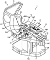
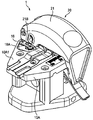
도 1은 본 실시예의 광섬유 절단 장치와, 이 광섬유 절단 장치에 장착되는 홀더의 정면 사시도,
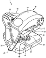
도 2는 광섬유 절단 장치의 배면 사시도,
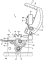
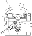
도 3은 광섬유 절단 장치의 우측면도,
도 4는 광섬유 절단 장치의 클램프 커버가 폐쇄된 상태의 정면 사시도,
도 5는 도 4에 도시된 상태의 우측면도,
도 6은 클램프 커버가 개방된 상태에서, 블레이드 부재의 보지 부재의 회전 레버가 상방으로 올려질 때의 저면 사시도,
도 7은 클램프 커버가 로크 부재에 의해 로킹된 상태의 배면 사시도,
도 8은 도 7에 도시된 상태의 우측면도,
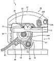
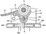
도 9는 블레이드 부재의 위치 조정 기구를 도시하는 부분 단면도,
도 10은 도 9의 중심의 종단면도,
도 11은 위치 조정 기구의 조정 레버가 조정된 상태를 도시하는 부분 단면도.1 is a front perspective view of an optical fiber cutting device of the present embodiment, a holder mounted on the optical fiber cutting device,
2 is a rear perspective view of the optical fiber cutting device,
3 is a right side view of the optical fiber cutting device,
4 is a front perspective view of the optical fiber cutting apparatus in a state in which the clamp cover is closed;
5 is a right side view of the state shown in Fig. 4,
6 is a bottom perspective view when the rotation lever of the holding member of the blade member is lifted upward with the clamp cover opened,
7 is a rear perspective view showing a state in which the clamp cover is locked by the lock member,
Fig. 8 is a right side view of the state shown in Fig. 7,
9 is a partial cross-sectional view showing a position adjusting mechanism of the blade member,
10 is a longitudinal sectional view of the center of Fig. 9,
11 is a partial cross-sectional view showing a state in which the adjustment lever of the position adjustment mechanism is adjusted.
(본 발명의 실시예의 설명)(Description of Embodiments of the Present Invention)
처음에 본 발명의 실시예의 내용이 나열되고 설명될 것이다.First, the contents of embodiments of the present invention will be listed and explained.
(1) 예시적인 실시예에 따른 광섬유 절단 장치는,(1) In the optical fiber cutting apparatus according to the exemplary embodiment,
광섬유의 유리 섬유 부분을 고정하도록 구성된 고정 부재와, A fixing member configured to fix a glass fiber portion of the optical fiber;
유리 섬유 부분에 상처를 형성하도록 구성된 블레이드 부재와,A blade member configured to form a wound on the glass fiber portion,
고정 부재에 의해 고정되는 유리 섬유 부분에 대해 블레이드 부재의 상대 위치를 조정하도록 구성된 위치 조정부를 포함하고,And a position adjustment section configured to adjust a relative position of the blade member to the glass fiber portion fixed by the fixing member,
위치 조정부는 회동축과, 이 회동축의 회전 중심과 상이한 회전 중심을 갖는 원호를 포함하는 편심 캠 영역을 포함하며,The position adjusting section includes a pivot shaft and an eccentric cam area including an arc having a rotation center different from the rotation center of the pivot shaft,
블레이드 부재의 상대 위치는 편심 캠 영역의 외주부의 위치에 따라 변화된다.The relative position of the blade member changes in accordance with the position of the outer peripheral portion of the eccentric cam region.
이 구성에 따르면, 간편한 구성으로, 블레이드 부재의 위치를 보다 정밀하게 조정하고, 블레이드 압력의 미조정을 용이하게 수행할 수 있다.According to this configuration, the position of the blade member can be adjusted more precisely with a simple configuration, and the fine adjustment of the blade pressure can be easily performed.
(2) 위치 조정부는,(2)
편심 캠 영역으로부터 돌출하는 돌출부와,A protrusion protruding from the eccentric cam area,
돌출부에 접하는 조정 나사를 포함하고,And an adjusting screw in contact with the projection,
조정 나사의 회전에 의한 이동에 따라, 돌출부를 편심 캠 영역의 회전 중심축 주위로 회전시킴으로써, 편심 캠 영역이 회전된다.The eccentric cam area is rotated by rotating the projecting portion around the rotation center axis of the eccentric cam area in accordance with the movement of the adjustment screw by rotation.
이 구성에 따르면, 조정 나사의 이동량은 편심 캠 영역의 회전량으로 변환하고, 편심 캠의 회전 중심으로부터 외주까지의 거리의 변화량은 블레이드 부재의 이동량으로 변환된다. 그러므로, 블레이드 부재의 이동량의 최소 변화량을 보다 작게 할 수 있다.According to this configuration, the amount of movement of the adjusting screw is converted into the amount of rotation of the eccentric cam area, and the amount of change in the distance from the center of rotation of the eccentric cam to the outer periphery is converted into the amount of movement of the blade member. Therefore, the minimum change amount of the amount of movement of the blade member can be made smaller.
(3) 위치 조정부는, 조정 나사의 이동에 의해서 부여되는 편심 캠 영역의 회전 방향과 반대 방향으로 회전되도록, 돌출부를 이동시키도록 구성된 가압부를 더 포함하는 것이 바람직하다.(3) It is preferable that the position adjusting section further includes a pressing section configured to move the projection so as to rotate in a direction opposite to the rotating direction of the eccentric cam region provided by the movement of the adjusting screw.
이 구성에 따르면, 조정 나사의 이동 방향과 반대 방향의 이동이 가압부에 의해 편심 캠 영역에 부여된다. 그러므로, 블레이드 압력의 조정을 보다 정밀하게 수행할 수 있다.According to this configuration, the movement in the direction opposite to the moving direction of the adjusting screw is given to the eccentric cam area by the pressing portion. Therefore, adjustment of the blade pressure can be performed more precisely.
(본 발명의 실시예의 상세)(Details of Embodiments of the Present Invention)
이하에, 본 발명의 바람직한 실시예는 첨부 도면을 참조하여 상세하게 설명된다. 게다가, 도면의 설명에 있어서, 동일한 도면 부호는 동일 또는 상당 요소에 주어지고, 중복된 설명은 생략된다.Hereinafter, preferred embodiments of the present invention will be described in detail with reference to the accompanying drawings. In addition, in the description of the drawings, the same reference numerals are given to the same or equivalent elements, and redundant explanations are omitted.
도 1 및 도 2는 각각, 본 발명의 실시예의 광섬유 절단 장치와, 이 광섬유 절단 장치에 장착되는 홀더의 정면 사시도 및 배면 사시도이다. 도 3은 광섬유 절단 장치의 우측면도이다.1 and 2 are a front perspective view and a rear perspective view, respectively, of an optical fiber cutting device and an holder mounted on the optical fiber cutting device of the embodiment of the present invention. 3 is a right side view of the optical fiber cutting device.
광섬유 절단 장치(1)는 본체부(10)와 클램프 커버(20)를 포함한다. 본체부(10)는 홀더 고정부(11)와, 하부 고정 부재(12)와, 섬유 위치 결정부(13)와, 블레이드 부재(14)와, 보지 부재(15)를 구비한다. 클램프 커버(20)는 아암 부재(21)와, 회동 부재(22)와, 상부 고정 부재(23)와, 장착 부재(24)와, 레버 가압부(25)와, 파단 부재(26)를 구비한다. 광섬유(도시되지 않음)의 유리 섬유 부분을 클램핑하기 위한 클램프부는 본체부(10)의 하부 고정 부재(12)와, 클램프 커버(20)의 상부 고정 부재(23)로 구성된다.The optical
본체부(10)는 상부 플레이트부(10A)와, 하부 플레이트부(10B)와, 상부 플레이트부(10A)와 하부 플레이트부(10B)를 연결하는 칼럼부(10C)로 구성된다. 상부 플레이트부(10A)의 상면(10A1) 상에 홀더 고정부(11)가 제공된다. 홀더 고정부(11)는 광섬유를 그 보호 피복의 부분에서 보지하는 홀더(30)를 고정하기 위해 리세스 형상으로 형성된 부분이다. 일례로서, 홀더(30)는 외경이 상이한 복수의 유형의 광섬유를 수용 가능한 섬유 수용 홈(31)이 홀더(30)의 상면에 제공된 구조를 갖는다.The
하부 고정 부재(12)는 상부 플레이트부(10A)의 상면(10A1)에 클램프 커버(20)를 대면시키는 위치에 고정된다. 하부 고정 부재(12)는 일정 간격을 두고 배치된 한 쌍의 하부 클램프부(12A, 12B)로 구성된다. 각각의 하부 클램프부(12A, 12B)는, 금속의 받침대의 상면에 고무재가 끼워맞춤되고, 이 고무재의 상면[이하, 클램프면(12P)이라 함]에 광섬유의 유리 섬유 부분이 장착되도록 구성된다. 한 쌍의 하부 클램프부(12A, 12B)는 후술되는 한 쌍의 상부 고정 부재(23)에 대면하고, 클램프 커버(20)를 폐쇄함으로써 광섬유의 유리 섬유 부분을 개재 및 고정할 수 있다.The
섬유 위치 결정부(13)는 홀더 고정부(11)와 반대측에 배치되는 하부 고정 부재(12)의 하부 클램프부(12B)의 외측에 제공된다. 섬유 위치 결정부(13)는 상부 플레이트부(10A)의 상면(10A1)으로부터 상방으로 돌출하는 부재이고, 섬유 위치 결정부(13)에는, 광섬유의 유리 섬유 부분이 섬유 위치 결정부(13)의 중앙부에 수용되는 가이드 홈(13A)이 제공된다. 보호 피복 부분은 홀더(30)의 섬유 수용 홈(31)에 수용되고, 노출된 유리 섬유 부분은 하부 클램프부(12A, 12B)에 장착되며, 유리 섬유 부분의 첨단(tip)은 섬유 위치 결정부(13)의 가이드 홈(13A)에 수용되고, 이에 의해 소망의 길이를 갖는 유리 섬유 부분이 첨단에서 노출된 광섬유는 상부 플레이트부(10A)의 적절한 위치에 배치된다.The
한 쌍의 하부 클램프부(12A, 12B) 사이에 노출 구멍(16)이 형성되고, 블레이드 부재(14)는 노출 구멍(16)으로부터 상방으로 돌출한다. 블레이드 부재(14)는, 원판(disk) 주위에 블레이드가 형성되고, 도 3에 도시되는 바와 같이, 그 중심에 지지축(14A)을 포함하도록 구성된다. 보지 부재(15)는 지지축(14A)을 거쳐서 블레이드 부재(14)를 보지하기 위한 부재이고, 보지 부재(15)에는 블레이드 보지부(41)와, 회동축(42)과, 회동 레버(43)와, 금속봉(44)과, 조정 레버(45)가 제공된다. 블레이드 부재(14)의 지지축(14A)은 보지 부재(15)의 블레이드 보지부(41)에 장착된다. 보지 부재(15)는 회동축(42)에 의해 본체부(10)의 칼럼부(10C)에 장착된다. 회동 레버(43)는 블레이드 보지부(41)로부터 측부로 돌출하도록 제공된다. 회동 레버(43)는 수직으로 이동되고, 이에 의해 보지 부재(15)는 회동축(42)을 중심으로 본체부(10)의 칼럼부(10C)에 대해서 회동할 수 있다. 그러므로, 블레이드 보지부(41)에 장착된 블레이드 부재(14)는 회동 레버(43)의 이동에 의해, 회동축(42)을 중심으로 원호 운동된다. 봉(44)은, 블레이드 보지부(41) 측의 회동 레버(43)의 영역에서, 홀더(30) 내에 보지되는 광섬유의 길이 방향을 따라, 회동 레버(43)로부터 연장되도록 제공된다. 조정 레버(45)는 회동축(42)으로부터 하방으로 돌출하도록 제공된다. 조정 레버(45)를 사용하여 수행되는 광섬유의 클램프부에 대한 블레이드 부재(14)의 위치 조정 방법은 이하에 상세하게 설명된다.An
클램프 커버(20)는, 하부 고정 부재(12)와, 섬유 위치 결정부(13)와, 블레이드 부재(14)가 본체부(10)의 상부 플레이트부(10A)에 배치된 영역을 커버하도록 제공되는 기다란 아암 부재(21)를 포함한다. 아암 부재(21)는 회동 부재(22)를 거쳐서 본체부(10)에 회동 가능하게 연결된다.The
상부 고정 부재(23)는 아암 부재(21)의 배면측의 하부 고정 부재(12)에 대면하는 위치에 배치된다. 상부 고정 부재(23)는 일정 간격을 두고 배치된 한 쌍의 상부 클램프부(23A, 23B)로 구성된다. 한 쌍의 상부 클램프부(23A, 23B)는 장착 부재(24)에 장착된다. 장착 부재(24)는 회동 부재(22)를 거쳐서 상부 플레이트부(10A) 및 아암 부재(21)에 회동 가능하게 연결된다. 게다가, 장착 부재(24)는 아암 부재(21)에 제공된 긴 구멍(21A)에 삽입되는 돌기부(24A)를 포함한다. 게다가, 아암 부재(21)의 배면과 상부 고정 부재(23) 사이에 압축 용수철(도시되지 않음)이 제공된다. 이러한 구성에 따르면, 상부 고정 부재(23)는 긴 구멍(21A)의 길이 방향으로 아암 부재(21)에 대해 슬라이딩 가능하다.The upper fixing
레버 가압부(25)는, 아암 부재(21)가 폐쇄된 상태에서 회동 부재(22)가 제공되는 부분에 대향하는 아암 부재(21)의 측부에, 아암 부재(21)로부터 실질적으로 직각으로 본체부(10)를 향해 돌출하도록 제공된다. 레버 가압부(25)는, 아암 부재(21)를 폐쇄하도록 회동시켰을 때, 보지 부재(15)의 회동 레버(43)를 하방으로 가압할 수 있도록, 상부 바닥부(upper bottom)가 폭넓은 사다리꼴(역삼각) 형상으로 형성된다. 이러한 구성에 따르면, 본체부(10)에 대해 클램프 커버(20)를 폐쇄할 때, 회동 레버(43)는 레버 가압부(25)에 의해 하방으로 가압되고, 블레이드 부재(14)가 원호 운동되고, 하부 및 상부 고정 부재(12, 23)에 의해 고정된 광섬유의 유리 섬유 부분에 상처를 입힐 수 있다.The
블레이드 부재(14)에 의해 유리 섬유 부분에 대한 상처를 진전시킴으로써 유리 섬유 부분을 파단시키기 위한 파단 부재(26)가 상부 클램프부(23A, 23B) 사이에 제공된다. 파단 부재(26)는 장착 부재(24)에 고정된 부재이고, 상부 클램프부(23A, 23B)의 상면으로부터 약간 돌출하도록 배치된다. 이러한 구성에 따르면, 회동 레버(43)의 하향 이동에 근거하여 원호 운동되는 블레이드 부재(14)에 의해서 상처가 형성된 유리 섬유 부분은 가압되고, 상처를 진전시킴으로써 파단시킬 수 있다. 파단 부재(26)는 예를 들면, 고무재가 금속의 받침대의 상면에 끼워맞춤되도록 구성된다. 유리 섬유 부분은 블레이드 부재(14)에 의해 상처입혀진 부분으로부터 확실히 파단되고, 파단 부재(26)에 의해 상처를 진전시켜서 파단함으로써, 양호한 파단면을 형성할 수 있다.A breaking
본체부(10) 및 클램프 커버(20)는 아암 부재(21)와 장착 부재(24) 사이의 용수철 부재(도시되지 않음)에 의해 서로 개방 방향으로 바이어싱(bias)된다. 본체부(10)의 상부 플레이트부(10A)와 클램프 커버(20)가 개방된 상태에서 형성되는 각도(개방 각도)(θ)는 일례로서, 약 90도로 설정된다. 그러므로, 절단 작업이 완료된 후, 클램프 커버(20)로부터 손을 놓으면, 클램프 커버(20)는 용수철 부재의 바이어싱력을 사용함으로써 자동으로 개방된다. 그러므로, 본체부(10)와 클램프 커버(20)가 용수철 부재의 바이어싱력으로 개방된 상태를 보지할 수 있기 때문에, 홀더 고정부(11)에 홀더(30)를 장착하는 것이 용이하다. 게다가, 유리 섬유 부분이 절단된 후, 홀더(30)로부터 광섬유를 용이하게 제거할 수 있다.The
다음에, 상술된 광섬유 절단 장치(1)에 의해 광섬유의 유리 섬유 부분을 절단할 때의 광섬유 절단 장치(1)의 동작의 일례가 도 1 내지 도 6을 참조하여 설명된다. 도 4는 광섬유 절단 장치(1)의 클램프 커버(20)가 폐쇄된 상태의 정면 사시도이고, 도 5는 도 4에 도시된 상태의 우측면도이다. 게다가, 도 6은 클램프 커버(20)가 개방된 상태에서 보지 부재(15)의 회동 레버(43)가 상방으로 올려졌을 때의 저면 사시도이다.Next, an example of the operation of the optical
먼저, 도 1 내지 도 3에 도시되는 바와 같이, 작업자는 본체부(10)와 클램프 커버(20)가 개방된 경우에, 소망의 길이의 유리 섬유 부분이 첨단에서 노출된 광섬유의 보호 피복 부분이, 홀더 고정부(11)에 장착된 홀더(30)의 섬유 수용 홈(31)에 수용되게 한다. 그러므로, 작업자는 광섬유의 유리 섬유 부분이 하부 클램프부(12A, 12B)에 장착되게 하여, 섬유 위치 결정부(13)의 가이드 홈(13A)에 수용되게 한다.First, as shown in Figs. 1 to 3, when the
이 상태에서, 작업자가 개방 상태에 있는 클램프 커버(20)[아암 부재(21)]를 본체부(10)를 향해 회동시키면, 도 4 및 도 5에 도시되는 바와 같이, 광섬유의 유리 섬유 부분은 서로 대면하는 하부 클램프부(12A, 12B)와 상부 클램프부(23A, 23B)에 의해서 개재 및 고정된다. 그러므로, 레버 가압부(25)는 회동 레버(43)를 가압하고, 이에 의해 회동 레버(43)는 하방으로 이동된다. 하부 및 상부 고정 부재(12, 23) 사이에 고정된 광섬유의 유리 섬유 부분은, 회동 레버(43)의 하향 이동에 근거하여 원호 운동되는 블레이드 부재(14)에 의해 상처입혀진다. 그러므로, 유리 섬유 부분은 파단 부재(26)에 의해, 상처가 형성된 유리 섬유 부분을 가압하는 것에 의해 상처를 진전시킴으로써 파단된다.In this state, when the clamp cover 20 (the arm member 21) in the open state is turned toward the
유리 섬유 부분의 절단 작업이 완료되고, 작업자의 손이 아암 부재(21)로부터 떨어지면, 도 6에 도시되는 바와 같이, 클램프 커버(20)[아암 부재(21) 및 장착 부재(24)]는 아암 부재(21)와 장착 부재(24) 사이에 제공된 용수철 부재의 바이어싱력에 의해서 개방된다. 그 후, 작업자가 보지 부재(15)의 회동 레버(43) 또는 봉(44)을 상방으로 이동시키고, 이에 의해 블레이드 부재(14)를 보지한 보지 부재(15)는 회동 레버(43)가 상부 플레이트부(10A)에 접하는 대기 위치로 이동된다.6, the clamp cover 20 (the
게다가, 봉(44) 대신에, 회동 레버(43) 또는 보지 부재(15)의 일부가 본체부(10)의 칼럼부(10C)의 표면(10C1)에 대향하는 측부에 돌출하고, 이러한 표면(10C1)에는 블레이드 부재(14) 및 보지 부재(15)가 제공된다. 그 부분은 보지 부재(15)를 이동시키는 경우에 조작부로서 사용할 수도 있다.Further, instead of the
상술된 광섬유 절단 장치(1)는 광섬유가 장착되는 본체부(10)와, 이 본체부(10)에 회동 가능하게 연결되고 본체부(10)를 향해 회동됨으로써 본체부와의 사이에 광섬유를 고정하는 클램프 커버(20)와, 광섬유의 고정된 유리 섬유 부분에 상처를 입히는 블레이드 부재(14)와, 본체부(10)에 장착되고 블레이드 부재(14)를 보지하는 보지 부재(15)를 포함한다. 클램프 커버(20)는 보지 부재(15)를 가압하고, 이에 의해 블레이드 부재(14)는 원호 운동되어, 유리 섬유 부분에 상처를 입힌다. 구체적으로는, 클램프 커버(20)는 본체부(10)에 대면하는 상태에서 본체부(10) 측으로 돌출되는 레버 가압부(25)를 구비한다. 보지 부재(15)는, 클램프 커버(20)가 본체부(10)를 향해 회동될 때 레버 가압부(25)에 의해 가압되는 회동 레버(43)를 구비한다. 이 구성에 따르면, 본체부(10)를 향해 클램프 커버(20)를 회동시킬 뿐인 간단한 구성으로, 광섬유를 본체부(10)와 클램프 커버(20) 사이에 고정하여, 블레이드 부재(14)가 원호 운동되게 하는 단계와, 광섬유의 유리 섬유 부분에 상처를 입히는 단계와, 유리 섬유 부분을 절단하는 단계로 구성되는 일련의 단계를 한 번에 수행할 수 있다. 그러므로, 작업자가 한 손으로 광섬유를 가압하면서, 다른 한 손으로 광섬유 절단 장치(1)의 클램프 커버(20)를 회동시키고, 이에 의해 작업자가 광섬유 절단 작업을 수행할 수 있는 구성을 가질 수 있다. 그러므로, 절단 작업이 간편화되고, 절단 작업의 단축화를 도모할 수 있다.The above-described optical
게다가, 도 6에 도시되는 바와 같이, 본체부(10)의 칼럼부(10C)의 면(10C1)의 상부측에 자석(17)이 제공되고, 이 면(10C1)에는 블레이드 부재(14)와 보지 부재(15)가 제공된다. 광섬유 절단 작업 후에, 작업자가 회동 레버(43) 또는 봉(44)을 상방으로 이동시키면, 봉(44)의 일단부가 자석(17)에 부착되어 보지된다. 그러므로, 보지 부재(15)를 회동 레버(43)가 상부 플레이트부(10A)에 접하는 대기 위치에 고정할 수 있다. 그러므로, 블레이드 부재(14)의 예기치 않은 원호 운동으로 인해, 광섬유의 유리 섬유 부분에 상처를 형성하는 것을 방지할 수 있다.6, a
게다가, 봉(44) 대신에, 회동 레버(43) 또는 보지 부재(15)의 일부가 면(10C1) 측으로 돌출되거나, 회동 레버(43) 또는 보지 부재(15)가 면(10C1)에 근접하고, 그 일부가 자석(17)에 부착되어 보지될 수도 있다.Further, instead of the
게다가, 도 7에 도시되는 바와 같이, 상부 플레이트부(10A)의 상면(10A1) 상의 클램프 커버(20)의 회동 부재(22) 근방에 로크 기구(18)가 제공된다. 게다가, 아암 부재(21) 내의 로크 기구(18)에 대면하는 위치에 노치부(21B)(도 1 및 도 2 참조)가 제공된다. 로크 기구(18)는 나사(18A)를 중심으로 회동 가능하고, 로크 기구(18)의 첨단은 노치부(21B)에 삽입 가능하다. 상술된 바와 같이, 도 8에 도시되는 바와 같이, 아암 부재(21)는 로크 기구(18)의 첨단을 아암 부재(21)의 노치부(21B)에 삽입시킴으로써, 전 개방 상태가 되지 않도록 반 개방 상태에서 고정될 수 있다. 상술된 바와 같이, 하부 및 상부 고정 부재(12, 23), 또는 노출 구멍(16)으로부터 돌출하는 블레이드 부재(14)는, 광섬유 절단 장치(1)가 로크 기구(18)를 이용하여 반 개방 상태에 있게 됨으로써 노출될 수 없다. 그러므로, 광섬유 절단 장치(1)를 전용의 수용 케이스 등에 수용하지 않고도 안전하게 운반할 수 있다. 게다가, 하부 고정 부재(12)의 고무재가 상부 고정 부재(23)의 고무재와 강한 힘으로 접촉하는 것을 방지할 수 있다. 그러므로, 클램프 커버(20)가 반 개방 상태로 장기간 폐쇄된다 하더라도, 상부 및 하부 고무재의 변형 가능성을 저감시킬 수 있다.7, a
게다가, 상술된 실시예에 있어서, 블레이드 부재(14)에 의해 상처가 형성된 광섬유의 유리 섬유 부분을 파단 부재(26)에 의해 가압함으로써 유리 섬유 부분이 파단되지만, 반드시 파단 부재(26)에 의해 파단되도록 구성되는 것은 아닐 수도 있다. 즉, 유리 섬유 부분을 절단하는 블레이드 부재(14)의 높이가 조정되고, 이에 의해, 블레이드 부재(14)는 유리 섬유 부분에 깊게 들어가고, 블레이드 부재(14)는 또한 원호 운동되는 도중에, 유리 섬유 부분을 절단할 수 있다.Further, in the above-described embodiment, the glass fiber portion of the optical fiber wound by the
다음에, 조정 레버(45)에 의해 수행되는, 광섬유가 장착된 클램프면(12P)에 대한 블레이드 부재(14)의 위치를 조정하기 위한 방법이 도 9 내지 도 11을 참조하여 설명된다.Next, a method for adjusting the position of the
도 9는 블레이드 부재의 위치 조정 기구를 도시하는 부분 단면도이고, 도 10은 도 9에 도시된 위치 조정 기구의 중심의 종단면도이다.Fig. 9 is a partial cross-sectional view showing the position adjusting mechanism of the blade member, and Fig. 10 is a longitudinal sectional view of the center of the position adjusting mechanism shown in Fig.
도 9에 도시된 바와 같이, 블레이드 부재(14)를 보지하는 보지 부재(15)의 회동축(42)은 편심 캠 기구를 포함한다. 즉, 회동축(42)은 이 회동축(42)의 회전 중심축과 상이한 회전 중심축을 갖는 편심 캠 영역(42A)을 구비한다. 즉, 회동축(42)의 회전 중심축으로부터 편심 캠 영역(42A)의 외주[캠면(42B)]의 거리는 변화된다. 도 10에 도시되는 바와 같이, 캠면(42B)의 주위에 베어링(46)이 장착되고, 이 베어링(46)의 주위에 블레이드 보지부(41)가 고정된다. 즉, 블레이드 보지부(41)는 베어링(46)을 거쳐서 회동축(42)에 회전 가능하게 연결된다.As shown in Fig. 9, the rotating
게다가, 도 9 및 도 10에 도시되는 바와 같이, 조정 레버(45)는, 베어링(46)이 장착된 부분보다 본체부(10)의 칼럼부(10C) 측을 향해 보다 근접한 편심 캠 영역(42A)의 부분으로부터 하방으로 돌출하도록 고정된다. 즉, 조정 레버(45)는 편심 캠 영역(42A)의 회전 중심축과 동일한 회전 중심축을 갖고, 편심 캠 영역(42A)과 일체적으로 회전 가능하다. 도 9에 있어서, 일례로서, 조정 레버(45)는 수직 방향으로 연장되도록 위치된다. 조정 레버(45)의 첨단은 본체부(10)의 하부 플레이트부(10B)에 제공된 개구부(10B1)를 관통한다. 개구부(10B1)는 블레이드 부재(14)의 반경 방향을 따라 긴 구멍 형상으로 절단된다. 하부 플레이트부(10B)에, 블레이드 부재(14)의 반경 방향을 따라 개방된 소경 개구부(10B2, 10B3)가 추가로 제공된다. 소경 개구부(10B2, 10B3)는 개구부(10B1)의 양단에서 각각 개구부(10B1)와 연통한다. 이러한 소경 개구부(10B2, 10B3) 각각 내로 조정 나사(F)가 삽입된다. 조정 나사(F)는 조정 레버(45)의 첨단이 조정 나사(F)의 첨단 사이에 개재되도록 위치될 수 있다.9 and 10, the
도 11은 조정 레버(45)가 조정된 상태를 도시하는 부분 단면도이다.11 is a partial cross-sectional view showing a state in which the
개구부(10B1) 내에 삽입된 조정 레버(45)는 소경 개구부(10B2, 10B3)를 따라 조정 나사(F) 중 적어도 하나를 이동시킴으로써, 블레이드 부재(14)의 반경 방향을 따라 개구부(10B1) 내에서 이동 가능하다. 본 예에 있어서, 조정 레버(45)는, 예를 들면, 도 9 및 도 11에서의 좌측에 제공된 소경 개구부(10B2) 내에 삽입된 조정 나사(F)를 느슨하게 하고, 우측에 제공된 소경 개구부(10B3) 내로 삽입된 조정 나사(F)를 조이는 것에 의해, 도 9에 도시된 위치로부터 도 11에 도시된 위치까지 이동된다. 상술된 바와 같이, 조정 레버(45)는 회동축(42)의 회전 방향으로 이동되고, 이에 의해 조정 레버(45)가 고정된 편심 캠 영역(42A)은 또한 회동축(42)을 중심으로 회전한다. 편심 캠 영역(42A)은 회동축(42)의 회전 중심과 상이한 중심을 갖는 편심 캠으로 구성된다. 그러므로, 편심 캠 영역(42A)이 회전되고, 이에 의해 회동축(42)의 회전 중심으로부터 수직 방향의 캠면(42B)까지의 거리가 변화된다. 그 결과, 베어링(46)을 거쳐서 캠면(42B)의 주위에 연결된 블레이드 보지부(41)의 위치가 승강한다. 이 구성에 따르면, 블레이드 보지부(41)에 보지되는 블레이드 부재(14)의 위치는 조정 나사(F)에 의해 조정 레버(45)를 회동축(42)의 회전 방향으로 이동시킴으로써 승강될 수 있다. 예를 들어, 도 11에 도시되는 바와 같이, 조정 레버(45)가 조정 나사(F)의 회전 이동에 의해 수직 방향에서 시계 방향으로 30도만큼 이동된 경우에, 블레이드 부재(14)의 위치는 0.25㎜만큼 상승된다.The
상술된 바와 같이, 본 실시예에 따른 광섬유 절단 장치(1)는, 고정 부재(12, 23)에 의해 고정된 광섬유의 유리 섬유 부분에 대한 블레이드 부재(14)의 상대 위치를 조정하는 위치 조정부로서, 회동축(42)과, 이 회동축(42)의 회전 중심과 상이한 회전 중심을 갖는 원호를 포함하는 편심 캠 영역(42A)을 포함한다. 블레이드 부재(14)의 상대 위치는 편심 캠 영역(42A)의 외주부의 위치에 따라 변화된다. 이 구성에 따르면, 간편한 구성으로, 블레이드 부재(14)의 위치를 보다 정밀하게 조정하고, 블레이드 압력의 미조정을 용이하게 수행할 수 있다. 게다가, 조정 나사(F)의 회전 이동에 의해 조정 레버(45)를 회전시킴으로써, 클램프면(12P)에 대한 블레이드 부재(14)의 위치를 조정하는 것에 의해, 블레이드 부재(14)의 이동량의 최소 변화량을 종래의 이동량보다 더욱 작게 할 수 있다. 하부 및 상부 고정 부재(12, 23) 사이에 고정된 광섬유와 블레이드 부재(14)의 접촉량의 미조정을 용이하게 수행할 수 있다.As described above, the optical
게다가, 상술된 실시예에 있어서, 조정 나사(F)는 소경 개구부(10B2, 10B3) 각각 내로 삽입되지만, 본 발명은 이러한 예에 한정되지 않는다. 예를 들어, 소경 개구부(10B2, 10B3) 중 임의의 하나에, 조정 레버(45)를 가압하기 위한 가압부로서, 압축 용수철이 제공될 수도 있다. 가압부로서의 압축 용수철은, 다른 하나의 소경 개구부 내에 삽입된 조정 나사(F)의 이동에 의해 부여된 편심 캠 영역의 회전 방향과 반대 방향으로 조정 레버(45)를 회전시키도록 조정 레버(45)를 이동시킨다. 조정 나사의 이동 방향과 반대 방향의 이동이 압축 용수철에 의해 편심 캠 영역(42A)에 부여되기 때문에, 블레이드 압력의 조정을 정밀하게 수행할 수 있다.Further, in the above-described embodiment, the adjusting screw F is inserted into each of the small-diameter openings 10B2 and 10B3, but the present invention is not limited to this example. For example, a compression spring may be provided to any one of the small-diameter openings 10B2 and 10B3 as a pressing portion for pressing the
게다가, 상술된 실시예에 있어서, 블레이드 부재(14)의 위치는 편심 캠 영역(42A)으로부터 하방으로 돌출하는 조정 레버(45)를 이동시키는 것에 의해 편심 캠 영역(42A)을 회전시킴으로써 조정되지만, 본 발명은 이러한 예에 한정되지 않는다. 예를 들어, 블레이드 부재(14)의 위치는 조정 레버(45)를 제공하지 않고 편심 캠 영역(42A)을 직접 회전시킴으로써 조정될 수도 있다.In addition, in the above-described embodiment, the position of the
게다가, 상술된 실시예에 있어서, 편심 캠 영역(42A) 또는 조정 레버(45)는 원호 운동으로 광섬유의 유리 섬유 부분에 상처를 형성하는 블레이드 부재(14)의 위치를 조정하는 기구로서 제공되지만, 본 발명은 이러한 예에 한정되지 않는다. 예를 들어, 광섬유 절단 장치는 선형 슬라이드 이동이 가능한 슬라이드 기구를 포함하는 보지 부재를 구비하고, 광섬유 절단 장치에는, 보지 부재에 보지되고 선형 슬라이드 이동에 의해 광섬유에 상처를 형성하는 블레이드 부재의 위치를 조정하는 수단으로서, 상술된 실시예의 편심 캠 기구, 조정 레버, 조정 나사와 같은 위치 조정 기구가 제공될 수도 있다. 그러므로, 선형 이동에 의해 광섬유에 상처를 형성하는 블레이드 부재에 있어서도, 보다 정밀한 위치 조정을 수행할 수 있다.Moreover, in the above-described embodiment, the
이상에서, 본 발명은 특정 실시예를 참조하여 상세하게 설명되었다. 그러나, 당업자는 다양한 변경 및 수정이 본 발명의 정신과 범위를 일탈하는 일 없이 이루어질 수도 있다는 것을 인식할 것이다. 게다가, 상술된 구성 부재의 개수, 위치, 형상 등은 상기 실시예에 한정되지 않지만, 본 발명을 실시하는데 적합한 개수, 위치, 형상 등으로 변경될 수도 있다.In the foregoing, the present invention has been described in detail with reference to specific embodiments. However, those skilled in the art will recognize that various changes and modifications may be made without departing from the spirit and scope of the invention. Furthermore, the number, position, shape, and the like of the above-described constituent members are not limited to the above embodiment, but may be changed to the number, position, shape, and the like suitable for practicing the present invention.
1 : 광섬유 절단 장치
12 : 하부 고정 부재
14 : 블레이드 부재
23 : 상부 고정 부재
42 : 회동축
42A : 편심 캠 영역
45 : 조정 레버(돌출부의 일례)1: Optical fiber cutting device 12: Lower fixing member
14: blade member 23: upper fixing member
42:
45: Control lever (example of projection)
Claims (3)
광섬유의 유리 섬유 부분을 고정하도록 구성된 고정 부재와,
상기 유리 섬유 부분에 상처를 형성하도록 구성된 블레이드 부재와,
상기 고정 부재에 의해 고정된 유리 섬유 부분에 대한 상기 블레이드 부재의 상대 위치를 조정하도록 구성된 위치 조정부를 포함하고,
상기 위치 조정부는 회동축과, 상기 회동축의 회전 중심과 상이한 회전 중심을 갖는 원호를 포함하는 편심 캠 영역을 포함하며,
상기 블레이드 부재의 상대 위치는 상기 편심 캠 영역의 외주부의 위치에 따라 변화되는
광섬유 절단 장치.In an optical fiber cutting apparatus,
A fixing member configured to fix a glass fiber portion of the optical fiber;
A blade member configured to form a wound on the glass fiber portion;
And a position adjusting unit configured to adjust a relative position of the blade member to the glass fiber portion fixed by the fixing member,
Wherein the position adjustment unit includes a rotation shaft and an eccentric cam area including an arc having a rotation center different from the rotation center of the rotation shaft,
The relative position of the blade member is changed according to the position of the outer peripheral portion of the eccentric cam region
Optical fiber cutting device.
상기 위치 조정부는,
상기 편심 캠 영역으로부터 돌출하는 돌출부와,
상기 돌출부에 접하는 조정 나사를 포함하고,
상기 조정 나사의 회전에 의한 이동에 따라 상기 돌출부를 상기 편심 캠 영역의 회전 중심축 주위로 회전시킴으로써 상기 편심 캠 영역을 회전시키는
광섬유 절단 장치.The method according to claim 1,
The position adjustment unit,
A protrusion protruding from the eccentric cam area;
And an adjusting screw in contact with the projection,
And rotating the eccentric cam area by rotating the projecting part around the rotation center axis of the eccentric cam area in accordance with the rotation of the adjustment screw
Optical fiber cutting device.
상기 위치 조정부는, 상기 조정 나사의 이동에 의해 부여되는 상기 편심 캠 영역의 회전 방향과 반대 방향으로 회전되도록, 상기 돌출부를 이동시키도록 구성된 가압부를 더 포함하는
광섬유 절단 장치.3. The method of claim 2,
The position adjusting section may further include a pressing section configured to move the projection so as to be rotated in a direction opposite to the rotating direction of the eccentric cam region provided by the movement of the adjusting screw
Optical fiber cutting device.
Priority Applications (1)
| Application Number | Priority Date | Filing Date | Title |
|---|---|---|---|
| KR1020190076396A KR102372461B1 (en) | 2016-02-12 | 2019-06-26 | Optical fiber cutting apparatus |
Applications Claiming Priority (2)
| Application Number | Priority Date | Filing Date | Title |
|---|---|---|---|
| JP2016025133A JP6623490B2 (en) | 2016-02-12 | 2016-02-12 | Optical fiber cutting equipment |
| JPJP-P-2016-025133 | 2016-02-12 |
Related Child Applications (1)
| Application Number | Title | Priority Date | Filing Date |
|---|---|---|---|
| KR1020190076396A Division KR102372461B1 (en) | 2016-02-12 | 2019-06-26 | Optical fiber cutting apparatus |
Publications (1)
| Publication Number | Publication Date |
|---|---|
| KR20170095139A true KR20170095139A (en) | 2017-08-22 |
Family
ID=59562082
Family Applications (2)
| Application Number | Title | Priority Date | Filing Date |
|---|---|---|---|
| KR1020170018097A KR20170095139A (en) | 2016-02-12 | 2017-02-09 | Optical fiber cutting apparatus |
| KR1020190076396A KR102372461B1 (en) | 2016-02-12 | 2019-06-26 | Optical fiber cutting apparatus |
Family Applications After (1)
| Application Number | Title | Priority Date | Filing Date |
|---|---|---|---|
| KR1020190076396A KR102372461B1 (en) | 2016-02-12 | 2019-06-26 | Optical fiber cutting apparatus |
Country Status (4)
| Country | Link |
|---|---|
| US (1) | US20170235050A1 (en) |
| JP (1) | JP6623490B2 (en) |
| KR (2) | KR20170095139A (en) |
| CN (1) | CN107085265A (en) |
Families Citing this family (6)
| Publication number | Priority date | Publication date | Assignee | Title |
|---|---|---|---|---|
| JP1563774S (en) * | 2016-05-27 | 2016-11-21 | ||
| US11065778B2 (en) * | 2017-03-24 | 2021-07-20 | Fujikura Ltd. | Optical fiber cutter |
| US10739517B2 (en) * | 2018-09-21 | 2020-08-11 | Ofs Fitel, Llc | Cleaving optical fibers |
| EP3859414A4 (en) * | 2018-09-27 | 2022-07-06 | Sumitomo Electric Optifrontier Co., Ltd. | Optical fiber cutting device and optical fiber cutting method |
| US20220334320A1 (en) * | 2021-04-20 | 2022-10-20 | Palo Alto Research Center Incorporated | Optical fiber installation tool |
| US11668889B2 (en) | 2021-04-20 | 2023-06-06 | Palo Alto Research Center Incorporated | System for applying pre-strain to an optical sensor |
Family Cites Families (17)
| Publication number | Priority date | Publication date | Assignee | Title |
|---|---|---|---|---|
| US2393919A (en) * | 1943-05-11 | 1946-01-29 | Dictaphone Corp | Cable stripping device |
| JPS61121813A (en) * | 1984-11-17 | 1986-06-09 | Dia Kogyo Kk | Pipe cutoff machine |
| CN86206315U (en) * | 1986-08-30 | 1987-07-29 | 北方工业大学 | Planetary tube-cutting machine |
| US4890385A (en) * | 1988-02-29 | 1990-01-02 | Tri Tool Inc. | Automatic feed system for a tube cutter |
| JPH0523819U (en) * | 1991-09-17 | 1993-03-30 | 株式会社共立 | Vibration cutting work machine |
| JP4045716B2 (en) | 2000-04-28 | 2008-02-13 | 住友電気工業株式会社 | Blade pressure adjusting method and blade pressure adjusting jig for optical fiber cutter |
| KR100471083B1 (en) * | 2002-12-24 | 2005-03-10 | 삼성전자주식회사 | Apparatus for cleavering optical fiber |
| BRPI0612362A2 (en) * | 2005-04-22 | 2010-11-03 | Ilsin Tech Co Ltd | portable fiber optic processing apparatus |
| JP5065800B2 (en) * | 2007-01-23 | 2012-11-07 | 住友電気工業株式会社 | Optical fiber cutting device |
| JP2010122555A (en) | 2008-11-21 | 2010-06-03 | Fujikura Ltd | Optical fiber-cutting apparatus |
| DE202010005766U1 (en) * | 2009-06-16 | 2010-10-28 | Weidmüller Interface GmbH & Co. KG | Tool for processing optical waveguides |
| CN201562921U (en) * | 2009-11-27 | 2010-08-25 | 南京智屯达科技有限公司 | Longitudinal and transverse cable cutter |
| CN201583682U (en) * | 2010-01-21 | 2010-09-15 | 上海大学 | Optical fiber cutting device |
| JP2012013717A (en) | 2010-06-03 | 2012-01-19 | Furukawa Electric Co Ltd:The | Optical fiber cutting device and method |
| JP5200064B2 (en) * | 2010-06-28 | 2013-05-15 | 住友電気工業株式会社 | Optical fiber cutter |
| JP5639455B2 (en) * | 2010-12-13 | 2014-12-10 | 株式会社フジクラ | Optical fiber cutting device and optical fiber cutting method |
| JP6593794B2 (en) * | 2016-02-12 | 2019-10-23 | Seiオプティフロンティア株式会社 | Optical fiber holder and optical fiber cutting device to which the optical fiber holder can be attached |
-
2016
- 2016-02-12 JP JP2016025133A patent/JP6623490B2/en active Active
-
2017
- 2017-02-06 US US15/425,033 patent/US20170235050A1/en not_active Abandoned
- 2017-02-09 KR KR1020170018097A patent/KR20170095139A/en active Search and Examination
- 2017-02-10 CN CN201710073449.4A patent/CN107085265A/en active Pending
-
2019
- 2019-06-26 KR KR1020190076396A patent/KR102372461B1/en active IP Right Grant
Also Published As
| Publication number | Publication date |
|---|---|
| US20170235050A1 (en) | 2017-08-17 |
| JP6623490B2 (en) | 2019-12-25 |
| JP2017142456A (en) | 2017-08-17 |
| KR20190079597A (en) | 2019-07-05 |
| CN107085265A (en) | 2017-08-22 |
| KR102372461B1 (en) | 2022-03-08 |
Similar Documents
| Publication | Publication Date | Title |
|---|---|---|
| KR20190079597A (en) | Optical fiber cutting apparatus | |
| KR101928642B1 (en) | Optical fiber cutting apparatus | |
| US6754426B2 (en) | Hand-held optical fiber cutting apparatus | |
| US20050011327A1 (en) | Cutter with laser generator that irradiates cutting position on workpiece to facilitate alignment of blade with cutting position | |
| JP2006251034A (en) | Optical fiber cutting device | |
| JP2012008472A (en) | Optical fiber cutter | |
| JP2010036269A (en) | Portable cutting machine | |
| JP4254429B2 (en) | Tabletop slide cutting machine | |
| US7198547B2 (en) | Lens edger | |
| US4274572A (en) | Apparatus for severing an optical fiber | |
| JP2018146802A (en) | Optical fiber cutting device | |
| JP2014071284A (en) | Optical fiber cutter | |
| JP2002047023A (en) | Glass cutter holder and glass scribing device | |
| JP2009083333A (en) | Bench cutting machine | |
| CN112771427A (en) | Optical fiber cutting device and optical fiber cutting method | |
| JP2012008432A (en) | Cross cut device for eyeglass lens, and cross cut method of eyeglass lens | |
| JP2000225603A (en) | Cutting positioning apparatus for cutting machine | |
| DE102005001950A1 (en) | Glass fiber cutting device, has cutting wheel rotatable and adjustable about longitudinal axis of glass fiber for cutting fiber at right angle to its longitudinal axis and partially along its outer periphery | |
| CN210982803U (en) | Cutting device | |
| WO2021106428A1 (en) | Coating removal tool | |
| JP4139501B2 (en) | Cutter device for spotlight | |
| JP2006069213A (en) | Cutting machine | |
| JP4300584B2 (en) | Cutting machine | |
| JPH11153713A (en) | Cutter for wire-shaped light transmission body | |
| JPH09105819A (en) | Optical fiber cutting jig |
Legal Events
| Date | Code | Title | Description |
|---|---|---|---|
| A201 | Request for examination | ||
| E902 | Notification of reason for refusal | ||
| E601 | Decision to refuse application | ||
| AMND | Amendment | ||
| E902 | Notification of reason for refusal | ||
| AMND | Amendment |