KR20170093031A - Cage and tapered roller bearing using the same - Google Patents
Cage and tapered roller bearing using the same Download PDFInfo
- Publication number
- KR20170093031A KR20170093031A KR1020160014473A KR20160014473A KR20170093031A KR 20170093031 A KR20170093031 A KR 20170093031A KR 1020160014473 A KR1020160014473 A KR 1020160014473A KR 20160014473 A KR20160014473 A KR 20160014473A KR 20170093031 A KR20170093031 A KR 20170093031A
- Authority
- KR
- South Korea
- Prior art keywords
- diameter portion
- cage
- inner ring
- small diameter
- tapered roller
- Prior art date
Links
Images


Classifications
-
- F—MECHANICAL ENGINEERING; LIGHTING; HEATING; WEAPONS; BLASTING
- F16—ENGINEERING ELEMENTS AND UNITS; GENERAL MEASURES FOR PRODUCING AND MAINTAINING EFFECTIVE FUNCTIONING OF MACHINES OR INSTALLATIONS; THERMAL INSULATION IN GENERAL
- F16C—SHAFTS; FLEXIBLE SHAFTS; ELEMENTS OR CRANKSHAFT MECHANISMS; ROTARY BODIES OTHER THAN GEARING ELEMENTS; BEARINGS
- F16C19/00—Bearings with rolling contact, for exclusively rotary movement
- F16C19/22—Bearings with rolling contact, for exclusively rotary movement with bearing rollers essentially of the same size in one or more circular rows, e.g. needle bearings
- F16C19/34—Bearings with rolling contact, for exclusively rotary movement with bearing rollers essentially of the same size in one or more circular rows, e.g. needle bearings for both radial and axial load
- F16C19/36—Bearings with rolling contact, for exclusively rotary movement with bearing rollers essentially of the same size in one or more circular rows, e.g. needle bearings for both radial and axial load with a single row of rollers
- F16C19/364—Bearings with rolling contact, for exclusively rotary movement with bearing rollers essentially of the same size in one or more circular rows, e.g. needle bearings for both radial and axial load with a single row of rollers with tapered rollers, i.e. rollers having essentially the shape of a truncated cone
-
- B—PERFORMING OPERATIONS; TRANSPORTING
- B29—WORKING OF PLASTICS; WORKING OF SUBSTANCES IN A PLASTIC STATE IN GENERAL
- B29C—SHAPING OR JOINING OF PLASTICS; SHAPING OF MATERIAL IN A PLASTIC STATE, NOT OTHERWISE PROVIDED FOR; AFTER-TREATMENT OF THE SHAPED PRODUCTS, e.g. REPAIRING
- B29C39/00—Shaping by casting, i.e. introducing the moulding material into a mould or between confining surfaces without significant moulding pressure; Apparatus therefor
- B29C39/02—Shaping by casting, i.e. introducing the moulding material into a mould or between confining surfaces without significant moulding pressure; Apparatus therefor for making articles of definite length, i.e. discrete articles
-
- B—PERFORMING OPERATIONS; TRANSPORTING
- B29—WORKING OF PLASTICS; WORKING OF SUBSTANCES IN A PLASTIC STATE IN GENERAL
- B29D—PRODUCING PARTICULAR ARTICLES FROM PLASTICS OR FROM SUBSTANCES IN A PLASTIC STATE
- B29D99/00—Subject matter not provided for in other groups of this subclass
- B29D99/006—Producing casings, e.g. accumulator cases
-
- F—MECHANICAL ENGINEERING; LIGHTING; HEATING; WEAPONS; BLASTING
- F16—ENGINEERING ELEMENTS AND UNITS; GENERAL MEASURES FOR PRODUCING AND MAINTAINING EFFECTIVE FUNCTIONING OF MACHINES OR INSTALLATIONS; THERMAL INSULATION IN GENERAL
- F16C—SHAFTS; FLEXIBLE SHAFTS; ELEMENTS OR CRANKSHAFT MECHANISMS; ROTARY BODIES OTHER THAN GEARING ELEMENTS; BEARINGS
- F16C33/00—Parts of bearings; Special methods for making bearings or parts thereof
- F16C33/30—Parts of ball or roller bearings
- F16C33/34—Rollers; Needles
- F16C33/36—Rollers; Needles with bearing-surfaces other than cylindrical, e.g. tapered; with grooves in the bearing surfaces
- F16C33/366—Tapered rollers, i.e. rollers generally shaped as truncated cones
-
- F—MECHANICAL ENGINEERING; LIGHTING; HEATING; WEAPONS; BLASTING
- F16—ENGINEERING ELEMENTS AND UNITS; GENERAL MEASURES FOR PRODUCING AND MAINTAINING EFFECTIVE FUNCTIONING OF MACHINES OR INSTALLATIONS; THERMAL INSULATION IN GENERAL
- F16C—SHAFTS; FLEXIBLE SHAFTS; ELEMENTS OR CRANKSHAFT MECHANISMS; ROTARY BODIES OTHER THAN GEARING ELEMENTS; BEARINGS
- F16C2220/00—Shaping
- F16C2220/02—Shaping by casting
Abstract
A cage is disclosed. An annular large-diameter portion having a larger diameter than the small-diameter portion and spaced apart from the small-diameter portion by a predetermined distance in the axial direction; And a plurality of partition walls spaced apart from each other in a circumferential direction so as to connect the small diameter portion and the large diameter portion and accommodating the tapered roller together with the small diameter portion and the large diameter portion, The fixing grooves are formed in the radially inner side and can be prevented from being damaged in the tapered roller bearing provided with the cage.
Description
The present invention relates to a cage, and more particularly, to a plastic cage and a tapered roller bearing using the same.
In general, a bearing is a mechanical element mounted between a rotating element and a non-rotating element to facilitate rotation of the rotating element while supporting the axis of the rotating element.
These bearings are divided into sliding bearings and rolling bearings depending on the state of contact with the shaft, and can be classified into a radial bearing and a thrust bearing according to the direction in which the load is applied.
The rolling bearing is capable of supporting a rotating shaft by a rolling body such as a ball or a roller. Rolling bearings having such a structure are advantageous in that the frictional resistance is smaller than that of a sliding bearing that directly contacts a part of the shaft. As a result, rolling bearings are currently used in various forms such as ball bearings, tapered roller bearings, and needle bearings depending on the shape of rolling elements.
The tapered roller bearing has a generally tapered cylindrical shape and is used for the purpose of simultaneously supporting the loads in the rotational axis direction and the radial direction. For example, a shaft of a power transmission device such as an axle in a vehicle may be supported, or an automatic transmission may be used.
5, the conventional tapered roller bearing includes an
The
The
The
6 is an assembled view showing a state in which the
SUMMARY OF THE INVENTION The present invention has been made in view of the above circumstances, and it is an object of the present invention to provide a cage which is free from the risk of occurrence of scratches or scratches on the surface of the taper roller during the assembling process, Roller bearings.
According to an embodiment of the present invention, there is provided a cage comprising an annular small-diameter portion, an annular large-diameter portion having a larger diameter than the small-diameter portion and spaced apart from the small- And a plurality of partition walls spaced apart from each other in a circumferential direction to connect the small diameter portion and the large diameter portion, the plurality of partition walls receiving the tapered roller together with the small diameter portion and the large diameter portion, Shaped fixing grooves are formed on the outer circumferential surface.
The partition wall having a first partition wall extending from the small-diameter portion to the large-diameter portion; And a second partition wall extending from the large diameter portion toward the small diameter portion, wherein the first partition wall extends inside the radius of the second partition to stably support the taper roller.
And a lubricant oil retaining groove extending in the longitudinal direction of the partition wall is formed on a radially outer side surface of the first partition wall.
The plurality of partition walls are spaced apart from each other by a predetermined distance in the circumferential direction, and the tapered roller pockets are formed by the two partition walls adjacent to each other, the large diameter portion, and the small diameter portion.
A tapered roller bearing according to an embodiment of the present invention comprises a cage according to any one of
Wherein the inner ring and the outer ring form an inner ring raceway surface and an outer ring raceway surface, respectively, which are opposite to each other; A planar surface extending in the axial direction is formed at one end of the inner ring raceway surface on the radially outer circumferential surface of the inner ring and a large diameter step protruding radially outward is formed on the other end of the inner ring raceway surface .
A fixing protrusion is protruded radially inward from one end of the outer ring raceway surface, and the fixing protrusion is inserted into a fixing groove formed in the cage to restrict movement of the cage.
The cage may be formed of a plastic material by a die process.
According to the cage and the tapered roller bearing using the cage according to the embodiment of the present invention, the small-diameter step of the inner ring is removed and the fixing groove is formed at one side of the cage so as to be fixed to the outer ring, So that scratches and scratches are prevented from being generated. Further, the tapered roller can be stably assembled to the cage, and the performance of the tapered roller bearing can be improved.
1 is a perspective view of a tapered roller bearing according to an embodiment of the present invention.
2 is a cross-sectional view of the AA portion of Fig.
3 is a perspective view of a cage in accordance with an embodiment of the present invention.
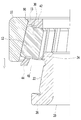
4 is an assembled cross-sectional view of a tapered roller bearing according to an embodiment of the present invention.
5 is a cross-sectional view of a tapered roller bearing according to the prior art.
6 is an assembled cross-sectional view of a tapered roller bearing according to the prior art.
Hereinafter, preferred embodiments of the present invention will be described in detail with reference to the accompanying drawings.
Throughout the specification, when a section includes a constituent element, it is understood that it can include other constituents, not excluding the other constituent elements unless specifically stated otherwise.
For convenience of explanation, the left side of the drawing in the axial direction is referred to as' one side ',' one end ',' one end 'and the like name, and the right side of the drawing in the axial direction is referred to as' other side, End " and similar names.
The parts denoted by the same reference numerals throughout the specification mean the same or similar components.
Hereinafter, embodiments of the present invention will be described in detail with reference to the accompanying drawings.
FIG. 1 is a perspective view of a tapered roller bearing according to an embodiment of the present invention, FIG. 2 is a cross-sectional view of AA portion of FIG. 1, FIG. 3 is a perspective view of a cage according to an embodiment of the present invention, Sectional view of a tapered roller bearing according to an embodiment.
The tapered roller bearing 1 according to the embodiment of the present invention includes an
On the inner circumferential surface of the
On the other hand, an inner
A large-
A plurality of
2 to 3, the
The
The
Further, a lubricant oil retaining groove S is formed on a radially outer side surface of the
Referring to FIG. 2, the outer circumferential surface of the small-
A part of the inner circumferential surface of the
The
4 is an assembled cross-sectional view of a tapered
Referring to FIG. 4, in order to assemble the tapered
The assembly of the
According to the embodiment of the present invention, since the small-diameter step is not formed in the
While the present invention has been particularly shown and described with reference to exemplary embodiments thereof, it is to be understood that the invention is not limited to the disclosed exemplary embodiments. Various modifications and variations are possible within the scope of the appended claims.
10: Outer ring
11: Fixing projection surface
12: outer ring raceway surface
13: Fixing projection
20: Inner ring
22: Inner ring raceway surface
24: Flat surface
26: Large diameter step
30: Taper roller
40: Cage
42: Small neck
44: Large neck
46:
47: first partition
48: second partition
50: Tapered roller pocket
90: Fixing groove
95: first support portion
97: second support portion
Claims (8)
An annular large diameter portion spaced apart from the small diameter portion by a predetermined distance in the axial direction and having a larger diameter than the small diameter portion; And
A plurality of partition walls spaced apart in a circumferential direction so as to connect the small diameter portion and the large diameter portion and accommodating the tapered roller together with the small diameter portion and the large diameter portion;
≪ / RTI >
And a fixing groove shaped like a pin is formed radially inwardly on the outer circumferential surface of the small diameter portion.
The partition wall
A first partition wall extending from the small diameter portion in the large diameter portion direction; And
A second partition wall extending from the large diameter portion in the direction of the small diameter portion;
/ RTI >
And the first partition wall extends inside the radius of the second partition to stably support the taper roller.
And a lubricant oil retaining groove extending in the longitudinal direction of the partition wall is formed on a radially outer side surface of the first partition wall.
Wherein the plurality of partition walls are spaced apart from each other by a predetermined distance in the circumferential direction, and a tapered roller pocket is formed by two partition walls adjacent to each other, the large diameter portion and the small diameter portion.
A plurality of tapered rollers inserted into the cage and rotatably supported;
An outer ring disposed radially outward about the cage; And
An inner ring disposed radially inward about the cage;
And a tapered roller bearing.
Wherein the inner ring and the outer ring form an inner ring raceway surface and an outer ring raceway surface, respectively, which are opposite to each other;
Characterized in that a flat surface extending in the axial direction is formed at one end of the inner ring raceway surface on the outer circumferential surface of the inner ring in the radial direction and a large diameter step protruded outward in the radial direction is formed on the other end of the inner ring raceway surface. bearing.
Wherein a fixing protrusion is protruded radially inward from one end of the outer ring raceway surface, and the fixing protrusion is inserted into a fixing groove formed in the cage to restrict movement of the cage.
Wherein the cage is formed of a plastic material by a die process.
Priority Applications (1)
| Application Number | Priority Date | Filing Date | Title |
|---|---|---|---|
| KR1020160014473A KR20170093031A (en) | 2016-02-04 | 2016-02-04 | Cage and tapered roller bearing using the same |
Applications Claiming Priority (1)
| Application Number | Priority Date | Filing Date | Title |
|---|---|---|---|
| KR1020160014473A KR20170093031A (en) | 2016-02-04 | 2016-02-04 | Cage and tapered roller bearing using the same |
Publications (1)
| Publication Number | Publication Date |
|---|---|
| KR20170093031A true KR20170093031A (en) | 2017-08-14 |
Family
ID=60142116
Family Applications (1)
| Application Number | Title | Priority Date | Filing Date |
|---|---|---|---|
| KR1020160014473A KR20170093031A (en) | 2016-02-04 | 2016-02-04 | Cage and tapered roller bearing using the same |
Country Status (1)
| Country | Link |
|---|---|
| KR (1) | KR20170093031A (en) |
Cited By (3)
| Publication number | Priority date | Publication date | Assignee | Title |
|---|---|---|---|---|
| KR20190048357A (en) * | 2017-10-31 | 2019-05-09 | 셰플러코리아(유) | A Tapered Roller Bearing Having Improved Assembling |
| KR20200034393A (en) * | 2018-09-21 | 2020-03-31 | 주식회사 만도 | Electric Power Steering Apparatus for Vehicle |
| KR102553662B1 (en) | 2022-06-30 | 2023-07-12 | 조범종 | Bearing housing with bearing outer ring and auxiliary footrest system for vehicle including the same |
-
2016
- 2016-02-04 KR KR1020160014473A patent/KR20170093031A/en not_active Application Discontinuation
Cited By (3)
| Publication number | Priority date | Publication date | Assignee | Title |
|---|---|---|---|---|
| KR20190048357A (en) * | 2017-10-31 | 2019-05-09 | 셰플러코리아(유) | A Tapered Roller Bearing Having Improved Assembling |
| KR20200034393A (en) * | 2018-09-21 | 2020-03-31 | 주식회사 만도 | Electric Power Steering Apparatus for Vehicle |
| KR102553662B1 (en) | 2022-06-30 | 2023-07-12 | 조범종 | Bearing housing with bearing outer ring and auxiliary footrest system for vehicle including the same |
Similar Documents
| Publication | Publication Date | Title |
|---|---|---|
| US8672555B2 (en) | Rolling bearing having internal lubrication | |
| WO2014163177A1 (en) | Tapered roller bearing-use resin made cage and tapered roller bearing provided with such cage | |
| EP1881216B1 (en) | Cage for roller bearing | |
| US20040141672A1 (en) | Resin-made ball retainer for a rolling bearing | |
| KR101454909B1 (en) | Taper roller bearing | |
| US11460075B2 (en) | Method and device for fitting an angular contact roller bearing | |
| JP6507764B2 (en) | Tapered roller bearings | |
| JPH05157116A (en) | Automatic aligning roller bearing with retainer | |
| KR20180034650A (en) | Each contact roller bearing, its assembly method and its apparatus | |
| KR20170093031A (en) | Cage and tapered roller bearing using the same | |
| JPH0742984B2 (en) | Roller bearing with lubricant reservoir | |
| KR20180037028A (en) | Method and apparatus for manufacturing each contact roller bearing | |
| CN104653625B (en) | Divide retainer and roller bearing | |
| KR101826198B1 (en) | Cage for ball bearing | |
| JP2015124796A (en) | Tapered roller bearing | |
| US8529134B2 (en) | Rolling bearing apparatus | |
| JP2008232420A (en) | Cage for radial ball bearing, and radial ball bearing | |
| JP2000320558A (en) | Synthetic resin made retainer for roller bearing | |
| JP2009275799A (en) | Deep groove ball bearing | |
| KR101838705B1 (en) | Cage and tapered roller bearing using the same | |
| JP7263944B2 (en) | Inner ring unit and tapered roller bearing | |
| US20140140650A1 (en) | Tandem rolling bearings with open cage | |
| KR101681272B1 (en) | Cage, and tapered roller bearing having the same | |
| CN114658759A (en) | Bearing without retainer | |
| KR101826196B1 (en) | Tandem ball bearing |
Legal Events
| Date | Code | Title | Description |
|---|---|---|---|
| A201 | Request for examination | ||
| E902 | Notification of reason for refusal | ||
| E601 | Decision to refuse application |