KR20170091216A - Non-wearable gaze tracking system at distance by background lighting and reference point lighting - Google Patents
Non-wearable gaze tracking system at distance by background lighting and reference point lighting Download PDFInfo
- Publication number
- KR20170091216A KR20170091216A KR1020160011610A KR20160011610A KR20170091216A KR 20170091216 A KR20170091216 A KR 20170091216A KR 1020160011610 A KR1020160011610 A KR 1020160011610A KR 20160011610 A KR20160011610 A KR 20160011610A KR 20170091216 A KR20170091216 A KR 20170091216A
- Authority
- KR
- South Korea
- Prior art keywords
- infrared
- user
- face
- camera
- lighting
- Prior art date
Links
Images


Classifications
-
- G06K9/00604—
-
- G06K9/2027—
-
- H04N13/0468—
-
- H04N13/0484—
Landscapes
- Eye Examination Apparatus (AREA)
Abstract
Description
The present invention relates to an infrared illumination configuration in a system for tracking a user's gaze using an infrared image.
Eye tracking technology to find the direction or position that the user is looking at can be divided into wearable and non-wearable types. In the case of non-wearable technology, it can be divided into near and far vision tracking systems depending on the distance between the user and the eyesight tracking system have. Most non-worn line-of-sight tracking technologies use one or more infrared lights and infrared cameras that know their location in advance. In the infrared image of the user's eye, the pupil is displayed in black with low brightness, and the iris surrounding the pupil has higher brightness, so pupil can be detected through boundary detection and circular fitting. In the cornea covering the pupil of the user, reflected light of infrared light is generated. The position of the reflected light is determined by the position of the infrared camera, the illumination, and the user's eye. Therefore, the gaze position of the user can be estimated by using the position of the center of the moving pupil according to the user's gaze position and the position of the reflected light that does not change according to the gaze.
In an environment where no external infrared light sources such as sunlight or incandescent lamps are present, a near-line tracking system can produce sufficient brightness for infrared imaging even with small-sized infrared illumination. However, the far-sight line tracking system must concentrate the illumination angle very narrowly or concentrate or use strong infrared light so that a sufficient amount of infrared light reaches a long distance. However, if the illumination angle of the illumination is narrowed, the range of the eye tracking can be narrowed because the infrared ray can not be irradiated when the user of the far distance moves to the upper, lower, left, and right sides. And the size of the whole eye tracking system and manufacturing cost are increased due to the enlargement of the power source unit and the heat dissipating unit.
In the present invention, in order to obtain an infrared image of sufficient brightness in a far-sight line tracking system using infrared light, a stronger infrared light should be used as a reference point light as the distance between the user and the far-sight line tracking system becomes longer, We are trying to solve the problem that the consumption is getting worse and the system becomes bigger.
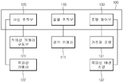
According to an embodiment of the present invention, a far-sight line tracking system is provided. The long-distance line-of-sight tracking system includes a line-of-sight tracer main body, a wide-angle camera for generating an image for tracing a user's face, an infrared ray detector for detecting an infrared ray directed to the user's face, An infrared ray camera for generating an infrared ray image including the cornea reflection light by infrared ray photographing of the face of the user, and an infrared ray camera for generating an infrared ray image including the cornea reflection light, And an infrared camera driving unit for adjusting the direction of the infrared camera so as to face the user's face.
One embodiment of the present invention is composed of hardware suitable for each role by dividing the infrared illumination used for long-distance line-of-sight into the background illumination for securing the light amount of the whole image and the reference point illumination for generating the reflected light in the cornea and searching for the reference position .
According to the configuration of the present invention, the background illumination can be installed at a position which is not fixed relatively close to the user, unlike the reference point illumination in which the position is fixed. Therefore, compared with the case where the background illumination is installed at a fixed position with the camera, The manufacturing cost, size, power, and heat required for the display device can be reduced.
Hereinafter, the present invention will be described with reference to the embodiments shown in the accompanying drawings. For the sake of clarity, throughout the accompanying drawings, like elements have been assigned the same reference numerals. It is to be understood that the present invention is not limited to the embodiments illustrated in the accompanying drawings, but may be embodied in many other specific forms without departing from the spirit or essential characteristics thereof.
FIG. 1 is a block diagram illustrating an exemplary configuration of a long-distance line-of-sight tracking system according to an exemplary embodiment of the present invention. Referring to FIG.
2 is a view for explaining an application example of a long-distance line-of-sight tracking system according to an embodiment of the present invention.
3 is a diagram for explaining a line-of-sight tracking method.
While the present invention has been described in connection with certain exemplary embodiments, it is to be understood that the invention is not limited to the disclosed embodiments, but, on the contrary, is intended to cover various modifications and similarities. It should be understood, however, that the invention is not intended to be limited to the particular embodiments, but includes all modifications, equivalents, and alternatives falling within the spirit and scope of the invention.
Hereinafter, the present invention will be described in detail with reference to the preferred embodiments of the present invention with reference to the accompanying drawings.
FIG. 1 is a block diagram exemplarily showing the configuration of a far-sight line tracking system according to an embodiment of the present invention. FIG. 2 is a view for explaining an application example of a far-sight line tracking system according to an embodiment of the present invention. And FIG. 3 is a view for explaining a line-of-sight tracking method.
1 to 3, the far-sight line tracking system includes a line-of-sight tracer
The wide-
(Hereinafter, referred to as an infrared ray image 300) is required for accurate eye tracking, the
If the user's face position information is provided after the initial operation or the user moves to provide new face position information after the initial operation, the
In another embodiment, the infrared
The
The
The one or more
It will be understood by those skilled in the art that the foregoing description of the present invention is for illustrative purposes only and that those of ordinary skill in the art can readily understand that various changes and modifications may be made without departing from the spirit or essential characteristics of the present invention. will be. It is therefore to be understood that the above-described embodiments are illustrative in all aspects and not restrictive.
It is intended that the present invention covers the modifications and variations of this invention provided they come within the scope of the appended claims and their equivalents. .
Claims (1)
A wide angle camera for generating an image for tracking a user's face;
An infrared backlight spaced apart from the gaze tracker main body and positioned adjacent to the user, the infrared background illuminating the user's face with infrared light;
A reference point illumination for irradiating an infrared ray of a relatively small intensity relative to the infrared background illumination toward the face of the user;
An infrared camera for infrared imaging the face of the user to generate an infrared image including cornea reflection light; And
And an infrared camera driving unit for adjusting the direction of the infrared camera so as to face the traced user's face.
Priority Applications (1)
| Application Number | Priority Date | Filing Date | Title |
|---|---|---|---|
| KR1020160011610A KR20170091216A (en) | 2016-01-29 | 2016-01-29 | Non-wearable gaze tracking system at distance by background lighting and reference point lighting |
Applications Claiming Priority (1)
| Application Number | Priority Date | Filing Date | Title |
|---|---|---|---|
| KR1020160011610A KR20170091216A (en) | 2016-01-29 | 2016-01-29 | Non-wearable gaze tracking system at distance by background lighting and reference point lighting |
Publications (1)
| Publication Number | Publication Date |
|---|---|
| KR20170091216A true KR20170091216A (en) | 2017-08-09 |
Family
ID=59652827
Family Applications (1)
| Application Number | Title | Priority Date | Filing Date |
|---|---|---|---|
| KR1020160011610A KR20170091216A (en) | 2016-01-29 | 2016-01-29 | Non-wearable gaze tracking system at distance by background lighting and reference point lighting |
Country Status (1)
| Country | Link |
|---|---|
| KR (1) | KR20170091216A (en) |
Cited By (1)
| Publication number | Priority date | Publication date | Assignee | Title |
|---|---|---|---|---|
| US10825196B2 (en) | 2019-02-15 | 2020-11-03 | Universal City Studios Llc | Object orientation detection system |
-
2016
- 2016-01-29 KR KR1020160011610A patent/KR20170091216A/en unknown
Cited By (2)
| Publication number | Priority date | Publication date | Assignee | Title |
|---|---|---|---|---|
| US10825196B2 (en) | 2019-02-15 | 2020-11-03 | Universal City Studios Llc | Object orientation detection system |
| US11741628B2 (en) | 2019-02-15 | 2023-08-29 | Universal City Studios Llc | Object orientation detection system |
Similar Documents
| Publication | Publication Date | Title |
|---|---|---|
| US9916005B2 (en) | Gaze tracking with projector | |
| CN107533362B (en) | Eye tracking device and method for operating an eye tracking device | |
| IL282522B2 (en) | Electronic spectacles | |
| US10481403B2 (en) | Contact lens with retinal camera | |
| US10922568B2 (en) | Driver monitoring apparatus and method for controlling illuminator thereof | |
| FI125445B (en) | Blick Control Device | |
| US10725292B2 (en) | Gaze-tracking system and aperture device | |
| KR20010031932A (en) | Eye tracking apparatus | |
| US20140226002A1 (en) | Measuring device that can be operated without contact and control method for such a measuring device | |
| Ebisawa et al. | Head-free, remote eye-gaze detection system based on pupil-corneal reflection method with easy calibration using two stereo-calibrated video cameras | |
| CN107997737B (en) | Eye imaging system, method and device | |
| US10452911B2 (en) | Gaze-tracking system using curved photo-sensitive chip | |
| WO2018164104A1 (en) | Eye image processing device | |
| CN110850594A (en) | Head-mounted visual equipment and eyeball tracking system for same | |
| KR20170091216A (en) | Non-wearable gaze tracking system at distance by background lighting and reference point lighting | |
| JP2011042179A (en) | Projector control device | |
| KR102469273B1 (en) | Gaze tracking apparatus and gaze tracking method | |
| US11796802B2 (en) | Device tracking gaze and method therefor | |
| JP6687195B2 (en) | Eye image processing device | |
| CN115665941A (en) | Sight following surgical illuminating lamp and sight following method | |
| CN218851023U (en) | Sight follows operation light | |
| KR20170090247A (en) | Apparatus for tracking gaze at a distance using auto tracking light | |
| KR101433788B1 (en) | Portable Iris Image Capture Device For Single-Eye | |
| JPH01185241A (en) | Direction detecting system for line of sight | |
| JP2018181025A (en) | Sight line detecting device |