KR20170084558A - Electronic Device and Operating Method Thereof - Google Patents
Electronic Device and Operating Method Thereof Download PDFInfo
- Publication number
- KR20170084558A KR20170084558A KR1020160003738A KR20160003738A KR20170084558A KR 20170084558 A KR20170084558 A KR 20170084558A KR 1020160003738 A KR1020160003738 A KR 1020160003738A KR 20160003738 A KR20160003738 A KR 20160003738A KR 20170084558 A KR20170084558 A KR 20170084558A
- Authority
- KR
- South Korea
- Prior art keywords
- electronic device
- processor
- sensor
- motion
- user
- Prior art date
Links
Images


Classifications
-
- G—PHYSICS
- G06—COMPUTING; CALCULATING OR COUNTING
- G06F—ELECTRIC DIGITAL DATA PROCESSING
- G06F3/00—Input arrangements for transferring data to be processed into a form capable of being handled by the computer; Output arrangements for transferring data from processing unit to output unit, e.g. interface arrangements
- G06F3/01—Input arrangements or combined input and output arrangements for interaction between user and computer
- G06F3/03—Arrangements for converting the position or the displacement of a member into a coded form
- G06F3/033—Pointing devices displaced or positioned by the user, e.g. mice, trackballs, pens or joysticks; Accessories therefor
- G06F3/0346—Pointing devices displaced or positioned by the user, e.g. mice, trackballs, pens or joysticks; Accessories therefor with detection of the device orientation or free movement in a 3D space, e.g. 3D mice, 6-DOF [six degrees of freedom] pointers using gyroscopes, accelerometers or tilt-sensors
-
- G—PHYSICS
- G06—COMPUTING; CALCULATING OR COUNTING
- G06F—ELECTRIC DIGITAL DATA PROCESSING
- G06F1/00—Details not covered by groups G06F3/00 - G06F13/00 and G06F21/00
- G06F1/16—Constructional details or arrangements
- G06F1/1613—Constructional details or arrangements for portable computers
- G06F1/1626—Constructional details or arrangements for portable computers with a single-body enclosure integrating a flat display, e.g. Personal Digital Assistants [PDAs]
-
- G—PHYSICS
- G06—COMPUTING; CALCULATING OR COUNTING
- G06F—ELECTRIC DIGITAL DATA PROCESSING
- G06F1/00—Details not covered by groups G06F3/00 - G06F13/00 and G06F21/00
- G06F1/16—Constructional details or arrangements
- G06F1/1613—Constructional details or arrangements for portable computers
- G06F1/163—Wearable computers, e.g. on a belt
-
- G—PHYSICS
- G06—COMPUTING; CALCULATING OR COUNTING
- G06F—ELECTRIC DIGITAL DATA PROCESSING
- G06F3/00—Input arrangements for transferring data to be processed into a form capable of being handled by the computer; Output arrangements for transferring data from processing unit to output unit, e.g. interface arrangements
- G06F3/01—Input arrangements or combined input and output arrangements for interaction between user and computer
- G06F3/011—Arrangements for interaction with the human body, e.g. for user immersion in virtual reality
- G06F3/015—Input arrangements based on nervous system activity detection, e.g. brain waves [EEG] detection, electromyograms [EMG] detection, electrodermal response detection
-
- G—PHYSICS
- G06—COMPUTING; CALCULATING OR COUNTING
- G06F—ELECTRIC DIGITAL DATA PROCESSING
- G06F3/00—Input arrangements for transferring data to be processed into a form capable of being handled by the computer; Output arrangements for transferring data from processing unit to output unit, e.g. interface arrangements
- G06F3/01—Input arrangements or combined input and output arrangements for interaction between user and computer
- G06F3/017—Gesture based interaction, e.g. based on a set of recognized hand gestures
-
- G—PHYSICS
- G06—COMPUTING; CALCULATING OR COUNTING
- G06F—ELECTRIC DIGITAL DATA PROCESSING
- G06F3/00—Input arrangements for transferring data to be processed into a form capable of being handled by the computer; Output arrangements for transferring data from processing unit to output unit, e.g. interface arrangements
- G06F3/01—Input arrangements or combined input and output arrangements for interaction between user and computer
- G06F3/03—Arrangements for converting the position or the displacement of a member into a coded form
- G06F3/0304—Detection arrangements using opto-electronic means
-
- G—PHYSICS
- G06—COMPUTING; CALCULATING OR COUNTING
- G06F—ELECTRIC DIGITAL DATA PROCESSING
- G06F3/00—Input arrangements for transferring data to be processed into a form capable of being handled by the computer; Output arrangements for transferring data from processing unit to output unit, e.g. interface arrangements
- G06F3/01—Input arrangements or combined input and output arrangements for interaction between user and computer
- G06F3/03—Arrangements for converting the position or the displacement of a member into a coded form
- G06F3/033—Pointing devices displaced or positioned by the user, e.g. mice, trackballs, pens or joysticks; Accessories therefor
- G06F3/038—Control and interface arrangements therefor, e.g. drivers or device-embedded control circuitry
-
- G—PHYSICS
- G06—COMPUTING; CALCULATING OR COUNTING
- G06F—ELECTRIC DIGITAL DATA PROCESSING
- G06F3/00—Input arrangements for transferring data to be processed into a form capable of being handled by the computer; Output arrangements for transferring data from processing unit to output unit, e.g. interface arrangements
- G06F3/01—Input arrangements or combined input and output arrangements for interaction between user and computer
- G06F3/048—Interaction techniques based on graphical user interfaces [GUI]
- G06F3/0481—Interaction techniques based on graphical user interfaces [GUI] based on specific properties of the displayed interaction object or a metaphor-based environment, e.g. interaction with desktop elements like windows or icons, or assisted by a cursor's changing behaviour or appearance
- G06F3/0482—Interaction with lists of selectable items, e.g. menus
-
- G—PHYSICS
- G06—COMPUTING; CALCULATING OR COUNTING
- G06F—ELECTRIC DIGITAL DATA PROCESSING
- G06F3/00—Input arrangements for transferring data to be processed into a form capable of being handled by the computer; Output arrangements for transferring data from processing unit to output unit, e.g. interface arrangements
- G06F3/01—Input arrangements or combined input and output arrangements for interaction between user and computer
- G06F3/048—Interaction techniques based on graphical user interfaces [GUI]
- G06F3/0484—Interaction techniques based on graphical user interfaces [GUI] for the control of specific functions or operations, e.g. selecting or manipulating an object, an image or a displayed text element, setting a parameter value or selecting a range
- G06F3/04845—Interaction techniques based on graphical user interfaces [GUI] for the control of specific functions or operations, e.g. selecting or manipulating an object, an image or a displayed text element, setting a parameter value or selecting a range for image manipulation, e.g. dragging, rotation, expansion or change of colour
-
- G—PHYSICS
- G06—COMPUTING; CALCULATING OR COUNTING
- G06F—ELECTRIC DIGITAL DATA PROCESSING
- G06F3/00—Input arrangements for transferring data to be processed into a form capable of being handled by the computer; Output arrangements for transferring data from processing unit to output unit, e.g. interface arrangements
- G06F3/01—Input arrangements or combined input and output arrangements for interaction between user and computer
- G06F3/048—Interaction techniques based on graphical user interfaces [GUI]
- G06F3/0484—Interaction techniques based on graphical user interfaces [GUI] for the control of specific functions or operations, e.g. selecting or manipulating an object, an image or a displayed text element, setting a parameter value or selecting a range
- G06F3/0485—Scrolling or panning
-
- H04M1/72519—
-
- H—ELECTRICITY
- H04—ELECTRIC COMMUNICATION TECHNIQUE
- H04W—WIRELESS COMMUNICATION NETWORKS
- H04W4/00—Services specially adapted for wireless communication networks; Facilities therefor
- H04W4/50—Service provisioning or reconfiguring
-
- G—PHYSICS
- G06—COMPUTING; CALCULATING OR COUNTING
- G06F—ELECTRIC DIGITAL DATA PROCESSING
- G06F2200/00—Indexing scheme relating to G06F1/04 - G06F1/32
- G06F2200/16—Indexing scheme relating to G06F1/16 - G06F1/18
- G06F2200/163—Indexing scheme relating to constructional details of the computer
- G06F2200/1637—Sensing arrangement for detection of housing movement or orientation, e.g. for controlling scrolling or cursor movement on the display of an handheld computer
-
- G—PHYSICS
- G06—COMPUTING; CALCULATING OR COUNTING
- G06F—ELECTRIC DIGITAL DATA PROCESSING
- G06F2203/00—Indexing scheme relating to G06F3/00 - G06F3/048
- G06F2203/041—Indexing scheme relating to G06F3/041 - G06F3/045
- G06F2203/04108—Touchless 2D- digitiser, i.e. digitiser detecting the X/Y position of the input means, finger or stylus, also when it does not touch, but is proximate to the digitiser's interaction surface without distance measurement in the Z direction
-
- G—PHYSICS
- G06—COMPUTING; CALCULATING OR COUNTING
- G06F—ELECTRIC DIGITAL DATA PROCESSING
- G06F2203/00—Indexing scheme relating to G06F3/00 - G06F3/048
- G06F2203/048—Indexing scheme relating to G06F3/048
- G06F2203/04806—Zoom, i.e. interaction techniques or interactors for controlling the zooming operation
-
- H—ELECTRICITY
- H04—ELECTRIC COMMUNICATION TECHNIQUE
- H04M—TELEPHONIC COMMUNICATION
- H04M2250/00—Details of telephonic subscriber devices
- H04M2250/12—Details of telephonic subscriber devices including a sensor for measuring a physical value, e.g. temperature or motion
-
- H—ELECTRICITY
- H04—ELECTRIC COMMUNICATION TECHNIQUE
- H04W—WIRELESS COMMUNICATION NETWORKS
- H04W4/00—Services specially adapted for wireless communication networks; Facilities therefor
- H04W4/80—Services using short range communication, e.g. near-field communication [NFC], radio-frequency identification [RFID] or low energy communication
Landscapes
- Engineering & Computer Science (AREA)
- Theoretical Computer Science (AREA)
- General Engineering & Computer Science (AREA)
- Human Computer Interaction (AREA)
- Physics & Mathematics (AREA)
- General Physics & Mathematics (AREA)
- Computer Hardware Design (AREA)
- Biomedical Technology (AREA)
- Health & Medical Sciences (AREA)
- Dermatology (AREA)
- General Health & Medical Sciences (AREA)
- Neurology (AREA)
- Neurosurgery (AREA)
- Computer Networks & Wireless Communication (AREA)
- Signal Processing (AREA)
- User Interface Of Digital Computer (AREA)
- Telephone Function (AREA)
Abstract
The present invention relates to an electronic device and a method of operating the same, and includes at least one of a proximity sensor and a biosensor, a motion sensor, and a processor. The processor uses a sensor to confirm the proximity of the user corresponding to the electronic device Based on the confirmation, obtain a motion value corresponding to the motion of the electronic device through the motion sensor, and perform at least one function using the motion value, and the present invention is also applicable to other embodiments.
Description
The present invention relates to an electronic device including a plurality of sensors and a method of operating the same.
The electronic device can perform various functions by adding various functions. For example, the electronic device can perform a mobile communication function, a data communication function, a data output function, a video photographing function, and the like. Such an electronic device may include a display unit and an input unit, and in recent years, the display unit and the input unit are combined and implemented in the form of a touch screen. The electronic device can output a screen corresponding to a signal input through the touch screen to the touch screen.
As the screen size increases, it is difficult for the user to use the electronic device with one hand.
To solve these problems, various embodiments of the present invention provide an electronic device and an operation method thereof, in which a user can easily operate an electronic device according to a detected motion when a user's motion generated in the electronic device is detected .
An electronic device according to an embodiment of the present invention includes at least one of a proximity sensor and a biosensor, a motion sensor, and a processor, wherein the processor is configured to use the sensor to detect a proximity of a user corresponding to the electronic device And based on the confirmation, acquire a motion value corresponding to the motion of the electronic device via the motion sensor, and perform at least one function using the motion value.
An operation method of an electronic device according to an embodiment of the present invention includes an operation of displaying screen data, an operation of confirming the proximity of a user through at least one sensor of a proximity sensor and a biometric sensor, Detecting movement occurring in the electronic device via the sensor, and performing at least one function corresponding to the movement.
As described above, the electronic device and the operation method thereof according to the present invention can change and provide a screen displayed on the touch screen so that the electronic device can easily operate the electronic device based on the movement based on the movement. Accordingly, it is possible to provide the convenience for the user to operate the electronic device with one hand, regardless of the size of the electronic device.
1 is a diagram illustrating a network environment including an electronic device according to an embodiment of the present invention.
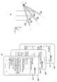
2 is a block diagram showing a main configuration of an electronic device according to an embodiment of the present invention.
3 is a block diagram illustrating a program module according to an embodiment of the present invention.
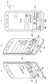
4 is a block diagram showing a main configuration of an electronic device according to an embodiment of the present invention.
5 is a flowchart illustrating an operation method of an electronic device according to an embodiment of the present invention.
6 is a flowchart illustrating a method of recognizing motion using gravity acceleration detected in an electronic device according to an exemplary embodiment of the present invention.
7 is a flowchart illustrating a method of recognizing motion using a rotation angle sensed by an electronic device according to an exemplary embodiment of the present invention.
8 is a flowchart illustrating a method of performing control using motion recognized in an electronic device according to an embodiment of the present invention.
9 is a flowchart illustrating an operation method of an application when an application is executed in an electronic device according to an embodiment of the present invention.
10 is a flowchart for explaining a motion recognition method in a running application according to an embodiment of the present invention.
11 is a diagram illustrating a screen for controlling a keypad according to a rotation angle of an electronic device according to an embodiment of the present invention.
12 is a diagram illustrating a screen for controlling a tab menu according to a rotation angle of an electronic device according to an embodiment of the present invention.
13 is a diagram illustrating a screen for controlling map data according to gravitational acceleration of an electronic device according to an embodiment of the present invention.
FIG. 14 is a diagram illustrating a screen for controlling a web page up and down according to gravitational acceleration of an electronic device according to an embodiment of the present invention.
FIG. 15 is a diagram illustrating a screen for controlling a web page to the left or right according to a gravitational acceleration of an electronic device according to an embodiment of the present invention.
16 is a diagram illustrating a screen for controlling brightness of a screen using user proximity information detected by an electronic device according to an exemplary embodiment of the present invention.
17 is a diagram illustrating a screen for performing a function according to a rotation angle of an electronic device when receiving a call according to an embodiment of the present invention.
18 is a diagram illustrating a screen for displaying a floating menu on an electronic device according to an embodiment of the present invention.
FIGS. 19 and 20 are diagrams for explaining a screen for controlling an application being executed according to a rotation angle of an electronic device according to an embodiment of the present invention.
FIG. 21 and FIG. 22 are diagrams illustrating screens for controlling a background screen according to a rotation angle of an electronic device according to an embodiment of the present invention.
23 is a diagram illustrating a screen for controlling call origination according to a rotation angle of an electronic device according to an embodiment of the present invention.
24 is a system diagram having an electronic device and an accessory device according to another embodiment of the present invention.
25 is a flowchart for explaining an operation for performing pairing with an accessory device in an electronic device according to another embodiment of the present invention.
26 is a flowchart for explaining an operation of performing pairing using the heartbeat information of the accessory device in the electronic device according to another embodiment of the present invention.
27 is a flowchart for explaining an operation of transferring heartbeat information from an accessory device to an electronic device to perform pairing according to another embodiment of the present invention.
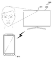
28 is a system diagram including an electronic device and an external electronic device according to another embodiment of the present invention.
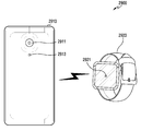
29 is a view for explaining positions of sensors provided in an electronic device and an accessory device according to another embodiment of the present invention.
Hereinafter, various embodiments of the present document will be described with reference to the accompanying drawings. It is to be understood that the embodiments and terminologies used herein are not intended to limit the invention to the particular embodiments described, but to include various modifications, equivalents, and / or alternatives of the embodiments. In connection with the description of the drawings, like reference numerals may be used for similar components. The singular expressions may include plural expressions unless the context clearly dictates otherwise. In this document, the expressions "A or B" or "at least one of A and / or B" and the like may include all possible combinations of the items listed together. Expressions such as " first, "" second," " first, "or" second, " But is not limited to those components. When it is mentioned that some (e.g., first) component is "(functionally or communicatively) connected" or "connected" to another (second) component, May be connected directly to the component, or may be connected through another component (e.g., a third component).
In this document, the term " configured to (or configured) to "as used herein is intended to encompass all types of hardware, software, , "" Made to "," can do ", or" designed to ". In some situations, the expression "a device configured to" may mean that the device can "do " with other devices or components. For example, a processor configured (or configured) to perform the phrases "A, B, and C" may be implemented by executing one or more software programs stored in a memory device or a dedicated processor (e.g., an embedded processor) , And a general purpose processor (e.g., a CPU or an application processor) capable of performing the corresponding operations.
Electronic devices in accordance with various embodiments of the present document may be used in various applications such as, for example, smart phones, tablet PCs, mobile phones, videophones, electronic book readers, desktop PCs, laptop PCs, netbook computers, workstations, a portable multimedia player, an MP3 player, a medical device, a camera, or a wearable device. Wearable devices may be of the type of accessories (eg, watches, rings, bracelets, braces, necklaces, glasses, contact lenses or head-mounted-devices (HMD) (E.g., a skin pad or tattoo), or a bio-implantable circuit. In some embodiments, the electronic device may be, for example, a television, a digital video disk (Eg Samsung HomeSyncTM, Apple TVTM, or Google TVTM), game consoles, home appliances, air conditioners, air conditioners, refrigerators, air conditioners, vacuum cleaners, ovens, microwaves, washing machines, air cleaners, set top boxes, home automation control panels, (E.g., Xbox (TM), PlayStation (TM)), an electronic dictionary, an electronic key, a camcorder, or an electronic photo frame.
In an alternative embodiment, the electronic device may be any of a variety of medical devices (e.g., various portable medical measurement devices such as a blood glucose meter, a heart rate meter, a blood pressure meter, or a body temperature meter), magnetic resonance angiography (MRA) A navigation system, a global navigation satellite system (GNSS), an event data recorder (EDR), a flight data recorder (FDR), an automobile infotainment device, a marine electronic equipment (For example, marine navigation systems, gyro compasses, etc.), avionics, security devices, head units for vehicles, industrial or domestic robots, drones, ATMs at financial institutions, of at least one of the following types of devices: a light bulb, a fire detector, a fire alarm, a thermostat, a streetlight, a toaster, a fitness device, a hot water tank, a heater, a boiler, . According to some embodiments, the electronic device may be a piece of furniture, a building / structure or part of an automobile, an electronic board, an electronic signature receiving device, a projector, or various measuring devices (e.g., Gas, or radio wave measuring instruments, etc.). In various embodiments, the electronic device is flexible or may be a combination of two or more of the various devices described above. The electronic device according to the embodiment of the present document is not limited to the above-described devices. In this document, the term user may refer to a person using an electronic device or a device using an electronic device (e.g., an artificial intelligence electronic device).
Referring to Figure 1, in various embodiments, an electronic device 101 in a
The
The
The wireless communication may include, for example, LTE, LTE-A (LTE Advance), code division multiple access (CDMA), wideband CDMA (WCDMA), universal mobile telecommunications system (UMTS), wireless broadband (WiBro) System for Mobile Communications), and the like. According to one embodiment, the wireless communication may be wireless communication, such as wireless fidelity (WiFi), Bluetooth, Bluetooth low power (BLE), Zigbee, NFC, Magnetic Secure Transmission, Frequency (RF), or body area network (BAN). According to one example, wireless communication may include GNSS. GNSS may be, for example, Global Positioning System (GPS), Global Navigation Satellite System (Glonass), Beidou Navigation Satellite System (Beidou) or Galileo, the European global satellite-based navigation system. Hereinafter, in this document, " GPS " can be used interchangeably with " GNSS ". The wired communication may include, for example, at least one of a universal serial bus (USB), a high definition multimedia interface (HDMI), a recommended standard 232 (RS-232), a power line communication or a plain old telephone service have.
Each of the first and second external
2 is a block diagram of an electronic device 201 according to various embodiments. The electronic device 201 may include all or part of the electronic device 101 shown in Fig. 1, for example. The electronic device 201 may include one or more processors (e.g., AP) 210, a communications module 220, a
May have the same or similar configuration as communication module 220 (e.g., communication interface 170). The communication module 220 may include, for example, a cellular module 221, a
Memory 230 (e.g., memory 130) may include, for example, internal memory 232 or external memory 234. Volatile memory (e.g., a DRAM, an SRAM, or an SDRAM), a non-volatile memory (e.g., an OTPROM, a PROM, an EPROM, an EEPROM, a mask ROM, a flash ROM , A flash memory, a hard drive, or a solid state drive (SSD). The external memory 234 may be a flash drive, for example, a compact flash (CF) ), Micro-SD, Mini-SD, extreme digital (xD), multi-media card (MMC), or memory stick, etc. External memory 234 may communicate with electronic device 201, Or may be physically connected.
The
The input device 250 may include, for example, a touch panel 252, a (digital) pen sensor 254, a key 256, or an
Display 260 (e.g., display 160) may include panel 262, hologram device 264, projector 266, and / or control circuitry for controlling them. The panel 262 may be embodied, for example, flexibly, transparently, or wearably. The panel 262 may comprise a touch panel 252 and one or more modules. The hologram device 264 can display a stereoscopic image in the air using interference of light. The projector 266 can display an image by projecting light onto a screen. The screen may be located, for example, inside or outside the electronic device 201. The interface 270 may include, for example, an
The audio module 280 can, for example, convert sound and electrical signals in both directions. At least some of the components of the audio module 280 may be included, for example, in the input /
The
3 is a block diagram of a program module according to various embodiments. According to one embodiment, program module 310 (e.g., program 140) includes an operating system that controls resources associated with an electronic device (e.g., electronic device 101) and / E.g., an application program 147). The operating system may include, for example, AndroidTM, iOSTM, WindowsTM, SymbianTM, TizenTM, or BadaTM. 3,
The kernel 320 may include, for example, a system resource manager 321 and / or a device driver 323. The system resource manager 321 can perform control, allocation, or recovery of system resources. According to one embodiment, the system resource manager 321 may include a process manager, a memory manager, or a file system manager. The device driver 323 may include, for example, a display driver, a camera driver, a Bluetooth driver, a shared memory driver, a USB driver, a keypad driver, a WiFi driver, an audio driver, or an inter-process communication . The middleware 330 may provide various functions through the
The
The connectivity manager 348 may, for example, manage the wireless connection. The notification manager 349 may provide the user with an event such as, for example, an arrival message, an appointment, a proximity notification, and the like. The location manager 350 can manage the location information of the electronic device, for example. The graphic manager 351 may, for example, manage the graphical effects to be presented to the user or a user interface associated therewith. Security manager 352 may provide, for example, system security or user authentication. According to one embodiment, the middleware 330 may include a telephony manager for managing the voice or video call function of the electronic device, or a middleware module capable of forming a combination of the functions of the above-described components . According to one embodiment, the middleware 330 may provide a module specialized for each type of operating system. Middleware 330 may dynamically delete some existing components or add new ones. The
The application 370 may include a home 371, a
As used herein, the term "module " includes units comprised of hardware, software, or firmware and may be used interchangeably with terms such as, for example, logic, logic blocks, components, or circuits. A "module" may be an integrally constructed component or a minimum unit or part thereof that performs one or more functions. "Module" may be implemented either mechanically or electronically, for example, by application-specific integrated circuit (ASIC) chips, field-programmable gate arrays (FPGAs) And may include programmable logic devices. At least some of the devices (e.g., modules or functions thereof) or methods (e.g., operations) according to various embodiments may be stored in a computer readable storage medium (e.g., memory 130) . ≪ / RTI > When the instruction is executed by a processor (e.g., processor 120), the processor may perform a function corresponding to the instruction. The computer-readable recording medium may be a hard disk, a floppy disk, a magnetic medium such as a magnetic tape, an optical recording medium such as a CD-ROM, a DVD, a magnetic-optical medium such as a floppy disk, The instructions may include code that is generated by the compiler or code that may be executed by the interpreter. Modules or program modules according to various embodiments may include at least one or more of the components described above Operations that are performed by modules, program modules, or other components, in accordance with various embodiments, may be performed in a sequential, parallel, iterative, or heuristic manner, or at least in part Some operations may be executed in a different order, omitted, or other operations may be added.
4 is a block diagram showing a main configuration of an electronic device according to an embodiment of the present invention.
4, an
The
The sensor unit 420 may sense the operation of the user and transmit the obtained sensing information to the processor 480. The sensor unit 420 may include a
The
The image processing unit 440 can process image data. The image processing unit 440 processes the image data on a frame-by-frame basis, and outputs the image data in correspondence with the feature and size of the
The
The input unit 460 can generate input data in the
The memory 470 may store operational programs of the
The processor 480 may control the overall operation of the
The processor 480 can detect proximity of a specific object through the proximity sensor 422 or the
Z-axis rotation detection: Rotating north, east, west and north
Z-axis rotation detection: keyboard type change
x-axis rotation detection: Display the telephone rejection message screen
Scroll: Select call reject message
x axis rotation detection: Open top tab menu / Open Task manager screen
The processor 480 may transmit sensing information, such as heartbeat information, temperature information, vein information, etc., obtained through the
The
The processor 480 may be configured to change at least a portion of the user interface based on the rate, direction, size or amount of movement.
The processor 480 may be configured to move at least one content in a direction corresponding to the direction based on the direction of movement.
When the motion value satisfies the first condition, the processor 480 executes the first function corresponding to the motion, and when the motion value satisfies the second condition, executes the second function corresponding to the motion value Can be set.
The processor 480 may be configured to perform at least one function while the proximity of the user is sensed using the sensor.
The processor 480 may be configured to perform a third function if proximity of the user is not sensed using the sensor.
And a
Processor 480 may be configured to activate at least one
The processor 480 may be configured to identify the functions assigned to the motion obtained at the
The processor 480 may be configured to perform at least one of functions of scrolling screen data, moving a partial area of screen data, enlarging and reducing screen data, and changing a menu in an application based on the motion.
The processor 480 can be set to maintain the brightness of the
The processor 480 may be configured to activate the sensor if the application is an application that operates in conjunction with the sensor.
The living
5 is a flowchart illustrating an operation method of an electronic device according to an embodiment of the present invention.
Referring to FIG. 5, the electronic device 400 (e.g., the processor 480) in 501 operation may display on the
The electronic device 400 (e.g., processor 480) in 505 operation can activate the motion sensor 421 (e. G., The processor 480) have. In
In
The electronic device 400 (e.g., processor 480) may return to
6 is a flowchart illustrating a method of recognizing motion using gravity acceleration detected in an electronic device according to an exemplary embodiment of the present invention.
6, if the
In
7 is a flowchart illustrating a method of recognizing motion using a rotation angle sensed by an electronic device according to an exemplary embodiment of the present invention.
7, if the
In
8 is a flowchart illustrating a method of performing control using motion recognized in an electronic device according to an embodiment of the present invention.
8, in an
In operation 803, the electronic device 400 (e.g., processor 480) may identify the function assigned to the motion. For example, the electronic device 400 (e.g., processor 480) may verify the function assigned to the amount of change in gravitational acceleration that exceeds the threshold. In addition, the electronic device 400 (e.g., processor 480) may identify the function assigned to the amount of change in the rotational angle that exceeds the threshold. In operation 805, the electronic device 400 (e.g., processor 480) may perform 807 operations if the function assigned to the motion exists.
In operation 807, the electronic device 400 (e.g., processor 480) may perform a function assigned to the motion (e.g., a first function or a second function). For example, the function assigned to the motion may include event control such as zooming in / zooming out of screen data displayed on the
9 is a flowchart illustrating an operation method of an application when an application is executed in an electronic device according to an embodiment of the present invention.
According to one embodiment, referring to FIG. 9, an electronic device 400 (e.g., processor 480) in 901 operation may receive an application execution signal. In
The electronic device 400 (e.g., the processor 480) may perform the
In operation, the electronic device 400 (e.g., processor 480) may activate proximity sensor 422 or
In 911 operation, the electronic device 400 (e.g., processor 480) may activate the sensor. For example, electronic device 400 (e.g., processor 480) may activate
In
10 is a flowchart for explaining a motion recognition method in a running application according to an embodiment of the present invention.
According to one embodiment, referring to FIG. 10, an electronic device 400 (e.g., processor 480) in 1001 operation may perform 1003 operations when the
In
11 is a diagram illustrating a screen for controlling a keypad according to a rotation angle of an electronic device according to an embodiment of the present invention.
11, an electronic device 400 (e.g., processor 480) may execute an application that may display a keypad for inputting a telephone number on the
The electronic device 400 (e.g., processor 480) may determine a first rotation angle with respect to the x-, y-, and z-axes in the state of Figure 11 (a) by a
The electronic device 400 (e.g., the processor 480) can confirm that the
The electronic device 400 (e.g., the processor 480) can confirm that the
12 is a diagram illustrating a screen for controlling a tab menu according to a rotation angle of an electronic device according to an embodiment of the present invention.
12, an electronic device 400 (e.g., processor 480) executes an application store and displays screen data corresponding to the application store on a display unit (not shown) as shown in FIG. 12 (a) 450). ≪ / RTI > The screen data may be screen data in a state where the
The electronic device 400 (e.g., the processor 480)) confirms the first rotational angle when in the state of Figure 12 (a) by the
The electronic device 400 (e.g., the processor 480)) can determine that the electronic device 400 (e.g., processor 480) is rotated about the y axis, have. The electronic device 400 (e.g., the processor 480)) is configured such that the electronic device 400 (e.g., the processor 480) is rotated left when the
The electronic device 400 (e.g., the processor 480) can confirm that the electronic device 400 (e.g., the processor 480) is rotated with respect to the y axis as shown in FIG. 12 (c) . The electronic device 400 (e.g., the processor 480)) is configured to cause the electronic device 400 (e.g., the processor 480) to rotate clockwise with the
13 is a diagram illustrating a screen for controlling map data according to gravitational acceleration of an electronic device according to an embodiment of the present invention.
13, the electronic device 400 (e.g., the processor 480) executes an application that displays map data and generates map data corresponding to the application as shown in FIG. 13 (a) Can be displayed on the
The electronic device 400 (e.g., the processor 480) may determine a first acceleration magnitude for the x-, y-, and z-axes in the state of Figure 13 (a) by the
The electronic device 400 (e.g., the processor 480) can confirm that the electronic device moves in the z-axis, moving in the direction of 1, and away from the user, as shown in FIG. 13 (b). The electronic device 400 (e.g., the processor 480)) determines whether the electronic device 400 (e.g., the processor 480) is away from the user in a state where map data having a specific scale is displayed as shown in FIG. , It is possible to convert the map data into a map data with a specific scale, as shown in Fig. 13 (b), and display the map data.
The electronic device 400 (e.g., the processor 480) can confirm that the electronic device moves in the z axis, moving in the direction of 0 as shown in (c) of FIG. The electronic device 400 (for example, the processor 480)), when the
FIG. 14 is a diagram illustrating a screen for controlling a web page up and down according to gravitational acceleration of an electronic device according to an embodiment of the present invention.
14, with the user gripping the
The electronic device 400 (e.g., the processor 480) is configured to detect an x-axis of the
The electronic device 400 (e.g., the processor 480) can confirm that the
The electronic device 400 (e.g., the processor 480) can confirm that the
14, the
The electronic device 400 (e.g., processor 480) may determine a second rotation angle relative to the x axis of the electronic device 400 (e.g., processor 480) in which the motion has occurred. The electronic device 400 (e.g., processor 480) may calculate the rate of change of the first rotational angle and the second rotational angle. The electronic device 400 (e.g., processor 480) may perform a function corresponding to the detected motion when the rate of change exceeds a threshold. The electronic device 400 (e.g., the processor 480) can scroll the
FIG. 15 is a diagram illustrating a screen for controlling a web page to the left or right according to a gravitational acceleration of an electronic device according to an embodiment of the present invention.
15, with the user gripping the
The electronic device 400 (e.g., the processor 480)) detects the
The electronic device 400 (e.g., the processor 480) can confirm that the
The electronic device 400 (for example, the processor 480) can confirm that the movement of the
In the example shown in FIG. 15, the
The electronic device 400 (e.g., processor 480) can determine the second rotation angle with respect to the y-axis of the electronic device 400 (e.g., processor 480) in which the motion has occurred. The electronic device 400 (e.g., processor 480) may calculate the rate of change of the first rotational angle and the second rotational angle. The electronic device 400 (e.g., processor 480) may perform a function corresponding to the detected motion when the rate of change exceeds a threshold. The electronic device 400 (e.g., the processor 480) can scroll the
16 is a diagram illustrating a screen for controlling brightness of a screen using user proximity information detected by an electronic device according to an exemplary embodiment of the present invention.
16, the electronic device 400 (e.g., the processor 480) executes a specific application and displays screen data for the application on the
17 is a diagram illustrating a screen for performing a function according to a rotation angle of an electronic device when receiving a call according to an embodiment of the present invention.
17, the electronic device 400 (e.g., the processor 480) may display screen data as shown in FIG. 17 (a) on the
The electronic device 400 (e.g., processor 480) may determine the first rotational angle when in the state of Figure 17 (a) by
The electronic device 400 (e.g., the processor 480) can confirm that the
The electronic device 400 (e.g., the processor 480) can confirm that the
18 is a diagram illustrating a screen for displaying a floating menu on an electronic device according to an embodiment of the present invention.
Referring to FIG. 18, an electronic device 400 (e.g., processor 480) may display screen data for an application related to a message on the
The electronic device 400 (e.g., processor 480) may display the floating
FIGS. 19 and 20 are diagrams for explaining a screen for controlling an application being executed according to a rotation angle of an electronic device according to an embodiment of the present invention.
19 and 20, the electronic device 400 (e.g., the processor 480) can display screen data for a specific application on the
The electronic device 400 (e.g., the processor 480)) confirms the first rotational angle of the
The electronic device 400 (e.g., the processor 480) can confirm that the
The electronic device 400 (e.g., the processor 480) can confirm that the
According to one embodiment, the electronic device 400 (e.g., the processor 480) may display the screen data for a specific application on the
The electronic device 400 (e.g., processor 480) may determine the first rotational angle when in motion (a) of Figure 20 by
The electronic device 400 (e.g., the processor 480) may be configured such that when the proximity sensor 422 or the
FIG. 21 and FIG. 22 are diagrams illustrating screens for controlling a background screen according to a rotation angle of an electronic device according to an embodiment of the present invention.
21 and 22, the electronic device 400 (e.g., the processor 480) can display a standby screen on the
The electronic device 400 (e.g., processor 480)) can see that the electronic device 400 (e.g., processor 480) is rotated about the y axis, but rotated to the left, as shown in Figure 21 (b) have. When the
According to one embodiment, the electronic device 400 (e.g., processor 480) can display a standby screen on the
The electronic device 400 (e.g., the processor 480)) can see that the electronic device 400 (e.g., the processor 480) is rotated about the x axis but is rotated downward as shown in Figure 22 (b) have. The electronic device 400 (e.g., the processor 480) can display a notification window on the
The electronic device 400 (e.g., processor 480)) can determine that the electronic device 400 (e.g., processor 480) is rotated about the x axis but is rotated downward as shown in Figure 22C have. The electronic device 400 (e.g., the processor 480) can display a list of recently executed applications on the
23 is a diagram illustrating a screen for controlling call origination according to a rotation angle of an electronic device according to an embodiment of the present invention.
23, the electronic device 400 (e.g., processor 480) may display a call list screen on the
The electronic device 400 (e.g., processor 480)) can determine that the electronic device 400 (e.g., the processor 480) is rotated about the y axis, but rotated leftward as shown in Figure 23 (b) have. When the
The electronic device 400 (e.g., the processor 480) can originate a call to a specific party included in the screen data if proximity of the user is confirmed through another
In the embodiment of the present invention, the operation method of the
The operation of displaying the screen data may be an operation of displaying screen data for the application being executed. The operation of displaying the screen data may further include an operation of confirming that the application is an application that operates in conjunction with the sensor, and an operation of activating the sensor.
The motion sensing action may include activating the
The operation of executing at least one function may include an operation of confirming whether or not the function corresponding to the calculated change value exists, and an operation of executing the function when the function exists.
The operation for executing the function includes an operation of performing at least one of functions of scrolling screen data, moving a part of screen data, enlarging / reducing screen data, and changing a menu in an application based on the change value .
The operation of executing at least one function may include an operation of controlling the brightness of the
24 is a system diagram having an electronic device and an accessory device according to another embodiment of the present invention.
According to one embodiment, referring to FIG. 24, a
The
The electronic device 2410 (e.g., processor 480) compares the heartbeat information obtained at the
The
25 is a flowchart for explaining an operation for performing pairing with an accessory device in an electronic device according to another embodiment of the present invention.
25, in a 2501 operation, an electronic device 2410 (e.g., an electronic device 400 (e.g., processor 480)) performs a 2503 operation upon receiving a pairing request signal from a user with an
As a result of the determination of the 2503 operation, the electronic device 2410 (e.g., processor 480) may perform the 2505 operation if the pairing with the
The electronic device 2410 (e.g., processor 480) is coupled to the display (e.g., display 450) of the electronic device 2410 (e.g., processor 480) via interfacing with the paired
26 is a flowchart for explaining an operation of performing pairing using the heartbeat information of the accessory device in the electronic device according to another embodiment of the present invention.
26, an electronic device 2410 (e.g., processor 480) in 2601 operation may activate near field communication to receive heartbeat information from an
In an
In
27 is a flowchart for explaining an operation of transferring heartbeat information from an accessory device to an electronic device to perform pairing according to another embodiment of the present invention.
Referring to FIG. 27, in 2701 operation,
As a result of the confirmation of
In
28 is a system diagram including an electronic device and an external electronic device according to another embodiment of the present invention.
28, a
The
The electronic device 2810 (e.g., processor 480) may compare the heartbeat information obtained at the
The
29 is a view for explaining positions of sensors provided in an electronic device and an accessory device according to another embodiment of the present invention.
29, a
The electronic device 2910 (e.g., processor 480) may perform the pairing with the
The
It should be noted that the embodiments of the present invention disclosed in the present specification and drawings are only illustrative of the present invention in order to facilitate the understanding of the present invention and are not intended to limit the scope of the present invention. That is, it will be apparent to those skilled in the art that other modifications based on the technical idea of the present invention are possible.
Claims (21)
A sensor of at least one of a proximity sensor and a biosensor;
Motion sensor; And
The processor comprising:
Using the sensor to confirm the proximity of the user corresponding to the electronic device,
Acquiring a motion value corresponding to a motion of the electronic device through the motion sensor based on the confirmation; and
And to perform at least one function using the motion value.
The processor comprising:
And change at least a portion of the user interface based on the speed, direction, size or amount of movement of the movement.
The processor comprising:
And move at least one content in a direction corresponding to the direction based on the direction of the movement.
The processor comprising:
An electronic control unit configured to execute a first function corresponding to the motion when the motion value satisfies a first condition and to execute a second function corresponding to the motion value when the motion value satisfies a second condition, Device.
The processor comprising:
And perform the at least one function while the proximity of the user is sensed using the sensor.
The processor comprising:
And to perform a third function if proximity of the user is not detected using the sensor.
Further comprising a display unit,
The processor comprising:
And display screen data for a running application on the display unit.
The processor comprising:
And to activate at least one motion sensor capable of acquiring the motion value if proximity of the user is identified.
The processor comprising:
Wherein the electronic device is configured to confirm the function assigned to the motion obtained from the motion sensor and to perform the identified function.
The processor comprising:
And to perform at least one of scrolling the screen data based on the movement, moving a part of the screen data, enlarging or reducing the screen data, and changing the menu in the application.
The processor comprising:
And to maintain the brightness of the display unit even after a lapse of a critical time if the motion is not obtained in the motion sensor.
The processor comprising:
And if the application is an application operating in conjunction with the sensor, activate the sensor.
Wherein the biosensor includes at least one of a heart rate sensor, a temperature sensor, and a vein sensor,
The processor comprising:
And to perform pairing with an external electronic device using at least one of heartbeat information, temperature information, and vein information sensed by the bio-sensor.
An operation of displaying screen data;
Confirming the proximity of the user through at least one of the proximity sensor and the biosensor;
Detecting movement of the electronic device through the motion sensor when the proximity of the user is confirmed; And
Performing at least one function corresponding to the motion;
≪ / RTI >
The operation of displaying the screen data includes:
And displaying screen data for the running application.
The operation of displaying the screen data includes:
Confirming whether the application is an application operating in conjunction with the sensor;
Activating the sensor;
≪ / RTI >
The motion detection may include:
Activating the motion sensor if proximity of the user is identified;
≪ / RTI >
The motion detection may include:
Checking the first sensing information when the motion sensor is activated;
Confirming second sensing information corresponding to the motion when the motion is detected;
Calculating a change value for the first sensing information and the second sensing information;
≪ / RTI >
Wherein the act of performing the at least one function comprises:
Confirming whether or not the function corresponding to the calculated change value exists;
Performing the function if the function exists;
≪ / RTI >
The operation for executing the function may include:
Performing at least one of scrolling the screen data, moving a part of the screen data, enlarging and reducing the screen data, and changing a menu in the application based on the change value;
≪ / RTI >
Wherein the act of performing the at least one function comprises:
Controlling the brightness of the display unit on which the screen data is displayed even after the lapse of the threshold time if the function is not present;
≪ / RTI >
Priority Applications (3)
| Application Number | Priority Date | Filing Date | Title |
|---|---|---|---|
| KR1020160003738A KR20170084558A (en) | 2016-01-12 | 2016-01-12 | Electronic Device and Operating Method Thereof |
| US15/403,354 US20170199588A1 (en) | 2016-01-12 | 2017-01-11 | Electronic device and method of operating same |
| US16/263,142 US20190163286A1 (en) | 2016-01-12 | 2019-01-31 | Electronic device and method of operating same |
Applications Claiming Priority (1)
| Application Number | Priority Date | Filing Date | Title |
|---|---|---|---|
| KR1020160003738A KR20170084558A (en) | 2016-01-12 | 2016-01-12 | Electronic Device and Operating Method Thereof |
Publications (1)
| Publication Number | Publication Date |
|---|---|
| KR20170084558A true KR20170084558A (en) | 2017-07-20 |
Family
ID=59275660
Family Applications (1)
| Application Number | Title | Priority Date | Filing Date |
|---|---|---|---|
| KR1020160003738A KR20170084558A (en) | 2016-01-12 | 2016-01-12 | Electronic Device and Operating Method Thereof |
Country Status (2)
| Country | Link |
|---|---|
| US (2) | US20170199588A1 (en) |
| KR (1) | KR20170084558A (en) |
Cited By (2)
| Publication number | Priority date | Publication date | Assignee | Title |
|---|---|---|---|---|
| WO2019139409A1 (en) * | 2018-01-12 | 2019-07-18 | 삼성전자 주식회사 | Method and electronic device for correcting and generating data related to outside air on basis of movement |
| US20220022139A1 (en) * | 2018-12-26 | 2022-01-20 | Huizhou Tcl Mobile Communication Co., Ltd. | Control method for doze mode of mobile terminal, storage medium and mobile terminal |
Families Citing this family (7)
| Publication number | Priority date | Publication date | Assignee | Title |
|---|---|---|---|---|
| US9754093B2 (en) * | 2014-08-28 | 2017-09-05 | Ncr Corporation | Methods and a system for automated authentication confidence |
| US9906954B2 (en) | 2014-10-20 | 2018-02-27 | Payfone, Inc. | Identity authentication |
| US11368454B2 (en) * | 2016-05-19 | 2022-06-21 | Prove Identity, Inc. | Implicit authentication for unattended devices that need to identify and authenticate users |
| US11176231B2 (en) | 2016-05-19 | 2021-11-16 | Payfone, Inc. | Identifying and authenticating users based on passive factors determined from sensor data |
| US10735653B1 (en) * | 2017-03-14 | 2020-08-04 | Ambarella International Lp | Electronic image stabilization to improve video analytics accuracy |
| JP6802398B2 (en) * | 2019-02-28 | 2020-12-16 | シチズン時計株式会社 | Portable electronic device |
| EP3779612A1 (en) * | 2019-08-16 | 2021-02-17 | The Swatch Group Research and Development Ltd | Method for broadcasting a message to the wearer of a watch |
Family Cites Families (25)
| Publication number | Priority date | Publication date | Assignee | Title |
|---|---|---|---|---|
| US8564544B2 (en) * | 2006-09-06 | 2013-10-22 | Apple Inc. | Touch screen device, method, and graphical user interface for customizing display of content category icons |
| US20090265671A1 (en) * | 2008-04-21 | 2009-10-22 | Invensense | Mobile devices with motion gesture recognition |
| US8390649B2 (en) * | 2007-04-30 | 2013-03-05 | Hewlett-Packard Development Company, L.P. | Electronic device input control system and method |
| US8174483B2 (en) * | 2008-02-20 | 2012-05-08 | Computime, Ltd. | Automatic display unit activation |
| JP4571198B2 (en) * | 2008-03-07 | 2010-10-27 | 京セラ株式会社 | Mobile communication terminal |
| KR101505198B1 (en) * | 2008-08-18 | 2015-03-23 | 엘지전자 주식회사 | PORTABLE TERMINAL and DRIVING METHOD OF THE SAME |
| KR101737829B1 (en) * | 2008-11-10 | 2017-05-22 | 삼성전자주식회사 | Motion Input Device For Portable Device And Operation Method using the same |
| KR101568128B1 (en) * | 2008-11-14 | 2015-11-12 | 삼성전자주식회사 | Method for operating user interface based on motion sensor and mobile terminal using the same |
| KR101545876B1 (en) * | 2009-01-22 | 2015-08-27 | 삼성전자주식회사 | Method for power saving based on motion sensor and mobile terminal using the same |
| UY32748A (en) * | 2009-07-02 | 2011-01-31 | Novartis Ag | 2-CARBOXAMIDA-CICLOAMINO-UREAS |
| US8717291B2 (en) * | 2009-10-07 | 2014-05-06 | AFA Micro Co. | Motion sensitive gesture device |
| US8525688B2 (en) * | 2011-01-10 | 2013-09-03 | Palm, Inc. | Proximity detection alarm for an inductively charged mobile computing device |
| US20130033418A1 (en) * | 2011-08-05 | 2013-02-07 | Qualcomm Incorporated | Gesture detection using proximity or light sensors |
| JP2013084029A (en) * | 2011-10-06 | 2013-05-09 | Sony Corp | Display control device |
| US8863042B2 (en) * | 2012-01-24 | 2014-10-14 | Charles J. Kulas | Handheld device with touch controls that reconfigure in response to the way a user operates the device |
| US20140019194A1 (en) * | 2012-07-12 | 2014-01-16 | Bank Of America | Predictive Key Risk Indicator Identification Process Using Quantitative Methods |
| US10216266B2 (en) * | 2013-03-14 | 2019-02-26 | Qualcomm Incorporated | Systems and methods for device interaction based on a detected gaze |
| US10067634B2 (en) * | 2013-09-17 | 2018-09-04 | Amazon Technologies, Inc. | Approaches for three-dimensional object display |
| KR20160065920A (en) * | 2013-11-29 | 2016-06-09 | 인텔 코포레이션 | Controlling a camera with face detection |
| KR102206385B1 (en) * | 2014-04-11 | 2021-01-22 | 엘지전자 주식회사 | Mobile terminal and method for controlling the same |
| KR102229699B1 (en) * | 2014-05-22 | 2021-03-18 | 삼성전자주식회사 | Method and Electronic Device for Information |
| US20160036996A1 (en) * | 2014-08-02 | 2016-02-04 | Sony Corporation | Electronic device with static electric field sensor and related method |
| KR102269797B1 (en) * | 2014-10-08 | 2021-06-28 | 엘지전자 주식회사 | Wearable device |
| KR102320895B1 (en) * | 2015-04-01 | 2021-11-03 | 엘지전자 주식회사 | Mobile terminal and method for controlling the same |
| US10416802B2 (en) * | 2015-09-14 | 2019-09-17 | Stmicroelectronics Asia Pacific Pte Ltd | Mutual hover protection for touchscreens |
-
2016
- 2016-01-12 KR KR1020160003738A patent/KR20170084558A/en unknown
-
2017
- 2017-01-11 US US15/403,354 patent/US20170199588A1/en not_active Abandoned
-
2019
- 2019-01-31 US US16/263,142 patent/US20190163286A1/en not_active Abandoned
Cited By (4)
| Publication number | Priority date | Publication date | Assignee | Title |
|---|---|---|---|---|
| WO2019139409A1 (en) * | 2018-01-12 | 2019-07-18 | 삼성전자 주식회사 | Method and electronic device for correcting and generating data related to outside air on basis of movement |
| US11549927B2 (en) | 2018-01-12 | 2023-01-10 | Samsung Electronics Co., Ltd. | Method and electronic device for correcting and generating data related to outside air on basis of movement |
| US20220022139A1 (en) * | 2018-12-26 | 2022-01-20 | Huizhou Tcl Mobile Communication Co., Ltd. | Control method for doze mode of mobile terminal, storage medium and mobile terminal |
| US11832189B2 (en) * | 2018-12-26 | 2023-11-28 | Huizhou Tcl Mobile Communication Co., Ltd. | Control method for doze mode of mobile terminal, storage medium and mobile terminal |
Also Published As
| Publication number | Publication date |
|---|---|
| US20190163286A1 (en) | 2019-05-30 |
| US20170199588A1 (en) | 2017-07-13 |
Similar Documents
| Publication | Publication Date | Title |
|---|---|---|
| EP3086217B1 (en) | Electronic device for displaying screen and control method thereof | |
| EP3358455A1 (en) | Apparatus and method for controlling fingerprint sensor | |
| KR102503937B1 (en) | Apparatus and method for providing user interface of electronic device | |
| KR102485448B1 (en) | Electronic device and method for processing gesture input | |
| KR20170084558A (en) | Electronic Device and Operating Method Thereof | |
| KR102547115B1 (en) | Method for switching application and electronic device thereof | |
| EP3367282B1 (en) | Electronic device for authenticating using biometric information and method of operating electronic device | |
| CN107835969B (en) | Electronic device including touch sensing module and method of operating the same | |
| KR102324964B1 (en) | Electronic device and method for processing input of external input device | |
| US20170220137A1 (en) | User interfacing method and electronic device for performing the same | |
| EP3086218A1 (en) | Method and electronic device for providing user interface | |
| EP3200058A1 (en) | Electronic device and method for processing input on view layers | |
| US20160253047A1 (en) | Method for operating electronic device, electronic device, and storage medium | |
| EP3125101A1 (en) | Screen controlling method and electronic device for supporting the same | |
| KR102513147B1 (en) | Electronic device and method for recognizing touch input using the same | |
| KR20180014614A (en) | Electronic device and method for processing touch event thereof | |
| US20170097751A1 (en) | Electronic device for providing one-handed user interface and method therefor | |
| KR20170027118A (en) | Method and apparatus for connecting with external device | |
| KR20180051002A (en) | Method for cotrolling launching of an application in a electronic device using a touch screen and the electronic device thereof | |
| KR20180009147A (en) | Method for providing user interface using force input and electronic device for the same | |
| KR102630789B1 (en) | Electric device and method for processing touch input | |
| KR20180052951A (en) | Method for providing object information and electronic device thereof | |
| KR102553573B1 (en) | Electronic device and method for detecting touch input of the same | |
| KR20180127831A (en) | Electronic device and method for sharing information of the same | |
| CN108427529B (en) | Electronic device and operation method thereof |