KR20170072637A - Video Coding/Encoding Method and Apparatus thereof - Google Patents
Video Coding/Encoding Method and Apparatus thereof Download PDFInfo
- Publication number
- KR20170072637A KR20170072637A KR1020150181056A KR20150181056A KR20170072637A KR 20170072637 A KR20170072637 A KR 20170072637A KR 1020150181056 A KR1020150181056 A KR 1020150181056A KR 20150181056 A KR20150181056 A KR 20150181056A KR 20170072637 A KR20170072637 A KR 20170072637A
- Authority
- KR
- South Korea
- Prior art keywords
- mode
- block
- inter
- prediction
- merge
- Prior art date
Links
Images


Classifications
-
- H—ELECTRICITY
- H04—ELECTRIC COMMUNICATION TECHNIQUE
- H04N—PICTORIAL COMMUNICATION, e.g. TELEVISION
- H04N19/00—Methods or arrangements for coding, decoding, compressing or decompressing digital video signals
- H04N19/10—Methods or arrangements for coding, decoding, compressing or decompressing digital video signals using adaptive coding
- H04N19/102—Methods or arrangements for coding, decoding, compressing or decompressing digital video signals using adaptive coding characterised by the element, parameter or selection affected or controlled by the adaptive coding
- H04N19/103—Selection of coding mode or of prediction mode
- H04N19/105—Selection of the reference unit for prediction within a chosen coding or prediction mode, e.g. adaptive choice of position and number of pixels used for prediction
-
- H—ELECTRICITY
- H04—ELECTRIC COMMUNICATION TECHNIQUE
- H04N—PICTORIAL COMMUNICATION, e.g. TELEVISION
- H04N19/00—Methods or arrangements for coding, decoding, compressing or decompressing digital video signals
- H04N19/10—Methods or arrangements for coding, decoding, compressing or decompressing digital video signals using adaptive coding
- H04N19/134—Methods or arrangements for coding, decoding, compressing or decompressing digital video signals using adaptive coding characterised by the element, parameter or criterion affecting or controlling the adaptive coding
- H04N19/146—Data rate or code amount at the encoder output
- H04N19/147—Data rate or code amount at the encoder output according to rate distortion criteria
-
- H—ELECTRICITY
- H04—ELECTRIC COMMUNICATION TECHNIQUE
- H04N—PICTORIAL COMMUNICATION, e.g. TELEVISION
- H04N19/00—Methods or arrangements for coding, decoding, compressing or decompressing digital video signals
- H04N19/10—Methods or arrangements for coding, decoding, compressing or decompressing digital video signals using adaptive coding
- H04N19/102—Methods or arrangements for coding, decoding, compressing or decompressing digital video signals using adaptive coding characterised by the element, parameter or selection affected or controlled by the adaptive coding
- H04N19/103—Selection of coding mode or of prediction mode
- H04N19/107—Selection of coding mode or of prediction mode between spatial and temporal predictive coding, e.g. picture refresh
-
- H—ELECTRICITY
- H04—ELECTRIC COMMUNICATION TECHNIQUE
- H04N—PICTORIAL COMMUNICATION, e.g. TELEVISION
- H04N19/00—Methods or arrangements for coding, decoding, compressing or decompressing digital video signals
- H04N19/10—Methods or arrangements for coding, decoding, compressing or decompressing digital video signals using adaptive coding
- H04N19/102—Methods or arrangements for coding, decoding, compressing or decompressing digital video signals using adaptive coding characterised by the element, parameter or selection affected or controlled by the adaptive coding
- H04N19/103—Selection of coding mode or of prediction mode
- H04N19/109—Selection of coding mode or of prediction mode among a plurality of temporal predictive coding modes
-
- H—ELECTRICITY
- H04—ELECTRIC COMMUNICATION TECHNIQUE
- H04N—PICTORIAL COMMUNICATION, e.g. TELEVISION
- H04N19/00—Methods or arrangements for coding, decoding, compressing or decompressing digital video signals
- H04N19/10—Methods or arrangements for coding, decoding, compressing or decompressing digital video signals using adaptive coding
- H04N19/102—Methods or arrangements for coding, decoding, compressing or decompressing digital video signals using adaptive coding characterised by the element, parameter or selection affected or controlled by the adaptive coding
- H04N19/103—Selection of coding mode or of prediction mode
- H04N19/11—Selection of coding mode or of prediction mode among a plurality of spatial predictive coding modes
-
- H—ELECTRICITY
- H04—ELECTRIC COMMUNICATION TECHNIQUE
- H04N—PICTORIAL COMMUNICATION, e.g. TELEVISION
- H04N19/00—Methods or arrangements for coding, decoding, compressing or decompressing digital video signals
- H04N19/10—Methods or arrangements for coding, decoding, compressing or decompressing digital video signals using adaptive coding
- H04N19/102—Methods or arrangements for coding, decoding, compressing or decompressing digital video signals using adaptive coding characterised by the element, parameter or selection affected or controlled by the adaptive coding
- H04N19/124—Quantisation
-
- H—ELECTRICITY
- H04—ELECTRIC COMMUNICATION TECHNIQUE
- H04N—PICTORIAL COMMUNICATION, e.g. TELEVISION
- H04N19/00—Methods or arrangements for coding, decoding, compressing or decompressing digital video signals
- H04N19/10—Methods or arrangements for coding, decoding, compressing or decompressing digital video signals using adaptive coding
- H04N19/102—Methods or arrangements for coding, decoding, compressing or decompressing digital video signals using adaptive coding characterised by the element, parameter or selection affected or controlled by the adaptive coding
- H04N19/13—Adaptive entropy coding, e.g. adaptive variable length coding [AVLC] or context adaptive binary arithmetic coding [CABAC]
-
- H—ELECTRICITY
- H04—ELECTRIC COMMUNICATION TECHNIQUE
- H04N—PICTORIAL COMMUNICATION, e.g. TELEVISION
- H04N19/00—Methods or arrangements for coding, decoding, compressing or decompressing digital video signals
- H04N19/10—Methods or arrangements for coding, decoding, compressing or decompressing digital video signals using adaptive coding
- H04N19/102—Methods or arrangements for coding, decoding, compressing or decompressing digital video signals using adaptive coding characterised by the element, parameter or selection affected or controlled by the adaptive coding
- H04N19/132—Sampling, masking or truncation of coding units, e.g. adaptive resampling, frame skipping, frame interpolation or high-frequency transform coefficient masking
-
- H—ELECTRICITY
- H04—ELECTRIC COMMUNICATION TECHNIQUE
- H04N—PICTORIAL COMMUNICATION, e.g. TELEVISION
- H04N19/00—Methods or arrangements for coding, decoding, compressing or decompressing digital video signals
- H04N19/10—Methods or arrangements for coding, decoding, compressing or decompressing digital video signals using adaptive coding
- H04N19/134—Methods or arrangements for coding, decoding, compressing or decompressing digital video signals using adaptive coding characterised by the element, parameter or criterion affecting or controlling the adaptive coding
- H04N19/154—Measured or subjectively estimated visual quality after decoding, e.g. measurement of distortion
-
- H—ELECTRICITY
- H04—ELECTRIC COMMUNICATION TECHNIQUE
- H04N—PICTORIAL COMMUNICATION, e.g. TELEVISION
- H04N19/00—Methods or arrangements for coding, decoding, compressing or decompressing digital video signals
- H04N19/10—Methods or arrangements for coding, decoding, compressing or decompressing digital video signals using adaptive coding
- H04N19/134—Methods or arrangements for coding, decoding, compressing or decompressing digital video signals using adaptive coding characterised by the element, parameter or criterion affecting or controlling the adaptive coding
- H04N19/157—Assigned coding mode, i.e. the coding mode being predefined or preselected to be further used for selection of another element or parameter
- H04N19/159—Prediction type, e.g. intra-frame, inter-frame or bidirectional frame prediction
-
- H—ELECTRICITY
- H04—ELECTRIC COMMUNICATION TECHNIQUE
- H04N—PICTORIAL COMMUNICATION, e.g. TELEVISION
- H04N19/00—Methods or arrangements for coding, decoding, compressing or decompressing digital video signals
- H04N19/10—Methods or arrangements for coding, decoding, compressing or decompressing digital video signals using adaptive coding
- H04N19/169—Methods or arrangements for coding, decoding, compressing or decompressing digital video signals using adaptive coding characterised by the coding unit, i.e. the structural portion or semantic portion of the video signal being the object or the subject of the adaptive coding
- H04N19/17—Methods or arrangements for coding, decoding, compressing or decompressing digital video signals using adaptive coding characterised by the coding unit, i.e. the structural portion or semantic portion of the video signal being the object or the subject of the adaptive coding the unit being an image region, e.g. an object
- H04N19/176—Methods or arrangements for coding, decoding, compressing or decompressing digital video signals using adaptive coding characterised by the coding unit, i.e. the structural portion or semantic portion of the video signal being the object or the subject of the adaptive coding the unit being an image region, e.g. an object the region being a block, e.g. a macroblock
-
- H—ELECTRICITY
- H04—ELECTRIC COMMUNICATION TECHNIQUE
- H04N—PICTORIAL COMMUNICATION, e.g. TELEVISION
- H04N19/00—Methods or arrangements for coding, decoding, compressing or decompressing digital video signals
- H04N19/60—Methods or arrangements for coding, decoding, compressing or decompressing digital video signals using transform coding
- H04N19/61—Methods or arrangements for coding, decoding, compressing or decompressing digital video signals using transform coding in combination with predictive coding
-
- H—ELECTRICITY
- H04—ELECTRIC COMMUNICATION TECHNIQUE
- H04N—PICTORIAL COMMUNICATION, e.g. TELEVISION
- H04N19/00—Methods or arrangements for coding, decoding, compressing or decompressing digital video signals
- H04N19/90—Methods or arrangements for coding, decoding, compressing or decompressing digital video signals using coding techniques not provided for in groups H04N19/10-H04N19/85, e.g. fractals
- H04N19/91—Entropy coding, e.g. variable length coding [VLC] or arithmetic coding
Abstract
본 발명은 영상 부호화/복호화 방법 및 그 장치에 관한 것이다.
이에 따른 본 발명은, 현재 부호화하려는 블록의 양자화 파라미터에 기초하여 예측 모드의 후보를 결정하는 단계, 상기 예측 모드의 후보에 대한 율-왜곡 비용을 판단하여, 상기 예측 모드의 후보 중 최적의 예측 모드를 선택하는 단계 및 상기 최적의 예측 모드에 따라 부호화된 비트 스트림을 출력하는 단계를 포함하는 것을 특징으로 하는 영상 부호화 방법 및 그 장치, 그에 대응하는 영상 복호화 방법 및 그 장치에 관한 것이다. The present invention relates to an image encoding / decoding method and apparatus thereof.
According to another aspect of the present invention, there is provided a method for decoding a current block, comprising: determining a candidate for a prediction mode based on a quantization parameter of a current block to be coded; determining a rate- And outputting an encoded bitstream according to the optimal prediction mode. The present invention also relates to a video decoding method and a video decoding apparatus.
Description
본 발명은 영상 부호화/복호화 방법 및 그 장치에 관한 것이다. The present invention relates to an image encoding / decoding method and apparatus thereof.
오늘날 스마트폰, 영상회의, 감시카메라, 영상저장, 블랙박스 및 차세대 TV 등 다양한 영상 서비스 관련 콘텐츠에 대한 수요 증가로, 영상 압축 기술은 많은 산업 분야에서 각광받는 기술이 되었다. Today, with the increasing demand for various contents related to video services such as smart phones, video conferencing, surveillance cameras, video storage, black boxes, and next generation TVs, image compression technology has become a technology popular in many industries.
H.264는 국제적인 동영상 표준 제정 그룹인 ITU의 Video Coding Experts Group(VCEG)과 ISO의 Moving Picture Experts Group(MPEG)이 공동으로 개발하고 있는 영상 압축 기술이다. H.264는 2005년 표준으로 채택된 이후 현재까지 가장 널리 사용되고 있는 영상 압축 기술이다. 전통적으로 VCEG 는 유선 통신 매체를 기반으로 한 H.261, H.263, H.264 등의 동영상 부호화 표준을 제정하였다. MPEG는 저장매체나 방송매체에서의 동영상 처리를 위한 MPEG-1, MPEG-2 등의 동영상 부호화 표준을 제정하였으며, 멀티미디어 전반에 걸친 부호화 표준으로써 MPEG-4를 제정하였다. MPEG는 MPEG-4를 통하여 객체 기반 동영상 부호를 중요한 특징으로 하며 다양한 기능과 고 압축률을 실현하였다.H.264 is an image compression technology jointly developed by ITU's Video Coding Experts Group (VCEG) and ISO Moving Picture Experts Group (MPEG). H.264 is the most widely used image compression technology since its adoption as a standard in 2005. Traditionally, VCEG has established video coding standards such as H.261, H.263, and H.264 based on wired communication media. MPEG has established video coding standards such as MPEG-1 and MPEG-2 for video processing in storage media and broadcasting media, and has established MPEG-4 as a coding standard for multimedia. MPEG is an important feature of object-based video coding through MPEG-4 and realized various functions and high compression rate.
ITU의 VCEG에서는 MPEG-4 표준 제정 이후에도 계속 H.26L이라는 이름으로 고 압축률의 표준을 제정하여 왔다. MPEG에서의 공식적인 비교 실험에서 H.26L은 비슷한 기능의 MPEG-4 동영상 표준(advanced simple profile)보다 압축률의 측면에서 큰 우위성을 나타내었다. 이에 따라 MPEG는 H.26L을 기반으로 하여, VCEG와 공동으로 JVT 동영상 표준인 H.264/AVC를 개발하기로 하였다. In the VCEG of ITU, since the establishment of the MPEG-4 standard, the high compression rate standard has been established with the name of H.26L. In an official comparison experiment in MPEG, H.26L showed a greater superiority in terms of compression ratio than the similar simple MPEG-4 video standard (advanced simple profile). Therefore, based on H.26L, MPEG decided to develop JVT video standard H.264 / AVC jointly with VCEG.
최근에는, H.264/AVC를 개발했던 ISO/IEC의 MPEG와 ITU-T의 VCEG는 공동으로 Joint Collaborative Team on Video Coding(JCT-VC)을 결성하고, 차세대 멀티미디어 영상 압축 기술로서 HEVC(High Efficiency Video Coding) 기술에 대한 표준안을 완성하였다. 2012년 8월에는 HEVC Test Model(HM) version 16.0까지 공개되었다. In recent years, ISO / IEC's MPEG, which developed H.264 / AVC, and VCEG of ITU-T have jointly formed the Joint Collaborative Team on Video Coding (JCT-VC), and as the next generation multimedia image compression technology, HEVC Video Coding) technology. In August 2012, the HEVC Test Model (HM) version 16.0 was released.
HEVC는 기존에 최고의 압축률을 제공하던 H.264/AVC 대비 2배 이상의 압축률을 달성하였으며, 저장매체, 인터넷, 위성방송 등의 거의 모든 전송 미디어의 다양한 동영상 해상도 환경에서 사용될 수 있는 범용 동영상 부호화 기술로 발전하였다. HEVC achieves a compression ratio twice as high as that of H.264 / AVC, which provided the highest compression ratio, and is a universal video encoding technology that can be used in various video resolution environments of almost all transmission media such as storage media, Internet, and satellite broadcasting. Respectively.
HEVC는 종래의 영상 압축 기술과 유사하게, 화면간(inter) 예측, 화면내(Intra) 예측, 엔트로피 부호화를 이용한다. 다만, H.264에서는 16×16 픽셀 단위인 매크로 블록(Macro Block; MB) 단위로 부호화를 수행한 반면, HEVC 에서는 예측 및 변환 동작 수행 시 해상도에 따라 8×8에서 64×64까지 다양한 크기의 블록을 가변적으로 사용할 수 있도록 쿼드트리 부호화 구조를 지원한다. 쿼드트리 구조에 기반한 부호화에서, 블록은 분할 깊이에 따라 최대 크기로부터 최소 크기에 도달할 때까지 재귀적으로 분할된다. HEVC uses intra prediction, intra prediction, and entropy encoding similar to conventional image compression techniques. However, in H.264, macroblocks (MB) are encoded in units of 16 × 16 pixels. On the other hand, in HEVC, various sizes of 8 × 8 to 64 × 64 It supports a quadtree coding structure so that blocks can be used in a variable manner. In the encoding based on the quadtree structure, the block is recursively partitioned from the maximum size to the minimum size according to the division depth.
예측 동작 수행 시, 영상 부호화기는 최대 크기 블록(예를 들어, 64×64 블록)에 대한 율-왜곡 비용(Rate-Distortion cost) 계산 후, 하위 블록(예를 들어, 32×32 블록) 크기로 블록을 분할하여 4개의 하위 블록에 대한 율-왜곡 비용을 계산한다. 율-왜곡 비용 계산 및 블록 분할 과정을 반복하여 분할 깊이에 대응하는 크기의 블록(예를 들어, 8×8 블록)까지 율-왜곡 비용 계산이 완료되면, 부호화기는 상위 블록과 4개의 하위 블록의 율-왜곡 비용을 비교하여 최적의 블록 크기를 결정하고, 결정된 크기의 블록에 대하여 부호화를 수행한다. At the time of performing the prediction operation, the image encoder calculates the rate-distortion cost for the maximum size block (for example, 64 × 64 blocks) The block is divided to calculate the rate-distortion cost for the four sub-blocks. After the rate-distortion cost calculation and the block division process are repeated to calculate the rate-distortion cost up to a block (for example, 8x8 block) of a size corresponding to the division depth, The rate-distortion cost is compared to determine the optimal block size, and encoding is performed on the determined size block.
이러한 종래의 방식은, 부호화 효율을 향상시킬 수 있지만, 최대 크기 블록부터 최소 크기 블록까지 모든 블록의 율-왜곡 비용을 연산해야 하므로, 부호화기의 연산 복잡도가 증가한다는 단점을 갖는다. This conventional scheme has the disadvantage of increasing the computational complexity of the encoder since it is necessary to calculate the rate-distortion cost of all blocks from the maximum size block to the minimum size block although the coding efficiency can be improved.
이러한 단점을 해결하기 위하여, HEVC 참조 소프트웨어는 고속 알고리즘을 이용하여 블록에 대한 예측 모드(부호화 모드)를 결정하는 고속 모드 결정 방법을 소개하고 있다. HEVC에서 고속 모드 결정을 위한 많은 연구에서는, 이러한 문제를 해결하기 위하여 압축 효율의 저하와 속도 증가에서 최적의 중간 지점을 찾아내고자 한다.To overcome these drawbacks, the HEVC reference software introduces a fast mode decision method for determining the prediction mode (coding mode) for a block using a fast algorithm. In order to solve this problem, many researches for high speed mode decision in HEVC have attempted to find an optimal midpoint in degradation of compression efficiency and speed increase.
고속 모드 결정 방법으로써 최근에는 흥미도 기반 바이패스 코딩 방법이 제시되고 있다. 바이패스 코딩 방법은 현재 블록에 대한 2N×2N 인트라 모드의 율-왜곡 비용(COSTINTRA)과 2N×2N 스킵 모드의 율-왜곡 비용(COSTSKIP) 및 BCU의 무게값(WBCU)을 곱한 값을 비교하여 바이패스 조건이 만족되면, 현재 깊이에서의 율-왜곡 비용 계산을 중단하고 다음 깊이에서 더 작은 블록에 대한 율-왜곡 비용을 계산하는 단계로 바로 진행하는 방법이다. 바이패스 코딩 방법은 다른 고속 알고리즘에 비해 속도가 평균 6% 정도 개선되는 효과를 가지나, 복잡한 수식을 사용하기 때문에 하드웨어 구현 시 복잡도 증가하는 문제가 있고, 병렬 처리에 부적합하다는 단점을 갖는다. As a fast mode decision method, an interest-based bypass coding method has recently been proposed. The bypass coding method compares the rate-distortion cost (COSTINTRA) of the 2N × 2N intra mode for the current block times the rate-distortion cost (COSTSKIP) of the 2N × 2N skip mode and the weight value of the BCU (WBCU) If the bypass condition is met, the method proceeds directly to the step of stopping the rate-distortion cost calculation at the current depth and calculating the rate-distortion cost for the smaller block at the next depth. The bypass coding method has the effect of improving the speed by 6% on average compared with other high speed algorithms. However, since complex formulas are used, there is a problem that hardware complexity increases and it is not suitable for parallel processing.
본 발명은 상기한 문제점을 해결하기 위한 것으로, 양자화 파라미터를 이용하여 예측 모드를 결정하는 영상 부호화/복호화 방법 및 그 장치에 관한 것이다. SUMMARY OF THE INVENTION The present invention has been made to solve the above-mentioned problems, and it is an object of the present invention to provide a video encoding / decoding method and apparatus for determining a prediction mode using a quantization parameter.
상술한 과제를 해결하기 위한 본 발명에 따른 영상 부호화 방법은, 현재 부호화하려는 블록의 양자화 파라미터에 기초하여 예측 모드의 후보를 결정하는 단계, 상기 예측 모드의 후보에 대한 율-왜곡 비용을 판단하여, 상기 예측 모드의 후보 중 최적의 예측 모드를 선택하는 단계 및 상기 최적의 예측 모드에 따라 부호화된 비트 스트림을 출력하는 단계를 포함하는 것을 특징으로 한다.According to an aspect of the present invention, there is provided a method for encoding an image, the method comprising: determining a candidate for a prediction mode based on a quantization parameter of a block to be coded; determining a rate- Selecting an optimal prediction mode among the candidates of the prediction mode, and outputting a coded bit stream according to the optimal prediction mode.
또한, 본 발명에 따른 영상 복호화 방법은, 현재 복호화하려는 블록의 양자화 파라미터에 기초하여 예측 모드의 후보를 결정하는 단계, 상기 예측 모드의 후보에 대한 율-왜곡 비용을 판단하여, 상기 예측 모드의 후보 중 최적의 예측 모드를 선택하는 단계 및 상기 최적의 예측 모드에 따라 복호화된 영상을 출력하는 단계를 포함하는 것을 특징으로 한다.According to another aspect of the present invention, there is provided a method of decoding an image, comprising: determining a prediction mode candidate based on a quantization parameter of a block to be decoded; determining a rate-distortion cost for the prediction mode candidate; And outputting the decoded image in accordance with the optimal prediction mode.
또한, 본 발명에 따른 영상 부호화 장치는, 현재 부호화하려는 블록의 양자화 파라미터를 결정하는 양자화 파라미터 결정부, 상기 양자화 파라미터에 기초하여 예측 모드의 후보를 결정하고, 상기 예측 모드의 후보에 대한 율-왜곡 비용을 판단하여, 상기 예측 모드의 후보 중 최적의 예측 모드를 선택하는 예측부, 상기 예측부에서 생성된 잔차 신호를 변환하여 변환 계수를 출력하는 변환부, 상기 변환 계수를 양자화하여 양자화 계수를 출력하는 양자화부 및 상기 최적의 예측 모드에 따라 생성된 예측 블록 및 상기 양자화 계수를 이용하여 부호화된 비트 스트림을 출력하는 엔트로피 부호화부를 포함하는 것을 특징으로 한다.According to another aspect of the present invention, there is provided an image encoding apparatus including a quantization parameter determination unit for determining a quantization parameter of a block to be currently coded, a prediction mode candidate determination unit for determining a prediction mode candidate based on the quantization parameter, A transform unit for transforming the residual signal generated by the predicting unit and outputting a transform coefficient, a quantization unit for quantizing the transform coefficient, and outputting a quantization coefficient And an entropy encoding unit for outputting a bitstream encoded using the quantization coefficient and a prediction block generated according to the optimal prediction mode.
또한, 본 발명에 따른 영상 복호화 장치는, 현재 복호화하려는 블록을 복호화하여 양자화 계수를 생성하는 엔트로피 복호화부, 상기 양자화 계수를 역양자화하여 변환 계수를 출력하는 역양자화부, 상기 변환 계수를 역변환하여 잔차 신호를 생성하는 역변환부, 상기 블록의 양자화 파라미터에 기초하여 예측 모드의 후보를 결정하고, 상기 예측 모드의 후보에 대한 율-왜곡 비용을 판단하여, 상기 예측 모드의 후보 중 최적의 예측 모드를 선택하는 예측부 및 상기 예측부에서 생성된 예측 블록 및 상기 잔차 신호를 이용하여 필터링한 영상을 출력하는 필터부를 포함하는 것을 특징으로 한다. According to another aspect of the present invention, there is provided an image decoding apparatus including an entropy decoding unit for decoding a block to be decoded and generating a quantized coefficient, an inverse quantization unit for dequantizing the quantized coefficient to output a transform coefficient, An inverse transform unit for generating a prediction mode candidate, a prediction mode candidate is determined based on the quantization parameter of the block, a rate-distortion cost for the prediction mode candidate is determined, and an optimal prediction mode among the candidates of the prediction mode is selected And a filter unit for outputting an image filtered using the prediction block and the residual signal generated by the prediction unit.
본 발명에 따른 영상 부호화/복호화 방법 및 그 장치는, 구현이 간단하고, SoC(System On a Chip) 구현 시 병렬처리가 용이하며 부호화/복호화의 속도를 증가시키는 효과를 갖는다.The image encoding / decoding method and apparatus according to the present invention are simple in implementation, easy in parallel processing in case of SoC (System On a Chip) implementation, and have an effect of increasing the speed of encoding / decoding.
도 1은 HEVC에서 지원하는 쿼드 트리 구조를 설명하기 위한 도면이다.
도 2는 2N×2N CU에 대한 PU 및 TU의 관계를 설명하기 위한 도면이다.
도 3은 본 발명에 따른 영상 부호화 장치의 구조를 나타낸 블록도이다.
도 4는 본 발명에 따른 영상 복호화 장치의 구조를 나타낸 블록도이다.
도 5는 본 발명에 따른 영상 부호화 방법을 나타낸 순서도이다.
도 6은 본 발명에 따른 영상 부호화 방법을 보다 구체적으로 나타낸 순서도이다.FIG. 1 is a diagram for explaining a quadtree structure supported by HEVC.
2 is a diagram for explaining the relationship between PU and TU for
3 is a block diagram illustrating the structure of an image encoding apparatus according to the present invention.
4 is a block diagram illustrating a structure of an image decoding apparatus according to the present invention.
5 is a flowchart illustrating an image encoding method according to the present invention.
6 is a flowchart illustrating a method of encoding an image according to an embodiment of the present invention.
본 명세서의 실시 예를 설명함에 있어, 관련된 공지 구성 또는 기능에 대한 구체적인 설명이 본 명세서의 요지를 흐릴 수 있다고 판단되는 경우, 그 상세한 설명은 생략될 수 있다. In the description of the embodiments of the present invention, if it is determined that the detailed description of the related known structure or function is not satisfactory, the detailed description thereof may be omitted.
본 명세서에서 어떤 구성 요소가 다른 구성 요소에 "연결되어 있다."거나 "접속되어 있다."라고 언급된 때에는, 해당 구성 요소가 다른 구성 요소에 직접적으로 연결되어 있거나 또는 접속되어 있는 경우뿐만 아니라, 해당 구성 요소와 다른 구성 요소의 사이에 다른 구성 요소가 존재하는 경우도 포함하는 것으로 이해되어야 할 것이다. When an element is referred to herein as "connected" or "connected" to another element, it is to be understood that the element is not only directly connected or connected to another element, But it should be understood that other components exist between the component and the other component.
본 명세서에서 사용되는 "포함한다," "포함할 수 있다." 등의 표현은 개시된 해당 기능, 동작, 구성 요소 등의 존재를 가리키며, 추가적인 하나 이상의 기능, 동작, 구성 요소 등을 제한하지 않는다. 또한, 본 명세서에서, "포함하다." 또는 "가지다" 등의 용어는 명세서상에 기재된 특징, 숫자, 단계, 동작, 구성요소, 부품 또는 이들을 조합한 것이 존재함을 지정하려는 것이지, 하나 또는 그 이상의 다른 특징들이나 숫자, 단계, 동작, 구성요소, 부품 또는 이들을 조합한 것들의 존재 또는 부가 가능성을 미리 배제하지 않는 것으로 이해되어야 한다. Quot ;, " include, "" include," as used herein. And the like are intended to indicate the presence of disclosed features, operations, components, etc., and are not intended to limit the invention in any way. Also, in this specification, "include." Or "having" are intended to designate the presence of stated features, integers, steps, operations, components, parts, or combinations thereof, unless the context clearly dictates otherwise. Elements, parts, or combinations thereof without departing from the spirit and scope of the invention.
본 발명의 구성부들은 서로 다른 특징적인 기능들을 나타내기 위해 독립적으로 도시되는 것으로, 각 구성부들이 분리된 하드웨어나 하나의 소프트웨어 구성단위로 이루어짐을 의미하지 않는다. 즉, 각 구성부는 설명의 편의상 각각의 구성부로 나열하여 포함한 것으로 각 구성부 중 적어도 두 개의 구성부가 합쳐져 하나의 구성부로 이루어지거나, 하나의 구성부가 복수 개의 구성부로 나누어져 기능을 수행할 수 있고 이러한 각 구성부의 통합된 실시 예 및 분리된 실시 예도 본 발명의 본질에서 벗어나지 않는 한 본 발명의 권리범위에 포함된다.The constituent parts of the present invention are shown separately to represent different characteristic functions and do not mean that each constituent part is composed of separate hardware or one software constituent unit. That is, each constituent unit is included in each constituent unit for convenience of explanation, and at least two constituent units of the constituent units may be combined to form one constituent unit, or one constituent unit may be divided into a plurality of constituent units to perform a function. The integrated embodiments and the separate embodiments of each component are also included in the scope of the present invention unless they depart from the essence of the present invention.
본 명세서에서 단수의 표현은 문맥상 명백하게 다르게 뜻하지 않는 한, 복수의 표현을 포함한다.As used herein, the singular forms "a", "an" and "the" include plural referents unless the context clearly dictates otherwise.
이하, 첨부된 도면을 참조하여 본 발명을 설명한다. Hereinafter, the present invention will be described with reference to the accompanying drawings.
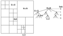
일반적으로, 부호화(또는, 복호화) 장치는 입력 영상(프레임)에 대하여 부호화(또는 복호화)를 수행한다. 부호화는 부호화 유닛 단위별로 이루어질 수 있으며, HEVC에서 부호화 유닛 단위는 CTU(Coding Tree Unit)일 수 있고, CTU는, 도 1에 도시된 바와 같이, 64×64에서 8×8까지 쿼드트리 구조로 분할되고 계층적으로 구성되는 코딩 유닛(Coding Unit; 이하 CU)을 포함한다. 결과적으로 CU는 64×64, 32×32, 16×16, 8×8의 크기를 가질 수 있으며, 특정 크기의 CU보다 큰 크기의 CU를 상위 블록, 작은 크기의 CU를 하위 블록이라 명명할 수 있다. 상위 블록은 재귀적으로 하위 블록으로 분할될 수 있다. Generally, an encoding (or decoding) apparatus performs encoding (or decoding) on an input image (frame). The coding may be performed in units of coding units. In HEVC, the unit of coding unit may be CTU (Coding Tree Unit), and the CTU may be divided into a quad tree structure from 64x64 to 8x8 as shown in FIG. And a coding unit (CU) that is hierarchically configured. As a result, CUs can have sizes of 64 × 64, 32 × 32, 16 × 16, and 8 × 8, and a CU having a size larger than a CU having a specific size can be called a parent block and a CU having a smaller size can be called a sub- have. The upper block can be recursively divided into lower blocks.
CTU의 각 계층은 깊이(depth 또는 level) 정보를 가질 수 있다. 깊이는 CU의 분할된 횟수/및 또는 정도를 나타내므로, CU의 크기에 관한 정보를 포함할 수도 있다. 구체적으로, CU의 크기가 클수록 깊이 값이 작고, CU의 크기가 작을수록 깊이 값이 클 수 있다. HEVC에서는 도 1에 도시된 바와 같이, 깊이 4의 CTU를 지원하며 가장 큰 크기의 CU는 최대 225개의 블록으로 분할될 수 있다. Each layer of the CTU may have depth or level information. The depth represents the number and / or degree of division of the CU, and therefore may include information on the size of the CU. Specifically, the larger the size of the CU, the smaller the depth value, and the smaller the size of the CU, the greater the depth value. In HEVC, as shown in FIG. 1, a CTU of depth 4 is supported, and the largest CU can be divided into a maximum of 225 blocks.
부호화 수행 시, 부호화 장치는 먼저 양자화 파라미터(Quantizer parameter; 이하 Qp)에 따라 CU의 최대 크기 및 최소 크기를 결정한다. 최대 및 최소 크기가 결정되면, CTU가 적용되며, 분할 깊이가 결정된다. 분할 깊이는 블록의 최대 크기에 대응하는 깊이로부터 최소 크기에 대응하는 크기까지의 범위를 의미할 수 있다. 이때 깊이 0에서의 가장 큰 크기의 CU는 LCU(Largest Coding Unit)으로 명명될 수 있다. When encoding is performed, the encoding device first determines the maximum size and the minimum size of the CU according to a quantization parameter (Qp). Once the maximum and minimum sizes are determined, the CTU is applied and the division depth is determined. The division depth may mean a range from the depth corresponding to the maximum size of the block to the size corresponding to the minimum size. At this time, the largest CU at the depth 0 can be named LCU (Largest Coding Unit).
부호화 과정에서 수행되는 예측 및 변환은 예측 블록(Prediction Unit; 이하 PU) 및 변환 블록(Transform Unit; 이하 TU) 단위로 이루어질 수 있으며, CU와 PU 및 TU 간의 관계는 도 2에 도시된 바와 같다. 도 2에서는 CTU가 32×32 크기일 때의 예를 도시하고 있다. 이 경우, 가능한 분할 블록의 크기는 32×32,16×16, 8×8이다.Prediction and transformation performed in the encoding process can be performed in units of a prediction unit (PU) and a transform unit (TU), and the relationship between CU, PU, and TU is as shown in FIG. FIG. 2 shows an example when the CTU is 32 × 32. In this case, the sizes of the possible divided blocks are 32x32, 16x16, and 8x8.
도 2에 도시된 바와 같이, CU가 2N×2N일 때, PU는 2N×2N SKIP, 2N×2N Inter, 2N×N Inter, N×2N Inter, 2N×2N Intra, N×N Intra 중 하나로 선택될 수 있다. 다양한 실시 예에서, PU는 상술한 직사각형 이외에 2N×nU, 2N×nD, nL×2N, nR×2N 모드 중 하나로 선택될 수도 있다. 부호화 장치는 선택된 PU 모드(예측 모드 또는 부호화 모드)에 따라 예측 동작을 수행한다. As shown in Fig. 2, when CU is
TU는 예측 동작을 수행하는 과정에서 생성되는 잔차 신호를 변환하기 위한 변환 동작의 단위로, 도 2에 도시된 바와 같이 PU의 형태와 무관하게 결정된다. 그에 따라, TU의 변환은 PU의 경계를 넘는 잔차 신호에 대해서도 수행될 수 있다. 도 2의 실시 예에서, TU는 쿼드트리를 따라 분할되며 32×32에서부터 4×4까지 변환된다.The TU is a unit of a conversion operation for converting a residual signal generated in the process of performing a prediction operation, and is determined regardless of the type of the PU as shown in FIG. Accordingly, the conversion of the TU can also be performed on the residual signal beyond the boundary of the PU. In the embodiment of FIG. 2, the TU is divided along the quad tree and transformed from 32x32 to 4x4.
종래 기술에서 PU(또는, 예측 모드)를 선택함에 있어서, 부호화 장치는 CU를 분할 깊이에 따라 최대 크기로부터 최소 크기에 도달할 때까지 재귀적으로 분할하면서 율-왜곡 비용을 계산하고, 율-왜곡 비용이 최소가 되는 예측 모드를 선택한다. 구체적으로, 도 2에서 부호화 장치는 32×32 블록에 대한 각 예측 모드 별 율-왜곡 비용을 계산한 후, 이를 하위 블록(16×16)으로 분할하여 4개의 하위 블록에 대한 각 예측 모드 별 율-왜곡 비용을 계산한다. 율-왜곡 비용 계산 및 블록 분할 과정을 반복하여 가장 작은 크기(8×8)의 블록까지 율-왜곡 비용 계산이 완료되면, 부호화 장치는 계산된 율-왜곡 비용들을 비교하여 율-왜곡 비용이 최소가 되는 블록을 PU로 결정하고, 결정된 PU 모드로 예측을 수행한다. In selecting the PU (or the prediction mode) in the prior art, the encoder calculates the rate-distortion cost by recursively dividing the CU from the maximum size to the minimum size according to the division depth, and calculates the rate- The prediction mode in which the cost is minimized is selected. Specifically, in FIG. 2, the encoding apparatus calculates a rate-distortion cost for each prediction mode for a 32 × 32 block, divides the cost-distortion cost into sub-blocks (16 × 16) - Calculate the distortion cost. When the rate-distortion cost calculation to the smallest (8 × 8) block is completed by repeating the rate-distortion cost calculation and the block division process, the encoding device compares the calculated rate-distortion costs to find the rate- Is determined as a PU, and prediction is performed in the determined PU mode.
이러한 종래의 방식은, 부호화 효율을 향상시킬 수 있지만, 최대 크기 블록부터 최소 크기 블록까지 모든 블록의 율-왜곡 비용을 연산해야 하므로, 부호화기의 연산 복잡도가 증가한다는 단점을 갖는다. 그에 따라, 최근에는 고속으로 최적의 예측 모드를 결정할 수 있는 고속 모드 결정 방법이 개발되고 있다. 고속 모드 결정 방법에서는 CU를 분할하며 율-왜곡 비용을 계산하는 동안에 하위 블록으로의 분할 및 율-왜곡 비용 계산을 중지시킬 수 있는 고속 알고리즘을 제공한다. This conventional scheme has the disadvantage of increasing the computational complexity of the encoder since it is necessary to calculate the rate-distortion cost of all blocks from the maximum size block to the minimum size block although the coding efficiency can be improved. Accordingly, in recent years, a fast mode determination method capable of determining an optimum prediction mode at high speed has been developed. The fast mode decision method provides a fast algorithm that can split the CU and halve the division into sub-blocks and the rate-distortion cost calculation while calculating the rate-distortion cost.
일 예로, ECU(Early Coding Unit)에 의하여 결정되는 조기 CU 결정 알고리즘은, 현재 크기의 CU에서 SKIP 모드가 최적의 예측 모드로 결정된 경우, CU를 하위 블록으로 분할하여 다음 깊이의 율-왜곡 비용을 계산하지 않고, 현재 크기의 CU에서 예측 모드 결정을 종료한다. 예를 들어, 64×64 크기의 CU 내에서 64×64 PU의 SKIP 모드 율-왜곡 비용이 64×32 PU 및 32×64 PU에서 계산한 율-왜곡 비용보다 작은 경우, 예측 모드 결정은 64×64 PU 깊이에서 종료되며, 더 작은 크기의 PU에 대한 율-왜곡 비용 계산을 수행할 필요가 없게 된다. 그러나 ECU 기반 조기 알고리즘은 균일하지 않은 질감 또는 복잡한 움직임을 갖는 영상의 부호화에는 적합하지 않은 문제점을 갖는다. For example, the early CU decision algorithm determined by the ECU (Early Coding Unit) divides the CU into sub-blocks to determine the rate-distortion cost of the next depth when the SKIP mode is determined as the optimal prediction mode in the current- The prediction mode decision is terminated in the CU of the current size without calculation. For example, if the SKIP mode rate-distortion cost of 64 × 64 PUs in a 64 × 64 CU is less than the rate-distortion cost calculated at 64 × 32 PU and 32 × 64 PU, then the prediction mode decision is 64 × It ends at 64 PU depth and there is no need to perform a rate-distortion cost calculation for a smaller PU. However, the ECU-based early algorithm has a problem that it is not suitable for encoding an image having an uneven texture or a complex motion.
이를 해결하고자 최근에는 흥미도 기반 바이패스 코딩 방법에 제시되었으나, 앞서 설명한 바와 같이 바이패스 코딩 방법도 구현이 복잡하고 병렬 처리에 적합하지 않은 문제점을 갖는다. In order to solve this problem, the interest-based bypass coding method has been proposed recently. However, as described above, the bypass coding method has a complicated implementation and is not suitable for parallel processing.
따라서, 본 발명에서는 Qp를 이용하여 구현이 간단하고 병렬 처리가 용이한, 예측 모드를 조기에 결정하는 방법을 제공한다. 이하에서는, 본 발명에 따른 예측 모드 결정 방법에 따라 예측을 수행하는 부호화/복호화 방법 및 그 장치에 대하여 구체적으로 설명한다. Accordingly, the present invention provides a method for early determination of a prediction mode, which is easy to implement and facilitates parallel processing using Qp. Hereinafter, a coding / decoding method and apparatus for performing prediction according to the prediction mode determining method according to the present invention will be described in detail.
도 3은 본 발명에 따른 영상 부호화 장치의 구조를 나타낸 블록도이다.3 is a block diagram illustrating the structure of an image encoding apparatus according to the present invention.
도 3을 참조하면, 본 발명에 따른 영상 부호화 장치(100)는 양자화 파라미터 결정부(110), 예측부(120), 변환부(130), 양자화부(140), 엔트로피 부호화부(150), 역양자화부(160), 역변환부(170) 및 필터부(180)를 포함하여 구성될 수 있다.3, an
양자화 파라미터 결정부(110)는 현재 CU에 대한 양자화 파라미터(Quantizer parameter; 이하 Qp)를 결정한다. Qp는 임의의 블록을 직교 변환한 결과 생성된 계수들을 양자화할 때 사용되는 파라미터이다. 양자화 파라미터 결정부(110)는 기설정된 Qp 결정 알고리즘을 이용하여 CU에 대한 기본 Qp를 결정할 수 있다. 일 예로, 양자화 파라미터 결정부(110)는 PU 또는 TU의 크기에 대응하여 Qp를 결정할 수 있다. 구체적으로, 양자화 파라미터 결정부(110)는 기본 Qp 값을 결정하고, PU 또는 TU의 크기가 작아짐에 따라 Qp 값을 지수적으로 증가시킬 수 있다. 이러한 알고리즘은 Qp를 결정하는 방법의 일 예에 불과하며, 본 발명에서는 Qp의 결정 방법에 특별한 제한을 두지 않는다. The quantization
예측부(120)는 예측 모드를 결정하고, 예측 모드에 따라 PU에 대한 예측 블록을 생성한다. 예측 모드를 결정한다는 것은 최적의 PU(최적의 PU 크기)를 선택하고, 해당 크기에 대응하는 예측 모드를 선택한다는 것과 동일한 의미일 수 있다. The
예측부(120)는 현재 PU의 최적 예측 방법이 인터 예측인지 인트라 예측인지를 결정하고, 각 예측 방법의 구체적인 모드를 정할 수 있다. 인터 예측에서는 스킵(skip) 모드, 머지(merge) 모드, MVP(Motion Vector Prediction)가 이용될 수 있으며, 인트라 예측에서는 33개의 방향성 예측 모드와 적어도 2개 이상의 비방향성 모드가 이용될 수 있다. 비방향성 모드는 DC 예측 모드 및 플래너 모드(Planar 모드)를 포함할 수 있다. 예측부(120)는 각각의 모드에 따른 예측을 수행하기 위하여, 인터 예측부 및 인트라 예측부를 포함하여 구성될 수 있다.The
인터 예측부는 이미 부호화 과정을 거치고 복원된 이전 프레임(참조 영상)에서 움직임 추정을 통해 움직임 벡터를 생성하고, 움직임 벡터를 이용한 움직임 보상 과정을 통해, 현재 PU와의 잔차(residual) 신호가 최소화되며 움직임 벡터 크기 역시 최소가 되는 예측 블록을 생성한다. 인터 예측부는 움직임 예측부, 움직임 보상부를 포함하여 구성될 수 있다. 인터 예측을 통해 선택된 참조 영상의 인덱스, 움직임 벡터(ex. Motion Vector Predictor), 잔차 신호 등의 정보는 엔트로피 부호화되어 복호화 장치에 전달될 수 있다. 스킵 모드가 적용되는 경우에는 예측 블록이 복원 블록으로 사용될 수 있으므로, 잔차 신호가 생성, 변환, 양자화, 전송되지 않을 수 있다.The inter-prediction unit has already undergone a coding process and generates a motion vector through motion estimation in a reconstructed previous frame (reference image), and a residual signal with a current PU is minimized through a motion compensation process using a motion vector. And generates a prediction block whose size is also minimized. The inter prediction unit may include a motion prediction unit and a motion compensation unit. Information such as an index of a reference image selected through inter prediction, a motion vector (e.g., a motion vector predictor), and a residual signal may be entropy-encoded and transmitted to a decoding apparatus. When the skip mode is applied, the prediction block may be used as a reconstruction block, so that the residual signal may not be generated, transformed, quantized, or transmitted.
인트라 예측부는 이미 부호화 과정을 거치고 복원된 주변 CU 정보를 이용하여 예측 모드를 결정하고, 결정된 예측 모드를 이용하여 예측 블록을 생성한다. 인트라 예측을 통해 선택된 인트라 예측 모드에 관한 정보는 엔트로피 부호화되어 복호화 장치에 전달될 수 있다.The intra predictor determines a prediction mode using the reconstructed neighboring CU information through a coding process, and generates a prediction block using the determined prediction mode. The information on the intra prediction mode selected through the intra prediction can be entropy encoded and transmitted to the decoding apparatus.
본 발명의 다양한 실시 예에서, 예측부(120)는 Qp에 따라 예측 모드를 결정할 수 있다. 예측부(120)는 Qp값에 따라서 예측 모드의 후보를 결정하고, 예측 모드 후보 중에서 최적의 예측 모드를 결정할 수 있다. In various embodiments of the present invention, the
구체적으로, Qp가 제1 임계값보다 크면, 예측부(120)는 현재 CU에 스킵 모드 또는 머지 모드가 적용되는지를 판단할 수 있다. 현재 CU에 스킵 모드 또는 머지 모드가 적용되면, 예측부(120)는 스킵 모드 또는 머지 모드에 따른 예측을 수행하여 예측 블록을 생성할 수 있다. 스킵 모드 및 머지 모드가 적용되지 않으면, 예측부(120)는 현재 CU에 대하여 2N×2N 인터 모드, 인트라 모드를 예측 모드의 후보로 결정하고, 이들 중에서 율-왜곡 비용이 최소가 되는 예측 모드를 최적의 예측 모드로 결정할 수 있다. 다양한 실시 예에서 제1 임계값은 30일 수 있다. Specifically, if Qp is greater than the first threshold value, the predicting
Qp가 제1 임계값보다 작거나 같고 제2 임계값보다 크면, 예측부(120)는 현재 CU에 스킵 모드 또는 머지 모드가 적용되는지를 판단할 수 있다. 현재 CU에 스킵 모드 또는 머지 모드가 적용되면, 예측부(120)는 머지 모드 수행 후 2N×2N 인터 모드, 인트라 모드를 예측 모드의 후보로 결정하고, 이들 중에서 율-왜곡 비용이 최소가 되는 예측 모드를 최적의 예측 모드로 결정할 수 있다. 현재 CU에 스킵 모드 및 머지 모드가 적용되지 않으면, 예측부(120)는 2N×2N 인터 모드, N×2N 인터 모드, 2N×N 인터 모드, 인트라 모드를 예측 모드의 후보로 결정하고, 이들 중에서 율-왜곡 비용이 최소가 되는 예측 모드를 최적의 예측 모드로 결정할 수 있다. 다양한 실시 예에서 제2 임계값은 25일 수 있다. If Qp is less than or equal to the first threshold and greater than the second threshold, the predicting
Qp가 제2 임계값보다 작거나 같으면, 예측부(120)는 현재 CU에 스킵 모드 또는 머지 모드가 적용되는지를 판단할 수 있다. 현재 CU에 스킵 모드 또는 머지 모드가 적용되면, 예측부(120)는 2N×2N 인터 모드, N×2N 인터 모드, 2N×N 인터 모드, 인트라 모드를 예측 모드의 후보로 결정하고, 이들 중에서 율-왜곡 비용이 최소가 되는 예측 모드를 최적의 예측 모드로 결정할 수 있다. 현재 CU에 스킵 모드 및 머지 모드가 적용되지 않으면, 예측부(120)는 2N×2N 인터 모드, N×2N 인터 모드, 2N×N 인터 모드, 인터 AMP 모드, 인트라 모드를 예측 모드의 후보로 결정하고, 이들 중에서 율-왜곡 비용이 최소가 되는 예측 모드를 최적의 예측 모드로 결정할 수 있다. If Qp is less than or equal to the second threshold value, the predicting
예측부(120)는 상기의 실시 예에 따라 결정된 최적의 예측 모드에 따라 예측을 수행하여 예측 블록을 생성할 수 있다. The
생성된 예측 블록과 원본 블록은 감산기(121)로 전달되고, 감산기(121)를 통하여 예측 블록과 원본 블록 사이의 잔차 신호(또는, 잔차 블록, 잔차 값)가 변환부(130)로 전달될 수 있다. 예측부(120)가 스킵 모드로 PU의 예측 블록을 생성한 경우, 잔차 신호는 변환부(130)로 전달되지 않을 수 있다. The generated prediction block and the original block are transferred to the
변환부(130)는 잔차 신호에 대해 변환(transform)을 수행하여 변환 계수(transform coefficient)를 출력할 수 있다. 변환부(130)는 TU 단위로 변환을 수행할 수 있으며, TU의 크기는 해당 CU의 크기보다 같거나 작으며, 해당 PU의 크기와는 무관하다. 변환부(130)는 잔차 신호를 DCT(Discrete Cosine Transform) 및/또는 DST(Discrete Sine Transform)를 이용하여 변환할 수 있다.The
양자화부(140)는 입력된 변환 계수를 양자화 파라미터에 따라 양자화하여 양자화 계수(quantized coefficient)를 출력할 수 있다.The
엔트로피 부호화부(150)는 양자화부(140)에서 생성된 양자화 계수에 대한 엔트로피 부호화를 수행하여 비트 스트림(bit stream)을 출력할 수 있다. 엔트로피 부호화부(150)는 부호화 과정에서 산출된 값들, 예를 들어 블록 타입 정보, 예측 모드 정보, 분할 단위 정보, PU 정보 및 TU 정보, 움직임 벡터 정보, 참조 영상정보, 블록의 보간 정보, 필터링 정보 등 다양한 정보를 부호화할 수 있다. 엔트로피 부호화에는 예를 들어, 지수 골룸(Exponential Golomb), CAVLC(Context-Adaptive Variable Length Coding), CABAC(Context-Adaptive Binary Arithmetic Coding) 등과 같은 부호화 방법이 사용될 수 있다.The
도 3의 영상 부호화 장치(100)는 인터 예측을 수행하므로, 현재 부호화된 영상은 참조 영상으로 사용되기 위해 복호화되어 저장될 필요가 있다. 따라서 양자화된 계수는 역양자화부(160)에서 역양자화되고 역변환부(170)에서 역변환된다. 역양자화 및 역변환된 계수는 복원된 잔차 신호가 되어 가산기(171)를 통해 예측 블록과 합쳐지고 복원 블록(Reconstructed Block)을 생성할 수 있다. Since the
복원 블록은 필터부(180)를 거치고, 필터부(180)는 디블록킹 필터(deblocking filter), SAO(Sample Adaptive Offset), ALF(Adaptive Loop Filter) 중 적어도 하나 이상을 복원 블록 또는 복원 픽처에 적용할 수 있다. 필터부(180)를 거친 복원 블록은 참조 영상 버퍼에 저장될 수 있다.The restoration block passes through the
도 4는 본 발명에 따른 영상 복호화 장치의 구조를 나타낸 블록도이다. 4 is a block diagram illustrating a structure of an image decoding apparatus according to the present invention.
도 4를 참조하면, 본 발명에 따른 영상 복호화 장치(200)는 엔트로피 복호화부(210), 역양자화부(220), 역변환부(230), 예측부(240) 및 필터부(250)를 포함하여 구성될 수 있다. 4, an
영상 복호화 장치(200)는 영상 부호화 장치(100)에서 출력된 비트 스트림을 입력받아 인트라 모드 또는 인터 모드로 복호화를 수행하고 재구성된 영상, 즉 복원 영상을 출력할 수 있다. 영상 복호화 장치(200)는 입력받은 비트 스트림으로부터 복원된 잔차 블록(reconstructed residual block)을 얻고 예측 블록을 생성한 후 복원된 잔차 블록과 예측 블록을 더하여 재구성된 블록, 즉 복원 블록을 생성할 수 있다.The
엔트로피 복호화부(210)는, 입력된 비트 스트림을 확률 분포에 따라 엔트로피 복호화하여, 양자화된 계수(quantized coefficient) 형태의 심볼을 포함한 심볼들을 생성할 수 있다. 엔트로피 복호화 방법은 상술한 엔트로피 부호화 방법과 유사하다.The
양자화된 계수는 역양자화부(220)에서 양자화 파라미터를 이용해서 역양자화되고 역변환부(230)에서 역변환되며, 양자화된 계수가 역양자화/역변환된 결과, 복원된 잔차 블록이 생성될 수 있다.The quantized coefficients are inversely quantized using the quantization parameters in the
예측부(240)는 인트라 모드 또는 인터 모드에 따라 예측을 수행하여 예측 블록을 생성한다. 본 발명의 다양한 실시 예에서, 예측부(240)는 Qp에 따라 예측 모드를 결정할 수 있으며, 이에 대한 자세한 내용은 상술한 바와 같다. 이를 위하여 예측부(240)는 영상 부호화 장치(100)에서와 유사한 양자화 파라미터 결정부를 포함하거나 별도로 구성되는 양자화 파라미터 결정부(미도시)로부터 양자화 파라미터 값을 수신할 수 있다. The
복원된 잔차 블록과 예측 블록은 가산기(241)를 통해 더해지고, 더해진 블록에는 필터부(250)를 통해 디블록킹 필터, SAO, ALF 중 적어도 하나 이상이 적용될 수 있다. 필터부(250)는 재구성된 영상, 즉 복원 영상을 출력할 수 있다. The reconstructed residual block and the prediction block are added through the adder 241, and at least one of the deblocking filter, SAO, and ALF may be applied to the added block through the
이하에서는, 상기한 영상 부호화 및 복호화 장치의 영상 부호화 및 복호화 방법에 대하여 상세하게 설명한다. 이하에서는 영상 부호화에서 최적의 예측 모드 결정 방법을 위주로 설명하나, 이는 영상 복호화에도 동일하게 적용될 수 있음이 자명하므로 영상 복호화 방법에 대하여는 생략한다. 그러나 이하에서 기술하는 영상 부호화 방법은 그 기술적 사상이 변경되지 않는 범위 내에서 영상 부호화 방법에 대하여 동일한 권리 범위를 갖는다. Hereinafter, a video encoding and decoding method of the image encoding and decoding apparatus will be described in detail. Hereinafter, an optimal prediction mode decision method in the image encoding will be mainly described. However, since it is obvious that the same method can be applied to the image decoding, the image decoding method will be omitted. However, the image coding method described below has the same right range for the image coding method within a range in which the technical idea is not changed.
도 5는 본 발명에 따른 영상 부호화 방법을 나타낸 순서도이다. 5 is a flowchart illustrating an image encoding method according to the present invention.
도 5를 참조하면, 영상 부호화 장치는 현재 CU에 대한 Qp를 판단한다(501). Referring to FIG. 5, the image encoding apparatus determines Qp for the current CU (501).
영상 부호화 장치는 기설정된 알고리즘에 따라 현재 CU에 대한 Qp를 판단할 수 있다. Qp는 현재 CU 의 크기, 해상도 등에 따라 결정될 수 있으며, 그 결정 방법에는 제한을 두지 않는다. The image encoding apparatus can determine the Qp for the current CU according to a predetermined algorithm. Qp can be determined according to the size, resolution, etc. of the current CU, and there is no limitation on the determination method.
다음으로, 영상 부호화 장치는 Qp에 따른 예측 모드의 후보를 결정할 수 있다(502). Qp 가 제1 임계값보다 큰 경우, 영상 부호화 장치는 현재 CU에 스킵 모드 또는 머지 모드가 적용되는지 여부를 판단한 후, 스킵 모드 및 머지 모드가 적용되지 않으면, 2N×2N 인터 모드, 인트라 모드를 예측 모드의 후보로 결정할 수 있다. 다양한 실시 예에서 제1 임계값은 30일 수 있다. Next, the image encoding apparatus can determine a prediction mode candidate according to Qp (502). If Qp is larger than the first threshold value, the image encoding apparatus determines whether a skip mode or merge mode is applied to the current CU. If the skip mode and the merge mode are not applied, the image encoding apparatus predicts a 2N × 2N inter mode and an intra mode Mode candidate. In various embodiments, the first threshold may be thirty.
Qp 가 제1 임계값보다 작고 제2 임계값보다 큰 경우, 영상 부호화 장치는 현재 CU에 스킵 모드 또는 머지 모드가 적용되는지 여부에 따라, 2N×2N 인터 모드, 인트라 모드를 예측 모드의 후보로 결정하거나, 2N×2N 인터 모드, N×2N 인터 모드, 2N×N 인터 모드, 인트라 모드를 예측 모드의 후보로 결정할 수 있다. 다양한 실시 예에서 제2 임계값은 25일 수 있다. If Qp is smaller than the first threshold value and larger than the second threshold value, the image encoding apparatus determines the 2N × 2N inter mode and the intra mode as candidates of the prediction mode, depending on whether a skip mode or merge mode is applied to the current CU Alternatively, the 2N × 2N inter mode, the N × 2N inter mode, the 2N × N inter mode, and the intra mode can be determined as candidates of the prediction mode. In various embodiments, the second threshold may be 25.
Qp 가 제2 임계값보다 작거나 같은 경우, 영상 부호화 장치는 현재 CU에 스킵 모드 또는 머지 모드가 적용되는지 여부에 따라, 2N×2N 인터 모드, N×2N 인터 모드, 2N×N 인터 모드, 인트라 모드를 예측 모드의 후보로 결정하거나, 2N×2N 인터 모드, N×2N 인터 모드, 2N×N 인터 모드, 인터 AMP 모드, 인트라 모드를 예측 모드의 후보로 결정할 수 있다. If Qp is less than or equal to the second threshold value, the image encoding apparatus can perform a 2N × 2N inter mode, an N × 2N inter mode, a 2N × N inter mode, and an intra mode according to whether a skip mode or merge mode is applied to the current CU Mode as candidates for the prediction mode, or the 2N × 2N inter mode, the N × 2N inter mode, the 2N × N inter mode, the inter-AMP mode, and the intra mode as candidates for the prediction mode.
예측 모드 후보의 결정에 있어서, 임계값의 수나 그 값의 설정 및 임계값에 따른 예측 모드의 후보는 본 발명의 기술적 사상이 변하지 않는 범위 내에서 다양한 응용, 변형, 변경이 가능하며, 변경된 실시 예 역시 본 발명의 권리 범위에 속함은 자명하다. In the determination of the prediction mode candidate, the number of threshold values, the setting of the threshold value, and the candidate of the prediction mode depending on the threshold value can be variously applied, modified or changed within the scope of the technical idea of the present invention, It is obvious that the present invention belongs to the scope of the present invention.
다음으로, 영상 부호화 장치는 결정된 예측 모드 후보 중에서 최적의 예측 모드를 선택한다(503). Next, the image encoding apparatus selects an optimal prediction mode from among the determined prediction mode candidates (503).
현재 CU에 스킵 모드 또는 머지 모드가 적용되는 경우, 최적의 예측 모드는 스킵 모드 또는 머지 모드일 수 있다. 다른 경우, 최적의 예측 모드는 각각의 예측 모드 후보에 대하여 계산된 율-왜곡 비용이 최소가 되는 예측 모드가 최적의 예측 모드로 선택될 수 있다. If a skip mode or a merge mode is applied to the current CU, the optimal prediction mode may be a skip mode or a merge mode. In other cases, the optimal prediction mode may be selected as the optimal prediction mode in which the rate-distortion cost calculated for each prediction mode candidate is minimized.
최적의 예측 모드가 결정되면, 영상 부호화 장치는 최적의 예측 모드에 따른 영상 부호화를 수행한다(504). Once the optimal prediction mode is determined, the image encoding apparatus performs image encoding according to the optimal prediction mode (504).
이하에서는, 상술한 본 발명의 실시 예에서, Qp에 따른 예측 모드의 후보를 결정하고, 최적의 예측 모드를 결정하는 방법을 보다 구체적으로 설명한다. Hereinafter, a method of determining candidates of prediction modes according to Qp and determining an optimum prediction mode will be described in more detail in the embodiments of the present invention described above.
도 6은 본 발명에 따른 영상 부호화 방법을 보다 구체적으로 나타낸 순서도이다.6 is a flowchart illustrating a method of encoding an image according to an embodiment of the present invention.
도 6을 참조하면, 영상 부호화 장치는 Qp가 제1 임계값보다 큰지 여부를 판단한다(601). Referring to FIG. 6, the image encoding apparatus determines whether Qp is greater than a first threshold value (Step 601).
Qp가 제1 임계값보다 크면, 영상 부호화 장치는 현재 CU에 스킵 모드가 적용되는지 여부를 판단한다(602). 일 실시 예에서, 영상 부호화 장치는 2N×2N 모드의 움직임 벡터와 CBF(Coded Block Flag)를 이용한 조기 결정 방법(CFM: Cbf Fast mode)을 이용하여 현재 CU 에 스킵 모드가 적용되는지 여부를 판단할 수 있다. 예를 들어, 현재 CU의 움직임 벡터가 0이고 uma와 chroma의 CBF 가 모두 0이면 현재 CU에 스킵 모드가 적용되는 것으로 판단할 수 있다. 그러나 스킵 모드 적용 여부에 대한 판단은 상기한 방법에 한정되지 않으며 다양한 알고리즘에 따라 수행될 수 있다. If Qp is greater than the first threshold, the image encoding apparatus determines whether a skip mode is applied to the current CU (602). In one embodiment, the image encoding apparatus determines whether a skip mode is applied to a current CU by using an early decision method (CFM: Cbf Fast mode) using a 2N × 2N mode motion vector and a CBF (Coded Block Flag) . For example, if the current motion vector of the CU is 0 and the CBF of the uma and chroma are all 0, it can be determined that the skip mode is applied to the current CU. However, the determination as to whether or not the skip mode is applied is not limited to the above-described method and can be performed according to various algorithms.
현재 CU에 스킵 모드가 적용되면, 영상 부호화 장치는 즉시 최적의 예측 모드를 선택(612)하며, 이때 최적의 예측 모드는 스킵 모드로 선택할 수 있다. If a skip mode is applied to the current CU, the image encoding apparatus immediately selects (612) an optimal prediction mode, and the optimal prediction mode can be selected as a skip mode at this time.
현재 CU에 스킵 모드가 적용되지 않으면, 영상 부호화 장치는 현재 CU에 머지 모드가 적용되는지 여부를 판단한다(603). 일 실시 예에서, 영상 부호화 장치는 CBF를 이용하여 현재 CU에 머지 모드가 적용되는지 여부를 판단할 수 있으며, 자세한 내용은 상술한 바와 같다. 그러나 상술한 바와 같이 머지 모드 적용 여부에 대한 판단 방법도 특별한 제한을 두지 않는다. If the skip mode is not applied to the current CU, the image encoding apparatus determines whether the merge mode is applied to the current CU (603). In one embodiment, the image encoding apparatus can determine whether the merge mode is applied to the current CU using the CBF, and the details are as described above. However, the method of determining whether or not the merge mode is applied has no particular limitation as described above.
현재 CU에 머지 모드가 적용되면, 영상 부호화 장치는 머지 모드 예측을 수행하고(604), 최적의 예측 모드를 선택한다(612). 즉, 영상 부호화 장치는 머지 모드만을 예측 모드 후보로 결정하고, 머지 모드를 최적의 예측 모드로 선택할 수 있다. If the merge mode is applied to the current CU, the image encoding apparatus performs merge mode prediction (604) and selects an optimal prediction mode (612). That is, the image encoding apparatus can determine only the merge mode as the prediction mode candidate, and select the merge mode as the optimum prediction mode.
현재 CU에 머지 모드가 적용되지 않으면, 영상 부호화 장치는 2N×2N 인터 모드, 인트라 모드를 예측 모드의 후보로 결정하고, 2N×2N 인터 모드, 인트라 모드에 대한 예측을 수행한다(608). 영상 부호화 장치는 2N×2N 인터 모드, 인트라 모드 예측 결과에 따른 율-왜곡 비용을 비교하여, 이들 중 최적의 예측 모드를 결정할 수 있다(612). If the merge mode is not currently applied to the CU, the image encoding apparatus determines the 2N × 2N inter mode and the intra mode as candidates of the prediction mode, and performs prediction for the 2N × 2N inter mode and intra mode. The image encoding apparatus compares the rate-distortion costs according to the 2N × 2N inter mode and intra mode prediction results, and determines an optimal prediction mode among the 2N × 2N inter mode and the intra mode prediction results (612).
한편, Qp가 제1 임계값보다 크지 않으면, 영상 부호화 장치는 Qp가 제2 임계값보다 큰지 여부를 판단한다(605). On the other hand, if Qp is not greater than the first threshold value, the image encoding apparatus determines whether Qp is greater than a second threshold value (605).
Qp가 제2 임계값보다 크면, 영상 부호화 장치는 현재 CU에 스킵 모드 또는 머지 모드가 적용되는지 여부를 판단한다(606). 스킵 모드 또는 머지 모드가 적용되는지 여부에 대한 판단은 상술한 바와 같다. If Qp is larger than the second threshold value, the image encoding apparatus determines whether a skip mode or merge mode is applied to the current CU (606). The determination as to whether the skip mode or the merge mode is applied is as described above.
현재 CU에 스킵 모드 또는 머지 모드가 적용되면, 영상 부호화 장치는 2N×2N 인터 모드, 인트라 모드를 예측 모드의 후보로 결정한다. 영상 부호화 장치는 머지 모드를 수행하고(607), 2N×2N 인터 모드, 인트라 모드에 대한 예측을 수행한다(608). 영상 부호화 장치는 머지 모드, 2N×2N 인터 모드, 인트라 모드 예측 결과에 따른 율-왜곡 비용을 비교하여, 이들 중 최적의 예측 모드를 결정할 수 있다(612). If a skip mode or merge mode is applied to the current CU, the image encoding apparatus determines the 2N × 2N inter mode and the intra mode as candidates of the prediction mode. The image encoding apparatus performs a merge mode (607), and performs prediction for a 2N × 2N inter mode and an intra mode (608). The image encoding apparatus compares the rate-distortion costs according to the merge mode, the 2N × 2N inter mode, and the intra mode prediction result, and determines the optimal prediction mode among them (612).
현재 CU에 스킵 모드 및 머지 모드가 적용되지 않으면, 영상 부호화 장치는 2N×2N 인터 모드, N×2N 인터 모드, 2N×N 인터 모드, 인트라 모드를 예측 모드의 후보로 결정하고, 2N×2N 인터 모드, 인트라 모드에 대한 예측을 수행한다(610). 영상 부호화 장치는 2N×2N 인터 모드, N×2N 인터 모드, 2N×N 인터 모드, 인트라 모드 예측 결과에 따른 율-왜곡 비용을 비교하여, 이들 중 최적의 예측 모드를 결정할 수 있다(612).If the skip mode and the merge mode are not applied to the current CU, the image encoding apparatus determines 2N × 2N inter mode, N × 2N inter mode, 2N × N inter mode and intra mode as candidates of the prediction mode, Mode, and the intra mode (610). The image encoding apparatus compares the rate-distortion costs according to the 2N × 2N inter mode, the N × 2N inter mode, the 2N × N inter mode, and the intra mode prediction result to determine an optimal prediction mode among them.
한편, Qp가 제2 임계값보다 크지 않으면, 영상 부호화 장치는 현재 CU에 스킵 모드 또는 머지 모드가 적용되는지 여부를 판단한다(609). 스킵 모드 또는 머지 모드가 적용되는지 여부에 대한 판단은 상술한 바와 같다. On the other hand, if Qp is not larger than the second threshold value, the image encoding apparatus determines whether a skip mode or merge mode is applied to the current CU (609). The determination as to whether the skip mode or the merge mode is applied is as described above.
현재 CU에 스킵 모드 또는 머지 모드가 적용되면, 영상 부호화 장치는 2N×2N 인터 모드, N×2N 인터 모드, 2N×N 인터 모드, 인트라 모드를 예측 모드의 후보로 결정하고, 2N×2N 인터 모드, N×2N 인터 모드, 2N×N 인터 모드, 인트라 모드에 대한 예측을 수행한다(610). 영상 부호화 장치는 2N×2N 인터 모드, N×2N 인터 모드, 2N×N 인터 모드, 인트라 모드 예측 결과에 따른 율-왜곡 비용을 비교하여, 이들 중 최적의 예측 모드를 결정할 수 있다(612). If a skip mode or a merge mode is applied to the current CU, the image encoding apparatus determines a candidate for a prediction mode as a 2N × 2N inter mode, an N × 2N inter mode, a 2N × N inter mode and an intra mode, , The N × 2N inter mode, the 2N × N inter mode, and the intra mode (610). The image encoding apparatus compares the rate-distortion costs according to the 2N × 2N inter mode, the N × 2N inter mode, the 2N × N inter mode, and the intra mode prediction result to determine an optimal prediction mode among them.
현재 CU에 스킵 모드 및 머지 모드가 적용되지 않으면, 영상 부호화 장치는 2N×2N 인터 모드, N×2N 인터 모드, 2N×N 인터 모드, 인터 AMP 모드, 인트라 모드를 예측 모드의 후보로 결정하고, 2N×2N 인터 모드, N×2N 인터 모드, 2N×N 인터 모드, 인터 AMP 모드, 인트라 모드에 대한 예측을 수행한다(611). 영상 부호화 장치는 2N×2N 인터 모드, N×2N 인터 모드, 2N×N 인터 모드, 인터 AMP 모드, 인트라 모드 예측 결과에 따른 율-왜곡 비용을 비교하여, 이들 중 최적의 예측 모드를 결정할 수 있다(612).If the skip mode and the merge mode are not applied to the current CU, the image encoding apparatus determines 2N × 2N inter mode, N × 2N inter mode, 2N × N inter mode, inter AMP mode and intra mode as candidates of the prediction mode, Prediction is performed for the 2N × 2N inter mode, the N × 2N inter mode, the 2N × N inter mode, the inter AMP mode, and the intra mode (611). The image encoding apparatus compares the rate-distortion costs according to the 2N × 2N inter mode, the N × 2N inter mode, the 2N × N inter mode, the inter AMP mode, and the intra mode prediction result, (612).
본 발명이 속하는 기술 분야에서 통상의 지식을 가진 자라면 본 발명의 본질적인 특성에서 벗어나지 않는 범위에서 다양한 수정 및 변형이 가능할 것이다. 그리고 본 명세서와 도면에 개시된 실시 예들은 본 발명의 내용을 쉽게 설명하고, 이해를 돕기 위해 특정 예를 제시한 것일 뿐이며, 본 발명의 범위를 한정하고자 하는 것은 아니다. 따라서 본 발명의 범위는 여기에 개시된 실시 예들 이외에도 본 발명의 기술적 사상을 바탕으로 도출되는 모든 변경 또는 변형된 형태가 본 발명의 범위에 포함되는 것으로 해석되어야 한다.It will be understood by those skilled in the art that various changes in form and details may be made therein without departing from the spirit and scope of the invention as defined by the appended claims. It is to be understood that both the foregoing general description and the following detailed description of the present invention are exemplary and explanatory and are intended to provide further explanation of the invention as claimed. Accordingly, the scope of the present invention should be construed as being included in the scope of the present invention, all changes or modifications derived from the technical idea of the present invention.
100: 영상 부호화 장치
110:양자화 파라미터 결정부
120: 예측부
121: 감산기
130: 변환부
140: 양자화부
150: 엔트로피 부호화부
160: 역양자화부
170: 역변환부
171: 가산기
180: 필터부
200: 영상 복호화 장치
210: 엔트로피 복호화부
220: 역양자화부
230: 역변환부
240: 예측부
250: 필터부100: Image coding apparatus 110: Quantization parameter determination unit
120: Prediction unit 121:
130: conversion unit 140: quantization unit
150: an entropy encoding unit 160: an inverse quantization unit
170: Inverse transform unit 171:
180:
200: image decoding apparatus 210: entropy decoding unit
220: Inverse quantization unit 230: Inverse transform unit
240: prediction unit 250: filter unit
Claims (20)
상기 예측 모드의 후보에 대한 율-왜곡 비용을 판단하여, 상기 예측 모드의 후보 중 최적의 예측 모드를 선택하는 단계; 및
상기 최적의 예측 모드에 따라 부호화된 비트 스트림을 출력하는 단계를 포함하는 것을 특징으로 하는 영상 부호화 방법. Determining a prediction mode candidate based on a quantization parameter of a block to be currently coded;
Determining a rate-distortion cost for the candidate of the prediction mode and selecting an optimal prediction mode among the candidates of the prediction mode; And
And outputting an encoded bitstream according to the optimal prediction mode.
상기 양자화 파라미터가 제1 임계값보다 큰 경우, 상기 블록에 스킵 모드가 적용되는지 여부를 판단하는 단계를 포함하고,
상기 최적의 예측 모드를 선택하는 단계는,
상기 블록에 상기 스킵 모드가 적용되면, 상기 스킵 모드를 상기 최적의 예측 모드로 선택하는 단계를 포함하는 것을 특징으로 하는 영상 부호화 방법. 2. The method of claim 1, wherein the step of determining a candidate for the prediction mode comprises:
Determining whether a skip mode is applied to the block if the quantization parameter is greater than a first threshold value,
Wherein the step of selecting the optimal prediction mode comprises:
And selecting the skip mode as the optimal prediction mode if the skip mode is applied to the block.
상기 블록에 상기 스킵 모드가 적용되지 않으면, 상기 블록에 머지 모드가 적용되는지 여부를 판단하는 단계를 포함하고,
상기 최적의 예측 모드를 선택하는 단계는,
상기 블록에 머지 모드가 적용되면, 상기 머지 모드를 상기 최적의 예측 모드로 선택하는 단계를 포함하는 것을 특징으로 하는 영상 부호화 방법. 3. The method of claim 2, wherein the step of determining a candidate for the prediction mode comprises:
Determining whether a merge mode is applied to the block if the skip mode is not applied to the block,
Wherein the step of selecting the optimal prediction mode comprises:
And selecting the merge mode as the optimal prediction mode if the merge mode is applied to the block.
상기 블록에 상기 머지 모드가 적용되지 않으면, 2N×2N 인터 모드, 인트라 모드 중 적어도 하나를 상기 예측 모드의 후보로 결정하는 단계를 포함하고,
상기 최적의 예측 모드를 선택하는 단계는,
상기 2N×2N 인터 모드, 인트라 모드 중 적어도 하나에 대한 율-왜곡 비용을 판단하여, 상기 최적의 예측 모드를 선택하는 단계를 포함하는 것을 특징으로 하는 영상 부호화 방법. 3. The method of claim 2, wherein the step of determining a candidate for the prediction mode comprises:
And determining that at least one of the 2N × 2N inter mode and the intra mode is a candidate for the prediction mode if the merge mode is not applied to the block,
Wherein the step of selecting the optimal prediction mode comprises:
Estimating a rate-distortion cost for at least one of the 2N × 2N inter mode and the intra mode, and selecting the optimal prediction mode.
상기 양자화 파라미터가 상기 제1 임계값보다 크지 않고 제2 임계값보다 큰 경우, 상기 블록에 상기 스킵 모드 또는 머지 모드가 적용되는지 여부를 판단하는 단계;
상기 블록에 상기 스킵 모드 또는 상기 머지 모드가 적용되면, 상기 머지 모드, 2N×2N 인터 모드, 인트라 모드 중 적어도 하나를 상기 예측 모드의 후보로 결정하는 단계; 및
상기 블록에 상기 스킵 모드 및 상기 머지 모드가 적용되지 않으면, 상기 2N×2N 인터 모드, N×2N 인터 모드, 2N×N 인터 모드, 상기 인트라 모드 중 적어도 하나를 상기 예측 모드의 후보로 결정하는 단계를 포함하는 것을 특징으로 하는 영상 부호화 방법. 3. The method of claim 2, wherein the step of determining a candidate for the prediction mode comprises:
Determining whether the skip mode or merge mode is applied to the block if the quantization parameter is not greater than the first threshold value and greater than the second threshold value;
Determining, if the skip mode or the merge mode is applied to the block, at least one of the merge mode, the 2N × 2N inter mode, and the intra mode as a candidate for the prediction mode; And
Determining at least one of the 2N × 2N inter mode, the N × 2N inter mode, the 2N × N inter mode, and the intra mode as candidates for the prediction mode if the skip mode and the merge mode are not applied to the block Wherein the image encoding method comprises:
상기 양자화 파라미터가 상기 제2 임계값보다 크지 않은 경우, 상기 블록에 상기 스킵 모드 또는 상기 머지 모드가 적용되는지 여부를 판단하는 단계;
상기 블록에 상기 스킵 모드 또는 상기 머지 모드가 적용되면, 상기 2N×2N 인터 모드, 상기 N×2N 인터 모드, 상기 2N×N 인터 모드, 상기 인트라 모드 중 적어도 하나를 상기 예측 모드의 후보로 결정하는 단계; 및
상기 블록에 상기 스킵 모드 및 상기 머지 모드가 적용되지 않으면, 상기 2N×2N 인터 모드, 상기 N×2N 인터 모드, 상기 2N×N 인터 모드, 인터 AMP 모드, 상기 인트라 모드 중 적어도 하나를 상기 예측 모드의 후보로 결정하는 단계를 포함하는 것을 특징으로 하는 영상 부호화 방법. 6. The method of claim 5, wherein the step of determining a candidate for the prediction mode comprises:
Determining whether the skip mode or the merge mode is applied to the block if the quantization parameter is not greater than the second threshold;
When the skip mode or the merge mode is applied to the block, at least one of the 2N × 2N inter mode, the N × 2N inter mode, the 2N × N inter mode, and the intra mode is determined as a candidate for the prediction mode step; And
At least one of the 2N × 2N inter mode, the N × 2N inter mode, the 2N × N inter mode, the inter AMP mode, and the intra mode, if the skip mode and the merge mode are not applied to the block, And determining the candidate as a candidate of the candidate image.
상기 예측 모드의 후보에 대한 율-왜곡 비용을 판단하여, 상기 예측 모드의 후보 중 최적의 예측 모드를 선택하는 단계; 및
상기 최적의 예측 모드에 따라 복호화된 영상을 출력하는 단계를 포함하는 것을 특징으로 하는 영상 복호화 방법. Determining a candidate for a prediction mode based on a quantization parameter of a block to be decoded;
Determining a rate-distortion cost for the candidate of the prediction mode and selecting an optimal prediction mode among the candidates of the prediction mode; And
And outputting the decoded image according to the optimal prediction mode.
상기 양자화 파라미터가 제1 임계값보다 큰 경우, 상기 블록에 스킵 모드가 적용되는지 여부를 판단하는 단계를 포함하고,
상기 최적의 예측 모드를 선택하는 단계는,
상기 블록에 상기 스킵 모드가 적용되면, 상기 스킵 모드를 상기 최적의 예측 모드로 선택하는 단계를 포함하는 것을 특징으로 하는 영상 복호화 방법. 8. The method of claim 7, wherein the step of determining a candidate for the prediction mode comprises:
Determining whether a skip mode is applied to the block if the quantization parameter is greater than a first threshold value,
Wherein the step of selecting the optimal prediction mode comprises:
And selecting the skip mode as the optimal prediction mode if the skip mode is applied to the block.
상기 블록에 상기 스킵 모드가 적용되지 않으면, 상기 블록에 머지 모드가 적용되는지 여부를 판단하는 단계를 포함하고,
상기 최적의 예측 모드를 선택하는 단계는,
상기 블록에 머지 모드가 적용되면, 상기 머지 모드를 상기 최적의 예측 모드로 선택하는 단계를 포함하는 것을 특징으로 하는 영상 복호화 방법. 9. The method of claim 8, wherein determining the candidate for the prediction mode comprises:
Determining whether a merge mode is applied to the block if the skip mode is not applied to the block,
Wherein the step of selecting the optimal prediction mode comprises:
And selecting the merge mode as the optimal prediction mode if the merge mode is applied to the block.
상기 블록에 상기 머지 모드가 적용되지 않으면, 2N×2N 인터 모드, 인트라 모드 중 적어도 하나를 상기 예측 모드의 후보로 결정하는 단계를 포함하고,
상기 최적의 예측 모드를 선택하는 단계는,
상기 2N×2N 인터 모드, 인트라 모드 중 적어도 하나에 대한 율-왜곡 비용을 판단하여, 상기 최적의 예측 모드를 선택하는 단계를 포함하는 것을 특징으로 하는 영상 복호화 방법. 9. The method of claim 8, wherein determining the candidate for the prediction mode comprises:
And determining that at least one of the 2N × 2N inter mode and the intra mode is a candidate for the prediction mode if the merge mode is not applied to the block,
Wherein the step of selecting the optimal prediction mode comprises:
Estimating a rate-distortion cost for at least one of the 2N × 2N inter mode and the intra mode, and selecting the optimal prediction mode.
상기 양자화 파라미터가 상기 제1 임계값보다 크지 않고 제2 임계값보다 큰 경우, 상기 블록에 상기 스킵 모드 또는 머지 모드가 적용되는지 여부를 판단하는 단계;
상기 블록에 상기 스킵 모드 또는 상기 머지 모드가 적용되면, 상기 머지 모드, 2N×2N 인터 모드, 인트라 모드 중 적어도 하나를 상기 예측 모드의 후보로 결정하는 단계; 및
상기 블록에 상기 스킵 모드 및 상기 머지 모드가 적용되지 않으면, 상기 2N×2N 인터 모드, N×2N 인터 모드, 2N×N 인터 모드, 상기 인트라 모드 중 적어도 하나를 상기 예측 모드의 후보로 결정하는 단계를 포함하는 것을 특징으로 하는 영상 복호화 방법. 9. The method of claim 8, wherein determining the candidate for the prediction mode comprises:
Determining whether the skip mode or merge mode is applied to the block if the quantization parameter is not greater than the first threshold value and greater than the second threshold value;
Determining, if the skip mode or the merge mode is applied to the block, at least one of the merge mode, the 2N × 2N inter mode, and the intra mode as a candidate for the prediction mode; And
Determining at least one of the 2N × 2N inter mode, the N × 2N inter mode, the 2N × N inter mode, and the intra mode as candidates for the prediction mode if the skip mode and the merge mode are not applied to the block And decoding the decoded image.
상기 양자화 파라미터가 상기 제2 임계값보다 크지 않은 경우, 상기 블록에 상기 스킵 모드 또는 상기 머지 모드가 적용되는지 여부를 판단하는 단계;
상기 블록에 상기 스킵 모드 또는 상기 머지 모드가 적용되면, 상기 2N×2N 인터 모드, 상기 N×2N 인터 모드, 상기 2N×N 인터 모드, 상기 인트라 모드 중 적어도 하나를 상기 예측 모드의 후보로 결정하는 단계; 및
상기 블록에 상기 스킵 모드 및 상기 머지 모드가 적용되지 않으면, 상기 2N×2N 인터 모드, 상기 N×2N 인터 모드, 상기 2N×N 인터 모드, 인터 AMP 모드, 상기 인트라 모드 중 적어도 하나를 상기 예측 모드의 후보로 결정하는 단계를 포함하는 것을 특징으로 하는 영상 복호화 방법. 12. The method of claim 11, wherein the determining of the prediction mode candidate comprises:
Determining whether the skip mode or the merge mode is applied to the block if the quantization parameter is not greater than the second threshold;
When the skip mode or the merge mode is applied to the block, at least one of the 2N × 2N inter mode, the N × 2N inter mode, the 2N × N inter mode, and the intra mode is determined as a candidate for the prediction mode step; And
At least one of the 2N × 2N inter mode, the N × 2N inter mode, the 2N × N inter mode, the inter AMP mode, and the intra mode, if the skip mode and the merge mode are not applied to the block, As a candidate of a candidate for the image.
상기 양자화 파라미터에 기초하여 예측 모드의 후보를 결정하고, 상기 예측 모드의 후보에 대한 율-왜곡 비용을 판단하여, 상기 예측 모드의 후보 중 최적의 예측 모드를 선택하는 예측부;
상기 예측부에서 생성된 잔차 신호를 변환하여 변환 계수를 출력하는 변환부;
상기 변환 계수를 양자화하여 양자화 계수를 출력하는 양자화부; 및
상기 최적의 예측 모드에 따라 생성된 예측 불록 및 상기 양자화 계수를 이용하여 부호화된 비트 스트림을 출력하는 엔트로피 부호화부를 포함하는 것을 특징으로 하는 영상 부호화 장치.A quantization parameter determination unit for determining a quantization parameter of a current block to be encoded;
A prediction unit for determining a prediction mode candidate based on the quantization parameter, determining a rate-distortion cost for the candidate of the prediction mode, and selecting an optimal prediction mode among the candidates of the prediction mode;
A transform unit for transforming the residual signal generated by the predicting unit and outputting a transform coefficient;
A quantization unit for quantizing the transform coefficients and outputting quantization coefficients; And
And an entropy encoding unit for outputting a bitstream encoded using the prediction block generated according to the optimal prediction mode and the quantization coefficient.
상기 양자화 파라미터가 제1 임계값보다 큰 경우, 상기 블록에 스킵 모드가 적용되는지 여부를 판단하고, 상기 블록에 상기 스킵 모드가 적용되면, 상기 스킵 모드를 상기 최적의 예측 모드로 선택하고, 상기 블록에 상기 스킵 모드가 적용되지 않으면, 상기 블록에 머지 모드가 적용되는지 여부를 판단하고, 상기 블록에 머지 모드가 적용되면, 상기 머지 모드를 상기 최적의 예측 모드로 선택하고, 상기 블록에 상기 머지 모드가 적용되지 않으면, 2N×2N 인터 모드, 인트라 모드 중 적어도 하나를 상기 예측 모드의 후보로 결정하고, 상기 2N×2N 인터 모드, 인트라 모드 중 적어도 하나에 대한 율-왜곡 비용을 판단하여, 상기 최적의 예측 모드를 선택하는 것을 특징으로 하는 영상 부호화 장치. 14. The apparatus of claim 13,
Determining whether a skip mode is applied to the block if the quantization parameter is greater than a first threshold value and selecting the skip mode as the optimal prediction mode when the skip mode is applied to the block, If the merge mode is applied to the block, selects the merge mode as the optimal prediction mode, and if the merge mode is applied to the block, Distortion cost for at least one of the 2N × 2N inter mode and the intra mode is determined, and if the ratio of the 2N × 2N inter mode and the intra mode is not more than the optimal And the prediction mode of the image is selected.
상기 양자화 파라미터가 상기 제1 임계값보다 크지 않고 제2 임계값보다 큰 경우, 상기 블록에 상기 스킵 모드 또는 머지 모드가 적용되는지 여부를 판단하고, 상기 블록에 상기 스킵 모드 또는 상기 머지 모드가 적용되면, 상기 머지 모드, 2N×2N 인터 모드, 인트라 모드 중 적어도 하나를 상기 예측 모드의 후보로 결정하고, 상기 블록에 상기 스킵 모드 및 상기 머지 모드가 적용되지 않으면, 상기 2N×2N 인터 모드, N×2N 인터 모드, 2N×N 인터 모드, 상기 인트라 모드 중 적어도 하나를 상기 예측 모드의 후보로 결정하는 것을 특징으로 하는 영상 부호화 장치. 15. The apparatus of claim 14,
Determining whether the skip mode or the merge mode is applied to the block if the quantization parameter is not greater than the first threshold value and greater than the second threshold value and if the skip mode or the merge mode is applied to the block , The merge mode, the 2N × 2N inter mode, and the intra mode as candidates of the prediction mode, and if the skip mode and the merge mode are not applied to the block, the 2N × 2N inter mode, The 2N inter mode, the 2N inter mode, and the intra mode as candidates of the prediction mode.
상기 양자화 파라미터가 상기 제2 임계값보다 크지 않은 경우, 상기 블록에 상기 스킵 모드 또는 상기 머지 모드가 적용되는지 여부를 판단하고, 상기 블록에 상기 스킵 모드 또는 상기 머지 모드가 적용되면, 상기 2N×2N 인터 모드, 상기 N×2N 인터 모드, 상기 2N×N 인터 모드, 상기 인트라 모드 중 적어도 하나를 상기 예측 모드의 후보로 결정하고, 상기 블록에 상기 스킵 모드 및 상기 머지 모드가 적용되지 않으면, 상기 2N×2N 인터 모드, 상기 N×2N 인터 모드, 상기 2N×N 인터 모드, 인터 AMP 모드, 상기 인트라 모드 중 적어도 하나를 상기 예측 모드의 후보로 결정하는 것을 특징으로 하는 영상 부호화 장치. 16. The apparatus of claim 15,
Determining whether the skip mode or the merge mode is applied to the block if the quantization parameter is not greater than the second threshold value and if the skip mode or the merge mode is applied to the block, Inter mode, the Nx2N inter mode, the 2NxN inter mode, and the intra mode as candidates of the prediction mode, and if the skip mode and the merge mode are not applied to the block, Wherein the prediction mode candidate determination unit determines at least one of the N × 2N inter mode, the N × 2N inter mode, the 2N × N inter mode, the inter AMP mode, and the intra mode as candidates for the prediction mode.
상기 양자화 계수를 역양자화하여 변환 계수를 출력하는 역양자화부;
상기 변환 계수를 역변환하여 잔차 신호를 생성하는 역변환부;
상기 블록의 양자화 파라미터에 기초하여 예측 모드의 후보를 결정하고, 상기 예측 모드의 후보에 대한 율-왜곡 비용을 판단하여, 상기 예측 모드의 후보 중 최적의 예측 모드를 선택하는 예측부; 및
상기 예측부에서 생성된 예측 블록 및 상기 잔차 신호를 이용하여 필터링한 영상을 출력하는 필터부를 포함하는 것을 특징으로 하는 영상 복호화 장치. An entropy decoding unit for decoding a block to be decoded and generating a quantized coefficient;
A dequantizer for inversely quantizing the quantized coefficients and outputting transform coefficients;
An inverse transformer for inversely transforming the transform coefficients to generate a residual signal;
A prediction unit for determining a prediction mode candidate based on a quantization parameter of the block, determining a rate-distortion cost for the prediction mode candidate and selecting an optimal prediction mode among the prediction mode candidates; And
And a filter unit for outputting an image filtered using the prediction block and the residual signal generated by the prediction unit.
상기 양자화 파라미터가 제1 임계값보다 큰 경우, 상기 블록에 스킵 모드가 적용되는지 여부를 판단하고, 상기 블록에 상기 스킵 모드가 적용되면, 상기 스킵 모드를 상기 최적의 예측 모드로 선택하고, 상기 블록에 상기 스킵 모드가 적용되지 않으면, 상기 블록에 머지 모드가 적용되는지 여부를 판단하고, 상기 블록에 머지 모드가 적용되면, 상기 머지 모드를 상기 최적의 예측 모드로 선택하고, 상기 블록에 상기 머지 모드가 적용되지 않으면, 2N×2N 인터 모드, 인트라 모드 중 적어도 하나를 상기 예측 모드의 후보로 결정하고, 상기 2N×2N 인터 모드, 인트라 모드 중 적어도 하나에 대한 율-왜곡 비용을 판단하여, 상기 최적의 예측 모드를 선택하는 것을 특징으로 하는 영상 복호화 장치. 18. The apparatus of claim 17,
Determining whether a skip mode is applied to the block if the quantization parameter is greater than a first threshold value and selecting the skip mode as the optimal prediction mode when the skip mode is applied to the block, If the merge mode is applied to the block, selects the merge mode as the optimal prediction mode, and if the merge mode is applied to the block, Distortion cost for at least one of the 2N × 2N inter mode and the intra mode is determined, and if the ratio of the 2N × 2N inter mode and the intra mode is not more than the optimal And a prediction mode of the image decoding apparatus.
상기 양자화 파라미터가 상기 제1 임계값보다 크지 않고 제2 임계값보다 큰 경우, 상기 블록에 상기 스킵 모드 또는 머지 모드가 적용되는지 여부를 판단하고, 상기 블록에 상기 스킵 모드 또는 상기 머지 모드가 적용되면, 상기 머지 모드, 2N×2N 인터 모드, 인트라 모드 중 적어도 하나를 상기 예측 모드의 후보로 결정하고, 상기 블록에 상기 스킵 모드 및 상기 머지 모드가 적용되지 않으면, 상기 2N×2N 인터 모드, N×2N 인터 모드, 2N×N 인터 모드, 상기 인트라 모드 중 적어도 하나를 상기 예측 모드의 후보로 결정하는 것을 특징으로 하는 영상 복호화 장치. 19. The apparatus of claim 18,
Determining whether the skip mode or the merge mode is applied to the block if the quantization parameter is not greater than the first threshold value and greater than the second threshold value and if the skip mode or the merge mode is applied to the block , The merge mode, the 2N × 2N inter mode, and the intra mode as candidates of the prediction mode, and if the skip mode and the merge mode are not applied to the block, the 2N × 2N inter mode, A 2N inter mode, a 2N × N inter mode, and the intra mode as candidates of the prediction mode.
상기 양자화 파라미터가 상기 제2 임계값보다 크지 않은 경우, 상기 블록에 상기 스킵 모드 또는 상기 머지 모드가 적용되는지 여부를 판단하고, 상기 블록에 상기 스킵 모드 또는 상기 머지 모드가 적용되면, 상기 2N×2N 인터 모드, 상기 N×2N 인터 모드, 상기 2N×N 인터 모드, 상기 인트라 모드 중 적어도 하나를 상기 예측 모드의 후보로 결정하고, 상기 블록에 상기 스킵 모드 및 상기 머지 모드가 적용되지 않으면, 상기 2N×2N 인터 모드, 상기 N×2N 인터 모드, 상기 2N×N 인터 모드, 인터 AMP 모드, 상기 인트라 모드 중 적어도 하나를 상기 예측 모드의 후보로 결정하는 것을 특징으로 하는 영상 복호화 장치. 20. The apparatus of claim 19,
Determining whether the skip mode or the merge mode is applied to the block if the quantization parameter is not greater than the second threshold value and if the skip mode or the merge mode is applied to the block, Inter mode, the Nx2N inter mode, the 2NxN inter mode, and the intra mode as candidates of the prediction mode, and if the skip mode and the merge mode are not applied to the block, Wherein the prediction mode candidate determination unit determines at least one of the N × 2N inter mode, the N × 2N inter mode, the 2N × N inter mode, the inter AMP mode, and the intra mode as candidates for the prediction mode.
Priority Applications (2)
| Application Number | Priority Date | Filing Date | Title |
|---|---|---|---|
| KR1020150181056A KR20170072637A (en) | 2015-12-17 | 2015-12-17 | Video Coding/Encoding Method and Apparatus thereof |
| US15/217,734 US20170180738A1 (en) | 2015-12-17 | 2016-07-22 | Video encoding/decoding method and apparatus |
Applications Claiming Priority (1)
| Application Number | Priority Date | Filing Date | Title |
|---|---|---|---|
| KR1020150181056A KR20170072637A (en) | 2015-12-17 | 2015-12-17 | Video Coding/Encoding Method and Apparatus thereof |
Publications (1)
| Publication Number | Publication Date |
|---|---|
| KR20170072637A true KR20170072637A (en) | 2017-06-27 |
Family
ID=59066837
Family Applications (1)
| Application Number | Title | Priority Date | Filing Date |
|---|---|---|---|
| KR1020150181056A KR20170072637A (en) | 2015-12-17 | 2015-12-17 | Video Coding/Encoding Method and Apparatus thereof |
Country Status (2)
| Country | Link |
|---|---|
| US (1) | US20170180738A1 (en) |
| KR (1) | KR20170072637A (en) |
Families Citing this family (9)
| Publication number | Priority date | Publication date | Assignee | Title |
|---|---|---|---|---|
| PL3907999T3 (en) | 2010-09-02 | 2024-04-08 | Lg Electronics, Inc. | Inter prediction |
| CN106162184B (en) * | 2016-07-28 | 2020-01-10 | 华为技术有限公司 | Data block coding method and device |
| US11849132B2 (en) | 2018-09-11 | 2023-12-19 | B1 Institute Of Image Technology, Inc. | Image encoding/decoding method and apparatus using inter prediction |
| CA3131031A1 (en) | 2019-03-21 | 2020-09-24 | Beijing Bytedance Network Technology Co., Ltd. | Improved weighting processing of combined intra-inter prediction |
| CN110446052B (en) * | 2019-09-03 | 2021-02-12 | 南华大学 | 3D-HEVC intra-frame depth map rapid CU depth selection method |
| CN111277838B (en) * | 2020-02-17 | 2022-10-14 | 腾讯科技(深圳)有限公司 | Encoding mode selection method, device, electronic equipment and computer readable medium |
| CN111918058B (en) * | 2020-07-02 | 2022-10-28 | 北京大学深圳研究生院 | Hardware-friendly intra prediction mode fast determination method, device and storage medium |
| CN111885378B (en) * | 2020-07-27 | 2021-04-30 | 腾讯科技(深圳)有限公司 | Multimedia data encoding method, apparatus, device and medium |
| CN113891074B (en) * | 2021-11-18 | 2023-08-01 | 北京达佳互联信息技术有限公司 | Video encoding method and apparatus, electronic apparatus, and computer-readable storage medium |
-
2015
- 2015-12-17 KR KR1020150181056A patent/KR20170072637A/en unknown
-
2016
- 2016-07-22 US US15/217,734 patent/US20170180738A1/en not_active Abandoned
Also Published As
| Publication number | Publication date |
|---|---|
| US20170180738A1 (en) | 2017-06-22 |
Similar Documents
| Publication | Publication Date | Title |
|---|---|---|
| AU2018311926B2 (en) | Systems and methods for partitioning video blocks in an inter prediction slice of video data | |
| JP7094290B2 (en) | Systems and methods for scaling conversion factor level values | |
| JP7382951B2 (en) | System and method for applying deblocking filters to recovered video data | |
| EP2727353B1 (en) | Video coding using adaptive motion vector resolution | |
| KR20170072637A (en) | Video Coding/Encoding Method and Apparatus thereof | |
| WO2018066241A1 (en) | Systems and methods for applying deblocking filters to reconstructed video data | |
| CN111919446B (en) | Method for decoding current video block in video picture | |
| KR102323427B1 (en) | Method and Apparatus for image encoding | |
| WO2019189279A1 (en) | Systems and methods for partitioning video blocks at a boundary of a picture for video coding | |
| JP2017513326A (en) | Deblock filtering using pixel distance | |
| AU2012310514A1 (en) | Method for inducing a merge candidate block and device using same | |
| US10979709B2 (en) | Image encoding method/device, image decoding method/device and recording medium having bitstream stored therein | |
| WO2021049126A1 (en) | Systems and methods for reducing a reconstruction error in video coding based on a cross-component correlation | |
| WO2020129950A1 (en) | Systems and methods for performing inter prediction in video coding | |
| US20220345703A1 (en) | Image encoding method/device, image decoding method/device and recording medium having bitstream stored therein | |
| WO2021070427A1 (en) | Systems and methods for reducing a reconstruction error in video coding based on a cross-component correlation | |
| RU2753643C2 (en) | Systems and methods for performing planar video signal encoding with internal forecasting | |
| KR20180040824A (en) | Video coding method and apparatus using decoder-side intra mode derivation | |
| KR101924959B1 (en) | Method and Apparatus for image encoding | |
| JP6030989B2 (en) | Image encoding method, image decoding method, image encoding device, image decoding device, program thereof, and recording medium recording the program | |
| Milicevic et al. | High Efficiency Video Coding (HEVC) test model HM-16.12 vs. HM-16.6: objective and subjective performance analysis | |
| JP7448549B2 (en) | System and method for deriving quantization parameters for video blocks in video coding | |
| JP5375935B2 (en) | Encoding apparatus and method | |
| KR20150139354A (en) | Method and apparatus of inter-prediction for video encoding/decoding | |
| KR20140079519A (en) | Quantization parameter coding method using average quantization parameter |