KR20170071476A - A tangential flow separator element incorporating flow obstacles, and method of fabrication - Google Patents
A tangential flow separator element incorporating flow obstacles, and method of fabrication Download PDFInfo
- Publication number
- KR20170071476A KR20170071476A KR1020177006919A KR20177006919A KR20170071476A KR 20170071476 A KR20170071476 A KR 20170071476A KR 1020177006919 A KR1020177006919 A KR 1020177006919A KR 20177006919 A KR20177006919 A KR 20177006919A KR 20170071476 A KR20170071476 A KR 20170071476A
- Authority
- KR
- South Korea
- Prior art keywords
- channel
- support
- section
- obstacle
- flow
- Prior art date
Links
- 238000004519 manufacturing process Methods 0.000 title claims description 16
- 239000000463 material Substances 0.000 claims abstract description 47
- 239000012530 fluid Substances 0.000 claims abstract description 45
- 239000000706 filtrate Substances 0.000 claims abstract description 9
- 239000012141 concentrate Substances 0.000 claims abstract description 5
- 239000000843 powder Substances 0.000 claims description 72
- 239000010410 layer Substances 0.000 claims description 61
- 238000000034 method Methods 0.000 claims description 50
- 239000000919 ceramic Substances 0.000 claims description 17
- 238000011144 upstream manufacturing Methods 0.000 claims description 14
- 230000008859 change Effects 0.000 claims description 13
- 239000002243 precursor Substances 0.000 claims description 13
- 239000000203 mixture Substances 0.000 claims description 12
- 238000002844 melting Methods 0.000 claims description 9
- 230000008018 melting Effects 0.000 claims description 9
- 229910010272 inorganic material Inorganic materials 0.000 claims description 8
- 239000011147 inorganic material Substances 0.000 claims description 8
- 239000011324 bead Substances 0.000 claims description 7
- 229920000620 organic polymer Polymers 0.000 claims description 7
- 239000011368 organic material Substances 0.000 claims description 6
- 239000007787 solid Substances 0.000 claims description 6
- 239000011343 solid material Substances 0.000 claims description 6
- 229920005989 resin Polymers 0.000 claims description 5
- 239000011347 resin Substances 0.000 claims description 5
- 238000005507 spraying Methods 0.000 claims description 5
- 239000011344 liquid material Substances 0.000 claims description 4
- 230000003287 optical effect Effects 0.000 claims description 4
- 239000012705 liquid precursor Substances 0.000 claims description 3
- 239000012044 organic layer Substances 0.000 claims description 2
- 239000012528 membrane Substances 0.000 description 26
- 239000011148 porous material Substances 0.000 description 18
- 239000002245 particle Substances 0.000 description 17
- 239000007788 liquid Substances 0.000 description 16
- 239000011230 binding agent Substances 0.000 description 14
- 238000005245 sintering Methods 0.000 description 14
- 239000000725 suspension Substances 0.000 description 12
- 238000009826 distribution Methods 0.000 description 8
- 238000001914 filtration Methods 0.000 description 8
- 238000000926 separation method Methods 0.000 description 8
- 238000001125 extrusion Methods 0.000 description 6
- 238000003475 lamination Methods 0.000 description 6
- 238000001471 micro-filtration Methods 0.000 description 6
- 230000001965 increasing effect Effects 0.000 description 5
- 230000035515 penetration Effects 0.000 description 5
- 238000000108 ultra-filtration Methods 0.000 description 5
- 239000003795 chemical substances by application Substances 0.000 description 4
- 238000005516 engineering process Methods 0.000 description 4
- 239000008187 granular material Substances 0.000 description 4
- 238000001728 nano-filtration Methods 0.000 description 4
- 150000004767 nitrides Chemical class 0.000 description 4
- 238000003921 particle size analysis Methods 0.000 description 4
- 230000035699 permeability Effects 0.000 description 4
- 239000000126 substance Substances 0.000 description 4
- 238000010146 3D printing Methods 0.000 description 3
- 230000003213 activating effect Effects 0.000 description 3
- 238000011960 computer-aided design Methods 0.000 description 3
- 238000010438 heat treatment Methods 0.000 description 3
- 229910052500 inorganic mineral Inorganic materials 0.000 description 3
- 238000005259 measurement Methods 0.000 description 3
- QSHDDOUJBYECFT-UHFFFAOYSA-N mercury Chemical compound [Hg] QSHDDOUJBYECFT-UHFFFAOYSA-N 0.000 description 3
- 229910052753 mercury Inorganic materials 0.000 description 3
- 229910044991 metal oxide Inorganic materials 0.000 description 3
- 150000004706 metal oxides Chemical class 0.000 description 3
- 239000011707 mineral Substances 0.000 description 3
- 230000010287 polarization Effects 0.000 description 3
- 238000000110 selective laser sintering Methods 0.000 description 3
- GWEVSGVZZGPLCZ-UHFFFAOYSA-N Titan oxide Chemical compound O=[Ti]=O GWEVSGVZZGPLCZ-UHFFFAOYSA-N 0.000 description 2
- 239000000654 additive Substances 0.000 description 2
- 230000000996 additive effect Effects 0.000 description 2
- 230000003466 anti-cipated effect Effects 0.000 description 2
- 230000000903 blocking effect Effects 0.000 description 2
- 150000001875 compounds Chemical class 0.000 description 2
- 230000008021 deposition Effects 0.000 description 2
- 238000001035 drying Methods 0.000 description 2
- 238000010894 electron beam technology Methods 0.000 description 2
- 239000007789 gas Substances 0.000 description 2
- 238000007373 indentation Methods 0.000 description 2
- 230000003993 interaction Effects 0.000 description 2
- 238000010030 laminating Methods 0.000 description 2
- 229920002521 macromolecule Polymers 0.000 description 2
- 229910052751 metal Inorganic materials 0.000 description 2
- 239000002184 metal Substances 0.000 description 2
- 150000001247 metal acetylides Chemical class 0.000 description 2
- 230000004048 modification Effects 0.000 description 2
- 238000012986 modification Methods 0.000 description 2
- 230000002093 peripheral effect Effects 0.000 description 2
- 239000012466 permeate Substances 0.000 description 2
- 229920000642 polymer Polymers 0.000 description 2
- 239000002356 single layer Substances 0.000 description 2
- 239000002904 solvent Substances 0.000 description 2
- 239000007921 spray Substances 0.000 description 2
- OGIDPMRJRNCKJF-UHFFFAOYSA-N titanium oxide Inorganic materials [Ti]=O OGIDPMRJRNCKJF-UHFFFAOYSA-N 0.000 description 2
- 238000012546 transfer Methods 0.000 description 2
- 229910018072 Al 2 O 3 Inorganic materials 0.000 description 1
- 229910010413 TiO 2 Inorganic materials 0.000 description 1
- GEIAQOFPUVMAGM-UHFFFAOYSA-N ZrO Inorganic materials [Zr]=O GEIAQOFPUVMAGM-UHFFFAOYSA-N 0.000 description 1
- 238000010521 absorption reaction Methods 0.000 description 1
- 230000009471 action Effects 0.000 description 1
- 239000000853 adhesive Substances 0.000 description 1
- 230000001070 adhesive effect Effects 0.000 description 1
- 229920003180 amino resin Polymers 0.000 description 1
- 238000004458 analytical method Methods 0.000 description 1
- 238000011001 backwashing Methods 0.000 description 1
- 230000004888 barrier function Effects 0.000 description 1
- 230000008901 benefit Effects 0.000 description 1
- 230000005540 biological transmission Effects 0.000 description 1
- 238000012662 bulk polymerization Methods 0.000 description 1
- 229910010293 ceramic material Inorganic materials 0.000 description 1
- 238000004140 cleaning Methods 0.000 description 1
- 239000011247 coating layer Substances 0.000 description 1
- 239000000084 colloidal system Substances 0.000 description 1
- 230000000295 complement effect Effects 0.000 description 1
- 238000009833 condensation Methods 0.000 description 1
- 230000005494 condensation Effects 0.000 description 1
- 238000007596 consolidation process Methods 0.000 description 1
- 230000008878 coupling Effects 0.000 description 1
- 238000010168 coupling process Methods 0.000 description 1
- 238000005859 coupling reaction Methods 0.000 description 1
- 238000005336 cracking Methods 0.000 description 1
- 238000013461 design Methods 0.000 description 1
- 239000003599 detergent Substances 0.000 description 1
- 239000006185 dispersion Substances 0.000 description 1
- 239000003651 drinking water Substances 0.000 description 1
- 235000020188 drinking water Nutrition 0.000 description 1
- 230000000694 effects Effects 0.000 description 1
- 230000005686 electrostatic field Effects 0.000 description 1
- -1 for example Substances 0.000 description 1
- 239000007849 furan resin Substances 0.000 description 1
- 239000007792 gaseous phase Substances 0.000 description 1
- 230000001976 improved effect Effects 0.000 description 1
- 230000001939 inductive effect Effects 0.000 description 1
- 239000010842 industrial wastewater Substances 0.000 description 1
- 230000008595 infiltration Effects 0.000 description 1
- 238000001764 infiltration Methods 0.000 description 1
- 230000000977 initiatory effect Effects 0.000 description 1
- 239000010954 inorganic particle Substances 0.000 description 1
- 238000009434 installation Methods 0.000 description 1
- 230000010354 integration Effects 0.000 description 1
- 230000001788 irregular Effects 0.000 description 1
- 238000005461 lubrication Methods 0.000 description 1
- 238000003754 machining Methods 0.000 description 1
- 230000007246 mechanism Effects 0.000 description 1
- 238000000465 moulding Methods 0.000 description 1
- 239000006259 organic additive Substances 0.000 description 1
- 230000003204 osmotic effect Effects 0.000 description 1
- 230000000737 periodic effect Effects 0.000 description 1
- 239000012071 phase Substances 0.000 description 1
- 239000005011 phenolic resin Substances 0.000 description 1
- 239000004033 plastic Substances 0.000 description 1
- 238000006116 polymerization reaction Methods 0.000 description 1
- 238000003825 pressing Methods 0.000 description 1
- 238000007639 printing Methods 0.000 description 1
- 230000008569 process Effects 0.000 description 1
- 230000001737 promoting effect Effects 0.000 description 1
- 238000005086 pumping Methods 0.000 description 1
- 230000009467 reduction Effects 0.000 description 1
- 230000000717 retained effect Effects 0.000 description 1
- 239000012465 retentate Substances 0.000 description 1
- 238000000518 rheometry Methods 0.000 description 1
- 238000005070 sampling Methods 0.000 description 1
- 238000007493 shaping process Methods 0.000 description 1
- 230000003746 surface roughness Effects 0.000 description 1
- 229920001187 thermosetting polymer Polymers 0.000 description 1
- 238000011282 treatment Methods 0.000 description 1
- 238000007514 turning Methods 0.000 description 1
- XLYOFNOQVPJJNP-UHFFFAOYSA-N water Substances O XLYOFNOQVPJJNP-UHFFFAOYSA-N 0.000 description 1
Images


Classifications
-
- B—PERFORMING OPERATIONS; TRANSPORTING
- B01—PHYSICAL OR CHEMICAL PROCESSES OR APPARATUS IN GENERAL
- B01D—SEPARATION
- B01D46/00—Filters or filtering processes specially modified for separating dispersed particles from gases or vapours
- B01D46/24—Particle separators, e.g. dust precipitators, using rigid hollow filter bodies
-
- B—PERFORMING OPERATIONS; TRANSPORTING
- B01—PHYSICAL OR CHEMICAL PROCESSES OR APPARATUS IN GENERAL
- B01D—SEPARATION
- B01D65/00—Accessories or auxiliary operations, in general, for separation processes or apparatus using semi-permeable membranes
- B01D65/08—Prevention of membrane fouling or of concentration polarisation
-
- B—PERFORMING OPERATIONS; TRANSPORTING
- B01—PHYSICAL OR CHEMICAL PROCESSES OR APPARATUS IN GENERAL
- B01D—SEPARATION
- B01D46/00—Filters or filtering processes specially modified for separating dispersed particles from gases or vapours
- B01D46/24—Particle separators, e.g. dust precipitators, using rigid hollow filter bodies
- B01D46/2403—Particle separators, e.g. dust precipitators, using rigid hollow filter bodies characterised by the physical shape or structure of the filtering element
- B01D46/2418—Honeycomb filters
- B01D46/2451—Honeycomb filters characterized by the geometrical structure, shape, pattern or configuration or parameters related to the geometry of the structure
- B01D46/247—Honeycomb filters characterized by the geometrical structure, shape, pattern or configuration or parameters related to the geometry of the structure of the cells
-
- B—PERFORMING OPERATIONS; TRANSPORTING
- B01—PHYSICAL OR CHEMICAL PROCESSES OR APPARATUS IN GENERAL
- B01D—SEPARATION
- B01D46/00—Filters or filtering processes specially modified for separating dispersed particles from gases or vapours
- B01D46/24—Particle separators, e.g. dust precipitators, using rigid hollow filter bodies
- B01D46/2403—Particle separators, e.g. dust precipitators, using rigid hollow filter bodies characterised by the physical shape or structure of the filtering element
- B01D46/2418—Honeycomb filters
- B01D46/2451—Honeycomb filters characterized by the geometrical structure, shape, pattern or configuration or parameters related to the geometry of the structure
- B01D46/2474—Honeycomb filters characterized by the geometrical structure, shape, pattern or configuration or parameters related to the geometry of the structure of the walls along the length of the honeycomb
-
- B—PERFORMING OPERATIONS; TRANSPORTING
- B01—PHYSICAL OR CHEMICAL PROCESSES OR APPARATUS IN GENERAL
- B01D—SEPARATION
- B01D63/00—Apparatus in general for separation processes using semi-permeable membranes
- B01D63/06—Tubular membrane modules
-
- B—PERFORMING OPERATIONS; TRANSPORTING
- B01—PHYSICAL OR CHEMICAL PROCESSES OR APPARATUS IN GENERAL
- B01D—SEPARATION
- B01D63/00—Apparatus in general for separation processes using semi-permeable membranes
- B01D63/06—Tubular membrane modules
- B01D63/062—Tubular membrane modules with membranes on a surface of a support tube
- B01D63/063—Tubular membrane modules with membranes on a surface of a support tube on the inner surface thereof
-
- B—PERFORMING OPERATIONS; TRANSPORTING
- B01—PHYSICAL OR CHEMICAL PROCESSES OR APPARATUS IN GENERAL
- B01D—SEPARATION
- B01D63/00—Apparatus in general for separation processes using semi-permeable membranes
- B01D63/06—Tubular membrane modules
- B01D63/066—Tubular membrane modules with a porous block having membrane coated passages
-
- B01J35/56—
-
- C—CHEMISTRY; METALLURGY
- C04—CEMENTS; CONCRETE; ARTIFICIAL STONE; CERAMICS; REFRACTORIES
- C04B—LIME, MAGNESIA; SLAG; CEMENTS; COMPOSITIONS THEREOF, e.g. MORTARS, CONCRETE OR LIKE BUILDING MATERIALS; ARTIFICIAL STONE; CERAMICS; REFRACTORIES; TREATMENT OF NATURAL STONE
- C04B35/00—Shaped ceramic products characterised by their composition; Ceramics compositions; Processing powders of inorganic compounds preparatory to the manufacturing of ceramic products
-
- C—CHEMISTRY; METALLURGY
- C04—CEMENTS; CONCRETE; ARTIFICIAL STONE; CERAMICS; REFRACTORIES
- C04B—LIME, MAGNESIA; SLAG; CEMENTS; COMPOSITIONS THEREOF, e.g. MORTARS, CONCRETE OR LIKE BUILDING MATERIALS; ARTIFICIAL STONE; CERAMICS; REFRACTORIES; TREATMENT OF NATURAL STONE
- C04B38/00—Porous mortars, concrete, artificial stone or ceramic ware; Preparation thereof
- C04B38/0006—Honeycomb structures
- C04B38/0009—Honeycomb structures characterised by features relating to the cell walls, e.g. wall thickness or distribution of pores in the walls
-
- B—PERFORMING OPERATIONS; TRANSPORTING
- B01—PHYSICAL OR CHEMICAL PROCESSES OR APPARATUS IN GENERAL
- B01D—SEPARATION
- B01D2321/00—Details relating to membrane cleaning, regeneration, sterilization or to the prevention of fouling
- B01D2321/20—By influencing the flow
- B01D2321/2008—By influencing the flow statically
- B01D2321/2016—Static mixers; Turbulence generators
-
- C—CHEMISTRY; METALLURGY
- C04—CEMENTS; CONCRETE; ARTIFICIAL STONE; CERAMICS; REFRACTORIES
- C04B—LIME, MAGNESIA; SLAG; CEMENTS; COMPOSITIONS THEREOF, e.g. MORTARS, CONCRETE OR LIKE BUILDING MATERIALS; ARTIFICIAL STONE; CERAMICS; REFRACTORIES; TREATMENT OF NATURAL STONE
- C04B2111/00—Mortars, concrete or artificial stone or mixtures to prepare them, characterised by specific function, property or use
- C04B2111/00474—Uses not provided for elsewhere in C04B2111/00
- C04B2111/00793—Uses not provided for elsewhere in C04B2111/00 as filters or diaphragms
Abstract
본 발명은, 처리할 유체 매질을 여과액 및 농축물로 분리하기 위한 모놀리식 접선 유동 세퍼레이터 요소에 관한 것이며, 상기 세퍼레이터 요소는 3차원 구조의 직선형 강체 다공성 서포트(2)를 포함하되 상기 서포트는 서포트의 외측 표면에서 여과액을 회수하기 위해서 처리할 유체 매질의 유동을 통과시키기 위한 적어도 하나의 채널(3)이 내부에 형성된다. 모놀리식 강체 다공성 서포트(2)는 채널(들)의 내측 벽(들) 상에 또는 내에 여과할 유체의 유동에 대한 장애물(9)을 포함하며, 상기 장애물은 서포트와 다공성 텍스처 및 재료의 동질성(identity) 그리고 서포트와 다공성 텍스처 및 재료의 연속성을 갖는다.The present invention relates to a monolithic tangential flow separator element for separating a fluid medium to be treated into a filtrate and a concentrate, said separator element comprising a linear rigid porous support (2) of three-dimensional structure, said support At least one channel (3) is formed therein for passing the flow of the fluid medium to be treated in order to recover the filtrate at the outer surface of the support. The monolithic rigid porous support 2 comprises an obstacle 9 for the flow of the fluid to be filtered on or in the inner wall (s) of the channel (s), said obstacle being the homogeneity of the support and the porous texture and material identity, and continuity of support and porous textures and materials.
Description
본 발명은, 여과액 및 농축물을 생산하도록 처리할 유체 매질의 접선 유동 분리를 위한 요소의 기술분야에 관한 것이며, 일반적으로 요소는 필터 멤브레인이라고 불린다. 더욱 상세하게는, 본 발명은, 막힘(clogging)과 같은 문제들을 감소시키도록, 또는 심지어 제거하도록 작용하는 다중 채널 다공성 서포트에 대한 신규한 형상과, 그러한 서포트를 제조하는 추가적인 제조방법과, 서포트를 포함하는 접선 유동 세퍼레이터 요소에 관한 것이다.The present invention relates to the technical field of elements for tangential flow separation of a fluid medium to be processed to produce filtrate and concentrate, the elements being generally referred to as filter membranes. More particularly, the present invention relates to a novel shape for a multi-channel porous support which serves to reduce or even eliminate problems such as clogging, an additional manufacturing method of manufacturing such a support, To a tangential flow separator element comprising a tangential flow separator element.
멤브레인을 이용하는 분리 방법은, 수많은 분야, 특히 음용수를 생산하기 위한 그리고 공업폐수를 처리하기 위한 환경분야, 화학, 석유화학, 제약, 및 농식품 산업분야, 그리고 생명공학 분야에서 이용된다.Membrane-based separation methods are used in a number of fields, particularly for the production of drinking water and for the treatment of industrial wastewater, in the chemical, petrochemical, pharmaceutical and agri-food industries, and biotechnology.
멤브레인은 선택적인 장벽을 구성하며, 전달력(transfer force)의 작용 하에서, 멤브레인은 처리할 매질의 어떤 성분은 통과시키고 어떤 성분은 통과시키지 않도록 작용한다. 성분은 멤브레인 내의 구멍들의 크기에 대비한 크기의 결과로 통과하거나 통과하지 못하며, 여기서 멤브레인은 필터로서 거동한다. 구멍 크기의 함수로서 그러한 기술들은 "마이크로여과", "울트라여과", 또는 "나노여과"라고 불린다.The membrane constitutes an optional barrier and, under the action of a transfer force, the membrane acts to pass certain components of the medium to be treated and not to pass any components. The component does not pass or pass as a result of the size relative to the size of the pores in the membrane, where the membrane behaves as a filter. Such techniques as a function of hole size are called "microfiltration "," ultrafiltration ", or "nanofiltration ".
상이한 구조 및 텍스처(textures)를 갖는 멤브레인들이 존재한다. 일반적으로, 멤브레인은, 기계적인 강도를 갖는 멤브레인을 제공하는 그리고 형상을 부여하고 그에 따라 멤브레인의 필터 면적을 결정하는 다공성 서포트에 의해 구성된다. 이러한 서포트 상에서, 하나 이상의 분리-수행 층(separation-performing layer)이 적층(deposited)되고, 각각의 층은 수 마이크로미터의 두께를 가지며, "세퍼레이터 층", "필터 층", 또는 "활성 층"이라고도 불린다. 분리시, 여과된 유체는 다공성 서포트의 외측 표면을 향해 가기 위해서 서포트의 다공성 구조를 통하여 확산된다. 분리 층 및 다공성 서포트를 통과하는 처리할 유체의 일부는 "투과액(permeate)" 또는 "여과액(filtrate)"이라고 불리며, 멤브레인을 둘러싸는 수집 챔버에 의해 회수된다. 유체의 나머지 부분은 "농축물(retentate)"이라고 불리며, 대개는, 재순환 루프를 경유하여, 멤브레인으로부터 상류측의 처리할 유체 내로 재주입된다.There are membranes with different structures and textures. Typically, the membrane is constituted by a porous support that provides a membrane with mechanical strength and shapes and thereby determines the filter area of the membrane. In this support, one or more separation-performing layers are deposited, each layer having a thickness of a few micrometers and a "separator layer", "filter layer", or "active layer" . Upon separation, the filtered fluid is diffused through the porous structure of the support to direct toward the outer surface of the porous support. The separation layer and a portion of the fluid to be treated passing through the porous support is called a "permeate" or "filtrate" and is recovered by the collection chamber surrounding the membrane. The remainder of the fluid is referred to as a "retentate" and is usually re-injected from the membrane into the fluid to be treated upstream, via a recycle loop.
종래 방식에 있어서, 서포트는 압출에 의해 소정의 형상으로 최초 제작되고, 그 다음에 요구되는 강도를 보장하기에 충분한 온도 및 시간으로 소결되는 한편, 최종적인 세라믹 내의 개방 및 상호연결된 구멍들의 소정의 텍스처를 보존한다. 이 방법은 얻어진 하나 이상의 직선형 채널을 필수적으로 이끌어내며, 그 후 세퍼레이터 층(들)은 계속해서 적층 및 소결된다. 전통적으로 서포트는, 서포트의 중심축선에 평행하게 배열되는 하나 이상의 직선형 채널을 갖는 형상의 관 형상을 갖는다. 일반적으로, 채널의 내측 표면은 매끄럽고, 어떤 불규칙한 것도 가지지 않는다.In the conventional manner, the supports are initially made into a predetermined shape by extrusion and then sintered at a temperature and for a time sufficient to ensure the required strength, while a predetermined texture of open and interconnected holes in the final ceramic . This method essentially leads to one or more straight channels obtained, after which the separator layer (s) are subsequently laminated and sintered. Traditionally, the support has a tubular shape of a shape with one or more straight channels arranged parallel to the central axis of the support. In general, the inner surface of the channel is smooth and has no irregularities.
그렇지만, 그러한 형상을 갖는 서포트로 제작되는 필터 멤브레인은 막힘의 문제를 겪으며, 결과적으로 유동속도의 측면에서 제한되는 성능을 갖는다. 상세하게는, 작은 입자들 및 거대분자들이 세퍼레이터 층의 표면 상에 흡수될 수 있거나 겔 또는 적층(deposit)의 형태로 그 위에 적층되어 갈 수 있으며, 심지어는 구멍 내로 통과하거나 구멍들 중 일부를 차단시킬 수 있다.However, filter membranes fabricated with supports having such shapes suffer from the problem of clogging and consequently have limited performance in terms of flow velocity. Particularly, small particles and macromolecules can be absorbed on the surface of the separator layer or can be laminated thereon in the form of a gel or deposit, and even pass into holes or block some of the holes .
필터 요소를 이용하는 모든 접선 분리는 선택적인 전달의 원리에 의존하며, 여기서 효율은 멤브레인(활성 층)의 선택성 및 전체로서 고려되는 필터 요소(서포트 + 활성 층)의 투과성(유동)에 의존한다. 선택성 및 투과성은, 활성 층 및 필터 요소의 특성에 의해 결정되지만, 그뿐 아니라, 농도차 편극의 출현, 적층, 및/또는 구멍의 차단에 의해 감소되거나 제한될 수 있다.All tangential separation using a filter element depends on the principle of selective transmission, where the efficiency depends on the selectivity of the membrane (active layer) and the permeability (flow) of the filter element (support + active layer) considered as a whole. The selectivity and permeability are determined by the characteristics of the active layer and the filter element, but may also be reduced or limited by the appearance of the concentration-aided polarization, lamination, and / or blocking of the holes.
농도차 편극 현상은 거대분자들이 처리할 유체 내에 존재할 때 여과 작업이 멤브레인/용액 경계면에 집중되는 동안에 야기되며, 여기서 이것들은 분리력에 대항하여 삼투 배압(osmotic back-pressure)이 가해지도록 하거나, Fick의 법칙의 적용으로 처리할 유체의 중심으로 돌아가 확산되도록 한다. 농도차 편극 현상은 용제의 투과 때문에 멤브레인 부근에서 축적되는 유지 화합물(retained compound)을 초래한다.Concentration differential polarization is caused when the macromolecules are present in the fluid to be treated while the filtration is concentrated at the membrane / solution interface, where they are applied to the osmotic back-pressure against separation forces, The application of the law allows the fluid to diffuse back to the center of the fluid to be treated. Condensation polarization causes a retained compound to accumulate near the membrane due to permeation of the solvent.
적층은, 응축상이 겔 또는 점착성 퇴적물의 형태로 나타나도록 야기시키기에 충분하게 멤브레인 표면에서의 입자들의 농도가 증가할 때 여과 작업 동안에 나타나며, 멤브레인의 저항에 더하여 유압 저항을 상승시킨다.The lamination appears during the filtration operation when the concentration of particles at the membrane surface increases sufficiently to cause the condensed phase to appear in the form of a gel or cohesive deposit, increasing the resistance of the membrane in addition to the resistance of the membrane.
구멍 차단은, 구멍의 크기와 동일하거나 작은 크기의 입자들이 침투할 때 발생하며, 그에 따라 여과 면적에 있어서의 감소를 야기시킨다.The hole blocking occurs when particles of the same or smaller size than the size of the hole penetrate, thereby causing a reduction in the filtration area.
막힘, 그리고 그 가역성이나 비-가역성은, 필터 요소에 의존하는, 특히 세퍼레이터 층, 처리할 액체, 및 작업 파라미터들에 의존하는 복잡한 현상이다.Clogging, and its reversibility or non-reversibility, are complicated phenomena that depend on the filter element, especially on the separator layer, the liquid to be treated, and on the operating parameters.
필터 설비를 설계할 때, 첫째로는 처리될 체적의 측면에서의 요구사항들을 만족시키기 위해서 설치 면적을 증가시킬 것을 야기시키고, 둘째로는 역세(back washing) 또는 세제를 이용하는 주기적인 세척 사이클과 같은, 사후 막힘을 해결하기 위한 특정 기술적인 수단을 이용할 필요가 있기 때문에, 막힘은 여과의 경제적인 매력에 대한 중요한 브레이크이다.When designing a filter installation, it first causes an increase in the footprint to meet the requirements in terms of volume to be treated, and secondly it causes back washing or periodic cleaning cycles using detergents Clogging is an important break for the economical appeal of filtration, since it is necessary to use specific technical measures to solve post-clogging.
종래의 기술에 있어서, 필터 요소의 채널 내츨의 난류 유동 조건을 생성함으로써 막힘 현상을 감소시키는 것이 이미 제안되어 있다.In the prior art, it has already been proposed to reduce the clogging by creating a turbulent flow condition of the channel element of the filter element.
처음으로, 관형 필터 요소 내로 난류-생성 장치를 도입한 것이 제안되어 있다. 특히, D. M. Krstic 등의 Journal of Membrane Science 208 (2002) pp. 303-314에 대해 참조가 이루어질 수 있다. 막힘을 제한함으로써, 이들 장치는 침투 유동을 향상시키고, 계속해서 여과의 효율을 향상시키도록 작용한다. 그럼에도 불구하고, 관형 요소 내에 그러한 장치들을 설치하고 부착시키는 것은 어렵고 복잡한 작업이다. 나아가서, 이것은 장비의 신뢰성을 해치는 고질적인 진동문제를 일으킨다.For the first time, it has been proposed to introduce a turbulence-generating device into a tubular filter element. In particular, D. M. Krstic et al., Journal of Membrane Science 208 (2002) pp. References to 303-314 may be made. By limiting the clogging, these devices serve to improve the infiltration flow and subsequently improve the efficiency of filtration. Nonetheless, installing and attaching such devices within the tubular element is a difficult and complex task. Furthermore, this causes permanent vibration problems that impair the reliability of the equipment.
M. Y. Jaffrin의 Journal of Membrane Science 324 (2008) pp. 7-25에 또 다른 복잡한 시스템이 제안되어 있으며, 이것은 난류를 생성시키기 위해서 서로에 대해 회전하는 중심 모듈 및 원형 멤브레인을 이용한다. 그렇지만 이것은 최종적인 큰 전단속도가 막힘을 감소시키도록 작용하는 것을 보여준다.M. Y. Jaffrin, Journal of Membrane Science 324 (2008) pp. 7-25, another complex system is proposed, which uses a central module and a circular membrane that rotate with respect to each other to create turbulence. However, this shows that the final large shear rate acts to reduce clogging.
또 다른 해결책은 관형 요소의 형상 변형을 포함한다. 프랑스 특허 FR 2 503 615 호에는 압력 하에서 주입된 가스 혼합물을 여과하는 원통형 튜브가 개시되며, 여기서 튜브의 내측 벽은 가스상들 중 하나가 튜브의 벽 상에 축적되는 것을 방지하여 가스 확산에 의해 분리를 향상시키는 난류를 생성하기 위한 오목부(indentation)를 갖는다. 이 오목부는 압출 다이를 떠나는 튜브가 그 벽의 전체 두께에 걸쳐 국부적으로 튜브를 변형시키는 롤러들 또는 도구들 사이를 통과하도록 야기시킴으로써 형성된다. 프랑스 특허 FR 2 503 616 호에는 동일한 원리에 기초한 방법이 개시되며, 이 방법은 튜브의 양측에 서로 마주하도록 또는 교대로 배열되는 널링 휠(knurling wheels)을 적용함으로써 압출 다이를 떠나는 튜브의 벽을 변형시키는 것을 포함한다.Another solution includes shape modification of the tubular element.
이들 2개의 문헌에서, 단일-채널 튜브를 압출하는 이전 단계 이후에, 최종 성형 단계는 튜브의 외측 표면에 대항하여 회전 펀치 등을 가압함으로써 단일 채널의 내측에 오목부를 형성하도록 하는 소성 변형에 의해 수행된다. 그러한 "오목부"를 얻는 것은 재료의 연성, 다시 말해서 파손 없이 영구적인 변형을 이룰 수 있는 것에 대한 적절성에 따라 용이하거나 어려울 수 있다. 그렇지만, 세라믹 멤브레인을 제조하기 위하여 이용되는 화합물은 양호한 연성을 나타내지 못한다: 이것들은 압출에 의해 용이하게 성형되지만, 일반적으로 5% 미만의 파손 신장률(breaking elongation)을 갖는다. 나아가서, 그러한 기술로는, 단지 작은 크기의 오목부만을 얻을 수 있다. 마지막으로, 튜브의 두께에 걸쳐 이루어지는 변형은 재료 내에 응력 수준을 높이고 깨질 우려를 불러일으키며, 그에 따라 기계적인 강도를 크게 떨어뜨린다. 또한, 프랑스 출원 FR 2 736 843호에는, 서포트의 주변 벽이 부드럽지만, 오목부를 포함하는 벽을 갖춘 단일 채널을 가지는 다공성 튜브가 제안된다. 이를 위해, 다공성 튜브는 그 축선을 따라 배열되는 원통형 핀을 포함하는 압출 다이에 의해서 성형되며, 이 핀 또는 압출 다이의 출구는 회전하도록 장착되고 원형이 아닌 단면을 갖는다. 또, 그 제조 기술은 특정 타입의 오목부, 즉 세퍼레이터의 일단으로부터 타단까지 연속적인 오목부로 제한되며, 채널의 유동 단면에 있어서 어떠한 변화도 발생시키지 못한다. 나아가서, 일련의 내부 채널을 가지는 세퍼레이터 요소를 제조하는 것으로 바뀔 수 없다. 그렇지만, 필터 표면 면적을 증가시킬 수 있어 성능을 개선할 수 있기 때문에, 다중 채널 세퍼레이터 요소에 대한 요구가 지속적으로 증가하고 있다.In these two documents, after the previous step of extruding the single-channel tube, the final shaping step is performed by plastic deformation so as to form a recess in the inside of the single channel by pressing the rotating punch or the like against the outer surface of the tube do. Obtaining such "recesses" can be easy or difficult, depending on the ductility of the material, i. E. Suitability for achieving permanent deformation without breakage. However, the compounds used to make ceramic membranes do not exhibit good ductility: they are easily molded by extrusion, but generally have a breaking elongation of less than 5%. Furthermore, with such a technique, only a small-sized concave portion can be obtained. Finally, deformation over the thickness of the tube raises the stress level in the material and raises the risk of cracking, thereby greatly reducing the mechanical strength.
동일한 방식으로, 유럽 특허 EP 0 813 445 호에는 하나 이상의 채널을 갖춘 필터 요소가 개시되어 있으며, 각각의 채널은 단일-, 이중-, 또는 삼중-홈일 수 있는 나선 홈을 포함한다. 이 필터 요소는 프랑스 문헌 FR 2 736 843 호에서 설명된 필터 요소와 같은 단점을 갖는다.In the same way, European Patent EP 0 813 445 discloses a filter element with one or more channels, each channel including a single-, double-, or triple-groove helical groove. This filter element has the same disadvantages as the filter element described in
본 명세서에 있어서, 본 발명은, 신규한 필터 요소 및 그것을 제작하기에 적합한 제조 기술 제공을 제안하며, 여기서 필터 요소는 막힘 현상을 감소시키거나, 심지어 그것을 제거하기에 적합한 단일-채널 또는 다중 채널구조 및 형상을 갖는다. 본 발명의 목적은, 종래 기술의 해결책에서의 단점을 나타내지 않으면서, 높은 표면 전단응력을 생성하여 채널 내측의 난류를 증강시키도록, 필요에 따라 조절될 수 있는 형상의 신규한 필터 요소를 제공하고자 하는 것이다.The present invention proposes to provide a novel filter element and a manufacturing technique suitable for making it, wherein the filter element is a single-channel or multichannel structure suitable for reducing clogging or even removing it And shape. It is an object of the present invention to provide a novel filter element of a shape that can be adjusted as needed so as to create a high surface shear stress and to enhance the turbulence inside the channel without showing the drawbacks of the prior art solution .
그러한 목적을 성취하기 위해서, 본 발명은, 처리할 유체 매질을 여과액 및 농축물로 분리하기 위한 모놀리식 접선 유동 세퍼레이터 요소를 제공하며, 상기 세퍼레이터 요소는 3차원 구조의 직선형 강체 다공성 서포트를 포함하되 상기 서포트는 서포트의 외측 표면으로부터 여과액을 회수하기 위해서 처리할 유체 매질의 유동을 통과시키기 위한 적어도 하나의 채널이 내부에 배열되며, 상기 서포트의 외측 표면은 일정한 프로파일을 갖는다.In order to achieve such a purpose, the present invention provides a monolithic tangential flow separator element for separating a fluid medium to be treated into a filtrate and a concentrate, said separator element comprising a linear rigid porous support of a three-dimensional structure Wherein the support has at least one channel disposed therein for passing a flow of the fluid medium to be treated to recover the filtrate from the outer surface of the support and the outer surface of the support has a constant profile.
본 발명에 따르면, 모놀리식 강체 다공성 서포트는 채널(들)의 내측 벽(들) 상에 또는 내에 여과할 유체의 유동에 대한 장애물을 포함하며, 상기 장애물은 서포트와 다공성 텍스처 및 재료의 동질성(identity) 및 연속성을 가지며, 채널의 길이방향 축선을 따라서 취해지는 제1 위치와 제2 위치 사이에서 나타나는 바와 같이, 상기 장애물은, 그 주변에서 유체가 유동할 수밖에 없도록 하고, 그에 따라 유체의 유동을 저해하거나 방해한다.According to the present invention, the monolithic rigid porous support comprises an obstacle to the flow of fluid to be filtered on or in the inner wall (s) of the channel (s), which obstruct the homogeneity of the support and porous textures and materials identity, and continuity of the obstruction, as shown between the first position and the second position taken along the longitudinal axis of the channel, the obstacle is forced to flow at its periphery, It interferes or interferes.
나아가서, 본 발명의 요소는 또한 다음의 추가적인 특징들 중 적어도 하나의 특징 및/또는 나머지 특징들을 결합하여 가질 수도 있다:Furthermore, elements of the invention may also have at least one of the following additional features and / or the remainder of the features combined:
- 채널의 적어도 하나의 장애물은, 상기 채널 내에서 처리할 유체의 유동방향으로 급작스럽게 좁아지거나 수렴하는 노즐을 생성하는 것; - at least one obstacle of the channel creating a nozzle that quickly collapses or converges in the flow direction of the fluid to be treated within the channel;
- 채널의 적어도 하나의 장애물은, 상기 장애물의 위치에서 국부적으로 좁아지는 유동 횡단면을 생성하며, 상기 유동 횡단면은, 상기 채널의 길이방향 축선에 수직이고, 상기 장애물로부터 상류 및 하류측에 위치된 채널 부분의 형상(들)과는 상이한 형상을 가지는 것; At least one obstacle of the channel creates a flow cross-section that locally narrows at the location of the obstacle, the flow cross-section being perpendicular to the longitudinal axis of the channel, and located upstream and downstream from the obstacle, Having a shape different from the shape (s) of the part;
- 가장 좁은 유동 횡단면과, 채널의 상기 가장 좁은 유동 횡단면으로부터 상류측에 위치된 부분과의 사이에서, 다음 리스트로부터 취해진 기준들 중 하나는 변화하지 않고 유지되는 한편 다른 기준들은 변화하며, 상기 기준은: 채널의 유동 횡단면의 형상, 면적, 윤변, 및 수력직경인 것; Between the narrowest flow cross section and the part located upstream from the narrowest flow cross section of the channel one of the references taken from the following list remains unchanged while the other references change, : The shape, area, circumference, and hydraulic diameter of the flow cross-section of the channel;
- 가장 좁은 유동 횡단면과, 채널의 상기 가장 좁은 유동 횡단면으로부터 상류측에 위치된 부분과의 사이에서, 다음 리스트로부터 취해진 기준들 모두는 변화하지 않고 유지되며, 상기 기준은: 형상, 면적, 윤변, 및 수력직경인 것; - between the narrowest flow cross section and the portion located upstream from the narrowest flow cross section of the channel, all of the references taken from the following list remain unchanged, the criterion being: shape, area, And hydraulic diameter;
- 채널의 적어도 하나의 장애물은, 상기 채널의 길이방향 축선에 수직인 유동 횡단면을 가지며, 상기 유동 횡단면은 채널의 길이방향 축선을 따라서 취해진 2개의 위치 사이에서 상기 채널의 길이방향 축선을 중심으로 회전하는 것; At least one obstacle of the channel has a flow cross-section perpendicular to the longitudinal axis of the channel, the flow cross-section being rotated about the longitudinal axis of the channel between two positions taken along the longitudinal axis of the channel To do;
- 채널의 적어도 하나의 장애물은, 상기 채널의 양단부 사이에서 불연속적인 방식으로 상기 채널의 길이방향 축선을 중심을 회전하는 유동 횡단면을 갖는 것; At least one obstacle of the channel has a flow cross-section that rotates about the longitudinal axis of the channel in a discontinuous manner between both ends of the channel;
- 상기 요소는, 채널의 내측 벽 상에 연속적으로 적층되고 상기 장애물을 완전히 덮는 적어도 하나의 세퍼레이터 층을 포함하는 것; The element comprises at least one separator layer continuously deposited on the inner wall of the channel and completely covering the obstacle;
- 다공성 서포트는 유기질 또는 무기질인 재료로 만들어지는 것; - the porous support is made of an organic or inorganic material;
- 세퍼레이터 층 또는 중간 층은 유기질 또는 무기질인 재료로 만들어지는 것; 그리고 The separator layer or intermediate layer being made of an organic or inorganic material; And
- 다공성 서포트의 3차원 구조는 광학 현미경 또는 주사 전자 현미경에 의해 관찰될 수 있는 상이한 플라이(plies)들을 갖는 것.- the three-dimensional structure of the porous support has different plies that can be observed by an optical microscope or a scanning electron microscope.
본 발명의 접선 유동 세퍼레이터 요소를 제조하는 방법은, 소정의 3차원 형상을 점진적으로 쌓아올리도록 서로 중첩되어 연속적으로 본딩되는 개별적인 플라이들을 형성함으로써 서포트의 3차원 구조를 만드는 단계를 포함한다.A method of manufacturing a tangential flow separator element of the present invention comprises the steps of making a three-dimensional structure of the support by forming individual plies that are successively bonded to one another in a superimposed manner to progressively stack predetermined three-dimensional shapes.
나아가서, 본 발명의 방법은 또한 다음 추가적인 특징들 중 적어도 하나의 특징 및/또는 나머지 특징들을 결합하여 포함할 수도 있다:Further, the method of the present invention may also combine at least one of the following additional features and / or other features:
- 다음 단계들: - Next steps:
- 다공성 서포트를 형성하기 위한 재료의 연속적인 베드를 만드는 단계로서, 상기 베드는 플라이에서의 상기 다공성 서포트의 단면보다 큰 면적에 걸쳐 일정한 두께를 가지는, 단계; 및 Making a continuous bed of material for forming a porous support, said bed having a constant thickness over an area larger than the cross-section of said porous support in the ply; And
- 개별적인 플라이를 생성하도록, 각각의 플라이에 대하여 결정되는 패턴을 형성하기 위하여 재료의 일부를 국부적으로 경화하는 한편, 이러한 방식으로 만들어지는 바와 같은 개별적인 플라이를 앞선 플라이에 대해 동시에 본딩하는 단계; - locally curing a portion of the material to form a pattern determined for each ply, while simultaneously bonding the individual plies as made in this manner to the preceding ply, so as to produce an individual ply;
를 반복함으로써 3차원 구조를 만드는 단계; To form a three-dimensional structure;
- 광중합 가능한 수지와 같은 액체 재료 또는 분말의 형태인 고체 재료의 연속적인 베드를 만드는 단계; Making a continuous bed of solid material in the form of a liquid material or powder such as a photopolymerizable resin;
- 유기질 또는 무기질 분말의 형태인 고체 재료의 연속적인 베드를 만드는 단계; - making a continuous bed of solid material in the form of an organic or inorganic powder;
- 내부에 배치된 무기질 분말을 갖는 광중합 가능한 액체 전구체의 형태인 매질의 연속적인 베드를 만드는 단계; Making a continuous bed of medium in the form of a photopolymerizable liquid precursor having an inorganic powder disposed therein;
- 각각의 플라이는, 유기질 서포트 및 유기질 층을 이루도록 이용되는 열 가용성 유기 폴리머, 또는 무기질 특성의 서포트로, 세라믹 무기질 분말과 열 가용성 유기 폴리머를 만들기 위한 혼합물인 열 가용성(thermofusible) 고체 전구체의 스트링의 연속적인 또는 불연속적인 용융에 의해 만들어지는 것; 그리고 Each ply is a thermally soluble organic polymer used to make an organic support and an organic layer, or a support of an inorganic character, a string of thermofusible solid precursors which is a mixture of a ceramic mineral powder and a thermally soluble organic polymer Made by continuous or discontinuous melting; And
- 레이저 빔 내에서 용융되는 분말을 분무함으로써 재료의 연속적인 비드를 생성하는 단계.- generating a continuous bead of material by spraying the powder to be melted in the laser beam.
본 발명의 내용에서 한정되는 방법에 의해 얻어지는 접선 유동 세퍼레이터 요소는, 서포트의 3차원 구조를 쌓아올리는 것을 이끌어 낸다. 이러한 구조는 광학 현미경 또는 주사 전자 현미경에 의해 다양한 플라이들을 관찰함으로써 드러남을 알 수 있을 것이다. 물론, 다양한 플라이들의 경계는 가능한 한 미약한(tenuous) 것이 바람직하다.The tangential flow separator element obtained by the method defined in the context of the present invention leads to the build up of the three-dimensional structure of the support. This structure can be seen by observing the various plies by an optical microscope or a scanning electron microscope. Of course, it is desirable that the boundaries of the various plies are as tenuous as possible.
첨부된 도면들을 참조하여 이루어진 이어지는 설명으로부터 다른 여러 특징들이 드러날 수 있으며, 첨부 도면들은 비제한적인 예로서 본 발명의 실시형태들을 도시한다.BRIEF DESCRIPTION OF THE DRAWINGS Other features may be apparent from the following description taken in conjunction with the accompanying drawings, which illustrate embodiments of the invention as non-limiting examples.
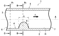
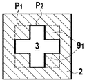
도 1a는, 장애물의 실시형태를 나타내는 서포트의 길이방향 단면도이다.
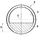
도 1b 및 1c는, 유체의 유동방향에 대하여 장애물로부터 상류에서 그리고 장애물 위치에서 각각 취해진 서포트의 단면도이다.
도 2는, 급작스럽게 좁아지는 노즐 및 수렴하는 노즐 양쪽 모두를 발생시키는 장애물을 나타내는 서포트의 길이방향 단면도이다.
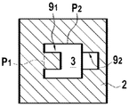
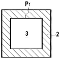
도 3a 및 3b는, 면적변화 없이 채널의 유동단면(flow section)에 있어서의 변화를 나타내는, 장애물로부터 상류에서 그리고 장애물 위치에서 각각 취해진 서포트의 단면도이다.
도 4a 및 4b는, 윤변(wetted perimeter)변화 없이 채널의 유동단면에 있어서의 변화를 나타내는, 장애물로부터 상류에서 그리고 장애물 위치에서 각각 취해진 서포트의 단면도이다.
도 5a 및 5b는, 수력직경(hydraulic diameter)변화 없이 채널의 유동단면에 있어서의 변화를 나타내는, 장애물로부터 상류에서 그리고 장애물 위치에서 각각 취해진 서포트의 단면도이다.
도 6a 및 6b는, 각각, 치수가 변화하는 동안에 채널의 유동단면의 형상의 변함없는 본질을 나타내는, 서포트의 길이방향 단면도 및 횡단면도이다.
도 7a 및 7b는, 각각, 변하지 않는 치수를 갖는 채널의 유동단면의 형상의 변함없는 본질을 나타내는, 서포트의 길이방향 단면도 및 횡단면도이다.
도 8은 국부적으로 변하지 않는 유동단면의 선회부(turning)를 나타내는 서포트의 길이방향으로 일부 절개된 도면이다.1A is a longitudinal sectional view of a support showing an embodiment of an obstacle;
1B and 1C are cross-sectional views of a support taken upstream from an obstacle and at an obstacle location, respectively, with respect to the flow direction of the fluid.
2 is a longitudinal cross-sectional view of a support showing obstacles that generate both suddenly narrowing nozzles and converging nozzles.
3A and 3B are cross-sectional views of a support taken from an obstacle upstream and at an obstacle position, respectively, showing the change in the flow section of the channel without changing the area.
Figs. 4A and 4B are cross-sectional views of a support, taken from an obstacle upstream and at an obstacle location, respectively, showing variations in the flow cross-section of the channel without wetted perimeter changes. Fig.
5A and 5B are cross-sectional views of a support taken upstream from an obstacle and at an obstacle location, respectively, showing variations in the flow cross-section of the channel without hydraulic diameter variations.
Figures 6a and 6b are longitudinal and cross-sectional views, respectively, of the support, showing the constant nature of the shape of the flow cross-section of the channel during the change of dimension.
7A and 7B are a longitudinal sectional view and a cross-sectional view, respectively, of the support, showing the unchanging nature of the shape of the flow cross-section of the channel with unchanging dimensions.
Fig. 8 is a partially cut away view in the longitudinal direction of a support showing turning of a locally unchanged flow section. Fig.
예비적인 측면으로, 본 명세서의 기재내용에서 사용되는 몇몇 용어들에 대한 정의가 주어진다.As a preliminary aspect, definitions of some terms used in the description of this specification are given.
"평균입도크기(mean grain size)"라는 용어는, 체적분포에 대한 d50 값을 의미하기 위해 사용되며, 여기서 알갱이의 전체 체적의 50%가 이 d50 값보다 작은 직경을 가지는 알갱이들의 체적에 상응한다. 체적분포는 알갱이 직경의 함수로서 알갱이 체적 빈도(grain volume frequencies)를 그리는 곡선(해석함수)이다. d50 값은 레이저 회절 입도분석에 의해 얻어지는 것과 같은 빈도 곡선 아래에 위치되는 2개의 동일한 면적 부분들 사이의 중간값에 상응하며, 여기서 레이저 회전 입도분석은 알갱이의 평균직경을 측정하기 위하여 본 명세서에서 사용되는 참조기술이다. d50을 측정하기 위한 기술과 관련하여, 특히 다음과 같은 것을 참조할 수 있다;The term "mean grain size" is used to mean the d50 value for the volume distribution, where 50% of the total volume of the granules corresponds to the volume of granules having diameters smaller than this d50 value . The volume distribution is a curve (analytical function) that draws the grain volume frequencies as a function of the grain diameter. The d50 value corresponds to an intermediate value between two identical area portions located below the frequency curve as obtained by laser diffraction particle size analysis, wherein the laser rotation particle size analysis is used herein to measure the average diameter of the particles . With regard to the technique for measuring d50, it is particularly possible to refer to the following;
- ISO 표준 13320:2009, 레이저 입도분석 기술; - ISO standard 13320: 2009, Laser particle size analysis technology;
- ISO 표준 14488:2007, 분석 기반으로 분말을 샘플링하는 기술; 및 - ISO standard 14488: 2007, a technique for sampling powder based on analysis; And
- ISO 표준 14887:2000, 레이저 입도분석에 의한 측정 이전에 액체 내에서의 분말 샘플의 재현가능한 분산(reproducibly dispersing).- ISO standard 14887: 2000, reproducibly dispersing of powder samples in liquid prior to measurement by laser particle size analysis.
"평균구멍직경(mean pore diameter)"이라는 용어는, 체적분포의 d50 값을 의미하기 위해 사용되며, 여기서 구멍(pores)의 전체 체적의 50%는 이 d50 값보다 작은 직경을 갖는 구멍들의 체적에 상응한다. 체적분포는 구멍 직경의 함수로서 알갱이 체적 빈도를 그리는 곡선(해석함수)이다. d50 값은, 수 나노미터(nm) 정도의 평균직경에 대한 수은침투에 의해 얻어지거나, 또는, 더욱 작은 직경의 구멍들에 대하여, 가스, 특히 N2의 흡수에 의해 얻어지는, 2개의 동일한 면적 부분들 사이의 중간값에 상응하며, 여기서 이들 2개의 기술은 구멍들의 평균직경을 측정하기 위하여 본 명세서의 기재내용에 있어서 참조로서 사용된다.The term "mean pore diameter" is used to mean the d50 value of the volume distribution, where 50% of the total volume of pores is equal to the volume of pores having a diameter smaller than this d50 value Corresponding. The volume distribution is a curve (analytical function) that draws the particle volume frequency as a function of the pore diameter. The d50 value can be obtained by mercury penetration for an average diameter on the order of a few nanometers (nm), or for two smaller diameter holes, , Wherein these two techniques are used as references in the description of this specification to measure the average diameter of the holes.
특히, 다음과 같은 기술들을 사용할 수 있다.In particular, the following techniques can be used.
- ISO 표준 15901-1:2005, 수은침투 측정기술; 및 - ISO standard 15901-1: 2005, mercury penetration measurement technology; And
- ISO 표준 15901-2:2006 및 15901-3:2007, 가스흡수 측정기술.- ISO standards 15901-2: 2006 and 15901-3: 2007, Gas absorption measurement technology.
본 발명은, 처리할 유체 매질(fluid medium)을 여과액 및 농축물로 분리하기 위한 접선유동 세퍼레이터 요소를 제안하며, 여기서 그러한 요소는 여과를 위하여 유체의 유동을 지연시키기 위해서 채널의 내측 벽 상에 장애물을 형성하도록 선택된 형상의 단일-채널 또는 다중채널 모놀리식 다공성 서포트(monolithic porous support)를 포함한다. 그러한 모놀리식 다공성 구조의 일체형 부분을 형성하는 장애물을 갖는 모놀리식 서포트들은, 아래에 설명되는 바와 같이, 첨가 기술(additive technniques)에 의해 만들어진다.The present invention proposes a tangential flow separator element for separating a fluid medium to be treated into a filtrate and a concentrate wherein such elements are arranged on the inner wall of the channel to delay the flow of fluid for filtration Channel or multi-channel monolithic porous support of a shape selected to form an obstacle. Monolithic supports with obstacles that form an integral part of such a monolithic porous structure are made by additive techniques, as described below.
본 명세서의 기재내용에 있어서, 세퍼레이터 요소는, 접선 여과에 의해 유체 매질을 분리하기 위한 것이며, 통상 필터 멤브레인이라고 불리운다. 그러한 세퍼레이터 요소는 여과시킬 유체에 대하여 하나 이상의 유동 채널이 배열되는 다공성 서포트를 포함한다. 각각의 유동 채널은 입구 및 출구를 갖는다. 일반적으로, 유동 채널의 입구는 서포트의 단부 중 하나에 위치되며, 하나의 단부 즉 일단은 처리할 유체 매질을 위한 입구로서 기능하고, 출구는 농축물을 위한 출구 구역으로서 기능하는 서포트의 다른 하나의 단부 즉 타단에 위치된다.In the context of the present disclosure, the separator element is for separating the fluid medium by tangential filtration and is commonly referred to as a filter membrane. Such a separator element comprises a porous support in which one or more flow channels are arranged with respect to the fluid to be filtered. Each flow channel has an inlet and an outlet. In general, the inlet of the flow channel is located at one of the ends of the support, and one end, i.e. one end, serves as the inlet for the fluid medium to be treated and the outlet is the other of the supports That is, the other end.
그러한 세퍼레이터 요소에 있어서, 서포트를 구성하는 몸체는 다공성인 텍스처(texture)를 제공한다. 이러한 다공성 텍스처는, 수은 침투 포로메트리(porometry)에 의해 측정됨에 따른 구멍 분포로부터 추론되는 바와 같이, 구멍의 평균 직경을 특징으로 한다.In such a separator element, the body constituting the support provides a texture that is porous. This porous texture is characterized by the average diameter of the holes, as deduced from the pore distribution as measured by mercury penetration porometry.
서포트의 다공성 텍스처는 개방되어 상호연결된 구멍들의 배열을 형성하며, 그에 따라 필터 세퍼레이터 층에 의해 여과된 유체가 다공성 서포트를 통과하도록 그리고 그 주변에서 회수되도록 할 수 있다. 서포트의 유압저항을 규정하기 위해서 서포트의 투수성을 측정하는 것은 일반적인 관행이다. 상세하게는, 다공성 매질에 있어서, 비압축성 점성액의 정상류는 Darcy의 법칙에 의해 지배된다. 유체의 속도는 압력구배에 비례하고, "투과성(permeability)"으로 알려져 있는 특성 파라미터를 통하여, 유체의 동점성(dynamic viscosity)에 반비례하며, 예를 들어, 이것은 1996년 12월의 프랑스 표준 NF X 45-101에 따라 측정될 수 있다.The porous texture of the support may be open to form an array of interconnected holes so that the fluid filtered by the filter separator layer is allowed to pass through and around the porous support. It is common practice to measure the permeability of the support to define the hydraulic resistance of the support. Specifically, in a porous medium, the steady flow of the incompressible viscous liquid is governed by Darcy's law. The velocity of the fluid is proportional to the pressure gradient and is inversely proportional to the dynamic viscosity of the fluid, through a characteristic parameter known as "permeability ", for example, 45-101.
따라서 침투는 다공성 서포트의 주변 표면으로부터 회수된다. 채널의 벽은 처리할 유체 매질을 여과하도록 기능하는 적어도 하나의 필터 세퍼레이터 층에 의해 연속적으로 덮여있다. 의미상, 필터 세퍼레이터 층은 서포트의 평균구멍직경보다 작은 평균구멍직경을 제공해야만 한다. 세퍼레이터 층은, 처리할 유체와 접촉하는 그리고 처리할 유체가 유동하는 접선유동 세퍼레이터 요소의 표면을 한정한다.The penetration is thus recovered from the peripheral surface of the porous support. The walls of the channel are successively covered by at least one filter separator layer that serves to filter the fluid medium to be treated. In a sense, the filter separator layer must provide an average pore diameter that is smaller than the average pore diameter of the support. The separator layer defines a surface of the tangential flow separator element in contact with the fluid to be treated and through which the fluid to be treated flows.
도 1은 채널이 구비되는 관 형상의 접선유동 세퍼레이터 요소(1)의 예를 도시하지만, 많은 다른 형상들이 본 발명의 방법을 이용하여 만들어질 수 있다. 접선유동 세퍼레이터 요소(1)는 길이방향 중심축선(A)을 따라서 연장하는 기다란 형상을 가지도록 만들어진 다공성 서포트(2)를 포함하며, 이 때문에 다공성 서포트의 구조는 직선형상이라고 불리운다. 도 1에 도시된 다공성 서포트(2)는 원형의 정단면을 가지며, 그에 따라 원통형인 외측 표면(5)을 나타내지만, 그 정단면은 다각형 등 다른 어떤 형상이라도 가질 수 있다. "단면(section)"이라는 용어는, 평면에 의해 절단된 체적으로 한정되는 형상을 지칭하기 위해 사용되며, 여기서 원통의 정단면은 길이방향 중심축선(A)에 수직인 평면에 의해 절단되는 원통으로 한정되는 형상이다.Figure 1 shows an example of a tubular tangential flow separator element 1 with a channel, but many other shapes can be made using the method of the present invention. The tangential flow separator element 1 comprises a
본 발명의 특징에 따르면, 서포트의 외측표면(5) 즉 외주면은 일정한 프로파일을 제공한다. 이 프로파일은 길이방향 중심축선(A)을 포함하는 횡단 평면 내에서 취해지는 다공성 서포트(2)의 외측 형상에 상응한다는 것을 알 수 있을 것이다. 도시된 실시예에 있어서, 서포트(2)의 프로파일은 직선형상이며 입구로부터 출구까지 일정하다. 다시 말해서, 프로파일이 일정하다는 것은, 서포트의 중심축선에 평행한 모든 외측 라인이 서로에 대해 모두 평행한 직선이라는 것을 의미한다.According to an aspect of the invention, the
다시 말해서, 외측표면(5)은, 재료 고유의 공극율로 야기되거나 적절한 성형방법에 내재된 표면 거칠기로 야기되는 불균일 이외에는 어떠한 표면 불균일도 나타내지 않는다. 따라서, 외측표면(5)은 어떠한 변형이나 자국(indentations)도 가지지 않는다.In other words, the
다공성 서포트(2)는 적어도 하나의 채널(channel)(3)을 포함하도록 배열되며, 도 1에 도시된 실시예에 있어서는 하나의 채널(3)을 가지는 한편, 도 2에 도시된 실시예에 있어서는 2개의 채널(3)들을 갖는다. 각각의 채널(3)은 단일-채널 서포트에 있어서의 서포트의 축선(A)과 장점적으로 일치하는 길이방향 축선(T)을 따라서 서포트의 축선(A)에 평행하게 연장한다. 각각의 채널(3)은, 채널(3) 내측에서 유동하는 처리할 유체 매질과 접촉하도록 적어도 하나의 세퍼레이터 층(4)에 의해 덮이는 표면을 제공한다. 유체 매질의 일부는 세퍼레이터 층(4) 및 다공성 서포트(2)를 통과하여, "투과액(permeate)"이라고 언급되는, 유체의 처리된 일부가 다공성 서포트의 외측표면(5)을 통하여 유동하도록 한다. 여과할 유체는 화살표 f 방향으로 표시된 유동방향으로 입구 구역과 출구 구역 사이에서 유동한다. 도시된 실시예에 있어서, 입구 구역(6)은 관형 서포트의 일단에 위치되고, 출구 구역(7)은 타단에 위치된다.The
전형적으로, 필터 세퍼레이터 층의 두께는 1 마이크로미터(㎛) 내지 100㎛의 범위 내에 놓인다. 물론, 분리기능을 수행할 수 있도록 그리고 활성 층으로서 작용하도록, 세퍼레이터 층은 서포트의 평균구멍직경보다 작은 평균구멍직경을 갖는다. 통상, 필터 세퍼레이터 층의 구멍직경은 적어도 3의 비율로(by a factor of at least 3), 바람직하게는 적어도 5의 비율로 서포트의 평균구멍직경보다 작다.Typically, the thickness of the filter separator layer lies in the range of 1 micrometer (m) to 100 m. Of course, the separator layer has an average pore diameter smaller than the average pore diameter of the support so as to perform the separation function and to act as an active layer. Typically, the pore diameter of the filter separator layer is smaller than the average pore diameter of the support in a ratio of at least 3, preferably at least 5.
마이크로여과(microfiltration), 울트라여과(ultrafiltration), 및 나노여과(nanofiltration)를 위한 세퍼레이터 층의 개념은 통상의 기술자에게 잘 공지되어 있다. 일반적인 개념은 다음과 같다:The concept of a separator layer for microfiltration, ultrafiltration, and nanofiltration is well known to those of ordinary skill in the art. The general concept is as follows:
- 마이크로여과 세퍼레이터 층은 0.1㎛ 내지 2㎛의 범위 내에 놓이는 평균구멍직경을 가짐; The microfiltration separator layer has an average pore diameter lying in the range of 0.1 μm to 2 μm;
- 울트라여과 세퍼레이터 층은 0.1㎛ 내지 0.01㎛의 범위 내에 놓이는 평균구멍직경을 가짐; 그리고 The ultra filtration separator layer has an average pore diameter lying within the range of 0.1 탆 to 0.01 탆; And
- 나노여과 세퍼레이터 층은 0.5nm 내지 2nm의 범위 내에 놓이는 평균구멍직경을 가짐.The nanofiltration separator layer has an average pore diameter lying in the range of 0.5 nm to 2 nm.
소위 "활성(active)" 마이크로- 또는 울트라여과 층은 (단일-층 세퍼레이터 층을 위하여) 다공성 서포트에 직접적으로 적층될(deposited) 수 있거나, 아니면 더욱 작은 평균구멍직경의 중간층에 적층될 수 있으며, 여기서 중간층은 (단일-층 세퍼레이터 층을 위하여) 다공성 서포트 상에 직접적으로 적층된다.The so-called "active" micro- or ultra-filtration layer can be deposited directly on the porous support (for the single-layer separator layer) or it can be deposited on the intermediate layer with a smaller average pore diameter, Wherein the intermediate layer is deposited directly on the porous support (for a single-layer separator layer).
예를 들어, 세퍼레이터 층은, 오로지 하나 이상의 금속 산화물, 탄화물, 또는 질화물에 의해서만, 또는 세라믹에 의해서만 구성되거나 그것을 기반으로 할 수 있으며, 여기서 "세라믹(ceramics)"이라는 용어는 모든 비-금속 무기질 재료를 의미할 수 있다. 특히, 세퍼레이터 층은, 단독으로 또는 혼합하여, 오로지 TiO2, Al2O3, 및 ZrO2에 의해서만 구성되거나 그것을 기반으로 할 수 있다.For example, the separator layer may be composed solely or entirely of one or more metal oxides, carbides, or nitrides, or ceramic, wherein the term "ceramics" . ≪ / RTI > In particular, the separator layer may be composed solely or in combination with TiO 2 , Al 2 O 3 , and ZrO 2 solely or based thereon.
또한, 예를 들어, 세퍼레이터 층은, 오로지 유기성(organic nature)의 다공성 서포트에 적층된 폴리머의 콜로디온에 의해서만 구성되거나 그것을 기반으로 할 수도 있다. 또한, 예를 들어, 세퍼레이터 층은, 오로지 금속성(metallic nature)의 다공성 서포트에 적층된 금속에 의해서만 구성되거나 그것을 기반으로 할 수도 있다.Also, for example, the separator layer may consist solely of, or be based on, a colloid of the polymer deposited on an organic nature porous support. Also, for example, the separator layer may consist solely of, or be based on, a metal stacked on a metallic porous support.
본 발명의 본질적인 특징에 따르면, 서포트는 적어도 하나의, 채널의 내측 벽(31)으로부터 시작하는, 일련의 장애물(9)을 가지도록 형성되며, 이 장애물은 유동 내에 와류를 발생시키기에 적합한, 그리고 재순환이 나타나도록 야기시키기에 충분한 진폭의 전단력을 발생시키기에 적합하며, 그에 따라 막힘 현상을 제한하거나, 아니면 그것을 완전히 없애버린다. 장애물은 모놀리식 다공성 서포트의 일체부분을 형성하며, 다시 말해서, 이것은 다공성 서포트에 주어진 형상으로부터 초래되고 거기에 끼워맞춰지는 요소들을 어떠한 방식으로든 분리시키지 않는다. 그와 함께, 서포트 및 장애물은, 연결, 간섭, 또는 어떤 종류의 결합 없이, 단일의 다공성 모놀리식 요소를 형성한다.According to an essential feature of the invention, the support is formed with at least one series of obstacles (9), starting from the inner wall (3 1 ) of the channel, which are suitable for generating a vortex in the flow, And is sufficient to generate a shear force of sufficient amplitude to cause recirculation to occur, thereby limiting clogging or completely eliminating it. The obstacle forms an integral part of the monolithic porous support, in other words, it does not separate in any way the elements resulting from the shape given to the porous support and fitted thereto. Together, the supports and obstacles form a single porous monolithic element, without any connection, interference, or any kind of coupling.
장애물(9) 및 다공성 서포트(2)의 재료 및 다공성 텍스처는 동일하며, 재료 및 다공성 텍스처는 장애물(9)과 다공성 서포트(2) 사이에서 연결적이다. 따라서, 장애물(9)은 서포트와 기계적으로 일체이며, 장애물(9)과 서포트는 동일한 화학적 저항을 나타낸다. 장애물(9)은 세퍼레이터 층에 의해 완전히 덮여서, 세퍼레이터 요소의 필터 면적을 감소시키지도 않으며, 역으로 증가시키지도 않는다.The material and the porous texture of the
장애물(9)과 서포트(2) 사이의 재료의 일체성은, 이들이 모든 지점에서 화학적으로 동일하다는 것, 다시 말해서 다공성 서포트 및 장애물에 있어서 이들이 동일함을 의미한다.The integration of the material between the
동일한 다공성 텍스처는, 공극율(porosity), 비틀림(tortuosity), 그리고 구멍의 크기 및 분포를 커버하며, 이것은 요소의 모든 지점에서, 즉 장애물 및 다공성 서포트에 있어서, 동일하다.The same porous texture covers porosity, tortuosity, and size and distribution of pores, which is the same at all points of the element, i. E., In obstructions and porous supports.
재료 연속성은, 요소의 모든 지점이 화학적인 특성에 있어서 동일하며, 다시 말해서 장애물과 다공성 서포트 사이에 화학적인 불연속성이 없다는 것을 의미한다.Material continuity means that every point in the element is the same in chemical properties, that is, there is no chemical discontinuity between the obstacle and the porous support.
다공성 텍스처의 연속성은, 요소에 있어서의 모든 지점에서 공극율, 비틀림, 그리고 구멍의 크기 및 분포가 동일해서, 장애물과 다공성 서포트 사이에 다공성 텍스처의 불연속성이 없다는 것을 의미한다.The continuity of the porous texture means that there is no discontinuity in the porous texture between the obstacle and the porous support, because the porosity, torsion, and hole size and distribution at all points in the element are the same.
장애물의 역할은 채널 내측에서 유동하는 유체의 경로 상에 놓이도록 하는 것이다. 장애물이 채널의 길이방향 축선(T)을 따라서 취해진 제1 위치(P1)와 제2 위치(P2) 사이에 놓이기 때문에, 장애물(9)은 그 주위에서 유동해야 하는 처리할 유체의 통로를 저해 또는 방해한다. 따라서, 채널의 단면 C-C (도 1c 참조)에 의해 한정되는 바와 같은 제1 위치(P1)는 화살표 f에 의해 나타낸 바와 같이 처리할 유체의 유동방향에 있어서 장애물(9)로부터 바로 상류에서 취해지는 한편, 채널의 단면 B-B (도 1b 참조)에 의해 한정되는 바와 같은 제2 위치(P2)는 처리할 유체의 유동방향(f)으로 제1 위치(P1)로부터 하류측에 위치된다. 따라서 장애물(9)들은 그들 각각에 있어서 유체의 유동속도를 증가시키고, 그에 따라 막힘 현상이 감소되거나 제거되는, 높은 수준의 표면 전단응력 및 난류 구역을 발생시킨다. 장애물은 난류 촉진자(promoters)로서 기능한다.The role of the obstacle lies in the path of the fluid flowing inside the channel. Since the obstacle lies between the first position P1 and the second position P2 taken along the longitudinal axis T of the channel, the
일반적인 방식으로, 장애물(9)은, 채널의 길이방향 축선(A)을 따라서 취해진 길이(L)와, 채널의 내측 벽(31)으로부터 길이방향 축선(A)에 수직인 방향을 따라서 취해진 높이(h)를 갖는다. 도 1에 도시된 실시예에 있어서, 채널(3)은 장애물(9)의 상류 및 하류 양쪽 모두에서 동일한 직경(D)을 갖는다.In a general way, the obstacle (9), along the longitudinal axis (A) of the channel, taken in length (L) and the height, taken along the direction perpendicular to the inner wall (31) the longitudinal axis (A) from the channel ( h ). In the embodiment shown in Fig. 1, the
장애물(9)은 규칙적인 또는 불규칙적인 간격으로 제공될 수 있다. 본 발명에서 예상되는 신규한 서포트 형상들은 장애물이 고정되는 각각의 채널의 벽으로부터 시작하여 하나 이상의 장애물의 반복을 제공한다.The
특히, 장애물이 설치된 채널의 내측 벽은, 유체가 상기 채널 내에서 유동할 때 난류를 촉진하기 위하여 상응하는 수의 장애물로서 기능하기에 적합한, 오목부, 볼록부, 홈부(fluting), 줄무늬부(stripes), 및/또는 또 다른 형상과 같은 부분을 가질 수 있다.In particular, the inner wall of the channel in which the obstacle is installed is provided with a recess, a convex portion, a fluting portion, a stripe portion (hereinafter, referred to as " strike portion ") suitable for functioning as a corresponding number of obstacles for promoting turbulence when the fluid flows in the channel stripes, < / RTI > and / or another shape.
일반적인 방식에 있어서, 장애물(9)은, 그 형상, 면적, 윤변(wetted perimeter), 또는 수력직경(hydraulic diameter)과 관련하여 국부적으로 변형되는, 또는 국부적으로 오프셋되는, 또는 상기 장애물로부터 상류측 및 하류측에 위치된 채널부분에 대한 채널(3) 내의 위치에서의 회전에 영향을 미치는 유동 횡단면을 발생시킨다는 것이 고려되어야 하며, 여기서 유체에 대하여 유동 횡단면은 상기 채널의 길이방향 축선(T)에 수직으로 취해진다.In a general manner, the
도 2에 더욱 상세하게 도시된 바와 같이, 화살표 f로 표시된 바와 같은 채널 내에서의 유체의 유동방향으로, 장애물(9)은, 도 2에서 각각 상부 및 하부 채널에 의해 표현된 바와 같은, 급작스럽게 좁아지는 노즐 및 수렴하는 노즐을 발생시킬 수 있다. 급작스럽게 좁아지는 노즐은 채널의 내측 벽으로부터 길이방향 축선(T)에 수직으로 연장하는 반경방향 벽(9a)을 제공한다. 수렴하는 노즐은 0도보다 크고 90도보다 작은 각도(α)로 길이방향 축선(T)에 대해 기울어지는 벽(9a)을 제공한다. 물론, 대안적으로, 이러한 반경방향 벽 또는 기울어지는 벽(9a)은 연결 필릿(fillets)을 통하여 채널의 내측 벽에 연결될 수 있다.2, in the flow direction of the fluid in the channel as indicated by the arrow f , the
물론, 장애물(9)은 유체의 유동을 저해하거나 방해하기 위한 매우 다양한 형상을 제공할 수 있다. 이하의 실시예들은, 제1 위치 및 제2 위치에 각각 상응하는, 가장 작거나 가장 좁은 유동 횡단면으로부터 상류측에 위치된 채널 부분과 상기한 가장 작거나 가장 좁은 유동 횡단면과의 사이에서 나타나는 장애물(9)을 위한 다양한 형상들을 설명한다
도 3a 및 3b는, 채널의 유동 단면의 형상이 제1 위치와 제2 위치 사이에서 변화하는 한편, 유동 단면의 면적은 변화하지 않고 유지되는 제1 변형 실시형태를 나타낸다.Figs. 3A and 3B show a first modified embodiment in which the shape of the flow cross-section of the channel changes between the first position and the second position, while the area of the flow cross-section remains unchanged.
제1 위치에서, 채널은 한 변의 길이가 a 인 사각형의 횡단면을 제공하여, 이 횡단면의 면적은 a2 이 된다(도 3a). 제1 위치에서, 채널은 Dh = 4A/P의 수력직경을 제공하며, 여기서 A는 채널의 유동단면의 면적이고, P는 유동 단면의 윤변이다. 본 실시예에 있어서, 면적 A는 a2 이고 윤변은 4a 이며, 그에 따라 수력직경 Dh = a 이다.In the first position, the channel provides a cross-section of a square of length a on one side, the area of which is a 2 (Fig. 3a). In the first position, the channel provides a hydraulic diameter of Dh = 4A / P, where A is the area of the flow cross-section of the channel and P is the end wall of the flow cross-section. In the present embodiment, the area A is a 2 and the rounding is 4a, and accordingly the hydraulic diameter Dh = a.
제2 위치에서, 채널은 한 변의 길이가 a/2 인 사각형 장애물(91) 및 상보적으로 오목한 형상의 장애물(92)을 가진다(도 3b). 제2 위치에서 유동 횡단면의 면적 A는 A = a2 - (a/2)2 + (a/2)2 = a2 이다. 채널의 횡단면의 면적은 변화하지 않는다. 반대로, 수력직경 Dh = 4a2/6a = 2/3a 이기 때문에, 수력직경은 변화하며, 여기서 윤변 P = 6a 로 역시 변화한다.In the second position, the channel has a
도 4a 및 4b는, 채널의 유동 단면의 형상이 변화하는 한편, 윤변(P)은 변화하지 않고 유지되는 제2 변형 실시형태를 나타낸다. 본 실시예에 있어서, 도 4a에 도시된 바와 같은 제1 위치에 있어서의 채널(3)은, 한 변의 길이가 3a 인 사각형의 횡단면을 제공하여, 이 횡단면의 면적 A는 9a2 이 되고, 윤변 P = 12a 이고, 수력직경 Dh = 3a 이다.Figs. 4A and 4B show a second modified embodiment in which the shape of the flow cross-section of the channel changes while the ridge P remains unchanged. In the present embodiment, the
제2 위치에서, 채널(3)은 채널의 단면의 각각의 모서리에 위치된, 한 변의 길이가 a 인 사각형 형상의 횡단면을 갖는 4개의 부분에 의해 구성되는 장애물(91)을 가진다(도 4b). 제2 위치에서 윤변은 12a 로 변화하지 않지만, 면적 A = 5a2 으로 변화하고, 수력직경 Dh = 5/3a 로 역시 변화한다.In the second position, the
도 5a 및 5b는, 채널의 유동 단면의 형상이 변화하는 한편, 비록 채널의 단면의 면적(A)과 윤변(P)은 변화하지만 수력직경(Dh)은 변화하지 않고 유지되는 제3 변형 실시형태를 나타낸다. 본 실시예에 있어서, 도 5a에 도시된 바와 같은 제1 위치에서, 채널은 한 변의 길이가 a 인 사각형의 횡단면을 제공하여, 이 횡단면의 면적 A = a2 이 되고, 윤변 P = 4a 이고, 수력직경 Dh = 4a2/4a = a 이다.5A and 5B show a third modified embodiment in which the shape of the flow cross-section of the channel is changed while the area A and the cross-section P of the cross section of the channel change but the hydraulic diameter Dh remains unchanged . In the present embodiment, in a first position as shown in Figure 5a, the channel provides a cross-section of a square side length of a, and the area A = a 2 of the cross section, and yunbyeon P = 4a, Hydraulic diameter Dh = 4a 2 / 4a = a.
제2 위치에서(도 5b), 채널은 반지름 r = a/2 인 원형의 횡단면을 가져, 그 면적 A = πr2 = πa2/4 이 되고, 윤변 P = πa 이고, 수력직경 Dh = πa2/πa = a 이다.The second (Fig. 5b) in the position, the channel radius r = a / 2 is brought to the cross section of a circle, the area A = πr 2 = πa 2/ 4 and is, yunbyeon P = πa, and the hydraulic diameter Dh = πa 2 /? a = a.
따라서, 수력직경은 변화하지 않고 유지되는 한편, 채널의 단면의 형상은 변화한다. 제1 위치와 제2 위치 사이에서, 모양(dimension)은 단면을 회전시키지 않으면서 그리고 서포트의 중심축선에 대해 중심이 치우치지 않으면서 변화하지만, 단면이 회전하고/하거나 서포트의 중심축선에 대해 중심이 치우지도록 단면이 만들어질 수도 있음은 명백하다는 것을 알 수 있을 것이다.Thus, the hydraulic diameter remains unchanged while the shape of the cross section of the channel changes. Between the first position and the second position, the dimension varies without rotating the cross-section and with the center not offset with respect to the center axis of the support, but the cross-section rotates and / It will be appreciated that the cross-section may be made to be offset.
도 6a 및 6b는 채널의 단면의 형상이 변화하지 않는 반면, 채널의 단면의 면적, 윤변, 및 수력직경은 변화하는 제4 변형 실시형태를 나타낸다. 제1 위치(P1)에 있어서, 채널은 사각형의 형상을 나타내는 한편, 제2 위치(P2)에 있어서, 채널은 형상에 있어서는 여전히 사각형이지만 크기가 작은 횡단면을 나타낸다. 제1 위치와 제2 위치 사이에서, 모양은 단면을 회전시키지 않으면서 그리고 서포트의 중심축선에 대해 중심이 치우치지 않으면서 변화하지만, 단면이 회전하고/하거나 서포트의 중심축선에 대해 중심이 치우지도록 단면이 만들어질 수도 있음은 명백하다는 것을 알 수 있을 것이다.6A and 6B show a fourth modified embodiment in which the shape of the cross section of the channel does not change, while the area, the circumference, and the hydraulic diameter of the cross section of the channel change. At the first position P1, the channel exhibits a quadrangular shape, while at the second position P2, the channel is still a square but small-sized cross-section. Between the first position and the second position, the shape changes without rotating the cross-section and with the center offset relative to the center axis of the support, but the cross-section is rotated and / or centered relative to the center axis of the support It will be appreciated that a cross-section may be made.
전술한 실시예에 있어서, 다음 리스트로부터 취해진 기준들 중 하나는 변화하지 않고 남아있으면서, 다른 기준은 변화하며, 여기서 기준은 다음으로부터 취해진다: 형상, 면적, 윤변, 및 수력직경.In the above embodiment, one of the criteria taken from the following list remains unchanged while the other criteria change, where the criteria are taken from: shape, area, circumference, and hydraulic diameter.
도 7a 및 7b에 도시된 실시예에 있어서, 채널(3)의 유동 단면의 형상은 변화하지 않고 남아있으며, 채널의 유동 단면의 윤변 및 수력직경도 그렇다. 제1 위치(P1)에 있어서, 채널은 원형인 형상을 가지며, 제2 위치(P2)에 있어서도, 동일한 크기의 원형인 형상을 가지지만, 제1 위치에 있어서의 유동 단면에 비해 오프셋되어 있다. 장애물(9)은 원형의 유동 단면을 오프셋 시킴으로써 발생된다. 물론, 유동 단면은 어떠한 형상이라도 가질 수 있다. 따라서 장애물(9)은 급작스럽게 좁아짐을 발생시킨다. 2개의 오프셋된 유동 단면들 사이의 교차부에서, 유동 단면의 면적이 변화한다는 것을 알 수 있을 것이다. 따라서, 유동 단면의 2개의 부분들 사이의 교차부를 제외하면 채널(3)의 유동 단면의 면적은 변화하지 않고 유지된다. 도시된 실시예에 있어서, 채널의 유동 단면은 원반 형상을 갖는다.In the embodiment shown in Figs. 7a and 7b, the shape of the flow cross-section of the
장애물(9)을 발생시키는 동일한 기능은 원형이 아닌 유동 단면을 회전시킴으로써 얻어질 수 있음을 알 수 있을 것이다. 예를 들어, 이것은 변화하지 않고 유지되는 형상의 이등변삼각형의 형상으로 만들어진 채널(3)의 유동 단면에 대해 적용될 수 있으며, 채널의 유동 단면의 면적, 윤변, 및 수력직경에 대해서도 그렇다. 제1 위치에 있어서, 채널 버스(channel bus)는 삼각형인 형상을 가지며, 제2 위치에 있어서도 삼각형인 형상을 가지지만, 주어진 값, 예컨대 90도 각도로 오프셋될 수 있다.It will be appreciated that the same function of generating the
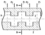
도 8은 채널(3) 내측의 장애물(9)의 방향(orientation)을 수반하는 또 다른 실시형태를 나타낸다. 본 실시예에 있어서, 장애물(9)은 채널의 길이방향 축선(T)에 수직인 유동 횡단면을 제공하며, 이 유동 횡단면은 길이방향 축선(T)을 따라 취해진 2개의 위치(P1 및 P2)들 사이에서 채널의 길이방향 축선(T)을 중심으로 회전한다. 이러한 유동 횡단면은, 채널의 양단부 사이에서 비연속적인 방식으로 회전하며, 다시 말해서 장애물의 길이는 채널의 길이보다 짧다. 예를 들어, 장애물(9)은 적어도 하나의 나선형 표면의 형태를 가져서, 나선 부분이 채널의 입구와 출구 사이에서 나타나도록 한다. 본 실시형태에 있어서, 채널(3)의 횡단면은, 특히, 채널의 입구와 출구 사이에서 변화하는 형상 및 면적을 갖는다. 따라서, 적어도 그러한 장애물은 처리할 유체의 유동 방향으로 급작스럽게 좁아짐을 발생시킨다.Fig. 8 shows another embodiment involving the orientation of the
본 발명의 내용에 있어서, 다공성 서포트 또는 전체로서의 접선 유동 세퍼레이터 요소는, 첨가(additive) 기법을 이용함으로써 제조된다. 본 발명에 따른 방법은, 점진적으로 서포트의 3차원 구조를 만들어가도록 연속하여 서로에 중첩 및 본딩되는 개별적인 플라이(plies)를 형성함으로써 서포트의 3차원 구조를 만드는 것으로 이루어진다.In the context of the present invention, a tangential flow separator element as a porous support or as a whole is manufactured by using an additive technique. The method according to the invention consists in creating a three-dimensional structure of the support by forming individual plies which are successively superimposed and bonded to each other to progressively create a three-dimensional structure of the support.
이전 기술과 비교하여, 본 방법은 어떠한 공구 또는 기계 가공을 필요로 하지 않는 단일의 제조단계로 서포트를 만들 수 있다는 장점을 가지며, 그에 따라 서포트를 위한 다양한 형상에의 접근을 가능하게 하고, 채널 내의 장애물의 형상 및 치수를 변화시킬 수 있게 한다.Compared to the prior art, the method has the advantage that it can create support in a single manufacturing step that does not require any tools or machining, thereby allowing access to various features for support, Thereby making it possible to change the shape and dimensions of the obstacle.
분말과 같은 고체 재료를 이용할 때, 분말 베드(powder bed)의 두께 및 그에 따른 각각의 연속하여 경화되는 플라이(successively consolidated ply)의 두께는, 에너지를 적용함으로써 또는 액체를 분무함으로써, 아래쪽에 있는 플라이에 본딩될 수 있도록 비교적 작다. 특히, 분말은 20㎛ 내지 200㎛의 범위 내에 놓이는 두께로 적층되며, 여기서 이 두께는 선택된 첨가 기법의 함수이다.When using solid materials such as powders, the thickness of the powder bed and hence the thickness of each successively consolidated ply can be adjusted by applying energy or by spraying the liquid, Lt; / RTI > In particular, the powder is laminated to a thickness that lies in the range of 20 to 200 mu m, where this thickness is a function of the selected addition technique.
이것은, 소정의 3차원 형상을 제작하기 위해, 플라이 다음에 플라이를, 가능하게 하는 2진 시퀀스의 반복이다. 경화 패턴(consolidation pattern)은 하나의 플라이로부터 다른 플라이로 변화할 수 있다. 소정의 3차원 형상은 선택된 빌드-업(build-up) 축선을 따라서 형성된다.This is a repetition of the binary sequence which enables the ply after the ply to produce the desired three-dimensional shape. The consolidation pattern can change from one fly to another fly. The predetermined three-dimensional shape is formed along the selected build-up axis.
적층된 분말의 알갱이 크기는 분말의 각각의 베드를 위한 최소 두께를 결정하는 인자들 중 하나이며, 최종적으로 얻어지는 구멍의 평균 직경도 그렇다. 특히, 사용되는 분말은, 예컨대 금속 산화물 분말, 또는 그 전구체들 중 하나의 분말과 같은, 서포트를 구성하도록 하는 재료의 분말이다. 예를 들어, 적층된 분말은 대략 10㎛의 세라믹 서포트 내에 있어서의 평균구멍직경을 얻기 위해서 대략 35㎛의 평균입도크기를 가질 수 있다.The grain size of the laminated powder is one of the factors determining the minimum thickness for each bed of powder, and so is the average diameter of the resulting holes. In particular, the powder to be used is a powder of a material which makes it possible to form a support, for example a metal oxide powder, or a powder of one of its precursors. For example, the laminated powders may have an average particle size of about 35 占 퐉 to obtain an average pore diameter in a ceramic support of about 10 占 퐉.
본 출원인은, 재료의 선택, 및 주어진 재료에 대한, 사용되는 분말의 평균입도크기, 및 주어진 재료 및 주어진 알갱이 크기에 대한, 층 다음에 층이 반복되는 분말 베드의 두께와 같은 다양한 파라미터들을 조정함으로써, 그리고, 경화를 위하여 선택된 기술에 특정한 다양한 파라미터들을 조정함으로써, 양호하게 제어되는 방식으로 경화된 모놀리스(monolith) 내에 있어서의 잔여의 상호연결된 구멍 텍스처를 얻을 수 있다는 것을 발견하였다. 이러한 잔여의 구멍 텍스처는 알갱이들 사이의 상호연결된 보이드(voids)를 남겨두도록 분말 알갱이들의 제어된 소결(sintering)의 결과이다.Applicants have found that by adjusting the various parameters such as the choice of material and the average grain size of the powder used for a given material and the thickness of the powder bed in which the layer is repeated after the layer for a given material and a given grain size And by adjusting various parameters specific to the technique selected for curing, the residual interconnected hole texture in the cured monolith can be obtained in a well controlled manner. This residual hole texture is the result of the controlled sintering of the powder grains so as to leave interconnected voids between the grains.
에너지 빔을 이용할 때, 작용할 수 있는 메인 파라미터는, 초점 즉 분말의 베드에 충돌하는 빔의 직경, 분말의 베드가 광자 또는 전자의 빔에 의해 스캐닝되는 속도, 그리고 플라이를 구성하는 동안 에너지 빔의 충돌 면적들 사이의 중첩되는 비율(percentage)이다.When using an energy beam, the main parameters that can act are the diameter of the beam that impinges on the bed of the focus or powder, the rate at which the bed of powder is scanned by the beam of photons or electrons, It is the overlapping percentage between the areas.
액체 분무를 이용할 때, 작용할 수 있는 메인 파라미터는, 액적(drops)의 무게, 주파수, 분말 베드가 액적의 "제트(jet)"에 의해 스캐닝되는 속도, 그리고 연속하는 패스(passes) 동안에 중첩되는 비율이다.When using liquid spraying, the main parameters that can act are the weight of the drops, the frequency, the rate at which the powder bed is scanned by the "jet" of the droplet, and the rate of superposition during successive passes to be.
또한, 본 출원인은, 전술한 다양한 파라미터들을 모듈화함으로써, 구멍의 크기 분포를 조정할 수 있으며, 각각의 구멍의 주어진 개체군(population)에 대하여, 구멍의 개수 및 비틀림(tortuosity)을 제어할 수 있음을 관찰하였다.Applicants have also observed that by modulating the various parameters described above it is possible to adjust the size distribution of the holes and to control the number and tortuosity of the holes for a given population of each hole Respectively.
일단 분말이 선택된 구역 내에서 뭉쳐지면, 뭉쳐지지 않은 재료는 어떤 적절한 기술에 의해 제거된다. 사용되는 분말의 초기 유동성은 이러한 작업을 용이하게 한다. 또한, 만들어진 형상의 표면에 남아있는 분말의 최종 흔적을 제거하기 위해서 워터젯 기술이나 진동을 이용할 수도 있다.Once the powder is consolidated within the selected area, the unbonded material is removed by any suitable technique. The initial fluidity of the powder used facilitates this operation. Waterjet technology or vibration may also be used to remove the final traces of the powder remaining on the surface of the created feature.
필터 요소의 최종 경화 및 다공성 텍스처의 최종 상태는, 바인더를 제거(디-바인딩)하고/하거나 적절한 소결로 재료에 영향을 주는 것을 목적으로 하는 하나 이상의 이어지는(subsequent) 열처리에 의해 통상 얻어진다. 그러한 최종 소결을 위하여 선택되는 온도는 사용된 무기질 재료의 특성 및 사용된 분말의 평균입도크기의 함수이다.The final cure of the filter element and the final state of the porous textures are typically obtained by one or more subsequent heat treatments aimed at removing (de-binding) the binder and / or affecting the proper sintering furnace material. The temperature selected for such final sintering is a function of the nature of the mineral material used and the average particle size of the powder used.
따라서, 서포트 또는 나아가서 전체 접선 유동 세퍼레이터 요소는, 플라이 다음에 플라이를 쌓아올린다. 이를 위해, 조각들로 만들어지는 접선 유동 세퍼레이터 요소 또는 서포트의 3차원 구조 세분화를 시작하기 전에, 컴퓨터 지원설계(CAD)가 이용된다. 따라서, 만들어질 실제 3차원 목적물은 매우 얇은 두께의 2차원 조각으로 세분화된다. 그 다음에 이러한 얇은 조각들은, 소정의 3차원 형상을 점진적으로 쌓아올리도록 함께 중첩되어 본딩되는 개별적인 플라이의 형태로, 하나씩 만들어진다.Thus, the support or even the entire tangential flow separator element piles up the ply after the ply. To this end, a computer-aided design (CAD) is used before initiating the three-dimensional structural refinement of the tangential flow separator element or support made of pieces. Thus, the actual three-dimensional object to be made is subdivided into two-dimensional pieces of very thin thickness. These thin pieces are then made one by one in the form of individual plies which are superimposed and bonded together to gradually build up a predetermined three-dimensional shape.
이러한 3차원 구조는 다음과 같이 만들어진다:This three-dimensional structure is made as follows:
- 다음 단계들을 반복함으로써: - By repeating the following steps:
- 다공성 서포트를 형성하기 위한 고체 재료(유기질 또는 무기질 분말) 또는 액체 재료(분말이 분산(dispersed)된 액체 또는 유기질 전구체, 여기서 분말은 유기질 또는 무기질일 수 있음)의 베드를 만드는 단계로서, 상기 베드는 플라이의 수준에서 취해진 상기 다공성 서포트의 단면보다 큰 면적에 걸쳐 일정한 두께를 가지는 단계; 및 - making a bed of solid material (organic or inorganic powder) or liquid material (liquid or organic precursor in which the powder is dispersed, where the powder may be organic or inorganic) to form a porous support, Has a constant thickness over an area larger than the cross-section of the porous support taken at the level of the ply; And
- 앞선 플라이에 대해 이러한 방식으로 만들어지는 바와 같이 개별적인 플라이를 동시에 본딩하는 동안에, 개별적인 플라이를 생성하도록, 각각의 플라이에 대하여 결정되는 패턴을 형성하기 위한 재료의 일부의 국부적인 경화; Localized curing of a portion of the material to form the pattern determined for each ply, so as to produce a separate ply, while simultaneously bonding the individual plies as made in this manner for the preceding ply;
- 또는, 각각의 플라이에 대하여 소정의 패턴을 형성하도록 레이저의 빔으로 분무되는 유기질 또는 무기질 분말을 용융시킴에 의해 형성되는 재료의 연속적인 비드(beads)를 생성함으로써; Or by producing successive beads of material formed by melting organic or inorganic powders that are atomized with a beam of laser to form a pattern for each ply;
- 또는, 열 가용성(thermofusible) 고체 전구체의 스트링의 연속적인 또는 불연속적인 (적상(dropwise)) 용융에 의해.- or by continuous or discontinuous (dropwise) melting of a string of thermofusible solid precursors.
전구체가 그 자신에 이용되는 열 가용성 유기 폴리머일 때, 서포트는 유기질 특성을 가지며 유기질 특성의 층을 적층하기 위하여 즉시 이용될 수 있다. 전구체가 열 가용성 유기 폴리머 및 세라믹 또는 금속 무기질 본말의 혼합물일 때, 바인더로서 사용되는 폴리머가 제거된 다음에 그리고 무기질 분말의 알갱이들이 소결된 다음에, 서포트는 무기질 특성을 가진다.When the precursor is a thermally soluble organic polymer used for itself, the support has organic properties and can be used immediately to laminate layers of organic character. When the precursor is a mixture of a thermally soluble organic polymer and a ceramic or metallic mineral base, after the polymer used as a binder is removed and the granules of the inorganic powder are sintered, the support has inorganic properties.
일반적으로 방식으로, 제1 상태에 있어서, 사용되는 재료는 고체 또는 액체이며, 개별적인 플라이는 에너지를 전달함으로써 또는 미세한 액적으로 액체를 분무함으로써 경화된다. 에너지는, (발광 다이오드(LED)나 레이저에 의한) 통제된(directed) 광 빔을 이용함으로써, 또는 통제된 전자의 빔을 이용함으로써, 또는 CAD에 의해 선택된 패턴으로 분말의 베드에 걸쳐 포커싱 및 스캐닝될 수 있는 다른 어떤 에너지원을 이용함으로써, 국부화된 방식으로 전달될 수 있다. 그 다음에 에너지와 재료 사이의 상호작용은, 재료의 특성 및 사용되는 에너지원의 특성에 따라, 소결, 또는 재료용융 및 응고(solidifying), 또는 광-중합이나 광-교차-결합에 영향을 받은 재료가 생기게 한다.In a general manner, in the first state, the material used is solid or liquid, and individual plies are cured by transferring energy or by spraying the liquid with fine droplets. Energy can be obtained by using a directed light beam (by a light emitting diode (LED) or a laser) or by using a beam of controlled electrons, or by focusing and scanning across a bed of powder in a pattern selected by the CAD Or by using any other energy source that can be used, for example. The interaction between the energy and the material then depends on the nature of the material and the nature of the energy source being used to either sinter or melt and solidify the material or to influence the light- Material.
액체는 압전 시스템에 의해서 생성되는 마이크로 액적을 이용하여 국부화된 방식으로 전달될 수 있으며, 여기서 액적은 선택적으로 정전기장을 이용하여 대전되고 통제될 수 있다. 액체는, 바인더 또는 사전에 세라믹 분말에 부가되는 바인더를 활성화하기 위한 작용제이어야 한다.The liquid can be delivered in a localized fashion using microdroplets generated by the piezoelectric system, wherein the droplets can be selectively charged and controlled using an electrostatic field. The liquid should be a binder or an agent to activate the binder previously added to the ceramic powder.
이전의 기술에 비해, 본 발명의 내용에 있어서 예상되는 바와 같은 첨가 기술의 이용은, 첫째로 생산 신뢰성 및 속도의 측면에서 개선을 이룰 수 있으며, 둘째로 서포트 내측의 채널(들) 내에 형성될 수 있는 볼록부에 대한 형상 및 서포트 형상의 범위를 넓힐 수 있다.Compared to the prior art, the use of the addition technique as anticipated in the context of the present invention can be achieved firstly in terms of production reliability and speed, and secondly, in the channel (s) The shape of the convex portion and the range of the support shape can be widened.
본 발명의 내용에 있어서, 다양한 첨가 기술들이 이하 설명하는 바와 같이 3차원 형상을 설계하기 위하여 이용될 수 있다.In the context of the present invention, various addition techniques may be used to design a three-dimensional shape as described below.
선택적 레이저 소결(SLS) 또는 선택적 레이저 용융(SLM)Selective laser sintering (SLS) or selective laser melting (SLM)
이러한 기술로, 서포트 또는 접선 유동 세퍼레이터 요소를 구성하는 재료의 분말, 유기질 분말, 또는 금속으로 혹은 산화물, 질화물, 또은 탄화물 타입의 세라믹으로 만들어지는 무기질 재료의 분말, 또는 전구체를 위한 분말은, 연속적인 베드를 형성하도록 적층된다. 그 다음에 강력한 레이저 빔이, 선택된 패턴으로 국부적으로 적용되고, 서포트에 또는 접선 유동 세퍼레이터 요소에 상응하는 플라이를 형성하도록 분말을 뭉치기 위해 그리고 그것을 소결에 의해 앞선 플라이들에 본딩시키기 위해 작용한다. 국부화된 에너지 전달의 효과 하에서, 분말 알갱이들은 부분적으로 용융되어 함께 용접되어 가고, 그에 의해 플라이 화합(ply cohesive)을 이루고, 그에 따라 만들어진 형상의 사전-소결을 실시한다. 그 다음에, 새로운 분말 베드가 뿌려지고 프로세스가 다시 시작된다.With this technique, powders of the materials constituting the support or tangential flow separator elements, powders of organic materials, or powders of inorganic materials made of metal, or of oxides, nitrides or ceramics of the carbide type ceramic, or powders for precursors, To form a bed. A powerful laser beam is then applied locally to the selected pattern and acts to bond the powder to the support and to form a ply corresponding to the tangential flow separator element and to bond it to the preceding plies by sintering. Under the effect of localized energy transfer, the powder granules are partially melted and welded together, thereby forming a ply cohesive and thereby effecting a pre-sintering of the shape produced. Then, a new powder bed is sprayed and the process is resumed.
레이저 빔은 플라이 하나씩 소정의 패턴으로 재료를 경화시키도록 분말의 표면을 스캐닝한다. 이 스캐닝은 평행한 경로를 따라서 레이저를 이동시킴으로써 수행된다. 레이저의 충돌 면적이 2개의 연속하는 평행한 경로 사이에서 중첩되도록 하는 것이 유리할 수 있다. 레이저 빔의 충돌 위치에서 분말 베드에 의해 수용되는 에너지의 양은 분말 알갱이들의 용융이 부분적으로 남아있도록, 또는 어떤 경우에도 각각의 알갱이가 다공성 텍스처를 폐쇄함 없이 가장 가깝게 이웃하는 알갱이와 본딩되기에 충분하게 용융되도록 하여야 한다.The laser beam scans the surface of the powder to cure the material in a predetermined pattern, one by one of the ply. This scanning is performed by moving the laser along a parallel path. It may be advantageous to have the impact area of the laser overlap between two successive parallel paths. The amount of energy received by the powder bed in the collision position of the laser beam is such that the melting of the powder particles remains partially or in some cases sufficient to allow each grain to be bonded to the nearest neighboring grains without closing the porous texture It should be melted.
따라서 기계의 조정은 특히 분말 베드의 고유한 특성에 그리고 광자와 재료 사이의 상호작용의 유효성을 한정하는 재료 특성에 따른다.The adjustment of the machine therefore depends, in particular, on the inherent characteristics of the powder bed and on the material properties that define the effectiveness of the interaction between the photon and the material.
참고로, 아래의 표 1에서 설정된 범위에 상응하는 조건을 이용할 수 있다.For reference, conditions corresponding to the range set in Table 1 below can be used.
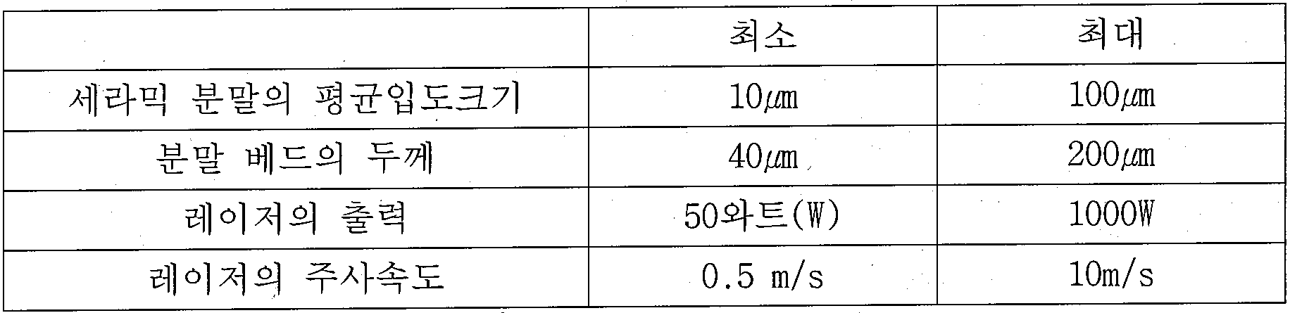
레이저 빔의 초점 및/또는 빔의 주사속도를 국부적으로 조정함으로써, 분말 베드에 의해 수용되는 에너지의 양을 조정할 수 있으며, 그에 따라 다공성 텍스처를 조정할 수 있다. 따라서, 어느 하나의 위치에서는, 필터 세퍼레이터 층에 대하여 요구되는 것에 상응하는 다공성 텍스처를 얻을 수 있으며, 또 다른 위치에서는, 서포트를 위하여 요구되는 것에 상응하는 다공성 텍스처를 얻을 수 있다.By locally adjusting the focus of the laser beam and / or the scanning speed of the beam, it is possible to adjust the amount of energy received by the powder bed, thereby adjusting the porous texture. Thus, at any one location, a porous texture corresponding to that required for the filter separator layer can be obtained, and at another location, a porous texture corresponding to that required for support can be obtained.
비록 소결은 레이저를 적용함으로써 서포트 또는 접선 유동 세퍼레이터 요소를 쌓아올리는 동안에 점진적으로 수행되지만, 서포트 또는 접선 유동 세퍼레이터 요소가 완전히 만들어진 후, 잔류하는 기계적인 응력을 해제하기 위해서 그리고 다공성 텍스처를 더욱 균일한 만들기 위해서, 최종 소결 단계를 이용하는 것이 유리하다. 그러한 최종 소결을 위하여 선택되는 온도는, 이용되는 무기질 재료의 특성 및 이용되는 분말의 평균입도크기의 함수이어야 하며, 예를 들어, 산화티타늄을 이용할 때, 1300℃ 내지 1500℃의 범위 내의 온도가 이용되어야 한다.Although sintering is performed incrementally during the stacking of the support or tangential flow separator elements by the application of a laser, but after the support or tangential flow separator element has been fully formed, to release the residual mechanical stress and to make the porous texture more uniform , It is advantageous to use the final sintering step. The temperature selected for such final sintering should be a function of the characteristics of the inorganic material used and the average particle size of the powder utilized, for example, when using titanium oxide, a temperature in the range of 1300 ° C to 1500 ° C is utilized .
전술한 분말의 선택적 용융은 전자 빔에 의해 유사한 방식으로 얻어질 수 있음을 알 수 있으며, 이것은 전자 빔 용융(EBM) 기술에 상응한다.It can be seen that the selective melting of the above-mentioned powders can be obtained in a similar manner by an electron beam, which corresponds to an electron beam melting (EBM) technique.
3D 프린팅3D printing
원리는 동일하게 남아있지만, 프린팅으로 적층된 플라이는 유기질이나 무기질, 세라믹 또는 금속성일 수 있는 분말 혼합물에 상응할 수 있으며, 이 분말은 서포트를 구성하는 재료, 또는 그 재료의 전구체일 수 있으며, 이 전구체는, 바인더와 함께, 분말 또는 무기질 분말 상의 코팅층의 형태일 수 있다. 바람직하게는, 혼합물은 균일하며, 서포트를 구성하는 재료 또는 그 재료를 위한 전구체의 분말 입자, 그리고 바인더의 입자는 유사한 크기를 갖는다. 바인더의 예로서, 푸란 수지, 페놀 수지 및 아미노 수지를 들 수 있다. 바인더의 중량 퍼센트는 그 특성 및 사용되는 분말의 평균직경에 따라 1% 내지 25%의 범위 내에 놓인다. 그 다음에, 바인더를 활성화시키는 작용제는, 매우 미세한 액적의 형태로 선택된 패턴으로 분무되어, 분말이 국부적으로 뭉치도록 야기시킨다. 활성화 작용제는 바인더를 위한 용제일 수 있으며, 거의 즉각적으로 건조된 후, 무기질 입자들을 함께 끈끈하게 결합시키거나 입자들을 고체 격자 내측에 감금하도록 작용한다.Although the principle remains the same, the plies laminated by printing may correspond to a powder mixture which may be organic or inorganic, ceramic or metallic, which powder may be the material of the support, or a precursor of the material, The precursor, together with the binder, may be in the form of a powder or a coating layer on an inorganic powder. Preferably, the mixture is homogeneous, the powder particles of the precursor for the material constituting the support or the material, and the particles of the binder have a similar size. Examples of the binder include a furan resin, a phenol resin and an amino resin. The weight percent of the binder is in the range of 1% to 25%, depending on its characteristics and the average diameter of the powder used. Then, the agent activating the binder is sprayed in a selected pattern in the form of very fine droplets, causing the powder to aggregate locally. The activating agent may be a solvent for the binder, and after nearly immediate drying, acts to bond the inorganic particles together or to confine the particles inside the solid lattice.
또한, 연속적인 베드를 형성하기 위해서, 단지 서포트를 구성하는 재료의 유기질이나 무기질, 세라믹 또는 금속성 분말, 또는 그 전구체의 분말을 적층시키고, 국부적으로 바인더를 분무할 수 있으며, 여기서 바인더는 급속-건조 액체 접착제 또는 열경화성 액체 수지일 수 있다.Further, in order to form a continuous bed, it is possible to laminate an organic or inorganic material, a ceramic or a metallic powder of a material constituting the support, or a powder of the precursor thereof, and to spray the binder locally, A liquid adhesive or a thermosetting liquid resin.
액체 형태의 바인더 또는 활성화 작용제는 어떠한 적절한 장치, 특히 잉크젯 타입 프린터에서 사용되는 종류의 압전 시스템 등을 이용함으로써 분무되고, 여기서 스캐닝은 평행한 경로를 따라서 프린트 헤드를 움직임으로써 수행될 수 있다. 2개의 연속적인 평행한 경로들 사이에서 액적의 충돌 면적이 중첩되는 것이 유리할 수 있다.The liquid type binder or activating agent is sprayed by using any suitable apparatus, particularly a piezoelectric system of the kind used in an ink jet type printer, where scanning can be performed by moving the print head along a parallel path. It may be advantageous to overlap the area of impact of the droplets between two successive parallel paths.
뭉쳐지지 않은 분말을 제거한 후, 바인더는 소결 열처리 동안에 제거되며, 이러한 디바인딩(debinding)은 500℃에 도달하기 전에 통상 끝난다.After removing the unbundled powder, the binder is removed during the sintering heat treatment, and such debinding usually ends before reaching 500 占 폚.
세라믹 분말의 알갱이가 30㎛ 내지 100㎛의 범위 내에 놓이는 평균 크기를 갖는 경우에, 3D 프린팅은 80㎛ 내지 300㎛의 범위 내에 놓이는 두께로 분말 베드를 만들도록 할 수 있고 25 mm/h 내지 100 mm/h의 범위 내에 놓이는 소정 형상을 위한 선형 구성 속도(linear construction speeds)에 도달하도록 할 수 있다.In the case where the grains of the ceramic powder have an average size lying within a range of 30 탆 to 100 탆, the 3D printing can be made to produce a powder bed with a thickness falling within a range of 80 탆 to 300 탆, / h < / RTI > for a given geometry.
리소그래피-기반 세라믹 제조(LCM)Lithography-Based Ceramic Manufacturing (LCM)
LCM은 세라믹 분말이 광-중합가능 수지와 사전-혼합되는 기술이며, 여기서 중합에 의한 경화가 LED 또는 레이저 광원을 이용하여 얻어진다. 전술한 기술에서와 같이, 바인더를 제거하도록 작용하는 소결 열 사이클 전에 비-교차-결합된 분말을 제거할 필요, 즉, 적절한 소결이 이어지게 광-중합가능 수지를 제거할 필요가 있다. LCM의 이용은, 광의 충돌 지점 아래 및 주변에서의 벌크 중합을 성취하기 위해서 분말 알갱이가 경화 아래에서의 파장에서 투명해야 한다는 사실에 의해 제한된다.LCM is a technique in which a ceramic powder is pre-mixed with a photo-polymerizable resin, wherein curing by polymerization is obtained using an LED or laser light source. As in the above description, it is necessary to remove the non-cross-linked powder before the sintering thermal cycle which serves to remove the binder, i.e., to remove the photo-polymerizable resin so that proper sintering is continued. The use of LCM is limited by the fact that powder grains must be transparent at wavelengths below curing in order to achieve bulk polymerization below and around the point of collision of light.
융합 적층(Fused deposition) 모델링(FDM)Fused deposition modeling (FDM)
FDM은 추가되는 무기질 분말을 선택적으로 가지는 열융합성 고체 유기 폴리머를 이용하는 기술이다. 이러한 기술은 스트링 또는 테이프로부터 재료의 비드의 연속적인 적층을 야기시키도록 시도한다. 재료의 비드는, 연속적으로(압출) 또는 불연속적으로(액적), 스트링 또는 테이프의 말단을 연화(softening) 또는 용융시킴으로써 만들어진다. 전술한 기술과는 달리, 사전에 재료의 베드를 형성하지 않는다. 재료의 비드 또는 플라이는 열에 의해 경화된다.FDM is a technique using a thermally fusible solid organic polymer having an optional inorganic powder added thereto. This technique attempts to cause continuous stacking of beads of material from a string or tape. The beads of the material are made by continuously (extruding) or discontinuously (droplet), softening or melting the ends of the string or tape. Unlike the techniques described above, no bed of material is formed in advance. The beads or ply of material are cured by heat.
본 기술의 변형예에 있어서, 재료의 연속적인 비드를 생성하기 위해서, 무기질 분말을 분무하도록 준비가 이루어질 수 있으며, 여기서 이 분말은 충돌 전에 용융되도록 레이저 빔 내로 분무된다.In a variant of the technique, in order to produce a continuous bead of material, it may be prepared to spray an inorganic powder, wherein the powder is sprayed into the laser beam to be melted before impact.
광조형(stereolithography) 장치를 이용한 광조형(SLA)Optical stereolithography (SLA) using a stereolithography device
전술한 기술들과 원칙적으로 유사한 이 기술은, 합체된 무기질 분말을 가지는 광경화성(photocurable) 액체 전구체로서 액체 재료를 이용한다. 광자의 빔(LED 또는 레이저)은 액체 층을 스캐닝하여 그것을 국부적으로 중합시킨다.This technique, which is principally similar to the techniques described above, uses a liquid material as a photocurable liquid precursor with incorporated inorganic powders. The beam of photons (LED or laser) scans the liquid layer and locally polymerizes it.
3D 프린팅 또는 LCM으로, 필터 세퍼레이터 층(들)은, 최종 소결 작업 이후에, 서포트가 만들어진 후 적층된다. 세퍼레이터 층은, 베이킹 후 필터 층을 구성하도록 하는 적어도 하나의 소결가능한 조성(sinterable composition)을 함유하는 현탁액(suspension)을 그 위에 적층함으로써, 서포트의 채널 내의 장애물 및 채널의 표면 상에 적층된다. 그러한 조성은 무기질 필터 멤브레인의 제조시 통상적으로 사용되는 것과 같은 구성(constitution)을 제공한다. 이 조성은 적어도 하나의 산화물, 질화물, 탄화물, 또는 다른 세라믹 재료, 또는 그 혼합물을 함유하며, 여기서 금속 산화물, 질화물, 및 탄화물이 바람직하다. 소결가능한 조성은 예를 들어 물과 같은 현탁액 내에 더해진다. 결집체(aggregates)가 존재할 우려를 제거하기 위해서 그리고 액체 내의 알갱이의 분산을 최적화하기 위해서, 최종 현탁액은 결집체를 파괴하여 본질적으로 개별적인 입자들을 구성하는 조성을 얻도록 밀링(milled)된다. 그 다음에 현탁액의 유동성(rheology)은 서포트의 채널 내로 침투하기 위한 수력학적 요구조건을 만족하기 위해서 유기 첨가물로 조정된다. 일단 층이 적층되면, 건조되고, 그 다음에, 해당 특성, 알갱이의 평균 크기, 및 의도되는 컷-오프 역치(cut-off threshold)에 따른 온도로 소결된다.With 3D printing or LCM, the filter separator layer (s) are laminated after the final sintering operation, after the support is made. The separator layer is deposited on the surface of the channel and the obstacles in the channels of the support by laminating thereon a suspension containing at least one sinterable composition that allows the filter layer to form after baking. Such a composition provides the same constitution as is commonly used in the manufacture of inorganic filter membranes. The composition contains at least one oxide, nitride, carbide, or other ceramic material, or a mixture thereof, wherein metal oxides, nitrides, and carbides are preferred. The sinterable composition is added into a suspension such as, for example, water. In order to eliminate the concern that aggregates are present and to optimize the dispersion of the particles in the liquid, the final suspension is milled to break the aggregate and essentially obtain a composition that constitutes individual particles. The rheology of the suspension is then adjusted to an organic additive to meet the hydrodynamic requirements for penetration into the channels of the support. Once the layers are stacked, they are dried and then sintered to a temperature corresponding to the properties, the average size of the grains, and the intended cut-off threshold.
SLS 또는 SLM으로, 세퍼레이터 필터 층(들)은 서포트를 쌓아올림과 동시에 생성될 수 있거나, 멤브레인 제조시 사용되는 종래의 적층 방법을 이용하여 나중에 적층될 수 있다. 또, 세퍼레이터 필터 층(들)은 적층될 무기질 재료 또는 그 전구체의 입자들의 현탁액으로부터 적층될 수 있다. 그러한 현탁액은 세라믹 필터 요소의 제조시 관례적으로 사용되고 있다. 건조 후, 상기 층에 대해, 층을 경화하도록 작용하는, 그리고 적층되는 표면에 층을 결합하는 소결 작업이 실시된다. 현탁액 내에 제공되는 입자들의 알갱이 크기는 세퍼레이터 필터 층을 위한 소정의 최종 다공성 텍스처의 함수이다.With SLS or SLM, the separator filter layer (s) can be created at the same time as the support is built up, or can be laminated later using conventional lamination methods used in the manufacture of membranes. The separator filter layer (s) may also be deposited from a suspension of particles of the inorganic material or precursors thereof to be deposited. Such suspensions are customarily used in the manufacture of ceramic filter elements. After drying, a sintering operation is performed for the layer, which acts to harden the layer and bonds the layer to the surface to be laminated. The grain size of the particles provided in the suspension is a function of the desired final porous texture for the separator filter layer.
이어지는 실시예들은 본 발명을 예시하며, 본 발명을 한정하지 않는다.The following examples illustrate the invention and do not limit the invention.
도면에 도시된 타입의, 접선 유동 분리(separation)를 위한 관형 요소는, 본 발명에 따라 제조되었다. 서포트는, 복수의 직선형 채널들이 튜브의 축선에 평행하게 형성되는 상태로, 300mm 내지 1200mm의 범위 내에 놓이는 길이를 가지며, 횡단면이 원형이며, 10mm 내지 42mm의 범위 내에 놓이는 직경을 가지는 튜브의 형태를 갖는다.A tubular element for tangential flow separation of the type shown in the figures was produced in accordance with the present invention. The support is in the form of a tube having a length lying within a range of 300 mm to 1200 mm with a plurality of straight channels formed parallel to the axis of the tube and having a circular cross section and a diameter lying within a range of 10 mm to 42 mm .


그러한 환경 아래에서, 최종 소결은 필요하지 않다.Under such circumstances, final sintering is not required.
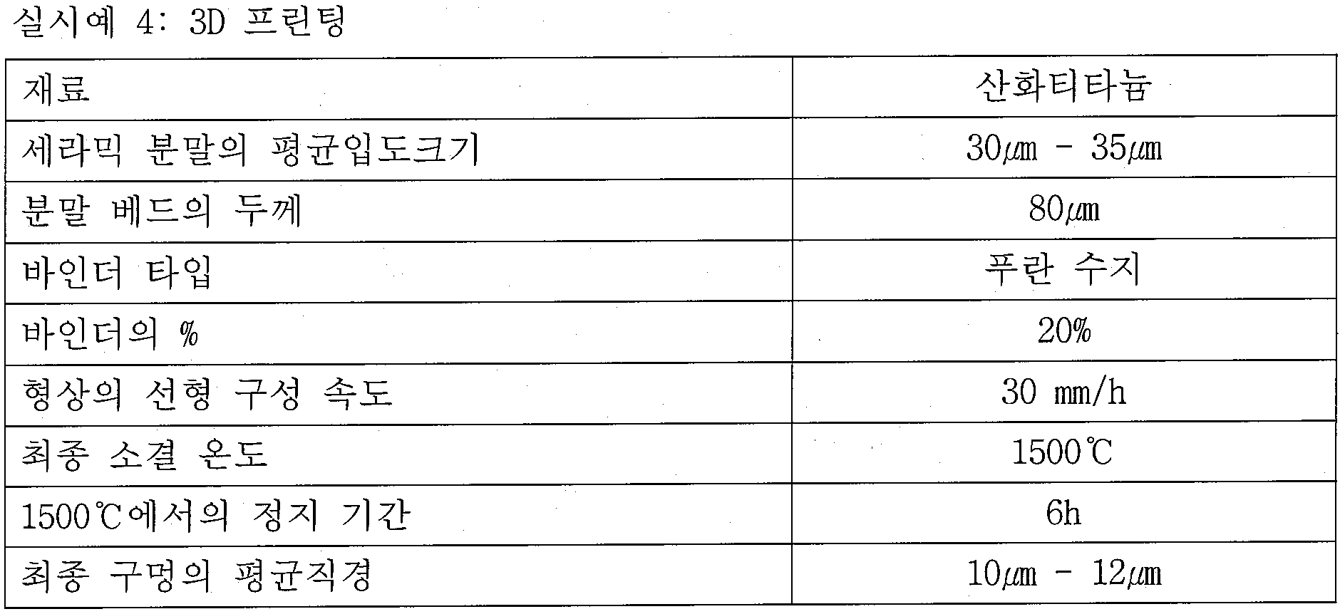
실시예 1, 3, 및 4에 있어서, 접선 유동 세퍼레이터 요소의 제조는, 아래 현탁액을 이용함으로써 채널의 표면 상에 세퍼레이터 층을 적층시킴에 의해 완료되었다.In Examples 1, 3 and 4, the production of the tangential flow separator element was completed by laminating the separator layers on the surface of the channel by using the lower suspension.
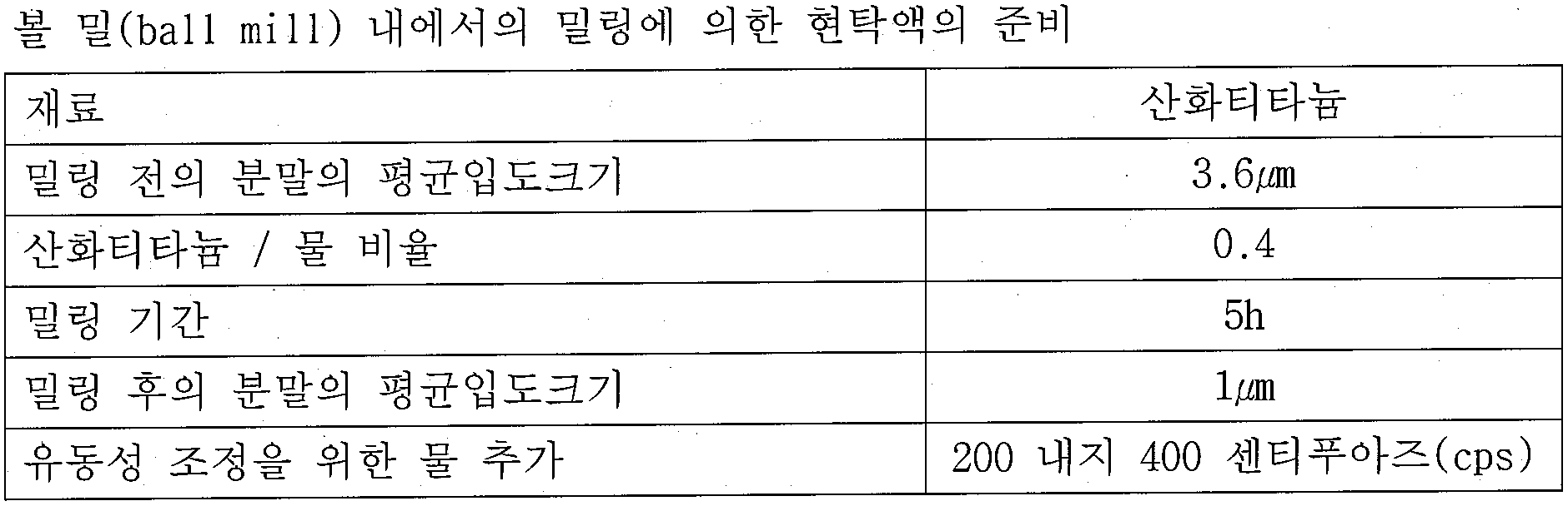
1.4㎛의 컷-오프 역치를 갖는 마이크로여과 세퍼레이터 층은 다음 방식으로 수행되는 서포트에 대한 직접 적층(direct deposition) 이후에 얻어졌다.A microfiltration separator layer with a cut-off threshold of 1.4 mu m was obtained after direct deposition for a support performed in the following manner.
현탁액은 채널의 표면과 접촉하도록 하기 위해서 펌핑에 의해 채널 내로 침투되도록 야기시켰다. 적층을 유도하는 메카니즘은 다공성 서포트의 구멍들을 통하여 유인되는 현탁액으로부터의 액체였다.The suspension was caused to penetrate into the channel by pumping to bring it into contact with the surface of the channel. The mechanism for inducing lamination was the liquid from the suspension that was drawn through the holes of the porous support.
표면에 대한 산화티타늄 입자의 적층 두께, 그리고 그에 따른 단위면적당 적층된 무게는, 서포트의 채널 내에서 현탁액에 의해 소비된 시간에 따른다.The lamination thickness of the titanium oxide particles on the surface, and thus the laminated weight per unit area, depends on the time spent by the suspension in the channel of the support.

대략 110 g/㎡의 최종 적층 무게에 도달하도록 작업이 2번 반복되었다.The operation was repeated twice to reach a final lamination weight of approximately 110 g / m < 2 >.

1.4㎛보다 작은 컷-오프 역치를 갖는 접선 유동 마이크로여과 세퍼레이터 요소 그리고 접선 유동 울트라여과 및 나노여과 세퍼레이터 요소는, 적절한 열처리 사이클로 점점 더 미세해지는 현탁액을 이용하여, 첫 번째 층 위로 연속적인 적층을 수행함으로써 제조될 수 있다.Tangential flow microfiltration separator elements and tangential flow ultra filtration and nanofiltration separator elements with cut-off thresholds less than 1.4 microns can be obtained by performing successive stacking over the first layer using a suspension that becomes increasingly finer with an appropriate heat treatment cycle .
다양한 변형이 본 발명의 범주를 벗어남 없이 이루어질 수 있으므로, 본 발명은 설명되고 도시된 실시예로 한정되지 않는다.Various modifications may be made without departing from the scope of the present invention, and thus the present invention is not limited to the embodiments described and illustrated.
Claims (18)
상기 세퍼레이터 요소는 3차원 구조의 직선형 강체 다공성 서포트(2)를 포함하되 상기 서포트는 서포트의 외측 표면(5)으로부터 여과액을 회수하기 위해서 처리할 유체 매질의 유동을 통과시키기 위한 적어도 하나의 채널(3)이 내부에 배열되며, 상기 서포트의 외측 표면(5)은 일정한 프로파일을 가지는, 모놀리식 접선 유동 세퍼레이터 요소에 있어서,
모놀리식 강체 다공성 서포트(2)는 채널(들)의 내측 벽(들) 상에 또는 내에 여과할 유체의 유동에 대한 장애물(9)을 포함하며,
상기 장애물(9)은 서포트와 다공성 텍스처 및 재료의 동질성(identity) 그리고 서포트와 다공성 텍스처 및 재료의 연속성을 가지며,
채널의 길이방향 축선(T)을 따라서 취해지는 제1 위치(P1)와 제2 위치(P2) 사이에서 나타나는 바와 같이, 상기 장애물(9)은, 유체의 유동을 저해하거나 방해하기 위해서 상기 채널 내에서 처리할 유체의 유동방향으로 급작스럽게 좁아지거나 수렴하는 노즐을 생성하는 것을 특징으로 하는, 모놀리식 접선 유동 세퍼레이터 요소.A monolithic tangential flow separator element for separating a fluid medium to be treated into a filtrate and a concentrate,
The separator element comprises a three-dimensional, rigid rigid porous support (2) having at least one channel for passing the flow of the fluid medium to be treated to recover the filtrate from the outer surface (5) of the support 3) are arranged in the outer surface (5) of the support and the outer surface (5) of the support has a constant profile, the monolithic tangential flow separator element
The monolithic rigid porous support 2 comprises an obstacle 9 for the flow of fluid to be filtered on or in the inner wall (s) of the channel (s)
The obstacle 9 has an identity between the support and the porous textures and materials and continuity of the support and the porous textures and materials,
The obstacle 9 is positioned within the channel 12 to prevent or impede the flow of fluid, as shown between a first position P1 and a second position P2 taken along the longitudinal axis T of the channel. To produce a nozzle that rapidly or narrows in the direction of flow of the fluid to be treated in the tangential flow separator element.
입구(6)와 출구(7) 사이에서, 장애물(9)을 구비하는 적어도 하나의 채널(3)은, 변화하는 형상 및/또는 면적 및/또는 윤변(wetted perimeter) 및/또는 수력직경(hydraulic diameter)의 유동 횡단면을 가지는 것을 특징으로 하는, 모놀리식 접선 유동 세퍼레이터 요소.The method according to claim 1,
Between the inlet 6 and the outlet 7 at least one channel 3 with an obstacle 9 has a variable shape and / or area and / or a wetted perimeter and / or a hydraulic diameter flow cross-sectional area of the tangential flow separator element.
채널(3)의 적어도 하나의 장애물(9)은 상기 장애물의 위치에서 국부적으로 좁아지는 유동 횡단면을 생성하며,
상기 유동 횡단면은, 상기 채널의 길이방향 축선(T)에 수직이고, 상기 장애물로부터 상류 및 하류측에 위치된 채널 부분의 형상(들)과는 상이한 형상을 가지는 것을 특징으로 하는, 모놀리식 접선 유동 세퍼레이터 요소.The method according to claim 1 or 2,
At least one obstacle (9) of the channel (3) creates a flow cross-section that locally narrows at the location of the obstacle,
Characterized in that the flow cross-section has a shape which is perpendicular to the longitudinal axis (T) of the channel and which is different from the shape (s) of the channel portion located upstream and downstream from the obstacle, Flow separator element.
가장 좁은 유동 횡단면과, 채널(3)의 상기 가장 좁은 유동 횡단면으로부터 상류측에 위치된 부분과의 사이에서, 다음 리스트로부터 취해진 기준들 중 하나는 변화하지 않고 유지되는 한편 다른 기준들은 변화하며, 상기 기준은: 채널의 유동 횡단면의 형상, 면적, 윤변, 및 수력직경인 것을 특징으로 하는, 모놀리식 접선 유동 세퍼레이터 요소.4. The method according to any one of claims 1 to 3,
Between the narrowest flow cross-section and the portion located upstream from the narrowest flow cross-section of the channel 3, one of the criteria taken from the following list remains unchanged while the other criteria change, The reference is: the shape, area, circumference, and hydraulic diameter of the flow cross-section of the channel.
가장 좁은 유동 횡단면과, 채널의 상기 가장 좁은 유동 횡단면으로부터 상류측에 위치된 부분과의 사이에서, 다음 리스트로부터 취해진 기준들 모두는 변화하지 않고 유지되며, 상기 기준은: 형상, 면적, 윤변, 및 수력직경인 것을 특징으로 하는, 모놀리식 접선 유동 세퍼레이터 요소.The method of claim 3,
Between the narrowest flow cross-section and the portion located upstream from the narrowest flow cross-section of the channel, all of the references taken from the following list remain unchanged, and the criterion is: shape, area, Characterized in that the hydrodynamic tangential flow separator element is a hydraulic diameter.
채널(3)의 적어도 하나의 장애물(9)은 상기 채널의 길이방향 축선(T)에 수직인 유동 횡단면을 가지며,
상기 유동 횡단면은 채널의 길이방향 축선을 따라서 취해진 2개의 위치 사이에서 상기 채널의 길이방향 축선을 중심으로 회전하는 것을 특징으로 하는, 모놀리식 접선 유동 세퍼레이터 요소.6. The method according to any one of claims 1 to 5,
At least one obstacle (9) of the channel (3) has a flow cross section perpendicular to the longitudinal axis (T) of the channel,
Characterized in that the flow cross-section is rotated about the longitudinal axis of the channel between two positions taken along the longitudinal axis of the channel.
채널(3)의 적어도 하나의 장애물(9)은, 상기 채널의 양단부 사이에서 불연속적인 방식으로 상기 채널의 길이방향 축선을 중심을 회전하는 유동 횡단면을 가지는 것을 특징으로 하는, 모놀리식 접선 유동 세퍼레이터 요소.The method of claim 6,
Characterized in that at least one obstacle (9) of the channel (3) has a flow cross-section which rotates about the longitudinal axis of the channel in a discontinuous manner between the opposite ends of the channel, the monolithic tangential flow separator Element.
채널(3)의 내측 벽(31) 상에 연속적으로 적층되고 상기 장애물(9)을 완전히 덮는 적어도 하나의 세퍼레이터 층(4)을 포함하는 것을 특징으로 하는, 모놀리식 접선 유동 세퍼레이터 요소.The method according to any one of claims 1 to 7,
Channel 3, the inner wall (31) is continuously laminated on the obstacle (9) completely covers the monolithic tangential flow separator element, it characterized in that it comprises at least one of the separator layer 4.
다공성 서포트(2)는 유기질 또는 무기질인 재료로 만들어지는 것을 특징으로 하는, 모놀리식 접선 유동 세퍼레이터 요소.The method according to any one of claims 1 to 8,
A monolithic tangential flow separator element, characterized in that the porous support (2) is made of an organic or inorganic material.
세퍼레이터 층 또는 중간 층은 유기질 또는 무기질인 재료로 만들어지는 것을 특징으로 하는, 모놀리식 접선 유동 세퍼레이터 요소.The method according to claim 8 or 9,
Characterized in that the separator layer or the intermediate layer is made of an organic or inorganic material.
다공성 서포트(2)의 3차원 구조는 광학 현미경 또는 주사 전자 현미경에 의해 관찰될 수 있는 재료의 상이한 플라이(plies)들을 가지는 것을 특징으로 하는, 모놀리식 접선 유동 세퍼레이터 요소.The method according to any one of claims 1 to 10,
Characterized in that the three-dimensional structure of the porous support (2) has different plies of material which can be observed with an optical microscope or a scanning electron microscope.
서포트의 3차원 구조는 소정의 3차원 형상을 점진적으로 쌓아올리도록 서로 중첩되어 연속적으로 본딩되는 개별적인 플라이들을 형성함으로써 이루어지는, 방법.A method of manufacturing a monolithically tangential flow separator element (1) according to any one of claims 1 to 11,
Wherein the three-dimensional structure of the support is formed by forming individual plies which are superimposed on one another and successively bonded to gradually build up a predetermined three-dimensional shape.
다음 단계들:
- 다공성 서포트를 형성하기 위한 재료의 연속적인 베드를 만드는 단계로서, 상기 베드는 플라이에서의 상기 다공성 서포트의 단면보다 큰 면적에 걸쳐 일정한 두께를 가지는, 단계; 및
- 개별적인 플라이를 생성하도록, 각각의 플라이에 대하여 결정되는 패턴을 형성하기 위하여 재료의 일부를 국부적으로 경화하는 한편, 이러한 방식으로 만들어지는 바와 같은 개별적인 플라이를 앞선 플라이에 대해 동시에 본딩하는 단계;
를 반복함으로써 3차원 구조를 만드는 것을 특징으로 하는, 방법.The method of claim 12,
Next steps:
Making a continuous bed of material for forming a porous support, said bed having a constant thickness over an area larger than the cross-section of said porous support in the ply; And
- locally curing a portion of the material to form a pattern determined for each ply, while simultaneously bonding the individual plies as made in this manner to the preceding ply, so as to produce an individual ply;
Lt; RTI ID = 0.0 > a < / RTI > three-dimensional structure.
광중합 가능한 수지와 같은 액체 재료 또는 분말의 형태인 고체 재료의 연속적인 베드를 만드는 단계를 포함하는 것을 특징으로 하는, 방법.14. The method of claim 13,
Characterized in that it comprises the step of making a continuous bed of solid material in the form of a liquid material or powder such as a photopolymerizable resin.
유기질 또는 무기질 분말의 형태인 고체 재료의 연속적인 베드를 만드는 단계를 포함하는 것을 특징으로 하는, 방법.The method according to any one of claims 12 to 14,
Characterized in that it comprises the step of making a continuous bed of solid material in the form of an organic or inorganic powder.
내부에 배치된 무기질 분말을 갖는 광중합 가능한 액체 전구체의 형태인 매질의 연속적인 베드를 만드는 단계를 포함하는 것을 특징으로 하는, 방법.The method of claim 12,
Comprising the step of making a continuous bed of medium in the form of a photopolymerizable liquid precursor having an inorganic powder disposed therein.
각각의 플라이는, 유기질 서포트 및 유기질 층을 이루도록 이용되는 열 가용성 유기 폴리머, 또는 무기질 특성의 서포트를 이루기 위한 세라믹 무기질 분말과 열 가용성 유기 폴리머의 혼합물인 열 가용성(thermofusible) 고체 전구체의 스트링의 연속적인 또는 불연속적인 용융에 의해 만들어지는 것을 특징으로 하는, 방법.The method of claim 12,
Each ply may be made of a thermally soluble organic polymer that is used to make an organic support and an organic layer, or a continuous, continuous layer of a string of thermofusible solid precursors that is a mixture of a ceramic inorganic powder and a thermally soluble organic polymer Or by discontinuous melting.
레이저 빔 내에서 용융되는 분말을 분무함으로써 재료의 연속적인 비드를 생성하는 단계를 포함하는 것을 특징으로 하는, 방법.The method of claim 12,
And generating a continuous bead of material by spraying a powder that is melted in the laser beam.
Applications Claiming Priority (3)
| Application Number | Priority Date | Filing Date | Title |
|---|---|---|---|
| FR1457745 | 2014-08-11 | ||
| FR1457745A FR3024665B1 (en) | 2014-08-11 | 2014-08-11 | TANGENTIAL FLOW SEPARATION ELEMENT INCLUDING TRAFFIC OBSTACLES AND MANUFACTURING METHOD |
| PCT/FR2015/052000 WO2016024058A1 (en) | 2014-08-11 | 2015-07-21 | Element intended for separation via tangential flow and having built-in flow obstacles, and manufacture method |
Publications (2)
| Publication Number | Publication Date |
|---|---|
| KR20170071476A true KR20170071476A (en) | 2017-06-23 |
| KR102406910B1 KR102406910B1 (en) | 2022-06-10 |
Family
ID=51862460
Family Applications (1)
| Application Number | Title | Priority Date | Filing Date |
|---|---|---|---|
| KR1020177006919A KR102406910B1 (en) | 2014-08-11 | 2015-07-21 | A tangential flow separator element incorporating flow obstacles, and method of fabrication |
Country Status (19)
| Country | Link |
|---|---|
| US (1) | US10293307B2 (en) |
| EP (1) | EP3180111B1 (en) |
| JP (1) | JP6783226B2 (en) |
| KR (1) | KR102406910B1 (en) |
| CN (1) | CN107155311B (en) |
| AU (1) | AU2015303084B2 (en) |
| CA (1) | CA2957159C (en) |
| DK (1) | DK3180111T3 (en) |
| ES (1) | ES2865110T3 (en) |
| FR (1) | FR3024665B1 (en) |
| HU (1) | HUE054157T2 (en) |
| MX (1) | MX2017001785A (en) |
| MY (1) | MY184860A (en) |
| NZ (1) | NZ729464A (en) |
| PH (1) | PH12017500256A1 (en) |
| PL (1) | PL3180111T3 (en) |
| PT (1) | PT3180111T (en) |
| RU (1) | RU2693159C2 (en) |
| WO (1) | WO2016024058A1 (en) |
Cited By (2)
| Publication number | Priority date | Publication date | Assignee | Title |
|---|---|---|---|---|
| US11643628B2 (en) | 2018-03-08 | 2023-05-09 | Repligen Corporation | Tangential flow depth filtration systems and methods of filtration using same |
| US11958018B2 (en) | 2019-03-08 | 2024-04-16 | Repligen Corporation | Tangential flow filtration systems and methods |
Families Citing this family (14)
| Publication number | Priority date | Publication date | Assignee | Title |
|---|---|---|---|---|
| FR3024663B1 (en) * | 2014-08-11 | 2020-05-08 | Technologies Avancees Et Membranes Industrielles | NOVEL GEOMETRIES OF TANGULAR FLOW SEPARATION SINGLE-CHANNEL TUBULAR ELEMENTS INCLUDING TURBULENCE PROMOTERS AND MANUFACTURING METHOD |
| FR3024665B1 (en) * | 2014-08-11 | 2020-05-08 | Technologies Avancees Et Membranes Industrielles | TANGENTIAL FLOW SEPARATION ELEMENT INCLUDING TRAFFIC OBSTACLES AND MANUFACTURING METHOD |
| FR3060410B1 (en) * | 2016-12-21 | 2019-05-24 | Technologies Avancees Et Membranes Industrielles | TANGENTIAL FLOW SEPARATION ELEMENT INTEGRATING FLEXIBLE CHANNELS |
| US20210060491A1 (en) * | 2018-01-12 | 2021-03-04 | Formulatrix, Inc. | Tangential flow filtration (tff) system and disposable tff unit that includes an integrated pump apparatus |
| FR3078330B1 (en) * | 2018-02-27 | 2020-03-13 | Dassault Aviation | HONEYCOMB STRUCTURE IN CERAMIC MATERIAL AND MANUFACTURING METHOD THEREOF |
| EP3553533B1 (en) * | 2018-04-12 | 2021-09-29 | Technische Universität Berlin | Boundary layer probe, measuring device and method for determining a fluid flow |
| JP7267307B2 (en) * | 2018-05-24 | 2023-05-01 | ゲーカーエン ドライブライン インターナショナル ゲゼルシャフト ミト ベシュレンクテル ハフツング | Plumbing fixture blanks, especially electrical inductor blanks |
| FR3088831B1 (en) * | 2018-11-27 | 2020-12-04 | Tech Avancees Et Membranes Industrielles | Manufacturing process by adding material from inorganic filtration media from a hot-melt filament and membrane obtained |
| FR3088832B1 (en) * | 2018-11-27 | 2022-01-14 | Tech Avancees Et Membranes Industrielles | Process for the manufacture by addition of material of inorganic filtration supports and membrane obtained |
| NL2025523B1 (en) * | 2020-05-07 | 2021-11-23 | Berghof Membrane Tech Gmbh | Tubular polymeric membrane, membrane module and device comprising such membrane and method and device for manufacturing |
| US20230321607A1 (en) * | 2020-08-17 | 2023-10-12 | InnoSpire Technologies GmbH | Monolithic Membrane Filters |
| DE102020121547A1 (en) * | 2020-08-17 | 2022-02-17 | InnoSpire Technologies GmbH | Monolithic ceramic membrane filters |
| DE102020121549A1 (en) * | 2020-08-17 | 2022-02-17 | InnoSpire Technologies GmbH | Monolithic membrane filter |
| FR3116446B1 (en) * | 2020-11-23 | 2022-11-25 | Tech Avancees Et Membranes Industrielles | Separation element of a liquid medium with high parietal shear stress |
Citations (5)
| Publication number | Priority date | Publication date | Assignee | Title |
|---|---|---|---|---|
| US4541976A (en) * | 1978-11-27 | 1985-09-17 | Commissariat A L'energie Atomique | Method of manufacturing cylindrical ceramic tubes having localized imprints on their inner faces |
| KR20110114542A (en) * | 2008-12-23 | 2011-10-19 | 생-고뱅 생트레 드 레체르체 에 데투드 유로삐엔 | Filtration structure having inlet and outlet surfaces with a different plugging material |
| WO2012032325A1 (en) * | 2010-09-08 | 2012-03-15 | Johnson Matthey Public Limited Company | Catalyst manufacturing method |
| WO2013144399A1 (en) * | 2012-03-30 | 2013-10-03 | Asociación De Investigación De La Industria Del Juguete, Conexas Y Afines | Method for the production of monolithic carbonaceous or ceramic systems |
| KR20140048895A (en) * | 2011-06-01 | 2014-04-24 | 밤 분데스안슈탈트 퓌어 마테리알포르슝 운트-프뤼풍 | Method for producing a moulded body and device |
Family Cites Families (18)
| Publication number | Priority date | Publication date | Assignee | Title |
|---|---|---|---|---|
| US2687997A (en) * | 1949-12-10 | 1954-08-31 | Marchand John Felix | Dialyzers |
| FR2503616A1 (en) | 1978-11-27 | 1982-10-15 | Commissariat Energie Atomique | Ceramic tubes with irregular flow cross=section - produced by indentation of extruded tube |
| FR2586362A1 (en) * | 1985-08-22 | 1987-02-27 | Sames Sa | DEVICE FOR FILTERING A GAS CHARGED WITH SOLID PARTICLES COMPRISING IMPROVED DECOLMATOUS MEANS |
| GB8725636D0 (en) * | 1987-11-02 | 1987-12-09 | Bellhouse Brian John | Transfer membrane apparatus |
| GB2223690B (en) * | 1988-10-17 | 1991-05-01 | Roger Stanley White | Filtration systems |
| GB9504908D0 (en) * | 1995-03-10 | 1995-04-26 | Bellhouse Brian John | Filter |
| FR2736843B1 (en) | 1995-07-19 | 1997-09-26 | Centre Nat Rech Scient | POROUS IMPRESSION TUBE FOR TANGENTIAL FILTRATION |
| US5785851A (en) * | 1996-08-23 | 1998-07-28 | Vesuvius Crucible Company | High capacity filter |
| JP2004000896A (en) * | 2002-03-25 | 2004-01-08 | Ngk Insulators Ltd | Honeycomb filter |
| FR2846255B1 (en) * | 2002-10-25 | 2005-01-28 | Tech Avancees & Membranes Ind | TANGENTIAL FILTRATION MEMBRANE AND METHOD OF MANUFACTURING THE SAME |
| US7469557B2 (en) * | 2004-06-12 | 2008-12-30 | Teresanne Griffin | Method for forming a capillary column for filtering, separation and concentration |
| US7261813B2 (en) * | 2004-08-10 | 2007-08-28 | Clemson University | Monolithic structures comprising polymeric fibers for chemical separation by liquid chromatography |
| RU2287358C1 (en) * | 2005-06-08 | 2006-11-20 | Николай Яковлевич ЗАЙЦЕВ | Separating filter element for cleaning and drying gases |
| KR101505938B1 (en) * | 2008-04-18 | 2015-03-25 | 스벤 멜커 닐손 | Channel system |
| CN202036928U (en) * | 2011-04-22 | 2011-11-16 | 吴克宏 | Single-channel low-voltage ceramic membrane component |
| BR112016002509A2 (en) * | 2013-08-14 | 2017-08-01 | Sumitomo Chemical Co | particulate filter |
| FR3024665B1 (en) * | 2014-08-11 | 2020-05-08 | Technologies Avancees Et Membranes Industrielles | TANGENTIAL FLOW SEPARATION ELEMENT INCLUDING TRAFFIC OBSTACLES AND MANUFACTURING METHOD |
| FR3024664B1 (en) * | 2014-08-11 | 2020-05-08 | Technologies Avancees Et Membranes Industrielles | NOVEL GEOMETRIES OF TANGENTIAL FLOW SEPARATION MULTI-CHANNEL TUBULAR ELEMENTS INCLUDING TURBULENCE PROMOTERS AND MANUFACTURING METHOD |
-
2014
- 2014-08-11 FR FR1457745A patent/FR3024665B1/en active Active
-
2015
- 2015-07-21 CA CA2957159A patent/CA2957159C/en active Active
- 2015-07-21 NZ NZ729464A patent/NZ729464A/en unknown
- 2015-07-21 MX MX2017001785A patent/MX2017001785A/en unknown
- 2015-07-21 ES ES15753395T patent/ES2865110T3/en active Active
- 2015-07-21 RU RU2017107791A patent/RU2693159C2/en active
- 2015-07-21 US US15/502,267 patent/US10293307B2/en active Active
- 2015-07-21 EP EP15753395.1A patent/EP3180111B1/en active Active
- 2015-07-21 PL PL15753395T patent/PL3180111T3/en unknown
- 2015-07-21 KR KR1020177006919A patent/KR102406910B1/en active IP Right Grant
- 2015-07-21 HU HUE15753395A patent/HUE054157T2/en unknown
- 2015-07-21 JP JP2017507694A patent/JP6783226B2/en active Active
- 2015-07-21 WO PCT/FR2015/052000 patent/WO2016024058A1/en active Application Filing
- 2015-07-21 CN CN201580043489.3A patent/CN107155311B/en active Active
- 2015-07-21 PT PT157533951T patent/PT3180111T/en unknown
- 2015-07-21 AU AU2015303084A patent/AU2015303084B2/en active Active
- 2015-07-21 DK DK15753395.1T patent/DK3180111T3/en active
- 2015-07-21 MY MYPI2017700456A patent/MY184860A/en unknown
-
2017
- 2017-02-10 PH PH12017500256A patent/PH12017500256A1/en unknown
Patent Citations (6)
| Publication number | Priority date | Publication date | Assignee | Title |
|---|---|---|---|---|
| US4541976A (en) * | 1978-11-27 | 1985-09-17 | Commissariat A L'energie Atomique | Method of manufacturing cylindrical ceramic tubes having localized imprints on their inner faces |
| KR20110114542A (en) * | 2008-12-23 | 2011-10-19 | 생-고뱅 생트레 드 레체르체 에 데투드 유로삐엔 | Filtration structure having inlet and outlet surfaces with a different plugging material |
| WO2012032325A1 (en) * | 2010-09-08 | 2012-03-15 | Johnson Matthey Public Limited Company | Catalyst manufacturing method |
| KR20140048895A (en) * | 2011-06-01 | 2014-04-24 | 밤 분데스안슈탈트 퓌어 마테리알포르슝 운트-프뤼풍 | Method for producing a moulded body and device |
| JP2014522331A (en) * | 2011-06-01 | 2014-09-04 | バム ブンデサンスタルト フィア マテリアルフォルシュングウント−プリュフング | Method and apparatus for producing molded body |
| WO2013144399A1 (en) * | 2012-03-30 | 2013-10-03 | Asociación De Investigación De La Industria Del Juguete, Conexas Y Afines | Method for the production of monolithic carbonaceous or ceramic systems |
Cited By (3)
| Publication number | Priority date | Publication date | Assignee | Title |
|---|---|---|---|---|
| US11643628B2 (en) | 2018-03-08 | 2023-05-09 | Repligen Corporation | Tangential flow depth filtration systems and methods of filtration using same |
| US11643629B2 (en) | 2018-03-08 | 2023-05-09 | Repligen Corporation | Tangential flow depth filtration systems and methods of filtration using same |
| US11958018B2 (en) | 2019-03-08 | 2024-04-16 | Repligen Corporation | Tangential flow filtration systems and methods |
Also Published As
| Publication number | Publication date |
|---|---|
| CA2957159A1 (en) | 2016-02-18 |
| CN107155311A (en) | 2017-09-12 |
| AU2015303084B2 (en) | 2020-04-30 |
| EP3180111B1 (en) | 2021-02-24 |
| PH12017500256A1 (en) | 2017-07-03 |
| RU2017107791A (en) | 2018-09-13 |
| MX2017001785A (en) | 2017-05-23 |
| MY184860A (en) | 2021-04-27 |
| US10293307B2 (en) | 2019-05-21 |
| JP6783226B2 (en) | 2020-11-11 |
| RU2693159C2 (en) | 2019-07-01 |
| HUE054157T2 (en) | 2021-08-30 |
| JP2017523915A (en) | 2017-08-24 |
| PL3180111T3 (en) | 2021-08-09 |
| FR3024665A1 (en) | 2016-02-12 |
| EP3180111A1 (en) | 2017-06-21 |
| RU2017107791A3 (en) | 2019-01-28 |
| ES2865110T3 (en) | 2021-10-15 |
| CA2957159C (en) | 2023-05-16 |
| PT3180111T (en) | 2021-05-06 |
| CN107155311B (en) | 2019-12-20 |
| BR112017002656A2 (en) | 2017-12-12 |
| FR3024665B1 (en) | 2020-05-08 |
| DK3180111T3 (en) | 2021-05-17 |
| KR102406910B1 (en) | 2022-06-10 |
| NZ729464A (en) | 2022-07-01 |
| WO2016024058A1 (en) | 2016-02-18 |
| AU2015303084A1 (en) | 2017-03-16 |
| US20170239622A1 (en) | 2017-08-24 |
Similar Documents
| Publication | Publication Date | Title |
|---|---|---|
| KR102406910B1 (en) | A tangential flow separator element incorporating flow obstacles, and method of fabrication | |
| CN107155312B (en) | Shape and manufacturing method of a multichannel tubular element incorporating turbulence promoters for tangential flow separation | |
| KR102235471B1 (en) | Method for manufacturing filtering membranes by additive technique and resulting membranes | |
| US10478781B2 (en) | Shapes for tangential flow separation single-channel tubular elements incorporating turbulence promoters, and method of fabrication | |
| KR102471175B1 (en) | Tangential Flow Separator Elements with Flexible Channels | |
| BR112017002656B1 (en) | MONOLITHIC ELEMENT FOR SEPARATION BY TANGENTIAL FLOW AND MANUFACTURING PROCESS OF SUCH ELEMENT |
Legal Events
| Date | Code | Title | Description |
|---|---|---|---|
| E902 | Notification of reason for refusal | ||
| E701 | Decision to grant or registration of patent right |