KR20170067157A - Lockbolt - Google Patents
Lockbolt Download PDFInfo
- Publication number
- KR20170067157A KR20170067157A KR1020167004833A KR20167004833A KR20170067157A KR 20170067157 A KR20170067157 A KR 20170067157A KR 1020167004833 A KR1020167004833 A KR 1020167004833A KR 20167004833 A KR20167004833 A KR 20167004833A KR 20170067157 A KR20170067157 A KR 20170067157A
- Authority
- KR
- South Korea
- Prior art keywords
- pin
- collar
- groove
- lock bolt
- tool
- Prior art date
Links
- 241001136800 Anas acuta Species 0.000 claims abstract description 82
- 238000009434 installation Methods 0.000 claims description 46
- 230000000452 restraining effect Effects 0.000 claims description 30
- 238000000034 method Methods 0.000 claims description 15
- 239000011435 rock Substances 0.000 claims description 10
- 239000000463 material Substances 0.000 claims description 6
- 239000011324 bead Substances 0.000 claims description 4
- 238000005096 rolling process Methods 0.000 claims description 4
- 239000013536 elastomeric material Substances 0.000 claims description 3
- 230000007423 decrease Effects 0.000 abstract 1
- 239000011295 pitch Substances 0.000 description 13
- 238000004519 manufacturing process Methods 0.000 description 8
- 230000006378 damage Effects 0.000 description 5
- 238000000465 moulding Methods 0.000 description 5
- 230000036961 partial effect Effects 0.000 description 3
- 230000002829 reductive effect Effects 0.000 description 3
- 208000027418 Wounds and injury Diseases 0.000 description 2
- 230000002411 adverse Effects 0.000 description 2
- 238000005336 cracking Methods 0.000 description 2
- 230000001066 destructive effect Effects 0.000 description 2
- 208000014674 injury Diseases 0.000 description 2
- 229910052751 metal Inorganic materials 0.000 description 2
- 239000002184 metal Substances 0.000 description 2
- 229910000838 Al alloy Inorganic materials 0.000 description 1
- 230000007797 corrosion Effects 0.000 description 1
- 238000005260 corrosion Methods 0.000 description 1
- 238000009826 distribution Methods 0.000 description 1
- 230000000670 limiting effect Effects 0.000 description 1
- 238000011176 pooling Methods 0.000 description 1
- 230000002028 premature Effects 0.000 description 1
- 230000003014 reinforcing effect Effects 0.000 description 1
- 230000000717 retained effect Effects 0.000 description 1
- 239000004576 sand Substances 0.000 description 1
- 239000010935 stainless steel Substances 0.000 description 1
- 229910001256 stainless steel alloy Inorganic materials 0.000 description 1
Images


Classifications
-
- F—MECHANICAL ENGINEERING; LIGHTING; HEATING; WEAPONS; BLASTING
- F16—ENGINEERING ELEMENTS AND UNITS; GENERAL MEASURES FOR PRODUCING AND MAINTAINING EFFECTIVE FUNCTIONING OF MACHINES OR INSTALLATIONS; THERMAL INSULATION IN GENERAL
- F16B—DEVICES FOR FASTENING OR SECURING CONSTRUCTIONAL ELEMENTS OR MACHINE PARTS TOGETHER, e.g. NAILS, BOLTS, CIRCLIPS, CLAMPS, CLIPS OR WEDGES; JOINTS OR JOINTING
- F16B19/00—Bolts without screw-thread; Pins, including deformable elements; Rivets
- F16B19/04—Rivets; Spigots or the like fastened by riveting
- F16B19/05—Bolts fastening by swaged-on collars
-
- B—PERFORMING OPERATIONS; TRANSPORTING
- B21—MECHANICAL METAL-WORKING WITHOUT ESSENTIALLY REMOVING MATERIAL; PUNCHING METAL
- B21J—FORGING; HAMMERING; PRESSING METAL; RIVETING; FORGE FURNACES
- B21J15/00—Riveting
- B21J15/02—Riveting procedures
- B21J15/022—Setting rivets by means of swaged-on locking collars, e.g. lockbolts
-
- F—MECHANICAL ENGINEERING; LIGHTING; HEATING; WEAPONS; BLASTING
- F16—ENGINEERING ELEMENTS AND UNITS; GENERAL MEASURES FOR PRODUCING AND MAINTAINING EFFECTIVE FUNCTIONING OF MACHINES OR INSTALLATIONS; THERMAL INSULATION IN GENERAL
- F16B—DEVICES FOR FASTENING OR SECURING CONSTRUCTIONAL ELEMENTS OR MACHINE PARTS TOGETHER, e.g. NAILS, BOLTS, CIRCLIPS, CLAMPS, CLIPS OR WEDGES; JOINTS OR JOINTING
- F16B5/00—Joining sheets or plates, e.g. panels, to one another or to strips or bars parallel to them
- F16B5/0004—Joining sheets, plates or panels in abutting relationship
Landscapes
- Engineering & Computer Science (AREA)
- General Engineering & Computer Science (AREA)
- Mechanical Engineering (AREA)
- Insertion Pins And Rivets (AREA)
- Clamps And Clips (AREA)
- Connection Of Plates (AREA)
Abstract
구멍을 가진 공작물 부재들속으로 설치하기 위한 록 볼트로서, 헤드 및 구속 그루브들 및 단일 풀 그루브(20)를 가진 테일 단부를 포함하고, 상기 풀 그루브와 일치하는 형상을 가진 콜렛을 포함한 설치 공구가 증가하는 당김 하중을 핀 테일에 가하기 위해 이용되어 콜렛을 공작물을 향해 가압하며, 유압 피스톤에 의해 가해지는 하중이 추가로 증감함에 따라 칼라(10)는 구속 그루브속에 스웨이징 성형되고 단일 풀 그루브에 의해 형성된 브레이커 그루브에서 핀 테일이 파괴될 때 또는 미리 정해진 최대값일 때 공구에 의해 가해지는 하중이 중단된다.A mounting bolt for mounting in a workpiece having a hole, the mounting bolt comprising a collet having a shape matching the full groove, the mounting bolt comprising a head end and a tail end having a restraint groove and a single full groove (20) The collet 10 is used to apply an increasing pulling load to the pin tail to urge the collet toward the workpiece, and as the load applied by the hydraulic piston further increases or decreases, the collar 10 is swaged into the constraining groove, The load applied by the tool is interrupted when the pin tail is broken in the formed breaker groove or when it is a predetermined maximum value.
Description
본 발명은, 구멍이 형성된 공작물 부재들을 서로 고정시키기 위한 록 볼트 고정구(lockbolt fastener)에 관한 것이다.The present invention relates to a lockbolt fastener for securing perforated workpiece members to each other.
문헌 (후크 인터내셔널 인크 사의) 영국 특허 제 GB444420 호에 공개된 록 볼트 고정구는, 고정구를 공작물에 설치할 때 파손되지 않고 소직경을 가지며 길이가 짧은 핀 테일(pin tail)을 가진 핀을 포함한다. 상기 문헌의 록 볼트는 핀 부분에 제공된 복수 개의 풀 그루브(pull groove)를 포함하고, 상기 그루브들은 설치 공구에 제공된 복수 개의 콜렛(collet)들과 연결된다.Lock bolt fasteners disclosed in GB 444420, published by Hook International Incorporated, include fins having a small diameter and a short pin tail which are not broken when the fastener is installed on the workpiece. The lock bolts of the document include a plurality of pull grooves provided on the fin portions, and the grooves are connected to a plurality of collets provided on the installation tool.
상기 영국 특허 제 GB444420 호에 공개되는 비파괴 스템 록 볼트(non- break stem lock bolt)가 가지는 문제점에 의하면, 설치공구의 치형부(teeth)가 가지는 정상부는 핀에 제공되고 얕게 형성된 그루브들과 충분히 결합되지 못하고, 예를 들어, 상기 치형부들의 정상부들은 풀 그루브들의 정상부위에 직접 밀폐하게 되어 부하 및 미끄러짐이 증가되고 따라서 공구 및/또는 고정구가 손상된다.According to the problem of the non-break stem lock bolt disclosed in GB 444420, the top part of the teeth of the installation tool is provided to the fin and is sufficiently coupled with the shallowly formed grooves For example, the tops of the toothed portions are directly sealed to the normal portions of the full grooves, so that the load and the slip are increased, and thus the tool and / or fixture are damaged.
또한, 공구의 치형부들은, 고정구의 모든 풀 그루브들과 축 방향으로 연결될 수 없어서 부하를 받는 상기 풀 그루브들은 고정구에 대해 과도한 응력(overstressing) 및 스트립핑(stripping)을 발생시킬 수 있다.In addition, the tooth portions of the tool can not be axially connected with all the full grooves of the fastener, so that the full grooves under load can cause excessive stressing and stripping of the fastener.
또한, 종래 기술의 실시예들을 구성하는 다수의 풀 그루브들 및 공구 치형부들은 콜렛속에 들어가는 각도에 대해 민감하여, 작업자는 공구를 작동시키기 전에 상기 고정구가 상기 콜렛내에서 정확하게 정렬되어 있는 지를 점검해야 한다.In addition, a number of full grooves and tool teeth that constitute prior art embodiments are sensitive to the angle of entry into the collet, so that the operator must check that the fixture is correctly aligned within the collet before actuating the tool do.
복수 개의 풀 그루브들을 포함하는 종래 기술의 비파괴 스템 록 볼트 고정구들이 가지는 또 다른 문제점에 의하면, 공구에 얕게 형성된 풀링 치형부(pulling teeth)들 및 좁고 얕게 형성된 풀 그루브들이 특히 지저분한 작업 환경에서 부스러기들에 의해 쉽게 막힐 수 있다. 미세한 피치를 가진 복수 개의 그루브 콜렛 치형부들은 또한, 상기 내구성 록 볼트 고정구들이 종종 이용되는 실외 환경(예를 들어, 사막 지역에 위치한 태양광 발전소 구조체의 건물)에 흔하게 존재하는 모래 및 작은 돌에 의해 훨씬 더 많이 손상되기 쉽다.Another problem with prior art non-destructive stem lock bolt anchors comprising a plurality of full grooves is that the pulling teeth formed shallowly in the tool and the narrow and shallowly formed full grooves are formed in the debris It can be blocked easily by. The plurality of groove collet teeth having fine pitches may also be formed by sand and small stones commonly present in an outdoor environment in which the durable rock bolt fasteners are often used (for example, in a solar power plant structure located in a desert area) It is much more susceptible to damage.
다수의 풀 그루브 록 볼트를 제조하기 위해 복잡하고 따라서 비용이 많이 드는 나사 전조 공구가 필요하고, 핀에 형성되는 다수의 풀 그루브 형상부(form)들은 생산과정에서 검사를 어렵게 만들고 시간을 소비하게 만들어서 생산 시간 및 비용을 증가시킨다.Complex and therefore costly thread rolling tools are needed to manufacture a number of full groove rock bolts and a number of full groove forms formed on the pins make it difficult to inspect and time consuming in the production process Increase production time and cost.
설치 공구에 형성되는 다수의 콜렛 치형부들은 치형부 주위에서 작은 반경을 요구하여 응력 및 부하를 증가시켜 크랙(cracking)이 조기에 발생된다. 이러한 치형부들을 제조하고 검사하는 작업은 상대적으로 복잡하고 따라서 더 많은 비용이 든다.The plurality of collet toothed portions formed in the installation tool require a small radius around the teeth to increase stress and load, resulting in premature cracking. Manufacturing and inspecting such teeth are relatively complex and therefore more costly.
또한, 일반적인 제조 공차(manufacturing tolerance)에 의해 상기 풀 그루브와 치형부사이에 발생하는 오정렬(misalignment) 및, 풀 그루브와 치형부사이에 발생하는 피치 오차(pitch error)에 의하며 당김 부하(pulling load)의 분포는 불균일해지고 따라서 상대적으로 높은 국소 응력을 발생시켜 조기에 파손이 발생한다.In addition, due to misalignment occurring between the full groove and the teeth due to a general manufacturing tolerance and a pulling load caused by a pitch error occurring between the full groove and the teeth, The distribution is uneven and therefore, relatively high local stress is generated, and breakage occurs early.
또한, 종래 기술을 따르는 공지의 비 파괴 스템 록 볼트 고정구들은 칼라들이 스웨이지(swaged) 성형되는 나선형 구속 그루브들을 포함하여, 탬퍼링(tampering) 또는 작업 풀림(working loose)에 의해 칼라는 구속 그루브들로부터 나사풀림된다는 점에서 불리할 수 있다.Also, known prior art non-destructive stem lock bolt fasteners include spiral-shaped restraining grooves in which the collar is swaged to form the collar from the restraint grooves by tampering or working loose. It can be disadvantageous in that the screw is loosened.
또한, 설치된 록 볼트의 돌출 단부는 날카로운 풀 그루브 정상부를 포함할 수 있어서 작업자 또는 다른 작업 인원들을 다치게 할 수 있는 위험을 가진다.In addition, the projecting end of the installed rock bolt may include a sharp full-groove top portion, risking injury to the operator or other occupants.
또한, 공지된 록 볼트 고정구들은 상대적으로 높은 그루브 깊이 즉 상대적으로 넓은 피치를 가지고 상대적으로 넓은 구속 그루브들을 포함하여, 구속 부분의 길이부에 제공된 그루브의 숫자를 제한하게 된다. 스웨이지 가공될 때 칼라와 상호구속(interlocking)되는 표면의 갯수가 감소되기 때문에, 설치된 록 볼트의 전체 강도는 제한된다. 또한, 깊게 형성된 구속 그루브상에 칼라를 스웨이지 성형할 때, 칼라 재료가 상기 그루브에 불완전하게 충진될 수 있어서 설치 록 볼트의 전체 강도를 추가로 감소시킨다.In addition, known rock bolt anchors have relatively high groove depths, i.e. relatively wide pitches, and relatively large restraint grooves, limiting the number of grooves provided in the length of the restraint portion. Since the number of surfaces interlocking with the collar is reduced when swaged, the total strength of the installed lock bolts is limited. Further, when swaging the collar on the deeply-formed constraining groove, the collar material can be incompletely filled in the groove, further reducing the overall strength of the installation lock bolt.
본 발명의 목적은, 상기 문제점을 해결하는 록 볼트를 제공하는 것이다.An object of the present invention is to provide a lock bolt that solves the above problems.
따라서, 본 발명은 제1 특징으로서 첨부된 청구항 제1항을 따르는 록 볼트를 포함한다.Accordingly, the present invention comprises, as a first aspect, a lock bolt according to the appended
본 발명은 상대적으로 작은 복수 개의 풀 그루브들보다는 상대적으로 큰 단일 풀 그루브를 가져서, 작업자는 더욱 용이하게 공구를 핀과 연결시킬 수 있는 데, 복수 개의 풀 그루브들을 포함한 종래기술의 실시예들보다 각도 정렬(angular alignment) 및 축 방향 위치 설정이 덜 중요하기 때문이다. 공구가 상기 록 볼트와 연결될 때 깊게 형성된 풀 그루브에 의해 록 볼트는 공구에 대해 초기 위치에 유지될 수 있다. 심지어 록 볼트가 공구의 종 방향 축에 대해 각을 형성할지라도, 공구를 조작하여 록 볼트의 각 위치 설정은 수정된다. 정렬 및 위치 설정이 종래기술의 실시예들보다 덜 중요하기 때문에, 사용자는 더욱 신속하고 간단하게 핀을 공구 노즈(tool nose)속으로 삽입하여 설치관련 생산성(installation productivity)이 향상된다.The present invention has a relatively large single full groove rather than a relatively small plurality of full grooves so that the operator can more easily connect the tool with the pin, which is more angular than prior art embodiments, including a plurality of full grooves, Because angular alignment and axial positioning are less important. The lock bolt can be held in an initial position relative to the tool by a deeply formed full groove when the tool is connected to the lock bolt. Even if the lock bolt forms an angle with respect to the longitudinal axis of the tool, the position of each position of the lock bolt is modified by manipulating the tool. Because alignment and positioning is less important than prior art embodiments, the user inserts the pins into the tool nose more quickly and simply to improve installation-related productivity.
본 발명을 따르는 단일 풀 그루브는 종래기술의 실시예를 따르고 상대적으로 얕은 복수 개의 그루브들보다 부스러기에 의해 막힐 가능성이 적다.A single full groove according to the present invention follows the prior art embodiment and is less likely to be clogged by debris than a plurality of relatively shallow grooves.
본 발명의 록 볼트는 종래기술을 따르는 복수 개의 풀 그루브를 가진 록 볼트보다 더욱 간단하고 저가격으로 제조될 수 있다. 또한, 그루브는 종래기술의 실시예들보다 더욱 크고 깊게 형성되기 때문에, 록 볼트는 제조 허용오차에 훨씬 덜 민감해진다. 또한, 단일 풀 그루브에 의해 피치 오차(pitch error)가 형성될 수 없다.The lock bolt of the present invention can be manufactured more simply and at a lower cost than a lock bolt having a plurality of full grooves according to the prior art. Also, since the grooves are formed larger and deeper than the prior art embodiments, the lock bolts are much less sensitive to manufacturing tolerances. In addition, a pitch error can not be formed by a single full groove.
구속 부분은 평행한 형상을 가지고 즉 길이를 따라 일정한 대직경을 가지는 것이 선호된다.It is preferred that the restraining portion has a parallel shape, that is, it has a constant large diameter along its length.
본 발명의 구속 그루브들은 전체적으로 또는 사실상 원형 형상을 가지고, 따라서, 록 볼트가 설치된 후에 나사풀림(unscrewing) 작용에 의해 칼라가 핀으로부터 분리될 수 없고, 예를 들어, 칼라는 회전운동에 의해 상기 핀으로부터 분리될 수 없다.The restraint grooves of the present invention have an overall or substantially circular shape so that the collar can not be separated from the pin by unscrewing action after the lock bolt is installed and the collar, for example, Lt; / RTI >
구속 그루브들의 피치는 0.40mm 내지 2.13mm 범위를 가지고, 구속 그루브의 피치에 대한 구속 부분의 대직경이 가지는 비율은 11.15 내지 12.01 범위를 가진다. 상기 구속 그루브가 가지는 상대적으로 미세한 피치는, 스웨이징 성형된 영역의 길이에 대하여 칼라와 상호구속된(interlocked) 표면들의 갯수를 증가시킨다. 따라서, 상대적으로 넓은 피치를 가진 구속 그루브들을 포함한 종래기술의 실시예들이 가지는 공칭 고정 강도(nominal strength of fastening)에 비하여 공칭 고정강도가 증가된다. 또한, 상기 구속 그루브들이 가지는 상대적으로 얕은 형상에 의하면, 상기 칼라가 상기 핀 테일위에 스웨이징 성형될 때 각각의 그루브는 칼라 재료에 의해 거의 완전하게 충진되어 인장 상태를 가진 설치 록 볼트의 강도가 추가로 증가된다. 상대적으로 얕은 구속 그루브가 이용되면, 구속 그루브의 뿌리 직경(root diameter)이 더 크고 따라서 인장 및 전단 강도를 향상시키기 위해 핀의 횡단면 영역은 증가된다.The pitch of the restraining grooves has a range of 0.40 mm to 2.13 mm, and the ratio of the restraining portions to the pitch of the restricting grooves has a range of 11.15 to 12.01. The relatively fine pitch of the constraining grooves increases the number of interlocked surfaces with the collar relative to the length of the swaged formed area. Thus, the nominal fixation strength is increased relative to the nominal strength of fastening of the prior art embodiments including the restraining grooves having a relatively wide pitch. In addition, according to the relatively shallow shape of the restraint grooves, when the collar is swaged on the pin tail, each groove is almost completely filled with the collar material, so that the strength of the mounting lock bolt Lt; / RTI > When relatively shallow restraining grooves are used, the root diameter of the restraining grooves is greater and thus the cross-sectional area of the fins is increased to improve tensile and shear strength.
단일 풀 그루브의 접촉표면은 테이퍼 부분(tapered portion)에 의해 제공되는 것이 선호된다.It is preferred that the contact surface of a single full groove is provided by a tapered portion.
록 볼트의 핀 테일이 가지는 단부 섹션은 구속 부분보다 짧고 구속 부분의 최대직경보다 작은 최대 직경을 가지는 것이 선호된다.It is preferred that the end section of the pin tail of the rock bolt is shorter than the restraint section and has a maximum diameter smaller than the maximum diameter of the restraint section.
상기 구속 부분의 최대 직경에 대한 상기 풀 그루브의 최소 직경의 비율은 0.50 내지 0.78 범위내에 있는 것이 선호된다.It is preferred that the ratio of the minimum diameter of the full groove to the maximum diameter of the constraining portion is in the range of 0.50 to 0.78.
상기 구속 부분의 최대 직경에 대한 상기 단부 부분의 최대 직경의 비율은 0.7 내지 1.0 범위내에 있는 것이 선호된다.It is preferred that the ratio of the maximum diameter of the end portion to the maximum diameter of the constraining portion is in the range of 0.7 to 1.0.
상기 구속 부분의 최대 직경에 대한 상기 단부 부분과 구속 그루브가 연장되는 핀 테일의 총 길이의 비율은 0.7 내지 1.2 범위내에 있는 것이 선호된다.It is preferable that the ratio of the end portion to the maximum diameter of the restraining portion to the total length of the pin tail extending the restricting groove is in the range of 0.7 to 1.2.
상기 구속 부분의 최대 직경에 대한 상기 풀 그루브가 연장되는 핀 테일의 길이의 비율은 0.3 내지 0.7 범위내에 있는 것이 선호된다.It is preferable that the ratio of the length of the pin tail extending from the full groove to the maximum diameter of the restraining portion is in the range of 0.3 to 0.7.
상기 구속 부분의 최대 직경에 대한 상기 단부 부분이 연장되는 핀 테일의 길이의 비율은 0.26 내지 0.5 범위내에 있는 것이 선호된다.It is preferable that the ratio of the length of the pin tail extending from the end portion to the maximum diameter of the restraining portion is within the range of 0.26 to 0.5.
상기 풀 그루브는 제1 테이퍼 섹션, 제2 테이퍼 섹션 및 상기 제1 테이퍼 섹션과 제2 테이퍼 섹션사이에 위치한 평평한 부분을 포함하고, 그루브 루트(groove root)는 길이에 걸쳐서 일정한 횡단면 영역을 가지는 것이 선호된다. 선택적인 실시예의 풀 그루브는 선택적인 프로파일을 가질 수 있다. The full groove preferably includes a first taper section, a second taper section and a flat portion located between the first taper section and the second taper section, and the groove root preferably has a constant cross-sectional area over the length do. The full groove of the optional embodiment may have a selective profile.
작업자가 상기 핀 및 칼라를 공작물속에 배열한 후에 그리고 설치 공구가 작동하여 칼라를 스웨이징 성형하여 록 볼트를 설치하기 전에 상기 칼라를 핀위의 초기 조립 위치에 유지시키는 유지 요소가 상기 록 볼트에 구성되는 것이 선호된다. 상기 유지 요소에 의하면, 설치작업이 수행되기 전에 상기 칼라가 상기 핀 테일로부터 떨어지지 않는 것이 보장되어 아래를 향하는 테일 단부와 핀 축이 수직을 형성할 때와 같은 어려운 작업 조건에서 특히 유리해 진다. 또한, 작업자에 의해 공구 노즈가 핀 테일위에 연결되기 때문에 유지작용에 의해 핀은 칼라로부터 돌발적으로 빠져나가는 것이 방지된다. 또한, 유지요소를 연결하면, 풀 그루브는 칼라로부터 충분히 돌출하여 공구 노즈와 콜렛이 연결되는 것이 보장된다.A retaining element for retaining the collar at the initial assembly position of the pinion is constructed in the lock bolt after the operator arranges the pin and collar in the workpiece and before the installation tool is actuated to swage the collar to install the lock bolt Is preferred. With the retaining element, it is particularly advantageous in difficult working conditions, such as when the collar is prevented from falling off the pin tail before the installation is carried out, such that the downward tail end and the pin shaft form a vertical. Also, since the tool nose is connected to the pin tail by the operator, the retaining action prevents the pin from escaping unexpectedly from the collar. Also, when the retaining element is connected, the full groove is sufficiently protruded from the collar to ensure that the tool nose and collet are connected.
상기 유지 요소는 상기 핀 테일상에 제공되고 얕게 형성된 평평부(flat) 또는 축 방향 슬롯을 포함하여, 상기 칼라의 관통 구멍에 제공된 탭은 상기 칼라의 탭이 회전하여 연결되는 제1 구속 그루브를 향해 이동하며 "가압-및 비틀기" 운동할 수 있다.Wherein the retaining element comprises a shallowly formed flat or axial slot provided on the pin tile such that the tab provided in the through hole of the collar is directed toward the first constraining groove to which the tab of the collar rotates and is connected Move and "press-and-twist" movements.
선택적으로, 상기 유지 요소는 상기 풀 그루브와 인접한 구속 부분의 섹션에 제공된 짧은 나선형 나사산 및 칼라의 관통 구멍내에 형성되고 짧은 일치하는 나사산, 나선 또는 탭을 포함하고, 상기 구속 부분에 제공된 나선형 나사산이 상기 관통 구멍과 연결된다. 상기 실시예에서, 록 볼트가 설치될 때, 상기 칼라는 원형의 구속 그루브속에 전체적으로 또는 대부분 스웨이징 성형되어, 상기 칼라와 핀은 나사풀림되는 위험이 존재하지 않는다.[0322] Optionally the retaining element is formed in a short spiral thread and collar through-hole provided in the section of the restraining portion adjacent the full groove and comprises a short coinciding thread, spiral or tab, And is connected to the through hole. In this embodiment, when a lock bolt is installed, the collar is wholly or predominantly swaged into a circular restraining groove, so that there is no risk that the collar and pin will be unscrewed.
또 다른 선택적인 유지 요소는 상기 칼라의 관통 구멍 또는 상기 핀 테일의 구속 그루브에 제공된 탄성중합체 재료의 비드 또는 링을 포함할 수 있다.Another optional retaining element may comprise a bead or ring of elastomeric material provided in the through hole of the collar or the restraining groove of the pin tail.
칼라와 핀이 서로 가압되어 탄성의 비드 또는 링을 압축하고 분리작용에 저항하는 저항 하중을 발생시킨다.The collar and the pin are pressed against each other to compress a bead or ring of elasticity and generate a resistive load which resists the separating action.
설치 공구가 다음 설치단계를 위해 이용될 때까지 상기 칼라를 상기 핀위에 유지하기 위한 충분한 정도의 유지하중이 상기 각각의 유지 요소에 의해 제공된다. 상기 설치 공구가 작동할 때, 유지하중은 설치 공구의 스웨이징 행정에 의해 극복되고 충분히 약해서 공작물속에 설치되는 동안 칼라의 시트 포착(sheet take-up) 및 스웨이징 성형작용에 악영향을 주지 않는다.A sufficient holding load is provided by each said retaining element to hold said collar on said pin until an installation tool is used for the next installation step. When the installation tool is operated, the holding load is overcome by the swaging stroke of the installation tool and is sufficiently weak that it does not adversely affect the sheet take-up and swaging molding operation of the collar during installation in the workpiece.
록 볼트의 핀 테일은 상기 풀 그루브 및 상기 핀 헤드와 떨어진 핀 테일의 단부 면사이에서 상기 풀 그루브와 인접한 스텝 형성 부분을 추가로 포함하고, 상기 스텝 형성 부분은 상기 단부 부분보다 더 큰 횡단면 영역을 가진다. 상기 스텝 형성 부분에 의해, 과도한 핀 테일 중량을 방지하는 동시에 하중과 응력을 효과적으로 분포시키는 핀 테일의 기하학적 형상이 제공된다.Wherein the pin tail of the lock bolt further comprises a step forming portion adjacent the full groove between the full groove and the end face of the pin tail spaced apart from the pin head and the step forming portion comprises a cross- I have. The step forming portion provides a geometric shape of the pin tail that effectively prevents excessive pin tail weights while effectively distributing the load and stress.
또한, 스텝 형상의 단부에 의해 공구가 작동하기 전에 공구의 콜렛속으로 핀 테일이 용이하게 삽입된다.In addition, the pin tail is easily inserted into the collet of the tool before the tool is actuated by the end of the step shape.
록 볼트는 완전한 스웨이징 성형의 표시 수단을 추가로 포함하여, 록 볼트를 설치하는 동안 칼라가 핀의 구속 그루브에 완전히 스웨이징 성형되는 것을 시각적으로 표시한다. 상기 완전한 스웨이징 성형의 표시 수단은, 설치 공구의 앤빌에 의해 부분적으로 변형되거나 완전히 변형되고 상기 칼라의 플랜지의 외부 표면에 제공된 한 개이상의 돌출부 또는 돌기부들을 포함할 수 있다.The lock bolt further includes a display means for complete swaging molding to visually indicate that the collar is fully swaged into the pin's restraint groove during installation of the lock bolt. The display means of the complete swaging may comprise one or more protrusions or projections which are partially deformed or completely deformed by an anvil of the installation tool and provided on the outer surface of the flange of the collar.
선택적으로, 상기 완전한 스웨이징 성형의 표시 수단은, 록 볼트가 설치될 때 칼라 플랜지의 외부 표면을 오목하게 만들고 설치 공구의 앤빌의 단부면에 제공되는 한 개이상의 돌출부 또는 돌기부들을 포함할 수 있다.Optionally, the indicating means of the complete swaging may comprise one or more protrusions or protrusions provided on the end face of the anvil of the mounting tool to engage the outer surface of the collar flange when the lock bolt is installed.
설치된 록 볼트의 스웨이징 성형된 칼라로부터 돌출한 상태로 유지되는 핀 테일의 부분은 날카로운 요소를 가지지 않고 따라서 각각의 그루브에 대하여 날카로운 정상부들을 가진 복수 개의 그루브들을 포함한 종래기술의 실시예보다 작업자 피해위험이 감소된다.The portion of the pin tail held in a protruding state from the swaged molded collar of the installed rock bolt has a higher risk of operator injury than a prior art embodiment that does not have a sharp element and thus includes a plurality of grooves with sharp tops for each groove .
선택적인 실시예에서, 핀 테일은 공작물내에 록 볼트를 설치하는 동안 파손되도록 형성된다. 상기 실시예는, 핀 테일의 중량 또는 길이가 증가되는 것이 허용될 수 없는 조건에서 유리하다. 또한, 상기 실시예는, 스테인레스강 또는 알루미늄 합금의 핀들과 같이 핀의 재료가 파괴 표면에서 부식위험을 가지지 않을 때 유리하다.In an alternative embodiment, the pin tail is formed to break during installation of the lock bolts in the workpiece. The above embodiment is advantageous in the condition that the weight or length of the pin tail can not be allowed to increase. Also, the above embodiment is advantageous when the material of the fin does not have a risk of corrosion at the fracture surface, such as stainless steel or aluminum alloy fins.
본 발명의 또 다른 특징에 의하면, 본 발명에 따라 록 볼트를 설치하기 위한 장치 및 방법 및, 본 발명을 따르고 핀을 롤링(rolling) 가공하여 테일 단부를 향해 재료를 이동시키고 풀 그루브와 근접한 위치에서 스텝 형성 부분을 성형하는 단계를 포함하며 핀을 제조하기 위한 방법이 제공된다. 롤 성형(roll forming) 과정동안 금속이 유동하면, 예를 들어, 기계적으로 절단되는 그루브와 비교하여 핀 테일의 강도가 우수해진다.According to another aspect of the present invention there is provided an apparatus and method for installing a lock bolt in accordance with the present invention and a method for rolling a fin following a method of the present invention to move a material toward a tail end, Forming a step-forming portion, and a method for manufacturing a fin is provided. When the metal flows during the roll forming process, for example, the strength of the pin tail is improved as compared with a groove that is mechanically cut.
본 발명에서 이용되는 설치 공구의 콜렛은 노즈 피스의 전방부를 너머 돌출하지 못해서 콜렛이 끌어 당겨지고 서로 근접함에 따라 종래기술의 실시예보다 작업자의 피해위험이 훨씬 더 감소된다. 또한, 공구가 떨어져 심하게 부딪히는 경우에 콜렛의 손상위험이 감소된다.The collet of the installation tool used in the present invention can not protrude beyond the front portion of the nose piece and the collet is pulled in close proximity to each other, thereby further reducing the risk of damage to the operator than the prior art embodiment. Also, the risk of damage to the collet is reduced when the tool is severely impacted.
또한, 본 발명을 따르고 상대적으로 치수가 큰 콜렛의 내부 립은, 종래기술의 공구에 미세한 피치를 가진 복수 개의 콜렛 치형부들과 비교할 때, 부스러기로 막히거나 지저분하거나 실외 작업 환경에서 모래 또는 작은 돌에 의해 파손될 가능성이 적다.In addition, the internal ribs of the collets according to the present invention and having a relatively large size can also be used in a variety of applications, as compared to a plurality of collet toothed portions having fine pitches in prior art tools, such as clogged or dirty, There is less possibility of breakage.
본 발명을 따르는 콜렛 내부 립은, 종래기술을 따르는 복수 개의 풀링 조(pulling jaw) 공구들에서 필요한 풀링 조 치형부의 루트(root)에서 작은 반경을 요구하지 않기 때문에, 종래기술을 따르는 공구의 조에서 내부 립에 작용하는 응력은 감소되고, 조기에 크랙(cracking)이 발생될 가능성은 훨씬 적다.Since the collet inner rib according to the invention does not require a small radius at the root of the pooling tool part required in a plurality of pulling jaw tools according to the prior art, The stress acting on the inner lip is reduced and the possibility of early cracking occurring is much less.
상기 설치 공구는 가압될 수 있는 플런저를 추가로 포함하고, 상기 플런저가 가압되지 않을 때 설치 공구는 작동하지 못한다. 따라서 공구가 돌발적으로 작동할 수 없을 때 안전하게 된다.The installation tool further includes a plunger which can be pressurized, and the installation tool does not operate when the plunger is not pressed. Thus, it becomes safe when the tool can not operate suddenly.
플런저는 둥근 팁을 가질 수 있고, 오목 부분이 록 볼트 핀 테일의 단부면에 제공될 수 있으며, 플런저의 둥근 팁은 상기 오목 부분과 연결될 수 있다. 상기 둥근 팁이 연결되면, 설치 공구내에서 상기 핀 테일이 정확한 위치에 배열되고, 즉 공구가 작동하기 전에 상기 핀 테일이 공구 노즈내에서 축 방향으로 완전히 삽입되는 것이 보장되어 공구 손상 또는 작업자의 피해가 방지된다.The plunger may have a rounded tip, a recess may be provided on the end face of the lock bolt pin tail, and a rounded tip of the plunger may be connected to the recessed portion. When the round tip is connected, it is ensured that the pin tail is arranged in the correct position in the installation tool, that is, before the tool is actuated, the pin tail is fully inserted axially in the tool nose, .
상기 설치 공구의 콜렛의 일부분은 상기 풀 그루브의 적어도 일부 형상과 짝을 이루는 형상을 가지는 것이 선호된다.It is preferred that a portion of the collet of the installation tool has a shape that mates with at least a portion of the shape of the full groove.
상기 설명과 같이 상기 핀 테일이 스텝 형성 부분을 포함하는 록 볼트를 설치할 때, 상기 스텝 형성 부분은 상기 콜렛의 내부 립과 접촉하기 위한 (상기 풀 그루브의 접촉 표면이외에) 추가의 표면을 효과적으로 제공하여, 상기 설치 공구가 접촉하는 표면의 횡단면 영역이 증가함에 따라 설치작업시 상기 핀 테일은 국소적으로 보강된다.As described above, when the pin tail is provided with a lock bolt that includes a step forming portion, the step forming portion effectively provides an additional surface (other than the contact surface of the full groove) for contacting the inner lip of the collet , The pin tail is locally reinforced during installation as the cross-sectional area of the surface that the installation tool contacts increases.
상기 록 볼트는 상기 핀 헤드 및 상기 구속 부분사이에서 제1 평평한 부분을 추가로 포함하고, 공칭 핀 직경의 세 배인 그립(grip) 성능을 가진 록 볼트에 대하여 상기 구속 부분의 길이에 대한 상기 제1 평평한 부분의 길이의 비율은 0.62 내지 1.27 범위에 있다. 상기 범위의 비율에 의하면, 전단 평면내에 구속 그루브들이 존재하지 않기 때문에 구속 부분의 길이에 대해 상대적으로 짧은 평평한 부분을 가진 록 볼트에 비하여 록 볼트의 전단강도가 증가된다.Wherein the lock bolt further comprises a first flat portion between the pin head and the restraining portion and wherein the first bolt has a grip performance with grip performance three times the nominal pin diameter, The ratio of the length of the flat portion is in the range of 0.62 to 1.27. According to the ratio of the above range, the shear strength of the lock bolt is increased as compared with the lock bolt having a relatively short flat portion with respect to the length of the restraint portion because no restraint grooves exist in the shear plane.
본 발명은 첨부된 도면을 참고하여 단지 예를 들어 설명된다.The present invention will be described by way of example only with reference to the accompanying drawings.
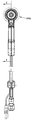
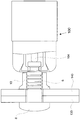
도 1은, 본 발명을 따르고 상기 록 볼트를 공작물속에 설치할 준비된 유압 작동식 설치 공구속에 삽입되는 록 볼트의 측단면도.
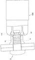
도 2는, 유지 요소가 연결상태를 가질 때 도 1의 영역(II)에 도시된 도 1의 공구가 설치된 상태 및 록 볼트를 상세하게 도시한 횡단면도.
도 2a 및 도 2b는, 본 발명을 따르는 선택적인 록 볼트들의 핀 테일을 도시한 부분 측면도.
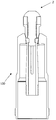
도 3a는, (명확한 이해를 위해 록 볼트가 도면에서 제거되고) 도 1의 설치 공구를 도시한 정면도 및선(I)을 따라 본 횡단면도.
도 3b는, 도 3a의 영역(IIIb)에 도시된 설치공구의 일부분을 도시한 세부도면.
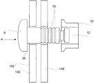
도 4는 본 발명을 따르고 록 볼트를 설치할 준비되고 도 3b의 선(IV-IV)을 따라 본 공구의 횡단면도.
도 5a 및 도 5b는, 명확한 이해를 위해 칼라의 유지요소를 제거하고 본 발명을 따르는 록 볼트 핀을 도시한 단순 측면도.
도 5c는, 본 발명을 따르는 록 볼트 칼라의 단순 측면도.
도 5d는, 완전한 스웨이징 성형의 표시수단을 포함하고 본 발명을 따르는 선택적인 록 볼트 칼라의 종 방향 단면도.
도 5e는 도 5d에 도시된 선택적인 록 볼트 칼라의 단부 도면.
도 5f는, 도 5d에 도시된 선택적인 록 볼트 칼라의 사시도.
도 6 내지 도 15는, 공구, 공작물 및 록 볼트가 단면 또는 부분 단면으로 표시되고 본 발명을 따르는 록 볼트의 설치단계를 도시한 도면.
도 16은, 본 발명을 따르는 록 볼트의 선택적 실시예의 설치 단계를 도시한 도면.
도 17은, 본 발명을 따르는 록 볼트의 또 다른 선택적 실시예를 설치하는 단계를 도시한 도면.
도 18a는, (명확한 이해를 위해 록 볼트 핀 및 공작물이 제거되고) 설치된 후에 도 5d 내지 도 5f의 선택적인 칼라를 도시한 단부도면.
도 18b는 도 18a의 선택적인 칼라의 측면도.
도 18c는 도 18a에 도시된 선택적인 칼라의 사시도.
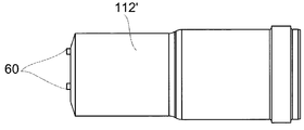
도 19a는, 본 발명을 따르는 선택적인 설치 공구 앤빌 부분을 도시한 단부 도면.
도 19b는 도 19a의 앤빌을 도시한 사시도.
도 19c는 도 19a의 앤빌을 도시한 측면도.BRIEF DESCRIPTION OF THE DRAWINGS Figure 1 is a side cross-sectional view of a lock bolt according to the present invention and inserted into a hydraulically actuated mounting tool prepared to install the lock bolt in a workpiece.
Fig. 2 is a cross-sectional view detailing the state of the tool of Fig. 1 and the lock bolt shown in area II of Fig. 1 when the holding element has a connected state. Fig.
Figures 2a and 2b are partial side views of a pin tail of selective lock bolts in accordance with the present invention.
Figure 3a is a cross-sectional view taken along a front view and a line (I) showing the installation tool of Figure 1 (with the lock bolts removed from the figure for clarity of understanding).
Figure 3b is a detail view showing a portion of the installation tool shown in region IIIb of Figure 3a;
Fig. 4 is a cross-sectional view of a tool prepared according to the present invention and viewed along line IV-IV of Fig. 3b prepared for mounting a lock bolt; Fig.
Figures 5A and 5B are simplified side views illustrating a lock bolt pin according to the present invention with a retaining element of the collar removed for a clear understanding;
Figure 5c is a simplified side view of a rock bolt collar according to the present invention.
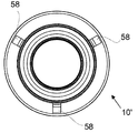
Figure 5d is a longitudinal cross-sectional view of an optional lock bolt collar incorporating a display means of complete swaging molding in accordance with the present invention.
Figure 5e is an end view of the optional lock bolt collar shown in Figure 5d.
Figure 5f is a perspective view of the optional lock bolt collar shown in Figure 5d.
Figs. 6 to 15 show the steps of mounting a lock bolt according to the present invention in which a tool, a work piece, and a lock bolt are shown in cross section or partial cross section.
Figure 16 shows the installation steps of an optional embodiment of a lock bolt according to the invention;
Fig. 17 shows the step of installing another alternative embodiment of a lock bolt according to the invention; Fig.
Figure 18a is an end view of the optional collar of Figures 5d-5f after being installed (with the lock bolt pin and workpiece removed for clarity);
Figure 18b is a side view of the optional collar of Figure 18a.
Figure 18c is a perspective view of the optional collar shown in Figure 18a;
19A is an end view showing an optional installation tool anvil portion according to the present invention.
FIG. 19B is a perspective view showing the anvil of FIG. 19A; FIG.
Figure 19c is a side view of the anvil of Figure 19a.
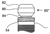
도면들을 참고할 때, 본 발명의 제1 특징을 따르는 록 볼트(2)는, 핀 테일(pin tail)(6) 및 핀 헤드(pin head)(8)를 포함한 핀(4) 및, (도 7의) 관통 구멍(12) 및 외부 표면(13)을 가진 플랜지(11)를 가지는 칼라(10)를 포함한다. 상기 핀 테일(6)은, 원형의 구속 그루브(18)들을 포함한 구속 부분(36), 상기 구속 부분(36) 및 핀 헤드(8) 사이에 위치한 제1 평면 부분(14), 상기 핀 헤드(8)로부터 떨어져 위치한 핀 테일(6)의 단부 면(22) 및 상기 구속 부분(36) 사이에 위치한 단일 풀 그루브(20)를 포함한다. 상기 구속 부분(36)은 도 5b에 도시된 것처럼 대직경(D)을 가지고 평행한 형상을 가지며 즉, 길이를 따라 일정한 대직경을 가진다. 상기 핀 테일(6)의 단부 면(22) 및 구속 그루브(18) 사이에 단부 부분(80)이 제공된다. 상기 단부 부분(80)은 평평하고 평행한 측부들을 가지며, 즉 길이를 따라 일정한 횡단면 영역을 가진다. 또한, 상기 단부 부분(80)은 상기 구속 부분(36)의 길이에 대하여 짧게 형성되고 상기 구속 부분(36)의 최대 직경보다 상대적으로 작은 최대 직경을 가진다. 예시적인 실시예에 의하면, D는 상기 구속 부분(36)의 최대 직경이고, G는 상기 풀 그루브(20)의 최소 직경이며(도면들에 도시된 실시예에서 상기 풀 그루브(20)의 최소 직경은 그루브 루트(groove root)(28)에 위치하고), T는 상기 단부 부분(80)의 최대 직경일 때, 다음 관계가 적용된다.Referring to the drawings, a
G = 0.675 D( 및 더 큰 값이 0.50D 내지 0.78D 범위내에 있다),G = 0.675 D (and larger values are in the range 0.50D to 0.78D),
T = 0.836 D( 및 더 큰 값이 0.7D 내지 1.0D 범위내에 있다).T = 0.836 D (and larger values are in the 0.7D to 1.0D range).
또한, L이 상기 풀 그루브(20)와 단부 부분(80)이 연장되는 핀 테일(6)의 전체 길이이고, N이 상기 단부 부분(80)이 연장되는 길이이며, M이 상기 풀 그루브(20)가 연장되는 길이일 때, 다음 관계가 적용된다.Wherein L is the total length of the pin tail (6) where the full groove (20) and end portion (80) extend, N is the length at which the end portion (80) extends, and M is the length of the full groove ) Is an extended length, the following relationship applies.
L = 0.936 D( 및 더 큰 값이 0.7D 내지 1.2D 범위내에 있다),L = 0.936 D (and larger values are in the 0.7D to 1.2D range),
M = 0.581 D( 및 더 큰 값이 0.3D 내지 0.7D 범위내에 있다),M = 0.581 D (and larger values are in the range of 0.3 D to 0.7 D)
N = 0.355 D( 및 더 큰 값이 0.26D 내지 0.5D 범위내에 있다).N = 0.355 D (and larger values are in the range of 0.26D to 0.5D).
4.8mm(3/16") 내지 25.4mm(1") 범위의 공칭 직경을 가진 핀들에 대하여 평면 부분(14)의 길이, 구속 부분(36)의 길이 및 상기 제1 평면 부분 길이와 상기 구속 부분 길이의 비율이 아래 표 1에 제공된다. 각 경우, 선택된 핀 길이는 공칭 핀 직경에 대하여 적어도 세 배인 총 결합 두께(joint thickness)를 고정할 수 있는 길이이다. 상기 구속 부분(36)의 길이에 대하여 상기 핀 테일 상의 제1 평면 부분(14)이 가지는 길이의 비율은 전형적으로 0.62 내지 1.27이다.The length of the
실시예에 의하면, 4.8mm(3/16") 내지 25.4mm(1") 범위의 공칭 직경을 가진 핀들에 대하여 상기 구속 부분(36)의 대직경(D), 구속 그루브(18)의 피치 및 상기 구속 그루브의 피치에 대한 구속 부분의 대직경의 비율이 아래 표 2에 제공된다. 상기 구속 그루브(18)의 피치는 전형적으로 0.40mm 내지 2.13mm 범위에 있고, 상기 구속 그루브(18)에 대해 상기 구속 부분(36)의 대직경(D)이 가지는 비율은 전형적으로 11.15 내지 12.01이다.According to the embodiment, the large diameter D of the restraining
단일 풀 그루브(20)는 제1 테이퍼 섹션(tepered section)(26), 제2 테이퍼 섹션(30)(상기 제2 테이퍼 섹션(30)은 상기 제1 테이퍼 섹션(28)보다 핀(6)의 테일 단부(22)와 더 근접하다), 및 제1 테이퍼 섹션(tepered section)(26) 및 제2 테이퍼 섹션(30) 사이에서 길이를 따라 일정한 횡단면 영역을 가진 그루브 루트(groove root)(28)를 포함하고, 상기 그루브 루트(28)는 핀 테일(6)의 축과 평행한다. The single
도 6 내지 도 15는, 설치 공구(100)를 이용하여 공작물 부재(130,140)들을 포함한 공작물이 가지는 구멍(120, 122)들속에 록 볼트(2)를 설치하여 공작물 부재(130,140)들을 서로 고정하기 위한 연속적인 단계들을 도시한다.6 to 15 show a state in which the
처음에 도 6에 도시된 것처럼, 헤드의 하측부(34)가 공작물의 후방 표면(152)과 접촉할 때까지 상기 핀(4)은 작업자가 손을 이용하여 공작물의 후방 측부(150)로부터 공작물 부재(130,140)의 구멍(120,122)속으로 삽입된다.The
상기 단계에서 핀 테일(6)의 일부분은 공작물의 전방 측부(16)로부터 돌출한다. 다음에, 도 7에 도시된 것처럼, 상기 칼라(10)는 사용자에 의해 공작물의 전방 측부(16)로부터 상기 핀 테일(6)의 돌출 단부에 조립된다. In this step, a portion of the
상기 칼라(10)가 상기 핀(4)위에 조립된 후에, 상기 칼라(10)는 상기 핀(4)위에서 초기 조립 상태로(연결된 위치에) 완전하게 유지된다. 상기 완전한 연결(positive engagement)은 유지 요소(retaining feature)(24)에 의해 형성된다. 도 1 및 도 2에 도시된 실시예에서, 상기 유지 요소(24)는 "가압 및 비틀기(push- and- twist)" 요소이고, 상기 핀 테일(6)위에 제공되고 얕은 축 방향 슬롯(56) 및, 상기 칼라(10)의 관통 구멍(12)위에 제공된 탭(tab)(52)을 포함한다. 상기 축 방향 슬롯(56)에 의해 상기 탭(52)은 상기 구속 부분(36)의 구속 그루브(18)에 대해 아래로 이동할 수 있다. 다음에 상기 칼라는 180°회전하여 상기 탭(52)은 상기 제1 구속 그루브(18)와 연결된다. 도 2에서, 상기 유지 요소(24)는 연결위치에 배열된다. 명확한 이해를 위해, 상기 유지 요소(24)는 설치 시퀀스에 관한 도면들에 도시되지 않는다.After the
상기 설치 공구가 다음 설치 단계를 위해 이용될 때까지 상기 유지 요소(24)는 상기 핀위에 칼라를 유지하기 위해 충분한 정도의 유지하중을 제공한다. 상기 설치 공구가 작동할 때, 상기 유지하중은 상기 설치 공구의 스웨이징 행정(swaging stroke)에 의해 극복되고 충분히 약해서 공작물속으로 설치되는 동안 상기 칼라(10)의 스웨이징 작용 및 시트 테이크업(sheet take-up)과정에 부정적인 영향을 주지 않는다.The retaining
다음에, 상기 록 볼트(2)는 상기 설치 공구(100)를 이용하여 공작물속으로 설치된다. 상기 설치 공구(100)는 노즈 피스(108)에 의해 둘러싸이는 ( 도 10내지 도 14에 도시된) 분할된 콜렛(split collet)(102)을 포함한다.Next, the lock bolts (2) are installed in the workpiece using the installation tool (100). The
(도 11b 내지 도 11c에서 가장 명확하게 도시된) 둥근 팁(rounded tip)(114)을 가진 (도 11 내지 도 14의) 돌출한 플런저(sprung plunger)(104)가 상기 설치 공구(100)내에 제공되고, 상기 플런저는 상기 록 볼트 핀의 단부면(22)내에 제공된 오목한 요홈(32)과 연결된다. 상기 핀 테일(6)이 상기 개방된 콜렛(102)내부로 들어갈 때 상기 플런저는 상기 록 볼트 핀의 단부 면(22)에 의해 가압된다. 상기 플런저(104)가 오목한 요홈(32)내에 연결되면, 상기 핀 테일이 상기 설치 공구(100)내에서 정확한 위치에 배열되고 즉 공구 축에 대해 허용될 수 없는 각도로 기울어지지 못하는 것이 보장된다. 상기 플런저(104)가 가압되어 작업자는 록 볼트(2)가 설치되기 시작한다. 핀 테일이 상기 공구 콜렛내에 부정확하게 배열되거나 핀 없이 공구가 불안하게 작동하여 작업자를 곤란하게 만드는 위험이 방지된다.A protruding plunger 104 (of Figures 11-14) with a rounded tip 114 (best seen in Figures 11b-11c) is mounted within the mounting
설치 공구(100)가 작동할 때 (도 1에 도시된 ) 유압 피스톤(106)은 상기 콜렛(102)에 대해 당김 하중(pulling force)을 증가시켜서 상기 풀 그루브(20)를 통해 핀 테일(6)에 대해 당김 하중을 작용시킨다. 상기 콜렛(102)이 상기 설치 공구(100)속으로 끌어당겨질 때 상기 노즈 피스(108)에 형성된 테이퍼 구조의 앤빌(anvil) 부분(112)에 의해 상기 콜렛(102)은 핀 테일(6)의 단부 근처에서 밀폐되고, 상기 콜렛(102)의 내부 립(lip)(110)은 제2 테이퍼 섹션(tapered section)(30)에 의해 제공된 접촉 표면에서 단일 풀 그루브(20)와 연결된다. 도면에 도시된 실시예에서, 상기 콜렛(102)의 내부 립(110)은 상기 풀 그루브(20)의 적어도 일부분과 짝을 이루는 형상을 가지고 즉, 상기 풀 그루브(20)의 제2 테이퍼 섹션(30) 및 그루브 루트(28)와 짝을 이루는 형상을 가져서 상기 콜렛(102)은 상기 제2 테이퍼 섹션(30) 및 그루브 루트(28)와 연결된다.The hydraulic piston 106 (shown in FIG. 1) when the
유압 피스톤(106)에 의해 상기 콜렛(102)에 가해지는 당김 하중은, 상기 풀 그루브(20)의 테이퍼 섹션(30)에 의해 제공된 접촉 표면을 통해 핀 테일(6)로 전달된다. 따라서, 또한, 상기 콜렛(102)이 상기 설치 공구(100)속으로 끌어 당겨질 때 상기 핀 테일(6)은 상기 설치 공구(100)를 향해 끌어 당겨진다.The pulling load applied to the
따라서, 상기 콜렛(102)이 상기 유압 피스톤(106)에 의해 상기 설치 공구(100)속으로 추가로 끌어 당겨질 때 상기 노즈 피스(108)의 앤빌 부분(112)은 칼라(10)와 접촉하고, 상기 칼라(10)는 상기 핀 헤드(8)를 향해 상기 앤빌 부분(112)에 의해 점진적으로 가압된다. 따라서 상기 공작물 부재(130,140)들은 서로 가압되어 이들사이에서 간격을 밀폐시키고 클램프 부하(clamp load)가 공작물에 가해진다. 상기 설치 공구(100)에 의해 가해지는 하중이 증가됨에 따라, 앤빌 부분(112)은 점차적으로 상기 핀 테일(6)의 구속 그루브(18) 속에 칼라(10)를 스웨이지 가공하고, 즉 상기 칼라(10)의 재료는 구속 그루브(18)속으로 가압된다.The
상기 설치 공구에 의해 가해지는 하중 따라서 상기 구속 그루브(18)에 대한 상기 칼라(10)의 스웨이징 작용은, 상기 하중이 미리 설정된 최대값에 도달할 때, 중지된다. 다음에 유압 피스톤(106)은 사전 작동 위치로 귀환하고, 상기 앤빌 부분(112)은 완전히 스웨이징 가공된 칼라(10)로부터 빼내어 진다. 상기 칼라(10)가 상기 핀 테일(6)에 대해 완전히 스웨이징 가공될 때, 상기 칼라는 상기 핀(4)에 단단히 고정되고 두 개의 부품들은 돌발적으로 분리될 수 없다.The load applied by the installation tool and therefore the swaging of the
상기 실시예에서, 상기 핀 테일(6)의 단부는 상기 록 볼트(2)가 공작물속에 설치되는 동안 파손되지 않는다. 그러나 도 16에 도시된 록 볼트(2')의 선택적인 실시예에 의하면, 단일 풀 그루브(20')가 제1 실시예의 풀 그루브(20) 보다 깊게 형성되기 때문에, 실치과정동안 상기 핀 테일(6')의 단부 부분(80')은 파손되며, 즉 제1 테이퍼 섹션(26') 및 제2 섹션(30')은 제1 부분의 제1 테이퍼 섹션 및 제2 섹션보다 깊다( 그 결과 그루브 루트(28')는 상대적으로 작은 직경을 가진다). 그러므로 상기 풀 그루브는 브레이커 그루브(breaker groove)로서 작동한다. 상기 실시예에서, 상기 설치 공구는, 상기 핀 테일이 상기 브레이커 그루브 풀 그루브(20)에서 파손될 때까지 상기 핀 테일(6')에 대해 당김 하중을 가한다. 상기 파손된 핀 부분(80')은 설치 사이클 이후에 설치 공구(100)로부터 배출된다. 상기 실시예에서, (도 16에 도시되지 않은) 콜렛(102)의 내부 립(110)은 상기 풀 그루브(20')의 내부립과 일치할 수 없지만, 공구의 하중은 아직까지 테이퍼 섹션(30')에 의해 제공된 접촉 표면을 통해 핀 테일(6')로 전달될 것이다.In this embodiment, the end of the
(도면에 도시되지 않은) 또 다른 실시예에 의하면, 접촉 표면은 풀 그루브의 선택적 요소, 예를 들어, 상기 핀 테일(6)의 축에 대해 90°인 접촉 표면을 제공하는 숄더(shoulder)에 의해 형성될 수 있다. According to another embodiment (not shown in the figures), the contact surface may be provided on a shoulder that provides an optional element of the full groove, for example a contact surface 90 [deg.] To the axis of the
선택적으로, 유지 요소(24)는 상기 핀 테일(6')의 섹션에 제공된 (도 2a의) 짧은 나선형 나사산(54) 및 상기 구속 부분 나사산이 연결되는 칼라(10)의 관통 구멍(12)에 제공되고 일치하는 짧은 나사산 또는 탭(tab) 또는 나선 부분을 포함할 수 있다. 상기 칼라(10)가 원형의 구속 그루브(18)속에 전체적으로 또는 대체로 스웨이징 성형됨에 따라 상기 칼라와 핀 테일(6)이 풀어질 위험은 제거된다.Alternatively, the retaining
또 다른 선택적 실시예에 의하면, 유지 요소(24)는 상기 칼라(10)의 관통 구멍(12) 또는 상기 핀 테일(6)의 구속 그루브(18)에 제공된 탄성중합체 재료의 비드(bead) 또는 링을 포함할 수 있다.According to another alternative embodiment, the retaining
선택적 실시예에 의하면, 서로 다른 프로파일 예를 들어, 단지 두 개의 테이퍼 섹션(26,30)들을 포함하며 평행한 그루브 루트(28), 즉 길이를 따라 일정한 횡단면 영역을 가진 그루브 루트를 포함하지 않는 풀 그루브가 제공될 수 있다. 선택적 형상을 가진 풀 그루브(20")의 예가 도 2a에 도시된다. 유사하게, 상기 설치 공구 콜렛(102)의 형상, 프로파일 및 구조는 또한 상이할 수 있다. 좀더 구체적으로 말하면, 상기 콜렛(102)의 내부 립(110)이 가지는 형상은 부분적으로 상기 풀 그루브(20)의 형상과 일치하지 못할 수 있다. 그러나 상기 풀 그루브의 테이퍼 섹션 및 상기 콜렛(102)의 내부 립(110)사이에 접촉이 아직도 형성된다.According to an alternative embodiment, different profiles may be used, for example, a
상기 핀 테일(6)의 단부 부분(80)은 평평하고 길이를 따라 일정한 횡단면 영역을 가진다. 그러나 상기 단부 부분(80)은, 선택적으로 두 개의 테이퍼 섹션(82,84)들 및 테이퍼 섹션(82,84)들사이에 위치하고 더 짧은 평평한 부분(86)을 포함한 단부 부분(80")과 같은 서로 다른 프로파일을 가질 수 있다.The end portion (80) of the pin tail (6) is flat and has a constant cross-sectional area along its length. However, the
도 2b에 도시된 선택적인 단부 부분과 같이, 핀 테일(6)은 상기 풀 그루브(20"')와 인접하고 단부 부분(80"을 향해 계단 형상 부분(stepped portion)(88)을 포함할 수 있다. 상기 계단 형상 부분(88)은 평평한 단부 부분(80"')보다 더 큰 횡단면 영역을 가진다. 제조과정에서 상기 계단 형상 부분은 상기 핀 테일(6)이 압연되는 동안 이동하는 재료에 의해 생산된다. 롤 성형(roll forming)하는 동안 금속 유동은 예를 들어, 기계식 절삭(machine- cut)가공되는 그루브보다 핀 테일(6)에 대해 더 우수한 강도를 제공한다.As with the optional end portion shown in Figure 2b, the
상기 계단 형상 부분(88)에 의해, 상기 콜렛(102)의 내부 립(110)과 접촉하기 위한 추가적인 표면(90)이 효과적으로 제공되어, 설치 공구가 접촉하는 표면의 횡단면 영역이 더 커짐에 따라 설치 작업시 핀 테일의 국소 보강작용이 형성된다.The stepped
상기 실시예에 의하면 설치 공구에 제공되는 플런저와 연결되는 록 볼트의 핀테일의 단부 면에 오목부(dimple)가 구성되지만, 도 17에 도시된 선택적 실시예에 의하면 오목부 및 플런저가 구성되지 않는다. 도 17에 도시되고 록 볼트와 연결된 공구에 의하면, 상기 록 볼트의 종 방향 축이 공구의 종 방향과 정렬되지 않는다. 정렬되지 않은 각위치에도 불구하고, 단일 풀 그루브(20)가 가지는 깊이 때문에, 상기 공구 및 록 볼트는 연결된 상태를 유지한다. 공구에 대해 록 볼트(2)가 형성하는 정렬된 각위치는 설치 공구(100)의 작동에 의해 수정된다.According to this embodiment, a dimple is formed at the end face of the pin tail of the lock bolt connected to the plunger provided in the installation tool, but according to the alternative embodiment shown in Fig. 17, the recess and the plunger are not constructed . According to the tool shown in Fig. 17 and connected to the lock bolt, the longitudinal axis of the lock bolt is not aligned with the longitudinal direction of the tool. Because of the depth of the single
본 발명을 따르는 록 볼트의 선택적 실시예는 완전한 스웨이징 성형의 표시수단을 포함한다. 도 5d 내지 도 5f의 예에서, 완전한 스웨이징 성형의 표시수단은 칼라(10')의 플랜지(11')의 외부 표면(13')에 제공된 돌출부(58)를 포함한다. 록 볼트가 설치될 때 설치 공구(100)의 앤빌 부분(112)이 상기 돌출부(58)에 도달하면, 돌출부(58)는 적어도 부분적으로 변형된다.An optional embodiment of a lock bolt according to the present invention comprises a display means of complete swaging. In the example of Figures 5d to 5f, the display means of complete swaging comprises a
상기 칼라(10')가 상기 핀 테일(6)상에 완전히 스웨이징 성형되도록 상기 앤빌 부분(112)이 한점에 도달한 후에야 상기 돌출부(58)들은 가압된다. 따라서, 상기 설가 상기 록 볼트로부터 빠져나올 때, 작업자는 상기 돌출부(58)들이 적어도 부분적으로 가압된 것을 점검할 수 있고 이에 따라 상기 핀 테일(6)에 상기 칼라(10')가 완전히 스웨이징 성형된 것을 확인할 수 있다. 도 5d 내지 도 5f에 도시된 칼라가 설치된 후에 상태가 도 18a 내지 도 18c에 도시된다( 상기 록 볼트가 설치되는 공작물 및 록 볼트핀이 명확한 이해를 위해 제거된다). 돌출부(58)들은 상기 앤빌 부분(112)에 의해 부분적으로 변형된다. 세 개의 돌출부(58)들이 칼라(10') 주위에서 동일한 거리를 두고 제공됨에 따라, 작업자는 상기 칼라(10')가 칼라(10')의 전체 주변부 주위에서 상기 핀 테일(6)상에 완전히 스웨이징 성형된 것을 확인할 수 있다.The
도 19a 내지 도 19c에 도시된 선택적 실시예에 의하면, 완전한 스웨이징 성형의 표시수단은 공구의 상기 앤빌 부분(112')의 단부 면(59)에 제공된 한 개이상의 돌출부(60)들을 포함하고, 상기 칼라(10)가 상기 핀 테일(6)상에 완전히 스웨이징 성형될 때 돌출부(60)들이 상기 칼라(10)의 플랜지(11)의 외부 표면(13)속으로 가압되어 상기 성형 공궈(100)가 상기 록 볼트로부터 분리될 때 상기 칼라(10)가 상기 핀 테일(6)위에 완전히 스웨이징 성형된 것을 표시하도록 상기 돌출부(60)들이 배열된다. 동일한 거리를 두고 이격된 세 개의 돌출부(60)들이 제공되기 때문에, 작업자는 상기 칼라(10)의 전체 주변부 주위에서 상기 칼라(10)가 상기 핀 테일(6)상에 완전히 스웨이징 성형된 것을 확인할 수 있다.19A-19C, the display means of complete swaging comprises one or
10.....칼라,
20.....풀 그루브.10 ..... color,
20 ..... full groove.
Claims (34)
상기 핀은 핀 헤드 및 공작물 부재내부의 정렬된 구멍들을 통해 삽입되는 핀 테일을 포함하고,
상기 핀 테일은 구속 그루브들을 포함한 구속 부분 및 단지 한 개의 풀 그루브를 포함하며, 상기 풀 그루브는 제1 테이퍼 섹션, 제2 테이퍼 섹션 및 상기 제1 테이퍼 섹션과 제2 테이퍼 섹션사이에 위치한 평평한 부분을 포함하고, 상기 풀 그루브는 상기 구속 부분 및 상기 핀 헤드로부터 떨어진 핀 테일의 단부면사이에 제공되며, 상기 풀 그루브 및 단부 면사이에 제공된 단부 부분을 포함하고,
상기 칼라는 상기 구속 그루브위에 끼워 맞춤되고 상기 구속 그루브위에 스웨이징 성형되며, 상기 풀 그루브의 상기 테이퍼 섹션들 중 한 개가 접촉 표면을 제공하는 것을 특징으로 하는 록 볼트.
A lock bolt fixture comprising a collar and a pin,
The pin including a pin head and a pin tail inserted through aligned holes in the workpiece member,
The pin tail comprising a restraint portion including restraint grooves and only one full groove, the full groove including a first taper section, a second taper section, and a flat portion located between the first taper section and the second taper section Wherein the full groove is provided between the constraining portion and the end face of the pin tail remote from the pin head and includes an end portion provided between the full groove and the end face,
Wherein the collar is fitted over the constraining groove and is swaged on the constraining groove, wherein one of the tapered sections of the full groove provides a contact surface.
The lock bolt according to claim 1, wherein a length of the full groove coupled with the end portion is shorter than a length of the restricting portion and has a maximum diameter smaller than a maximum diameter of the restricting portion.
The lock bolt according to claim 1, wherein the restricting portion has a predetermined large diameter along its length.
The lock bolt according to claim 1, wherein the restricting groove has a circular shape.
The rock bolt according to claim 1, wherein the ratio of the minimum diameter of the full groove to the maximum diameter of the restricting portion is in the range of 0.50 to 0.78.
The lock bolt according to claim 1, wherein the ratio of the maximum diameter of the end portion to the maximum diameter of the restraining portion is in the range of 0.7 to 1.0.
The lock bolt according to claim 1, wherein the ratio of the end portion to the maximum diameter of the restraint portion to the total length of the pin tail extending the restricting groove is in the range of 0.7 to 1.2.
The lock bolt according to claim 1, wherein the ratio of the length of the pin tail extending from the full groove to the maximum diameter of the restraining portion is in the range of 0.3 to 0.7.
2. The lock bolt according to claim 1, wherein the ratio of the length of the pin tail extending from the end portion to the maximum diameter of the restricting portion is in the range of 0.26 to 0.5.
The rock bolt of claim 1, wherein the flat portion of the full groove has a constant cross-sectional area over its length.
2. The lock bolt of claim 1, further comprising a retaining element for retaining the collar at an initial assembly position of the pinion.
12. The apparatus of claim 11, wherein the retaining element comprises at least one thread, spiral or tab formed in, and coinciding with, the through-hole of the spiral thread and collar provided in the section of the constraining portion adjacent the full groove, And a helical thread is connected to the through hole.
12. The apparatus of claim 11, wherein the retaining element is provided on the pin tail and includes a shallow flat or axial slot, wherein a tab provided in the through hole of the collar is configured to engage the constraining Quot; and " twist "movement while moving toward the first restraining groove of the portion.
12. The lock bolt of claim 11, wherein the retaining element comprises a bead or ring of elastomeric material provided in the through hole of the collar or the restraining groove of the pin tail.
The method of claim 1, wherein the pin tail further comprises a step forming portion adjacent the full groove between the full groove and the end face of the pin tail remote from the pin head, And a large cross-sectional area.
16. A pin according to any one of the preceding claims, further comprising a flat portion between said pin head and said restraining portion, said pin having a length which is capable of fixing a total connection thickness of at least three times the nominal pin diameter Wherein the ratio of the length of the flat portion to the length of the restraint portion with respect to the length of the locking portion is in the range of 0.62 to 1.27.
The lock bolt according to claim 1, further comprising indicating means for complete swaging.
18. A method as claimed in claim 17, wherein the indicating means of complete swaging comprises at least one protrusion provided on an outer surface of the collar flange, the protrusions being adapted to be at least partially deformed or broken when a load of the anvil portion of the mounting tool acts And the lock bolt.
An installation tool including a lock bolt according to claim 1 for installing a lock bolt and a collet surrounded by a nose piece, said nose piece having an anvil portion of a tapered configuration.
20. The apparatus of claim 19, wherein the mounting tool further comprises a plunger that is pressurizable, and wherein the mounting tool fails to operate when the plunger is not pressed.
21. The apparatus of claim 20, wherein the plunger has a rounded tip connectable with a concave element formed in an end face of the rock bolt pin tail.
20. The apparatus of claim 19, wherein a portion of the collet has a shape that mates with at least a portion of the shape of the full groove.
20. The device of claim 19, wherein the tool further comprises at least one protrusion formed in the anvil portion, the at least one protrusion configured to deform an outer surface of the flange of the collar when the lock bolt is installed Characterized in that.
핀 헤드의 하측부가 상기 공작물의 후방 측부와 접촉하고 상기 핀 테일이 상기 공작물의 전방 측부로부터 부분적으로 돌출할 때까지 공작물의 후방 측부로부터 공작물의 구멍속으로 핀을 삽입하는 단계,
상기 공작물의 전방 측부로부터 상기 핀 테일의 돌출 단부상에 칼라를 끼워 맞추는 단계,
상기 설치 공구를 작동시키고 상기 콜렛에 당김 하중을 가하여, 상기 노즈 피스의 앤빌 섹션에 의해 상기 콜렛이 밀폐되고 따라서 상기 풀 그루브의 접촉표면과 연결되며, 상기 풀 그루브에 의해 상기 핀 테일에 당김 하중이 가해지는 단계,
다음에 상기 칼라는 상기 공작물 부재들을 향해 가압되고 상기 공작물 부재들을 서로 모으는 단계, 및
다음에 상기 노즈 피스의 공구 앤빌 섹션에 의해 하중이 상기 칼라에 가해져서, 상기 핀 테일의 구속 그루브속에 상기 칼라가 점차로 스웨이징 성형되는 단계를 포함하는 것을 특징으로 하는 방법.
There is provided a method for fixing workpiece members to each other by installing a lock bolt of the first aspect in a workpiece including a workpiece having a hole by using an installation tool including a collet surrounded by a nose piece having an inlet piston and an anvil section with a tapered structure ,
Inserting the pin into the hole of the workpiece from the back side of the workpiece until the lower side of the pin head contacts the back side of the workpiece and the pin tail projects partially from the front side of the workpiece,
Fitting the collar onto the projecting end of the pin tail from the front side of the workpiece,
The collet is sealed by an anvil section of the nose piece and thus is connected to the contact surface of the full groove, and a pulling load is applied to the pin tail by the pull groove The step being applied,
The collar is then pressed against the workpiece members and collecting the workpiece members together,
And then a load is applied to the collar by means of a tool and anvil section of the nose piece such that the collar gradually forms a swaging in the restraining groove of the pin tail.
25. The method of claim 24, wherein when the load applied by the tool reaches a predetermined maximum value, the load is interrupted and the anvil portion is withdrawn from the collar.
25. The method of claim 24, wherein the load applied by the tool is interrupted when a portion of the pin tail breaks the breaker groove formed by the full groove.
25. The assembly of claim 24, wherein the lock bolt further comprises a retaining element such that after the collar is fitted to the pin and before the mounting tool is used to install the lock bolt in the workpiece, And is held on the pin.
25. The method of claim 24, wherein the outer surface of the flange of the collar has one or more protrusions, wherein after the collar is fully swaged on the pin tiles during installation of the lock bolts, ≪ / RTI > is deformed or broken.
25. The method of claim 24, wherein the tool anvil has one or more protrusions, wherein after the collar has been completely swaged on the pin tiles during installation of the lock bolts, the protrusions have a portion of the outer surface of the flange of the collar . ≪ / RTI >
25. The method of claim 24, further comprising rolling the pin, wherein the material of the pin tail moves to form a stepped portion, the stepped portion having a larger cross-sectional area than the end portion ≪ / RTI >
상기 공구는 유압 피스톤 및 콜렛을 포함하고, 상기 공구가 작동할 때 상기 콜렛은 개방 위치로부터 밀폐위치로 이동하며 상기 유압 피스톤에 의해 상기 공구속으로 끌어 당겨지며, 상기 콜렛은 록 볼트 주위에 밀폐되도록 구성되어 상기 록 볼트의 풀 그루브가 내부 립과 연결되어 록 볼트는 상기 공구속으로 끌어 당겨지는 것을 특징으로 하는 공구.
1. A tool for installing the lock bolt of claim 1 in a workpiece including workpiece members having holes,
Wherein the tool includes a hydraulic piston and a collet, wherein when the tool is actuated, the collet moves from an open position to a closed position and is drawn into the tool by the hydraulic piston, Wherein the full groove of the lock bolt is connected to the inner lip so that the lock bolt is pulled into the tool.
32. The method of claim 31, wherein the surface of the stepped portion provided adjacent the full groove between the full groove and the end face of the pin tail remote from the pin head is connected to the inner lip, And a larger cross-sectional area.
DETAILED DESCRIPTION OF THE PREFERRED EMBODIMENTS The lock bolts shown in the attached drawings and described herein.
BRIEF DESCRIPTION OF THE DRAWINGS Fig.
Applications Claiming Priority (2)
| Application Number | Priority Date | Filing Date | Title |
|---|---|---|---|
| GB1315989.2A GB2506525B (en) | 2012-09-13 | 2013-09-09 | Lockbolt |
| PCT/IB2014/065857 WO2015033330A1 (en) | 2013-09-09 | 2014-11-06 | Lockbolt |
Publications (2)
| Publication Number | Publication Date |
|---|---|
| KR20170067157A true KR20170067157A (en) | 2017-06-15 |
| KR102030889B1 KR102030889B1 (en) | 2019-10-10 |
Family
ID=51897405
Family Applications (1)
| Application Number | Title | Priority Date | Filing Date |
|---|---|---|---|
| KR1020167004833A KR102030889B1 (en) | 2013-09-09 | 2014-11-06 | Lockbolt |
Country Status (6)
| Country | Link |
|---|---|
| US (1) | US10393164B2 (en) |
| EP (1) | EP3044466B1 (en) |
| JP (1) | JP6364492B2 (en) |
| KR (1) | KR102030889B1 (en) |
| CN (1) | CN105765241B (en) |
| WO (1) | WO2015033330A1 (en) |
Cited By (2)
| Publication number | Priority date | Publication date | Assignee | Title |
|---|---|---|---|---|
| KR102161988B1 (en) * | 2019-09-17 | 2020-10-06 | 주식회사 가우리안 | Press-in nut-bolt assembly and construction method of steel material-concrete complex structure using it |
| WO2021099814A1 (en) * | 2019-11-22 | 2021-05-27 | Howmet Aerospace Inc. | Fastening collar installation apparatus and methods of installing a fastener system |
Families Citing this family (10)
| Publication number | Priority date | Publication date | Assignee | Title |
|---|---|---|---|---|
| US10233936B2 (en) | 2016-03-25 | 2019-03-19 | Garrett Transportation I Inc. | Turbocharger compressor wheel assembly |
| US10502660B2 (en) * | 2016-03-25 | 2019-12-10 | Garrett Transportation I Inc. | Turbocharger compressor wheel assembly |
| US10677257B2 (en) | 2016-03-25 | 2020-06-09 | Garrett Transportation I Inc. | Turbocharger compressor wheel assembly |
| US10483901B2 (en) | 2017-07-10 | 2019-11-19 | Newfrey Llc | System and method for installation and verification of fasteners |
| US11033952B2 (en) * | 2018-09-24 | 2021-06-15 | The Boeing Company | Offset collar delivery for swage tools |
| BR112021013585A2 (en) * | 2019-02-07 | 2021-09-28 | Howmet Aerospace Inc. | BLIND FIXER AND INSTALLATION METHOD |
| DE102019208099A1 (en) * | 2019-06-04 | 2020-12-10 | Vitesco Technologies Germany Gmbh | Rotor for an electrical machine, method for producing a rotor and electrical machine with a rotor |
| CA3153113A1 (en) | 2019-09-17 | 2021-03-25 | Gaurian Corporation | Press-fit nut for assembly, press-fit nut-bolt assembly, and method of constructing steel-concrete composite structure using same |
| CN110762100A (en) * | 2019-11-28 | 2020-02-07 | 眉山中车紧固件科技有限公司 | Pull rivet for fastening and connecting conductive materials |
| EP4158210A4 (en) * | 2020-05-27 | 2024-07-10 | Howmet Aerospace Inc | Multi-piece fastener comprising a tapered threaded portion and method of fastening |
Citations (19)
| Publication number | Priority date | Publication date | Assignee | Title |
|---|---|---|---|---|
| US1629925A (en) * | 1924-08-29 | 1927-05-24 | Moore Fred Cushing | Plate-bolting-up machine |
| GB858882A (en) * | 1958-02-14 | 1961-01-18 | Huck Mfg Co | Improvements relating to pins for two-part rivet fasteners |
| US3091982A (en) * | 1959-02-17 | 1963-06-04 | Olympic Screw & Rivet Corp | Method of setting lock bolts |
| US3295404A (en) * | 1965-06-24 | 1967-01-03 | Dykes M Baker | Collar for huck fastener |
| US3996784A (en) * | 1974-10-21 | 1976-12-14 | The Boeing Company | Single operation-triple cycle lockbolt setting device and system |
| US4254809A (en) * | 1978-09-11 | 1981-03-10 | Hi Shear Corporation | Two-piece rivet |
| US4299519A (en) * | 1979-01-10 | 1981-11-10 | Huck Manufacturing Company | Two piece fastener and installation tool |
| WO1987000891A1 (en) * | 1985-08-01 | 1987-02-12 | Huck Manufacturing Company | Fit-up fastener with flexible tab-like retaining structure and method of making same |
| US4813834A (en) * | 1985-08-01 | 1989-03-21 | Huck Manufacturing Company | Fit-up fastener with flexible tab-like retaining structure and method of making same |
| US4995777A (en) * | 1990-04-09 | 1991-02-26 | Vsi Corporation | Fastener with self-retaining collar |
| US5315755A (en) * | 1989-05-31 | 1994-05-31 | Huck Patents, Inc. | Fastener system including a swage fastener and a tool for installing same |
| US6213699B1 (en) * | 1999-09-10 | 2001-04-10 | Huck International, Inc. | Filling rivet with high pin lock |
| US20050276658A1 (en) * | 2004-06-09 | 2005-12-15 | Fred Silva | Quick release shackle pin system |
| US20080170926A1 (en) * | 2007-01-16 | 2008-07-17 | Taylor Harry E | Blind rivet |
| US20090047060A1 (en) * | 2006-08-10 | 2009-02-19 | Turnasure, Llc | Securing Mechanisms for Components of a Load Indicating Fastener |
| JP2011017443A (en) * | 2010-08-27 | 2011-01-27 | Huck Internatl Inc | Fastener |
| CA2788797A1 (en) * | 2011-09-14 | 2013-03-14 | Profil Verbindungstechnik Gmbh & Co. Kg | Rivet element |
| US20130202382A1 (en) * | 2012-02-02 | 2013-08-08 | Alcoa Inc. | Swage indicating collar |
| WO2014041328A1 (en) * | 2012-09-13 | 2014-03-20 | Infastech Intellectual Properties Pte Ltd | Lockbolt |
Family Cites Families (9)
| Publication number | Priority date | Publication date | Assignee | Title |
|---|---|---|---|---|
| CA1122830A (en) | 1979-01-10 | 1982-05-04 | Robert J. Corbett | Two piece fastener and installation tool |
| US4324518A (en) * | 1979-07-13 | 1982-04-13 | Huck Manufacturing Company | Dish compensating flush head fastener |
| JP2672190B2 (en) * | 1989-05-31 | 1997-11-05 | ハック マニュファクチュアリング カンパニー | Fastening method including swage fasteners and tools to attach them |
| US5213460A (en) * | 1991-05-24 | 1993-05-25 | Huck International, Inc. | High strength blind bolt with uniform high clamp over an extended grip range |
| JPH0925922A (en) | 1995-07-12 | 1997-01-28 | Aoyama Seisakusho:Kk | Bolt and method of tightening by using this bolt |
| GB2344864A (en) * | 1998-12-17 | 2000-06-21 | Textron Fastening Syst Ltd | Blind fastener |
| US6702684B2 (en) * | 2002-04-05 | 2004-03-09 | Huck International, Inc. | Method of designing and manufacturing a swage type fastener |
| CN101912941B (en) * | 2006-11-03 | 2012-05-02 | 胡克国际公司 | Fastening piece |
| JP5602205B2 (en) * | 2012-10-29 | 2014-10-08 | ハック インターナショナル,インコーポレイテッド | Fastener |
-
2014
- 2014-11-06 US US14/914,908 patent/US10393164B2/en active Active
- 2014-11-06 WO PCT/IB2014/065857 patent/WO2015033330A1/en active Application Filing
- 2014-11-06 EP EP14796911.7A patent/EP3044466B1/en active Active
- 2014-11-06 KR KR1020167004833A patent/KR102030889B1/en active IP Right Grant
- 2014-11-06 JP JP2016539677A patent/JP6364492B2/en active Active
- 2014-11-06 CN CN201480049423.0A patent/CN105765241B/en active Active
Patent Citations (19)
| Publication number | Priority date | Publication date | Assignee | Title |
|---|---|---|---|---|
| US1629925A (en) * | 1924-08-29 | 1927-05-24 | Moore Fred Cushing | Plate-bolting-up machine |
| GB858882A (en) * | 1958-02-14 | 1961-01-18 | Huck Mfg Co | Improvements relating to pins for two-part rivet fasteners |
| US3091982A (en) * | 1959-02-17 | 1963-06-04 | Olympic Screw & Rivet Corp | Method of setting lock bolts |
| US3295404A (en) * | 1965-06-24 | 1967-01-03 | Dykes M Baker | Collar for huck fastener |
| US3996784A (en) * | 1974-10-21 | 1976-12-14 | The Boeing Company | Single operation-triple cycle lockbolt setting device and system |
| US4254809A (en) * | 1978-09-11 | 1981-03-10 | Hi Shear Corporation | Two-piece rivet |
| US4299519A (en) * | 1979-01-10 | 1981-11-10 | Huck Manufacturing Company | Two piece fastener and installation tool |
| US4813834A (en) * | 1985-08-01 | 1989-03-21 | Huck Manufacturing Company | Fit-up fastener with flexible tab-like retaining structure and method of making same |
| WO1987000891A1 (en) * | 1985-08-01 | 1987-02-12 | Huck Manufacturing Company | Fit-up fastener with flexible tab-like retaining structure and method of making same |
| US5315755A (en) * | 1989-05-31 | 1994-05-31 | Huck Patents, Inc. | Fastener system including a swage fastener and a tool for installing same |
| US4995777A (en) * | 1990-04-09 | 1991-02-26 | Vsi Corporation | Fastener with self-retaining collar |
| US6213699B1 (en) * | 1999-09-10 | 2001-04-10 | Huck International, Inc. | Filling rivet with high pin lock |
| US20050276658A1 (en) * | 2004-06-09 | 2005-12-15 | Fred Silva | Quick release shackle pin system |
| US20090047060A1 (en) * | 2006-08-10 | 2009-02-19 | Turnasure, Llc | Securing Mechanisms for Components of a Load Indicating Fastener |
| US20080170926A1 (en) * | 2007-01-16 | 2008-07-17 | Taylor Harry E | Blind rivet |
| JP2011017443A (en) * | 2010-08-27 | 2011-01-27 | Huck Internatl Inc | Fastener |
| CA2788797A1 (en) * | 2011-09-14 | 2013-03-14 | Profil Verbindungstechnik Gmbh & Co. Kg | Rivet element |
| US20130202382A1 (en) * | 2012-02-02 | 2013-08-08 | Alcoa Inc. | Swage indicating collar |
| WO2014041328A1 (en) * | 2012-09-13 | 2014-03-20 | Infastech Intellectual Properties Pte Ltd | Lockbolt |
Cited By (4)
| Publication number | Priority date | Publication date | Assignee | Title |
|---|---|---|---|---|
| KR102161988B1 (en) * | 2019-09-17 | 2020-10-06 | 주식회사 가우리안 | Press-in nut-bolt assembly and construction method of steel material-concrete complex structure using it |
| WO2021099814A1 (en) * | 2019-11-22 | 2021-05-27 | Howmet Aerospace Inc. | Fastening collar installation apparatus and methods of installing a fastener system |
| EP4045801A4 (en) * | 2019-11-22 | 2022-11-09 | Howmet Aerospace Inc. | Fastening collar installation apparatus and methods of installing a fastener system |
| US12083581B2 (en) | 2019-11-22 | 2024-09-10 | Howmet Aerospace Inc. | Fastening collar installation apparatus and methods of installing a fastener system |
Also Published As
| Publication number | Publication date |
|---|---|
| KR102030889B1 (en) | 2019-10-10 |
| US10393164B2 (en) | 2019-08-27 |
| CN105765241B (en) | 2018-10-12 |
| JP6364492B2 (en) | 2018-07-25 |
| EP3044466B1 (en) | 2017-11-01 |
| US20160215808A1 (en) | 2016-07-28 |
| JP2016535221A (en) | 2016-11-10 |
| WO2015033330A1 (en) | 2015-03-12 |
| EP3044466A1 (en) | 2016-07-20 |
| CN105765241A (en) | 2016-07-13 |
Similar Documents
| Publication | Publication Date | Title |
|---|---|---|
| KR20170067157A (en) | Lockbolt | |
| JP6499677B2 (en) | Rock bolt | |
| CA2778104C (en) | Clinch pin fastener | |
| US8616039B2 (en) | Method of manufacturing a clinch pin fastener | |
| JP5300027B2 (en) | Fixing method of pierce nut | |
| CA2843732A1 (en) | Miniature tack pins | |
| EP3334944B1 (en) | Blind fastener | |
| CN107105612B (en) | Appliance coupling device and machine provided with such a device | |
| US8029220B2 (en) | Blind rivet assembly | |
| CN108474402A (en) | Thin slice clinching fasteners | |
| KR20240143920A (en) | Fastener, fastening assembly and method of installing a fastener | |
| NZ788937A (en) | A Coupling Device, Associated Parts and a Method of Use Thereof |
Legal Events
| Date | Code | Title | Description |
|---|---|---|---|
| A201 | Request for examination | ||
| A302 | Request for accelerated examination | ||
| E902 | Notification of reason for refusal | ||
| E701 | Decision to grant or registration of patent right | ||
| GRNT | Written decision to grant |