KR20170066726A - Electric brake system - Google Patents
Electric brake system Download PDFInfo
- Publication number
- KR20170066726A KR20170066726A KR1020150172065A KR20150172065A KR20170066726A KR 20170066726 A KR20170066726 A KR 20170066726A KR 1020150172065 A KR1020150172065 A KR 1020150172065A KR 20150172065 A KR20150172065 A KR 20150172065A KR 20170066726 A KR20170066726 A KR 20170066726A
- Authority
- KR
- South Korea
- Prior art keywords
- hydraulic
- pressure
- hydraulic oil
- pressure chamber
- oil
- Prior art date
Links
Images


Classifications
-
- B—PERFORMING OPERATIONS; TRANSPORTING
- B60—VEHICLES IN GENERAL
- B60T—VEHICLE BRAKE CONTROL SYSTEMS OR PARTS THEREOF; BRAKE CONTROL SYSTEMS OR PARTS THEREOF, IN GENERAL; ARRANGEMENT OF BRAKING ELEMENTS ON VEHICLES IN GENERAL; PORTABLE DEVICES FOR PREVENTING UNWANTED MOVEMENT OF VEHICLES; VEHICLE MODIFICATIONS TO FACILITATE COOLING OF BRAKES
- B60T13/00—Transmitting braking action from initiating means to ultimate brake actuator with power assistance or drive; Brake systems incorporating such transmitting means, e.g. air-pressure brake systems
- B60T13/10—Transmitting braking action from initiating means to ultimate brake actuator with power assistance or drive; Brake systems incorporating such transmitting means, e.g. air-pressure brake systems with fluid assistance, drive, or release
- B60T13/66—Electrical control in fluid-pressure brake systems
- B60T13/68—Electrical control in fluid-pressure brake systems by electrically-controlled valves
- B60T13/686—Electrical control in fluid-pressure brake systems by electrically-controlled valves in hydraulic systems or parts thereof
-
- B—PERFORMING OPERATIONS; TRANSPORTING
- B60—VEHICLES IN GENERAL
- B60T—VEHICLE BRAKE CONTROL SYSTEMS OR PARTS THEREOF; BRAKE CONTROL SYSTEMS OR PARTS THEREOF, IN GENERAL; ARRANGEMENT OF BRAKING ELEMENTS ON VEHICLES IN GENERAL; PORTABLE DEVICES FOR PREVENTING UNWANTED MOVEMENT OF VEHICLES; VEHICLE MODIFICATIONS TO FACILITATE COOLING OF BRAKES
- B60T8/00—Arrangements for adjusting wheel-braking force to meet varying vehicular or ground-surface conditions, e.g. limiting or varying distribution of braking force
- B60T8/32—Arrangements for adjusting wheel-braking force to meet varying vehicular or ground-surface conditions, e.g. limiting or varying distribution of braking force responsive to a speed condition, e.g. acceleration or deceleration
- B60T8/321—Arrangements for adjusting wheel-braking force to meet varying vehicular or ground-surface conditions, e.g. limiting or varying distribution of braking force responsive to a speed condition, e.g. acceleration or deceleration deceleration
- B60T8/3255—Systems in which the braking action is dependent on brake pedal data
-
- B—PERFORMING OPERATIONS; TRANSPORTING
- B60—VEHICLES IN GENERAL
- B60T—VEHICLE BRAKE CONTROL SYSTEMS OR PARTS THEREOF; BRAKE CONTROL SYSTEMS OR PARTS THEREOF, IN GENERAL; ARRANGEMENT OF BRAKING ELEMENTS ON VEHICLES IN GENERAL; PORTABLE DEVICES FOR PREVENTING UNWANTED MOVEMENT OF VEHICLES; VEHICLE MODIFICATIONS TO FACILITATE COOLING OF BRAKES
- B60T13/00—Transmitting braking action from initiating means to ultimate brake actuator with power assistance or drive; Brake systems incorporating such transmitting means, e.g. air-pressure brake systems
- B60T13/10—Transmitting braking action from initiating means to ultimate brake actuator with power assistance or drive; Brake systems incorporating such transmitting means, e.g. air-pressure brake systems with fluid assistance, drive, or release
- B60T13/12—Transmitting braking action from initiating means to ultimate brake actuator with power assistance or drive; Brake systems incorporating such transmitting means, e.g. air-pressure brake systems with fluid assistance, drive, or release the fluid being liquid
- B60T13/14—Transmitting braking action from initiating means to ultimate brake actuator with power assistance or drive; Brake systems incorporating such transmitting means, e.g. air-pressure brake systems with fluid assistance, drive, or release the fluid being liquid using accumulators or reservoirs fed by pumps
- B60T13/142—Systems with master cylinder
- B60T13/145—Master cylinder integrated or hydraulically coupled with booster
- B60T13/146—Part of the system directly actuated by booster pressure
-
- B—PERFORMING OPERATIONS; TRANSPORTING
- B60—VEHICLES IN GENERAL
- B60T—VEHICLE BRAKE CONTROL SYSTEMS OR PARTS THEREOF; BRAKE CONTROL SYSTEMS OR PARTS THEREOF, IN GENERAL; ARRANGEMENT OF BRAKING ELEMENTS ON VEHICLES IN GENERAL; PORTABLE DEVICES FOR PREVENTING UNWANTED MOVEMENT OF VEHICLES; VEHICLE MODIFICATIONS TO FACILITATE COOLING OF BRAKES
- B60T13/00—Transmitting braking action from initiating means to ultimate brake actuator with power assistance or drive; Brake systems incorporating such transmitting means, e.g. air-pressure brake systems
- B60T13/10—Transmitting braking action from initiating means to ultimate brake actuator with power assistance or drive; Brake systems incorporating such transmitting means, e.g. air-pressure brake systems with fluid assistance, drive, or release
- B60T13/66—Electrical control in fluid-pressure brake systems
- B60T13/662—Electrical control in fluid-pressure brake systems characterised by specified functions of the control system components
-
- B—PERFORMING OPERATIONS; TRANSPORTING
- B60—VEHICLES IN GENERAL
- B60T—VEHICLE BRAKE CONTROL SYSTEMS OR PARTS THEREOF; BRAKE CONTROL SYSTEMS OR PARTS THEREOF, IN GENERAL; ARRANGEMENT OF BRAKING ELEMENTS ON VEHICLES IN GENERAL; PORTABLE DEVICES FOR PREVENTING UNWANTED MOVEMENT OF VEHICLES; VEHICLE MODIFICATIONS TO FACILITATE COOLING OF BRAKES
- B60T13/00—Transmitting braking action from initiating means to ultimate brake actuator with power assistance or drive; Brake systems incorporating such transmitting means, e.g. air-pressure brake systems
- B60T13/74—Transmitting braking action from initiating means to ultimate brake actuator with power assistance or drive; Brake systems incorporating such transmitting means, e.g. air-pressure brake systems with electrical assistance or drive
- B60T13/745—Transmitting braking action from initiating means to ultimate brake actuator with power assistance or drive; Brake systems incorporating such transmitting means, e.g. air-pressure brake systems with electrical assistance or drive acting on a hydraulic system, e.g. a master cylinder
-
- B—PERFORMING OPERATIONS; TRANSPORTING
- B60—VEHICLES IN GENERAL
- B60T—VEHICLE BRAKE CONTROL SYSTEMS OR PARTS THEREOF; BRAKE CONTROL SYSTEMS OR PARTS THEREOF, IN GENERAL; ARRANGEMENT OF BRAKING ELEMENTS ON VEHICLES IN GENERAL; PORTABLE DEVICES FOR PREVENTING UNWANTED MOVEMENT OF VEHICLES; VEHICLE MODIFICATIONS TO FACILITATE COOLING OF BRAKES
- B60T7/00—Brake-action initiating means
- B60T7/02—Brake-action initiating means for personal initiation
- B60T7/04—Brake-action initiating means for personal initiation foot actuated
- B60T7/042—Brake-action initiating means for personal initiation foot actuated by electrical means, e.g. using travel or force sensors
-
- B—PERFORMING OPERATIONS; TRANSPORTING
- B60—VEHICLES IN GENERAL
- B60T—VEHICLE BRAKE CONTROL SYSTEMS OR PARTS THEREOF; BRAKE CONTROL SYSTEMS OR PARTS THEREOF, IN GENERAL; ARRANGEMENT OF BRAKING ELEMENTS ON VEHICLES IN GENERAL; PORTABLE DEVICES FOR PREVENTING UNWANTED MOVEMENT OF VEHICLES; VEHICLE MODIFICATIONS TO FACILITATE COOLING OF BRAKES
- B60T8/00—Arrangements for adjusting wheel-braking force to meet varying vehicular or ground-surface conditions, e.g. limiting or varying distribution of braking force
- B60T8/32—Arrangements for adjusting wheel-braking force to meet varying vehicular or ground-surface conditions, e.g. limiting or varying distribution of braking force responsive to a speed condition, e.g. acceleration or deceleration
- B60T8/34—Arrangements for adjusting wheel-braking force to meet varying vehicular or ground-surface conditions, e.g. limiting or varying distribution of braking force responsive to a speed condition, e.g. acceleration or deceleration having a fluid pressure regulator responsive to a speed condition
- B60T8/341—Systems characterised by their valves
-
- B—PERFORMING OPERATIONS; TRANSPORTING
- B60—VEHICLES IN GENERAL
- B60T—VEHICLE BRAKE CONTROL SYSTEMS OR PARTS THEREOF; BRAKE CONTROL SYSTEMS OR PARTS THEREOF, IN GENERAL; ARRANGEMENT OF BRAKING ELEMENTS ON VEHICLES IN GENERAL; PORTABLE DEVICES FOR PREVENTING UNWANTED MOVEMENT OF VEHICLES; VEHICLE MODIFICATIONS TO FACILITATE COOLING OF BRAKES
- B60T8/00—Arrangements for adjusting wheel-braking force to meet varying vehicular or ground-surface conditions, e.g. limiting or varying distribution of braking force
- B60T8/32—Arrangements for adjusting wheel-braking force to meet varying vehicular or ground-surface conditions, e.g. limiting or varying distribution of braking force responsive to a speed condition, e.g. acceleration or deceleration
- B60T8/34—Arrangements for adjusting wheel-braking force to meet varying vehicular or ground-surface conditions, e.g. limiting or varying distribution of braking force responsive to a speed condition, e.g. acceleration or deceleration having a fluid pressure regulator responsive to a speed condition
- B60T8/36—Arrangements for adjusting wheel-braking force to meet varying vehicular or ground-surface conditions, e.g. limiting or varying distribution of braking force responsive to a speed condition, e.g. acceleration or deceleration having a fluid pressure regulator responsive to a speed condition including a pilot valve responding to an electromagnetic force
-
- B—PERFORMING OPERATIONS; TRANSPORTING
- B60—VEHICLES IN GENERAL
- B60T—VEHICLE BRAKE CONTROL SYSTEMS OR PARTS THEREOF; BRAKE CONTROL SYSTEMS OR PARTS THEREOF, IN GENERAL; ARRANGEMENT OF BRAKING ELEMENTS ON VEHICLES IN GENERAL; PORTABLE DEVICES FOR PREVENTING UNWANTED MOVEMENT OF VEHICLES; VEHICLE MODIFICATIONS TO FACILITATE COOLING OF BRAKES
- B60T8/00—Arrangements for adjusting wheel-braking force to meet varying vehicular or ground-surface conditions, e.g. limiting or varying distribution of braking force
- B60T8/32—Arrangements for adjusting wheel-braking force to meet varying vehicular or ground-surface conditions, e.g. limiting or varying distribution of braking force responsive to a speed condition, e.g. acceleration or deceleration
- B60T8/34—Arrangements for adjusting wheel-braking force to meet varying vehicular or ground-surface conditions, e.g. limiting or varying distribution of braking force responsive to a speed condition, e.g. acceleration or deceleration having a fluid pressure regulator responsive to a speed condition
- B60T8/40—Arrangements for adjusting wheel-braking force to meet varying vehicular or ground-surface conditions, e.g. limiting or varying distribution of braking force responsive to a speed condition, e.g. acceleration or deceleration having a fluid pressure regulator responsive to a speed condition comprising an additional fluid circuit including fluid pressurising means for modifying the pressure of the braking fluid, e.g. including wheel driven pumps for detecting a speed condition, or pumps which are controlled by means independent of the braking system
- B60T8/4072—Systems in which a driver input signal is used as a control signal for the additional fluid circuit which is normally used for braking
- B60T8/4081—Systems with stroke simulating devices for driver input
-
- B—PERFORMING OPERATIONS; TRANSPORTING
- B60—VEHICLES IN GENERAL
- B60T—VEHICLE BRAKE CONTROL SYSTEMS OR PARTS THEREOF; BRAKE CONTROL SYSTEMS OR PARTS THEREOF, IN GENERAL; ARRANGEMENT OF BRAKING ELEMENTS ON VEHICLES IN GENERAL; PORTABLE DEVICES FOR PREVENTING UNWANTED MOVEMENT OF VEHICLES; VEHICLE MODIFICATIONS TO FACILITATE COOLING OF BRAKES
- B60T8/00—Arrangements for adjusting wheel-braking force to meet varying vehicular or ground-surface conditions, e.g. limiting or varying distribution of braking force
- B60T8/32—Arrangements for adjusting wheel-braking force to meet varying vehicular or ground-surface conditions, e.g. limiting or varying distribution of braking force responsive to a speed condition, e.g. acceleration or deceleration
- B60T8/34—Arrangements for adjusting wheel-braking force to meet varying vehicular or ground-surface conditions, e.g. limiting or varying distribution of braking force responsive to a speed condition, e.g. acceleration or deceleration having a fluid pressure regulator responsive to a speed condition
- B60T8/42—Arrangements for adjusting wheel-braking force to meet varying vehicular or ground-surface conditions, e.g. limiting or varying distribution of braking force responsive to a speed condition, e.g. acceleration or deceleration having a fluid pressure regulator responsive to a speed condition having expanding chambers for controlling pressure, i.e. closed systems
-
- B—PERFORMING OPERATIONS; TRANSPORTING
- B60—VEHICLES IN GENERAL
- B60T—VEHICLE BRAKE CONTROL SYSTEMS OR PARTS THEREOF; BRAKE CONTROL SYSTEMS OR PARTS THEREOF, IN GENERAL; ARRANGEMENT OF BRAKING ELEMENTS ON VEHICLES IN GENERAL; PORTABLE DEVICES FOR PREVENTING UNWANTED MOVEMENT OF VEHICLES; VEHICLE MODIFICATIONS TO FACILITATE COOLING OF BRAKES
- B60T2270/00—Further aspects of brake control systems not otherwise provided for
- B60T2270/82—Brake-by-Wire, EHB
-
- B—PERFORMING OPERATIONS; TRANSPORTING
- B60—VEHICLES IN GENERAL
- B60T—VEHICLE BRAKE CONTROL SYSTEMS OR PARTS THEREOF; BRAKE CONTROL SYSTEMS OR PARTS THEREOF, IN GENERAL; ARRANGEMENT OF BRAKING ELEMENTS ON VEHICLES IN GENERAL; PORTABLE DEVICES FOR PREVENTING UNWANTED MOVEMENT OF VEHICLES; VEHICLE MODIFICATIONS TO FACILITATE COOLING OF BRAKES
- B60T2270/00—Further aspects of brake control systems not otherwise provided for
- B60T2270/84—Driver circuits for actuating motor, valve and the like
Abstract
전자식 브레이크 시스템이 개시된다. 본 발명의 실시예에 따른 전자식 브레이크 시스템은 브레이크 페달의 변위에 대응하여 출력되는 전기적 신호에 의해 작동하는 피스톤을 이용하여 액압을 발생시키되, 실린더블록 내부에 이동 가능하게 수용되는 피스톤의 일 측에 마련되어 하나 이상의 휠 실린더와 연결되는 제1 압력챔버와 피스톤의 타 측에 마련되어 하나 이상의 휠 실린더와 연결되는 제2 압력챔버를 포함하는 액압 공급장치와, 제1 압력챔버와 연통되는 제1 유압유로와, 제1 유압유로에서 분기되는 제2 유압유로와, 제1 유압유로에서 분기되는 제3 유압유로와, 제2 압력챔버와 연통되는 제4 유압유로와, 제4 유압유로에서 분기되어 제2 유압유로에 합류하는 제5 유압유로와, 제4 유압유로에서 분기되어 제3 유압유로에 합류하는 제6 유압유로와, 제2 유압유로에서 두 개의 휠 실린더에 각각 연결되도록 분기되는 제1 및 제2 분기유로를 포함하는 제1 유압서킷과, 및 제3 유압유로에서 두 개의 휠 실린더에 각각 연결되도록 분기되는 제3 및 제4 분기유로를 포함하는 제2 유압서킷을 포함한다.An electronic brake system is disclosed. An electronic brake system according to an embodiment of the present invention is provided on one side of a piston which generates a hydraulic pressure using a piston operated by an electrical signal outputted in response to a displacement of a brake pedal, A hydraulic pressure supply device including a first pressure chamber connected to at least one wheel cylinder and a second pressure chamber provided at the other side of the piston and connected to at least one wheel cylinder, a first hydraulic oil path communicating with the first pressure chamber, A second hydraulic oil path branched from the first hydraulic oil path, a third hydraulic oil path branched from the first hydraulic oil path, a fourth hydraulic fluid path communicating with the second pressure chamber, a second hydraulic fluid path branched from the fourth hydraulic fluid path, A sixth hydraulic oil path branched from the fourth hydraulic oil path and joined to the third hydraulic oil path, and a sixth hydraulic oil path branched from the second hydraulic oil path to the two wheel cylinders A first hydraulic circuit including first and second branch passages branched to be connected to each other and third and fourth branch passages branched to be connected to two wheel cylinders in the third hydraulic oil passage, .
Description
본 발명은 전자식 브레이크 시스템에 관한 것으로, 보다 상세하게는 브레이크 페달의 변위에 대응하는 전기적 신호를 이용하여 제동력을 발생시키는 전자식 브레이크 시스템에 관한 것이다.BACKGROUND OF THE
차량에는 제동을 위한 브레이크 시스템이 필수적으로 장착되는데, 최근에 보다 강력하고 안정된 제동력을 얻기 위한 여러 종류의 시스템이 제안되고 있다.The vehicle is essentially equipped with a brake system for braking. Recently, various types of systems have been proposed to obtain a more powerful and stable braking force.
브레이크 시스템의 일례로는 제동시 휠의 미끄러짐을 방지하는 안티록 브레이크 시스템(ABS: Anti-Lock Brake System)과, 차량의 급발진 또는 급가속시 구동륜의 슬립을 방지하는 브레이크 트랙션 제어 시스템(BTCS: Brake Traction Control System)과, 안티록 브레이크 시스템과 트랙션 제어를 조합하여 브레이크 액압을 제어함으로써 차량의 주행상태를 안정적으로 유지시키는 차량자세제어 시스템(ESC: Electronic Stability Control System) 등이 있다.Examples of the brake system include an anti-lock brake system (ABS) that prevents slippage of the wheel during braking, a brake traction control system (BTCS: Brake) that prevents slippage of the drive wheels And an electronic stability control system (ESC) that stably maintains the running state of the vehicle by controlling the brake hydraulic pressure by combining an anti-lock brake system and traction control.
일반적으로 전자식 브레이크 시스템은 운전자가 브레이크 페달을 밟으면 브레이크 페달의 변위를 감지하는 페달 변위센서로부터 운전자의 제동의지를 전기적 신호로 전달받아 휠 실린더로 압력을 공급하는 액압 공급장치를 포함한다.Generally, an electronic brake system includes a hydraulic pressure supply device that receives an electric signal of a driver's braking will from a pedal displacement sensor that senses displacement of a brake pedal when the driver depresses the brake pedal, and supplies pressure to the wheel cylinder.
위와 같은 액압 공급장치가 마련된 전자식 브레이크 시스템은 유럽 등록특허 EP 2 520 473호에 개시되어 있다. 개시된 문헌에 따르면, 액압 공급장치는 브레이크 페달의 답력에 따라 모터가 작동하여 제동압을 발생시키도록 이루어진다. 이때, 제동압은 모터의 회전력을 직선운동으로 변환하여 피스톤을 가압함으로써 발생하게 된다.An electronic brake system equipped with such a hydraulic pressure supply device is disclosed in European Patent EP 2 520 473. According to the disclosed document, the hydraulic pressure supply device is configured to operate the motor in accordance with the power of the brake pedal to generate the braking pressure. At this time, the braking pressure is generated by converting the rotational force of the motor into a linear motion and pressing the piston.
본 발명의 실시예들은 복동식으로 동작하는 액압 공급장치를 포함하는 전자식 브레이크 시스템을 제공하고자 한다.Embodiments of the present invention provide an electronic braking system including a hydraulic pressure supply device that operates in a double acting manner.
본 발명의 일 측면에 따르면, 브레이크 페달의 변위에 대응하여 출력되는 전기적 신호에 의해 작동하는 피스톤을 이용하여 액압을 발생시키되, 실린더블록 내부에 이동 가능하게 수용되는 상기 피스톤의 일 측에 마련되어 하나 이상의 휠 실린더와 연결되는 제1 압력챔버와 상기 피스톤의 타 측에 마련되어 하나 이상의 휠 실린더와 연결되는 제2 압력챔버를 포함하는 액압 공급장치; 상기 제1 압력챔버와 연통되는 제1 유압유로; 상기 제1 유압유로에서 분기되는 제2 유압유로; 상기 제1 유압유로에서 분기되는 제3 유압유로; 상기 제2 압력챔버와 연통되는 제4 유압유로; 상기 제4 유압유로에서 분기되어 상기 제2 유압유로에 합류하는 제5 유압유로; 상기 제4 유압유로에서 분기되어 상기 제3 유압유로에 합류하는 제6 유압유로; 상기 제2 유압유로에서 두 개의 휠 실린더에 각각 연결되도록 분기되는 제1 및 제2 분기유로를 포함하는 제1 유압서킷; 및 상기 제3 유압유로에서 두 개의 휠 실린더에 각각 연결되도록 분기되는 제3 및 제4 분기유로를 포함하는 제2 유압서킷을 포함하는 전자식 브레이크 시스템이 제공될 수 있다.According to an aspect of the present invention, there is provided a hydraulic pressure generating apparatus that generates a hydraulic pressure by using a piston operated by an electrical signal outputted in response to displacement of a brake pedal, and is provided on one side of the piston movably received in a cylinder block, A hydraulic pressure supply device including a first pressure chamber connected to a wheel cylinder and a second pressure chamber provided on the other side of the piston and connected to at least one wheel cylinder; A first hydraulic oil communicating with the first pressure chamber; A second hydraulic oil branching from the first hydraulic oil passage; A third hydraulic oil branching from the first hydraulic oil passage; A fourth hydraulic oil communicating with the second pressure chamber; A fifth hydraulic oil branching from the fourth hydraulic oil passage and joining to the second hydraulic oil passage; A sixth hydraulic oil branching from the fourth hydraulic oil passage and joining to the third hydraulic oil passage; A first hydraulic circuit including first and second branch flow paths branched from the second hydraulic fluid path to be connected to two wheel cylinders, respectively; And a second hydraulic circuit including third and fourth branch passages branched from the third hydraulic fluid passage so as to be connected to the two wheel cylinders, respectively.
또한, 상기 제2 유압유로에 마련되어 오일의 흐름을 제어하는 제1 제어밸브; 상기 제3 유압유로에 마련되어 오일의 흐름을 제어하는 제2 제어밸브; 상기 제5 유압유로에 마련되어 오일의 흐름을 제어하는 제3 제어밸브; 및 상기 제6 유압유로에 마련되어 오일의 흐름을 제어하는 제4 제어밸브를 더 포함할 수 있다.A first control valve provided in the second hydraulic oil passage and controlling the flow of the oil; A second control valve provided in the third hydraulic oil passage to control the flow of oil; A third control valve provided in the fifth hydraulic oil passage and controlling the flow of the oil; And a fourth control valve provided in the sixth hydraulic fluid passage for controlling the flow of the oil.
또한, 상기 제1 내지 제4 제어밸브 중 어느 하나 이상은 상기 액압 공급장치에서 상기 휠 실린더로 향하는 방향의 오일의 흐름을 허용하되, 반대 방향의 오일의 흐름은 차단하는 체크밸브로 마련될 수 있다.Further, at least one of the first to fourth control valves may be provided as a check valve that allows the flow of oil in the direction from the hydraulic pressure supply device toward the wheel cylinder, but blocks the flow of oil in the opposite direction .
또한, 상기 제1, 제2, 및 제4 제어밸브는 상기 액압 공급장치에서 상기 휠 실린더로 향하는 방향의 오일의 흐름을 허용하되, 반대 방향의 오일의 흐름은 차단하는 체크밸브로 마련되고, 상기 제3 제어밸브는 상기 액압 공급장치와 상기 휠 실린더 사이의 양 방향의 오일의 흐름을 제어하는 솔레노이드 밸브로 마련될 수 있다.The first, second, and fourth control valves may be provided as check valves that permit the flow of oil in the direction from the hydraulic pressure supply device to the wheel cylinder, but block the flow of oil in the opposite direction, And the third control valve may be provided as a solenoid valve for controlling the flow of oil in both directions between the hydraulic pressure supply device and the wheel cylinder.
또한, 상기 제2 유압유로와 상기 제3 유압유로를 연통하는 제7 유압유로와, 상기 제7 유압유로에 마련되어 오일의 흐름을 제어하는 제5 제어밸브를 더 포함할 수 있다.A seventh hydraulic oil passage communicating with the second hydraulic oil passage and the third hydraulic oil passage may be further included, and a fifth control valve provided in the seventh hydraulic oil passage for controlling the flow of the oil.
또한, 상기 제5 제어밸브는 상기 액압 공급장치와 상기 휠 실린더 사이의 양 방향의 오일의 흐름을 제어하는 솔레노이드 밸브로 마련될 수 있다.The fifth control valve may be provided as a solenoid valve for controlling the flow of oil in both directions between the hydraulic pressure supply device and the wheel cylinder.
또한, 상기 제5 제어밸브는 평상시 닫혀있다가 개방신호를 받으면 열리도록 작동하는 평상시 폐쇄형(Normally Closed Type) 밸브일 수 있다.In addition, the fifth control valve may be a normally closed type valve that is normally closed and operates to be opened when an open signal is received.
또한, 상기 제2 유압유로와 상기 제7 유압유로를 연통하는 제8 유압유로와, 상기 제8 유압유로에 마련되어 오일의 흐름을 제어하는 제6 제어밸브를 더 포함할 수 있다.An eighth hydraulic oil passage communicating the second hydraulic oil passage and the seventh hydraulic oil passage and a sixth control valve provided in the eighth hydraulic oil passage and controlling the flow of the oil may be further included.
또한, 상기 제6 제어밸브는 상기 액압 공급장치와 상기 휠 실린더 사이의 양 방향의 오일의 흐름을 제어하는 솔레노이드 밸브로 마련될 수 있다.The sixth control valve may be provided as a solenoid valve for controlling the flow of oil in both directions between the hydraulic pressure supply device and the wheel cylinder.
또한, 상기 제6 제어밸브는 평상시 닫혀있다가 개방신호를 받으면 열리도록 작동하는 평상시 폐쇄형(Normally Closed Type) 밸브일 수 있다.In addition, the sixth control valve may be a normally closed type valve that is normally closed and operates to be opened when an open signal is received.
또한, 상기 제5제어밸브는 상기 제7 유압유로가 상기 제3 유압유로에 합류하는 지점과 상기 제8 유압유로에 합류하는 지점 사이에 설치될 수 있다.The fifth control valve may be installed between a point where the seventh hydraulic oil path joins the third hydraulic oil path and a point joining the eighth hydraulic oil path.
또한, 상기 제1 압력챔버와 연통되어 리저버에 연결되는 제1 덤프유로와, 상기 제2 압력챔버와 연통되어 상기 리저버에 연결되는 제2 덤프유로와, 상기 제1 덤프유로에 마련되어 오일의 흐름을 제어하되, 상기 리저버에서 상기 제1 압력챔버로 향하는 방향의 오일의 흐름을 허용하면서, 반대 방향의 오일의 흐름은 차단하는 체크밸브로 마련되는 제1 덤프밸브와, 상기 제2 덤프유로에 마련되어 오일의 흐름을 제어하되, 상기 리저버에서 상기 제2 압력챔버로 향하는 방향의 오일의 흐름을 허용하면서, 반대 방향의 오일의 흐름은 차단하는 체크밸브로 마련되는 제2 덤프밸브와, 상기 제2 덤프유로에서 상기 제2 덤프밸브의 상류 측과 하류 측을 연결하는 바이패스 유로에 마련되어 오일의 흐름을 제어하되, 상기 리저버와 상기 제2 압력챔버 사이의 양 방향의 오일의 흐름을 제어하는 솔레노이드 밸브로 마련되는 제3 덤프밸브를 더 포함할 수 있다.A first dump passage communicating with the first pressure chamber and connected to the reservoir; a second dump passage communicating with the second pressure chamber and connected to the reservoir; and a second dump passage provided in the first dump passage, A first dump valve provided in the second dump passage for controlling flow of the oil in the direction from the reservoir to the first pressure chamber while blocking the flow of oil in the opposite direction; A second dump valve for controlling the flow of the oil in the direction from the reservoir to the second pressure chamber while being provided as a check valve for blocking the flow of oil in the opposite direction, Wherein the first dump valve is provided with a bypass passage connecting the upstream side and the downstream side of the second dump valve to control the flow of the oil, And a third dump valve provided as a solenoid valve for controlling the flow of the oil.
또한, 상기 제3 덤프밸브는 평상시 열려있다가 폐쇄신호를 받으면 닫히도록 작동하는 평상시 개방형(Normally Open Type) 밸브일 수 있다.Also, the third dump valve may be a normally open type valve that is normally open and operates to close upon receipt of a closing signal.
또한, 상기 액압 공급장치는, 상기 실린더블록과, 상기 실린더블록 내부에 이동 가능하게 수용되고, 모터의 회전력에 의해 진퇴 운동하는 상기 피스톤과, 상기 제1 압력챔버를 형성하는 상기 실린더블록에 형성되어 상기 제1 유압유로와 연통되는 제1 연통홀과, 상기 제2 압력챔버를 형성하는 상기 실린더블록에 형성되어 상기 제4 유압유로와 연통되는 제2 연통홀을 더 포함할 수 있다.The hydraulic pressure supply device may include the cylinder block, the piston movably received in the cylinder block and moving back and forth by the rotational force of the motor, and the cylinder block forming the first pressure chamber A first communication hole communicating with the first hydraulic oil passage and a second communication hole formed in the cylinder block forming the second pressure chamber and communicating with the fourth hydraulic oil passage.
본 발명의 다른 측면에 따르면, 브레이크 페달의 변위에 대응하여 출력되는 전기적 신호에 의해 작동하는 모터와, 상기 모터의 회전력을 병진운동으로 전환시키는 동력변환부와, 실린더블록과, 상기 동력변환부와 연결되고 실린더블록 내부에 이동 가능하게 수용되는 피스톤과, 상기 피스톤의 일 측에 마련되어 하나 이상의 휠 실린더와 연결되는 제1 압력챔버와, 상기 피스톤의 타 측에 마련되어 하나 이상의 휠 실린더와 연결되는 제2 압력챔버를 포함하는 액압 공급장치; 상기 제1 압력챔버와 연통되고, 상기 제1 압력챔버에서 생성되는 액압을 휠 실린더에 제공하는 제2 유압유로; 상기 제1 압력챔버와 연통되고, 상기 제1 압력챔버에서 생성되는 액압을 휠 실린더에 제공하는 제3 유압유로; 상기 제2 압력챔버와 연통되고, 상기 제2 유압유로에 합류하며, 상기 제2 압력챔버에서 생성되는 액압을 휠 실린더에 제공하는 제5 유압유로; 상기 제2 압력챔버와 연통되고, 상기 제3 유압유로에 합류하며, 상기 제2 압력챔버에서 생성되는 액압을 휠 실린더에 제공하는 제6 유압유로; 상기 휠 실린더의 액압을 상기 제1 압력챔버로 전달하도록 상기 제2 유압유로와 상기 제3 유압유로를 연통하는 제7 유압유로; 상기 휠 실린더의 액압을 상기 제1 압력챔버로 전달하도록 상기 제7 유압유로와 상기 제2 유압유로 또는 상기 제3 유압유로를 연통하는 제8 유압유로; 상기 제2 유압유로에 마련되어 오일의 흐름을 제어하는 제1 제어밸브; 상기 제3 유압유로에 마련되어 오일의 흐름을 제어하는 제2 제어밸브; 상기 제5 유압유로에 마련되어 오일의 흐름을 제어하는 제3 제어밸브; 상기 제6 유압유로에 마련되어 오일의 흐름을 제어하는 제4 제어밸브; 상기 제7 유압유로 또는 상기 제8 유압유로에 마련되어 오일의 흐름을 제어하는 제5 제어밸브; 상기 제1 유압유로에서 두 개의 휠 실린더에 각각 연결되도록 분기되는 제1 및 제2 분기유로와, 상기 제1 및 제2 분기유로를 각각 제어하는 제1 및 제2 인렛밸브를 포함하는 제1 유압서킷; 상기 제2 유압유로에서 두 개의 휠 실린더에 각각 연결되도록 분기되는 제3 및 제4 분기유로를 포함하는 제2 유압서킷; 및 상기 모터의 동작과 상기 제5 제어밸브 및 제1 내지 제4 인렛밸브의 개폐를 제어하는 전자제어유닛(ECU)을 포함하는 전자식 브레이크 시스템이 제공될 수 있다.According to another aspect of the present invention, there is provided an electric power steering apparatus comprising: a motor that is operated by an electrical signal output in response to displacement of a brake pedal; a power converting unit that converts a rotational force of the motor into translational motion; A first pressure chamber provided at one side of the piston and connected to at least one wheel cylinder, and a second pressure chamber provided at the other side of the piston and connected to one or more wheel cylinders, A hydraulic pressure supply device including a pressure chamber; A second hydraulic oil communicating with the first pressure chamber and providing a hydraulic pressure generated in the first pressure chamber to the wheel cylinder; A third hydraulic oil communicating with the first pressure chamber and providing a hydraulic pressure generated in the first pressure chamber to the wheel cylinder; A fifth hydraulic oil communicating with the second pressure chamber, joining the second hydraulic oil passage, and providing a hydraulic pressure generated in the second pressure chamber to the wheel cylinder; A sixth hydraulic oil communicating with the second pressure chamber, joining the third hydraulic oil passage, and providing a hydraulic pressure generated in the second pressure chamber to the wheel cylinder; A seventh hydraulic oil communicating the second hydraulic oil passage and the third hydraulic oil passage to communicate the hydraulic pressure of the wheel cylinder to the first pressure chamber; An eighth hydraulic oil communicating the seventh hydraulic oil path with the second hydraulic oil or the third hydraulic oil path to transfer the hydraulic pressure of the wheel cylinder to the first pressure chamber; A first control valve provided in the second hydraulic oil passage for controlling the flow of oil; A second control valve provided in the third hydraulic oil passage to control the flow of oil; A third control valve provided in the fifth hydraulic oil passage and controlling the flow of the oil; A fourth control valve provided in the sixth hydraulic oil passage for controlling the flow of oil; A fifth control valve provided in the seventh hydraulic oil passage or the eighth hydraulic oil passage for controlling the flow of oil; A first hydraulic oil path including first and second branch flow paths branched from the first hydraulic fluid path to be connected to two wheel cylinders respectively and first and second inlet valves respectively controlling the first and second branch flow paths, circuit; A second hydraulic circuit including third and fourth branch passages branched from the second hydraulic fluid passage to be connected to two wheel cylinders, respectively; And an electronic control unit (ECU) for controlling the operation of the motor and the opening and closing of the fifth control valve and the first through fourth inlet valves.
또한, 상기 전자제어유닛은, 제동 초기에는 상기 피스톤을 전진시켜 상기 제1 압력챔버에 액압을 생성하고 상기 제1 내지 제4 인렛밸브를 개방하여 상기 제1 압력챔버에서 생성된 액압이 상기 휠 실린더에 제공되되, 상기 제3 제어밸브를 폐쇄하여 상기 제2 유압유로를 통해 이동하는 오일이 상기 제2 압력챔버로 유입되는 것을 방지하고, 상기 피스톤이 전진하여 정해진 위치에 다다르면 상기 제3 제어밸브를 개방하여 상기 제2 유압유로를 통해 이동하는 오일이 상기 제2 압력챔버로 유입되어 상기 피스톤을 가압하도록 할 수 있다.In addition, the electronic control unit is configured to advance the piston at the initial stage of braking to generate a hydraulic pressure in the first pressure chamber, open the first to fourth inlet valves, so that the hydraulic pressure generated in the first pressure chamber, The third control valve is closed to prevent the oil flowing through the second hydraulic oil path from flowing into the second pressure chamber and when the piston reaches the predetermined position by advancing the piston, And oil flowing through the second hydraulic oil passage may be introduced into the second pressure chamber to press the piston.
또한, 상기 제3 제어밸브가 개방되었을 때 상기 휠 실린더에 제공되는 액압은 상기 제3 제어밸브가 폐쇄되었을 때 상기 휠 실린더에 제공되는 액압보다 클 수 있다.The hydraulic pressure provided to the wheel cylinder when the third control valve is opened may be greater than the hydraulic pressure provided to the wheel cylinder when the third control valve is closed.
또한, 상기 액압 공급장치는 상기 피스톤과 상기 동력변환부를 연결하고, 상기 제2 압력챔버 내부에 마련되는 피스톤 로드를 더 포함하고, 상기 제1 압력챔버 내부의 상기 피스톤의 스트로크 거리에 대한 체적 변화량은 상기 제2 압력챔버 내부의 상기 피스톤의 스트로크 거리에 대한 체적 변화량보다 클 수 있다.The hydraulic pressure supply device further includes a piston rod connecting the piston and the power converting portion and provided in the second pressure chamber, wherein a volume change amount with respect to the stroke distance of the piston in the first pressure chamber is May be larger than the volume change amount with respect to the stroke distance of the piston in the second pressure chamber.
또한, 상기 전자제어유닛은 상기 제1 압력챔버와 상기 제2 압력챔버의 압력이 다른 경우 상기 제3 제어밸브를 열어서 상기 제1 압력챔버와 상기 제2 압력챔버 사이의 압력이 평형을 이루도록 할 수 있다.Also, the electronic control unit may open the third control valve to make the pressure between the first pressure chamber and the second pressure chamber equilibrium when the pressures of the first pressure chamber and the second pressure chamber are different from each other have.
또한, 상기 제5 제어밸브는 상기 제7 유압유로에 설치되고, 상기 제8 유압유로에 마련되어 오일의 흐름을 제어하는 제6 제어밸브를 더 포함하며, 상기 전자제어유닛은 제동 해제 시에, 상기 피스톤을 후진시켜 상기 제1 압력챔버에 부압을 생성하고, 상기 제1 내지 제4 인렛밸브와 상기 제5 제어밸브와 상기 제6 제어밸브를 개방하여 상기 휠 실린더의 오일이 상기 제1 압력챔버로 이동하도록 하거나, 상기 피스톤을 전진시켜 상기 제2 압력챔버에 부압을 생성하고, 상기 제1 내지 제4 인렛밸브와 상기 제3 제어밸브와 상기 제5 제어밸브를 개방하여 상기 휠 실린더의 오일이 상기 제2 압력챔버로 이동하도록 할 수 있다.The fifth control valve may further include a sixth control valve installed in the seventh hydraulic oil passage and provided in the eighth hydraulic oil passage for controlling the flow of the oil, The first to fourth inlet valves, the fifth control valve and the sixth control valve are opened to allow the oil of the wheel cylinder to flow into the first pressure chamber The first control valve and the fifth control valve to open the first to fourth inlet valves, the third control valve, and the fifth control valve, And to move to the second pressure chamber.
본 발명의 실시예들은 액압 공급장치의 피스톤을 복동식으로 구성함으로써 보다 신속하게 액압을 제공하고 보다 정밀하게 승압을 제어할 수 있다.Embodiments of the present invention can provide the hydraulic pressure more quickly and control the pressure increase more precisely by configuring the piston of the hydraulic pressure supply device in a double-acting manner.
또한, 저압 구간과 고압 구간을 구분하여 액압 또는 부압을 제공함으로써 제동 상황에 따라 탄력적으로 제동력을 제공하거나 해제할 수 있다. Further, by providing a hydraulic pressure or a negative pressure by separating the low-pressure section and the high-pressure section, the braking force can be flexibly provided or released according to the braking situation.
또한, 고압 구간을 이용함으로써 저압 구간에서의 최대 압력보다 큰 압력으로 제동력을 제공할 수 있다.Further, by using the high-pressure section, the braking force can be provided at a pressure greater than the maximum pressure in the low-pressure section.
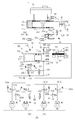
도 1은 본 발명의 실시예에 따른 전자식 브레이크 시스템의 비 제동시의 상태를 나타내는 유압회로도이다.
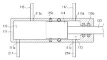
도 2는 본 발명의 실시예에 따른 액압 제공유닛을 나타내는 확대도이다.
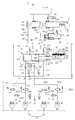
도 3은 유압피스톤이 전진하면서 저압 모드에서 제동 압력을 제공하는 상황을 나타내는 유압회로도이다.
도 4는 유압피스톤이 전진하면서 고압 모드에서 제동 압력을 제공하는 상황을 나타내는 유압회로도이다.
도 5는 유압피스톤이 후진하면서 제동 압력을 제공하는 상황을 나타내는 유압회로도이다.
도 6은 유압피스톤이 후진하면서 고압 모드에서 제동 압력을 해제하는 상황을 나타내는 유압회로도이다.
도 7은 유압피스톤이 후진하면서 저압 모드에서 제동 압력을 해제하는 상황을 나타내는 유압회로도이다.
도 8은 유압피스톤이 전진하면서 제동 압력을 해제하는 상황을 나타내는 유압회로도이다.
도 9와 도 10은 본 발명의 실시예에 따른 전자식 브레이크 시스템이 ABS 작동되는 상태를 나타내는 것으로, 도 9는 유압피스톤이 전진하면서 선별적으로 제동하는 상황을, 도 10은 유압피스톤이 후진하면서 선별적으로 제동하는 상황을 나타내는 유압회로도이다.
도 11은 본 발명의 실시예에 따른 전자식 브레이크 시스템이 비 정상적으로 작동하는 상태를 나타내는 유압회로도이다.
도 12는 본 발명의 실시예에 따른 전자식 브레이크 시스템이 덤프모드로 작동되는 상태를 나타내는 유압회로도이다.
도 13은 본 발명의 실시예에 따른 전자식 브레이크 시스템이 밸런스 모드로 작동되는 상태를 나타내는 유압회로도이다.
도 14는 본 발명의 실시예에 따른 전자식 브레이크 시스템이 검사 모드로 작동되는 상태를 나타내는 유압회로도이다.BRIEF DESCRIPTION OF THE DRAWINGS FIG. 1 is a hydraulic circuit diagram showing a non-synchronized state of an electronic brake system according to an embodiment of the present invention; FIG.
2 is an enlarged view showing a hydraulic pressure providing unit according to an embodiment of the present invention.
3 is a hydraulic circuit diagram showing a situation in which the hydraulic piston advances and provides a braking pressure in the low pressure mode.
4 is a hydraulic circuit diagram showing a situation in which the hydraulic piston advances and provides a braking pressure in a high pressure mode.
5 is a hydraulic circuit diagram showing a situation in which the hydraulic piston provides a braking pressure while reversing.
6 is a hydraulic circuit diagram showing a situation in which the hydraulic pressure piston is released and the braking pressure is released in the high pressure mode.
7 is a hydraulic circuit diagram showing a situation in which the hydraulic pressure piston is released and the braking pressure is released in the low pressure mode.
8 is a hydraulic circuit diagram showing a situation in which the hydraulic pressure piston is advanced and the braking pressure is released.
9 and 10 show a state in which the ABS is actuated by the electromagnetic brake system according to the embodiment of the present invention. Fig. 9 shows a situation in which the hydraulic piston is selectively braked while advancing, Fig. 10 shows a state in which the hydraulic piston is retracted It is a hydraulic circuit diagram showing a situation where the engine is braked.
11 is a hydraulic circuit diagram showing a state in which the electromagnetic brake system according to the embodiment of the present invention operates abnormally.
12 is a hydraulic circuit diagram showing a state in which the electronic brake system according to the embodiment of the present invention is operated in the dump mode.
13 is a hydraulic circuit diagram showing a state in which the electromagnetic brake system according to the embodiment of the present invention is operated in a balanced mode.
14 is a hydraulic circuit diagram showing a state in which the electronic brake system according to the embodiment of the present invention is operated in the inspection mode.
이하에서는 본 발명의 실시 예를 첨부 도면을 참조하여 상세히 설명한다. 이하의 실시 예는 본 발명이 속하는 기술분야에서 통상의 지식을 가진 자에게 본 발명의 사상을 충분히 전달하기 위해 제시하는 것이다. 본 발명은 여기서 제시한 실시 예만으로 한정되지 않고 다른 형태로 구체화될 수도 있다. 도면은 본 발명을 명확히 하기 위해 설명과 관계 없는 부분의 도시를 생략하고, 이해를 돕기 위해 구성요소의 크기를 다소 과장하여 표현할 수 있다.Hereinafter, embodiments of the present invention will be described in detail with reference to the accompanying drawings. The following embodiments are provided to fully convey the spirit of the present invention to a person having ordinary skill in the art to which the present invention belongs. The present invention is not limited to the embodiments shown herein but may be embodied in other forms. For the sake of clarity, the drawings are not drawn to scale, and the size of the elements may be slightly exaggerated to facilitate understanding.
도 1은 본 발명의 실시예에 따른 전자식 브레이크 시스템(1)의 비 제동시의 상태를 나타내는 유압회로도이다.Fig. 1 is a hydraulic circuit diagram showing the non-synchronized state of the
도 1을 참조하면, 전자식 브레이크 시스템(1)은 통상적으로, 액압을 발생시키는 마스터 실린더(20)와, 마스터 실린더(20)의 상부에 결합되어 오일을 저장하는 리저버(30)와, 브레이크 페달(10)의 답력에 따라 마스터 실린더(20)를 가압하는 인풋로드(12)와, 액압이 전달되어 각 차륜(RR, RL, FR, FL)의 제동을 수행하는 휠 실린더(40)와, 브레이크 페달(10)의 변위를 감지하는 페달 변위센서(11) 및 브레이크 페달(10)의 답력에 따른 반력을 제공하는 시뮬레이션 장치(50)를 구비한다.1, the
마스터 실린더(20)는 적어도 하나의 챔버를 구비하도록 구성되어 액압을 발생시킬 수 있다. 일 예로, 마스터 실린더(20)는 두 개의 챔버를 구비하도록 구성되고, 각각의 챔버에는 제1 피스톤(21a)과 제2 피스톤(22a)이 마련되며, 제1 피스톤(21a)은 인풋로드(12)와 연결될 수 있다. 그리고 마스터 실린더(20)는 두 개의 챔버로부터 각각 액압이 배출되는 제1 및 제2 유압포트(24a, 24b)를 형성할 수 있다.The
한편, 마스터 실린더(20)는 두 개의 챔버를 가짐으로써 고장시 안전을 확보할 수 있다. 예컨대, 두 개의 챔버 중 하나의 챔버는 차량의 우측 전륜(FR)과 좌측 후륜(RL)에 연결되고, 다른 하나의 챔버는 좌측 전륜(FL)과 우측 후륜(RR)에 연결될 수 있다. 이와 같이, 두 개의 챔버를 독립적으로 구성함으로써 한 쪽 챔버가 고장나는 경우에도 차량의 제동이 가능하도록 할 수 있다.On the other hand, the
또는 도면에 도시된 것과 달리 두 개의 챔버 중 하나의 챔버를 두 개의 전륜(FR, FL)에, 그리고 다른 하나의 챔버를 두 개의 후륜(RR, RL)에 연결할 수도 있다. 그 밖에도 두 개의 챔버 중 하나의 챔버를 좌측 전륜(FL)과 좌측 후륜(RL)에, 그리도 갇른 하나의 챔버를 우측 후륜(RR)과 우측 전륜(FR)에 연결할 수도 있다. 즉, 마스터 실린더(20)의 챔버에 연결되는 휠의 위치는 다양하게 구성될 수 있다.Or one of the two chambers may be connected to the two front wheels FR and FL, and the other chamber may be connected to the two rear wheels RR and RL, as shown in the figure. In addition, one of the two chambers may be connected to the left front wheel FL and the left rear wheel RL, and one chamber may be connected to the right rear wheel RR and the right front wheel FR. That is, the positions of the wheels connected to the chambers of the
또한, 마스터 실린더(20)의 제1 피스톤(21a)과 제2 피스톤(22a) 사이에는 제1 스프링(21b)이 마련되고, 제2 피스톤(22a)과 마스터 실린더(20)의 끝단 사이에는 제2 스프링(22b)이 마련될 수 있다.A
제1 스프링(21b)과 제2 스프링(22b)은 두 챔버에 각각 마련되고, 브레이크 페달(10)의 변위가 달라짐에 따라 제1 피스톤(21a)과 제2 피스톤(22a)이 압축되면서 제1 스프링(21b)과 제2 스프링(22b)에 탄성력이 저장된다. 그리고 제1 피스톤(21a)을 미는 힘이 탄성력 보다 작아지면 제1 스프링(21b)과 제2 스프링(22b)이 저장된 탄성력을 이용하여 제1 및 제2 피스톤(21a, 22a)을 밀어서 원상복귀 시킬 수 있다.The
한편, 마스터 실린더(20)의 제1 피스톤(21a)을 가압하는 인풋로드(12)는 제1 피스톤(21a)과 밀착되게 접촉될 수 있다. 즉, 마스터 실린더(20)와 인풋로드(12) 사이의 갭(gap)이 존재하지 않을 수 있다. 따라서 브레이크 페달(10)을 밞으면 페달 무효 스트로크 구간 없이 직접적으로 마스터 실린더(20)를 가압할 수 있다.On the other hand, the
시뮬레이션 장치(50)는 후술할 제1 백업유로(251)와 연결되어 브레이크 페달(10)의 답력에 따른 반력을 제공할 수 있다. 운전자가 제공하는 답력을 보상하는 만큼 반력이 제공됨으로써 운전자는 의도하는 대로 세밀하게 제동력을 조절할 수 있게 된다.The
도 1을 참고하면, 시뮬레이션 장치(50)는 마스터 실린더(20)의 제1 유압포트(24a)에서 유출되는 오일을 저장할 수 있도록 마련된 시뮬레이션 챔버(51)와 시뮬레이션 챔버(51) 내에 마련된 반력 피스톤(52)과 이를 탄성 지지하는 반력 스프링(53)을 구비하는 페달 시뮬레이터 및 시뮬레이션 챔버(51)의 후단부에 연결된 시뮬레이터 밸브(54)를 포함한다.1, the
반력 피스톤(52)과 반력 스프링(53)은 시뮬레이션 챔버(51)로 유입되는 오일에 의해 시뮬레이션 챔버(51) 내에서 일정 범위의 변위를 갖도록 설치된다.The
한편, 도면에 도시된 반력 스프링(53)은 반력 피스톤(52)에 탄성력을 제공할 수 있는 하나의 실시예에 불과한 것으로, 형상 변형에 의해 탄성력을 저장할 수 있는 다양한 실시예들을 포함할 수 있다. 일 예로, 고무 등의 재질로 마련되거나, 코일 또는 판 형상을 구비함으로써 탄성력을 저장할 수 있는 다양한 부재를 포함한다.On the other hand, the reaction force spring 53 shown in the drawings is only one embodiment capable of providing an elastic force to the
시뮬레이터 밸브(54)는 시뮬레이션 챔버(51)의 후단과 리저버(30)를 연결하는 유로에 마련될 수 있다. 시뮬레이션 챔버(51)의 전단은 마스터 실린더(20)와 연결되고, 시뮬레이션 챔버(51)의 후단은 시뮬레이터 밸브(54)를 통해 리저버(30)와 연결될 수 있다. 따라서 반력 피스톤(52)이 복귀하는 경우에도 시뮬레이터 밸브(54)를 통해 리저버(30)의 오일이 유입됨으로써 시뮬레이션 챔버(51)의 내부 전체가 오일로 채워질 수 있다.The
한편, 도면에는 여러 개의 리저버(30)가 도시되어 있고 각각의 리저버(30)는 동일한 도면 부호를 사용하고 있다. 다만, 이들 리저버는 동일 부품으로 마련되거나 서로 다른 부품으로 마련될 수 있다. 일 예로, 시뮬레이션 장치(50)와 연결되는 리저버(30)는 마스터 실린더(20)와 연결되는 리저버(30)와 동일하거나, 마스터 실린더(20)와 연결되는 리저버(30)와 별도로 오일을 저장할 수 있는 저장소일 수 있다.In the meantime,
한편, 시뮬레이터 밸브(54)는 평소 닫힌 상태를 유지하는 평상시 폐쇄형 솔레노이드 밸브로 구성될 수 있다. 시뮬레이터 밸브(54)는 운전자가 브레이크 페달(10)에 답력을 가하는 경우 개방되어 시뮬레이션 챔버(51) 내의 오일을 리저버(30)로 전달할 수 있다.On the other hand, the
또한, 페달 시뮬레이터와 리저버(30) 사이에는 시뮬레이터 밸브(54)와 병렬 연결되도록 시뮬레이터 체크밸브(55)가 설치될 수 있다. 시뮬레이터 체크밸브(55)는 리저버(30)의 오일이 시뮬레이션 챔버(51)로 흐르는 것을 허용하되, 시뮬레이션 챔버(51)의 오일이 체크밸브(55)가 설치되는 유로를 통해 리저버(30)로 흐르는 것을 차단할 수 있다. 브레이크 페달(10)의 답력 해제시 시뮬레이터 체크밸브(55)를 통해 오일이 시뮬레이션 챔버(51) 내로 공급될 수 있기 때문에 페달 시뮬레이터 압력의 빠른 리턴이 보장될 수 있다.Further, a
페달 시뮬레이션 장치(50)의 동작 모습에 대하여 설명하면, 운전자가 브레이크 페달(10)에 답력을 제공 시 페달 시뮬레이터의 반력 피스톤(52)이 반력 스프링(53)을 압축하면서 밀어내는 시뮬레이션 챔버(51) 내의 오일은 시뮬레이터 밸브(54)를 통해 리저버(30)로 전달되고, 이 과정에서 운전자는 페달감을 제공받게 된다. 그리고 운전자가 브레이크 페달(10)에 답력을 해제시 반력 스프링(53)이 반력 피스톤(52)을 밀어내면서 반력 피스톤(52)이 원래의 상태로 복귀하고, 리저버(30)의 오일이 시뮬레이터 밸브(54)가 설치되는 유로와 체크밸브(55)가 설치되는 유로를 통해 시뮬레이션 챔버(51) 내에 유입되면서 시뮬레이션 챔버(51) 내부에 오일이 가득 찰 수 있다.The simulating chamber 51 which pushes the reaction force spring 53 while compressing the
이와 같이, 시뮬레이션 챔버(51) 내부는 항상 오일이 채워진 상태이기 때문에 시뮬레이션 장치(50)의 작동 시 반력 피스톤(52)의 마찰이 최소화되어 시뮬레이션 장치(50)의 내구성이 향상됨은 물론, 외부로부터 이물질의 유입이 차단될 수 있다.Since the inside of the simulation chamber 51 is filled with oil at all times, friction of the
본 발명의 실시예에 따른 전자식 브레이크 시스템(1)은 브레이크 페달(10)의 변위를 감지하는 페달 변위센서(11)로부터 운전자의 제동의지를 전기적 신호로 전달받아 기계적으로 작동하는 액압 공급장치(100)와, 각각 두 개의 차륜(RR, RL, FR, FL)에 마련되는 휠 실린더(40)로 전달되는 액압의 흐름을 제어하는 제1 및 제2 유압서킷(201, 202)으로 구성된 유압 제어유닛(200)과, 상기 제1 유압포트(24a)와 제1 유압서킷(201)을 연결하는 제1 백업유로(251)에 마련되어 액압의 흐름을 제어하는 제1 컷밸브(261)와, 제2 유압포트(24b)와 제2 유압서킷(202)을 연결하는 제2 백업유로(252)에 마련되어 액압의 흐름을 제어하는 제2 컷밸브(262)와, 액압 정보와 페달 변위 정보를 기반으로 액압 공급장치(100)와 밸브들(54, 60, 221a, 221b, 221c, 221d, 222a, 222b, 222c, 222d, 233, 235, 236, 243)을 제어하는 전자제어유닛(ECU, 미도시)을 포함할 수 있다.An
액압 공급장치(100)는 휠 실린더(40)로 전달되는 오일 압력을 제공하는 액압 제공유닛(110)과, 페달 변위센서(11)의 전기적 신호에 의해 회전력을 발생시키는 모터(120)와, 모터(120)의 회전운동을 직선운동으로 변환하여 액압 제공유닛(110)에 전달하는 동력변환부(130)를 포함할 수 있다. 또는 액압 제공유닛(110)은 모터(120)에서 공급되는 구동력이 아니라 고압 어큐뮬레이터에서 제공되는 압력에 의해 동작할 수도 있다.The hydraulic
다음으로 도 2를 참고하여 본 발명의 실시예에 따른 액압 제공유닛(110)에 대하여 설명하기로 한다. 도 2는 본 발명의 실시예에 따른 액압 제공유닛(110)을 나타내는 확대도이다.Next, the hydraulic
액압 제공유닛(110)은 오일을 공급받아 저장되는 압력챔버가 형성되는 실린더블록(111)과, 실린더블록(111) 내에 수용되는 유압피스톤(114)과, 유압피스톤(114)과 실린더블록(111) 사이에 마련되어 압력챔버를 밀봉하는 실링부재(115: 115a, 115b)와, 유압피스톤(114)의 후단에 연결되어 동력변환부(130)에서 출력되는 동력을 유압피스톤(114)으로 전달하는 구동축(133)을 포함한다.The hydraulic
압력챔버는 유압피스톤(114)의 전방(전진 방향, 도면의 좌측 방향)에 위치하는 제1 압력챔버(112)와, 유압피스톤(114)의 후방(후진 방향, 도면의 우측 방향)에 위치하는 제2 압력챔버(113)를 포함할 수 있다. 즉, 제1 압력챔버(112)는 실린더블록(111)과 유압피스톤(114)의 전단에 의해 구획되며, 유압피스톤(114)의 이동에 따라 체적이 달라지도록 마련되고, 제2 압력챔버(113)는 실린더블록(111)과 유압피스톤(114)의 후단에 의해 구획되며, 유압피스톤(114)의 이동에 따라 체적이 달라지도록 마련된다.The pressure chamber includes a
제1 압력챔버(112)는 실린더블록(111)의 후방 측에 형성되는 제1 연통홀(111a)을 통해 제1 유압유로(211)에 연결되고, 실린더블록(111)의 전방 측에 형성되는 제2 연통홀(111b)을 통해 제4 유압유로(214)에 연결된다. 제1 유압유로(211)는 제1 압력탬버(112)와 제1 및 제2 유압서킷(201, 202)을 연결한다. 그리고 제1 유압유로(211)는 제1 유압서킷(201)과 연통되는 제2 유압유로(212)와 제2 유압서킷(202)과 연통되는 제3 유압유로(212)로 분기된다. 제4 유압유로(214)는 제2 압력챔버(113)과 제1 및 제2 유압서킷(201, 202)을 연결한다. 그리고 제4 유압유로(214)는 제1 유압서킷(201)과 연통되는 제5 유압유로(215)와 제2 유압서킷(202)과 연통되는 제6 유압유로(216)로 분기된다.The
실링부재(115)는 유압피스톤(114)과 실린더블록(111) 사이에 마련되어 제1 압력챔버(112)와 제2 압력챔버(113) 사이를 밀봉하는 피스톤 실링부재(115a)와 구동축(133)과 실린더블록(111) 사이에 마련되어 제2 압력챔버(113)와 실린더블록(111)의 개구를 밀봉하는 구동축 실링부재(115b)를 포함한다. 즉, 유압피스톤(114)의 전진 또는 후진에 의해 발생하는 제1 압력챔버(112)의 액압 또는 부압은 피스톤 실링부재(115a)에 의해 차단되어 제2 압력챔버(113)에 누설되지 않고 제1 및 제4 유압유로(211, 214)에 전달될 수 있다. 그리고 유압피스톤(114)의 전진 또는 후진에 의해 발생하는 제2 압력챔버(113)의 액압 또는 부압은 구동축 실링부재(115b)에 의해 차단되어 실린더블록(111)에 누설되지 않을 수 있다.The sealing
제1 및 제2 압력챔버(112, 113)는 각각 덤프유로(116, 117)에 의해 리저버(30)와 연결되고, 리저버(30)로부터 오일을 공급받아 저장하거나 제1 또는 제2 압력챔버(112, 113)의 오일을 리저버(30)로 전달할 수 있다. 일 예로, 덤프유로(116, 117)는 제1 압력챔버(112)로부터 분기되어 리저버(30)와 연결되는 제1 덤프유로(116)과, 제2 압력챔버(113)로부터 분기되어 리저버(30)와 연결되는 제2 덤프유로(117)를 포함할 수 있다.The first and
또한, 제1 압력챔버(112)는 전방 측에 형성되는 제5 연통홀(111f)를 통해 제1 덤프유로(116)와 연결되고, 제2 압력챔버(113)는 후방 측에 형성되는 제6 연통홀(111e)을 통해 제2 덤프유로(117)와 연결될 수 있다.The
그리고 제1 압력챔버(112)의 전방에는 제1 유압유로(211)와 연통되는 제1 연통홀(111a)이 형성되고, 제1 압력챔버(112)의 후방에는 제4 유압유로(214)와 연통되는 제2 연통홀(111b)이 형성될 수 있다. 그리고 제1 압력챔버(112)에는 제1 덤프유로(116)와 연통되는 제3 연통홀(111c)이 더 형성될 수 있다.A
또한, 제2 압력챔버(113)에는 제3 유압유로(213)와 연통되는 제3 연통홀(111c)과, 제2 덤프유로(117)와 연통되는 제4 연통홀(111d)이 형성될 수 있다.A
다시 도 1을 참고하여, 제1 압력챔버(112)와 제2 압력챔버(113)에 연결되는 유로들(211, 212, 213, 214, 215, 216, 217)과 밸드들(231, 232, 233, 234, 235, 236, 241, 242, 243)에 대하여 설명하기로 한다.Referring again to FIG. 1, flow
제2 유압유로(212)는 제1 유압서킷(201)과 연통되고, 제3 유압유로(213)는 제2 유압서킷(202)과 연통될 수 있다. 따라서, 유압피스톤(114)의 전진에 의해 제1 유압서킷(201)과 제2 유압서킷(202)으로 액압이 전달될 수 있다.The second
또한, 본 발명의 실시예에 따른 전자식 브레이크 시스템(1)은 제2 및 제3 유압유로(212, 213)에 각각 마련되어 오일의 흐름을 제어하는 제1 제어밸브(231)와 제2 제어밸브(232)를 포함할 수 있다.The
그리고 제1 및 제2 제어밸브(231, 232)는 제1 압력챔버(112)에서 제1 또는 제2 유압서킷(201, 202)으로 향하는 방향의 오일 흐름만을 허용하고, 반대 방향으로의 오일 흐름은 차단하는 체크밸브로 마련될 수 있다. 즉, 제1 또는 제2 제어밸브(231, 232)는 제1 압력챔버(112)의 액압이 제1 또는 제2 유압서킷(201, 202)으로 전달되는 것을 허용하면서도, 제1 또는 제2 유압서킷(201, 202)의 액압이 제2 또는 제3 유압유로(212, 213)를 통해 제1 압력챔버(112)로 누설되는 것은 방지할 수 있다.The first and
한편, 제4 유압유로(213)는 도중에 제5 유압유로(215)와 제6 유압유로(216)로 분기되어 제1 유압서킷(201)과 제2 유압서킷(202)에 모두 연통될 수 있다. 일 예로, 제4 유압유로(214)에서 분기되는 제5 유압유로(215)는 제1 유압서킷(201)과 연통되고, 제4 유압유로(214)에서 분기되는 제6 유압유로(216)는 제2 유압서킷(202)과 연통될 수 있다. 따라서, 유압피스톤(114)의 후진에 의해 제1 유압서킷(201)과 제2 유압서킷(202) 모두에 액압이 전달될 수 있다.On the other hand, the fourth
또한, 본 발명의 실시예에 따른 전자식 브레이크 시스템(1)은 제5 유압유로(215)에 마련되어 오일의 흐름을 제어하는 제3 제어밸브(233)와 제6 유압유로(216)에 마련되어 오일의 흐름을 제어하는 제4 제어밸브(234)를 포함할 수 있다.The
제3 제어밸브(233)는 제2 압력챔버(113)와 제1 유압서킷(201) 사이의 오일 흐름을 제어하는 양방향 제어밸브로 마련될 수 있다. 그리고 제3 제어밸브(233)는 평상시 닫혀있다가 전자제어유닛으로부터 개방신호를 받으면 밸브가 열리도록 작동하는 노말 클로즈 타입(Normal Cloesd type)의 솔레노이드 밸브로 마련될 수 있다.The
그리고 제4 제어밸브(234)는 제2 압력챔버(113)에서 제2 유압서킷(202)으로 향하는 방향의 오일 흐름만을 허용하고, 반대 방향으로의 오일 흐름은 차단하는 체크밸브로 마련될 수 있다. 즉, 제4 제어밸브(234)는 제2 유압서킷(202)의 액압이 제6 유압유로(216)와 제4 유압유로(214)를 통해 제2 압력챔버(113)로 누설되는 것은 방지할 수 있다.And the
또한, 본 발명의 실시예에 따른 전자식 브레이크 시스템(1)은 제2 유압유로(212)와 제3 유압유로(213)를 연결하는 제7 유압유로(217)에 마련되어 오일의 흐름을 제어하는 제5 제어밸브(235)와, 제2 유압유로(212)와 제7 유압유로(217)를 연결하는 제8 유압유로(218)에 마련되어 오일의 흐름을 제어하는 제6 제어밸브(236)를 포함할 수 있다. 그리고 제5 제어밸브(235)와 제6 제어밸브(236)는 평상시 닫혀있다가 전자제어유닛으로부터 개방신호를 받으면 밸브가 열리도록 작동하는 노말 클로즈 타입(Normal Cloesd type)의 솔레노이드 밸브로 마련될 수 있다.The
제5 제어밸브(235)와 제6 제어밸브(236)는 제1 제어밸브(231) 또는 제2 제어밸브(232)에 이상이 발생하였을 때, 개방되도록 작동하여 제1 압력챔버(112)의 액압이 제1 유압서킷(201)과 제2 유압서킷(202)에 모두 전달될 수 있도록 할 수 있다.The
그리고 제5 제어밸브(235)와 제6 제어밸브(236)는 휠 실린더(40)의 액압을 빼내어 제1 압력챔버(112)로 보내는 때에 개방되도록 작동할 수 있다. 제2 유압유로(212)와 제3 유압유로(213)에 마련되는 제1 제어밸브(231)와 제2 제어밸브(232)가 일 방향 오일 흐름만을 허용하는 체크밸브로 마련되기 때문이다.And the
또한, 본 발명의 실시예에 따른 전자식 브레이크 시스템(1)은 제1 및 제2 덤프유로(116, 117)에 각각 마련되어 오일의 흐름을 제어하는 제1 덤프밸브(241)와 제2 덤프밸브(242)를 더 포함할 수 있다. 덤프밸브(241, 242)는 리저버(30)에서 제1 또는 제2 압력챔버(112, 113)로의 방향만을 개방하고, 반대 방향은 폐쇄하는 체크밸브일 수 있다. 즉, 제1 덤프밸브(241)은 리저버(30)에서 제1 압력챔버(112)로 오일이 흐를 수 있도록 허용하되, 제1 압력챔버(112)에서 리저버(30)로 오일이 흐르는 것은 차단하는 체크밸브일 수 있고, 제2 덤프밸브(242)은 리저버(30)에서 제2 압력챔버(113)로 오일이 흐를 수 있도록 허용하되, 제2 압력챔버(113)에서 리저버(30)로 오일이 흐르는 것은 차단하는 체크밸브일 수 있다.The
또한, 제2 덤프유로(117)는 바이패스 유로를 포함할 수 있고, 바이패스 유로에는 제2 압력챔버(113)와 리저버(30) 사이의 오일 흐름을 제어하는 제3 덤프밸브(243)가 설치될 수 있다.The
제3 덤프밸브(243)는 양방향 흐름을 제어할 수 있는 솔레노이드 밸브로 마련될 수 있고, 정상상태에서는 개방되어 있다가 전자제어유닛에서 폐쇄신호를 받으면 밸브가 닫히도록 작동하는 노말 오픈 타입(Normal Open type)의 솔레노이드 밸브로 마련될 수 있다.The
본 발명의 실시예에 따른 전자식 브레이크 시스템(1)의 액압 제공유닛(110)은 복동식으로 동작할 수 있다. 즉, 유압피스톤(114)이 전진하면서 제1 압력챔버(112)에 발생되는 액압은 제1 유압유로(211)와 제2 유압유로(212)를 통해 제1 유압서킷(201)에 전달되어 우측 전륜(FR)과 좌측 후륜(LR)에 설치되는 휠 실린더(40)를 작용시킬 수 있고, 제1 유압유로(211)와 제3 유압유로(213)를 통해 제2 유압서킷(202)에 전달되어 우측 후륜(RR)과 좌측 전륜(FL)에 설치되는 휠 실린더(40)를 작용시킬 수 있다.The hydraulic
마찬가지로, 유압피스톤(114)이 후진하면서 제2 압력챔버(113)에 발생되는 액압은 제4 유압유로(214)와 제5 유압유로(215)를 통해 제1 유압서킷(201)에 전달되어 우측 전륜(FR)과 좌측 후륜(LR)에 설치되는 휠 실린더(40)를 작용시킬 수 있고, 제4 유압유로(214)와 제6 유압유로(216)를 통해 제2 유압서킷(202)에 전달되어 우측 후륜(RR)과 좌측 전륜(FL)에 설치되는 휠 실린더(40)를 작용시킬 수 있다.Similarly, the hydraulic pressure generated in the
또한, 유압피스톤(114)이 후진하면서 제1 압력챔버(112)에 발생되는 부압은 우측 전륜(FR)과 좌측 후륜(LR)에 설치되는 휠 실린더(40)의 오일을 흡입하여 제1 유압서킷(201), 제2 유압유로(212), 및 제1 유압유로(211)를 통해 제1 압력챔버(112)로 전달시킬 수 있고, 우측 후륜(RR)과 좌측 전륜(FL)에 설치되는 휠 실린더(40)의 오일을 흡입하여 제2 유압서킷(202), 제3 유압유로(213), 및 제1 유압유로(211)를 통해 제1 압력챔버(112)로 전달시킬 수 있다.The negative pressure generated in the
다음으로 액압 공급장치(100)의 모터(120)와 동력변환부(130)에 대하여 설명하기로 한다.Next, the
모터(120)는 전자제어유닛(ECU, 미도시)으로부터 출력된 신호에 의해 회전력을 발생시키는 장치로서, 정방향 또는 역방향으로 회전력을 발생시킬 수 있다. 모터(120)의 회전 각속도와 회전각은 정밀하게 제어될 수 있다. 이러한 모터(120)는 이미 널리 알려진 공지의 기술이므로 상세한 설명은 생략하기로 한다.The
한편, 전자제어유닛은 모터(120)를 포함하여 후술할 본 발명의 전자식 브레이크 시스템(1)에 구비된 밸브들(54, 60, 221a, 221b, 221c, 221d, 222a, 222b, 222c, 222d, 233, 235, 236, 243)을 제어한다. 브레이크 페달(10)의 변위에 따라 복수의 밸브들이 제어되는 동작에 대해서는 후술하기로 한다.On the other hand, the electronic control unit includes valves (54, 60, 221a, 221b, 221c, 221d, 222a, 222b, 222c, 222d, 233, 235, 236, and 243. The operation in which a plurality of valves are controlled according to the displacement of the
모터(120)의 구동력은 동력변환부(130)를 통해 유압피스톤(114)의 변위를 발생시키고, 압력챔버 내에서 유압피스톤(114)이 슬라이딩 이동하면서 발생하는 액압은 제1 및 제2 유압유로(211, 212)를 통해 각 차륜(RR, RL, FR, FL)에 설치된 휠 실린더(40)로 전달된다.The driving force of the
동력변환부(130)는 회전력을 직선운동으로 변환하는 장치로서, 일 예로 웜샤프트(131)와 웜휠(132)과 구동축(133)으로 구성될 수 있다.The
웜샤프트(131)는 모터(120)의 회전축과 일체로 형성될 수 있고, 외주면에 웜이 형성되어 웜휠(132)과 맞물리도록 결합하여 웜휠(132)을 회전시킨다. 웜휠(132)은 구동축(133)과 맞물리도록 연결되어 구동축(133)을 직선 이동시키고, 구동축(133)은 유압피스톤(114)과 연결되어 유압피스톤(114)을 실린더블록(111) 내에서 슬라이딩 이동시킨다.The
이상의 동작들을 다시 설명하면, 브레이크 페달(10)에 변위가 발생하면서 페달 변위센서(11)에 의해 감지된 신호는 전자제어유닛(ECU, 미도시)에 전달되고, 전자제어유닛은 모터(120)를 일 방향으로 구동시켜 웜샤프트(131)를 일 방향으로 회전시킨다. 웜샤프트(131)의 회전력은 웜휠(132)을 거쳐 구동축(133)에 전달되고, 구동축(133)과 연결된 유압피스톤(114)이 전진 이동하면서 제1 압력챔버(112)에 액압을 발생시킨다.A signal sensed by the
반대로, 브레이크 페달(10)에 답력이 제거되면 전자제어유닛은 모터(120)를 반대 방향으로 구동시켜 웜샤프트(131)가 반대 방향으로 회전한다. 따라서 웜휠(132) 역시 반대로 회전하고 구동축(133)과 연결된 유압피스톤(114)이 복귀하면서(후진 이동하면서) 제1 압력챔버(112)에 부압을 발생시킨다.On the other hand, when the
한편, 액압과 부압의 발생은 위와 반대 방향으로도 가능하다. 즉, 브레이크 페달(10)에 변위가 발생하면서 페달 변위센서(11)에 의해 감지된 신호는 전자제어유닛(ECU, 미도시)에 전달되고, 전자제어유닛은 모터(120)를 반대 방향으로 구동시켜 웜샤프트(131)를 반대 방향으로 회전시킨다. 웜샤프트(131)의 회전력은 웜휠(132)을 거쳐 구동축(133)에 전달되고, 구동축(133)과 연결된 유압피스톤(114)이 후진 이동하면서 제2 압력챔버(113)에 액압을 발생시킨다.On the other hand, the hydraulic pressure and the negative pressure can be generated in the opposite direction. That is, when a displacement occurs in the
반대로, 브레이크 페달(10)에 답력이 제거되면 전자제어유닛은 모터(120)를 일 방향으로 구동시켜 웜샤프트(131)가 일 방향으로 회전한다. 따라서 웜휠(132) 역시 반대로 회전하고 구동축(133)과 연결된 유압피스톤(114)이 복귀하면서(전진 이동하면서) 제2 압력챔버(113)에 부압을 발생시킨다.On the other hand, when the pressing force is removed from the
이처럼 액압 공급장치(100)는 모터(120)로부터 발생된 회전력의 회전방향에 따라 액압을 휠 실린더(40)로 전달하거나 액압을 흡입하여 리저버(30)로 전달하는 역할을 수행하게 된다.The hydraulic
한편, 모터(120)가 일 방향으로 회전하는 경우 제1 압력챔버(112)에 액압이 발생하거나 제2 압력챔버(113)에 부압이 발생할 수 있는데, 액압을 이용하여 제동할 것인지, 아니면 부압을 이용하여 제동을 해제할 것인지는 밸브들(54, 60, 221a, 221b, 221c, 221d, 222a, 222b, 222c, 222d, 233, 235, 236, 243)을 제어함으로써 결정될 수 있다. 이에 대하여는 뒤에서 상세히 설명하기로 한다.On the other hand, when the
도면에 도시되지는 않았지만 동력변환부(130)는 볼스크류 너트 조립체로 구성될 수도 있다. 예컨대, 모터(120)의 회전축과 일체로 형성되거나 모터(120)의 회전축과 같이 회전하도록 연결되는 스크류와, 회전이 제한된 상태로 스크류와 나사결합되어 스크류의 회전에 따라 직선운동하는 볼너트로 구성될 수 있다. 유압피스톤(114)은 동력변환부(130)의 볼너트와 연결되어 볼너트의 직선운동에 의해 압력챔버를 가압한다. 이와 같은 볼스크류 너트 조립체의 구조는 회전운동을 직선운동으로 변환시키는 장치로서 이미 널리 알려진 공지의 기술이므로 상세한 설명은 생략하기로 한다.Although not shown in the drawing, the
그리고 본 발명의 실시예에 따른 동력변환부(130)는 상기 볼스크류 너트 조립체의 구조 이외에 회전운동을 직선운동으로 변환시킬 수 있다면 어떠한 구조를 갖더라도 채용 가능한 것으로 이해되어야 한다.It should be understood that the
또한, 본 발명의 실시예에 따른 전자식 브레이크 시스템(1)은 비 정상적으로 작동하는 때에 마스터 실린더(20)로부터 토출된 오일을 직접 휠 실린더(40)로 공급할 수 있는 제1 및 제2 백업유로(251, 252)를 더 포함할 수 있다.The
제1 백업유로(251)에는 오일의 흐름을 제어하는 제1 컷밸브(261)가 마련되고, 제2 백업유로(252)에는 오일의 흐름을 제어하는 제2 컷밸브(262)가 마련될 수 있다. 또한, 제1 백업유로(251)는 제1 유압포트(24a)와 제1 유압서킷(201)을 연결하고, 제2 백업유로(252)는 제2 유압포트(24b)와 제2 유압서킷(202)을 연결할 수 있다.A
그리고 제1 및 제2 컷밸브(261, 262)는 정상상태에서는 개방되어 있다가 전자제어유닛에서 폐쇄신호를 받으면 밸브가 닫히도록 작동하는 노말 오픈 타입(Normal Open type)의 솔레노이드 밸브로 마련될 수 있다.The first and
다음으로, 도 1을 참고하여 본 발명의 실시예에 따른 유압 제어유닛(200)에 대하여 설명하기로 한다.Next, the
유압 제어유닛(200)은 액압을 공급받아 각각 두 개의 차륜을 제어하는 제1 유압서킷(201)과, 제2 유압서킷(202)으로 이루어질 수 있다. 일 예로, 제1 유압서킷(201)은 우측 전륜(FR)과 좌측 후륜(RL)을 제어하고, 제2 유압서킷(202)은 좌측 전륜(FL)과 우측 후륜(RR)을 제어할 수 있다. 그리고 각각의 차륜(FR, FL, RR, RL)에는 휠 실린더(40)가 설치되어 액압을 공급받아 제동이 이루어진다.The
제1 유압서킷(201)은 제1 유압유로(211) 및 제2 유압유로(212)와 연결되어 액압 공급장치(100)로부터 액압을 제공받고, 제2 유압유로(212)는 우측 전륜(FR)과 좌측 후륜(RL)으로 연결되는 두 유로로 분기된다. 마찬가지로, 제2 유압서킷(202)은 제1 유압유로(211) 및 제3 유압유로(213)와 연결되어 액압 공급장치(100)로부터 액압을 제공받고, 제3 유압유로(213)는 좌측 전륜(FL)과 우측 후륜(RR)으로 연결되는 두 유로로 분기된다.The first
유압서킷(201, 202)은 액압의 흐름을 제어하도록 복수의 인렛밸브(221: 221a, 221b, 221c, 221d)를 구비할 수 있다. 일 예로, 제1 유압서킷(201)에는 제1 유압유로(211)와 연결되어 두 개의 휠 실린더(40)로 전달되는 액압을 각각 제어하는 두 개의 인렛밸브(221a, 221b)가 마련될 수 있다. 또한, 제2 유압서킷(202)에는 제2 유압유로(212)와 연결되어 휠 실린더(40)로 전달되는 액압을 각각 제어하는 두 개의 인렛밸브(221c, 221d)가 마련될 수 있다.The
그리고 인렛밸브(221)는 휠 실린더(40)의 상류측에 배치되며 정상상태에서는 개방되어 있다가 전자제어유닛에서 폐쇄신호를 받으면 밸브가 닫히도록 작동하는 노말 오픈 타입(Normal Open type)의 솔레노이드 밸브로 마련될 수 있다.The inlet valve 221 is disposed on the upstream side of the
또한, 유압서킷(201, 202)은 각각의 인렛밸브(221a, 221b, 221c, 221d)들의 전방과 후방을 연결하는 바이패스 유로에 마련되는 체크밸브(223a, 223b, 223c, 223d)들을 포함할 수 있다. 체크밸브(223a, 223b, 223c, 223d)들은 휠 실린더(40)에서 액압 제공유닛(110) 방향으로의 오일의 흐름만을 허용하고, 액압 제공유닛(110)에서 휠 실린더(40) 방향으로의 오일의 흐름은 제한하도록 마련될 수 있다. 체크밸브(223a, 223b, 223c, 223d)들은 휠 실린더(40)의 제동압을 신속하게 뺄 수 있도록 할 수 있고, 인렛밸브(221a, 221b, 221c, 221d)들이 정상적으로 작동하지 않는 경우에 휠 실린더(40)의 액압이 액압 제공유닛(110)으로 유입되도록 할 수 있다.The
또한, 유압서킷(201, 202)은 제동 해제시 성능향상을 위하여 리저버(30)와 연결되는 복수의 아웃렛밸브(222: 222a, 222b, 222c, 222d)를 더 구비할 수 있다. 아웃렛밸브(222)는 각각 휠 실린더(40)와 연결되어 각 차륜(RR, RL, FR, FL)으로부터 액압이 빠져나가는 것을 제어한다. 즉, 아웃렛밸브(222)는 각 차륜(RR, RL, FR, FL)의 제동압력을 감지하여 감압제동이 필요한 경우 선택적으로 개방되어 압력을 제어할 수 있다.The
그리고 아웃렛밸브(222)는 평상시 닫혀있다가 전자제어유닛으로부터 개방신호를 받으면 밸브가 열리도록 작동하는 노말 클로즈 타입(Normal Cloesd type)의 솔레노이드 밸브로 마련될 수 있다.And the outlet valve 222 may be provided with a solenoid valve of a normal closed type which is normally closed and operates to open the valve when receiving an open signal from the electronic control unit.
또한, 유압 제어유닛(200)은 백업유로(251, 252)와 연결될 수 있다. 일 예로, 제1 유압서킷(201)은 제1 백업유로(251)와 연결되어 마스터 실린더(20)로부터 액압을 제공받고, 제2 유압서킷(202)은 제2 백업유로(252)와 연결되어 마스터 실린더(20)로부터 액압을 제공받을 수 있다.Further, the
이 때, 제1 백업유로(251)는 제1 및 제2 인렛밸브(221a, 221b)의 상류에서 제1 유압서킷(201)에 합류할 수 있다. 마찬가지로, 제2 백업유로(252)는 제3 및 제4 인렛밸브(221c, 221d)의 상류에서 제2 유압서킷(202)에 합류할 수 있다. 따라서, 제1 및 제2 컷밸브(261, 262)를 폐쇄하는 경우 액압 공급장치(100)에서 제공되는 액압을 제1 및 제2 유압서킷(201, 202)을 통해 휠 실린더(40)로 공급할 수 있고, 제1 및 제2 컷밸브(261, 262)를 개방하는 경우 마스터 실린더(20)에서 제공되는 액압을 제1 및 제2 백업유로(251, 252)를 통해 휠 실린더(40)로 공급할 수 있다. 이 때, 복수의 인렛밸브(221a, 221b, 221c, 221d)들은 개방된 상태이기 때문에 동작 상태를 전환시킬 필요가 없다.At this time, the first
한편, 미설명된 참조부호 "PS1"은 유압서킷(201, 202)의 액압을 감지하는 유압유로 압력센서고, "PS2"는 마스터 실린더(20)의 오일압력을 측정하는 백업유로 압력센서다. 그리고 "MPS"는 모터(120)의 회전각 또는 모터의 전류를 제어하는 모터 제어센서다.Reference numeral " PS1 " is a hydraulic pressure sensor for sensing the hydraulic pressure of the
이하, 본 발명의 실시예에 따른 전자식 브레이크 시스템(1)의 동작에 대해서 자세히 설명한다.Hereinafter, the operation of the
액압 공급장치(100)는 저압 모드와 고압 모드를 구분하여 사용할 수 있다. 저압 모드와 고압 모드는 유압 제어유닛(200)의 동작을 달리함으로써 변경될 수 있다. 액압 공급장치(100)는 고압 모드를 사용함으로써 모터(120)을 출력을 증가시키기 않고서도 높은 액압을 생성할 수 있다. 따라서 브레이크 시스템의 가격과 무게를 낮추면서도 안정적인 제동력을 담보할 수 있게 된다.The hydraulic
보다 상세하게 설명하면, 유압피스톤(114)은 전진하면서 제1 압력챔버(112)에 액압을 발생시킨다. 유압피스톤(114)이 초기 상태에서 전진할수록, 즉, 유압피스톤(114)의 스트로크가 증가할 수록 제1 압력챔버(112)에서 휠 실린더(40)로 전달되는 오일의 양이 증가하면서 제동압력이 상승한다. 하지만, 유압피스톤(114)의 유효 스트로크가 존재하기 때문에 유압피스톤(114)의 전진으로 인한 최대 압력이 존재한다.More specifically, the
이 때, 저압 모드의 최대 압력은 고압 모드의 최대 압력 보다 작다. 그러나 고압 모드는 저압 모드와 비교할 때 유압피스톤(114)의 스트로크 당 압력 증가율이 작다. 제1 압력챔버(112)에서 밀려난 오일이 모두 휠 실린더(40)로 유입되는 것이 아니라 일부가 제2 압력챔버(113)로 유입되기 때문이다. 이에 대해서는 도 4에서 상세히 설명하도록 한다.At this time, the maximum pressure in the low pressure mode is smaller than the maximum pressure in the high pressure mode. However, the pressure increase rate per stroke of the
따라서 제동 응답성이 중요한 제동 초기에는 스트로크 당 압력 증가율이 큰 저압 모드를 사용하고, 최대 제동력이 중요한 제동 후기에는 되대 압력이 큰 고압 모드를 사용할 수 있다.Therefore, a low-pressure mode in which the rate of increase in pressure per stroke is large is used in the early braking period where the braking response is important, and a high-pressure mode in which the maximum braking force is important in the late braking period.
도 3은 유압피스톤(114)이 전진하면서 저압 모드에서 제동 압력을 제공하는 상황을, 도 4는 유압피스톤(114)이 전진하면서 고압 모드에서 제동 압력을 제공하는 상황을 나타내는 유압회로도이다.Fig. 3 is a hydraulic circuit diagram showing a situation in which the
운전자에 의한 제동이 시작되면 페달 변위센서(11)를 통하여 운전자가 밟는 브레이크 페달(10)의 압력 등의 정보를 통해 운전자의 요구 제동량을 감지할 수 있다. 전자제어유닛(미도시)은 페달 변위센서(11)로부터 출력된 전기적 신호를 입력받아 모터(120)를 구동하게 된다.When the braking by the driver is started, the amount of brake demand of the driver can be sensed through the
또한, 전자제어유닛은 마스터 실린더(20)의 출구 측에 마련된 백업유로 압력센서(PS2)와 제2 유압서킷(202)에 마련된 유압유로 압력센서(PS1)를 통하여 회생 제동량의 크기를 입력 받고, 운전자의 요구 제동량과 회생 제동량의 차이에 따라 마찰 제동량의 크기를 계산하여 휠 실린더(40)의 증압 또는 감압 크기를 파악할 수 있다.The electronic control unit receives the magnitude of the regenerative braking amount through the backup hydraulic pressure sensor PS2 provided at the outlet side of the
도 3을 참조하면, 제동 초기에 운전자가 브레이크 페달(10)을 밟으면 모터(120)가 일 방향으로 회전하도록 동작하고, 이 모터(120)의 회전력이 동력전달부(130)에 의해 액압 제공유닛(110)으로 전달되며, 액압 제공유닛(110)의 유압피스톤(114)이 전진하면서 제1 압력챔버(112)에 액압을 발생시킨다. 액압 제공유닛(110)에서 토출되는 액압은 제1 유압서킷(201)과 제2 유압서킷(202)을 통해 4개의 휠에 각각 마련되는 휠 실린더(40)에 전달되어 제동력을 발생시킨다.3, when the driver depresses the
구체적으로, 제1 압력챔버(112)에서 제공되는 액압은 제1 연통홀(111a)과 연결되는 제1 유압유로(211)와 제2 유압유로(212)를 통해 두 개의 휠(FR, RL)에 마련되는 휠 실린더(40)에 직접 전달된다. 이 때, 제2 유압유로(212)에서 분기되는 두 유로에 각각 설치되는 제1 및 제2 인렛밸브(221a, 221b)는 열린 상태로 마련된다. 또한, 제2 유압유로(212)에서 분기되는 두 유로에서 각각 분기되는 유로에 설치되는 제1 및 제2 아웃렛밸브(222a, 222b)는 닫힌 상태로 유지되어 액압이 리저버(30)로 누설되는 것을 막는다.Specifically, the hydraulic pressure provided in the
그리고 제1 압력챔버(112)에서 제공되는 액압은 제1 연통홀(111a)과 연결되는 제1 유압유로(211)와 제3 유압유로(213)를 통해 두 개의 휠(RR, FL)에 마련되는 휠 실린더(40)에 직접 전달된다. 이 때, 제3 유압유로(213)에서 분기되는 두 유로에 각각 설치되는 제3 및 제4 인렛밸브(221c, 221d)는 열린 상태로 마련된다. 또한, 제3 유압유로(213)에서 분기되는 두 유로에서 각각 분기되는 유로에 설치되는 제3 및 제4 아웃렛밸브(222c, 222d)는 닫힌 상태로 유지되어 액압이 리저버(30)로 누설되는 것을 막는다.The hydraulic pressure provided in the
그리고 제5 제어밸브(235)와 제6 제어밸브(236)는 열린 상태로 전환되어 제7 유압유로(217)와 제8 유압유로(218)를 개방할 수 있다. 제7 유압유로(217)와 제8 유압유로(218)가 개방되면서 제2 유압유로(212)와 제3 유압유로(213)가 서로 연통된다. 그러나 필요에 따라 제5 제어밸브(235)와 제6 제어밸브(236) 중 어느 하나 이상이 닫힌 상태로 유지될 수도 있다.The
그리고 제3 제어밸브(233)는 닫힌 상태로 유지되어 제5 유압유로(215)를 차단할 수 있다. 제1 압력챔버(112)에서 발생한 액압이 제2 유압유로(212)와 연결되는 제5 유압유로(215)를 통해 제2 압력챔버(113)로 전달되는 것을 막아 스트로크 당 압력 증가율을 향상시킬 수 있다. 따라서 제동 초기에 신속한 제동 응답이 기대될 수 있다.The
또한, 휠 실린더(40)로 전달되는 압력이 브레이크 페달(10)의 답력에 따른 목표 압력값에 비하여 높게 측정될 경우 제1 내지 제4 아웃렛밸브(222) 중 어느 하나 이상을 개방시켜 목표 압력값에 추종하도록 제어할 수 있다.In addition, when the pressure transmitted to the
또한, 액압 공급장치(100)에서 액압을 발생시 마스터 실린더(20)의 제1 및 제2 유압포트(24a, 24b)와 연결되는 제1 및 제2 백업유로(251, 252)에 설치된 제1 및 제2 컷밸브(261, 262)는 폐쇄되어 마스터 실린더(20)에서 토출되는 유압이 휠 실린더(40)로 전달되지 않는다.The first and second
또한, 브레이크 페달(10)의 답력에 따른 마스터 실린더(20)의 가압에 따라 발생된 압력은 마스터 실린더(20)와 연결된 시뮬레이션 장치(50)로 전달된다. 이때, 시뮬레이션 챔버(51)의 후단에 배치된 평상시 폐쇄형 시뮬레이터 밸브(54)가 개방되어 시뮬레이터 밸브(54)를 통해 시뮬레이션 챔버(51) 내에 채워진 오일이 리저버(30)로 전달된다. 또한, 반력 피스톤(52)이 움직이고 반력 피스톤(52)을 지지하는 반력 스프링(53) 하중에 상응하는 압력이 시뮬레이션 챔버(51) 내에 형성되어 운전자에게 적절한 페달감을 제공하게 된다.The pressure generated in response to the pressing force of the
또한, 제2 유압유로(212)에 설치되는 유압유로 압력센서(PS1)는 좌측 전륜(FL) 또는 우측 후륜(RR)에 설치된 휠 실린더(40)(이하, 간단히 휠 실린더(40)라고 함)로 전달되는 유량을 검출할 수 있다. 따라서 유압유로 압력센서(PS1)의 출력에 따라 액압 공급장치(100)를 제어함으로써 휠 실린더(40)로 전달되는 유량을 제어할 수 있다. 구체적으로 유압피스톤(114)의 전진 거리 및 전진 속도를 조절하여 휠 실린더(40)에서 배출되는 유량 및 배출 속도를 제어할 수 있다.The hydraulic pressure sensor PS1 with the hydraulic oil installed in the second
한편, 유압피스톤(114)이 최대로 전진하기 전에 도 3에 도시된 저압 모드에서 도 4에 도시된 고압 모드로 전환할 수 있다.On the other hand, before the
도 4를 참조하면, 고압 모드에서는 제3 제어밸브(233)가 열린 상태로 전환되어 제5 유압유로(215)를 개방할 수 있다. 따라서 제1 압력챔버(112)에서 발생한 액압은 제2 유압유로(212)와 연결되는 제5 유압유로(215)를 통해 제2 압력챔버(113)로 전달되어 유압피스톤(114)을 밀어내는 데 사용될 수 있다.Referring to FIG. 4, in the high pressure mode, the
고압 모드에서는 제1 압력챔버(112)에서 밀려난 오일의 일부가 제2 압력챔버(113)로 유입되기 때문에 스트로크 당 압력 증가율이 감소한다. 그러나 제1 압력챔버(112)에서 발생한 액압의 일부가 유압피스톤(114)을 밀어내는데 사용되기 때문에 최대 압력이 증가하게 된다. 이 때, 최대 압력이 증가하는 이유는 제2 압력챔버(113)의 유압피스톤(114)의 스트로크 당 체적이 제1 압력챔버(112)의 유압피스톤(114)의 스트로크 당 체적보다 작기 때문이다.In the high pressure mode, a part of the oil pushed out of the
도 5는 유압피스톤(114)이 후진하면서 제동 압력을 제공하는 상황을 나타내는 유압회로도이다.5 is a hydraulic circuit diagram showing a situation in which the
도 5를 참고하면, 제동 초기에 운전자가 브레이크 페달(10)을 밟으면 모터(120)가 반대 방향으로 회전하도록 동작하고, 이 모터(120)의 회전력이 동력전달부(130)에 의해 액압 제공유닛(110)으로 전달되며, 액압 제공유닛(110)의 유압피스톤(114)이 후진하면서 제2 압력챔버(113)에 액압을 발생시킨다. 액압 제공유닛(110)에서 토출되는 액압은 제1 유압서킷(201)과 제2 유압서킷(202)을 통해 4개의 휠에 각각 마련되는 휠 실린더(40)에 전달되어 제동력을 발생시킨다.5, when the driver depresses the
구체적으로, 제2 압력챔버(113)에서 제공되는 액압은 제2 연통홀(111b)과 연결되는 제4 유압유로(214)와 제5 유압유로(215)를 통해 두 개의 휠(FR, RL)에 마련되는 휠 실린더(40)에 직접 전달된다. 이 때, 제5 유압유로(215)에서 분기되는 두 유로에 각각 설치되는 제1 및 제2 인렛밸브(221a, 221b)는 열린 상태로 마련된다. 또한, 제2 유압유로(212)에서 분기되는 두 유로에서 각각 분기되는 유로에 설치되는 제1 및 제2 아웃렛밸브(222a, 222b)는 닫힌 상태로 유지되어 액압이 리저버(30)로 누설되는 것을 막는다.Specifically, the hydraulic pressure provided in the
그리고 제2 압력챔버(113)에서 제공되는 액압은 제2 연통홀(111b)과 연결되는 제4 유압유로(214)와 제6 유압유로(216)를 통해 두 개의 휠(RR, FL)에 마련되는 휠 실린더(40)에 직접 전달된다. 이 때, 제6 유압유로(216)에서 분기되는 두 유로에 각각 설치되는 제3 및 제4 인렛밸브(221c, 221d)는 열린 상태로 마련된다. 또한, 제6 유압유로(216)에서 분기되는 두 유로에서 각각 분기되는 유로에 설치되는 제3 및 제4 아웃렛밸브(222c, 222d)는 닫힌 상태로 유지되어 액압이 리저버(30)로 누설되는 것을 막는다.The hydraulic pressure provided in the
그리고 제3 제어밸브(233)는 개방상태로 전환되어 제5 유압유로(215)를 개방한다. 한편, 제4 제어밸브(234)는 제2 압력챔버(113)에서 휠 실린더(40) 방향의 액압 전달을 허용하는 체크밸브로 마련되기 때문에 제6 유압유로(216)가 개방된다.Then, the
그리고 제6 제어밸브(236)는 닫힌 상태로 유지되어 제8 유압유로(218)를 차단할 수 있다. 제2 압력챔버(113)에서 발생한 액압이 제5 유압유로(215)와 연결되는 제8 유압유로(218)를 통해 제1 압력챔버(112)로 전달되는 것을 막아 스트로크 당 압력 증가율을 향상시킬 수 있다. 따라서 제동 초기에 신속한 제동 응답이 기대될 수 있다.The
다음으로, 본 발명의 실시예에 따른 전자식 브레이크 시스템(1)의 정상 작동 시 제동된 상태에서 제동력을 해제하는 경우에 대하여 살펴보기로 한다.Next, the case of releasing the braking force in the braking state in the normal operation of the
도 6은 유압피스톤(114)이 후진하면서 고압 모드에서 제동 압력을 해제하는 상황을, 도 7은 유압피스톤(114)이 후진하면서 저압 모드에서 제동 압력을 해제하는 상황을 나타내는 유압회로도이다.Fig. 6 is a hydraulic circuit diagram showing a situation in which the
도 6을 참고하면, 브레이크 페달(10)에 가해진 답력이 해제되면 모터(120)가 제동시의 반대 방향으로 회전력을 발생하여 동력변환부(130)로 전달하고, 동력변환부(130)의 웜샤프트(131), 웜휠(132), 및 구동축(133)은 제동시의 반대 방향으로 회전하여 유압피스톤(114)을 원래의 위치로 후진시킴으로써 제1 압력챔버(112)의 압력을 해제 또는 부압을 발생시킨다. 그리고 액압 제공유닛(110)은 휠 실린더(40)로부터 배출되는 액압을 제1 및 제2 유압서킷(201, 202)을 통해 전달받아 제1 압력챔버(112)로 전달하게 된다.Referring to FIG. 6, when the pedal force applied to the
구체적으로, 제1 압력챔버(112)에 발생되는 부압은 제1 연통홀(111a)과 연결되는 제1 유압유로(211)와 제2 유압유로(212)를 통해 두 개의 휠(FR, RL)에 마련되는 휠 실린더(40)의 압력을 해제한다. 이 때, 제2 유압유로(212)에서 분기되는 두 유로에 각각 설치되는 제1 및 제2 인렛밸브(221a, 221b)는 열린 상태로 마련된다. 또한, 제2 유압유로(212)에서 분기되는 두 유로에서 각각 분기되는 유로에 설치되는 제1 및 제2 아웃렛밸브(222a, 222b)는 닫힌 상태로 유지되어 리저버(30)의 오일이 유입되는 것을 막는다.The negative pressure generated in the
그리고 제1 압력챔버(112)에 발생되는 부압은 제1 연통홀(111a)과 연결되는 제1 유압유로(211)와 제3 유압유로(213)를 통해 두 개의 휠(FL, RR)에 마련되는 휠 실린더(40)의 압력을 해제한다. 이 때, 제3 유압유로(213)에서 분기되는 두 유로에 각각 설치되는 제3 및 제4 인렛밸브(221c, 221d)는 열린 상태로 마련된다. 또한, 제3 유압유로(213)에서 분기되는 두 유로에서 각각 분기되는 유로에 설치되는 제3 및 제4 아웃렛밸브(222c, 222d)는 닫힌 상태로 유지되어 리저버(30)의 오일이 유입되는 것을 막는다.The negative pressure generated in the
그리고 제3 제어밸브(233)는 열린 상태로 전환되어 제5 유압유로(215)를 개방하고, 제5 제어밸브(235)는 열린 상태로 전환되어 제7 유압유로(217)를 개방하고, 제6 제어밸브(236)는 열린 상태로 전환되어 제8 유압유로(218)를 개방할 수 있다. 제5 유압유로(215)와 제7 유압유로(217)와 제8 유압유로(218)이 연통되면서 제1 압력챔버(112)와 제2 압력챔버(113)가 서로 연통된다.Then, the
제1 압력챔버(112)에 부압이 형성되기 위해서는 유압피스톤(114)이 후진하여야 하는데, 제2 압력챔버(113)에 오일이 가득 차 있으면 유압피스톤(114)이 후진하는데 저항이 발생한다. 이 때, 제3 제어밸브(233)와, 제5 제어밸브(235)와 제6 제어밸브(236)가 열려서 제4 유압유로(214) 및 제5 유압유로(215)가 제2 유압유로(212) 및 제1 유압유로(211)와 연통되면, 제2 압력챔버(113) 내의 오일이 제1 압력챔버(112)로 이동하게 된다.In order to form a negative pressure in the
그리고 제3 덤프밸브(243)는 닫힌 상태로 전환될 수 있다. 제3 덤프밸브(243)가 닫힘으로써 제2 압력챔버(113) 내의 오일은 제4 유압유로(214)로만 배출될 수 있다. 그러나 경우에 따라 제3 덤프밸브(243)가 열린 상태로 유지되어 제2 압력챔버(113) 내의 오일이 리저버(30)로 유입될 수도 있다.And the
또한, 제1 및 제2 유압서킷(201, 202)으로 전달되는 부압이 브레이크 페달(10)의 해제량에 따른 목표 압력 해제값에 비하여 높게 측정될 경우 제1 내지 제4 아웃렛밸브(222) 중 어느 하나 이상을 개방시켜 목표 압력값에 추종하도록 제어할 수 있다.When the negative pressure transmitted to the first and second
또한, 액압 공급장치(100)에서 액압을 발생시 마스터 실린더(20)의 제1 및 제2 유압포트(24a, 24b)와 연결되는 제1 및 제2 백업유로(251, 252)에 설치된 제1 및 제2 컷밸브(261, 262)는 폐쇄되어 마스터 실린더(20)에서 생성되는 부압이 유압 제어유닛(200)에 전달되지 않는다.The first and second
도 6에 도시된 고압 모드에서는 유압피스톤(114)이 후진하면서 발생하는 제1 압력챔버(112) 내의 부압에 의해 휠 실린더(40) 내의 오일과 함께 제2 압력챔버(113) 내의 오일이 제1 압력챔버(112)로 이동하기 때문에 휠 실린더(40)의 압력 감소율이 작다. 따라서 고압 모드에서는 신속한 압력 해제가 어려울 수 있다.In the high pressure mode shown in Fig. 6, the oil in the
이러한 이유로 고압 모드는 고압 상황에서만 이용될 수 있으며, 압력이 일정 수준 이하로 낮아지는 경우 제 7에 도시된 저압 모드로 전환할 수 있다.For this reason, the high-pressure mode can be used only in a high-pressure state, and can be switched to the low-pressure mode shown in FIG. 7 when the pressure is lowered to a certain level or lower.
도 7을 참고하면, 저압 모드에서는 제3 제어밸브(233)가 닫힌 상태로 유지 또는 전환되어 제5 유압유로(215)를 폐쇄하는 대신 제3 덤프밸브(243)가 열린 상태로 전환 또는 유지되어 제2 압력챔버(113)를 리저버(30)와 연결할 수 있다.7, in the low-pressure mode, the
저압 모드에서는 제1 압력챔버(112)에서 발생한 부압이 휠 실린더(40)에 저장된 오일을 빨아들이는 데만 사용되기 때문에 고압 모드와 비교할 때 유압피스톤(114)의 스트로크당 압력 감소율이 증가하게 된다.Since the negative pressure generated in the
도 7과 달리, 유압피스톤(114)이 반대로 움직이는 경우, 즉 전진하는 경우에도 휠 실린더(40)의 제동력을 해제시킬 수 있다.7, the braking force of the
도 8은 유압피스톤이 전진하면서 제동 압력을 해제하는 상황을 나타내는 유압회로도이다.8 is a hydraulic circuit diagram showing a situation in which the hydraulic pressure piston is advanced and the braking pressure is released.
도 8을 참고하면, 브레이크 페달(10)에 가해진 답력이 해제되면 모터(120)가 제동시의 반대 방향으로 회전력을 발생하여 동력변환부(130)로 전달하고, 동력변환부(130)의 웜샤프트(131), 웜휠(132), 및 구동축(133)은 제동시의 반대 방향으로 회전하여 유압피스톤(114)을 원래의 위치로 전진시킴으로써 제2 압력챔버(113)의 압력을 해제 또는 부압을 발생시킨다. 그리고 액압 제공유닛(110)은 휠 실린더(40)로부터 배출되는 액압을 제1 및 제2 유압서킷(201, 202)을 통해 전달받아 제2 압력챔버(113)로 전달하게 된다.Referring to FIG. 8, when the pedal force applied to the
구체적으로, 제2 압력챔버(113)에 발생되는 부압은 제2 연통홀(111b)과 연결되는 제4 유압유로(214)와 제5 유압유로(215)와 제2 유압유로(212)를 통해 두 개의 휠(FR, RL)에 마련되는 휠 실린더(40)의 압력을 해제한다. 이 때, 제2 유압유로(212)에서 분기되는 두 유로에 각각 설치되는 제1 및 제2 인렛밸브(221a, 221b)는 열린 상태로 마련된다. 또한, 제2 유압유로(212)에서 분기되는 두 유로에서 각각 분기되는 유로에 설치되는 제1 및 제2 아웃렛밸브(222a, 222b)는 닫힌 상태로 유지되어 리저버(30)의 오일이 유입되는 것을 막는다.Specifically, the negative pressure generated in the
그리고 제2 압력챔버(113)에 발생되는 부압은 제2 연통홀(111b)과 연결되는 제4 유압유로(214)와 제5 유압유로(215)와 제7 유압유로(217)와 제3 유압유로(213)를 통해 두 개의 휠(FL, RR)에 마련되는 휠 실린더(40)의 압력을 해제한다. 이 때, 제3 유압유로(216)에서 분기되는 두 유로에 각각 설치되는 제3 및 제4 인렛밸브(221c, 221d)는 열린 상태로 마련된다. 또한, 제3 유압유로(213)에서 분기되는 두 유로에서 각각 분기되는 유로에 설치되는 제3 및 제4 아웃렛밸브(222c, 222d)는 닫힌 상태로 유지되어 리저버(30)의 오일이 유입되는 것을 막는다.The negative pressure generated in the
그리고 제3 제어밸브(233)는 열린 상태로 전환되어 제5 유압유로(215)를 개방하고, 제5 제어밸브(235)는 열린 상태로 전환되어 제7 유압유로(217)를 개방할 수 있다.The
또한, 제1 및 제2 유압서킷(201, 202)으로 전달되는 부압이 브레이크 페달(10)의 해제량에 따른 목표 압력 해제값에 비하여 높게 측정될 경우 제1 내지 제4 아웃렛밸브(222) 중 어느 하나 이상을 개방시켜 목표 압력값에 추종하도록 제어할 수 있다.When the negative pressure transmitted to the first and second
또한, 액압 공급장치(100)에서 액압을 발생시 마스터 실린더(20)의 제1 및 제2 유압포트(24a, 24b)와 연결되는 제1 및 제2 백업유로(251, 252)에 설치된 제1 및 제2 컷밸브(261, 262)는 폐쇄되어 마스터 실린더(20)에서 생성되는 부압이 유압 제어유닛(200)에 전달되지 않는다.The first and second
또한, 제2 유압유로(212)에 설치되는 유압유로 압력센서(PS1)는 좌측 전륜(FL) 또는 우측 후륜(RR)에 설치된 휠 실린더(40)에서 배출되는 유량을 검출할 수 있다. 따라서 유압유로 압력센서(PS1)의 출력에 따라 액압 공급장치(100)를 제어함으로써 휠 실린더(40)에서 배출되는 유량을 제어할 수 있다. 구체적으로 유압피스톤(114)의 전진 거리 및 전진 속도를 조절하여 휠 실린더(40)에서 배출되는 유량 및 배출 속도를 제어할 수 있다.The pressure sensor PS1 with the hydraulic oil installed in the second
도 9와 도 10은 본 발명의 실시예에 따른 전자식 브레이크 시스템(1)이 ABS 작동되는 상태를 나타내는 것으로, 도 9는 유압피스톤(114)이 전진하면서 선별적으로 제동하는 상황을, 도 10은 유압피스톤(114)이 후진하면서 선별적으로 제동하는 상황을 나타내는 유압회로도이다.9 and 10 show a state in which the
브레이크 페달(10)의 답력에 따라 모터(120)가 작동하면, 이 모터(120)의 회전력이 동력전달부(130)를 통해 액압 제공유닛(110)으로 전달됨에 따라 액압을 발생시킨다. 이때, 제1 및 제2 컷밸브(261, 262)가 폐쇄되어 마스터 실린더(20)에서 토출되는 유압이 휠 실린더(40)로 전달되지 않게 된다.When the
도 9를 참고하면, 유압피스톤(114)이 전진하면서 제1 압력챔버(112)에 액압을 발생시키고, 제4 인렛밸브(221d)는 열린 상태로 마련되어 제1 유압유로(211)과 제3 유압유로(213)를 통해 전달되는 액압이 좌측 전륜(FL)에 위치하는 휠 실린더(40)를 작동 시켜 제동력을 발생시킨다.9, a hydraulic pressure is generated in the
이 때, 제1 내지 제3 인렛밸브들(221a, 221b, 221c)은 닫힌 상태로 전환되고, 제1 내지 제4 아웃렛밸브들(222a, 222b, 222c, 222d)은 닫힌 상태를 유지한다. 그리고 제3 덤프밸브(243)는 열린 상태로 마련되어 리저버(30)로부터 제2 압력챔버(113)에 오일을 충진시킨다.At this time, the first to
도 10을 참고하면, 유압피스톤(114)이 후진하면서 제2 압력챔버(113)에 액압을 발생시키고, 제1 인렛밸브(221a)가 열린 상태로 마련되어 제4 유압유로(214)와 제2 유압유로(212)를 통해 전달되는 액압이 우측 전륜(FR)에 위치하는 휠 실린더(40)를 작동 시켜 제동력을 발생시킨다.10, the
이 때, 제2 내지 제4 인렛밸브들(221b, 221c, 221d)은 닫힌 상태로 전환되고, 제1 내지 제4 아웃렛밸브들(222a, 222b, 222c, 222d)은 닫힌 상태를 유지한다.At this time, the second to
즉, 본 발명의 실시예에 따른 전자식 브레이크 시스템(1)은 모터(120)와, 각 밸브들(54, 60, 221a, 221b, 221c, 221d, 222a, 222b, 222c, 222d, 233, 235, 236, 243)의 동작을 독립적으로 제어함으로써 요구되는 압력에 따라 선택적으로 각 차륜(RL, RR, FL, FR)의 휠 실린더(40)에 액압을 전달하거나 배출시킬 수 있어 정밀한 압력제어가 가능하게 된다.That is, the
다음으로 위와 같은 전자식 브레이크 시스템(1)이 정상적으로 작동하지 않을 경우에 대해 설명하기로 한다. 도 11은 본 발명의 실시예에 따른 전자식 브레이크 시스템(1)이 비 정상적으로 작동하는 상태를 나타내는 유압회로도이다.Next, the case where the above-described
도 11을 참조하면, 전자식 브레이크 시스템(1)이 정상적으로 작동하지 않을 경우 각 밸브들(54, 60, 221a, 221b, 221c, 221d, 222a, 222b, 222c, 222d, 233, 235, 236, 243)은 비작동 상태인 제동초기 상태로 마련된다.Referring to Figure 11, each
운전자가 브레이크 페달(10)을 가압하면 이 브레이크 페달(10)과 연결된 인풋로드(12)는 전진하고, 이와 동시에 인풋로드(12)와 접하는 제1 피스톤(21a)이 전진하고, 제1 피스톤(21a)의 가압 내지 이동에 의해 제2 피스톤(22a)도 전진하게 된다. 이때, 인풋로드(12)와 제1 피스톤(21a) 사이의 갭이 존재하지 않음으로써 신속하게 제동을 수행할 수 있다.When the driver presses the
그리고 마스터 실린더(20)에서 토출된 액압이 백업 제동을 위하여 연결된 제1 및 제2 백업유로(251, 252)를 통하여 휠 실린더(40)로 전달되어 제동력을 구현하게 된다.The hydraulic pressure discharged from the
이때, 제1 및 제2 백업유로(251, 252)에 설치된 제1 및 제2 컷밸브(261, 262) 및 제1 유압서킷(201)과 제2 유압서킷(202)의 유로를 개폐하는 인렛밸브(221)는 평상시 개방형 솔레노이드 밸브로 구성되고, 시뮬레이터 밸브(54)와, 아웃렛밸브(222)가 평상시 폐쇄형 솔레노이드 밸브로 구성됨에 따라 액압이 곧바로 4개의 휠 실린더(40)로 전달된다. 이에 안정된 제동을 수행할 수 있어 제동 안정성을 향상시킬 수 있게 된다.At this time, the first and
도 12는 본 발명의 실시예에 따른 전자식 브레이크 시스템(1)이 덤프모드로 작동되는 상태를 나타내는 유압회로도이다.12 is a hydraulic circuit diagram showing a state in which the
본 발명의 실시예에 따른 전자식 브레이크 시스템(1)은 제1 내지 제4 아웃렛밸브(222a, 222b, 222c, 222d)를 통하여 해당 휠 실린더(40)에 제공된 제동압 만을 배출시킬 수 있다.The
도 12를 참고하면, 제1 내지 제4 인렛밸브(221a, 221b, 221c, 221d)가 닫힌 상태로 전환되고, 제1 내지 제3 아웃렛밸브(222a, 222b, 222c)가 닫힌 상태로 유지되며, 제4 아웃렛밸브(222d)가 개방된 상태로 전환되는 경우, 좌측 전륜(FL)에 설치된 휠 실린더(40)로부터 배출되는 액압은 제4 아웃렛밸브(222d)를 통하여 리저버(30)로 배출된다.Referring to FIG. 12, the first to
휠 실린더(40)의 액압이 아웃렛밸브(222)를 통하여 배출되는 이유는 휠 실린더(40) 내의 압력보다 리저버(30) 내의 압력이 더 작기 때문이다. 보통 리저버(30)의 압력은 대기압으로 마련된다. 보통 휠 실린더(40) 내의 압력은 대기압 보다 상당히 높은 상태이기 때문에 아웃렛밸브(222)가 개방되면 휠 실린더(40)의 액압이 신속하게 리저버(30)로 배출된다.The reason why the hydraulic pressure of the
한편, 도면에 도시되지는 않았지만, 제4 아웃렛밸브(222d)를 개방하여 해당 휠 실린더(40)의 액압을 배출시키는 동시에, 제1 내지 제3 인렛밸브(221a, 221b, 221c)를 열린 상태로 유지하여 나머지 3개의 차륜(FR, RL, RR)으로 액압을 공급할 수도 있다.Although not shown in the drawing, the
그리고 휠 실린더(40)로부터 배출되는 유량은 휠 실린더(40) 내의 압력과 제1 압력챔버(112) 내의 압력의 차이가 클수록 커지게 된다. 일 예로, 유압피스톤(114)이 후진하면서 제1 압력챔버(112)의 체적이 커질수록 보다 큰 유량이 휠 실린더(40)로부터 배출될 수 있다.The flow rate discharged from the
이와 같이 유압 제어유닛(200)의 각 밸브들(221a, 221b, 221c, 221d, 222a, 222b, 222c, 222d, 233, 235, 236, 243)을 독립적으로 제어함으로써, 요구되는 압력에 따라 선택적으로 각 차륜(RL, RR, FL, FR)의 휠 실린더(40)에 액압을 전달하거나 배출시킬 수 있어 정밀한 압력제어가 가능하게 된다.By independently controlling the
도 13은 본 발명의 실시예에 따른 전자식 브레이크 시스템(1)이 밸런스 모드로 작동되는 상태를 나타내는 유압회로도이다.13 is a hydraulic circuit diagram showing a state in which the
밸런스 모드는 제1 압력챔버(112)와 제2 압력챔버(113)의 압력이 균형을 이루지 못하는 경우에 개시될 수 있다. 일 예로, 전자제어유닛은 유압유로 압력센서(PS1)로부터 제1 유압서킷(201)의 액압과 제2 유압서킷(202)의 액압을 알아내어 압력의 불균형 상태를 감지할 수 있다.The balance mode can be started when the pressures of the
밸런스 모드에서는 압력 제공유닛(110)의 제1 및 제2 압력챔버(112, 113)를 연통하여 압력이 균형을 이루도록 밸런싱(Balancing) 과정을 수행할 수 있다. 일반적으로 제1 압력챔버(112)와 제2 압력챔버(113)의 압력은 평형을 이룬다. 일 예로, 유압피스톤(114)이 전진하여 제동력을 가하는 제동 상황에서는 두 압력챔버 중 제1 압력챔버(112)의 액압 만이 휠 실린더(40)로 전달되게 된다. 그러나 이 경우에도 리저버(30)의 오일이 제2 덤프유로(117)를 통해 제2 압력챔버(113)로 전달되기 때문에 두 압력챔버의 평형이 깨지지 않게 된다. 반대로, 유압피스톤(114)이 후진하여 제동력을 가하는 제동 상황에서는 두 압력챔버 중 제2 압력챔버(113)의 액압 만이 휠 실린더(40)로 전달되게 된다. 그러나 이 경우에도 리저버(30)의 오일이 제2 덤프유로(116)를 통해 제1 압력챔버(112)로 전달되기 때문에 두 압력챔버의 평형이 깨지지 않게 된다.In the balanced mode, the first and
그러나 액압 공급장치(100)의 반복된 동작으로 리크가 발생하거나 ABS 동작이 급작스럽게 일어나는 경우에는 제1 압력챔버(112)와 제2 압력챔버(113)의 압력 균형이 깨질 수 있다. 즉, 유압피스톤(114)이 계산된 위치에 있지 않아 오작동이 발생할 수 있다.However, in the case where leakage occurs due to repetitive operation of the hydraulic
이하에서는 제1 압력챔버(112)의 압력이 제2 압력챔버(113)의 압력보다 큰 경우를 예로 들어 설명한다. 모터(120)가 작동하면 유압피스톤(114)이 전진하게 되고, 이 과정에서 제1 압력챔버(112)의 압력과 제2 압력챔버(113)의 압력이 균형을 이루게 된다. 만일, 제2 압력챔버(113)의 압력이 제1 압력챔버(112)의 압력보다 큰 경우라면 제2 압력챔버(113)의 액압이 제1 압력챔버(112)로 전달되어 압력의 균형이 맞춰지게 된다.Hereinafter, the case where the pressure of the
도 13을 참고하면, 밸런스 모드에서는 제3 제어밸브(233)와 제6 제어밸브(236)가 열린 상태로 전환되어 제5 유압유로(215)와 제8 유압유로(218)를 개방할 수 있다. 즉, 제2 유압유로(212)와 제8 유압유로(218)와 제7 유압유로(217)와 제5 유압유로 (215)가 연결되어 제1 압력챔버(112)와 제2 압력챔버(113)를 연통시킨다. 따라서 제1 압력챔버(112)와 제2 압력챔버(113) 내의 압력이 균형을 이루게 된다. 이 때, 밸런싱 과정이 신속하게 진행되도록 하기 위해 모터(120)를 동작하여 유압피스톤(114)을 전진시키거나 후진시킬 수 있다.13, in the balanced mode, the
도 14은 본 발명의 실시예에 따른 전자식 브레이크 시스템(1)이 검사 모드로 작동되는 상태를 나타내는 유압회로도이다.14 is a hydraulic circuit diagram showing a state in which the
도 14에 도시된 바와 같이, 전자식 브레이크 시스템(1)이 비 정상적으로 작동하는 경우에는 각 밸브들(54, 60, 221a, 221b, 221c, 221d, 222a, 222b, 222c, 222d, 233, 235, 236, 243)이 비작동 상태인 제동초기 상태로 마련되고, 제1 및 제2 백업유로(251, 252)에 설치된 제1 및 제2 컷밸브(261, 262)와 각 차륜(RR, RL, FR, FL)에 마련되는 휠 실린더(40)의 상류에 마련된 인렛밸브(221)가 개방되어 액압이 곧바로 휠 실린더(40)로 전달된다.As shown in FIG. 14, when the
이 때, 시뮬레이터 밸브(54)는 닫힌 상태로 마련되어 제1 백업유로(251)를 통해 휠 실린더(40)로 전달되는 액압이 시뮬레이션 장치(50)를 통해 리저버(30)로 누설되는 것을 방지한다. 따라서 운전자가 브레이크 페달(10)을 밟음으로써 마스터 실린더(20)에서 토출되는 액압이 손실없이 휠 실린더(40)로 전달되어 안정적인 제동을 담보할 수 있다.At this time, the
그러나 시뮬레이터 밸브(54)에 리크가 발생하는 경우 마스터 실린더(20)에서 토출되는 액압의 일부가 시뮬레이터 밸브(54)를 통해 리저버(30)로 손실될 수 있다. 시뮬레이터 밸브(54)는 비정상 모드에서 폐쇄되도록 마련되는데, 마스터 실린더(20)에서 토출되는 액압이 시뮬레이션 장치(50)의 반력 피스톤(52)을 밀어냄으로써 시뮬레이션 챔버(51) 후단에 형성되는 압력에 의해 시뮬레이터 밸브(54)에 누설이 발생할 수 있다.However, when a leak occurs in the
이처럼 시뮬레이터 밸브(54)에 누설이 발생하는 경우 운전자는 의도하는 제동력을 얻지 못한다. 따라서 제동 안정성에 문제가 발생한다.In this way, when leakage occurs in the
검사 모드는 시뮬레이터 밸브(54)에 리크가 발생하는지를 검사하기 위하여 액압 공급장치(100)에서 액압을 발생시켜 손실되는 압력이 있는지를 검사하는 모드이다. 만일, 액압 공급장치(100)에서 토출된 액압이 리저버(30)로 유입되어 압력 손실이 발생한다면 시뮬레이터 밸브(54)에 리크가 발생하였는지 여부를 알기 어렵다.The inspection mode is a mode for checking whether a pressure is lost by generating a hydraulic pressure in the hydraulic
따라서 검사 모드에서는 검사밸브(60)를 폐쇄하여 액압 공급장치(100)와 연결되는 유압회로를 폐회로로 구성할 수 있다. 즉, 검사밸브(60)와 시뮬레이터 밸브(54)와 아웃렛밸브(222)를 폐쇄시킴으로써 액압 공급장치(100)와 리저버(30)를 연결하는 유로를 차단하여 폐회로를 구성할 수 있다.Therefore, in the inspection mode, the hydraulic circuit connected to the hydraulic
본 발명의 실시예에 따른 전자식 브레이크 시스템(1)은 검사 모드에서 제1 및 제2 백업유로(251, 252) 중 시뮬레이션 장치(50)가 연결되는 제1 백업유로(251)에만 액압을 제공할 수 있다. 따라서 액압 공급장치(100)에서 토출되는 액압이 제2 백업유로(252)를 따라 마스터 실린더(20)로 전달되는 것을 방지하기 위해, 검사 모드에서는 제2 컷밸브(262)를 닫힌 상태로 전환할 수 있다. 또한, 제1 유압서킷(201)과 제2 유압서킷(202)을 연결하는 제5 제어밸브(235)를 닫힌 상태로 유지하고, 제5 유압유로(215)와 제2 유압유로(212)를 연통하는 제6 제어밸브(236)를 닫음으로써 제2 압력챔버(113)의 액압이 제1 압력챔버(112)로 누설되는 것을 막을 수 있다.The
도 14를 참고하면, 검사 모드는 본 발명의 전자식 브레이크 시스템(1)에 구비된 밸브들(54, 60, 221a, 221b, 221c, 221d, 222a, 222b, 222c, 222d, 233, 235, 236, 243)의 초기 상태에서, 제1 내지 제4 인렛밸브(221a, 221b, 221c, 221d)와 제2 컷밸브(262)를 닫힌 상태로 전환하고, 제1 컷밸브(261)와 제3 제어밸브(233)를 열린 상태로 유지하여 액압 공급장치(100)에서 발생된 액압을 마스터 실린더(20)로 전달할 수 있다.Referring to FIG. 14, the inspection mode is a mode in which the
인렛밸브(221)를 담음으로써 액압 공급장치(100)의 액압이 제1 및 제2 유압서킷(201, 202)으로 전달되는 것을 방지할 수 있고, 제2 컷밸브(262)를 닫힌 상태로 전환함으로써 액압 공급장치(100)의 액압이 제1 백업유로(251)와 제2 백업유로(252)를 따라 순환하는 것을 방지할 수 있고, 검사밸브(60)를 닫힌 상태로 전환함으로써 마스터 실린더(20)로 공급된 액압이 리저버(30)로 누설되는 것을 방지할 수 있다.It is possible to prevent the hydraulic pressure of the hydraulic
검사 모드에서 전자제어유닛은 액압 공급장치(100)에서 액압을 발생시킨 후에, 마스터 실린더(20)의 오일압력을 측정하는 백업유로 압력센서 (PS2)로부터 전달되는 신호를 분석하여 시뮬레이터 밸브(54)에서 리크가 발생하는 상태를 감지할 수 있다. 일 예로, 백업유로 압력센서(PS2)의 측정 결과, 손실이 없는 경우에는 시뮬레이터 밸브(54)의 리크가 없는 것으로 판단하고, 손실이 발생한 경우에는 시뮬레이터 밸브(54)에 리크가 존재하는 것으로 판단할 수 있다.In the inspection mode, the electronic control unit analyzes the signal transmitted from the back-flow passage pressure sensor PS2 that measures the oil pressure of the
10: 브레이크 페달
11: 페달 변위센서
20: 마스터 실린더
30: 리저버
40: 휠 실린더
50: 시뮬레이션 장치
54: 시뮬레이터 밸브
60: 검사밸브
100: 액압 공급장치
110: 액압 제공유닛
120: 모터
130: 동력변환부
200: 유압 제어유닛
201: 제1 유압서킷
202: 제2 유압서킷
211: 제1 유압유로
212: 제2 유압유로
213: 제3 유압유로
214: 제4 유압유로
215: 제5 유압유로
216: 제6 유압유로
217: 제7 유압유로
218: 제8 유압유로
221: 인렛밸브
222: 아웃렛밸브
223: 체크밸브
231: 제1 제어밸브
232: 제2 제어밸브
233: 제3 제어밸브
234: 제4 제어밸브
235: 제5 제어밸브
236: 제6 제어밸브
241: 제1 덤프밸브
242: 제2 덤프밸브
243: 제3 덤프밸브
251: 제1 백업유로
252: 제2 백업유로
261: 제1 컷밸브
262: 제2 컷밸브10: Brake pedal 11: Pedal displacement sensor
20: master cylinder 30: reservoir
40: Wheel cylinder 50: Simulation device
54: simulator valve 60: check valve
100: hydraulic pressure supply device 110: hydraulic pressure supply unit
120: motor 130: power conversion section
200: Hydraulic control unit 201: First hydraulic circuit
202: second hydraulic circuit 211: first hydraulic oil
212: second hydraulic oil passage 213: third hydraulic oil passage
214: fourth hydraulic oil rail 215: fifth hydraulic oil rail
216: sixth hydraulic oil 217: seventh hydraulic oil
218: Eighth hydraulic oil passage 221: Inlet valve
222: outlet valve 223: check valve
231: first control valve 232: second control valve
233: third control valve 234: fourth control valve
235: fifth control valve 236: sixth control valve
241: first dump valve 242: second dump valve
243: Third dump valve 251: First backup channel
252: second backup passage 261: first cut valve
262: second cut valve
Claims (20)
상기 제1 압력챔버와 연통되는 제1 유압유로;
상기 제1 유압유로에서 분기되는 제2 유압유로;
상기 제1 유압유로에서 분기되는 제3 유압유로;
상기 제2 압력챔버와 연통되는 제4 유압유로;
상기 제4 유압유로에서 분기되어 상기 제2 유압유로에 합류하는 제5 유압유로;
상기 제4 유압유로에서 분기되어 상기 제3 유압유로에 합류하는 제6 유압유로;
상기 제2 유압유로에서 두 개의 휠 실린더에 각각 연결되도록 분기되는 제1 및 제2 분기유로를 포함하는 제1 유압서킷; 및
상기 제3 유압유로에서 두 개의 휠 실린더에 각각 연결되도록 분기되는 제3 및 제4 분기유로를 포함하는 제2 유압서킷을 포함하는 전자식 브레이크 시스템.A first pressure generating unit that is provided on one side of the piston and is connected to one or more wheel cylinders so as to generate a hydraulic pressure using a piston operated by an electrical signal outputted in response to a displacement of the brake pedal, A hydraulic pressure supply device including a chamber and a second pressure chamber provided on the other side of the piston and connected to at least one wheel cylinder;
A first hydraulic oil communicating with the first pressure chamber;
A second hydraulic oil branching from the first hydraulic oil passage;
A third hydraulic oil branching from the first hydraulic oil passage;
A fourth hydraulic oil communicating with the second pressure chamber;
A fifth hydraulic oil branching from the fourth hydraulic oil passage and joining to the second hydraulic oil passage;
A sixth hydraulic oil branching from the fourth hydraulic oil passage and joining to the third hydraulic oil passage;
A first hydraulic circuit including first and second branch flow paths branched from the second hydraulic fluid path to be connected to two wheel cylinders, respectively; And
And a second hydraulic circuit including third and fourth branch flow paths branched from the third hydraulic oil path so as to be connected to the two wheel cylinders, respectively.
상기 제2 유압유로에 마련되어 오일의 흐름을 제어하는 제1 제어밸브;
상기 제3 유압유로에 마련되어 오일의 흐름을 제어하는 제2 제어밸브; 및
상기 제5 유압유로에 마련되어 오일의 흐름을 제어하는 제3 제어밸브를 더 포함하는 전자식 브레이크 시스템.The method according to claim 1,
A first control valve provided in the second hydraulic oil passage for controlling the flow of oil;
A second control valve provided in the third hydraulic oil passage to control the flow of oil; And
And a third control valve provided in the fifth hydraulic oil passage for controlling the flow of the oil.
상기 제1 내지 제3 제어밸브 중 어느 하나 이상은 상기 액압 공급장치에서 상기 휠 실린더로 향하는 방향의 오일의 흐름을 허용하되, 반대 방향의 오일의 흐름은 차단하는 체크밸브로 마련되는 전자식 브레이크 시스템.3. The method of claim 2,
Wherein at least one of the first to third control valves is provided with a check valve that allows the flow of oil in the direction from the hydraulic pressure supply device to the wheel cylinder and blocks the flow of oil in the opposite direction.
상기 제1 및 제2 제어밸브는 상기 액압 공급장치에서 상기 휠 실린더로 향하는 방향의 오일의 흐름을 허용하되, 반대 방향의 오일의 흐름은 차단하는 체크밸브로 마련되고,
상기 제3 제어밸브는 상기 액압 공급장치와 상기 휠 실린더 사이의 양 방향의 오일의 흐름을 제어하는 솔레노이드 밸브로 마련되는 전자식 브레이크 시스템.3. The method of claim 2,
Wherein the first and second control valves are provided as check valves which permit the flow of oil in the direction from the hydraulic pressure supply device to the wheel cylinder and shut off the flow of oil in the opposite direction,
And said third control valve is provided as a solenoid valve for controlling the flow of oil in both directions between said hydraulic pressure supply device and said wheel cylinder.
상기 제2 유압유로와 상기 제3 유압유로를 연통하는 제7 유압유로와,
상기 제7 유압유로에 마련되어 오일의 흐름을 제어하는 제5 제어밸브를 더 포함하는 전자식 브레이크 시스템.The method according to claim 1,
A seventh hydraulic oil passage communicating the second hydraulic oil passage and the third hydraulic oil passage,
And a fifth control valve provided in the seventh hydraulic oil passage for controlling the flow of the oil.
상기 제5 제어밸브는 상기 액압 공급장치와 상기 휠 실린더 사이의 양 방향의 오일의 흐름을 제어하는 솔레노이드 밸브로 마련되는 전자식 브레이크 시스템.6. The method of claim 5,
And the fifth control valve is provided as a solenoid valve for controlling the flow of oil in both directions between the hydraulic pressure supply device and the wheel cylinder.
상기 제5 제어밸브는 평상시 닫혀있다가 개방신호를 받으면 열리도록 작동하는 평상시 폐쇄형(Normally Closed Type) 밸브인 전자식 브레이크 시스템.The method according to claim 6,
Wherein the fifth control valve is a normally closed type valve that is normally closed and operates to open upon receipt of an open signal.
상기 제2 유압유로와 상기 제7 유압유로를 연통하는 제8 유압유로와,
상기 제8 유압유로에 마련되어 오일의 흐름을 제어하는 제6 제어밸브를 더 포함하는 전자식 브레이크 시스템.6. The method of claim 5,
An eighth hydraulic oil passage communicating the second hydraulic oil passage and the seventh hydraulic oil passage,
And a sixth control valve provided in the eighth hydraulic oil passage for controlling the flow of the oil.
상기 제6 제어밸브는 상기 액압 공급장치와 상기 휠 실린더 사이의 양 방향의 오일의 흐름을 제어하는 솔레노이드 밸브로 마련되는 전자식 브레이크 시스템.9. The method of claim 8,
And said sixth control valve is provided as a solenoid valve for controlling the flow of oil in both directions between said hydraulic pressure supply device and said wheel cylinder.
상기 제6 제어밸브는 평상시 닫혀있다가 개방신호를 받으면 열리도록 작동하는 평상시 폐쇄형(Normally Closed Type) 밸브인 전자식 브레이크 시스템.10. The method of claim 9,
Wherein the sixth control valve is a normally closed type valve operative to normally open and open upon receipt of an open signal.
상기 제5제어밸브는 상기 제7 유압유로가 상기 제3 유압유로에 합류하는 지점과 상기 제8 유압유로에 합류하는 지점 사이에 설치되는 전자식 브레이크 시스템.9. The method of claim 8,
And the fifth control valve is installed between a point where the seventh hydraulic oil path joins the third hydraulic oil path and a point joining the eighth hydraulic oil path.
상기 제1 압력챔버와 연통되어 리저버에 연결되는 제1 덤프유로와,
상기 제2 압력챔버와 연통되어 상기 리저버에 연결되는 제2 덤프유로와,
상기 제1 덤프유로에 마련되어 오일의 흐름을 제어하되, 상기 리저버에서 상기 제1 압력챔버로 향하는 방향의 오일의 흐름을 허용하면서, 반대 방향의 오일의 흐름은 차단하는 체크밸브로 마련되는 제1 덤프밸브와,
상기 제2 덤프유로에 마련되어 오일의 흐름을 제어하되, 상기 리저버에서 상기 제2 압력챔버로 향하는 방향의 오일의 흐름을 허용하면서, 반대 방향의 오일의 흐름은 차단하는 체크밸브로 마련되는 제2 덤프밸브와,
상기 제2 덤프유로에서 상기 제2 덤프밸브의 상류 측과 하류 측을 연결하는 바이패스 유로에 마련되어 오일의 흐름을 제어하되, 상기 리저버와 상기 제2 압력챔버 사이의 양 방향의 오일의 흐름을 제어하는 솔레노이드 밸브로 마련되는 제3 덤프밸브를 더 포함하는 전자식 브레이크 시스템.The method according to claim 1,
A first dump passage communicating with the first pressure chamber and connected to the reservoir,
A second dump passage communicating with the second pressure chamber and connected to the reservoir,
The first dump passage being provided in the first dump passage to control the flow of the oil while allowing the flow of oil in the direction from the reservoir to the first pressure chamber while blocking the flow of oil in the opposite direction, A valve,
And a second dump provided in the second dump passage to control the flow of the oil while allowing the flow of oil in the direction from the reservoir to the second pressure chamber while blocking the flow of oil in the opposite direction, A valve,
And a second dump valve for controlling the flow of oil in both directions between the reservoir and the second pressure chamber, And a third dump valve provided as a solenoid valve.
상기 제3 덤프밸브는 평상시 열려있다가 폐쇄신호를 받으면 닫히도록 작동하는 평상시 개방형(Normally Open Type) 밸브인 전자식 브레이크 시스템.13. The method of claim 12,
Wherein the third dump valve is a normally open type valve that is normally open and operates to close upon receipt of a closing signal.
상기 액압 공급장치는,
상기 실린더블록과,
상기 실린더블록 내부에 이동 가능하게 수용되고, 모터의 회전력에 의해 진퇴 운동하는 상기 피스톤과,
상기 제1 압력챔버를 형성하는 상기 실린더블록에 형성되어 상기 제1 유압유로와 연통되는 제1 연통홀과,
상기 제2 압력챔버를 형성하는 상기 실린더블록에 형성되어 상기 제4 유압유로와 연통되는 제2 연통홀을 더 포함하는 전자식 브레이크 시스템.The method according to claim 1,
The hydraulic pressure supply device includes:
The cylinder block,
The piston being movably received in the cylinder block and moving back and forth by the rotational force of the motor,
A first communication hole formed in the cylinder block forming the first pressure chamber and communicating with the first hydraulic oil path,
And a second communication hole formed in the cylinder block forming the second pressure chamber and communicating with the fourth hydraulic oil passage.
상기 제1 압력챔버와 연통되고, 상기 제1 압력챔버에서 생성되는 액압을 휠 실린더에 제공하는 제2 유압유로;
상기 제1 압력챔버와 연통되고, 상기 제1 압력챔버에서 생성되는 액압을 휠 실린더에 제공하는 제3 유압유로;
상기 제2 압력챔버와 연통되고, 상기 제2 유압유로에 합류하며, 상기 제2 압력챔버에서 생성되는 액압을 휠 실린더에 제공하는 제5 유압유로;
상기 제2 압력챔버와 연통되고, 상기 제3 유압유로에 합류하며, 상기 제2 압력챔버에서 생성되는 액압을 휠 실린더에 제공하는 제6 유압유로;
상기 휠 실린더의 액압을 상기 제1 압력챔버로 전달하도록 상기 제2 유압유로와 상기 제3 유압유로를 연통하는 제7 유압유로;
상기 휠 실린더의 액압을 상기 제1 압력챔버로 전달하도록 상기 제7 유압유로와 상기 제2 유압유로 또는 상기 제3 유압유로를 연통하는 제8 유압유로;
상기 제2 유압유로에 마련되어 오일의 흐름을 제어하는 제1 제어밸브;
상기 제3 유압유로에 마련되어 오일의 흐름을 제어하는 제2 제어밸브;
상기 제5 유압유로에 마련되어 오일의 흐름을 제어하는 제3 제어밸브;
상기 제7 유압유로 또는 상기 제8 유압유로에 마련되어 오일의 흐름을 제어하는 제5 제어밸브;
상기 제1 유압유로에서 두 개의 휠 실린더에 각각 연결되도록 분기되는 제1 및 제2 분기유로와, 상기 제1 및 제2 분기유로를 각각 제어하는 제1 및 제2 인렛밸브를 포함하는 제1 유압서킷;
상기 제2 유압유로에서 두 개의 휠 실린더에 각각 연결되도록 분기되는 제3 및 제4 분기유로를 포함하는 제2 유압서킷; 및
상기 모터의 동작과 상기 제5 제어밸브 및 제1 내지 제4 인렛밸브의 개폐를 제어하는 전자제어유닛(ECU)을 포함하는 전자식 브레이크 시스템.A power conversion unit that converts the rotational force of the motor into a translational motion; a cylinder block that is connected to the power conversion unit and is movable within the cylinder block; A first pressure chamber provided at one side of the piston and connected to at least one wheel cylinder, and a second pressure chamber provided at the other side of the piston and connected to at least one wheel cylinder, ;
A second hydraulic oil communicating with the first pressure chamber and providing a hydraulic pressure generated in the first pressure chamber to the wheel cylinder;
A third hydraulic oil communicating with the first pressure chamber and providing a hydraulic pressure generated in the first pressure chamber to the wheel cylinder;
A fifth hydraulic oil communicating with the second pressure chamber, joining the second hydraulic oil passage, and providing a hydraulic pressure generated in the second pressure chamber to the wheel cylinder;
A sixth hydraulic oil communicating with the second pressure chamber, joining the third hydraulic oil passage, and providing a hydraulic pressure generated in the second pressure chamber to the wheel cylinder;
A seventh hydraulic oil communicating the second hydraulic oil passage and the third hydraulic oil passage to communicate the hydraulic pressure of the wheel cylinder to the first pressure chamber;
An eighth hydraulic oil communicating the seventh hydraulic oil path with the second hydraulic oil or the third hydraulic oil path to transfer the hydraulic pressure of the wheel cylinder to the first pressure chamber;
A first control valve provided in the second hydraulic oil passage for controlling the flow of oil;
A second control valve provided in the third hydraulic oil passage to control the flow of oil;
A third control valve provided in the fifth hydraulic oil passage and controlling the flow of the oil;
A fifth control valve provided in the seventh hydraulic oil passage or the eighth hydraulic oil passage for controlling the flow of oil;
A first hydraulic oil path including first and second branch flow paths branched from the first hydraulic fluid path to be connected to two wheel cylinders respectively and first and second inlet valves respectively controlling the first and second branch flow paths, circuit;
A second hydraulic circuit including third and fourth branch passages branched from the second hydraulic fluid passage to be connected to two wheel cylinders, respectively; And
And an electronic control unit (ECU) for controlling the operation of the motor and the opening and closing of the fifth control valve and the first through fourth inlet valves.
상기 전자제어유닛은,
제동 초기에는 상기 피스톤을 전진시켜 상기 제1 압력챔버에 액압을 생성하고 상기 제1 내지 제4 인렛밸브를 개방하여 상기 제1 압력챔버에서 생성된 액압이 상기 휠 실린더에 제공되되, 상기 제3 제어밸브를 폐쇄하여 상기 제2 유압유로를 통해 이동하는 오일이 상기 제2 압력챔버로 유입되는 것을 방지하고,
상기 피스톤이 전진하여 정해진 위치에 다다르면 상기 제3 제어밸브를 개방하여 상기 제2 유압유로를 통해 이동하는 오일이 상기 제2 압력챔버로 유입되어 상기 피스톤을 가압하도록 하는 전자식 브레이크 시스템.16. The method of claim 15,
Wherein the electronic control unit comprises:
The hydraulic pressure generated in the first pressure chamber is provided to the wheel cylinder by opening the first to fourth inlet valves and advancing the piston at the initial stage of braking to generate a hydraulic pressure in the first pressure chamber, Closing the valve to prevent oil flowing through the second hydraulic oil path from flowing into the second pressure chamber,
And the third control valve is opened to allow oil flowing through the second hydraulic oil passage to flow into the second pressure chamber to press the piston when the piston advances and reaches a predetermined position.
상기 제3 제어밸브가 개방되었을 때 상기 휠 실린더에 제공되는 액압은 상기 제3 제어밸브가 폐쇄되었을 때 상기 휠 실린더에 제공되는 액압보다 큰 전자식 브레이크 시스템.17. The method of claim 16,
Wherein the hydraulic pressure provided to the wheel cylinder when the third control valve is open is greater than the hydraulic pressure provided to the wheel cylinder when the third control valve is closed.
상기 액압 공급장치는 상기 피스톤과 상기 동력변환부를 연결하고, 상기 제2 압력챔버 내부에 마련되는 피스톤 로드를 더 포함하고,
상기 제1 압력챔버 내부의 상기 피스톤의 스트로크 거리에 대한 체적 변화량은 상기 제2 압력챔버 내부의 상기 피스톤의 스트로크 거리에 대한 체적 변화량보다 큰 전자식 브레이크 시스템.18. The method of claim 17,
Wherein the hydraulic pressure supply device further comprises a piston rod connecting the piston and the power converting portion and provided in the second pressure chamber,
Wherein a volume change amount of the piston with respect to the stroke distance of the piston in the first pressure chamber is larger than a volume change amount of the piston with respect to the stroke distance of the piston inside the second pressure chamber.
상기 전자제어유닛은 상기 제1 압력챔버와 상기 제2 압력챔버의 압력이 다른 경우 상기 제3 제어밸브를 열어서 상기 제1 압력챔버와 상기 제2 압력챔버 사이의 압력이 평형을 이루도록 하는 전자식 브레이크 시스템.16. The method of claim 15,
Wherein the electronic control unit opens the third control valve when the pressure of the first pressure chamber and the pressure of the second pressure chamber are different to make the pressure between the first pressure chamber and the second pressure chamber equilibrium, .
상기 제5 제어밸브는 상기 제7 유압유로에 설치되고,
상기 제8 유압유로에 마련되어 오일의 흐름을 제어하는 제6 제어밸브를 더 포함하며,
상기 전자제어유닛은 제동 해제 시에,
상기 피스톤을 후진시켜 상기 제1 압력챔버에 부압을 생성하고, 상기 제1 내지 제4 인렛밸브와 상기 제5 제어밸브와 상기 제6 제어밸브를 개방하여 상기 휠 실린더의 오일이 상기 제1 압력챔버로 이동하도록 하거나,
상기 피스톤을 전진시켜 상기 제2 압력챔버에 부압을 생성하고, 상기 제1 내지 제4 인렛밸브와 상기 제3 제어밸브와 상기 제5 제어밸브를 개방하여 상기 휠 실린더의 오일이 상기 제2 압력챔버로 이동하도록 하는 전자식 브레이크 시스템.16. The method of claim 15,
The fifth control valve is installed in the seventh hydraulic oil passage,
Further comprising a sixth control valve provided in the eighth hydraulic oil passage for controlling the flow of oil,
Wherein the electronic control unit, when releasing the brake,
The first control valve and the sixth control valve to open the first to fourth inlet valves, the fifth control valve and the sixth control valve so that the oil of the wheel cylinder flows into the first pressure chamber, , ≪ / RTI >
The first control valve and the fifth control valve to open the first to fourth inlet valves, the third control valve and the fifth control valve so that the oil of the wheel cylinder flows into the second pressure chamber, To an electronic brake system.
Priority Applications (4)
| Application Number | Priority Date | Filing Date | Title |
|---|---|---|---|
| KR1020150172065A KR102475862B1 (en) | 2015-12-04 | 2015-12-04 | Electric brake system |
| DE102016224062.5A DE102016224062B4 (en) | 2015-12-04 | 2016-12-02 | Electric braking system |
| US15/368,498 US10077036B2 (en) | 2015-12-04 | 2016-12-02 | Electric brake system |
| CN201611103466.XA CN107031582B (en) | 2015-12-04 | 2016-12-05 | Electrical brake system |
Applications Claiming Priority (1)
| Application Number | Priority Date | Filing Date | Title |
|---|---|---|---|
| KR1020150172065A KR102475862B1 (en) | 2015-12-04 | 2015-12-04 | Electric brake system |
Publications (2)
| Publication Number | Publication Date |
|---|---|
| KR20170066726A true KR20170066726A (en) | 2017-06-15 |
| KR102475862B1 KR102475862B1 (en) | 2022-12-09 |
Family
ID=58722662
Family Applications (1)
| Application Number | Title | Priority Date | Filing Date |
|---|---|---|---|
| KR1020150172065A KR102475862B1 (en) | 2015-12-04 | 2015-12-04 | Electric brake system |
Country Status (4)
| Country | Link |
|---|---|
| US (1) | US10077036B2 (en) |
| KR (1) | KR102475862B1 (en) |
| CN (1) | CN107031582B (en) |
| DE (1) | DE102016224062B4 (en) |
Cited By (29)
| Publication number | Priority date | Publication date | Assignee | Title |
|---|---|---|---|---|
| KR20190016200A (en) * | 2017-08-08 | 2019-02-18 | 주식회사 만도 | Electric brake system and Control Method thereof |
| KR20190016202A (en) * | 2017-08-08 | 2019-02-18 | 주식회사 만도 | Electric brake system |
| KR20190016270A (en) * | 2017-08-08 | 2019-02-18 | 주식회사 만도 | Electric brake system and method thereof |
| KR20190034931A (en) * | 2017-09-25 | 2019-04-03 | 주식회사 만도 | Electric brake system |
| KR20190035256A (en) * | 2017-09-26 | 2019-04-03 | 주식회사 만도 | Electric brake system |
| KR20190037707A (en) * | 2017-09-29 | 2019-04-08 | 주식회사 만도 | Electric brake system and control method, method of controlling the same and vehicle |
| KR20190037780A (en) * | 2017-09-29 | 2019-04-08 | 주식회사 만도 | Electric brake system |
| KR20190037795A (en) * | 2017-09-29 | 2019-04-08 | 주식회사 만도 | Electric brake system |
| KR20190037906A (en) * | 2017-09-29 | 2019-04-08 | 주식회사 만도 | Electric brake system |
| KR20190037765A (en) * | 2017-09-29 | 2019-04-08 | 주식회사 만도 | Electric brake system |
| KR20190037806A (en) * | 2017-09-29 | 2019-04-08 | 주식회사 만도 | Electric brake system |
| KR20190037818A (en) * | 2017-09-29 | 2019-04-08 | 주식회사 만도 | Electric brake system |
| KR20190046437A (en) * | 2017-10-26 | 2019-05-07 | 주식회사 만도 | Electronic brake systme and control method thereof |
| KR20190047457A (en) * | 2017-10-27 | 2019-05-08 | 주식회사 만도 | Electric brake system and method thereof |
| KR101947065B1 (en) * | 2017-09-29 | 2019-05-08 | 주식회사 만도 | Control apparatus of brake apparatus and control method of brake apparatus |
| KR20190088667A (en) * | 2018-01-19 | 2019-07-29 | 주식회사 만도 | Vehicle and method for controlling the same |
| KR20190091979A (en) | 2018-01-30 | 2019-08-07 | 주식회사 만도 | Electric brake system and control method thereof |
| KR20190092083A (en) * | 2018-01-30 | 2019-08-07 | 주식회사 만도 | Electric brake system |
| KR20190092903A (en) * | 2018-01-31 | 2019-08-08 | 주식회사 만도 | Electric brake system |
| KR20190096146A (en) * | 2018-02-08 | 2019-08-19 | 주식회사 만도 | Electric brake system |
| KR20190096162A (en) * | 2018-02-08 | 2019-08-19 | 주식회사 만도 | Electric brake system |
| KR20190112933A (en) * | 2018-03-27 | 2019-10-08 | 주식회사 만도 | Electric brake system and method thereof |
| KR102021907B1 (en) | 2018-04-25 | 2019-11-04 | 주식회사 만도 | Electric brake system and control method thereof |
| KR20190124460A (en) * | 2018-04-26 | 2019-11-05 | 주식회사 만도 | Electric brake system |
| KR20190124459A (en) * | 2018-04-26 | 2019-11-05 | 주식회사 만도 | Electric brake system |
| KR20200039141A (en) * | 2018-10-05 | 2020-04-16 | 현대자동차주식회사 | System and method for controllimg kick-back in the electric booster type brake system |
| KR20200142205A (en) | 2019-06-12 | 2020-12-22 | 주식회사 만도 | Electric brake system and control method thereof |
| US11590950B2 (en) | 2018-04-26 | 2023-02-28 | Hl Mando Corporation | Electric brake system and operating method thereof |
| KR20230045348A (en) | 2021-09-28 | 2023-04-04 | 에이치엘만도 주식회사 | Electric brake system and control method thereof |
Families Citing this family (32)
| Publication number | Priority date | Publication date | Assignee | Title |
|---|---|---|---|---|
| DE102014117727A1 (en) * | 2014-12-02 | 2016-06-02 | Ipgate Ag | Actuation system for at least one hydraulically actuated device, in particular vehicle brake |
| KR20170031397A (en) * | 2015-09-11 | 2017-03-21 | 주식회사 만도 | Electric brake system |
| KR20170031400A (en) * | 2015-09-11 | 2017-03-21 | 주식회사 만도 | Electric brake system |
| KR20170059039A (en) * | 2015-11-19 | 2017-05-30 | 주식회사 만도 | Electric brake system |
| KR102461255B1 (en) * | 2015-11-19 | 2022-11-01 | 에이치엘만도 주식회사 | Electric brake system |
| KR102480676B1 (en) * | 2015-12-04 | 2022-12-23 | 에이치엘만도 주식회사 | Electric brake system |
| KR102495106B1 (en) * | 2016-01-26 | 2023-02-03 | 에이치엘만도 주식회사 | Electric brake system |
| KR102590724B1 (en) * | 2016-05-20 | 2023-10-20 | 에이치엘만도 주식회사 | Electric brake system |
| KR102382574B1 (en) * | 2017-05-17 | 2022-04-05 | 주식회사 만도 | Electric brake system |
| US10583819B2 (en) * | 2017-05-23 | 2020-03-10 | Mando Corporation | Electronic brake system |
| KR102291118B1 (en) * | 2017-05-23 | 2021-08-20 | 주식회사 만도 | Electric brake system |
| CN109552290B (en) * | 2017-09-25 | 2022-12-23 | 株式会社万都 | Electronic brake system and operating method |
| CN109552291B (en) * | 2017-09-25 | 2022-12-23 | 株式会社万都 | Electronic brake system and operating method |
| US20190092295A1 (en) * | 2017-09-25 | 2019-03-28 | Mando Corporation | Electronic brake system and method of operating the same |
| US10857988B2 (en) * | 2017-09-29 | 2020-12-08 | Mando Corporation | Electric brake system and operating method thereof |
| US11046294B2 (en) * | 2017-09-29 | 2021-06-29 | Mando Corporation | Electronic brake system and method for operating the same |
| DE102017125696A1 (en) | 2017-11-03 | 2019-05-09 | Ipgate Ag | Hydraulic device and piston-cylinder unit Sealing system for such devices, in particular for braking and clutch devices for automated driving, and their components |
| US10620078B2 (en) | 2017-11-17 | 2020-04-14 | Robert Bosch Gmbh | Performing a diagnostic on a hydraulic system while the vehicle is operating |
| KR102440597B1 (en) * | 2017-12-11 | 2022-09-05 | 현대자동차 주식회사 | System and Method For Controlling Regenerative Braking of Hybrid Vehicle |
| WO2019133530A1 (en) * | 2017-12-27 | 2019-07-04 | Robert Bosch Gmbh | Real-time pressure-volume curve generation for a hydraulic system |
| KR102479851B1 (en) | 2018-01-30 | 2022-12-21 | 에이치엘만도 주식회사 | Master cylinder and electric brake system having the same |
| KR102042608B1 (en) * | 2018-09-06 | 2019-11-27 | 주식회사 만도 | Electric brake system |
| KR102586489B1 (en) * | 2018-10-15 | 2023-10-06 | 현대자동차주식회사 | Brake system of vehicle and method for controlling the same |
| KR20200128281A (en) * | 2019-05-02 | 2020-11-12 | 주식회사 만도 | Electric brake system and Operating method of thereof |
| KR20200138582A (en) * | 2019-05-31 | 2020-12-10 | 주식회사 만도 | Electric brake system and Operating method of therof |
| KR20210083598A (en) * | 2019-12-27 | 2021-07-07 | 주식회사 만도 | Electric brake system and control method thereof |
| KR20210128170A (en) * | 2020-04-16 | 2021-10-26 | 주식회사 만도 | Operating method of electric brake system |
| CN112585046B (en) * | 2020-05-13 | 2022-02-11 | 华为技术有限公司 | Hydraulic pressure adjusting unit, brake system and control method |
| EP4147926A4 (en) * | 2020-05-27 | 2023-06-28 | Huawei Technologies Co., Ltd. | Hydraulic regulating unit, and braking system and control method therefor |
| KR20210157579A (en) * | 2020-06-22 | 2021-12-29 | 현대모비스 주식회사 | Braking Device for Vehicle And Braking Method Therefor |
| KR102441936B1 (en) * | 2020-11-06 | 2022-09-07 | 현대모비스 주식회사 | Method And Apparatus for Electric Hydraulic Brake |
| KR20220075734A (en) * | 2020-11-30 | 2022-06-08 | 현대모비스 주식회사 | Braking Device for Vehicle and Braking Method Therefor |
Citations (4)
| Publication number | Priority date | Publication date | Assignee | Title |
|---|---|---|---|---|
| EP2520473A1 (en) | 2010-02-26 | 2012-11-07 | Honda Motor Co., Ltd. | Vehicle brake device and vehicle brake device control method |
| US20130213025A1 (en) * | 2010-06-15 | 2013-08-22 | Lucas Automotive Gmbh | Hydraulic Pressure Generator for a Vehicle Brake System, Vehicle Brake System Having Such a Hydraulic Pressure Generator, and Method for Operating the Hydraulic Pressure Generator |
| KR20140140404A (en) * | 2013-05-29 | 2014-12-09 | 현대모비스 주식회사 | Electronic hydraulic brake device |
| KR20150059035A (en) * | 2013-11-21 | 2015-05-29 | 현대모비스 주식회사 | Electronic hydraulic brake system |
Family Cites Families (15)
| Publication number | Priority date | Publication date | Assignee | Title |
|---|---|---|---|---|
| JP4333000B2 (en) * | 1999-12-10 | 2009-09-16 | トヨタ自動車株式会社 | Brake system for vehicles |
| US6604795B2 (en) * | 2000-12-28 | 2003-08-12 | Toyota Jidosha Kabushiki Kaisha | Braking system including high-pressure source between master cylinder and brake cylinder |
| US6953229B2 (en) * | 2000-12-28 | 2005-10-11 | Toyota Jidosha Kabushiki Kaisha | Hydraulic braking system and method with flow control device |
| DE102011080312A1 (en) * | 2010-08-05 | 2012-02-09 | Continental Teves Ag & Co. Ohg | Brake system for motor vehicles |
| DE102011004983A1 (en) | 2011-03-02 | 2012-09-06 | Robert Bosch Gmbh | Brake system and method for controlling a brake system |
| KR101332693B1 (en) * | 2012-02-10 | 2013-11-26 | 주식회사 만도 | Electric brake system for vehicle |
| KR101392840B1 (en) * | 2012-10-31 | 2014-05-09 | 주식회사 만도 | Electric brake system for vehicle |
| JP5819359B2 (en) * | 2013-07-16 | 2015-11-24 | 本田技研工業株式会社 | Electric brake device |
| DE102013227065B4 (en) * | 2013-12-23 | 2016-02-18 | Robert Bosch Gmbh | Hydraulic brake system with first and second brake pressure generator and method for operating a brake system |
| KR101622152B1 (en) * | 2014-12-09 | 2016-06-01 | 주식회사 만도 | Electric brake system |
| KR102473927B1 (en) * | 2015-10-19 | 2022-12-06 | 에이치엘만도 주식회사 | Diagnosis method of Electric brake system |
| KR102461255B1 (en) * | 2015-11-19 | 2022-11-01 | 에이치엘만도 주식회사 | Electric brake system |
| KR20170059042A (en) * | 2015-11-19 | 2017-05-30 | 주식회사 만도 | Electric brake system |
| KR20170059039A (en) * | 2015-11-19 | 2017-05-30 | 주식회사 만도 | Electric brake system |
| KR102495106B1 (en) * | 2016-01-26 | 2023-02-03 | 에이치엘만도 주식회사 | Electric brake system |
-
2015
- 2015-12-04 KR KR1020150172065A patent/KR102475862B1/en active IP Right Grant
-
2016
- 2016-12-02 DE DE102016224062.5A patent/DE102016224062B4/en active Active
- 2016-12-02 US US15/368,498 patent/US10077036B2/en active Active
- 2016-12-05 CN CN201611103466.XA patent/CN107031582B/en active Active
Patent Citations (4)
| Publication number | Priority date | Publication date | Assignee | Title |
|---|---|---|---|---|
| EP2520473A1 (en) | 2010-02-26 | 2012-11-07 | Honda Motor Co., Ltd. | Vehicle brake device and vehicle brake device control method |
| US20130213025A1 (en) * | 2010-06-15 | 2013-08-22 | Lucas Automotive Gmbh | Hydraulic Pressure Generator for a Vehicle Brake System, Vehicle Brake System Having Such a Hydraulic Pressure Generator, and Method for Operating the Hydraulic Pressure Generator |
| KR20140140404A (en) * | 2013-05-29 | 2014-12-09 | 현대모비스 주식회사 | Electronic hydraulic brake device |
| KR20150059035A (en) * | 2013-11-21 | 2015-05-29 | 현대모비스 주식회사 | Electronic hydraulic brake system |
Cited By (29)
| Publication number | Priority date | Publication date | Assignee | Title |
|---|---|---|---|---|
| KR20190016200A (en) * | 2017-08-08 | 2019-02-18 | 주식회사 만도 | Electric brake system and Control Method thereof |
| KR20190016202A (en) * | 2017-08-08 | 2019-02-18 | 주식회사 만도 | Electric brake system |
| KR20190016270A (en) * | 2017-08-08 | 2019-02-18 | 주식회사 만도 | Electric brake system and method thereof |
| KR20190034931A (en) * | 2017-09-25 | 2019-04-03 | 주식회사 만도 | Electric brake system |
| KR20190035256A (en) * | 2017-09-26 | 2019-04-03 | 주식회사 만도 | Electric brake system |
| KR101947065B1 (en) * | 2017-09-29 | 2019-05-08 | 주식회사 만도 | Control apparatus of brake apparatus and control method of brake apparatus |
| KR20190037780A (en) * | 2017-09-29 | 2019-04-08 | 주식회사 만도 | Electric brake system |
| KR20190037795A (en) * | 2017-09-29 | 2019-04-08 | 주식회사 만도 | Electric brake system |
| KR20190037906A (en) * | 2017-09-29 | 2019-04-08 | 주식회사 만도 | Electric brake system |
| KR20190037765A (en) * | 2017-09-29 | 2019-04-08 | 주식회사 만도 | Electric brake system |
| KR20190037806A (en) * | 2017-09-29 | 2019-04-08 | 주식회사 만도 | Electric brake system |
| KR20190037818A (en) * | 2017-09-29 | 2019-04-08 | 주식회사 만도 | Electric brake system |
| KR20190037707A (en) * | 2017-09-29 | 2019-04-08 | 주식회사 만도 | Electric brake system and control method, method of controlling the same and vehicle |
| KR20190046437A (en) * | 2017-10-26 | 2019-05-07 | 주식회사 만도 | Electronic brake systme and control method thereof |
| KR20190047457A (en) * | 2017-10-27 | 2019-05-08 | 주식회사 만도 | Electric brake system and method thereof |
| KR20190088667A (en) * | 2018-01-19 | 2019-07-29 | 주식회사 만도 | Vehicle and method for controlling the same |
| KR20190091979A (en) | 2018-01-30 | 2019-08-07 | 주식회사 만도 | Electric brake system and control method thereof |
| KR20190092083A (en) * | 2018-01-30 | 2019-08-07 | 주식회사 만도 | Electric brake system |
| KR20190092903A (en) * | 2018-01-31 | 2019-08-08 | 주식회사 만도 | Electric brake system |
| KR20190096146A (en) * | 2018-02-08 | 2019-08-19 | 주식회사 만도 | Electric brake system |
| KR20190096162A (en) * | 2018-02-08 | 2019-08-19 | 주식회사 만도 | Electric brake system |
| KR20190112933A (en) * | 2018-03-27 | 2019-10-08 | 주식회사 만도 | Electric brake system and method thereof |
| KR102021907B1 (en) | 2018-04-25 | 2019-11-04 | 주식회사 만도 | Electric brake system and control method thereof |
| KR20190124460A (en) * | 2018-04-26 | 2019-11-05 | 주식회사 만도 | Electric brake system |
| KR20190124459A (en) * | 2018-04-26 | 2019-11-05 | 주식회사 만도 | Electric brake system |
| US11590950B2 (en) | 2018-04-26 | 2023-02-28 | Hl Mando Corporation | Electric brake system and operating method thereof |
| KR20200039141A (en) * | 2018-10-05 | 2020-04-16 | 현대자동차주식회사 | System and method for controllimg kick-back in the electric booster type brake system |
| KR20200142205A (en) | 2019-06-12 | 2020-12-22 | 주식회사 만도 | Electric brake system and control method thereof |
| KR20230045348A (en) | 2021-09-28 | 2023-04-04 | 에이치엘만도 주식회사 | Electric brake system and control method thereof |
Also Published As
| Publication number | Publication date |
|---|---|
| CN107031582B (en) | 2019-11-01 |
| US20170158180A1 (en) | 2017-06-08 |
| DE102016224062A1 (en) | 2017-06-08 |
| CN107031582A (en) | 2017-08-11 |
| KR102475862B1 (en) | 2022-12-09 |
| DE102016224062B4 (en) | 2023-11-23 |
| US10077036B2 (en) | 2018-09-18 |
Similar Documents
| Publication | Publication Date | Title |
|---|---|---|
| KR20170066726A (en) | Electric brake system | |
| KR102495106B1 (en) | Electric brake system | |
| KR102461255B1 (en) | Electric brake system | |
| KR20170059039A (en) | Electric brake system | |
| KR102431715B1 (en) | Electric brake system | |
| US10583819B2 (en) | Electronic brake system | |
| KR20180045556A (en) | Electric brake system | |
| US10752227B2 (en) | Electronic brake system | |
| KR102334113B1 (en) | Electric brake system | |
| KR20180045568A (en) | Electric brake system | |
| KR20170059042A (en) | Electric brake system | |
| KR20170130995A (en) | Electric brake system | |
| KR20170045519A (en) | Electric brake system | |
| KR20170031396A (en) | Electric brake system | |
| KR20180128191A (en) | Electric brake system and Control Method thereof | |
| CN108928334B (en) | Electronic brake system | |
| KR20190035256A (en) | Electric brake system | |
| KR20180128183A (en) | Electric brake system | |
| KR101969892B1 (en) | Electric brake system | |
| KR20180128187A (en) | Electric brake system | |
| KR20190023827A (en) | Electric brake system | |
| KR20190029050A (en) | Electric brake system | |
| KR20190035125A (en) | Electric brake system and control method thereof | |
| KR20170031394A (en) | Electric brake system | |
| KR20170130997A (en) | Pedal Simulator and Electric brake system having the same |
Legal Events
| Date | Code | Title | Description |
|---|---|---|---|
| A201 | Request for examination | ||
| E902 | Notification of reason for refusal | ||
| E701 | Decision to grant or registration of patent right | ||
| GRNT | Written decision to grant |