KR20170065764A - Pack Housing Having gasket Member and Battery Pack Containing the Same - Google Patents
Pack Housing Having gasket Member and Battery Pack Containing the Same Download PDFInfo
- Publication number
- KR20170065764A KR20170065764A KR1020150171917A KR20150171917A KR20170065764A KR 20170065764 A KR20170065764 A KR 20170065764A KR 1020150171917 A KR1020150171917 A KR 1020150171917A KR 20150171917 A KR20150171917 A KR 20150171917A KR 20170065764 A KR20170065764 A KR 20170065764A
- Authority
- KR
- South Korea
- Prior art keywords
- pack
- battery
- battery module
- plate
- cover
- Prior art date
Links
Images


Classifications
-
- H01M2/1072—
-
- H—ELECTRICITY
- H01—ELECTRIC ELEMENTS
- H01M—PROCESSES OR MEANS, e.g. BATTERIES, FOR THE DIRECT CONVERSION OF CHEMICAL ENERGY INTO ELECTRICAL ENERGY
- H01M10/00—Secondary cells; Manufacture thereof
- H01M10/05—Accumulators with non-aqueous electrolyte
- H01M10/052—Li-accumulators
-
- H01M2/1083—
-
- H01M2/1094—
-
- H—ELECTRICITY
- H01—ELECTRIC ELEMENTS
- H01M—PROCESSES OR MEANS, e.g. BATTERIES, FOR THE DIRECT CONVERSION OF CHEMICAL ENERGY INTO ELECTRICAL ENERGY
- H01M2220/00—Batteries for particular applications
- H01M2220/20—Batteries in motive systems, e.g. vehicle, ship, plane
-
- Y—GENERAL TAGGING OF NEW TECHNOLOGICAL DEVELOPMENTS; GENERAL TAGGING OF CROSS-SECTIONAL TECHNOLOGIES SPANNING OVER SEVERAL SECTIONS OF THE IPC; TECHNICAL SUBJECTS COVERED BY FORMER USPC CROSS-REFERENCE ART COLLECTIONS [XRACs] AND DIGESTS
- Y02—TECHNOLOGIES OR APPLICATIONS FOR MITIGATION OR ADAPTATION AGAINST CLIMATE CHANGE
- Y02E—REDUCTION OF GREENHOUSE GAS [GHG] EMISSIONS, RELATED TO ENERGY GENERATION, TRANSMISSION OR DISTRIBUTION
- Y02E60/00—Enabling technologies; Technologies with a potential or indirect contribution to GHG emissions mitigation
- Y02E60/10—Energy storage using batteries
-
- Y02E60/122—
Landscapes
- Engineering & Computer Science (AREA)
- Manufacturing & Machinery (AREA)
- Chemical & Material Sciences (AREA)
- Chemical Kinetics & Catalysis (AREA)
- Electrochemistry (AREA)
- General Chemical & Material Sciences (AREA)
- Battery Mounting, Suspending (AREA)
Abstract
본 발명은 둘 이상의 전지모듈들을 포함하는 전지팩의 제조를 위한 팩 하우징으로서, 전지모듈들이 상면에 탑재되어 고정되는 구조의 베이스 플레이트(base plate); 상기 전지모듈들을 감싸면서 베이스 플레이트의 외주변에 결합되는 구조의 팩 커버(pack cover); 및 상기 베이스 플레이트 및 팩 커버 사이의 계면에 장착되어 팩 하우징을 실링하는 가스켓 부재(gasket member); 를 포함하며, 상기 베이스 플레이트 및 팩 커버의 외주변들과 가스켓 부재에는 관통 구조의 체결공들과 커버 부싱(cover bushing) 및 실 부싱(seal bushing)이 구비되어 있는 복수의 팩 체결부들이 형성되어 있어서, 상기 체결공들에 체결부재가 삽입되어 상호 결합되며, 적어도 둘 이상의 팩 체결부들 사이에서, 이웃한 커버 부싱들 및 이웃한 실 부싱들 중의 적어도 하나는 상호 연결되어 있는 것을 특징으로 하는 팩 하우징을 제공한다.The present invention relates to a pack housing for manufacturing a battery pack including two or more battery modules, comprising: a base plate having a structure in which battery modules are mounted and fixed on an upper surface; A pack cover configured to surround the battery modules and to be coupled to an outer periphery of the base plate; And a gasket member mounted on an interface between the base plate and the pack cover to seal the pack housing; Wherein the outer periphery of the base plate and the pack cover and the gasket member are formed with a plurality of pack fastening portions having through holes, a cover bushing and a seal bushing, Wherein at least one of the neighboring cover bushings and neighboring seal bushings are interconnected between at least two of the pack fastening portions, wherein fastening members are inserted into and fastened to the fastening holes. .
Description
본 발명은 가스켓 부재를 포함하는 팩 하우징 및 이를 포함하는 전지팩에 관한 것이다.The present invention relates to a pack housing including a gasket member and a battery pack including the same.
최근, 모바일 기기에 대한 기술 개발과 수요가 증가함에 따라 에너지원으로서의 충방전이 가능한 이차전지의 수요가 급격히 증가하고 있고, 그에 따라 다양한 요구에 부응할 수 있는 이차전지에 대한 많은 연구가 행해지고 있다. 또한, 이차전지는 화석 연료를 사용하는 기존의 가솔린 차량, 디젤 차량 등의 대기오염 등을 해결하기 위한 방안으로 제시되고 있는 전기자동차(EV), 하이브리드 전기자동차(HEV), 플러그-인 하이브리드 전기자동차(Plug-In HEV) 등의 동력원으로서도 주목받고 있다.2. Description of the Related Art [0002] Recently, as technology development and demand for mobile devices have increased, the demand for secondary batteries capable of charging and discharging as energy sources has been rapidly increasing, and a lot of research has been conducted on secondary batteries that can meet various demands. In addition, the secondary battery is an electric vehicle (EV), a hybrid electric vehicle (HEV), a plug-in hybrid electric vehicle (HEV), and the like, which are proposed as solutions for air pollution of existing gasoline vehicles and diesel vehicles using fossil fuels (Plug-In HEV) and the like.
따라서, 배터리 만으로 운행될 수 있는 전기자동차(EV), 배터리와 기존 엔진을 병용하는 하이브리드 전기자동차(HEV) 등이 개발되었고, 일부는 상용화되어 있다. EV, HEV 등의 동력원으로서의 이차전지는 주로 니켈 수소 금속(Ni-MH) 이차전지가 주로 사용되고 있지만, 최근에는 높은 에너지 밀도, 높은 방전 전압 및 출력 안정성의 리튬 이차전지를 사용하는 연구가 활발하게 진행되고 있으며, 일부 상용화 단계에 있다.Accordingly, an electric vehicle (EV) that can be operated only by a battery, and a hybrid electric vehicle (HEV) that uses a battery and an existing engine have been developed, and some of them have been commercialized. BACKGROUND ART [0002] Nickel metal hydride (Ni-MH) secondary batteries are mainly used as secondary batteries as power sources for EV, HEV, etc. Recently, researches using lithium secondary batteries having high energy density, high discharge voltage and output stability have been actively conducted And is in the process of commercialization.
이러한 이차전지가 자동차의 동력원으로 이용되는 경우, 상기 이차전지는 다수의 전지모듈 내지 전지모듈 어셈블리를 포함하는 전지팩의 형태로 이용된다.When such a secondary battery is used as a power source for an automobile, the secondary battery is used in the form of a battery pack including a plurality of battery modules or a battery module assembly.
이러한 구조의 전지팩의 경우, 다수의 전지모듈들을 내장한 구조로서 내부의 전지모듈들을 보호하기 위한 구조물들을 포함하고 있으며, 예를 들어, 팩 하우징으로서, 전지모듈들이 탑재되는 베이스 플레이트를 포함하고, 전지모듈들을 효과적으로 고정하기 위한 서포팅 바와 엔드 플레이트 등의 부재들을 다수 포함하며, 전지모듈들을 감싸는 형태로 베이스 플레이트와 체결 결합되는 커버 플레이트 등을 포함하는 구조로 구성된다.In the case of a battery pack having such a structure, a structure in which a plurality of battery modules are incorporated, includes structures for protecting internal battery modules, for example, a pack housing, which includes a base plate on which battery modules are mounted, A support plate for effectively fixing the battery modules, and a cover plate for tightly coupling the battery module to the base plate.
이때, 베이스 플레이트와 커버 플레이트는 볼트 또는 나사 등의 체결부재에 의해 결합되는 구조로 구성된다.At this time, the base plate and the cover plate are configured to be coupled by a fastening member such as a bolt or a screw.
한편, 일반적으로, 자동차의 동력원으로 사용되는 전지팩의 경우, 다양한 작동 환경에 노출되는 디바이스들은 전지팩을 구성하는 요소들이 외부 환경에 대해 안정적으로 보호되어야 하며, 다수의 전지를 사용하여 고출력 및 대용량을 구현하여야 하기 때문에 안전성 측면도 중요시 되고 있다.Generally, in the case of a battery pack used as a power source of a vehicle, devices that are exposed to various operating environments must be stably protected against the external environment of elements constituting the battery pack, and a large- The safety aspect is also important.
대표적으로, 다습한 조건 및 다양한 환경에서는 수분 및 이물질이 전지팩 내부로 침투하기 쉬우며, 이로 인해 전지팩을 구성하는 전지모듈 및 전기적 연결 장치의 오작동을 일으키는 등 전지팩의 안전성을 저하시킬 수 있으므로, 베이스 플레이트와 커버 플레이트 사이의 계면에 절연성 소재 등의 개재시킨 상태에서 체결시키는 기술이 대표적으로 사용되어 왔다.Typically, moisture and foreign matter are likely to penetrate into the battery pack in a high humidity condition and various environments, which may lead to malfunction of the battery module and the electrical connecting device constituting the battery pack, which may degrade the safety of the battery pack , And a technique in which an insulating material or the like is interposed in the interface between the base plate and the cover plate has been typically used.
그러나, 이러한 구조의 전지팩은 밀봉성을 높이기 위하여 베이스 플레이트와 커버 플레이트 간의 체결이 절연 부재가 개재된 상태에서 전 구간에 걸쳐 일정한 압력을 유지하여야 하므로, 체결부재들 사이의 간격을 좁히기 위하여 다수의 체결부재가 사용되며, 그로 인하여 공정의 복잡성이 증가하고, 작업자의 공정 진행에 상당한 시간이 소요되며, 그로 인한 비용상승 및 불량 발생률이 증가하는 문제점이 있다.However, in order to increase the sealing performance of the battery pack having such a structure, since the tightening between the base plate and the cover plate must maintain a constant pressure over the entire section with the insulating member interposed therebetween, There is a problem that the complexity of the process increases and a considerable time is required for the process progress of the operator, thereby increasing the cost increase and the defect occurrence rate.
따라서, 이러한 문제점을 근본적으로 해결할 수 있는 기술에 대한 필요성이 높은 실정이다.Therefore, there is a high need for a technique capable of fundamentally solving such problems.
본 발명은 상기와 같은 종래기술의 문제점과 과거로부터 요청되어온 기술적 과제를 해결하는 것을 목적으로 한다.SUMMARY OF THE INVENTION It is an object of the present invention to solve the above-mentioned problems of the prior art and the technical problems required from the past.
즉, 본 발명의 목적은 전지팩 제조를 위한 팩 하우징으로서, 베이스 플레이트와 팩 커버 사이에 가스켓 부재를 포함하고, 상기 베이스 플레이트, 팩 커버 및 가스켓 부재에 포함되는 팩 체결부들에 체결부재가 삽입되어 상호 결합되는 구조를 가지며, 적어도 둘 이상의 팩 체결부들 사이에 커버 부싱 및 실 부싱 각각이 상호 연결되어 있는 구조로 위치함으로써, 베이스 플레이트와 팩 커버의 결합 시 가해지는 압력으로 인하여 팩 하우징의 밀봉성이 향상되고, 팩 하우징의 결합을 위한 조립공정에 사용되는 부품 수를 최소화여 전반적인 조립 공정을 간소화 할 수 있고, 불량률을 감소시킬 수 있는 구조의 팩 하우징을 제공할 수 있다.That is, an object of the present invention is to provide a pack housing for manufacturing a battery pack, which includes a gasket member between a base plate and a pack cover, and a fastening member is inserted into pack fastening portions included in the base plate, And the seal bushing and the seal bushing are mutually connected between at least two of the pack fastening portions so that the sealability of the pack housing due to the pressure applied when the base plate and the pack cover are coupled The number of components used in the assembling process for assembling the pack housings can be minimized, the overall assembling process can be simplified, and a pack housing with a structure capable of reducing the defective rate can be provided.
이러한 목적을 달성하기 위한 본 발명에 따른 팩 하우징은, 둘 이상의 전지모듈들을 포함하는 전지팩의 제조를 위한 팩 하우징으로서,According to an aspect of the present invention, there is provided a pack housing for manufacturing a battery pack including at least two battery modules,
전지모듈들이 상면에 탑재되어 고정되는 구조의 베이스 플레이트(base plate);A base plate having a structure in which battery modules are mounted and fixed on an upper surface;
상기 전지모듈들을 감싸면서 베이스 플레이트의 외주변에 결합되는 구조의 팩 커버(pack cover); 및A pack cover configured to surround the battery modules and to be coupled to an outer periphery of the base plate; And
상기 베이스 플레이트 및 팩 커버 사이의 계면에 장착되어 팩 하우징을 실링하는 가스켓 부재(gasket member);A gasket member mounted on an interface between the base plate and the pack cover to seal the pack housing;
를 포함하며,/ RTI >
상기 베이스 플레이트 및 팩 커버의 외주변들과 가스켓 부재에는 관통 구조의 체결공들과 커버 부싱(cover bushing) 및 실 부싱(seal bushing)이 구비되어 있는 복수의 팩 체결부들이 형성되어 있어서, 상기 체결공들에 체결부재가 삽입되어 상호 결합되며,The outer periphery of the base plate and the pack cover and the gasket member are formed with a plurality of pack fastening portions having through-holes, a cover bushing, and a seal bushing, The fastening members are inserted into the balls and coupled with each other,
적어도 둘 이상의 팩 체결부들 사이에서, 이웃한 커버 부싱들 및 이웃한 실 부싱들 중의 적어도 하나는 상호 연결되어 있는 구조로 구성된다.Between at least two of the pack fasteners, at least one of the neighboring cover bushings and the neighboring seal bushings are interconnected.
따라서, 본 발명에 따른 팩 하우징은 베이스 플레이트와 팩 커버 사이에 가스켓 부재를 포함하고, 상기 베이스 플레이트, 팩 커버 및 가스켓 부재에 포함되는 팩 체결부들에 체결부재가 삽입되어 상호 결합되는 구조를 가지며, 적어도 둘 이상의 팩 체결부들 사이에 커버 부싱 및 실 부싱 각각이 상호 연결되어 있는 구조로 위치함으로써, 베이스 플레이트와 팩 커버의 결합 시 가해지는 압력으로 인하여 팩 하우징의 밀봉성이 향상되고, 팩 하우징의 결합을 위한 조립공정에 사용되는 부품 수를 최소화여 전반적인 조립 공정을 간소화 할 수 있고, 불량률을 감소시킬 수 있는 효과를 제공한다.Accordingly, the pack housing according to the present invention includes a gasket member between the base plate and the pack cover, and has a structure in which fastening members are inserted into the pack fastening portions included in the base plate, the pack cover, and the gasket member, Since the cover bushing and the bushing are mutually connected to each other between at least two of the pack fastening portions, the sealing performance of the pack housing is improved due to the pressure applied when the base plate and the pack cover are engaged, It is possible to simplify the overall assembling process by minimizing the number of parts used in the assembling process for the semiconductor device and to reduce the defect rate.
하나의 구체적인 예에서, 상기 베이스 플레이트는 평면상으로 각각 직사각형 구조로 이루어진 제 1 플레이트 및 제 2 플레이트를 포함하고 있으며, 상기 제 2 플레이트는 제 1 플레이트의 외주변들 중에서 상대적으로 긴 길이를 갖는 일측 외주변에 연결되어 있는 구조일 수 있다.In one specific example, the base plate includes a first plate and a second plate each having a rectangular shape in a plan view, and the second plate includes a first plate having a relatively long length among the outer peripheries of the first plate Or the like.
즉, 상기 베이스 플레이트는 평면상으로 각각 직사각형 구조로 이루어진 제 1 플레이트 및 제 2 플레이트가 다양한 형상으로 연결되어 있는 구조일 수 있으며, 이에 따라, 상기 베이스 플레이트의 구조를 바탕으로, 보다 다양한 형상으로 전지팩을 구성함으로써, 디바이스 내에서, 상기 전지팩의 탑재 공간에 대한 제약을 보다 용이하게 극복할 수 있는 구조로 구성될 수 있다.That is, the base plate may have a structure in which a first plate and a second plate, each having a rectangular shape in plan view, are connected to each other in various shapes. Thus, based on the structure of the base plate, By configuring the pack, it is possible to more easily overcome the restriction on the mounting space of the battery pack in the device.
이때, 상기 제 2 플레이트는 제 1 플레이트의 외주변들 중에서 상대적으로 긴 길이를 갖는 일측 외주변의 중앙 부위에 연결되어 있는 구조일 수 있다.At this time, the second plate may be connected to a central portion of one outer periphery having a relatively long length among the outer peripheries of the first plate.
본 발명에 따른 팩 하우징에 사용되는 체결부재는 베이스 플레이트 및 팩 커버 사이를 안정적으로 체결할 수 있는 부재로서, 예를 들어, 볼트 또는 나사인 것이 바람직하다.The fastening member used in the pack housing according to the present invention is a member capable of stably fastening between the base plate and the pack cover, and is preferably, for example, a bolt or a screw.
또한, 상기 베이스 플레이트 및 팩 커버 사이의 계면에 장착되어 팩 하우징을 실링하는 가스켓 부재의 소재는 전기 절연성의 플라스틱 수지 또는 고무로 이루어지는 것이 바람직하다.It is preferable that the material of the gasket member mounted on the interface between the base plate and the pack cover and sealing the pack housing is made of an electrically insulating plastic resin or rubber.
한편, 본 발명에 따른 커버 부싱 및 실 부싱은 베이스 플레이트 및 팩 커버 사이를 체결부재에 의해 상호 결합될 때, 결합력을 높이기 위한 부재로서, 금속 소재로 이루어져 있고, 베이스 플레이트 및 팩 커버의 외주변들과 가스켓 부재의 체결공들에 연통되는 관통구가 각각 천공되어 있는 구조로 구성될 수 있다.Meanwhile, the cover bushing and the seal bushing according to the present invention are members for increasing the bonding force when the base plate and the pack cover are coupled to each other by a fastening member, and are made of a metal material. And a through hole communicating with the fastening holes of the gasket member are respectively drilled.
하나의 구체적인 예에서, 상기 커버 부싱은 팩 커버의 외주변 상에 장착되어 있고, 관통공의 하단 측벽이 베이스 플레이트 방향으로 돌출 연장되어 있는 구조일 수 있다.In one specific example, the cover bushing may be mounted on the outer periphery of the pack cover, and the lower side wall of the through hole may protrude in the direction of the base plate.
또한, 상기 실 부싱은 가스켓 부재에 매립된 구조 또는 가스켓 부재를 관통하는 구조로 장착되어 안정적으로 베이스 플레이트 및 팩 커버 사이를 밀봉하는 구조일 있다.In addition, the seal bushing may be structured to be embedded in a gasket member or in a structure penetrating the gasket member to stably seal the gap between the base plate and the pack cover.
본 발명의 구조는 적어도 둘 이상의 팩 체결부들 사이에서, 이웃한 커버 부싱들이 상호 연결되어 있고, 이웃한 실 부싱들이 상호 연결되어 있는 구조로 구성될 수 있다.The structure of the present invention can be configured such that, between at least two pack fastening portions, adjacent cover bushings are mutually connected and neighboring seal bushes are mutually connected.
더욱 구체적으로, 상기 가스켓 부재가 직선 형태인 부위에 위치하는 팩 체결부들 사이에서, 이웃한 커버 부싱들 및 이웃한 실 부싱들 중의 적어도 하나는 상호 연결되어 있는 구조로 구성될 수 있다.More specifically, at least one of the neighboring cover bushings and neighboring seal bushings may be interconnected between the pack fasteners located in the region where the gasket member is straight.
이때, 상호 연결되어 있는 커버 부싱 및 실 부싱의 구조는 금속 바에 의해 연결되어 있는 구조일 수 있으며, 예를 들어, 상호 연결된 커버 부싱들 또는 실 부싱들은 1 단위의 부재로 이루어져 2개의 팩 체결부들의 체결공 및 가스켓 부재의 체결공과 대응하는 위치에 체결공들이 형성되어 있는 구조로 구성될 수 있다.In this case, the structures of the cover bushes and the bushings interconnected by each other may be connected by a metal bar. For example, the cover bushes or the bushings interconnected with each other may be formed as one unit, And fastening holes may be formed at positions corresponding to the fastening holes and the fastening holes of the gasket member.
이러한 구조에서 상호 연결된 실 부싱들에서 상호 연결되는 부위는 가스켓 부재 내에 매립되어 있는 구조로 구성될 수 있다.In this structure, interconnected portions of the interconnected seal bushings may be constructed with a structure embedded in the gasket member.
또 다른 구체적인 예에서, 상호 연결된 커버 부싱들 또는 실 부싱들은 3개 내지 6개의 팩 체결부들에서 연속적으로 연결되어 있는 구조로 구성될 수 있으며, 필요에 따라 가스켓 부재가 직선 형태인 부위를 연속적으로 연결하는 구조 또는 서로 수직인 2개의 직선 부위를 연속적으로 연결하는 구조 또한 가능하다.In another specific example, the interconnected cover bushings or seal bushings may be constructed in a structure in which they are continuously connected in three to six pack fasteners, and if necessary, the gasket member may be continuously connected Or two linear portions perpendicular to each other are continuously connected to each other.
본 발명은 또한 상기 팩 하우징 내부에 전지모듈들이 내장되어 있는 구조의 전지팩을 제공할 수 있다.The present invention can also provide a battery pack having a structure in which battery modules are built in the pack housing.
하나의 구체적인 예에서, 상기 전지모듈들은 제 1 전지모듈 집합체 및 제 2 전지모듈 집합체로 구분되어 있고, 상기 제 1 전지모듈 집합체에 속하는 전지셀들의 배열 방향과 제 2 전지모듈 집합체에 속하는 전지셀들의 배열 방향이 서로 상이한 구조일 수 있다.In one specific example, the battery modules are divided into a first battery module assembly and a second battery module assembly, and the arrangement direction of the battery cells belonging to the first battery module assembly and the arrangement direction of the battery cells belonging to the second battery module assembly And may have a structure in which the directions of arrangement are different from each other.
다시 말해, 본 발명에 따른 전지팩을 구성하는 전지모듈들은, 베이스플레이트의 형상에 따라 배치될 수 있으며, 상기 전지모듈을 구성하는 전지셀들의 배열 방향에 따라, 제 1 전지모듈 집합체와 제 2 전지모듈 집합체로 구분될 수 있다.In other words, the battery modules constituting the battery pack according to the present invention can be arranged according to the shape of the base plate, and in accordance with the arrangement direction of the battery cells constituting the battery module, It can be classified into a module aggregate.
이때, 상기 제 1 전지모듈 집합체는, 제 2 플레이트의 상에 탑재되어 있는 제 1 전지모듈군과, 상기 제 1 전지모듈군에 대향하는 위치에서 제 1 플레이트 상에 탑재되어 있는 제 2 전지모듈군으로 구성되어 있고;The first battery module assembly may include a first battery module group mounted on the second plate, a second battery module group mounted on the first plate at a position facing the first battery module group, ≪ / RTI >
상기 제 2 전지모듈 집합체는, 제 1 전지모듈 집합체의 제 2 전지모듈군의 양측에 상호 분리 배열된 상태로, 제 1 플레이트 상에 각각 탑재되어 있는 제 3 전지모듈군과 제 4 전지모듈군으로 구성되어 있는 구조일 수 있다.The second battery module assembly may include a third battery module group and a fourth battery module group respectively mounted on the first plate in a state where the second battery module assembly is arranged on both sides of the second battery module group of the first battery module assembly Or the like.
더욱 구체적으로, 베이스 플레이트 상에서 전지모듈 집합체가 탑재되는 부위는 총 4 군데로서, 제 2 플레이트의 일면, 상호 분리되어 있는 제 1 플레이트의 양측 단부, 및 제 1 플레이트의 양측 단부 사이의 이격 부위일 수 있다. More specifically, the battery module assembly is mounted on the base plate in four places, and the battery module assembly can be mounted on one surface of the second plate, both side ends of the first plate and the both side ends of the first plate, have.
이때, 상기 제 2 플레이트의 일면 및 이에 대향하는 제 1 플레이트의 양측 단부 사이의 이격 부위에는 각각 제 1 전지모듈 집합체를 구성하는 제 1 전지모듈군과 제 2 전지모듈군이 각각 탑재되며, 상기 제 1 플레이트의 양측 단부에는 제 2 전지모듈 집합체를 이루는 제 3 전지모듈군과 제 4 전지모듈군이 각각 탑재되는 구조일 수 있다.At this time, the first battery module group and the second battery module group constituting the first battery module assembly are respectively mounted on the one surface of the second plate and the gap between the opposite ends of the first plate facing the first plate module, And a third battery module group and a fourth battery module group constituting the second battery module assembly may be mounted on both ends of the one plate.
여기서, 상기 제 1 전지모듈 집합체에 속하는 전지셀들의 배열 방향은 제 1 플레이트에 대한 제 2 플레이트의 연결 방향에 수직이고, 상기 제 2 전지모듈 집합체에 속하는 전지셀들의 배열 방향은 제 1 플레이트에 대한 제 2 플레이트의 연결 방향에 평행한 구조일 수 있다.Here, the arrangement direction of the battery cells belonging to the first battery module assembly is perpendicular to the connection direction of the second plate with respect to the first plate, and the arrangement direction of the battery cells belonging to the second battery module assembly is perpendicular to the connection direction of the first plate, And may be a structure parallel to the connection direction of the second plate.
즉, 이러한 구조는 다비이스의 좌우 양측에 인가되는 전지팩의 무게가 균형을 이루도록, 상기 제 1 플레이트 및 제 2 플레이트가 평면상으로 'T'자 형상으로 연결된 구조일 수 있다.That is, the structure may be a structure in which the first plate and the second plate are connected in a 'T' shape in a plane so that the weight of the battery pack applied to both sides of the device is balanced.
이에 따라, 전지모듈들은 상기 제 1 플레이트의 양측 단부에 제 3 전지모듈군과 제 4 전지모듈군이 균형을 이루도록 배치된 상태에서, 상기 제 3 전지모듈군과 제 4 전지모듈군 사이의 상대적으로 좁은 이격 부위에 제 2 전지모듈군이 탑재될 수 있다.Accordingly, the battery modules are arranged in such a manner that the third battery module group and the fourth battery module group are arranged in balance on both side ends of the first plate, and the battery modules are relatively arranged between the third battery module group and the fourth battery module group And the second battery module group can be mounted on the narrow spaced portion.
상기 제 1 플레이트와 제 2 플레이트의 연결 부위에서, 상대적으로 작은 크기의 외주변 폭을 갖는 제 2 플레이트 상에 탑재되는 제 1 전지모듈군, 및 상기 제 3 전지모듈군과 제 4 전지모듈군 사이의 이격 부위에 탑재되는 제 2 전지모듈군은 전지셀들의 배열 방향이 제 1 플레이트에 대한 제 2 플레이트의 연결 방향에 수직인 구조로 구성됨으로써, 상대적으로 좁은 폭을 갖는 탑재 부위에서, 전지셀들의 수량만을 조절함으로써, 보다 용이하게 상기 탑재 부위의 폭에 대응하는 크기로 구성될 수 있다.A first battery module group mounted on a second plate having a relatively small outer peripheral width at a connection portion between the first plate and the second plate and a second battery module group mounted between the third battery module group and the fourth battery module group The second battery module group mounted on the spaced-apart portion of the battery cells has a structure in which the arrangement direction of the battery cells is perpendicular to the connecting direction of the second plate with respect to the first plate. Thus, at the mounting portion having a relatively narrow width, By adjusting only the quantity, it is possible to more easily constitute a size corresponding to the width of the mounting portion.
이와 반대로, 상기 제 3 전지모듈군과 제 4 전지모듈군은 전지셀들의 배열 방향이 제 1 플레이트에 대한 제 2 플레이트의 연결 방향에 평행한 구조로 구성됨으로써, 상대적으로 큰 폭을 갖는 탑재 부위인 제 1 플레이트의 양측 단부에 대응하는 크기로 보다 용이하게 구성될 수 있다.On the contrary, the third battery module group and the fourth battery module group have a structure in which the arrangement direction of the battery cells is parallel to the connection direction of the second plate with respect to the first plate, And can be more easily configured with a size corresponding to both side ends of the first plate.
한편, 상기 제 3 전지모듈군과 제 4 전지모듈군 사이의 이격 간격은, 제 1 플레이트의 외주변에 접하는 제 2 플레이트의 외주변 폭에 대해 50% 내지 150%의 크기일 수 있다.The spacing between the third battery module group and the fourth battery module group may be 50% to 150% of the outer peripheral width of the second plate contacting the outer periphery of the first plate.
만일, 상기 제 3 전지모듈군과 제 4 전지모듈군 사이의 이격 간격이 상기 범위를 벗어나 지나치게 작은 경우에는, 상기 제 3 전지모듈군과 제 4 전지모듈군 사이의 이격 부위에 제 2 전지모듈군이 탑재되는 공간이 충분하게 확보될 수 없으며, 이와 반대로 상기 범위를 벗어나 지나치게 클 경우에는, 제 1 플레이트의 양측 단부에 탑재되는 제 3 전지모듈군 및 제 4 전지모듈군과 동일한 전지셀 배열 방향을 갖는 전지모듈군을 상기 이격 부위에 탑재하는 경우에 비해, 오히려 전지팩의 구성이 더 복잡해질 수 있다.If the spacing between the third battery module group and the fourth battery module group is too small beyond the above range, the second battery module group It is impossible to ensure a sufficient space for mounting the battery module. On the contrary, if the range is too large, the same battery cell arranging direction as that of the third battery module group and the fourth battery module group mounted on both side ends of the first plate The structure of the battery pack may be rather complicated as compared with a case where the battery module group having the battery module is mounted on the spaced apart portion.
또한, 상기 제 3 전지모듈군과 제 4 전지모듈군 각각은 둘 이상의 전지모듈들로 이루어져 있고, 각각의 전지모듈군에서 전지모듈들은 인접 배열되어 전지모듈 어셈블리를 이루고 있는 구조일 수 있다.In addition, each of the third battery module group and the fourth battery module group may include two or more battery modules, and the battery modules may be arranged adjacent to each other to form a battery module assembly.
이때, 상기 전지모듈 어셈블리는 전지셀들의 배열 방향에 평행한 외주변의 길이가 나머지 외주변의 길이에 비해 상대적으로 큰 직육면체 구조로 형성되어 있는 구조일 수 있다.In this case, the battery module assembly may have a rectangular parallelepiped structure in which the length of the outer periphery parallel to the array direction of the battery cells is relatively large compared to the length of the outer periphery.
참고로, 상기 전지셀은 리튬이온 전지셀 또는 리튬이온 폴리머 전지셀일 수 있으며, 상기 이차전지는 양극, 음극, 분리막, 및 리튬염 함유 비수 전해액으로 구성될 수 있다.For reference, the battery cell may be a lithium ion battery cell or a lithium ion polymer battery cell, and the secondary battery may be composed of an anode, a cathode, a separator, and a non-aqueous electrolyte containing a lithium salt.
상기 양극은, 예를 들어, 양극 집전체 상에 양극 활물질, 도전재 및 바인더의 혼합물을 도포한 후 건조하여 제조되며, 필요에 따라서는, 상기 혼합물에 충진제를 더 첨가하기도 한다.The positive electrode is prepared, for example, by coating a mixture of a positive electrode active material, a conductive material and a binder on a positive electrode current collector, and then drying the mixture. Optionally, a filler may be further added to the mixture.
상기 양극 활물질은 리튬 코발트 산화물(LiCoO2), 리튬 니켈 산화물(LiNiO2) 등의 층상 화합물이나 1 또는 그 이상의 전이금속으로 치환된 화합물; 화학식 Li1+xMn2-xO4 (여기서, x 는 0 ~ 0.33 임), LiMnO3, LiMn2O3, LiMnO2 등의 리튬 망간 산화물; 리튬 동 산화물(Li2CuO2); LiV3O8, LiFe3O4, V2O5, Cu2V2O7 등의 바나듐 산화물; 화학식 LiNi1-xMxO2 (여기서, M = Co, Mn, Al, Cu, Fe, Mg, B 또는 Ga 이고, x = 0.01 ~ 0.3 임)으로 표현되는 Ni 사이트형 리튬 니켈 산화물; 화학식 LiMn2-xMxO2 (여기서, M = Co, Ni, Fe, Cr, Zn 또는 Ta 이고, x = 0.01 ~ 0.1 임) 또는 Li2Mn3MO8 (여기서, M = Fe, Co, Ni, Cu 또는 Zn 임)으로 표현되는 리튬 망간 복합 산화물; 화학식의 Li 일부가 알칼리토금속 이온으로 치환된 LiMn2O4; 디설파이드 화합물; Fe2(MoO4)3 등을 들 수 있지만, 이들만으로 한정되는 것은 아니다.The cathode active material may be a layered compound such as lithium cobalt oxide (LiCoO 2 ), lithium nickel oxide (LiNiO 2 ), or a compound substituted with one or more transition metals; Lithium manganese oxides such as Li 1 + x Mn 2 -x O 4 (where x is 0 to 0.33), LiMnO 3 , LiMn 2 O 3 , LiMnO 2 and the like; Lithium copper oxide (Li 2 CuO 2 ); Vanadium oxides such as LiV 3 O 8 , LiFe 3 O 4 , V 2 O 5 and Cu 2 V 2 O 7 ; A Ni-site type lithium nickel oxide expressed by the formula LiNi 1-x M x O 2 (where M = Co, Mn, Al, Cu, Fe, Mg, B or Ga and x = 0.01 to 0.3); Formula LiMn 2-x M x O 2 ( where, M = Co, Ni, Fe , Cr, and Zn, or Ta, x = 0.01 ~ 0.1 Im) or Li 2 Mn 3 MO 8 (where, M = Fe, Co, Ni, Cu, or Zn); LiMn 2 O 4 in which a part of Li in the formula is substituted with an alkaline earth metal ion; Disulfide compounds; Fe 2 (MoO 4 ) 3 , and the like. However, the present invention is not limited to these.
상기 도전재는 통상적으로 양극 활물질을 포함한 혼합물 전체 중량을 기준으로 1 내지 30 중량%로 첨가된다. 이러한 도전재는 당해 전지에 화학적 변화를 유발하지 않으면서 도전성을 가진 것이라면 특별히 제한되는 것은 아니며, 예를 들어, 천연 흑연이나 인조 흑연 등의 흑연; 카본블랙, 아세틸렌 블랙, 케첸 블랙, 채널 블랙, 퍼네이스 블랙, 램프 블랙, 서머 블랙 등의 카본블랙; 탄소 섬유나 금속 섬유 등의 도전성 섬유; 불화 카본, 알루미늄, 니켈 분말 등의 금속 분말; 산화아연, 티탄산 칼륨 등의 도전성 위스키; 산화 티탄 등의 도전성 금속 산화물; 폴리페닐렌 유도체 등의 도전성 소재 등이 사용될 수 있다.The conductive material is usually added in an amount of 1 to 30% by weight based on the total weight of the mixture including the cathode active material. Such a conductive material is not particularly limited as long as it has electrical conductivity without causing chemical changes in the battery, for example, graphite such as natural graphite or artificial graphite; Carbon black such as carbon black, acetylene black, ketjen black, channel black, furnace black, lamp black, and summer black; Conductive fibers such as carbon fiber and metal fiber; Metal powders such as carbon fluoride, aluminum, and nickel powder; Conductive whiskey such as zinc oxide and potassium titanate; Conductive metal oxides such as titanium oxide; Conductive materials such as polyphenylene derivatives and the like can be used.
상기 바인더는 활물질과 도전재 등의 결합과 집전체에 대한 결합에 조력하는 성분으로서, 통상적으로 양극 활물질을 포함하는 혼합물 전체 중량을 기준으로 1 내지 30 중량%로 첨가된다. 이러한 바인더의 예로는, 폴리불화비닐리덴, 폴리비닐알코올, 카르복시메틸셀룰로우즈(CMC), 전분, 히드록시프로필셀룰로우즈, 재생 셀룰로우즈, 폴리비닐피롤리돈, 테트라플루오로에틸렌, 폴리에틸렌, 폴리프로필렌, 에틸렌-프로필렌-디엔 테르 폴리머(EPDM), 술폰화 EPDM, 스티렌 브티렌 고무, 불소 고무, 다양한 공중합체 등을 들 수 있다.The binder is a component which assists in bonding of the active material and the conductive material and bonding to the current collector, and is usually added in an amount of 1 to 30% by weight based on the total weight of the mixture containing the cathode active material. Examples of such binders include polyvinylidene fluoride, polyvinyl alcohol, carboxymethylcellulose (CMC), starch, hydroxypropylcellulose, regenerated cellulose, polyvinylpyrrolidone, tetrafluoroethylene, polyethylene , Polypropylene, ethylene-propylene-diene terpolymer (EPDM), sulfonated EPDM, styrene butylene rubber, fluorine rubber, various copolymers and the like.
상기 충진제는 양극의 팽창을 억제하는 성분으로서 선택적으로 사용되며, 당해 전지에 화학적 변화를 유발하지 않으면서 섬유상 재료라면 특별히 제한되는 것은 아니며, 예를 들어, 폴리에틸렌, 폴리프로필렌 등의 올리핀계 중합체; 유리섬유, 탄소섬유 등의 섬유상 물질이 사용된다.The filler is optionally used as a component for suppressing the expansion of the anode, and is not particularly limited as long as it is a fibrous material without causing a chemical change in the battery. Examples of the filler include olefin polymers such as polyethylene and polypropylene; Fibrous materials such as glass fibers and carbon fibers are used.
상기 음극은 음극 집전체 상에 음극 활물질을 도포, 건조하여 제작되며, 필요에 따라, 앞서 설명한 바와 같은 성분들이 선택적으로 더 포함될 수도 있다.The negative electrode is manufactured by applying and drying a negative electrode active material on a negative electrode collector, and if necessary, the above-described components may be selectively included.
상기 음극 활물질로는, 예를 들어, 난흑연화 탄소, 흑연계 탄소 등의 탄소; LixFe2O3(0≤x≤1), LixWO2(0≤x≤1), SnxMe1-xMe'yOz (Me: Mn, Fe, Pb, Ge; Me': Al, B, P, Si, 주기율표의 1족, 2족, 3족 원소, 할로겐; 0<x≤1; 1≤y≤3; 1≤z≤8) 등의 금속 복합 산화물; 리튬 금속; 리튬 합금; 규소계 합금; 주석계 합금; SnO, SnO2, PbO, PbO2, Pb2O3, Pb3O4, Sb2O3, Sb2O4, Sb2O5, GeO, GeO2, Bi2O3, Bi2O4, and Bi2O5 등의 금속 산화물; 폴리아세틸렌 등의 도전성 고분자; Li-Co-Ni 계 재료 등을 사용할 수 있다.Examples of the negative electrode active material include carbon such as non-graphitized carbon and graphite carbon; Li x Fe 2 O 3 (0≤x≤1 ), Li x WO 2 (0≤x≤1), Sn x Me 1-x Me 'y O z (Me: Mn, Fe, Pb, Ge; Me' : Metal complex oxides such as Al, B, P, Si, Group 1, Group 2, Group 3 elements of the periodic table, Halogen, 0 < x < Lithium metal; Lithium alloy; Silicon-based alloys; Tin alloy; SnO, SnO 2, PbO, PbO 2, Pb 2 O 3, Pb 3 O 4, Sb 2 O 3, Sb 2 O 4, Sb 2 O 5, GeO, GeO 2, Bi 2 O 3, Bi 2 O 4, and Bi 2 O 5 ; Conductive polymers such as polyacetylene; Li-Co-Ni-based materials and the like can be used.
상기 분리막은 양극과 음극 사이에 개재되며, 높은 이온 투과도와 기계적 강도를 가지는 절연성의 얇은 박막이 사용된다. 분리막의 기공 직경은 일반적으로 0.01 ~ 10 ㎛이고, 두께는 일반적으로 5 ~ 300 ㎛이다. 이러한 분리막으로는, 예를 들어, 내화학성 및 소수성의 폴리프로필렌 등의 올레핀계 폴리머; 유리섬유 또는 폴리에틸렌 등으로 만들어진 시트나 부직포 등이 사용된다. 전해질로서 폴리머 등의 고체 전해질이 사용되는 경우에는 고체 전해질이 분리막을 겸할 수도 있다.The separation membrane is interposed between the anode and the cathode, and an insulating thin film having high ion permeability and mechanical strength is used. The pore diameter of the separator is generally 0.01 to 10 mu m and the thickness is generally 5 to 300 mu m. Such separation membranes include, for example, olefinic polymers such as polypropylene, which are chemically resistant and hydrophobic; A sheet or nonwoven fabric made of glass fiber, polyethylene or the like is used. When a solid electrolyte such as a polymer is used as an electrolyte, the solid electrolyte may also serve as a separation membrane.
리튬염 함유 비수계 전해액은, 극성 유기 전해액과 리튬염으로 이루어져 있다. 전해액으로는 비수계 액상 전해액, 유기 고체 전해질, 무기 고체 전해질 등이 사용된다. The non-aqueous electrolyte solution containing a lithium salt is composed of a polar organic electrolyte and a lithium salt. As the electrolytic solution, a non-aqueous liquid electrolytic solution, an organic solid electrolyte, an inorganic solid electrolyte and the like are used.
상기 비수계 액상 전해액으로는, 예를 들어, N-메틸-2-피롤리디논, 프로필렌 카르보네이트, 에틸렌 카르보네이트, 부틸렌 카르보네이트, 디메틸 카르보네이트, 디에틸 카르보네이트, 감마-부틸로 락톤, 1,2-디메톡시 에탄, 테트라히드록시 프랑(franc), 2-메틸 테트라하이드로푸란, 디메틸술폭시드, 1,3-디옥소런, 포름아미드, 디메틸포름아미드, 디옥소런, 아세토니트릴, 니트로메탄, 포름산 메틸, 초산메틸, 인산 트리에스테르, 트리메톡시 메탄, 디옥소런 유도체, 설포란, 메틸 설포란, 1,3-디메틸-2-이미다졸리디논, 프로필렌 카르보네이트 유도체, 테트라하이드로푸란 유도체, 에테르, 피로피온산 메틸, 프로피온산 에틸 등의 비양자성 유기용매가 사용될 수 있다.Examples of the nonaqueous liquid electrolytic solution include N-methyl-2-pyrrolidinone, propylene carbonate, ethylene carbonate, butylene carbonate, dimethyl carbonate, diethyl carbonate, gamma -Butyrolactone, 1,2-dimethoxyethane, tetrahydroxyfuran, 2-methyltetrahydrofuran, dimethylsulfoxide, 1,3-dioxolane, formamide, dimethylformamide, dioxolane , Acetonitrile, nitromethane, methyl formate, methyl acetate, triester phosphate, trimethoxymethane, dioxolane derivatives, sulfolane, methylsulfolane, 1,3-dimethyl-2-imidazolidinone, propylene carbonate Nonionic organic solvents such as tetrahydrofuran derivatives, ethers, methyl pyrophosphate, ethyl propionate and the like can be used.
상기 유기 고체 전해질로는, 예를 들어, 폴리에틸렌 유도체, 폴리에틸렌 옥사이드 유도체, 폴리프로필렌 옥사이드 유도체, 인산 에스테르 폴리머, 폴리 에지테이션 리신(agitation lysine), 폴리에스테르 술파이드, 폴리비닐 알코올, 폴리 불화 비닐리덴, 이온성 해리기를 포함하는 중합체 등이 사용될 수 있다.Examples of the organic solid electrolyte include a polymer electrolyte such as a polyethylene derivative, a polyethylene oxide derivative, a polypropylene oxide derivative, a phosphate ester polymer, an agitation lysine, a polyester sulfide, a polyvinyl alcohol, a polyvinylidene fluoride, Polymers containing ionic dissociation groups, and the like can be used.
상기 무기 고체 전해질로는, 예를 들어, Li3N, LiI, Li5NI2, Li3N-LiI-LiOH, LiSiO4, LiSiO4-LiI-LiOH, Li2SiS3, Li4SiO4, Li4SiO4-LiI-LiOH, Li3PO4-Li2S-SiS2 등의 Li의 질화물, 할로겐화물, 황산염 등이 사용될 수 있다.Examples of the inorganic solid electrolyte include Li 3 N, LiI, Li 5 NI 2 , Li 3 N-LiI-LiOH, LiSiO 4 , LiSiO 4 -LiI-LiOH, Li 2 SiS 3 , Li 4 SiO 4 , Nitrides, halides and sulfates of Li such as Li 4 SiO 4 -LiI-LiOH and Li 3 PO 4 -Li 2 S-SiS 2 can be used.
상기 리튬염은 상기 비수계 전해질에 용해되기 좋은 물질로서, 예를 들어, LiCl, LiBr, LiI, LiClO4, LiBF4, LiB10Cl10, LiPF6, LiCF3SO3, LiCF3CO2, LiAsF6, LiSbF6, LiAlCl4, CH3SO3Li, CF3SO3Li, (CF3SO2)2NLi, 클로로 보란 리튬, 저급 지방족 카르본산 리튬, 4 페닐 붕산 리튬, 이미드 등이 사용될 수 있다.The lithium salt is a material that is readily soluble in the non-aqueous electrolyte, for example, LiCl, LiBr, LiI, LiClO 4, LiBF 4, LiB 10 Cl 10, LiPF 6, LiCF 3 SO 3, LiCF 3 CO 2, LiAsF 6, LiSbF 6, LiAlCl 4, CH 3 SO 3 Li, CF 3 SO 3 Li, (CF 3 SO 2) 2 NLi, chloroborane lithium, lower aliphatic carboxylic acid lithium, lithium tetraphenyl borate and imide have.
또한, 비수계 전해액에는 충방전 특성, 난연성 등의 개선을 목적으로, 예를 들어, 피리딘, 트리에틸포스파이트, 트리에탄올아민, 환상 에테르, 에틸렌 디아민, n-글라임(glyme), 헥사 인산 트리 아미드, 니트로벤젠 유도체, 유황, 퀴논 이민 염료, N-치환 옥사졸리디논, N,N-치환 이미다졸리딘, 에틸렌 글리콜 디알킬 에테르, 암모늄염, 피롤, 2-메톡시 에탄올, 삼염화 알루미늄 등이 첨가될 수도 있다. 경우에 따라서는, 불연성을 부여하기 위하여, 사염화탄소, 삼불화에틸렌 등의 할로겐 함유 용매를 더 포함시킬 수도 있고, 고온 보존 특성을 향상시키기 위하여 이산화탄산 가스를 더 포함시킬 수도 있다.For the purpose of improving the charge-discharge characteristics and the flame retardancy, the non-aqueous liquid electrolyte may contain, for example, pyridine, triethylphosphite, triethanolamine, cyclic ether, ethylenediamine, glyme, N, N-substituted imidazolidine, ethylene glycol dialkyl ether, ammonium salt, pyrrole, 2-methoxyethanol, aluminum trichloride, etc. are added It is possible. In some cases, a halogen-containing solvent such as carbon tetrachloride or ethylene trifluoride may be further added to impart nonflammability, or a carbon dioxide gas may be further added to improve high-temperature storage characteristics.
본 발명은 또한 상기 전지팩을 포함하는 디바이스를 제공할 수 있는 바, 상기 디바이스는 전기자동차, 하이브리드 전기자동차, 또는 플러그-인 하이브리드 전기자동차일 수 있지만, 이들만으로 한정되지 않음은 물론이다.The present invention can also provide a device including the battery pack, and the device can be, but not limited to, an electric vehicle, a hybrid electric vehicle, or a plug-in hybrid electric vehicle.
이들 디바이스의 구조 및 그것의 제작 방법은 당업계에 공지되어 있으므로, 본 명세서에서는 그에 대한 자세한 설명은 생략한다.The structure of these devices and their fabrication methods are well known in the art, and a detailed description thereof will be omitted herein.
이상에서 설명한 바와 같이, 본 발명에 따른 팩 하우징은, 베이스 플레이트와 팩 커버 사이에 가스켓 부재를 포함하고, 상기 베이스 플레이트, 팩 커버 및 가스켓 부재에 포함되는 팩 체결부들에 체결부재가 삽입되어 상호 결합되는 구조를 가지며, 적어도 둘 이상의 팩 체결부들 사이에 커버 부싱 및 실 부싱이 상호 연결되어 있는 구조로 위치함으로써, 베이스 플레이트와 팩 커버의 결합 시 가해지는 압력으로 인하여 팩 하우징의 밀봉성이 향상되고, 팩 하우징의 결합을 위한 조립공정에 사용되는 부품 수를 최소화여 전반적인 조립 공정을 간소화 할 수 있고, 불량률을 감소시킬 수 있는 팩 하우징을 제공할 수 있다.As described above, the pack housing according to the present invention includes the gasket member between the base plate and the pack cover, and the fastening members are inserted into the pack fastening portions included in the base plate, the pack cover, and the gasket member, And the cover bushing and the seal bushing are mutually connected between at least two pack fastening portions. Thus, the sealing performance of the pack housing is improved due to the pressure applied when the base plate and the pack cover are engaged, It is possible to minimize the number of parts used in the assembling process for assembling the pack housings, thereby simplifying the overall assembling process and providing a pack housing capable of reducing the defect rate.
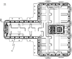
도 1은 본 발명의 하나의 실시예에 따른 팩 하우징의 구조를 개략적으로 나타낸 모식도이다;
도 2는 도 1의 A 부위에 대한 단면도이다;
도 3 은 본 발명의 하나의 실시예에 따른 커버 부싱에 대한 구조를 나타내는 모식도이다;
도 4 는 본 발명의 하나의 실시예에 따른 실 부싱에 대한 구조를 나타내는 모식도이다;
도 5 는 종래의 베이스 플레이트의 팩 체결부들을 나타내는 모식도이다;
도 6은 도 1의 베이스 플레이트의 팩 체결부들을 나타내는 모식도이다;
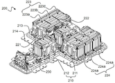
도 7에는 본 발명의 또 다른 실시예에 따른 전지팩의 베이스 플레이트 상에 전지모듈들이 탑재된 구조를 개략적으로 나타낸 모시도이다.1 is a schematic view schematically showing the structure of a pack housing according to an embodiment of the present invention;
Fig. 2 is a sectional view taken along the line A in Fig. 1; Fig.
3 is a schematic view showing a structure for a cover bushing according to one embodiment of the present invention;
4 is a schematic view showing a structure of an actual bushing according to one embodiment of the present invention;
5 is a schematic view showing the pack fastening portions of a conventional base plate;
Fig. 6 is a schematic view showing pack fastening portions of the base plate of Fig. 1; Fig.
7 is a schematic view illustrating a structure in which battery modules are mounted on a base plate of a battery pack according to another embodiment of the present invention.
이하에서는, 본 발명의 실시예에 따른 도면을 참조하여 설명하지만, 이는 본 발명의 더욱 용이한 이해를 위한 것으로, 본 발명의 범주가 그것에 의해 한정되는 것은 아니다.Hereinafter, embodiments of the present invention will be described with reference to the accompanying drawings, but the present invention is not limited by the scope of the present invention.
도 1에는 본 발명의 하나의 실시예에 따른 팩 하우징의 구조를 개략적으로 나타낸 모식도가 도시되어 있고, 도 2에는 도 1의 A 부위에 대한 단면도가 도시되어 있다.FIG. 1 is a schematic view schematically showing a structure of a pack housing according to an embodiment of the present invention, and FIG. 2 is a sectional view taken along a line A in FIG.
먼저, 도 1을 참조하면, 팩 하우징(100)은 전지모듈들(도 7 참조)이 상면에 탑재되어 고정되는 구조의 베이스 플레이트(110), 전지모듈들을 감싸면서 베이스 플레이트(110)의 외주변에 결합되는 구조의 팩 커버(120)를 포함하는 구조로 구성되어 있다.1, the pack housing 100 includes a
베이스 플레이트(110) 및 팩 커버(120)의 계면에는 도 2에 도시되어 있는 바와 같이, 팩 하우징(100)을 실링하는 가스켓 부재(130)가 장착되어 있고, 베이스 플레이트(110) 및 팩 커버(120)의 외주변들과 가스켓 부재(130) 부재에는 관통 구조의 체결공들과 커버 부싱(140) 및 실 부싱(150)이 구비되어 있는 복수의 팩 체결부들(160)이 형성되어 있고, 체결공들에 체결부재(161)가 삽입되어 상호 결합되는 구조로 구성되어 있다.2, a
커버 부싱(140) 및 실 부싱(150)은 가스켓 부재(130)가 직선 형태인 부위에 위치하는 팩 체결부들(160) 사이에 위치하고, 실 부싱(150)은 가스켓 부재(130)에 매립된 구조로 구성되어 있다.The
도 3에는 본 발명의 하나의 실시예에 따른 커버 부싱에 대한 구조를 나타내는 모식도가 도시되어 있고, 도 4에는 본 발명의 하나의 실시예에 따른 실 부싱에 대한 구조를 나타내는 모식도가 도시되어 있다.FIG. 3 is a schematic view showing a structure of a cover bushing according to an embodiment of the present invention, and FIG. 4 is a schematic view showing a structure of an actual bushing according to an embodiment of the present invention.
먼저, 도 3을 도 1 및 2와 함께 참조하면, 커버 부싱(140)은 금속 소재로 이루어져 있고, 베이스 플레이트(110) 및 팩 커버(120)의 외주변들과 가스켓 부재(130)들의 체결공들에 연통되는 관통구(141)가 천공되어 있는 구조로 구성되어 있다.Referring to FIG. 3, the
관통구(141)는 2개의 팩 체결부들(160)에 대응한 부위에 천공되어 있는 구조로서, 커버 부싱(140)은 2개의 팩 체결부들(160) 사이에서 금속 바 형태로 연결되어 있는 1 단위의 부재로 구성된다.The through
커버 부싱(140)은 도 2에 개시되어 있는 단면도를 기준으로 팩 커버(120)의 외주변 상에 장착되는 구조로 구성되며, 관통구(141)의 하단 측벽(142)이 베이스 플레이트(110) 방향으로 돌출 연장되어 있는 구조로 구성되어 있다.The
즉, 이러한 구조는 관통구(141)의 하단 측벽(142)이 팩 체결부들(160)에 삽입되는 구조로 구성되고, 체결부재(161)가 삽입됨으로써, 팩 커버(120)와 함께 가스켓 부재(130)를 압박하는 구조로 구성된다.That is, this structure has a structure in which the
다음으로 도 4를 도 2와 함께 참조하면, 실 부싱(150)은 커버 부싱(140)과 마찬가지로 금속 소재로 이루어져 있고, 베이스 플레이트(110) 및 팩 커버(120)의 외주변들과 가스켓 부재(130)들의 체결공들에 연통되는 관통구(151)가 천공되어 있는 구조로 구성되어 있다.Referring to FIG. 4 together with FIG. 2, the
또한, 실 부싱(150)은 도 2에 개시되어 있는 단면도를 기준으로 베이스 플레이트(110)와 팩 커버(120)의 사이에 장착되며, 관통구(151)는 2개의 팩 체결부들(160)에 대응한 부위에 천공되어 있는 구조로서, 실 부싱(150)은 2개의 팩 체결부들(160) 사이에서 금속 바 형태로 연결되어 있는 1 단위의 부재로 구성되어 있고, 가스켓 부재(130)의 내부에 매립되어 있는 구조로 구성되어 있다.The
도 5에는 종래의 베이스 플레이트의 팩 체결부들을 나타내는 모식도가 도시되어 있고, 도 6에는 도 1의 베이스 플레이트의 팩 체결부들을 나타내는 모식도가 도시되어 있다.FIG. 5 is a schematic view showing the pack fastening portions of the conventional base plate, and FIG. 6 is a schematic view showing the pack fastening portions of the base plate of FIG.
먼저, 도 5를 참조하면, 종래의 베이스 플레이트(11)의 경우, 베이스 플레이트(10)의 외주변을 따라 팩 커버와 결합되기 위하여 대략적으로 52개의 팩 체결부들(16)이 형성되어 있는 반면에, 도 6의 베이스 플레이트(110)의 경우, 커버 부싱(140) 및 실 부싱(150)의 구조상 종래의 베이스 플레이트(11)에 비하여 11개의 팩 체결부들(160)을 생략할 수 있다.5, in the case of the
따라서, 이러한 구조의 팩 하우징(100)은 베이스 플레이트(110)와 팩 커버(120) 사이에 가스켓 부재(130)를 포함하고, 상기 베이스 플레이트(110), 팩 커버(120) 및 가스켓 부재(130)에 포함되는 팩 체결부들(160)에 체결부재(161)가 삽입되어 상호 결합되는 구조를 가지며, 2개의 팩 체결부들(160) 사이에 커버 부싱(140) 및 실 부싱(150)이 상호 연결되어 있는 구조로 위치함으로써, 베이스 플레이트(110)와 팩 커버(120)의 결합 시 가해지는 압력으로 인하여 팩 하우징(100)의 밀봉성이 향상되고, 팩 하우징(100)의 결합을 위한 조립공정에 사용되는 부품 수를 최소화여 전반적인 조립 공정을 간소화 할 수 있고, 불량률을 감소시킬 수 있는 효과를 제공할 수 있다.Thus, the pack housing 100 of this structure includes a
도 7에는 본 발명의 또 다른 실시예에 따른 전지팩의 베이스 플레이트 상에 전지모듈들이 탑재된 구조를 개략적으로 나타낸 모식도가 도시되어 있다.7 is a schematic view showing a structure in which battery modules are mounted on a base plate of a battery pack according to another embodiment of the present invention.
도 7을 참조하면, 베이스 플레이트(210)는 평면상으로 각각 직사각형 구조로 이루어진 제 1 플레이트(211) 및 제 2 플레이트(212)로 구성되어 있으며, 제 2 플레이트(212)는 제 1 플레이트(211)의 외주변들 중에서 상대적으로 긴 길이를 갖는 일측 외주변의 중앙 부위에 연결되어 있다.7, the
베이스 플레이트(210)의 외주변에는 체결부재를 통해 커버 부재와 결합되는 복수의 제 1 체결공(213)과 전지팩(200)을 디바이스에 장착 및 고정하기 위한 복수의 제 2 체결공(214)이 형성되어 있다.A plurality of first fastening holes 213 are formed on the outer circumference of the
전지모듈군들(221, 222, 223, 224)은 전지셀들의 배열 방향이 제 1 플레이트(211)에 대한 제 2 플레이트(212)의 연결 방향에 수직인 제 1 전지모듈군(221)과 제 2 전지모듈군(222), 및 전지셀들의 배열 방향이 제 1 플레이트(211)에 대한 제 2 플레이트(212)의 연결 방향에 평행한 제 3 전지모듈군(223)과 제 4 전지모듈군(224)으로 구성되어 있다.The
제 1 전지모듈군(221)은 제 2 플레이트(212)의 상에 탑재되어 있고, 제 2 전지모듈군(222)은 제 1 전지모듈군(221)에 대향하는 위치에서 제 1 플레이트(211) 상에 탑재되어 있다.The first
제 3 전지모듈군(223)과 제 4 전지모듈군(224)은 제 2 전지모듈군(222)의 양측에 상호 분리 배열된 상태로, 제 1 플레이트(211)의 양측 단부에 각각 탑재되어 있다.The third
제 1 전지모듈군(221)과 제 2 전지모듈군(222)은 하나의 전지모듈로 이루어져 있으며, 제 3 전지모듈군(223)과 제 4 전지모듈군(224)은 각각 3개의 전지모듈들(223a, 223b, 223c, 224a, 224b, 124c)이 인접 배열되어 이루어진 전지모듈 어셈블리로 구성되어 있다.The first
본 발명이 속한 분야에서 통상의 지식을 가진 자라면 상기 내용을 바탕으로 본 발명의 범주내에서 다양한 응용 및 변형을 수행하는 것이 가능할 것이다.It will be understood by those skilled in the art that various changes in form and details may be made therein without departing from the spirit and scope of the invention as defined by the appended claims.
Claims (24)
전지모듈들이 상면에 탑재되어 고정되는 구조의 베이스 플레이트(base plate);
상기 전지모듈들을 감싸면서 베이스 플레이트의 외주변에 결합되는 구조의 팩 커버(pack cover); 및
상기 베이스 플레이트 및 팩 커버 사이의 계면에 장착되어 팩 하우징을 실링하는 가스켓 부재(gasket member);
를 포함하며,
상기 베이스 플레이트 및 팩 커버의 외주변들과 가스켓 부재에는 관통 구조의 체결공들과 커버 부싱(cover bushing) 및 실 부싱(seal bushing)이 구비되어 있는 복수의 팩 체결부들이 형성되어 있어서, 상기 체결공들에 체결부재가 삽입되어 상호 결합되며,
적어도 둘 이상의 팩 체결부들 사이에서, 이웃한 커버 부싱들 및 이웃한 실 부싱들 중의 적어도 하나는 상호 연결되어 있는 것을 특징으로 하는 팩 하우징.A pack housing for manufacturing a battery pack including at least two battery modules,
A base plate having a structure in which battery modules are mounted and fixed on an upper surface;
A pack cover configured to surround the battery modules and to be coupled to an outer periphery of the base plate; And
A gasket member mounted on an interface between the base plate and the pack cover to seal the pack housing;
/ RTI >
The outer periphery of the base plate and the pack cover and the gasket member are formed with a plurality of pack fastening portions having through-holes, a cover bushing, and a seal bushing, The fastening members are inserted into the balls and coupled with each other,
And at least one of the adjacent cover bushings and the neighboring seal bushings are interconnected between at least two of the pack fasteners.
상기 제 2 전지모듈 집합체는, 제 1 전지모듈 집합체의 제 2 전지모듈군의 양측에 상호 분리 배열된 상태로, 제 1 플레이트 상에 각각 탑재되어 있는 제 3 전지모듈군과 제 4 전지모듈군으로 구성되어 있는 것을 특징으로 하는 전지팩.18. The battery module assembly according to claim 17, wherein the first battery module assembly includes: a first battery module group mounted on a second plate; a second battery module group mounted on the first plate at a position facing the first battery module group; 2 battery modules;
The second battery module assembly may include a third battery module group and a fourth battery module group respectively mounted on the first plate in a state where the second battery module assembly is arranged on both sides of the second battery module group of the first battery module assembly And the battery pack (10).
Priority Applications (1)
| Application Number | Priority Date | Filing Date | Title |
|---|---|---|---|
| KR1020150171917A KR102066911B1 (en) | 2015-12-04 | 2015-12-04 | Pack Housing Having gasket Member and Battery Pack Containing the Same |
Applications Claiming Priority (1)
| Application Number | Priority Date | Filing Date | Title |
|---|---|---|---|
| KR1020150171917A KR102066911B1 (en) | 2015-12-04 | 2015-12-04 | Pack Housing Having gasket Member and Battery Pack Containing the Same |
Publications (2)
| Publication Number | Publication Date |
|---|---|
| KR20170065764A true KR20170065764A (en) | 2017-06-14 |
| KR102066911B1 KR102066911B1 (en) | 2020-01-16 |
Family
ID=59218042
Family Applications (1)
| Application Number | Title | Priority Date | Filing Date |
|---|---|---|---|
| KR1020150171917A KR102066911B1 (en) | 2015-12-04 | 2015-12-04 | Pack Housing Having gasket Member and Battery Pack Containing the Same |
Country Status (1)
| Country | Link |
|---|---|
| KR (1) | KR102066911B1 (en) |
Cited By (12)
| Publication number | Priority date | Publication date | Assignee | Title |
|---|---|---|---|---|
| US10483510B2 (en) | 2017-05-16 | 2019-11-19 | Shape Corp. | Polarized battery tray for a vehicle |
| US10632857B2 (en) | 2016-08-17 | 2020-04-28 | Shape Corp. | Battery support and protection structure for a vehicle |
| US10661646B2 (en) | 2017-10-04 | 2020-05-26 | Shape Corp. | Battery tray floor assembly for electric vehicles |
| US10886513B2 (en) | 2017-05-16 | 2021-01-05 | Shape Corp. | Vehicle battery tray having tub-based integration |
| KR20210054789A (en) | 2019-11-06 | 2021-05-14 | 주식회사 엘지화학 | Gasket Having Non-Welding Stopper and Battery Pack Containing the Same |
| KR20210088173A (en) | 2020-01-06 | 2021-07-14 | 주식회사 엘지에너지솔루션 | Apparatus And Method For Classifying Cylindrical battery cell |
| US11088412B2 (en) | 2017-09-13 | 2021-08-10 | Shape Corp. | Vehicle battery tray with tubular peripheral wall |
| KR20210109180A (en) | 2020-02-27 | 2021-09-06 | 주식회사 엘지에너지솔루션 | Battery pack case with improved electromagnetic wave shielding performance and battery pack including the same |
| US11155150B2 (en) | 2018-03-01 | 2021-10-26 | Shape Corp. | Cooling system integrated with vehicle battery tray |
| US11211656B2 (en) | 2017-05-16 | 2021-12-28 | Shape Corp. | Vehicle battery tray with integrated battery retention and support feature |
| US11214137B2 (en) | 2017-01-04 | 2022-01-04 | Shape Corp. | Vehicle battery tray structure with nodal modularity |
| US11688910B2 (en) | 2018-03-15 | 2023-06-27 | Shape Corp. | Vehicle battery tray having tub-based component |
Citations (6)
| Publication number | Priority date | Publication date | Assignee | Title |
|---|---|---|---|---|
| KR20100003138A (en) * | 2008-06-30 | 2010-01-07 | 주식회사 엘지화학 | Battery mounting system |
| KR20120030014A (en) * | 2010-09-16 | 2012-03-27 | 가부시키가이샤 리튬 에너지 재팬 | Battery pack and electrically powered vehicle provided with the same |
| KR20120033181A (en) * | 2010-09-29 | 2012-04-06 | 현대자동차주식회사 | Structure for mounting high voltage battery in vehicle |
| KR20120047984A (en) * | 2010-01-15 | 2012-05-14 | 미쯔비시 지도샤 고교 가부시끼가이샤 | Battery case for vehicle |
| KR20130107790A (en) * | 2012-03-23 | 2013-10-02 | 삼성에스디아이 주식회사 | Battery pack |
| JP2014194907A (en) * | 2013-03-29 | 2014-10-09 | Denso Corp | Battery pack |
-
2015
- 2015-12-04 KR KR1020150171917A patent/KR102066911B1/en active IP Right Grant
Patent Citations (6)
| Publication number | Priority date | Publication date | Assignee | Title |
|---|---|---|---|---|
| KR20100003138A (en) * | 2008-06-30 | 2010-01-07 | 주식회사 엘지화학 | Battery mounting system |
| KR20120047984A (en) * | 2010-01-15 | 2012-05-14 | 미쯔비시 지도샤 고교 가부시끼가이샤 | Battery case for vehicle |
| KR20120030014A (en) * | 2010-09-16 | 2012-03-27 | 가부시키가이샤 리튬 에너지 재팬 | Battery pack and electrically powered vehicle provided with the same |
| KR20120033181A (en) * | 2010-09-29 | 2012-04-06 | 현대자동차주식회사 | Structure for mounting high voltage battery in vehicle |
| KR20130107790A (en) * | 2012-03-23 | 2013-10-02 | 삼성에스디아이 주식회사 | Battery pack |
| JP2014194907A (en) * | 2013-03-29 | 2014-10-09 | Denso Corp | Battery pack |
Cited By (21)
| Publication number | Priority date | Publication date | Assignee | Title |
|---|---|---|---|---|
| US10632857B2 (en) | 2016-08-17 | 2020-04-28 | Shape Corp. | Battery support and protection structure for a vehicle |
| US11273697B2 (en) | 2016-08-17 | 2022-03-15 | Shape Corp. | Battery support and protection structure for a vehicle |
| US11660950B2 (en) | 2016-08-17 | 2023-05-30 | Shape Corp. | Battery support and protection structure for a vehicle |
| US11214137B2 (en) | 2017-01-04 | 2022-01-04 | Shape Corp. | Vehicle battery tray structure with nodal modularity |
| US11211656B2 (en) | 2017-05-16 | 2021-12-28 | Shape Corp. | Vehicle battery tray with integrated battery retention and support feature |
| US10886513B2 (en) | 2017-05-16 | 2021-01-05 | Shape Corp. | Vehicle battery tray having tub-based integration |
| US10483510B2 (en) | 2017-05-16 | 2019-11-19 | Shape Corp. | Polarized battery tray for a vehicle |
| US11691493B2 (en) | 2017-05-16 | 2023-07-04 | Shape Corp. | Vehicle battery tray having tub-based component |
| US11088412B2 (en) | 2017-09-13 | 2021-08-10 | Shape Corp. | Vehicle battery tray with tubular peripheral wall |
| US11787278B2 (en) | 2017-10-04 | 2023-10-17 | Shape Corp. | Battery tray floor assembly for electric vehicles |
| US10960748B2 (en) | 2017-10-04 | 2021-03-30 | Shape Corp. | Battery tray floor assembly for electric vehicles |
| US11267327B2 (en) | 2017-10-04 | 2022-03-08 | Shape Corp. | Battery tray floor assembly for electric vehicles |
| US10661646B2 (en) | 2017-10-04 | 2020-05-26 | Shape Corp. | Battery tray floor assembly for electric vehicles |
| US11155150B2 (en) | 2018-03-01 | 2021-10-26 | Shape Corp. | Cooling system integrated with vehicle battery tray |
| US11688910B2 (en) | 2018-03-15 | 2023-06-27 | Shape Corp. | Vehicle battery tray having tub-based component |
| KR20210054789A (en) | 2019-11-06 | 2021-05-14 | 주식회사 엘지화학 | Gasket Having Non-Welding Stopper and Battery Pack Containing the Same |
| JP2022530975A (en) * | 2020-01-06 | 2022-07-05 | エルジー エナジー ソリューション リミテッド | Cylindrical battery cell classification device and classification method using this |
| WO2021141285A1 (en) | 2020-01-06 | 2021-07-15 | 주식회사 엘지에너지솔루션 | Classification device for cylindrical battery cells, and classification method using same |
| KR20210088173A (en) | 2020-01-06 | 2021-07-14 | 주식회사 엘지에너지솔루션 | Apparatus And Method For Classifying Cylindrical battery cell |
| US11865587B2 (en) | 2020-01-06 | 2024-01-09 | Lg Energy Solution, Ltd. | Cylindrical battery cell sorting apparatus and sorting method using the same |
| KR20210109180A (en) | 2020-02-27 | 2021-09-06 | 주식회사 엘지에너지솔루션 | Battery pack case with improved electromagnetic wave shielding performance and battery pack including the same |
Also Published As
| Publication number | Publication date |
|---|---|
| KR102066911B1 (en) | 2020-01-16 |
Similar Documents
| Publication | Publication Date | Title |
|---|---|---|
| KR102066911B1 (en) | Pack Housing Having gasket Member and Battery Pack Containing the Same | |
| KR101636378B1 (en) | Module Housing for Unit Module Having Heat Radiation Structure and Battery Module Comprising the Same | |
| US10522803B2 (en) | Battery pack including coupling member having assembling guide function | |
| KR101769577B1 (en) | Battery Pack Having Hold Down Bracket | |
| KR20170085665A (en) | Battery Pack Having Two Stage Battery Modules | |
| KR102072220B1 (en) | Battery Pack Capable of Minimizing Space for Mounting to Device | |
| KR20140141825A (en) | Secondary Battery and Battery Module Having the Same | |
| KR20170065771A (en) | Battery Pack Comprising Battery Modules Having Battery Cells Arranged in Different Directions | |
| US20180254467A1 (en) | Pouch type of battery cell having unit electrode where a plurality of electrode tabs are formed | |
| KR20170084522A (en) | Battery Pack Having Side Cooling Type Cooling Member | |
| KR102101905B1 (en) | Battery Pack Having Multi-Stage Battery Modules | |
| KR101764841B1 (en) | Electrode Assembly of Incline Structure and Battery Cell Employed with the Same | |
| KR101750482B1 (en) | Method for Air Tightness Test of Battery Pack | |
| KR20170048804A (en) | Battery Pack Including Static Guide Member | |
| KR20170085675A (en) | Battery Pack Having Battery Modules of Symmetric Structure | |
| KR20160087999A (en) | Bus Bar Assembly Having Low Contact Resistance and Battery Module Including the Same | |
| KR20180065096A (en) | Battery Module Comprising Cell Frames of Standardized Structure | |
| KR101511950B1 (en) | Battery Module Containing LED Element On PCB | |
| KR20170021000A (en) | Electrode Assembly of Irregular Structure Comprising Unit Cells with Different Capacity and Size and Battery Cell Having the Same | |
| KR102092114B1 (en) | Battery Pack Having Battery Cells Integrally Formed in Perpendicular Array | |
| KR102082386B1 (en) | Battery Module Having Structure for Dispersing Load in Z-Axis Direction | |
| KR101797692B1 (en) | Jig for Assembling Secondary Battery Pack and Secondary Battery Pack Manufactured Using the Same | |
| KR20200072185A (en) | Storage case for battery cell and storage device including the same | |
| KR101779947B1 (en) | Battery Module Having Volage Sensing Part Comprising Anti-Condensation Structure | |
| KR101839403B1 (en) | Jig for Aligning Cooling Pipes |
Legal Events
| Date | Code | Title | Description |
|---|---|---|---|
| A201 | Request for examination | ||
| E902 | Notification of reason for refusal | ||
| E701 | Decision to grant or registration of patent right |