KR20170056464A - Filter element and manufacturing method thereof - Google Patents
Filter element and manufacturing method thereof Download PDFInfo
- Publication number
- KR20170056464A KR20170056464A KR1020160150604A KR20160150604A KR20170056464A KR 20170056464 A KR20170056464 A KR 20170056464A KR 1020160150604 A KR1020160150604 A KR 1020160150604A KR 20160150604 A KR20160150604 A KR 20160150604A KR 20170056464 A KR20170056464 A KR 20170056464A
- Authority
- KR
- South Korea
- Prior art keywords
- size
- particles
- filtration zone
- zone
- filtration
- Prior art date
Links
Images

Classifications
-
- B—PERFORMING OPERATIONS; TRANSPORTING
- B01—PHYSICAL OR CHEMICAL PROCESSES OR APPARATUS IN GENERAL
- B01D—SEPARATION
- B01D53/00—Separation of gases or vapours; Recovering vapours of volatile solvents from gases; Chemical or biological purification of waste gases, e.g. engine exhaust gases, smoke, fumes, flue gases, aerosols
- B01D53/02—Separation of gases or vapours; Recovering vapours of volatile solvents from gases; Chemical or biological purification of waste gases, e.g. engine exhaust gases, smoke, fumes, flue gases, aerosols by adsorption, e.g. preparative gas chromatography
- B01D53/04—Separation of gases or vapours; Recovering vapours of volatile solvents from gases; Chemical or biological purification of waste gases, e.g. engine exhaust gases, smoke, fumes, flue gases, aerosols by adsorption, e.g. preparative gas chromatography with stationary adsorbents
- B01D53/0407—Constructional details of adsorbing systems
- B01D53/0431—Beds with radial gas flow
-
- B—PERFORMING OPERATIONS; TRANSPORTING
- B01—PHYSICAL OR CHEMICAL PROCESSES OR APPARATUS IN GENERAL
- B01D—SEPARATION
- B01D15/00—Separating processes involving the treatment of liquids with solid sorbents; Apparatus therefor
- B01D15/08—Selective adsorption, e.g. chromatography
-
- B—PERFORMING OPERATIONS; TRANSPORTING
- B01—PHYSICAL OR CHEMICAL PROCESSES OR APPARATUS IN GENERAL
- B01D—SEPARATION
- B01D39/00—Filtering material for liquid or gaseous fluids
- B01D39/14—Other self-supporting filtering material ; Other filtering material
- B01D39/20—Other self-supporting filtering material ; Other filtering material of inorganic material, e.g. asbestos paper, metallic filtering material of non-woven wires
- B01D39/2055—Carbonaceous material
- B01D39/2058—Carbonaceous material the material being particulate
- B01D39/2062—Bonded, e.g. activated carbon blocks
-
- B—PERFORMING OPERATIONS; TRANSPORTING
- B01—PHYSICAL OR CHEMICAL PROCESSES OR APPARATUS IN GENERAL
- B01D—SEPARATION
- B01D2101/00—Types of filters having loose filtering material
- B01D2101/005—Types of filters having loose filtering material with a binder between the individual particles or fibres
-
- B—PERFORMING OPERATIONS; TRANSPORTING
- B01—PHYSICAL OR CHEMICAL PROCESSES OR APPARATUS IN GENERAL
- B01D—SEPARATION
- B01D2239/00—Aspects relating to filtering material for liquid or gaseous fluids
- B01D2239/04—Additives and treatments of the filtering material
- B01D2239/0407—Additives and treatments of the filtering material comprising particulate additives, e.g. adsorbents
-
- B—PERFORMING OPERATIONS; TRANSPORTING
- B01—PHYSICAL OR CHEMICAL PROCESSES OR APPARATUS IN GENERAL
- B01D—SEPARATION
- B01D2239/00—Aspects relating to filtering material for liquid or gaseous fluids
- B01D2239/06—Filter cloth, e.g. knitted, woven non-woven; self-supported material
- B01D2239/065—More than one layer present in the filtering material
-
- B—PERFORMING OPERATIONS; TRANSPORTING
- B01—PHYSICAL OR CHEMICAL PROCESSES OR APPARATUS IN GENERAL
- B01D—SEPARATION
- B01D2239/00—Aspects relating to filtering material for liquid or gaseous fluids
- B01D2239/08—Special characteristics of binders
-
- B—PERFORMING OPERATIONS; TRANSPORTING
- B01—PHYSICAL OR CHEMICAL PROCESSES OR APPARATUS IN GENERAL
- B01D—SEPARATION
- B01D2239/00—Aspects relating to filtering material for liquid or gaseous fluids
- B01D2239/08—Special characteristics of binders
- B01D2239/086—Binders between particles or fibres
-
- B—PERFORMING OPERATIONS; TRANSPORTING
- B01—PHYSICAL OR CHEMICAL PROCESSES OR APPARATUS IN GENERAL
- B01D—SEPARATION
- B01D2239/00—Aspects relating to filtering material for liquid or gaseous fluids
- B01D2239/10—Filtering material manufacturing
-
- B—PERFORMING OPERATIONS; TRANSPORTING
- B01—PHYSICAL OR CHEMICAL PROCESSES OR APPARATUS IN GENERAL
- B01D—SEPARATION
- B01D2253/00—Adsorbents used in seperation treatment of gases and vapours
- B01D2253/10—Inorganic adsorbents
- B01D2253/102—Carbon
-
- B—PERFORMING OPERATIONS; TRANSPORTING
- B01—PHYSICAL OR CHEMICAL PROCESSES OR APPARATUS IN GENERAL
- B01D—SEPARATION
- B01D2253/00—Adsorbents used in seperation treatment of gases and vapours
- B01D2253/30—Physical properties of adsorbents
- B01D2253/302—Dimensions
- B01D2253/304—Linear dimensions, e.g. particle shape, diameter
Abstract
Description
본 발명은 유체 내의 미립자 물질을 여과하기 위한 필터 엘리먼트, 특히 다양한 크기의 미립자 물질을 여과하도록 구성된 복수의 여과 구역을 포함하는 탄소 블록 필터 엘리먼트, 및 그의 제조 방법에 관한 것이다.The present invention relates to a filter element for filtering particulate matter in a fluid, in particular a carbon block filter element comprising a plurality of filtration zones configured to filter particulate matter of various sizes, and a method of manufacturing the same.
여과를 위한 탄소 블록은 활성 탄소 입자 및 적절한 바인더로부터 제조된다. 선행 기술에서 탄소 블록의 제조 방법은 탄소 블록의 무압력 소결 및 압력 소결을 포함한다. 어떠한 방법을 사용하는가에 상관없이, 수득된 탄소 블록의 구조는 균일하다, 즉, 활성 탄소 입자 사이에서 형성된 기공은 기공의 크기보다 더 작은 모든 미립자 물질(particulate materials)을 여과하는 실질적으로 동일한 크기이다.The carbon block for filtration is made from activated carbon particles and suitable binders. In the prior art, methods of making carbon blocks include pressureless sintering and pressure sintering of carbon blocks. Regardless of the method used, the structure of the resulting carbon block is uniform, i.e. the pores formed between the activated carbon particles are of substantially the same size to filter out all particulate materials smaller than the pore size .
작은 활성 탄소 입자의 크기는 고 염소 흡수능을 갖는 탄소 블록을 제조하기 위하여 선택될 수 있다. 그러나 활성 탄소 입자가 작은 크기일 때, 탄소 블록의 양측에 걸친 압력 강하는 증가하며 탄소 블록 내의 입자 간 기공은 유체 내의 미립자 물질에 의해 용이하게 막힌다. 작은 크기의 표면 입자 간 기공은 아주 작은 미립자 물질이 기공을 막히게 하여 유체의 흐름을 차단하는 이러한 타입의 여과는 표면 여과라고 한다. 이러한 타입의 여과에서, 탄소 블록의 내부에 여전히 많은 활성 탄소 입자가 염소를 흡수하기 위하여 완전히 이용되지 않았지만, 처리될 유체는 이들 활성 탄소 입자와 접촉할 수 없다.The size of the small activated carbon particles can be selected to produce a carbon block with high chlorine absorption capacity. However, when the activated carbon particles are small in size, the pressure drop across both sides of the carbon block increases and the interstitial pores in the carbon block are easily clogged by particulate matter in the fluid. This small type of surface-to-surface particle pore is called surface filtration, because very small particulate matter clogs the pores and blocks fluid flow. In this type of filtration, many activated carbon particles are still not fully utilized to absorb chlorine inside the carbon block, but the fluid to be treated can not contact these activated carbon particles.
또 다른 측면에서, 표면 입자 간 기공이 막히는 것을 방지하기 위하여, 특정한 탄소 블록은 더 큰 크기의 활성 탄소 입자로 제조된다. 그러나 더 큰 크기의 활성 탄소 입자는 탄소 블록의 양측에 걸친 압력을 현저하게 강하하도록 야기하여, 탄소 블록을 통해 유동하는 유체의 유속을 유의하게 증가시키며, 즉, 탄소 블록 내의 유체의 체류 시간(retention time)을 유의하게 감소시키며, 따라서 유체 내의 미립자 물질을 위한 탄소 블록 내의 활성 탄소 입자의 흡수능은 심하게 영향을 받는다. 게다가, 활성 탄소 입자의 크기가 증가함에 따라, 이를 통해 더 작은 크기(예컨대 1㎛ 미만의 크기)의 미립자 물질의 통과를 허용하는, 탄소 블록 내의 입자 간 기공의 크기도 또한 증가할 것이다. 특정 탄소 블록은 심지어 5㎛ 초과 크기의 미립자 물질만을 여과할 수 있다.In another aspect, certain carbon blocks are made of activated carbon particles of larger size to prevent clogging of pores between the surface particles. However, larger size activated carbon particles cause the pressure across both sides of the carbon block to drop significantly, significantly increasing the flow rate of the fluid flowing through the carbon block, i.e., the retention time of the fluid in the carbon block ), And thus the ability of the activated carbon particles in the carbon block for particulate matter in the fluid to be severely affected. In addition, as the size of the activated carbon particles increases, the size of the intergranular pores in the carbon block will also increase, thereby allowing the passage of particulate material through a smaller size (e.g., less than 1 micron size). Certain carbon blocks can filter only particulate matter of size exceeding 5 mu m.
그러므로 현재 높은 여과능(더 작은 크기의 미립자 물질을 여과할 수 있음) 및 높은 흡수능(미립자 물질을 흡수하기 위하여 탄소 블록 내부에서 활성 탄소 입자를 완전하게 사용하도록 함) 양자를 갖는 필터 엘리먼트에 대한 필요가 있다.Therefore, there is a need for a filter element with both a high filtration capacity (which can filter smaller particle size particulate matter) and a higher sorption capacity (to use activated carbon particles completely within the carbon block to absorb particulate matter) .
(발명의 요약)SUMMARY OF THE INVENTION [
상기 기술적인 문제점을 해결하기 위하여, 본 발명의 목적은 제1 여과 구역은 더 큰 입자 크기의 필터 물질(예컨대 활성 탄소)로 구성되며, 유체의 유동 방향의 상류에 위치하고, 제1 여과 구역은 더 큰 크기의 미립자 물질을 여과하기 위하여 사용되며; 제2 여과 구역은 더 작은 입자 크기의 필터 물질로 구성되며 유체의 유동 방향의 하류에 위치하고, 제2 여과 구역은 더 작은 크기의 미립자 물질을 여과하기 위하여 사용되며 또한 미립자 물질을 흡수할 수 있고; 제1 여과 구역과 제2 여과 구역의 사이에 더 큰 크기의 필터 물질 및 더 작은 크기의 필터 물질의 혼합물로 구성된 전이 구역이 존재하는, 과립 물질을 소결하여 형성된, 탄소 블록과 같은 필터 엘리먼트를 제공하는 것이다. 이러한 필터 엘리먼트는 더 작은 크기의 필터 미립자 물질을 여과할 수 있고 미립자 물질을 흡수하기 위해 필터 엘리먼트의 내부 깊숙이 필터 물질을 완전히 이용할 수 있다. 즉 높은 여과능 및 높은 흡수능 양자를 가질 수 있다. 더욱이, 이러한 필터 엘리먼트는 미립자 물질에 의해 막히는 경향이 적으며 따라서 긴 수명을 갖는다.In order to solve the above technical problem, it is an object of the present invention to provide a filtration device in which the first filtration zone is composed of a larger particle size filter material (for example, activated carbon) and is located upstream of the flow direction of the fluid, Used to filter large size particulate matter; The second filtration zone is comprised of a smaller particle size filter material and is located downstream of the flow direction of the fluid and the second filtration zone is used to filter smaller size particulate matter and is also capable of absorbing particulate matter; There is provided a filter element, such as a carbon block, formed by sintering a granular material in which there is a transition zone between a first filtration zone and a second filtration zone, the transition zone consisting of a mixture of a larger size filter substance and a smaller size filter substance . Such a filter element can filter smaller size filter particulate material and fully utilize the filter material deep inside the filter element to absorb the particulate material. That is, both of high filtration ability and high absorption capacity. Moreover, such filter elements are less prone to clogging by particulate matter and thus have a long life.
특히, 본 발명은 제1 여과 구역 및 제2 여과 구역을 포함하는, 유체 내의 미립자 물질을 정화하기 위한 필터 엘리먼트를 제공하는 것으로, 제1 여과 구역은 제1 크기의 입자와 그 사이에 형성된 제1 크기의 입자 간 기공의 집합(collection)을 포함하며, 제2 여과 구역은 제2 크기의 입자와 그 사이에 형성된 제2 크기의 입자 간 기공의 집합을 포함하며, 제1 크기의 입자 간 기공이 제2 크기의 입자 간 기공의 기공 크기보다 더 큰 기공 크기를 갖도록 제1 크기의 입자의 평균 크기가 제2 크기의 입자의 평균 크기보다 더 크고; 필터 엘리먼트는 제1 여과 구역과 제2 여과 구역을 상호 연결하는 전이 구역을 더 포함하며, 전이 구역은 제1 여과 구역에서 제2 여과 구역으로의 방향으로 보았을 때, 기공 크기가 제1 크기의 입자 간 기공의 기공 크기에서 제2 크기의 입자 간 기공의 기공 크기로 점진적으로 감소하는 입자 간 기공을 갖도록 하는 방식으로 제1 크기의 입자 및 제2 크기의 입자의 혼합물로부터 형성된다.In particular, the present invention provides a filter element for purifying particulate matter in a fluid, comprising a first filtration zone and a second filtration zone, wherein the first filtration zone comprises a first size of particles and a first Wherein the second filtration zone comprises a collection of pores of a second size between particles of a second size and a second size formed therebetween, Wherein the average size of the first size particles is greater than the average size of the second size particles to have a pore size greater than the pore size of the second size intergranular pores; The filter element further comprises a transition zone interconnecting the first filtration zone and the second filtration zone, wherein the transition zone has a pore size of at least about < RTI ID = 0.0 > Is formed from a mixture of particles of a first size and particles of a second size in such a manner that they have intergranular pores which gradually decrease from the pore size of the interstitial pores to the pore size of the intergranular pores of the second size.
본 발명의 필터 엘리먼트의 한 실시양태에서, 전이 구역은 제1 여과 구역에서 제2 여과 구역으로의 방향으로 보았을 때 점진적으로 감소하는 함량의 제1 크기의 입자 및 점진적으로 증가하는 함량의 제2 크기의 입자를 갖는다. In one embodiment of the filter element of the present invention, the transition zone comprises a gradually decreasing amount of particles of first size and a second increasing amount of particles of increasing magnitude when viewed in a direction from the first filtration zone to the second filtration zone, Of particles.
본 발명의 필터 엘리먼트의 한 실시양태에서, 제1 여과 구역은 유체의 유동 방향으로 제2 여과 구역의 상류에 위치한다. In one embodiment of the filter element of the present invention, the first filtration zone is located upstream of the second filtration zone in the flow direction of the fluid.
본 발명의 필터 엘리먼트의 한 실시양태에서, 제1 크기의 입자 및 제2 크기의 입자 양자는 활성 탄소 입자로부터 선택된다.In one embodiment of the filter element of the present invention, both the particles of the first size and the particles of the second size are selected from activated carbon particles.
본 발명의 필터 엘리먼트의 한 실시양태에서, 활성 탄소 입자는 활성 탄소 입자를 둘러싸는 바인더로서 폴리에틸렌 입자를 포함한다. 바람직하게는, 폴리에틸렌은 초고분자량 폴리에틸렌(UHMWPE)이다. 더 바람직하게는, 초고분자량 폴리에틸렌은 1200ml/g 내지 4300ml/g 범위의 점도를 갖는다.In one embodiment of the filter element of the present invention, the activated carbon particles comprise polyethylene particles as a binder surrounding the activated carbon particles. Preferably, the polyethylene is ultra high molecular weight polyethylene (UHMWPE). More preferably, the ultra high molecular weight polyethylene has a viscosity ranging from 1200 ml / g to 4300 ml / g.
본 발명의 필터 엘리먼트의 한 실시양태에서, 제1 크기의 입자는 250㎛ 초과의 입자 크기를 가지며, 제2 크기의 입자는 60㎛ 내지 200㎛의 입자크기를 갖는다. 바람직하게는, 제1 여과 구역은 200㎛ 초과의 입자 크기를 갖는 미립자 물질을 여과하고 200㎛ 미만의 입자 크기를 갖는 미립자 물질이 제1 여과 구역을 투과 및/또는 통과하도록 구성되며, 전이 구역은 1㎛ 내지 200㎛의 입자 크기를 갖는 미립자 물질을 여과하도록 구성되고, 그리고 제2 여과 구역은 1㎛ 초과의 입자 크기를 갖는 미립자 물질을 여과하도록 구성된다.In one embodiment of the filter element of the present invention, the particles of the first size have a particle size of more than 250 mu m and the particles of the second size have a particle size of 60 mu m to 200 mu m. Preferably, the first filtration zone is configured to filter particulate matter having a particle size of greater than 200 microns and to allow particulate matter having a particle size of less than 200 microns to pass and / or pass through the first filtration zone, The first filtration zone is configured to filter particulate matter having a particle size of from 1 m to 200 m and the second filtration zone is configured to filter particulate matter having a particle size greater than 1 m.
본 발명의 필터 엘리먼트의 한 실시양태에서, 제1 여과 구역, 제2 여과 구역 및/또는 전이 구역은 미립자 물질, 특히 염소를 흡수할 수 있는 물질로 제조된다. 바람직하게는, 미립자 물질은 주로 제2 여과 구역에서 흡수된다.In one embodiment of the filter element of the present invention, the first filtration zone, the second filtration zone and / or the transition zone are made of a particulate material, in particular a material capable of absorbing chlorine. Preferably, the particulate material is primarily absorbed in the second filtration zone.
본 발명의 필터 엘리먼트의 한 실시양태에서, 필터 엘리먼트는 제1 여과 구역이 전이 구역을 둘러싸고 이어서 전이 구역이 제2 여과 구역을 둘러싸는 소결된 원통형 구조체로서 형성된다. 다시 말해서, 제1 여과 구역은 필터 엘리먼트의 외측에 근접하며, 제2 여과 구역은 필터 엘리먼트의 내측에 근접하고, 전이 구역은 제1 여과 구역 및 제2 여과 구역 사이에 위치한다.In one embodiment of the filter element of the present invention, the filter element is formed as a sintered cylindrical structure in which a first filtration zone surrounds the transition zone and a transition zone surrounds the second filtration zone. In other words, the first filtration zone is close to the outside of the filter element, the second filtration zone is close to the inside of the filter element, and the transition zone is between the first filtration zone and the second filtration zone.
본 발명의 또 다른 측면은 하기 단계를 포함하는 필터 엘리먼트의 제조 방법을 제공한다: 과립 물질을 수용하기 위한 캐비티를 갖고, 상기 캐비티를 제1 캐비티 및 제2 캐비티로 분할하기 위한 네트워크를 포함하는 몰드를 제공하는 단계; 제1 크기의 입자의 평균 크기는 제2 크기의 입자의 평균 크기보다 큰, 제1 크기의 입자 및 제2 크기의 입자로 각각 제1 캐비티 및 제2 캐비티를 충전하는 단계; 제1 크기의 입자 및 제2 크기의 입자가 서로를 향해 이동하도록 하여 제1 여과 구역과 제2 여과 구역을 상호 연결하는 전이 구역을 형성하도록 하는 방식으로 몰드로부터 네트워크를 제거하는 단계; 제1 크기의 입자와 그 사이에 형성된 제1 크기의 입자 간 기공을 포함하는 제1 여과 구역, 및 제2 크기의 입자와 그 사이에 형성된 제2 크기의 입자 간 기공을 포함하는 제2 여과 구역을 각기 형성하도록, 제1 크기의 입자 및 제2 크기의 입자를 적절한 온도에서 소결하는 단계를 포함하고, 상기 소결단계에서, 제1 크기의 입자 간 기공은 제2 크기의 입자 간 기공의 기공 크기보다 더 큰 기공 크기를 가지며, 전이 구역은 제1 여과 구역에서 제2 여과 구역으로의 방향으로 보았을 때, 기공 크기가 제1 크기의 입자 간 기공의 기공 크기에서 제2 크기의 입자 간 기공의 기공 크기로 점진적으로 감소하는 입자 간 기공을 갖도록 하는 방식으로 제1 크기의 입자 및 제2 크기의 입자의 혼합물을 소결하여 전이 구역이 형성된다. 바람직하게는, 상기 소결 온도는 170℃ 내지 220℃이다.Another aspect of the present invention provides a method of making a filter element comprising the steps of: providing a mold having a cavity for receiving granular material and a network for dividing the cavity into a first cavity and a second cavity, ; Filling the first cavity and the second cavity with a first size of particles and a second size of particles, respectively, wherein the average size of the first size of particles is larger than the average size of the second size of the particles; Removing the network from the mold in such a manner as to cause particles of a first size and particles of a second size to move toward each other to form a transition zone interconnecting the first filtration zone and the second filtration zone; A first filtration zone comprising particles of a first size and pores of a first size formed therebetween and a second filtration zone comprising pores of a second size and particles of a second size formed therebetween, Sintering the particles of the first size and the particles of the second size at an appropriate temperature so that the pores of the first size have a pore size of the pores of the second size, Wherein the transition zone has a pore size of at least one of a pore size of the intergranular pores of the first size and a pore size of the intergranular pores of the second size when viewed in the direction from the first filtration zone to the second filtration zone, The transition zone is formed by sintering a mixture of particles of a first size and particles of a second size in such a manner that they have progressively decreasing inter-particle pores in size. Preferably, the sintering temperature is from 170 캜 to 220 캜.
본 발명의 방법의 한 실시양태에 따라, 제1 여과 구역에서 제2 여과 구역으로의 방향으로 보았을 때, 전이 구역이 점진적으로 감소하는 함량의 제1 크기의 입자 및 점진적으로 증가하는 함량의 제2 크기의 입자를 갖도록 하는 방식으로 상기 소결 단계가 수행된다.According to one embodiment of the method of the invention, the transition zone has a gradually decreasing amount of first size particles and a second increasing amount of content of second, when viewed in the direction from the first filtration zone to the second filtration zone, The sintering step is carried out in such a manner as to have a size of particles.
본 발명의 방법의 한 실시양태에 따라, 제1 크기의 입자 및 제2 크기의 입자 양자는 활성 탄소 입자로부터 선택된다.According to one embodiment of the method of the present invention, both the particles of the first size and the particles of the second size are selected from activated carbon particles.
본 발명의 방법의 한 실시양태에 따라, 상기 활성 탄소 입자는 상기 활성 탄소 입자를 둘러싸는 바인더로서 폴리에틸렌 입자를 포함한다. 바람직하게는, 상기 폴리에틸렌은 초고분자량 폴리에틸렌이다. 더 바람직하게는, 상기 초고분자량 폴리에틸렌은 1200ml/g 내지 4300ml/g 범위의 점도를 갖는다.According to one embodiment of the method of the present invention, the activated carbon particles comprise polyethylene particles as a binder surrounding the activated carbon particles. Preferably, the polyethylene is ultra high molecular weight polyethylene. More preferably, the ultra high molecular weight polyethylene has a viscosity ranging from 1200 ml / g to 4300 ml / g.
본 발명의 방법의 한 실시양태에 따라, 제1 크기의 입자는 250㎛ 초과의 크기를 가지며, 제2 크기의 입자는 60㎛ 내지 200㎛의 크기를 갖는다. 바람직하게는, 상기 소결 단계는 제1 여과 구역이 200㎛ 초과의 입자 크기를 갖는 미립자 물질은 여과하고 200㎛ 미만의 입자 크기를 갖는 미립자 물질이 제1 여과 구역을 투과 및/또는 통과하도록 구성되며, 전이 구역은 1㎛ 내지 200㎛의 입자 크기를 갖는 미립자 물질을 여과하도록 구성되고, 그리고 제2 여과 구역은 1㎛ 초과의 입자 크기를 갖는 미립자 물질을 여과하도록 구성되는 방식으로 수행된다.According to one embodiment of the method of the present invention, the particles of the first size have a size of more than 250 mu m and the particles of the second size have a size of 60 mu m to 200 mu m. Preferably, the sintering step is such that the first filtration zone is configured to filter particulate material having a particle size greater than 200 microns and particulate material having a particle size less than 200 microns to pass and / or pass through the first filtration zone , The transition zone is configured to filter particulate matter having a particle size of from 1 mu m to 200 mu m, and the second filtration zone is configured to filter particulate matter having a particle size of greater than 1 mu m.
본 발명의 방법의 한 실시양태에 따라, 상기 몰드는 원통형 내벽, 원통형 외벽, 및 내벽의 직경보다 크지만 외벽의 직경보다 작은 직경을 갖는 원통형 네트워크를 갖는다. 바람직하게는, 네트워크 및 외벽은 제1 캐비티를 형성하고, 네트워크 및 내벽은 제2 캐비티를 형성한다.According to one embodiment of the method of the present invention, the mold has a cylindrical network having a cylindrical inner wall, a cylindrical outer wall, and a diameter larger than the diameter of the inner wall but smaller than the diameter of the outer wall. Preferably, the network and the outer wall form a first cavity, and the network and inner wall form a second cavity.
도 1은 본 발명의 실시양태에 따른 필터 엘리먼트의 구조체의 개략도이다.
도 2는 본 발명의 또 다른 실시양태에 따른 필터 엘리먼트의 단면도이다.
도 3은 본 발명의 실시양태에 따른 본 발명의 필터 엘리먼트를 제조하기 위한 금형의 개략도이다.1 is a schematic view of a structure of a filter element according to an embodiment of the present invention.
2 is a cross-sectional view of a filter element according to another embodiment of the present invention.
3 is a schematic view of a mold for manufacturing a filter element of the present invention in accordance with an embodiment of the present invention.
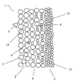
도 1은 본 발명의 실시양태에 따른 필터 엘리먼트(1)를 나타낸다. 이 실시양태에서, 필터 엘리먼트(1)는 탄소 블록이다. 즉, 이것은 활성 탄소 입자 및 적절한 바인더(예컨대 플라스틱 물질)로부터 형성된다. 그러나 본 발명의 필터 엘리먼트가 필터 매체, 예컨대 임의의 형태의 세라믹 블록, 소결된 PE 블록, 소결된 금속 블록, 등으로부터 형성될 수 있음은 통상의 기술자의 능력 내에 있을 것이다.Figure 1 shows a filter element 1 according to an embodiment of the invention. In this embodiment, the filter element 1 is a carbon block. That is, it is formed from activated carbon particles and a suitable binder (e.g., plastic material). It will be appreciated, however, that the filter element of the present invention may be formed from a filter medium, such as any form of ceramic block, sintered PE block, sintered metal block, or the like.
필터 엘리먼트(1)는 유체 유동 방향 F의 상류에 위치한 제1 여과 구역(2), 유체 유동 방향 F의 하류에 위치한 제2 여과 구역(3), 및 제1 여과 구역(2)과 제2 여과 구역(3)을 상호 연결하는 전이 구역(4)을 포함한다. 제1 여과 구역(2)은 제1 크기 입자의 집합을 포함한다. 이 실시양태에서, 제1 크기의 입자는 250㎛ 초과의 입자 크기를 갖는 큰 활성 탄소 입자(5)이다. 적절한 크기의 폴리에틸렌 입자가 큰 활성 탄소 입자(5)의 외부 표면의 적어도 일부분 상에 배치된다. 폴리에틸렌의 기능은 큰 활성 탄소 입자(5)가 함께 결합하여 제1 여과 구역(2)을 형성하도록 하기 위하여 큰 활성 탄소 입자(5) 사이에서 바인더로서 작용한다. 제1 크기의 입자 간 기공(14)은 큰 활성 탄소 입자(5) 사이에서 형성된다. 제1 여과 구역(2)은 200㎛ 초과의 입자 크기를 갖는 미립자 물질(6)은 여과하고, 즉 200㎛ 초과의 입자 크기를 갖는 미립자 물질은 제1 여과 구역(2)의 외부에서 차단될 것이며, 반면에 200㎛ 이하의 입자 크기를 갖는 미립자 물질은 제1 여과 구역(2)을 투과 및/또는 통과하도록 구성된다. The filter element 1 has a
제2 여과 구역(3)은 제2 크기의 입자의 집합을 포함한다. 이 실시양태에서, 제2 크기의 입자는 60㎛ 내지 250㎛의 입자 크기를 갖는 작은 활성 탄소 입자(13)로부터 형성된다. 작은 활성 탄소 입자(13)는 또한 작은 활성 탄소 입자(13)가 함께 결합하여 제2 여과 구역(3)을 형성하도록 하기 위하여 작은 활성 탄소 입자를 둘러싸는 바인더로서 작용하는 적절한 크기의 폴리에틸렌 입자를 갖는다. 제2 크기의 입자 간 기공(15)은 작은 활성 탄소 입자(13) 사이에서 형성된다. 제2 여과 구역(3)은 1㎛ 초과의 입자 크기를 갖는 미립자 물질을 여과하도록 구성된다. 초고분자량 폴리에틸렌, 특히 1200ml/g 내지 4300ml/g 범위의 점도를 갖는 초고분자량 폴리에틸렌이 배치된 외부 표면상에서의, 큰 활성 탄소 입자(5) 및 작은 활성 탄소 입자(13)는 더 우수한 여과 효과가 달성될 수 있음이 실험적으로 입증되었다.The second filtration zone (3) comprises a collection of particles of a second size. In this embodiment, the particles of the second size are formed from small activated
도 1에서 나타낸 바와 같이, 전이 구역(4)은 제1 여과 구역(2) 및 제2 여과 구역(3) 사이에 위치하며, 전이 구역(4) 내에 큰 활성 탄소 입자(5) 및 작은 활성 탄소 입자(13) 양자가 있다. 게다가, 전이 구역(4)은 유체 유동 방향 F에서 보았을 때 점진적으로 감소하는 함량의 큰 활성 탄소 입자(5) 및 점진적으로 증가하는 함량의 작은 활성 탄소 입자(13)를 갖도록 구성된다. 그러므로 제1 여과 구역(2)에서 제2 여과 구역(3)으로의 방향에서, 전이 구역(4)의 입자 사이에 형성된 입자 간 기공의 기공 크기는 점진적으로 감소한다, 즉 제1 크기의 입자 간 기공(14)의 기공 크기에서 출발하여 제2 크기의 입자 간 기공(15)의 기공 크기로 점진적으로 감소한다. 전이 구역(4)은 1㎛ 내지 200㎛의 입자 크기를 갖는 미립자 물질을 여과하도록 구성된다.1, the
200㎛ 초과의 입자 크기를 가지며 따라서 제1 여과 구역(2)의 외부에서 차단되는 미립자 물질은 제1 여과 구역(2)의 상류 표면에 유지되며 필터 엘리먼트(1)의 일부가 된다. 이들 미립자 물질은 더 큰 크기이며 그 사이에 더 큰 갭을 갖기 때문에, 여과될 유체는 차단됨이 없이 미립자 물질 사이의 이들 갭을 통해 원활하게 유동할 수 있다. 200㎛ 미만이지만 1㎛ 초과의 입자 크기를 갖는 미립자 물질은 제1 여과 구역(2)로 투과될 수 있다. 이 입자 크기의 미립자 물질은 제1 여과 구역(2)를 통과하여 전이 구역(4)에 도달될 수 있거나, 또는 제1 여과 구역(2)의 내부에 유지될 수 있다. 이들 미립자 물질은 여전히 큰 크기이므로, 전이 구역(4)의 내부 또는 제1 여과 구역(2)의 내부에서 이들이 유지될지라도, 유체는 미립자 물질 사이에서 형성된 갭을 통해 유동할 수 있다. 그러므로 제1 여과 구역(2)으로 투과하거나 또는 통과되는 이들 미립자 물질은 또한 필터 엘리먼트(1)의 일부가 되며 필터 매체로서의 기능을 한다.Particulate matter having a particle size of more than 200 μm and thus being blocked off from the
제2 여과 구역(3) 내의 활성 탄소 입자(13)는 더 작은 크기이며 따라서 입자 간 기공의 기공 크기가 더 작기 때문에, 제2 여과 구역(3)은 더 작은 입자 크기의 미립자 물질의 통과를 차단할 수 있다. 게다가, 제2 여과(3)는 또한 유체의 유속을 감소시키기 때문에, 탄소 블록 내의 유체의 체류 시간을 연장하여 충분한 시간 동안 유체 내의 미립자 물질과 탄소 블록 내의 활성 탄소 입자의 접촉을 허용한다.Since the activated
그러므로 본 발명의 원리는 표면 여과가 유체 유동 방향의 하류에 위치한 여과 구역 내에서만 발생하도록 제한하여, 상이한 크기의 미립자 물질의 구배 배열(gradient arrangement) 의해 달성된 심층 여과를 기초로 하며, 이에 의해 높은 여과능 및 높은 흡수능 양자를 갖는 필터 엘리먼트를 제조한다. 또한, 선행 기술의 필터 엘리먼트와는 달리, 본 발명의 필터 엘리먼트는 계층 구조체(hierarchical structure)는 아니지만, 입자 크기 및 입자 간 기공 크기의 관점에서 구배를 갖는 연속 구조체로서 구성된다. 본원에서 필터 엘리먼트(1)는 여과 구역(2), 전이 구역(4) 및 여과 구역(3)를 갖는 것으로 규정되지만, 통상의 기술자는 세 여과 구역 중의 각각의 두 인접 구역 간의 계면은 없음을 이해할 것이다. 그러므로 본 발명에 따라, 필터 엘리먼트(1)는, 큰 활성 탄소 입자(5)의 함량이 유체 유동 방향으로 점진적으로 감소하며, 한편 작은 활성 탄소 입자(13)의 함량은 유체 유동 방향으로 점진적으로 증가하는, 큰 활성 탄소 입자(5) 및 작은 활성 탄소 입자(13)를 포함하는 하나의 여과 구역으로서 이해될 수 있다. 이러한 구배 구조는 본 발명의 필터 엘리먼트(1)가 점점 막히는 경향 없이 다양한 크기의 미립자 물질을 더 잘 여과 및/또는 흡수할 수 있도록 하는 것을 가능하게 한다.The principle of the present invention therefore is based on deep filtration achieved by limiting the surface filtration to occur only in the filtration zone located downstream in the fluid flow direction and by gradient arrangement of different sized particulate materials, A filter element having both filterability and high absorption capacity is produced. Also, unlike the filter elements of the prior art, the filter elements of the present invention are not hierarchical structures, but are constructed as continuous structures with a gradient in terms of particle size and interparticle pore size. Although the filter element 1 is herein defined as having a
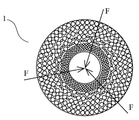
도 2는 본 발명의 또 다른 실시양태에 따른 필터 엘리먼트(1)를 나타낸다. 이 실시양태에서, 제1 여과 구역(2) 및 제2 여과 구역(3)은 양자가 원통형이며, 제1 여과 구역(2)은 전이 구역(4)을 둘러싸고 이어서 전이 구역(4)은 제2 여과 구역(3)을 둘러싼다. 다시 말해서, 제1 여과 구역(2)은 필터 엘리먼트(1)의 외측에 근접하고, 제2 여과 구역은 필터 엘리먼트(1)의 내측에 근접하며, 그리고 전이 구역(4)은 제1 여과 구역(2) 및 제2 여과 구역(3) 사이에 위치한다. 유체 유동 방향 F는 필터 엘리먼트의 외부에서 필터 엘리먼트의 내부이다. 통상의 기술자는 본 발명의 필터 엘리먼트가 원뿔형 구조, 블록 구조, 등과 같은 임의의 형상 및 임의의 크기로 형성될 수 있다는 것을 이해할 것이다.Figure 2 shows a filter element 1 according to another embodiment of the invention. In this embodiment, the
본 발명의 실시양태에 따른 도 2에 나타낸 바의 필터 엘리먼트(1)의 제조 방법은 하기에 기술된다. 통상의 기술자는 방법이 도 2에 나타낸 형태로 필터 엘리먼트를 제조하는 것으로 한정하는 것은 아니며, 다른 형상의 필터 엘리먼트의 제조가 필요할 때, 상응하는 형상의 금형을 사용하는 것도 수행할 것임을 이해할 것이다.The manufacturing method of the filter element 1 shown in Fig. 2 according to the embodiment of the present invention is described below. It will be appreciated by those of ordinary skill in the art that the method is not limited to fabricating the filter element in the form shown in FIG. 2 and that the use of a correspondingly shaped mold will also be performed when the production of filter elements of other shapes is desired.
도 2에 나타낸 바의 필터 엘리먼트(1)를 제조하기 위하여, 우선, 도 3에 나타낸 바의 과립 물질(granular materials)을 수용하기에 적당한 원통형 몰드(7)를 제공할 필요가 있다. 몰드(7)는 170℃ 내지 220℃의 소결 온도에서 안정한 물질로 제조될 수 있다. 몰드(7)는 동축으로 배열된 원통형 내벽(8) 및 원통형 외벽(9)을 갖는다. 내벽(8), 외벽(9) 및 금형의 양끝은 과립 물질을 수용하기 위한 공간을 형성한다. 원통형 네트워크(10)는 몰드(7) 내의 내벽(8) 및 외벽(9)과 동축으로 배열된다. 네트워크(10)는 내벽(8)보다 크지만 외벽(9)보다 작은 직경을 갖는다. 다시 말해서, 네트워크(10)는 내벽(8)과 외벽(9) 사이에 위치하며, 제1 캐비티(11) 및 제2 캐비티(12)로 몰드(7) 내의 과립 물질을 수용하기 위한 공간을 분할한다. 특히, 네트워크(10) 및 외벽(9)은 제1 캐비티(11)을 형성하며, 네트워크(10) 및 내벽(8)은 제2 캐비티(12)를 형성한다.In order to produce the filter element 1 shown in Fig. 2, it is first necessary to provide a
이 실시양태에서, 필터 엘리먼트(1)를 제조하기 위한 과립 물질은 제1 크기의 입자, 즉 250㎛ 초과의 입자 크기를 갖는 큰 활성 탄소 입자(5), 및 제2 크기의 입자, 즉 60㎛ 내지 200㎛의 입자 크기를 갖는 작은 활성 탄소 입자(13)를 포함한다. 큰 활성 탄소 입자(5) 및 작은 활성 탄소 입자(13) 양자는 그의 외부 표면상에 배치된 초고분자량 폴리에틸렌 입자를 가지며, 상기 초고분자량 폴리에틸렌 입자는 1200ml/g 내지 4300ml/g 범위의 점도를 갖는다. 네트워크(10)와 외벽(9) 사이의 제1 캐비티(11)는 큰 활성 탄소 입자(5)로 충전되며, 네트워크(10)와 내벽(8) 사이의 제2 캐비티(12)는 작은 활성 탄소 입자(13)로 충전되고, 그 후 큰 활성 탄소 입자(5) 및 작은 활성 탄소 입자(13)는 적절하게 압축된다. 그 후, 네트워크(10)는 네트워크(10)의 제거가 네트워크(10)가 원래 위치한 곳에서 큰 활성 탄소 입자(5)와 작은 활성 탄소 입자(13)가 접촉 및/또는 혼합을 야기하도록 하는 방식으로 몰드(7)로부터 제거된다. 특히, 네트워크(10)를 제거하는 공정 동안, 제1 크기의 입자(5) 및 제2 크기의 입자(13)가 재배열되도록 제1 크기의 입자(5) 및 제2 크기의 입자(13)는 서로를 향해 이동을 야기하며, 그 결과 그 영역 내의 입자 사이에 형성된 입자 간 기공의 크기는 금형의 반경 방향을 따라 안쪽으로 점진적으로 감소한다.In this embodiment, the granular material for producing the filter element 1 comprises particles of a first size, i.e. large activated
후속하여, 금형은 밀폐하고, 몰드(7)에 충전된 큰 활성 탄소 입자(5) 및 작은 활성 탄소 입자(13)는 170℃-220℃의 온도에서 소결한다. 이 온도에서, 큰 활성 탄소 입자(5) 및 작은 활성 탄소 입자(13)의 외부 표면상에 배치된 초고분자량 폴리에틸렌은 이들 활성 탄소 입자도 또한 함께 결합 되어 비교적 안정한 탄소 블록을 형성하도록 함께 연화(그러나 용융되지 않을 것임) 및 결합 될 것이다. 큰 활성 탄소 입자(5) 만이 함께 결합 된 이러한 탄소 블록의 외측 부분은 제1 여과 구역(2)이다. 제1 크기의 입자 간 기공(14)은 제1 여과 구역(2) 내의 큰 활성 탄소 입자(5) 사이에서 형성된다. 작은 활성 탄소 입자(13)만이 함께 결합된 탄소 블록의 내측 부분은 제2 여과 구역(3)이다. 제2 크기의 입자 간 기공(15)은 제2 여과 구역(3) 내의 작은 활성 탄소 입자(13) 사이에서 형성된다. 네트워크(10)가 제거되기 전에 이것이 배치된 위치에서, 큰 활성 탄소 입자(5) 및 작은 활성 탄소 입자(13)는 함께 혼합 및 결합되어 전이 구역(4)을 형성한다. 전이 구역(4)의 외측 부분이 큰 활성 탄소 입자(5)로 구성된 제1 전이 구역(2)에 근접하고 전이 구역(4)의 내측 부분이 제2 활성 탄소 입자(13)로 구성된 제2 전이 구역(3)에 근접하기 때문에, 이와 같이 형성된 전이 구역(4)은 외측 부분으로부터 내측 부분으로의 방향으로 점진적으로 감소하는 함량의 큰 활성 탄소 입자(5) 및 점진적으로 증가하는 함량의 작은 활성 탄소 입자(13)를 가지며, 그 결과 전이 구역(4) 내의 활성 탄소 입자 사이에 형성된 입자 간 기공의 기공 크기는 제1 크기의 입자 간 기공(14)의 기공 크기에서 출발하여 제2 크기의 입자 간 기공(15)의 기공 크기에서 종결하는, 외측 부분으로부터 내측 부분으로 점진적으로 감소한다.Subsequently, the mold is closed, and the large activated
본 발명의 본질이 일부 바람직한 실시양태에 기초하여 완전히 기술되었지만, 본 발명은 상기 실시양태 및 도면의 구조 및 기능으로 한정되는 것은 아니다. 일반적으로 본 발명의 기본 원리가 변화, 변경 또는 변형되지 않는 한 본 발명은 상세하게 변형될 수 있는 것으로 여겨진다. 본 발명의 범위를 벗어남이 없이 통상의 기술자의 일반적인 지식을 조합하여 용이하게 얻어지는 다수의 변화 및 변형은 본 발명의 범위 내에 속하는 것이다.Although the essence of the present invention has been fully described on the basis of some preferred embodiments, the present invention is not limited to the structure and function of the above embodiments and drawings. In general, it is believed that the present invention can be modified in detail as long as the basic principle of the present invention is not changed, changed or modified. Many changes and modifications which are readily obtainable by combining the general knowledge of the ordinary artisan without departing from the scope of the present invention are within the scope of the present invention.
Claims (22)
제1 여과 구역(2), 및
제2 여과 구역(3)을 포함하며,
제1 여과 구역(2)은 제1 크기의 입자(5)와 그 사이에 형성된 제1 크기의 입자 간 기공(14)의 집합을 포함하며, 제2 여과 구역(3)은 제2 크기의 입자(13)와 그 사이에 형성된 제2 크기의 입자 간 기공(15)의 집합을 포함하고, 제1 크기의 입자 간 기공(14)이 제2 크기의 입자 간 기공(15)의 기공 크기보다 더 큰 기공 크기를 갖도록 제1 크기의 입자(5)의 평균 크기가 제2 크기의 입자(13)의 평균 크기보다 더 크며,
제1 크기의 입자(5) 및 제2 크기의 입자는 동일한 필터 물질로부터 형성되며, 필터 엘리먼트(1)는 제1 여과 구역(2)과 제2 여과 구역(3)을 상호 연결하는 전이 구역(4)을 더 포함하고, 전이 구역(4)은 제1 여과 구역(2)에서 제2 여과 구역(3)으로의 방향으로 보았을 때, 기공 크기가 제1 크기의 입자 간 기공(14)의 기공 크기에서 제2 크기의 입자 간 기공(15)의 기공 크기로 점진적으로 감소하는 입자 간 기공을 갖도록 하는 방식으로 제1 크기의 입자(5) 및 제2 크기의 입자(13)의 혼합물로부터 전이 구역(4)이 형성되는, 필터 엘리먼트.A filter element for purifying fluid, comprising:
The first filtration zone (2), and
A second filtration zone (3)
The first filtration zone 2 comprises a collection of first size particles 5 and a first size of intergranular pores 14 formed therebetween and a second filtration zone 3 comprises a second size of particles (13) and a second sized intergranular pores (15) formed therebetween, wherein the first sized intergranular pores (14) are larger than the pore sizes of the second sized intergranular pores (15) The average size of the particles of the first size 5 is greater than the average size of the particles of the second size 13 so as to have a large pore size,
A first size of particles 5 and a second size of particles are formed from the same filter material and the filter element 1 comprises a transition zone 2 interconnecting the first filtration zone 2 and the second filtration zone 3 Wherein the pore size of the transition zone 4 is greater than the pore size of the interstitial pores 14 of the first size when viewed in the direction from the first filtration zone 2 to the second filtration zone 3, (13) from the mixture of the first size particles (5) and the second size particles (13) in such a manner as to have gradually intergranular pores that gradually decrease in size from the size of the interstitial pores (4) is formed.
제1 여과 구역(2)에서 제2 여과 구역(3)으로의 방향으로 보았을 때, 전이 구역(4)은 점진적으로 감소하는 함량의 제1 크기의 입자(5) 및 점진적으로 증가하는 함량의 제2 크기의 입자(13)를 갖는, 필터 엘리먼트.The method according to claim 1,
When viewed in the direction from the first filtration zone 2 to the second filtration zone 3, the transition zone 4 has a progressively decreasing content of first sized particles 5 and a gradually increasing content of particles 5, Filter element having two sizes of particles (13).
제1 여과 구역(2)은 유체의 유동 방향(F)으로 제2 여과 구역(3)의 상류에 위치하는, 필터 엘리먼트. The method according to claim 1,
Wherein the first filtration zone (2) is located upstream of the second filtration zone (3) in the fluid flow direction (F).
제1 크기의 입자(5) 및 제2 크기의 입자(13) 양자는 활성 탄소 입자로부터 선택되는, 필터 엘리먼트.The method according to claim 1,
Wherein both the first size particle (5) and the second size particle (13) are selected from activated carbon particles.
활성 탄소 입자를 둘러싸는 바인더로서 폴리에틸렌 입자를 활성 탄소 입자가 포함하는, 필터 엘리먼트.5. The method of claim 4,
Wherein the activated carbon particles comprise polyethylene particles as a binder surrounding activated carbon particles.
상기 폴리에틸렌은 초고분자량 폴리에틸렌인, 필터 엘리먼트.6. The method of claim 5,
Wherein the polyethylene is an ultra high molecular weight polyethylene.
상기 초고분자량 폴리에틸렌은 1200ml/g 내지 4300ml/g 범위의 점도를 갖는, 필터 엘리먼트.The method according to claim 6,
Wherein the ultra high molecular weight polyethylene has a viscosity in the range of 1200 ml / g to 4300 ml / g.
제1 크기의 입자(5)가 250㎛ 초과의 입자 크기를 가지며, 제2 크기의 입자(13)가 60㎛ 내지 200㎛의 입자크기를 갖는, 필터 엘리먼트.The method according to claim 1,
Wherein the particles of the first size (5) have a particle size of more than 250 탆 and the particles of the second size (13) have a particle size of 60 탆 to 200 탆.
제1 여과 구역(2)은 200㎛ 초과의 입자 크기를 갖는 미립자 물질은 여과하고 200㎛ 미만의 입자 크기를 갖는 미립자 물질이 제1 여과 구역(2)을 투과 및/또는 통과하도록 구성되며, 전이 구역(4)은 1㎛ 내지 200㎛의 입자 크기를 갖는 미립자 물질을 여과하도록 구성되고, 그리고 제2 여과 구역(3)은 1㎛ 초과의 입자 크기를 갖는 미립자 물질을 여과하도록 구성된, 필터 엘리먼트.9. The method of claim 8,
The first filtration zone 2 is configured to filter particulate material having a particle size of greater than 200 microns and to allow particulate matter having a particle size of less than 200 microns to pass and / or pass through the first filtration zone 2, Zone 4 is configured to filter particulate matter having a particle size of from 1 m to 200 m and the second filtration zone 3 is configured to filter particulate matter having a particle size of greater than 1 m.
제1 여과 구역(2), 전이 구역(4) 및/또는 제2 여과 구역(3)은 미립자 물질, 특히 염소를 흡수할 수 있는 물질로 제조된, 필터 엘리먼트.The method according to claim 1,
Wherein the first filtration zone (2), the transition zone (4) and / or the second filtration zone (3) are made of a particulate material, in particular a material capable of absorbing chlorine.
여과 구역(2)이 전이 구역(4)을 둘러싸고 이어서 전이 구역(4)이 제2 여과 구역(3)을 둘러싸는 소결된 원통형 구조체로서 필터 엘리먼트(1)가 형성된, 필터 엘리먼트.The method according to claim 1,
A filter element (1) is formed as a sintered cylindrical structure in which a filtration zone (2) surrounds a transition zone (4) and a transition zone (4) surrounds a second filtration zone (3).
과립 물질을 수용하기 위한 캐비티를 갖고, 상기 캐비티를 제1 캐비티(11) 및 제2 캐비티(12)로 분할하기 위한 네트워크(10)를 포함하는 몰드(7)를 제공하는 단계;
제1 크기의 입자(5)의 평균 크기는 제2 크기의 입자(13)의 평균 크기보다 더 크며, 제1 크기의 입자(5) 및 제2 크기의 입자(13)는 동일한 필터 물질로 제조된, 제1 크기의 입자(5) 및 제2 크기의 입자(13)로 각각 제1 캐비티(11) 및 제2 캐비티(12)를 충전하는 단계;
제1 크기의 입자(5) 및 제2 크기의 입자가 서로를 향해 이동하도록 하여 제1 여과 구역(2)과 제2 여과 구역(3)을 상호 연결하는 전이 구역(4)을 형성하도록 하는 방식으로 몰드(7)로부터 네트워크(10)를 제거하는 단계; 및
제1 크기의 입자(5)와 그 사이에 형성된 제1 크기의 입자 간 기공(14)을 포함하는 제1 여과 구역(2), 및 제2 크기의 입자(13)와 그 사이에 형성된 제2 크기의 입자 간 기공(15)을 포함하는 제2 여과 구역(3)을 형성하도록, 제1 크기의 입자(5) 및 제2 크기의 입자(13)를 적절한 온도에서 소결하는 단계;를 포함하고,
상기 소결 단계에서, 제1 크기의 입자 간 기공(14)은 제2 크기의 입자 간 기공(15)의 기공 크기보다 더 큰 기공 크기를 가지며, 전이 구역(4)은 제1 여과 구역(2)에서 제2 여과 구역(3)으로의 방향으로 보았을 때, 기공 크기가 제1 크기의 입자 간 기공(14)의 기공 크기에서 제2 크기의 입자 간 기공(15)의 기공 크기로 점진적으로 감소하는 입자 간 기공을 갖도록 하는 방식으로 제1 크기의 입자(5) 및 제2 크기의 입자(13)의 혼합물을 소결하여 전이 구역(4)이 형성되는, 방법.The method of manufacturing the filter element (1) according to claim 1,
Providing a mold (7) having a cavity for receiving granular material and including a network (10) for dividing the cavity into a first cavity (11) and a second cavity (12);
The average size of the particles of the first size 5 is greater than the average size of the particles of the second size 13 and the particles of the first size 5 and the particles of the second size 13 are made of the same filter material Filling the first cavity (11) and the second cavity (12) with a first sized particle (5) and a second sized particle (13), respectively;
A method of forming a transition zone 4 interconnecting the first filtration zone 2 and the second filtration zone 3 by allowing particles of a first size and particles of a second size to move toward each other Removing the network (10) from the mold (7); And
A first filtration zone 2 comprising a first size of particles 5 and a first size of intergranular pores 14 formed therebetween and a second filtration zone 2 of a second size of particles 13 and a second Sintering the particles of the first size 5 and the particles of the second size 13 at an appropriate temperature to form a second filtration zone 3 comprising intergranular pores 15 of a size ,
In the sintering step, the first size intergranular pores 14 have a pore size larger than the pore size of the second size intergranular pores 15, and the transition region 4 has a pore size larger than the pore size of the second size intergranular pores 15, The pore size gradually decreases from the pore size of the intergranular pores 14 of the first size to the pore size of the intergranular pores 15 of the second size when viewed in the direction from the first filtration zone 3 to the second filtration zone 3 Wherein a transition zone (4) is formed by sintering a mixture of particles (5) of a first size and particles (13) of a second size in such a manner as to have inter-particle pores.
제1 여과 구역(2)에서 제2 여과 구역(3)으로의 방향으로 보았을 때, 전이 구역(4)이 점진적으로 감소하는 함량의 제1 크기의 입자(5) 및 점진적으로 증가하는 함량의 제2 크기의 입자(5)를 갖도록 하는 방식으로 상기 소결 단계가 수행되는, 방법.13. The method of claim 12,
When viewed in the direction from the first filtration zone 2 to the second filtration zone 3 the transition zone 4 has a progressively decreasing amount of first sized particles 5 and a gradually increasing amount of content 2 < / RTI > size of particles (5).
상기 온도는 170℃ 내지 220℃인, 방법.13. The method of claim 12,
RTI ID = 0.0 > 220 C, < / RTI >
제1 크기의 입자(5) 및 제2 크기의 입자(13) 양자가 활성 탄소 입자로부터 선택되는, 방법.13. The method of claim 12,
Wherein both the particles of the first size (5) and the particles of the second size (13) are selected from the activated carbon particles.
상기 활성 탄소 입자는 상기 활성 탄소 입자를 둘러싸는 바인더로서 폴리에틸렌 입자를 포함하는, 방법.16. The method of claim 15,
Wherein the activated carbon particles comprise polyethylene particles as a binder surrounding the activated carbon particles.
상기 폴리에틸렌은 초고분자량 폴리에틸렌인, 방법.17. The method of claim 16,
Wherein said polyethylene is ultra high molecular weight polyethylene.
상기 초고분자량 폴리에틸렌은 1200ml/g 내지 4300ml/g 범위의 점도를 갖는, 방법.18. The method of claim 17,
Wherein the ultra high molecular weight polyethylene has a viscosity ranging from 1200 ml / g to 4300 ml / g.
제1 크기의 입자(5)가 250㎛ 초과의 입자 크기를 가지며, 제2 크기의 입자(13)가 60㎛ 내지 200㎛의 입자크기를 갖는, 방법.13. The method of claim 12,
Wherein the particles of the first size (5) have a particle size of greater than 250 탆 and the particles of the second size (13) have a particle size of from 60 탆 to 200 탆.
상기 소결 단계는 제1 여과 구역(2)이 200㎛ 초과의 입자 크기를 갖는 미립자 물질은 여과하고 200㎛ 미만의 입자 크기를 갖는 미립자 물질이 제1 여과 구역(2)을 투과 및/또는 통과하도록 구성되며, 전이 구역(4)은 1㎛ 내지 200㎛의 입자 크기를 갖는 미립자 물질을 여과하도록 구성되고, 그리고 제2 여과 구역(3)은 1㎛ 초과의 입자 크기를 갖는 미립자 물질을 여과하도록 구성되는 방식으로 수행되는, 방법.20. The method of claim 19,
The sintering step may be such that the particulate material having a particle size of more than 200 microns is filtered by the first filtration zone 2 and the particulate material having a particle size of less than 200 microns is passed through the first filtration zone 2 The transition zone 4 is configured to filter the particulate matter having a particle size of from 1 m to 200 m and the second filtration zone 3 is configured to filter the particulate matter having a particle size of more than 1 m Lt; / RTI >
상기 몰드는 원통형 내벽(8), 원통형 외벽(9), 및 내벽(8)의 직경보다 크지만 외벽(9)의 직경보다 작은 직경을 갖는 원통형 네트워크(10)를 갖는, 방법.13. The method of claim 12,
The mold has a cylindrical network (10) having a cylindrical inner wall (8), a cylindrical outer wall (9) and a diameter larger than the diameter of the inner wall (8) but smaller than the diameter of the outer wall (9).
네트워크(10)와 외벽(9)이 함께 제1 캐비티(11)를 형성하고, 네트워크(10)와 내벽(8)이 함께 제2 캐비티(12)를 형성하는, 방법.22. The method of claim 21,
The network 10 and the outer wall 9 together form a first cavity 11 and the network 10 and the inner wall 8 together form a second cavity 12.
Applications Claiming Priority (2)
| Application Number | Priority Date | Filing Date | Title |
|---|---|---|---|
| CN201510778503.6 | 2015-11-13 | ||
| CN201510778503.6A CN106693519A (en) | 2015-11-13 | 2015-11-13 | Filtering element, and manufacturing method thereof |
Publications (1)
| Publication Number | Publication Date |
|---|---|
| KR20170056464A true KR20170056464A (en) | 2017-05-23 |
Family
ID=58690829
Family Applications (1)
| Application Number | Title | Priority Date | Filing Date |
|---|---|---|---|
| KR1020160150604A KR20170056464A (en) | 2015-11-13 | 2016-11-11 | Filter element and manufacturing method thereof |
Country Status (4)
| Country | Link |
|---|---|
| US (1) | US20170136403A1 (en) |
| JP (1) | JP2017124395A (en) |
| KR (1) | KR20170056464A (en) |
| CN (1) | CN106693519A (en) |
Families Citing this family (3)
| Publication number | Priority date | Publication date | Assignee | Title |
|---|---|---|---|---|
| CA3054867A1 (en) * | 2017-04-20 | 2018-10-25 | Strauss Water Ltd | Water treatment device |
| CN109499185A (en) * | 2018-09-25 | 2019-03-22 | 江苏阜升环保集团有限公司 | A kind of active carbon particle filtrate |
| CN109224882B (en) * | 2018-10-31 | 2021-03-23 | 咸宁南玻光电玻璃有限公司 | Porous organic filter and preparation method thereof |
Family Cites Families (5)
| Publication number | Priority date | Publication date | Assignee | Title |
|---|---|---|---|---|
| US6818130B1 (en) * | 1999-09-30 | 2004-11-16 | Kimberly-Clark Worldwide, Inc. | Method and apparatus for multistage liquid filtration |
| CN102794053B (en) * | 2012-08-21 | 2015-04-22 | 韶关市贝瑞过滤科技有限公司 | Powder-sintered filter core with gradient multilayer composite structure and production method thereof |
| CN103435123B (en) * | 2013-08-16 | 2014-12-17 | 浙江朝晖过滤技术股份有限公司 | Multi-grade activated carbon sintered filter element and manufacturing method thereof |
| CN103480204B (en) * | 2013-09-25 | 2015-05-13 | 厦门建霖工业有限公司 | Gradient type multiple-structure sintering carbon rod and preparation method thereof |
| CN104383752B (en) * | 2014-12-04 | 2016-09-21 | 张建东 | Composite micropore filtration plate and manufacture method thereof |
-
2015
- 2015-11-13 CN CN201510778503.6A patent/CN106693519A/en active Pending
-
2016
- 2016-11-09 US US15/347,475 patent/US20170136403A1/en not_active Abandoned
- 2016-11-11 KR KR1020160150604A patent/KR20170056464A/en not_active Application Discontinuation
- 2016-11-11 JP JP2016220132A patent/JP2017124395A/en active Pending
Also Published As
| Publication number | Publication date |
|---|---|
| JP2017124395A (en) | 2017-07-20 |
| CN106693519A (en) | 2017-05-24 |
| US20170136403A1 (en) | 2017-05-18 |
Similar Documents
| Publication | Publication Date | Title |
|---|---|---|
| KR100432294B1 (en) | Simultaneous extrusion blocks and uses thereof | |
| CN103517759B (en) | Porous composite block, filter assemblies with and preparation method thereof | |
| JP3668283B2 (en) | Porous multilayer plastic filter and manufacturing method thereof | |
| US5505892A (en) | Process for the manufacture of a filter unit | |
| US7828969B2 (en) | Liquid filtration systems | |
| KR20170056464A (en) | Filter element and manufacturing method thereof | |
| AU2008283876B2 (en) | Liquid filtration systems | |
| MX2009009046A (en) | Filter element and method. | |
| CN103435123B (en) | Multi-grade activated carbon sintered filter element and manufacturing method thereof | |
| JP3484121B2 (en) | Method for producing filter molded body | |
| EP1218082B1 (en) | Process and filter for filtering a slurry | |
| KR101391649B1 (en) | Multilayered Carbon Filter Block, Filter for Water Purification Using the Same and Manufacturing Method thereof | |
| CN113423500A (en) | Sintered body for adsorption, method for producing same, and adsorption apparatus | |
| WO2019013668A8 (en) | Method of emulsion separation | |
| KR20200096290A (en) | Adsorption filter | |
| US20140336295A1 (en) | Porous body useful as a filter element | |
| JP2007008158A (en) | Manufacturing method of filter formed body | |
| JP2002346321A (en) | Water cleaning filter | |
| KR100929937B1 (en) | Method for producing activated carbon filter for water treatment and activated carbon filter using same | |
| CN102512875A (en) | Preparation method for ultra-high molecular weight polyethylene filtering material | |
| JP2020104036A (en) | Filter medium for cell culture and depth filter including filter medium | |
| JP2008006435A (en) | Manufacturing method of filter molding | |
| US20060043024A1 (en) | Multi-stage Carbon Block Filters | |
| ES2343008T3 (en) | FILTER FOR A SET OF SPINNING PACKAGE. | |
| JP2006264326A (en) | Mold for molding porous body |
Legal Events
| Date | Code | Title | Description |
|---|---|---|---|
| A201 | Request for examination | ||
| E902 | Notification of reason for refusal | ||
| E601 | Decision to refuse application |