KR20170054901A - Card board cat scratcher - Google Patents
Card board cat scratcher Download PDFInfo
- Publication number
- KR20170054901A KR20170054901A KR1020150157623A KR20150157623A KR20170054901A KR 20170054901 A KR20170054901 A KR 20170054901A KR 1020150157623 A KR1020150157623 A KR 1020150157623A KR 20150157623 A KR20150157623 A KR 20150157623A KR 20170054901 A KR20170054901 A KR 20170054901A
- Authority
- KR
- South Korea
- Prior art keywords
- assembling
- cover member
- support members
- support member
- separable
- Prior art date
Links
Images


Classifications
-
- A—HUMAN NECESSITIES
- A01—AGRICULTURE; FORESTRY; ANIMAL HUSBANDRY; HUNTING; TRAPPING; FISHING
- A01K—ANIMAL HUSBANDRY; CARE OF BIRDS, FISHES, INSECTS; FISHING; REARING OR BREEDING ANIMALS, NOT OTHERWISE PROVIDED FOR; NEW BREEDS OF ANIMALS
- A01K15/00—Devices for taming animals, e.g. nose-rings or hobbles; Devices for overturning animals in general; Training or exercising equipment; Covering boxes
- A01K15/02—Training or exercising equipment, e.g. mazes or labyrinths for animals ; Electric shock devices ; Toys specially adapted for animals
- A01K15/024—Scratching devices, e.g. for cats
-
- A—HUMAN NECESSITIES
- A01—AGRICULTURE; FORESTRY; ANIMAL HUSBANDRY; HUNTING; TRAPPING; FISHING
- A01K—ANIMAL HUSBANDRY; CARE OF BIRDS, FISHES, INSECTS; FISHING; REARING OR BREEDING ANIMALS, NOT OTHERWISE PROVIDED FOR; NEW BREEDS OF ANIMALS
- A01K1/00—Housing animals; Equipment therefor
- A01K1/02—Pigsties; Dog-kennels; Rabbit-hutches or the like
- A01K1/035—Devices for use in keeping domestic animals, e.g. fittings in housings or dog beds
-
- A—HUMAN NECESSITIES
- A01—AGRICULTURE; FORESTRY; ANIMAL HUSBANDRY; HUNTING; TRAPPING; FISHING
- A01K—ANIMAL HUSBANDRY; CARE OF BIRDS, FISHES, INSECTS; FISHING; REARING OR BREEDING ANIMALS, NOT OTHERWISE PROVIDED FOR; NEW BREEDS OF ANIMALS
- A01K15/00—Devices for taming animals, e.g. nose-rings or hobbles; Devices for overturning animals in general; Training or exercising equipment; Covering boxes
- A01K15/02—Training or exercising equipment, e.g. mazes or labyrinths for animals ; Electric shock devices ; Toys specially adapted for animals
-
- A—HUMAN NECESSITIES
- A01—AGRICULTURE; FORESTRY; ANIMAL HUSBANDRY; HUNTING; TRAPPING; FISHING
- A01K—ANIMAL HUSBANDRY; CARE OF BIRDS, FISHES, INSECTS; FISHING; REARING OR BREEDING ANIMALS, NOT OTHERWISE PROVIDED FOR; NEW BREEDS OF ANIMALS
- A01K29/00—Other apparatus for animal husbandry
Abstract
Card board scratcher is provided. A cardboard scratcher according to the present invention comprises at least two separate supporting members; And a cover member which is fastened to an upper portion or a lower portion of the detachable support member. In this case, the detachable support member includes an assembly groove and an assembling protrusion, and the assembling protrusion of one detachable support member is inserted into an assembling groove of the detachable support member adjacent to the detachable support member, Wherein the cover member is a single member of a non-separable type, and the upper and lower fastening portions are provided on the lower end surface of the cover member to be engaged with the fastening corresponding portions of the two or more separate support members, At least partially.
Description
The present invention relates to a scratcher.
Feline animals have a habit of chewing. Even if it is dominated by a pet such as a cat, it can not abandon the habit and may damage the article used at home.
Scratcher is a product that is prepared to be able to rest and rest while wearing a card. It is made of cardboard material and is consumed for being damaged due to use over a certain period of time.
Meanwhile, as illustrated in FIG. 1, the conventional card board scratcher is manufactured as a single member by laminating a cardboard and cutting it into a predetermined shape. When a product having a certain size or larger is formed due to the characteristics of a cardboard manufacturing process, .
In addition, there is a problem that the shipping cost increases as the volume increases.
SUMMARY OF THE INVENTION It is an object of the present invention to provide a structure of a cardboard scratcher which is developed in order to overcome the problems of the prior art as described above and which can lower manufacturing cost without sacrificing aesthetics.
Another object of the present invention is to provide a cardboard scratcher which can be separated and assembled to greatly reduce the volume during distribution.
Another object of the present invention is to provide a cardboard scratcher which can secure economical efficiency by replacing only a damaged area.
According to an aspect of the present invention, there is provided a cardboard scratcher comprising: at least two removable support members; And
And a cover member which is fastened to an upper portion or a lower portion of the detachable support member.
The separable support member and the cover member are cardboard materials.
At this time, the detachable support member includes an assembly groove and an assembling protrusion,
The assembling protrusions of one of the detachable support members are inserted into the assembling recesses of the adjacent detachable support members and simultaneously the assembling protrusions of the adjacent detachable support members are inserted into the assembling recesses.
The cover member is a non-detachment type single member having an upper and lower fastening portion on a lower end surface thereof and coupled to a corresponding fastening portion of each of the at least two separate type support members so as to cover at least a part of the fastening portions of the at least two separate type support members. Assembled.
At this time, the upper and lower fastening portions are protruded or recessed from the upper end surface or the lower end surface of the cover member,
And the fastening corresponding portion is formed by depressing or protruding from the upper surface or the lower surface of the separable support member.
Wherein the upper and lower fastening portions and the fastening corresponding portions have mutually corresponding shapes,
At least a part of the upper and lower fastening portions of any one of the cover members corresponds to a fastening corresponding portion of at least two adjacent separable support members and the remaining portion corresponds to the remaining fastening corresponding portions of the adjacent two or more detachable support members do.
The assembled protrusion is protruded by a predetermined length from one side of the separable support member, and has a shape that increases as the cross-sectional area increases toward the distal end, and then decreases.
Wherein the mounting recesses corresponding to the mounting studs are recessed by a predetermined length from one side of the adjacent detachable support member so that the recessed portions coincide with the shape of the mounting stud, The separable support member can be assembled.
The cardboard scratch according to an embodiment of the present invention is characterized in that at least two separate supporting members are arranged in a plane and adjacent to each other,
Wherein the at least two separable support members are each formed with an outer wall protruding upward in a part of an edge,
And the cover member is seated and fastened to the inside of the space surrounded by the outer wall.
The cardboard scratch according to another embodiment of the present invention is characterized in that at least two separate support members are arranged in a plane and adjacent to each other,
A side wall defining a seating position of the cover member is formed on the upper and lower end faces of each of the two or more removable support members,
And the cover member is fastened to the upper and lower ends of the assembled surface of the assembled two or more removable pillar members at a seating position defined by the side walls.
According to another aspect of the present invention, there is provided a cardboard scratcher comprising: at least two separable support members; and a cover member seated on an assembling surface of the separable support member, And a lower end portion,
At both ends of the upper end portion, a laminated support portion is formed by being recessed or protruded,
Supporting portions corresponding to the lamination supporting portions are formed at both side ends of the lower end portion so as to be protruded or recessed,
And the lamination support portion is fastened to the lamination support corresponding portion so that the upper end portion is laminated on the lower end portion, thereby making the space between the upper end portion and the lower end portion open.
According to the present invention, since the separable support member and the cover member can be separated and assembled, the entire card board scratch can be made sufficiently large without increasing the manufacturing cost. In addition, the cost of shipping can be greatly reduced by delivering to the unassembled state at the time of sale.
Particularly, by manufacturing a non-separable integral cover member which is visually distinguished from the outside, it is possible to prevent the aesthetics of the product design from deteriorating.
On the other hand, in the conventional cardboard scratcher, when a specific part such as the top part is damaged by the caption, it becomes difficult to use it for the purpose of use, and if the remaining part is completely preserved, However, according to the present invention, it is economical to largely reduce the maintenance cost by newly purchasing and reusing only the cover member exposed to the outside.
BRIEF DESCRIPTION OF THE DRAWINGS Figure 1 is a diagram illustrating a card board scratcher according to the prior art,
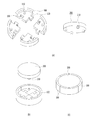
2 is a diagram illustrating a card board scratch according to an embodiment of the present invention;
Figure 3 is a diagram illustrating a variation of the invention illustrated in Figure 2,
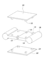
4 is a diagram illustrating an embodiment of the present invention in which a cover member is fastened to upper and lower ends,
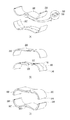
5 is a view illustrating another embodiment of the present invention in which the upper end portion and the lower end portion formed by the cover member and the separable support member are laminated.
DETAILED DESCRIPTION OF THE PREFERRED EMBODIMENT Hereinafter, the present invention will be described in detail with reference to preferred embodiments of the present invention and the accompanying drawings, wherein like reference numerals refer to like elements.
It is to be understood that when an element is referred to as being "comprising" another element in the description of the invention or in the claims, it is not to be construed as being limited to only that element, And the like.
First, a card board scratcher according to an embodiment of the present invention will be described with reference to FIG.
As illustrated in FIG. 2, the cardboard scratcher according to the present invention has at least two
At this time, the
The
2, the assembling
The assembled
The
In the example of FIG. 2, the assembling
As shown in FIG. 2, the separable supporting
Meanwhile, the
The
2, the
It can be confirmed that the
At this time, the shape of the upper and lower fastening
The upper and
The
In the example of FIG. 2, the
The position of the
Meanwhile, in the embodiment illustrated in FIG. 2, each
The outer wall has a circular shape and forms a space in which the
The
FIG. 3 shows a modification of the card board scratcher described above.
3, an outer wall is formed along a part of an edge of the
In the modification of FIG. 3, the outer walls are formed along the opposite side edges and the rear edges of the pair of
The shape of the
In the above example, the upper and
4 illustrates an embodiment in which the
In the embodiment shown in FIG. 4, the
When two or more
The pair of
The card board scratcher according to the embodiment shown in FIG. 4 has an advantage that both the upper surface and the lower surface can be used. By turning it upside down, the life of the product can be greatly increased.
Meanwhile, FIG. 5 illustrates a card board scratch according to another embodiment of the present invention.
The embodiment of the present invention illustrated in FIG. 5 is formed by stacking an upper end portion and a lower end portion, each of which is composed of a cover member and a separable support member.
5 (a) and 5 (b) show a lower end portion and an upper end portion, respectively.
As shown in FIG. 5 (a), the lower end portion has a structure in which the cover member 200 'is seated to the upper end of the assembly surface of the pair of separable support members 100'.
At this time, the
Preferably, a groove is formed on one side of the separable support member 100 'or the cover member 200', and a separate
As shown in FIG. 5 (b), the upper end portion also has a structure in which the
As shown in FIG. 5 (c), the assembly of the card board scratcher is completed by stacking the upper end portion above the assembled lower end portion.
At both ends of the upper end portion, a
The
The upper end portion can be stacked on the lower end portion by fastening the
In the embodiment shown in Fig. 5, as the assembly is completed, the upper end and the lower end are opened.
The shape of the cardboard scratcher according to the related art illustrated in FIG. 1 is similar to that of the conventional cardboard scratcher. However, not only can the life of the product be extended by replacing only the
The technical idea of the present invention has been described through several embodiments.
It will be apparent to those skilled in the art that various changes and modifications may be made to the embodiments described above from the description of the present invention. Further, although not explicitly shown or described, those skilled in the art can make various modifications including the technical idea of the present invention from the description of the present invention Which is still within the scope of the present invention. The above-described embodiments described with reference to the accompanying drawings are for the purpose of illustrating the present invention, and the scope of the present invention is not limited to these embodiments.
The present invention can be applied to the field of pet supplies technology.
100, 100 ': Separable support member
110: fastening counterpart
120:
130: Assembly groove
140:
200, 200 ': a cover member
210: upper and lower fastening portions
220: laminated support counterpart
300: Internal stiffener
Claims (5)
And a cover member coupled to an upper portion or a lower portion of the detachable support member,
Wherein the detachable support member and the cover member are cardboard materials,
Wherein the detachable support member includes an assembly groove and an assembling protrusion,
The assembling protrusion of one of the detachable support members is inserted into the assembling recess of the detachable support member adjacent to the detachable support member,
Wherein the cover member is a single non-detachable member, and the lower and upper locking portions are coupled to the corresponding fastening portions of the two or more separate supporting members so as to cover at least a part of the coupling portions of the two or more separate supporting members Card board scratcher.
The upper and lower fastening portions are protruded or recessed from the upper end surface or the lower end surface of the cover member,
Wherein the fastening corresponding portion is formed by being depressed or protruded from the upper surface or the lower surface of the separable support member,
Wherein the upper and lower fastening portions and the fastening corresponding portions have mutually corresponding shapes,
At least a part of the upper and lower fastening portions of any one of the cover members corresponds to a fastening corresponding portion of at least two adjacent separable support members and the remaining portion corresponds to the remaining fastening corresponding portions of the adjacent two or more detachable support members Wherein the card board scratcher is a cardboard scratcher.
Wherein the assembling protrusion protrudes from the one side of the separable support member by a predetermined length and has a shape in which the sectional area increases toward the distal end and then decreases,
Wherein an assembling recess corresponding to the assembling protruding portion is recessed by a predetermined length from one side of the adjacent separable supporting member, the depressed portion coinciding with the shape of the assembling protruding portion,
And two adjacent separable support members are assembled by pressingly inserting the assembling protrusion into the corresponding assembling recess.
Two or more separable support members are arranged in a planar adjacently to each other and each assembling protruding portion and a corresponding assembling recess are engaged,
Wherein the at least two separable support members are each formed with an outer wall protruding upward in a part of an edge,
And the cover member is seated and fastened to the inside of the space surrounded by the outer wall.
Two or more separable support members are arranged in a planar adjacently to each other and each assembling protruding portion and a corresponding assembling recess are engaged,
A side wall defining a seating position of the cover member is formed on the upper and lower end faces of each of the two or more removable support members,
Wherein the cover member is fastened to the upper and lower ends of the assembled surface of the assembled two or more removable pillar members, respectively, to a seating position defined by the side wall.
Priority Applications (1)
| Application Number | Priority Date | Filing Date | Title |
|---|---|---|---|
| KR1020150157623A KR20170054901A (en) | 2015-11-10 | 2015-11-10 | Card board cat scratcher |
Applications Claiming Priority (1)
| Application Number | Priority Date | Filing Date | Title |
|---|---|---|---|
| KR1020150157623A KR20170054901A (en) | 2015-11-10 | 2015-11-10 | Card board cat scratcher |
Publications (1)
| Publication Number | Publication Date |
|---|---|
| KR20170054901A true KR20170054901A (en) | 2017-05-18 |
Family
ID=59049055
Family Applications (1)
| Application Number | Title | Priority Date | Filing Date |
|---|---|---|---|
| KR1020150157623A KR20170054901A (en) | 2015-11-10 | 2015-11-10 | Card board cat scratcher |
Country Status (1)
| Country | Link |
|---|---|
| KR (1) | KR20170054901A (en) |
Cited By (2)
| Publication number | Priority date | Publication date | Assignee | Title |
|---|---|---|---|---|
| KR20190006159A (en) | 2017-07-09 | 2019-01-17 | 이해명 | Scratching board for cat |
| KR20210001894U (en) * | 2020-02-13 | 2021-08-23 | (주)잇펫 | Cat Scratcher |
-
2015
- 2015-11-10 KR KR1020150157623A patent/KR20170054901A/en active IP Right Grant
Cited By (2)
| Publication number | Priority date | Publication date | Assignee | Title |
|---|---|---|---|---|
| KR20190006159A (en) | 2017-07-09 | 2019-01-17 | 이해명 | Scratching board for cat |
| KR20210001894U (en) * | 2020-02-13 | 2021-08-23 | (주)잇펫 | Cat Scratcher |
Similar Documents
| Publication | Publication Date | Title |
|---|---|---|
| EP3037358B1 (en) | Packaging box | |
| USD942154S1 (en) | Cartridge brush | |
| WO2014091842A1 (en) | Container | |
| KR20170054901A (en) | Card board cat scratcher | |
| KR20100011793U (en) | Plane Jigsaw Puzzle | |
| USD845957S1 (en) | Cover member for electronic component | |
| USD941024S1 (en) | Transport storage box and lid in combination | |
| USD907996S1 (en) | Box for feeding animals | |
| USD912541S1 (en) | Watch case | |
| USD949708S1 (en) | Separable package | |
| KR101926420B1 (en) | Folding type box | |
| USD939265S1 (en) | Pizza pan | |
| USD862249S1 (en) | Container insert | |
| USD880352S1 (en) | Snap button | |
| JP6154499B1 (en) | container | |
| USD885169S1 (en) | Interchangeable securing device | |
| KR200486389Y1 (en) | cylinderical container assembly | |
| JP5086114B2 (en) | Tray with split function | |
| KR200392829Y1 (en) | Sectional container | |
| USD948812S1 (en) | Pet nail clipper | |
| USD942947S1 (en) | Coil component | |
| USD942393S1 (en) | Coil component | |
| KR101765748B1 (en) | Packaging container | |
| JP3173904U (en) | sink | |
| US426810A (en) | Moritz heinemann |
Legal Events
| Date | Code | Title | Description |
|---|---|---|---|
| A201 | Request for examination | ||
| E902 | Notification of reason for refusal | ||
| E701 | Decision to grant or registration of patent right |