KR20170052815A - Active stylus pen and driving method of the same, and touch sensing system having the active stylus pen - Google Patents
Active stylus pen and driving method of the same, and touch sensing system having the active stylus pen Download PDFInfo
- Publication number
- KR20170052815A KR20170052815A KR1020150154701A KR20150154701A KR20170052815A KR 20170052815 A KR20170052815 A KR 20170052815A KR 1020150154701 A KR1020150154701 A KR 1020150154701A KR 20150154701 A KR20150154701 A KR 20150154701A KR 20170052815 A KR20170052815 A KR 20170052815A
- Authority
- KR
- South Korea
- Prior art keywords
- signal
- tsp
- parameter
- drive signal
- parameter set
- Prior art date
Links
Images


Classifications
-
- G—PHYSICS
- G06—COMPUTING; CALCULATING OR COUNTING
- G06F—ELECTRIC DIGITAL DATA PROCESSING
- G06F3/00—Input arrangements for transferring data to be processed into a form capable of being handled by the computer; Output arrangements for transferring data from processing unit to output unit, e.g. interface arrangements
- G06F3/01—Input arrangements or combined input and output arrangements for interaction between user and computer
- G06F3/03—Arrangements for converting the position or the displacement of a member into a coded form
- G06F3/033—Pointing devices displaced or positioned by the user, e.g. mice, trackballs, pens or joysticks; Accessories therefor
- G06F3/0354—Pointing devices displaced or positioned by the user, e.g. mice, trackballs, pens or joysticks; Accessories therefor with detection of 2D relative movements between the device, or an operating part thereof, and a plane or surface, e.g. 2D mice, trackballs, pens or pucks
- G06F3/03545—Pens or stylus
-
- G—PHYSICS
- G06—COMPUTING; CALCULATING OR COUNTING
- G06F—ELECTRIC DIGITAL DATA PROCESSING
- G06F3/00—Input arrangements for transferring data to be processed into a form capable of being handled by the computer; Output arrangements for transferring data from processing unit to output unit, e.g. interface arrangements
- G06F3/01—Input arrangements or combined input and output arrangements for interaction between user and computer
- G06F3/03—Arrangements for converting the position or the displacement of a member into a coded form
- G06F3/041—Digitisers, e.g. for touch screens or touch pads, characterised by the transducing means
- G06F3/0416—Control or interface arrangements specially adapted for digitisers
Abstract
Description
The present invention relates to an active stylus pen, and more particularly, to an active stylus pen, a driving method thereof, and a touch sensing system including the active stylus pen.
A user interface (UI) enables a person (user) to easily control various electronic devices as he / she wants. Representative examples of such a user interface include a keypad, a keyboard, a mouse, an on screen display (OSD), a remote controller having infrared communication or radio frequency (RF) communication function, and the like. User interface technology has been developed to enhance the user's sensibility and ease of operation. Recently, the user interface has evolved into a touch UI, a voice recognition UI, a 3D UI, and the like.
The touch UI is essential for portable information devices. The touch UI is implemented by a method of forming a touch screen on the screen of a display device. Such a touch screen can be implemented in a capacitive manner. A touch screen having a capacitive touch sensor has a capacitance (capacitance) according to the input of a touch screen drive signal (hereinafter, referred to as 'TSP drive signal') when a finger or a conductive material touches ), That is, sensing the change of the charge of the touch sensor and sensing the touch input.
The capacitive touch sensor may be implemented as a self capacitance sensor or a mutual capacitance sensor. Each of the electrodes of the capacitance sensor may be connected in a one-to-one relationship with sensor wirings formed along one direction. The mutual capacitance sensor may be formed at the intersection of the sensor wirings orthogonal to each other with the dielectric layer interposed therebetween.
Recently, a stylus pen is used as a human interface device (HID) in smart phones and smart books. The stylus pen has the advantage of being able to input more finely than the finger. There are passive and active stylus pens. The passive stylus pen is difficult to detect the touch position because of the small change in capacitance at the point of contact with the touch screen. On the other hand, since the active stylus pen generates a pen driving signal by itself and outputs the pen driving signal to the contact point with the touch screen, the touch position detection is easier than the passive type, and development thereof is concentrated.
Conventionally, the active stylus pen generates a pen driving signal by simply delaying the TSP driving signal received from the touch screen, so that noise tends to be mixed into the pen driving signal. The pen drive signal is transmitted to the touch screen only during the touch sensor driving period and not transmitted to the touch screen during the display driving period, and the noise distorts the transmission timing of the pen drive signal. When the pen driving signal is transmitted to the touch screen during the display driving period, the image quality is degraded in the display panel including the touch screen.
Noise mixed into the pen drive signal may vary depending on the shape and size of the touch screen. The active stylus pen may be equipped with a noise filter to distinguish effective TSP drive signals from noise, in which case a large number of filters are required to remove various types of noise, thus increasing the hardware size.
In addition, since the conventional active stylus pen is designed only for a single product touch screen, it is difficult to cope with a case in which a signal different from the predetermined TSP driving signal is received.
Accordingly, it is an object of the present invention to provide an active stylus pen, a driving method thereof, and a touch sensing system including an active stylus pen so as to minimize noise incorporated into a pen driving signal without a separate noise filter.
Another object of the present invention is to provide an active stylus pen, a driving method thereof, and a touch sensing system including an active stylus pen, which are applicable not only to a single product but also to a touch screen of various products.
In order to achieve the above object, an active stylus pen of the present invention is an active stylus pen that operates in an Rx mode and a Tx mode based on a touch synchronous signal. The active stylus pen compares a TSP driving signal received from a touch screen with a preset reference voltage, And a validity checking unit for analyzing the comparator output pulse with reference to an Rx signal validity condition of a first parameter set among a plurality of parameter sets predefined in the Rx mode to check the validity of the TSP driving signal An STx generator for generating a pen drive signal synchronized with the TSP drive signal with reference to a Tx signal generation condition of the first parameter set in the Tx mode when the TSP drive signal is valid; Receives the TSP driving signal from the touch screen via a tip, and the Tx De comprises a switching unit for transmitting the pen driving signal to the touch screen through the conductive tip.
The validity checking unit determines that the TSP driving signal is valid when a plurality of consecutive comparator output pulses satisfy an effective period and effective duty corresponding to the Rx signal validity condition.
If the TSP drive signal is not valid, the conductive tip senses the pressure at which the touch screen is depressed.
The active stylus pen of the present invention calculates a period and a duty of the comparator output pulse in a preset phase unit when the pressure is sensed and then outputs a period and a duty when the calculated value is included within a predetermined margin range to the comparator output And an Rx parameter estimating unit that compares the signal estimation condition of each of the parameter sets except for the first parameter set among the parameter sets with the Rx parameter to determine a signal estimation condition most similar to the Rx parameter, Further comprising a parameter selection unit for selecting a parameter set having the first parameter set as a second parameter set and replacing the first parameter set with the selected second parameter set.
If the TSP drive signal is not valid, the STx generator generates a pen drive signal synchronized with the TSP drive signal with reference to the Tx signal generation condition of the second parameter set in the Tx mode.
According to another aspect of the present invention, there is provided a method of driving an active stylus pen operating in an Rx mode and a Tx mode based on a touch synchronous signal, the method comprising: comparing a TSP driving signal received from a touch screen with a predetermined reference voltage to generate a comparator output pulse Analyzing the comparator output pulse with reference to an Rx signal validation condition of a first parameter set among a plurality of predetermined parameter sets in the Rx mode to check the validity of the TSP driving signal; Generating a pen driving signal synchronized with the TSP driving signal with reference to a Tx signal generating condition of the first parameter set in the Tx mode when the signal is valid; Receiving a TSP drive signal and, in the Tx mode, via the conductive tip to the touch screen And transmitting the pen drive signal.
According to another aspect of the present invention, there is provided a touch sensing system including a touch screen, a touch driving device for applying a TSP driving signal to the touch screen based on a touch synchronizing signal and sensing a change in capacitance of the touch screen, The active stylus pen includes a receiving unit for generating a comparator output pulse by comparing a TSP driving signal received from a touch screen with a preset reference voltage, A validity checker for analyzing the comparator output pulse with reference to an Rx signal validation condition of a first parameter set among a plurality of parameter sets preset in the Rx mode to check the validity of the TSP drive signal, The Tx signal generation condition of the first parameter set in the Tx mode is set to An STx generator for generating a pen drive signal synchronized with the TSP drive signal in the Rx mode, and a controller for receiving the TSP drive signal from the touch screen via the conductive tip in the Rx mode, And a switching unit for transmitting the pen driving signal to the screen.
The present invention relates to an active stylus pen that operates in Rx mode and Tx mode based on a touch synchronous signal and discriminates the validity of a TSP driving signal input from a touch screen based on setting information of a default parameter set each time the Rx mode is switched , The pen driving signal synchronized with the TSP driving signal is generated only when the TSP driving signal is valid, thereby minimizing the noise incorporated into the pen driving signal without a separate noise filter.
Further, the present invention further analyzes the TSP drive signal when the TSP drive signal is sensed when the TSP drive signal is not sensed, selects a parameter set having the setup information most similar to the analysis result, After replacing the parameter set, the register information for generating the pen drive signal can be changed in real time according to the setting information of the selected parameter set. Accordingly, the present invention can dramatically improve the product compatibility, for example, the active stylus pen can be applied to a touch screen of various products.
BRIEF DESCRIPTION OF THE DRAWINGS Figure 1 is a schematic illustration of a touch sensing system of the present invention.
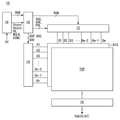
2 is a view illustrating a display device to which a touch sensing system according to an embodiment of the present invention is applied.
3 is a view showing an example of a touch screen implemented by a mutual capacitance sensor.
4 is a view showing an example of a touch screen implemented with a magnetic capacity sensor.
5 to 7 are views showing a touch driving device according to an embodiment of the present invention.
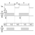
8 is a view showing a touch sensor driving period and a display driving period which are time-divided according to a touch synchronous signal.
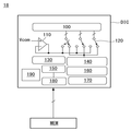
9 is a view showing an internal configuration of an active stylus pen according to the present invention.
10 is a view showing an operation procedure of an active stylus pen according to the present invention.
11 is a view showing an example of a plurality of predetermined parameter sets;
FIGS. 12 and 13 show examples in which a TSP driving signal input to the active stylus is distorted in various noise environments. FIG.
Fig. 14 is a diagram showing a comparator output pulse divided in units of a preset phase; Fig.
DETAILED DESCRIPTION OF THE PREFERRED EMBODIMENTS Reference will now be made in detail to the preferred embodiments of the present invention, examples of which are illustrated in the accompanying drawings. Like reference numerals throughout the specification denote substantially identical components. In the following description, a detailed description of known functions and configurations incorporated herein will be omitted when it may make the subject matter of the present invention rather unclear.
[Touch Sensing system]
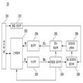
1 schematically shows a touch sensing system of the present invention.
Referring to FIG. 1, the touch sensing system of the present invention includes a
The
The
The
The construction and operation of the
[Display device]
FIG. 2 shows a display device to which a touch sensing system according to an embodiment of the present invention is applied. FIG. 3 shows an example of a touch screen implemented as a mutual capacitance sensor. 4 shows an example of a touch screen implemented by a magnetic capacity sensor. 5 to 7 show a touch driving apparatus according to an embodiment of the present invention.
2 to 7, the
The
The touch module includes a touch screen (TSP) and a
The touch screen (TSP) can be implemented in a capacitive manner that senses touch input through a plurality of capacitive sensors. The touch screen TSP includes a plurality of touch sensors having a capacitance. Capacitance can be divided into Self Capacitance and Mutual Capacitance. The electrostatic capacitance can be formed along a single-layer conductor wiring formed in one direction, and mutual capacitance can be formed between two orthogonal conductor wiring.
The touch screen TSP implemented by the mutual capacitive sensor Cm includes Tx electrode lines, Rx electrode lines intersecting the Tx electrode lines, and a plurality of Rx electrode lines at the intersections of the Tx electrode lines and the Rx electrode lines, And the touch sensors Cm formed thereon. The Tx electrode lines are driving signal lines for applying a TSP driving signal to each of the touch sensors Cm to supply electric charges to the touch sensors. The Rx electrode lines are sensor wirings connected to the touch sensors Cm to supply the charges of the touch sensors to the
The touch screen TSP implemented by the capacitance sensor Cs may be connected in a one-to-one relationship with the
The touch screen TSP may be bonded onto the upper polarizer plate of the display panel DIS or between the upper polarizer plate of the display panel DIS and the upper substrate. In addition, the touch sensors Cm or Cs of the touch screen TSP may be embedded in the pixel array of the display panel DIS. In order to embed the touch sensors Cm or Cs into the pixel array, the common electrode of the pixels may be divided into a plurality of segments. In this case, the touch sensors Cm or Cs may be implemented as divided common electrodes. One common electrode segment may be connected in common to a plurality of pixels and form one touch sensor. A common voltage is applied to the common electrode of the pixels during the display driving period, and a TSP driving signal is applied during the touch sensor driving period.
The
The touch-driving
Referring to FIG. 5, the
The driver IC DIC includes a touch
The touch
The
The timing
The timing
The timing control
The touch IC (TIC) is connected to a driving power source (not shown) to receive driving power. The touch IC TIC generates a TSP driving signal in response to the second level of the touch synchronizing signal Tsync and applies it to the touch sensors of the touch screen TSP. The TSP driving signal may be generated in various forms such as a square wave type pulse, a sinusoidal wave, and a triangular wave, but it is preferably implemented as a square wave. The TSP driving signal may be applied N times to each of the touch sensors so that the electric charge can be accumulated in the integrator of the touch IC (TIC) more than N (N is a natural number of 2 or more) times.
The noise may be increased in the touch sensor signal according to the change of the input image data. The DTX compensator 150 analyzes the input image data, removes noise components from the touch raw data according to the gradation change of the input image, and transmits the same to the touch IC (TIC). DTX stands for Display and Touch crosstalk. The contents of the
The touch IC TIC drives the
The touch IC (TIC) detects the amount of charge change before and after the touch input from the touch sensor signal, compares the amount of charge change with a predetermined threshold value, and determines the position of the touch sensor having the charge variation amount equal to or larger than the threshold value as the touch input area. The touch IC (TIC) calculates coordinates for each touch input and transmits touch data (TDATA (XY)) including touch input coordinate information to the external host system. The touch IC (TIC) includes an amplifier for amplifying the charge of the touch sensor, an integrator for accumulating the charge received from the touch sensor, an ADC (Analog to Digital Converter) for converting the voltage of the integrator into digital data, and an arithmetic logic section. The arithmetic logic unit compares the touch raw data output from the ADC with a threshold value, and executes a touch recognition algorithm that determines a touch input and calculates coordinates based on the comparison result.
The driver IC (DIC) and the touch IC (TIC) can transmit and receive signals through the SPI (Serial Peripheral Interface) interface.
Referring to FIG. 6, the
The driver IC DIC includes a touch
The
Driver IC (DIC) and MCU can send and receive signals through SPI (Serial Peripheral Interface) interface. The MCU compares the data (TDATA) with a threshold value with a touch, executes a touch recognition algorithm to determine the touch input according to the result of the comparison and to calculate coordinates.
Referring to FIG. 7, the
The driver IC DIC includes a touch
The memory MEM stores a register setting value related to the timing information necessary for the operation of the display driving circuit and the
The display module may include a display panel (DIS), a display driving circuit (12, 14, 16), and a host system (19).
The display panel DIS includes a liquid crystal layer formed between two substrates. The pixel array of the display panel DIS includes pixels formed in the pixel region defined by the data lines (D1 to Dm, m is a positive integer) and the gate lines (G1 to Gn, n is a positive integer) . Each of the pixels includes a TFT (Thin Film Transistor) formed at intersections of the data lines D1 to Dm and the gate lines G1 to Gn, a pixel electrode for charging a data voltage, A storage capacitor (Cst) for maintaining a voltage, and the like.
A black matrix, a color filter, and the like may be formed on the upper substrate of the display panel DIS. The lower substrate of the display panel DIS may be implemented with a COT (Color Filter On TFT) structure. In this case, the black matrix and the color filter can be formed on the lower substrate of the display panel DIS. The common electrode to which the common voltage is supplied may be formed on the upper substrate or the lower substrate of the display panel DIS. On the upper substrate and the lower substrate of the display panel DIS, a polarizing plate is attached, and an alignment film for forming a pre-tilt angle of the liquid crystal on the inner surface in contact with the liquid crystal is formed. A column spacer for maintaining a cell gap of the liquid crystal cell is formed between the upper substrate and the lower substrate of the display panel DIS.
A backlight unit may be disposed below the rear surface of the display panel DIS. The backlight unit is implemented as an edge type or direct type backlight unit, and irradiates the display panel (DIS) with light. The display panel DIS may be implemented in any known liquid crystal mode such as TN (Twisted Nematic) mode, VA (Vertical Alignment) mode, IPS (In Plane Switching) mode and FFS (Fringe Field Switching) mode.
The display driving circuit includes a
The
The
On the other hand, the touch synchronous signal TEN of FIG. 8 may be generated in the
During the touch sensor drive period TP, the
[ Stylus pen]
8 shows a touch sensor driving period and a display driving period which are time-divided according to a touch synchronous signal. 9 shows an internal configuration of an active stylus pen according to the present invention.
8 and 9, the
The
The
The receiving
After receiving the comparator output pulse SRx from the receiving
When the
The
The
When the
The
10 shows the operation procedure of the active stylus pen according to the present invention. 11 shows an example of a plurality of predetermined parameter sets. Figs. 12 and 13 show examples in which the TSP driving signal inputted to the active stylus pen is distorted in various noise environments. 14 shows that the comparator output pulses are divided by a predetermined phase unit.
The operation procedure of the active stylus pen according to the present invention will be described with reference to FIGS. 10 to 14. FIG.
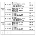
The active stylus pen according to the present invention (hereinafter, referred to as the present invention) has a plurality of predetermined parameter sets as shown in FIG. The parameter sets are pre-stored in the memory corresponding individually to the models of the touch screen (TSP). For example, in FIG. 11, parameter set 1 may correspond to a 5.5 inch touch screen, and parameter set 2 may correspond to a 15.6 inch touch screen.
The parameter sets include characteristic parameters of the Tx or Rx signal. The characteristic parameters include an SRx validation condition, a signal estimation condition, and an STx generation condition.
The SRx validity condition (Rx signal validity condition) is for checking the validity of the TSP drive signal (TS), and includes Rx pulse number and Rx pulse validation parameter. Rx pulse validation parameters include Rx pulse low / high width and Rx pulse low / high skip width. Here, the Rx pulse low / high width represents the effective period and effective duty of the Rx pulse.
The signal estimation condition is for changing the parameter set when the validity of the TSP driving signal (TS) is not satisfied. The signal estimation condition includes a low / high level for the high width of the measurement pulse and a low / high level for the low width of the measurement pulse .
The STx generation condition (Tx signal generation condition) is for generating a pen drive signal STx synchronized with the TSP drive signal TS and includes a Tx pulse number, a Tx pulse start time delay value, a Tx pulse low / And the like.
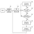
The present invention selects either one of the parameter sets as a default parameter set and then compares the TSP drive signal TS received from the touch screen TSP with a predetermined reference voltage to generate a comparator output pulse SRx, Mode, the comparator output pulse SRx is analyzed with reference to the SRx validity condition of the default parameter set to check the validity of the TSP driving signal TS (S1, S2). When the TSP drive signal TS is valid, the present invention generates a pen drive signal STx synchronized with the TSP drive signal TS with reference to the STx generation condition of the default parameter set in the Tx mode (S3 and S4) .
For example, the present invention selects parameter set 1 as a default parameter set and monitors whether the three consecutive pulse signals of the comparator output pulse SRx satisfy the SRx validity condition of parameter set 1, as in Fig. In this case, according to the present invention, when the row / high width of each of the three consecutive pulse signals satisfies the 100 占 margin value, it is determined that the TSP driving signal TS is valid, (STx).
On the other hand, when the TSP drive signal TS is not valid, the present invention performs the Rx pulse evaluation process and newly selects the most suitable parameter set among the parameter sets based on the result. The default parameter set is changed to a new parameter set by the Rx pulse evaluation process. This Rx pulse evaluation process starts at the time when the pressure is present.
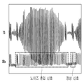
The Rx pulse evaluation process is performed to distinguish the noise from the normal signal at the comparator output signal SRx and to estimate the period and duty of the comparator output signal SRx through the high / low interval of the steady signal. The TSP drive signal (TS) input to the active stylus pen may be distorted in various noise environments. The noise is relatively large in the hovering state of the stylus pen as shown in Fig. 12, and relatively small in the contact state of the stylus pen as shown in Fig.
The Rx pulse evaluation process divides the input comparator output signal SRx into phase units (Phase 0 to 2) as shown in FIG. 14 and then outputs the signal amplitude (high range width or low range Width). Then, the Rx pulse evaluation process compares the calculated values in units of phases. The phases to be compared may be adjacent to each other or may be spaced in time. The Rx pulse evaluation process determines that there is no noise when the signal difference between the phases falls within the predetermined margin range, and selects the corresponding phase average value as the Rx parameter of the comparator output pulse SRx. Then, the Rx pulse evaluation process compares the selected Rx parameter with the signal estimation condition stored in each parameter set, and selects a parameter set having a signal estimation condition most similar to the Rx parameter as a new parameter set.
In other words, the present invention senses the pressure at which the conductive tip is depressed on the touch screen when the TSP drive signal (TS) is not valid, and uses the Rx pulse evaluation process, The cycle and duty of the comparator output pulse SRx are calculated by the preset phase unit (Phase 0 to 2), and the cycle and duty when the calculated value is included in the predetermined margin range are set as the Rx parameter of the comparator output pulse SRx I decide. The present invention compares the signal estimation condition of each of the remaining parameter sets except for the default parameter set among the parameter sets with the Rx parameter and selects a parameter set having the signal estimation condition most similar to the Rx parameter as a new parameter set , Thereby replacing the default parameter set with a new parameter set (S4, S5, S6, S7).
For example, under the determination that the TSP drive signal (TS) is not valid if the row / high width of each of the three consecutive pulse signals in Figure 11 does not satisfy the 100 占 margin value, the present invention performs the Rx pulse evaluation process do. If the Rx parameter calculated through the Rx pulse evaluation process belongs to the signal estimation condition of parameter set 2 as 190, 210, the present invention replaces the default parameter set with
As described above, according to the present invention, in the active stylus pen operating in the Rx mode and the Tx mode on the basis of the touch synchronous signal, each time the Rx mode is switched, the TSP driving signal And generates a pen drive signal synchronized with the TSP drive signal only when the TSP drive signal is effective, thereby minimizing the noise incorporated into the pen drive signal without a separate noise filter.
Further, the present invention further analyzes the TSP drive signal when the TSP drive signal is sensed when the TSP drive signal is not sensed, selects a parameter set having the setup information most similar to the analysis result, After replacing the parameter set, the register information for generating the pen drive signal can be changed in real time according to the setting information of the selected parameter set. Accordingly, the present invention can dramatically improve the product compatibility, for example, the active stylus pen can be applied to a touch screen of various products.
It will be apparent to those skilled in the art that various modifications and variations can be made in the present invention without departing from the spirit or scope of the invention. Therefore, the technical scope of the present invention should not be limited to the contents described in the detailed description of the specification, but should be defined by the claims.
10: display device 18: touch drive device
20: Stylus Pen 201: Conductive tip
202: switching unit 203:
204: validity checker 205: STx generator
206: Transmitting section 207:
208: Rx parameter evaluation unit 209: Parameter selection unit
Claims (12)
A receiver for comparing the TSP drive signal received from the touch screen with a predetermined reference voltage to generate a comparator output pulse;
A validity checker for analyzing the comparator output pulse with reference to an Rx signal validation condition of a first parameter set among a plurality of parameter sets preset in the Rx mode to check validity of the TSP drive signal;
An STx generating unit for generating a pen driving signal synchronized with the TSP driving signal with reference to a Tx signal generating condition of the first parameter set in the Tx mode when the TSP driving signal is valid; And
And a switching unit for receiving the TSP drive signal from the touch screen through the conductive tip in the Rx mode and transmitting the pen drive signal to the touch screen via the conductive tip in the Tx mode.
Wherein the validity checking unit determines that the TSP driving signal is valid when a plurality of consecutive comparator output pulses satisfy an effective period and an effective duty corresponding to the Rx signal validity condition.
A pressure-sensing unit configured to sense a pressure at which the conductive tip is pressed on the touch screen when the TSP drive signal is not valid;
The duty cycle of the comparator output pulse is calculated in units of a preset phase and the duty cycle of the output pulse is set to Rx parameter of the comparator output pulse when the pressure is detected within a predetermined margin range, A parameter evaluation unit; And
Compares the signal estimation condition of each of the parameter sets except for the first parameter set among the parameter sets with the Rx parameter, selects a parameter set having a signal estimation condition most similar to the Rx parameter as a second parameter set And a parameter selection unit that replaces the first parameter set with the selected second parameter set.
Wherein the STx generator generates a pen driving signal synchronized with the TSP driving signal with reference to a Tx signal generating condition of the second parameter set in the Tx mode when the TSP driving signal is invalid.
Comparing the TSP drive signal received from the touch screen with a predetermined reference voltage to generate a comparator output pulse;
Analyzing the comparator output pulse with reference to an Rx signal validation condition of a first parameter set among a plurality of predetermined parameter sets in the Rx mode to check validity of the TSP driving signal;
Generating a pen drive signal synchronized with the TSP drive signal with reference to a Tx signal generation condition of the first parameter set in the Tx mode when the TSP drive signal is valid; And
Receiving the TSP drive signal from the touch screen via a conductive tip in the Rx mode and transmitting the pen drive signal to the touch screen via the conductive tip in the Tx mode.
Wherein the validity checking step determines that the TSP driving signal is valid when a plurality of successive comparator output pulses satisfy an effective period and an effective duty corresponding to the Rx signal validity condition.
Sensing a pressure at which the conductive tip is depressed on the touch screen if the TSP drive signal is not valid;
Calculating a period and a duty of the comparator output pulse in a predetermined phase unit when the pressure is sensed and then setting a period and a duty when the calculated value is within a predetermined margin range to an Rx parameter of the comparator output pulse ; And
Comparing a signal estimation condition of each of the parameter sets other than the first parameter set among the parameter sets with the Rx parameter and selecting a parameter set having a signal estimation condition most similar to the RX parameter as a second parameter set And replacing the first set of parameters with the selected second set of parameters.
Generating a pen drive signal synchronized with the TSP drive signal when the TSP drive signal is not valid, the step of generating a pen drive signal synchronized with the TSP drive signal is performed by referring to a Tx signal generation condition of the second parameter set in the Tx mode, A driving method of an active stylus pen for generating a driving signal.
A touch driver that applies a TSP driving signal to the touch screen based on a touch synchronous signal and senses a capacitance change of the touch screen; And
And an active stylus pen operating in an Rx mode and a Tx mode based on the touch synchronous signal Tsync,
The active stylus pen includes:
A receiver for comparing the TSP drive signal received from the touch screen with a predetermined reference voltage to generate a comparator output pulse;
A validity checker for analyzing the comparator output pulse with reference to an Rx signal validation condition of a first parameter set among a plurality of parameter sets preset in the Rx mode to check validity of the TSP drive signal;
An STx generating unit for generating a pen driving signal synchronized with the TSP driving signal with reference to a Tx signal generating condition of the first parameter set in the Tx mode when the TSP driving signal is valid; And
A switch for receiving the TSP drive signal from the touch screen via the conductive tip in the Rx mode and transmitting the pen drive signal to the touch screen via the conductive tip in the Tx mode.
Wherein the validity checking unit determines that the TSP driving signal is valid when a plurality of consecutive comparator output pulses satisfy an effective period and an effective duty corresponding to the Rx signal validity condition.
A pressure-sensing unit configured to sense a pressure at which the conductive tip is pressed on the touch screen when the TSP drive signal is not valid;
The duty cycle of the comparator output pulse is calculated in units of a preset phase and the duty cycle of the output pulse is set to Rx parameter of the comparator output pulse when the pressure is detected within a predetermined margin range, A parameter evaluation unit; And
Compares the signal estimation condition of each of the parameter sets except for the first parameter set among the parameter sets with the Rx parameter, selects a parameter set having a signal estimation condition most similar to the Rx parameter as a second parameter set And a parameter selection unit for replacing the first parameter set with the selected second parameter set.
When the TSP drive signal is invalid, the STx generator generates a pen drive signal synchronized with the TSP drive signal with reference to a Tx signal generation condition of the second parameter set in the Tx mode.
Priority Applications (1)
| Application Number | Priority Date | Filing Date | Title |
|---|---|---|---|
| KR1020150154701A KR20170052815A (en) | 2015-11-04 | 2015-11-04 | Active stylus pen and driving method of the same, and touch sensing system having the active stylus pen |
Applications Claiming Priority (1)
| Application Number | Priority Date | Filing Date | Title |
|---|---|---|---|
| KR1020150154701A KR20170052815A (en) | 2015-11-04 | 2015-11-04 | Active stylus pen and driving method of the same, and touch sensing system having the active stylus pen |
Publications (1)
| Publication Number | Publication Date |
|---|---|
| KR20170052815A true KR20170052815A (en) | 2017-05-15 |
Family
ID=58739549
Family Applications (1)
| Application Number | Title | Priority Date | Filing Date |
|---|---|---|---|
| KR1020150154701A KR20170052815A (en) | 2015-11-04 | 2015-11-04 | Active stylus pen and driving method of the same, and touch sensing system having the active stylus pen |
Country Status (1)
| Country | Link |
|---|---|
| KR (1) | KR20170052815A (en) |
Cited By (1)
| Publication number | Priority date | Publication date | Assignee | Title |
|---|---|---|---|---|
| US11747922B2 (en) | 2020-10-22 | 2023-09-05 | Samsung Display Co., Ltd. | Input device driving method and interface device using the same |
-
2015
- 2015-11-04 KR KR1020150154701A patent/KR20170052815A/en unknown
Cited By (1)
| Publication number | Priority date | Publication date | Assignee | Title |
|---|---|---|---|---|
| US11747922B2 (en) | 2020-10-22 | 2023-09-05 | Samsung Display Co., Ltd. | Input device driving method and interface device using the same |
Similar Documents
| Publication | Publication Date | Title |
|---|---|---|
| CN108255333B (en) | Touch sensing system and driving method thereof | |
| US10324547B2 (en) | Active stylus pen, touch sensing system and driving method thereof | |
| US10268285B2 (en) | Stylus pen, touch sensing system and driving method thereof | |
| KR102340937B1 (en) | Stylus pen and touch sensing system and driving method of the same | |
| US9665221B2 (en) | Touch sensing system | |
| US9946403B2 (en) | Display device, method for driving the same, and driving circuit thereof | |
| US9465497B2 (en) | Touch sensing system | |
| US10324567B2 (en) | Touch sensing system and method of reducing latency thereof | |
| CN106997255B (en) | Touch sensing system with active stylus and touch driving device | |
| KR102520695B1 (en) | Active stylus pen and touch sensing system and driving method of the same | |
| US20170192591A1 (en) | Touch sensing system including active stylus pen | |
| KR102088906B1 (en) | Appratus and method for driving touch screen | |
| KR101679986B1 (en) | Touch sensor driving device and method and display divice including the same | |
| KR102364099B1 (en) | Active stylus pen and touch sensing system and driving method of the same | |
| KR20130028360A (en) | Apparatus and method for driving touch screen | |
| KR20170036940A (en) | Active touch pen and touch sensing system and driving method of the same | |
| KR20140065602A (en) | Touch sensing system and driving method thereof | |
| KR101667078B1 (en) | Touch sensing device, system and enhancement method of touch report rate thereof | |
| KR20150139013A (en) | Sensing system | |
| KR20170052815A (en) | Active stylus pen and driving method of the same, and touch sensing system having the active stylus pen | |
| KR101942849B1 (en) | Electronic device having a touch sensor and driving method thereof | |
| KR20170015648A (en) | Stylus pen and touch sensing system and driving method of the same | |
| US9733778B2 (en) | Touch sensing apparatus | |
| KR101862398B1 (en) | Display having touch sensor | |
| KR20170015776A (en) | Stylus pen and touch sensing system and driving method of the same |