KR20170052629A - Acoustic device - Google Patents
Acoustic device Download PDFInfo
- Publication number
- KR20170052629A KR20170052629A KR1020177009228A KR20177009228A KR20170052629A KR 20170052629 A KR20170052629 A KR 20170052629A KR 1020177009228 A KR1020177009228 A KR 1020177009228A KR 20177009228 A KR20177009228 A KR 20177009228A KR 20170052629 A KR20170052629 A KR 20170052629A
- Authority
- KR
- South Korea
- Prior art keywords
- chamber
- tubular wall
- acoustic
- expansion chamber
- acoustic device
- Prior art date
Links
- 230000002093 peripheral effect Effects 0.000 claims abstract description 48
- 238000000034 method Methods 0.000 claims description 24
- 238000012546 transfer Methods 0.000 claims description 24
- 239000000463 material Substances 0.000 claims description 12
- 238000000638 solvent extraction Methods 0.000 claims description 6
- 239000010408 film Substances 0.000 description 32
- 230000005540 biological transmission Effects 0.000 description 6
- 238000005259 measurement Methods 0.000 description 5
- 239000011159 matrix material Substances 0.000 description 4
- 230000002829 reductive effect Effects 0.000 description 4
- 230000003584 silencer Effects 0.000 description 4
- 239000002023 wood Substances 0.000 description 4
- 229920000122 acrylonitrile butadiene styrene Polymers 0.000 description 3
- 230000008901 benefit Effects 0.000 description 3
- 238000002485 combustion reaction Methods 0.000 description 3
- 238000004891 communication Methods 0.000 description 3
- 230000000052 comparative effect Effects 0.000 description 3
- -1 polyethylene Polymers 0.000 description 3
- 238000012360 testing method Methods 0.000 description 3
- 239000004743 Polypropylene Substances 0.000 description 2
- 239000004676 acrylonitrile butadiene styrene Substances 0.000 description 2
- 230000009977 dual effect Effects 0.000 description 2
- 230000000694 effects Effects 0.000 description 2
- 238000001125 extrusion Methods 0.000 description 2
- 238000001746 injection moulding Methods 0.000 description 2
- 230000000670 limiting effect Effects 0.000 description 2
- 238000012986 modification Methods 0.000 description 2
- 230000004048 modification Effects 0.000 description 2
- 230000036961 partial effect Effects 0.000 description 2
- 229920001155 polypropylene Polymers 0.000 description 2
- 230000009467 reduction Effects 0.000 description 2
- 229920005989 resin Polymers 0.000 description 2
- 239000011347 resin Substances 0.000 description 2
- 239000007787 solid Substances 0.000 description 2
- 230000003595 spectral effect Effects 0.000 description 2
- 230000003068 static effect Effects 0.000 description 2
- 239000004677 Nylon Substances 0.000 description 1
- 239000004698 Polyethylene Substances 0.000 description 1
- 239000004793 Polystyrene Substances 0.000 description 1
- 238000010521 absorption reaction Methods 0.000 description 1
- 239000012814 acoustic material Substances 0.000 description 1
- XECAHXYUAAWDEL-UHFFFAOYSA-N acrylonitrile butadiene styrene Chemical compound C=CC=C.C=CC#N.C=CC1=CC=CC=C1 XECAHXYUAAWDEL-UHFFFAOYSA-N 0.000 description 1
- 238000004378 air conditioning Methods 0.000 description 1
- 230000004075 alteration Effects 0.000 description 1
- 230000033228 biological regulation Effects 0.000 description 1
- 238000009530 blood pressure measurement Methods 0.000 description 1
- 238000000071 blow moulding Methods 0.000 description 1
- 238000007664 blowing Methods 0.000 description 1
- 230000008859 change Effects 0.000 description 1
- 239000000567 combustion gas Substances 0.000 description 1
- 230000006835 compression Effects 0.000 description 1
- 238000007906 compression Methods 0.000 description 1
- 238000000748 compression moulding Methods 0.000 description 1
- 238000001816 cooling Methods 0.000 description 1
- 238000005520 cutting process Methods 0.000 description 1
- 238000013016 damping Methods 0.000 description 1
- 238000013461 design Methods 0.000 description 1
- 238000009826 distribution Methods 0.000 description 1
- 239000012530 fluid Substances 0.000 description 1
- 230000003993 interaction Effects 0.000 description 1
- 230000002452 interceptive effect Effects 0.000 description 1
- 238000005304 joining Methods 0.000 description 1
- 239000002184 metal Substances 0.000 description 1
- 238000000465 moulding Methods 0.000 description 1
- 229920001778 nylon Polymers 0.000 description 1
- 239000002245 particle Substances 0.000 description 1
- 229920000573 polyethylene Polymers 0.000 description 1
- 229920002223 polystyrene Polymers 0.000 description 1
- 230000000644 propagated effect Effects 0.000 description 1
- 230000001681 protective effect Effects 0.000 description 1
- 238000004080 punching Methods 0.000 description 1
- 230000001105 regulatory effect Effects 0.000 description 1
- 230000004044 response Effects 0.000 description 1
- 238000001175 rotational moulding Methods 0.000 description 1
- 239000000243 solution Substances 0.000 description 1
- 238000007655 standard test method Methods 0.000 description 1
- 238000010998 test method Methods 0.000 description 1
- 229920005992 thermoplastic resin Polymers 0.000 description 1
- 229920001187 thermosetting polymer Polymers 0.000 description 1
- 239000010409 thin film Substances 0.000 description 1
Images


Classifications
-
- F—MECHANICAL ENGINEERING; LIGHTING; HEATING; WEAPONS; BLASTING
- F01—MACHINES OR ENGINES IN GENERAL; ENGINE PLANTS IN GENERAL; STEAM ENGINES
- F01N—GAS-FLOW SILENCERS OR EXHAUST APPARATUS FOR MACHINES OR ENGINES IN GENERAL; GAS-FLOW SILENCERS OR EXHAUST APPARATUS FOR INTERNAL COMBUSTION ENGINES
- F01N1/00—Silencing apparatus characterised by method of silencing
- F01N1/003—Silencing apparatus characterised by method of silencing by using dead chambers communicating with gas flow passages
- F01N1/006—Silencing apparatus characterised by method of silencing by using dead chambers communicating with gas flow passages comprising at least one perforated tube extending from inlet to outlet of the silencer
-
- F—MECHANICAL ENGINEERING; LIGHTING; HEATING; WEAPONS; BLASTING
- F01—MACHINES OR ENGINES IN GENERAL; ENGINE PLANTS IN GENERAL; STEAM ENGINES
- F01N—GAS-FLOW SILENCERS OR EXHAUST APPARATUS FOR MACHINES OR ENGINES IN GENERAL; GAS-FLOW SILENCERS OR EXHAUST APPARATUS FOR INTERNAL COMBUSTION ENGINES
- F01N1/00—Silencing apparatus characterised by method of silencing
- F01N1/02—Silencing apparatus characterised by method of silencing by using resonance
- F01N1/026—Annular resonance chambers arranged concentrically to an exhaust passage and communicating with it, e.g. via at least one opening in the exhaust passage
-
- F—MECHANICAL ENGINEERING; LIGHTING; HEATING; WEAPONS; BLASTING
- F01—MACHINES OR ENGINES IN GENERAL; ENGINE PLANTS IN GENERAL; STEAM ENGINES
- F01N—GAS-FLOW SILENCERS OR EXHAUST APPARATUS FOR MACHINES OR ENGINES IN GENERAL; GAS-FLOW SILENCERS OR EXHAUST APPARATUS FOR INTERNAL COMBUSTION ENGINES
- F01N13/00—Exhaust or silencing apparatus characterised by constructional features ; Exhaust or silencing apparatus, or parts thereof, having pertinent characteristics not provided for in, or of interest apart from, groups F01N1/00 - F01N5/00, F01N9/00, F01N11/00
- F01N13/02—Exhaust or silencing apparatus characterised by constructional features ; Exhaust or silencing apparatus, or parts thereof, having pertinent characteristics not provided for in, or of interest apart from, groups F01N1/00 - F01N5/00, F01N9/00, F01N11/00 having two or more separate silencers in series
-
- F—MECHANICAL ENGINEERING; LIGHTING; HEATING; WEAPONS; BLASTING
- F02—COMBUSTION ENGINES; HOT-GAS OR COMBUSTION-PRODUCT ENGINE PLANTS
- F02M—SUPPLYING COMBUSTION ENGINES IN GENERAL WITH COMBUSTIBLE MIXTURES OR CONSTITUENTS THEREOF
- F02M35/00—Combustion-air cleaners, air intakes, intake silencers, or induction systems specially adapted for, or arranged on, internal-combustion engines
- F02M35/12—Intake silencers ; Sound modulation, transmission or amplification
- F02M35/1205—Flow throttling or guiding
- F02M35/1216—Flow throttling or guiding by using a plurality of holes, slits, protrusions, perforations, ribs or the like; Surface structures; Turbulence generators
-
- F—MECHANICAL ENGINEERING; LIGHTING; HEATING; WEAPONS; BLASTING
- F02—COMBUSTION ENGINES; HOT-GAS OR COMBUSTION-PRODUCT ENGINE PLANTS
- F02M—SUPPLYING COMBUSTION ENGINES IN GENERAL WITH COMBUSTIBLE MIXTURES OR CONSTITUENTS THEREOF
- F02M35/00—Combustion-air cleaners, air intakes, intake silencers, or induction systems specially adapted for, or arranged on, internal-combustion engines
- F02M35/12—Intake silencers ; Sound modulation, transmission or amplification
- F02M35/1255—Intake silencers ; Sound modulation, transmission or amplification using resonance
-
- F—MECHANICAL ENGINEERING; LIGHTING; HEATING; WEAPONS; BLASTING
- F24—HEATING; RANGES; VENTILATING
- F24F—AIR-CONDITIONING; AIR-HUMIDIFICATION; VENTILATION; USE OF AIR CURRENTS FOR SCREENING
- F24F13/00—Details common to, or for air-conditioning, air-humidification, ventilation or use of air currents for screening
- F24F13/24—Means for preventing or suppressing noise
-
- G—PHYSICS
- G10—MUSICAL INSTRUMENTS; ACOUSTICS
- G10K—SOUND-PRODUCING DEVICES; METHODS OR DEVICES FOR PROTECTING AGAINST, OR FOR DAMPING, NOISE OR OTHER ACOUSTIC WAVES IN GENERAL; ACOUSTICS NOT OTHERWISE PROVIDED FOR
- G10K11/00—Methods or devices for transmitting, conducting or directing sound in general; Methods or devices for protecting against, or for damping, noise or other acoustic waves in general
- G10K11/16—Methods or devices for protecting against, or for damping, noise or other acoustic waves in general
- G10K11/161—Methods or devices for protecting against, or for damping, noise or other acoustic waves in general in systems with fluid flow
-
- F—MECHANICAL ENGINEERING; LIGHTING; HEATING; WEAPONS; BLASTING
- F01—MACHINES OR ENGINES IN GENERAL; ENGINE PLANTS IN GENERAL; STEAM ENGINES
- F01N—GAS-FLOW SILENCERS OR EXHAUST APPARATUS FOR MACHINES OR ENGINES IN GENERAL; GAS-FLOW SILENCERS OR EXHAUST APPARATUS FOR INTERNAL COMBUSTION ENGINES
- F01N2470/00—Structure or shape of gas passages, pipes or tubes
- F01N2470/02—Tubes being perforated
-
- F—MECHANICAL ENGINEERING; LIGHTING; HEATING; WEAPONS; BLASTING
- F01—MACHINES OR ENGINES IN GENERAL; ENGINE PLANTS IN GENERAL; STEAM ENGINES
- F01N—GAS-FLOW SILENCERS OR EXHAUST APPARATUS FOR MACHINES OR ENGINES IN GENERAL; GAS-FLOW SILENCERS OR EXHAUST APPARATUS FOR INTERNAL COMBUSTION ENGINES
- F01N2470/00—Structure or shape of gas passages, pipes or tubes
- F01N2470/24—Concentric tubes or tubes being concentric to housing, e.g. telescopically assembled
-
- F—MECHANICAL ENGINEERING; LIGHTING; HEATING; WEAPONS; BLASTING
- F01—MACHINES OR ENGINES IN GENERAL; ENGINE PLANTS IN GENERAL; STEAM ENGINES
- F01N—GAS-FLOW SILENCERS OR EXHAUST APPARATUS FOR MACHINES OR ENGINES IN GENERAL; GAS-FLOW SILENCERS OR EXHAUST APPARATUS FOR INTERNAL COMBUSTION ENGINES
- F01N2490/00—Structure, disposition or shape of gas-chambers
- F01N2490/15—Plurality of resonance or dead chambers
- F01N2490/155—Plurality of resonance or dead chambers being disposed one after the other in flow direction
-
- F—MECHANICAL ENGINEERING; LIGHTING; HEATING; WEAPONS; BLASTING
- F24—HEATING; RANGES; VENTILATING
- F24F—AIR-CONDITIONING; AIR-HUMIDIFICATION; VENTILATION; USE OF AIR CURRENTS FOR SCREENING
- F24F13/00—Details common to, or for air-conditioning, air-humidification, ventilation or use of air currents for screening
- F24F13/24—Means for preventing or suppressing noise
- F24F2013/245—Means for preventing or suppressing noise using resonance
Abstract
제공된 음향 장치는 팽창 챔버를 한정하는 외부 하우징, 및 팽창 챔버를 통해 연장되고 팽창 챔버를 중앙 챔버와 중앙 챔버에 인접한 주변 챔버로 구획하는 벽을 포함하고, 입구 및 출구는 중앙 챔버와 연통하고, 벽은 중앙 챔버와 팽창 챔버로의 그리고 그들로부터의 공기 이동을 허용하도록 관통 형성되는 복수의 개구를 포함하며, 복수의 개구는 100 MKS 레일(Rayl) 내지 5000 MKS 레일 범위의 평균 유동 저항을 제공하도록 크기가 설정된다. 음향 장치는, 유리하게는, 팽창 챔버를 가로지른 압력 강하를 감소시키기 위해 공기 유동을 간소화하면서 상당한 음향 감쇠를 나타낸다.The acoustic apparatus provided includes an outer housing defining an expansion chamber, and a wall extending through the expansion chamber and defining an expansion chamber into a central chamber and a peripheral chamber adjacent the central chamber, the inlet and the outlet communicating with the central chamber, Wherein the plurality of openings are sized to provide an average flow resistance in the range of 100 MKS rails to 5000 MKS rails, Is set. The acoustic device advantageously exhibits significant acoustic attenuation while streamlining the air flow to reduce the pressure drop across the expansion chamber.
Description
소음 감소를 위한 장치들 및 방법들이 제공된다. 보다 상세하게는, 제공된 물품들 및 방법들은 유동 시스템과 연관된 소음을 감소시키는 것에 관한 것이다.Devices and methods for noise reduction are provided. More particularly, the provided articles and methods relate to reducing noise associated with a flow system.
연소 엔진들, 전기 팬 모터들, 팬들, 난방-환기-공조(heating-ventilation-air conditioning, HVAC) 시스템들, 흡기 시스템 등과 연관된 공기 중의 음향 에너지는 소음 공해에 기여하며 대체로 바람직하지 못하다. 소음은 사람이 차지하는 임의의 장소에서, 예컨대 가정, 작업 환경, 차량 및 심지어 호흡기와 같은 개인 보호 장비 내에서 문제가 될 수 있다. 공기 중 소음을 줄이는 것은 자동차 시장에서 특히 중요하다. 배기 소음에 대한 최소 소음 감소 표준은 승객 및 상업용 차량에 대한 수많은 정부 규제의 대상이다. 또한, 낮은 객실 소음은 오랫동안 승용차의 중요한 특징이었다.Acoustic energy in the air associated with combustion engines, electric fan motors, fans, heating-ventilation-air conditioning (HVAC) systems, intake systems, etc., contribute to noise pollution and are generally undesirable. Noise can be a problem in any place occupied by a person, for example in personal protective equipment such as homes, work environments, vehicles and even respirators. Reducing airborne noise is particularly important in the automotive market. The minimum noise reduction standard for exhaust noise is the subject of numerous government regulations on passenger and commercial vehicles. In addition, low room noise has long been an important feature of passenger cars.
음향 에너지를 그의 소스에서 제거 또는 감소하는 것이 바람직하지만, 항상 가능하지는 않다. 자동차에서, 예를 들어, 공기 중 음향 에너지는 내연 기관 챔버 배기 가스의 급속한 팽창으로부터 유래한다. 이러한 연소 가스가 배출됨에 따라, 음파면(sound wave front)은 배기 시스템을 통해 음속으로 이동한다. 자동차 소음은 또한 냉각 팬, 교류 발전기 및 기타 엔진 액세서리로부터 발생할 수 있다. 따라서, 제조사들은 이들 장치에 의해 방출되는 소음을 실질적으로 감소시킬 수 있는 음향 기술에 관심을 기울여왔다.It is desirable, but not always possible, to remove or reduce the acoustic energy from its source. In automobiles, for example, the acoustic energy in the air comes from the rapid expansion of the internal combustion engine chamber exhaust. As this combustion gas is evacuated, the sound wave front travels at a sonic speed through the exhaust system. Car noise can also occur from cooling fans, alternators and other engine accessories. Thus, manufacturers have been interested in acoustic techniques that can substantially reduce the noise emitted by these devices.
감소시킬 소음의 특성은 효율적인 배기 또는 HVAC 소음기를 개발하는 데 있어 상당히 중요하다. 연소 엔진 또는 HVAC 시스템으로부터의 공기 중 음향 에너지는 전형적으로 복수의 소스들이 원인이며, 소스들 각각은 그 자신의 특성 주파수를 통해 음을 방출한다. 통상적으로, 음파의 감쇠는 음향 에너지가 소산되거나 민감한 위치로부터 멀리 벗어나게 하는 표면들 또는 구조물들에 음파가 맞닥뜨리게 함으로써 달성될 수 있는데; 이러한 상호 작용은 높은 진폭의 개개의 음파 성분을 보다 낮은 진폭의 복수의 음파로 바꾸어, 그에 따라 전체 소음 레벨을 낮춘다. 이러한 장치는, 효율적이기 위해, 각각의 음파의 위상 관계를 변경하도록 개별적으로 조정되는 일련의 구성요소 장치를 포함할 수 있다.The characteristics of the noise to be reduced are crucial in developing an efficient exhaust or HVAC silencer. Acoustic energy in the air from a combustion engine or HVAC system is typically caused by a plurality of sources, each of which emits sound through its own characteristic frequency. Typically, the attenuation of a sound wave can be achieved by bringing the sound waves into contact with surfaces or structures that cause the acoustic energy to dissipate or deviate from a sensitive location; This interaction translates the individual sound wave components of high amplitude into a plurality of sound waves of lower amplitude, thereby lowering the overall noise level. Such an arrangement may include a series of component devices that are individually adjusted to change the phase relationship of each sound wave to be efficient.
문헌에 기술된 바와 같이, 음향 소음기의 음향 에너지를 감쇠시키기 위해 천공 필름이 사용될 수 있다. 그러나, 이들 개시물에 기재된 장치는 대체로 정적 유동에 사용되며, 아래에서 설명되는 바와 같이 장치와 연관된 압력 강하에 대한 그러한 천공 필름의 영향을 다루지는 않는다.As described in the literature, a perforated film can be used to attenuate the acoustic energy of the acoustic silencer. However, the devices described in these disclosures are generally used for static flow and do not address the effect of such perforated films on the pressure drop associated with the device as described below.
압력 강하는 음향 관리에 있어서 종종 이해되지 않는 문제이다. 본 명세서에서 사용된 바와 같이, 이것은 인라인 음향 장치의 입구 단부와 출구 단부 사이에서 측정된 공기압의 차이이다. 높은 압력 강하는 종종 소음기에서의 열악한 유동 특성을 초래하며, 이는 이어서 과도한 열 및 비효율적인 장치 성능으로 이어질 수 있다. 예를 들어, 고성능 차량들에서, 배기 시스템에서의 높은 압력 강하는 감소된 마력 및 토크로 이어질 수 있다. 마찬가지로, HVAC 시스템에서, 높은 압력 강하는 공기를 구동하는 팬이 더 힘들게 작동하도록 강제하여, 높은 전력 소비를 초래한다. 음향 감쇠를 개선하는 소음기의 태양들은 대체로 압력 강하를 증가시키는 경향이 있으며, 그 반대의 경우도 성립하여, 따라서 기술적 해결책은 종종 이들 2개의 고려 사항들 사이의 균형으로서 간주되어 왔다.Pressure drop is a problem that is often not understood in sound management. As used herein, this is the difference in air pressure measured between the inlet end and the outlet end of the inline acoustic apparatus. High pressure drop often results in poor flow characteristics in the silencer, which in turn can lead to excessive heat and inefficient device performance. For example, in high performance vehicles, the high pressure drop in the exhaust system can lead to reduced horsepower and torque. Similarly, in HVAC systems, high pressure drops force the fan that drives the air to work harder, resulting in higher power consumption. The silencer aspects of improving acoustic damping tend to increase pressure drop generally and vice versa, so technical solutions have often been regarded as a balance between these two considerations.
제공된 음향 장치는 하나 이상의 천공 필름을 팽창 챔버의 공기 유동장(air flow field)에 통합시킴으로써 음향 감쇠 및 압력 강하의 이중 문제를 해결하고 있다. 천공 필름을 사용하여 250 ㎐ 내지 4000 ㎐의 인간 음성 범위에 걸친 넓은 목표 주파수 범위에서 압력파들을 감쇠시킴으로써 이들 장치들이 상당한 음향 감쇠를 얻을 수 있게 하였다. 또한, 이들 장치들은 팽창 챔버를 통한 공기 유동을 용이하게 하여, 그에 의해 천공 필름을 포함하지 않는 종래의 장치들의 것과 비교하여 유동 성능을 개선시킨다.The acoustic apparatus provided solves the dual problem of acoustic attenuation and pressure drop by incorporating one or more apertured films into the air flow field of the expansion chamber. Perforated films were used to attenuate pressure waves over a wide range of target frequencies over the human voice range of 250 Hz to 4000 Hz to enable these devices to achieve significant acoustic attenuation. In addition, these devices facilitate air flow through the expansion chamber, thereby improving flow performance compared to conventional devices that do not include a perforated film.
일 태양에서, 음향 장치가 제공된다. 음향 장치는 입구 및 출구를 갖고: 팽창 챔버를 한정하는 외부 하우징; 및 팽창 챔버를 통해 연장되고 팽창 챔버를 중앙 챔버와 중앙 챔버에 인접한 주변 챔버로 구획하는 관형 벽을 포함하고, 여기서 입구 및 출구 양쪽 모두는 중앙 챔버와 연통하고, 관형 벽은 중앙 챔버와 주변 챔버 사이의 공기 유동을 허용하도록 관통 형성되는 복수의 개구를 포함하며, 복수의 개구는 100 MKS 레일(Rayl) 내지 5000 MKS 레일 범위의 평균 유동 저항을 제공하도록 구성된다.In one aspect, a sound device is provided. The acoustic device has an inlet and an outlet: an outer housing defining an expansion chamber; And a tubular wall extending through the expansion chamber and partitioning the expansion chamber into a central chamber and a peripheral chamber adjacent the central chamber wherein both the inlet and the outlet communicate with the central chamber and the tubular wall extends between the central chamber and the peripheral chamber Wherein the plurality of openings are configured to provide an average flow resistance in the range of 100 MKS rails to 5000 MKS rails.
다른 태양에서, 팽창 챔버를 한정하는 외부 하우징, 팽창 챔버를 통해 연장되고 팽창 챔버를 중앙 챔버와 중앙 챔버에 인접한 주변 챔버로 구획하는 관형 벽, 및 중앙 챔버의 대향 단부들과 연통하는 입구 및 출구를 갖는 음향 장치를 사용하여 공기 중의 음향 에너지를 감쇠시키는 방법이 제공되는데, 이 방법은 중앙 챔버를 통해 공기를 유동시키는 단계; 및 관형 벽에 배치된 복수의 개구 - 복수의 개구는 100 MKS 레일 내지 5000 MKS 레일 범위의 평균 유동 저항을 제공함 - 를 통해 중앙 챔버로부터 음향 에너지를 지향시키는 단계를 포함한다.In another aspect there is provided an inflation chamber comprising an outer housing defining an inflation chamber, a tubular wall extending through the inflation chamber and partitioning the inflation chamber into a central chamber and a peripheral chamber adjacent the central chamber, and an inlet and an outlet communicating with opposite ends of the central chamber There is provided a method of attenuating acoustic energy in the air using an acoustic device having a plurality of acoustic devices, the method comprising: flowing air through a central chamber; And directing acoustic energy from the central chamber through the plurality of openings disposed in the tubular wall, the plurality of openings providing an average flow resistance in the range of 100 MKS rails to 5000 MKS rails.
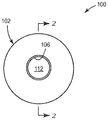
도 1은 일 예시적인 실시 형태에 따른 음향 장치의 정면도이다.
도 2는 도 1의 음향 장치의 측단면도이다.
도 3은 다른 예시적인 실시 형태에 따른 음향 장치의 정면도이다.
도 4는 도 3의 음향 장치의 측단면도이다.
도 5a 내지 도 5d는 음향 장치의 추가의 예시적인 구성들의 사시도들이다.
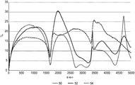
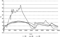
도 6은 단일 팽창 챔버를 갖는 다양한 음향 장치들에 대한 전송 손실(데시벨 단위) 대 주파수(헤르츠 단위)의 스펙트럼 플롯이다.
도 7은 이중 팽창 챔버를 갖는 다양한 음향 장치들에 대한 전송 손실(데시벨 단위) 대 주파수(헤르츠 단위)의 스펙트럼 플롯이다.
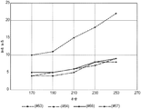
도 8은 단일 팽창 챔버를 갖는 다양한 음향 장치들에 대한 공기 압력 강하(파스칼) 대 유량(리터/분)을 비교하는 플롯이다.1 is a front view of an acoustic device according to one exemplary embodiment.
2 is a side sectional view of the acoustic device of Fig.
3 is a front view of an acoustic device according to another exemplary embodiment.
4 is a side cross-sectional view of the acoustic device of Fig.
Figures 5A-D are perspective views of further exemplary configurations of the acoustic device.
6 is a spectral plot of transmission loss (in decibels units) versus frequency (in hertz) for various acoustic devices having a single expansion chamber.
7 is a spectral plot of transmission loss (in decibels units) versus frequency (in hertz) for various acoustic devices having dual expansion chambers.
Figure 8 is a plot comparing air pressure drop (Pascal) versus flow (l / min) for various acoustical devices with a single expansion chamber.
본 명세서에서 사용된 바와 같이, 용어 "바람직한" 및 "바람직하게는"은 소정의 상황들 하에서 소정의 이점들을 제공할 수 있는 본 명세서에 기재된 실시 형태들을 지칭한다. 그러나, 동일한 상황 또는 다른 상황 하에서, 다른 실시 형태들이 또한 바람직할 수 있다. 추가로, 하나 이상의 바람직한 실시 형태들의 언급은 다른 실시 형태들이 유용하지 않다는 것을 시사하지 않으며, 본 발명의 범주로부터 다른 실시 형태들을 배제하고자 하는 것이 아니다.As used herein, the terms "preferred" and "preferably" refer to those embodiments described herein that may provide certain advantages under certain circumstances. However, under the same or other circumstances, other embodiments may also be desirable. In addition, references to one or more preferred embodiments do not imply that other embodiments are not useful and are not intended to exclude other embodiments from the scope of the present invention.
본 명세서 및 첨부된 청구범위에서 사용된 바와 같이, 단수형("a," "an," 및 "the")은 그 내용이 명백하게 달리 지시하지 않는 한 복수의 지시 대상을 포함한다. 따라서, 예를 들어, 단수형의 구성요소에 대한 언급은 하나 이상의 구성요소들과 당업자에게 공지된 그의 균등물들을 포함할 수 있다. 게다가, 용어 "및/또는"은 열거된 요소들 중 하나 또는 전부, 또는 열거된 요소들의 임의의 둘 이상의 요소들의 조합을 의미한다.As used in this specification and the appended claims, the singular forms "a," "an," and "the" include plural referents unless the content clearly dictates otherwise. Thus, for example, reference to a singular component may include one or more components and equivalents thereof known to those skilled in the art. In addition, the term "and / or" means one or all of the listed elements, or any combination of two or more elements of the listed elements.
용어 "포함하다" 및 이의 변형은 이러한 용어들이 수반된 기술 내용에 나타내는 제한적인 의미를 갖지 않는다는 것에 유의하여야 한다. 게다가, 단수형 용어, "적어도 하나" 및 "하나 이상"은 본 명세서에서 서로 바꾸어서 사용된다.It should be noted that the term " comprises "and variations thereof do not have the limiting meanings set forth in the accompanying technical description. Furthermore, the singular terms "at least one" and "one or more" are used interchangeably herein.
좌측, 우측, 전방, 후방, 상부, 하부, 측면, 상측, 하측, 수평, 수직 등과 같은 상대적인 용어가 본 명세서에서 사용될 수 있으며, 만일 그렇다면, 특정 도면에서 관찰된 조망으로부터 기인된다. 이들 용어는 단지 설명을 단순화하기 위하여 사용되지만 임의의 방식으로 본 발명의 범주를 제한하기 위해 사용되는 것은 아니다.Relative terms such as left, right, front, rear, top, bottom, side, top, bottom, horizontal, vertical, etc. may be used herein and if so, are due to the views observed in the particular figures. These terms are only used to simplify the description, but are not used to limit the scope of the invention in any way.
본 명세서 전체에 걸쳐 "일 실시 형태", "소정 실시 형태", "하나 이상의 실시 형태" 또는 "실시 형태"에 대한 언급은 그 실시 형태와 관련하여 기재된 특정 특징, 구조, 재료, 또는 특성이 본 발명의 적어도 하나의 실시 형태에 포함된다는 것을 의미한다. 따라서, 본 명세서 전체에 걸쳐 다양한 곳에서의 "하나 이상의 실시 형태에서", "소정 실시 형태에서", "일 실시 형태에서" 또는 "실시 형태에서"와 같은 어구의 표현은 반드시 본 발명의 동일한 실시 형태를 언급하는 것은 아니다. 도면들이 반드시 축척대로 도시된 것은 아니다.Reference throughout this specification to "one embodiment", "an embodiment", "one or more embodiments" or "an embodiment" means that a particular feature, structure, material, or characteristic described in connection with the embodiment Quot; is included in at least one embodiment of the invention. Thus, the appearances of the phrases "in one or more embodiments," in certain embodiments, "in an embodiment," or "in an embodiment," It does not refer to the form. The drawings are not necessarily drawn to scale.
예시적인 음향 장치가 도 1 및 도 2에 도시되며, 본 명세서에서는 참조 부호 100으로 표시되어 있다. 음향 장치(100)는, 대체로 중공이며 강성 벽을 갖는 외부 하우징(102)을 갖는다. 선택적으로, 그리고 도 2에 도시된 바와 같이, 외부 하우징(102)은 원통형이다. 그러나, 외부 하우징(102)의 형상에 특별한 제한은 없으며, 형상은 그 길이를 따라 균일한 단면을 가질 필요가 없다. 예를 들어, 직육면체, 타원형 각기둥 또는 원뿔을 포함하는 다수의 기하학적 형상들 중 임의의 것을 취할 수 있다.An exemplary acoustical device is shown in Figs. 1 and 2, and is designated by
외부 하우징(102)은 단일의 일체형 구성요소로서 제공되거나, 함께 결합되는 2개 이상의 부품들을 포함할 수 있다. 필요한 경우, 외부 하우징(102)은 음향 장치(100)의 길이를 따라 연장되는 계면을 따라 2개의 반부들 또는 섹션들을 결합함으로써 제조될 수 있다.The
도 1 및 도 2에 추가로 도시된 바와 같이, 중공 외부 하우징(102)의 내부 표면들은 팽창 챔버(104)를 한정한다. 팽창 챔버(104)는 입구(106) 및 출구(108) 양쪽 모두에 연결되며, 이들을 통해 공기가 음향 장치(100)의 내외부로 각각 유동할 수 있게 된다. 입구(106) 및 출구(108)에 대해 특별한 제한은 없으며, 이들은 동일하거나 상이한 직경을 가질 수 있다.As further shown in Figures 1 and 2, the inner surfaces of the hollow
팽창 챔버(104)는 본질적으로 입구(106)의 단면적보다 상당히 더 큰 단면적을 갖는다. 도시된 바와 같이, 팽창 챔버(104)의 단면적은, 또한, 입구(106)와 유사한 직경을 갖는 출구(108)의 단면적보다 더 크다. 도 1 및 도 2에서, 팽창 챔버(104)는 균일한 단면을 갖지만, 대안적인 구성의 팽창 챔버는 크기 또는 형상이 여기에 도시된 것에서 벗어나는 단면 치수를 가질 수 있다.The
팽창 챔버(104)의 단면적은 입구(106)의 단면적보다 더 크지만, 팽창 챔버(104)의 절대 치수에는 특별한 제한이 없다. 일부 바람직한 실시 형태에서, 팽창 챔버(104)는 1/4 파 공진기이다.Although the cross-sectional area of the
1/4 파 공진기는, 전파되는 음파가 일 단부에서 진입할 수 있고 반대쪽 단부에서 정재파(standing wave)를 생성하는 방식으로 강성 경계를 벗어나 반사되는 인클로저(enclosure)이다. 이것은, 팽창 챔버(104)의 입구에서의 반사된 압축 및 희박화(rarefaction)의 위상이 공명이라고 불리는 상태인 음원의 진동과 정확히 일치할 때 발생한다. 공명에서, 팽창 챔버(104)에 의한 음파의 최적화된 산란 및/또는 흡수가 있다. 상이한 주파수에서 공진하는 다수의 팽창 챔버들이 직렬로 연결되어, 넓은 주파수 범위에 걸친 소음을 감소시킬 수 있다.A quarter wave resonator is an enclosure that reflects out of a rigid boundary in such a way that the propagated sound waves can enter at one end and generate a standing wave at the opposite end. This occurs when the phase of the reflected compression and rarefaction at the inlet of the
음향 장치(100)는, 원통형 형상을 가지며 팽창 챔버(104)의 종축을 따라 연장되는 관형 벽(110)을 추가로 포함한다. 도 1의 단면도로부터 명백한 바와 같이, 관형 벽(110)의 직경은 입구(106) 및 출구(108)의 직경과 본질적으로 매칭된다. 그러나, 이는 중요하지 않으며, 입구(106), 출구(108) 및 관형 벽(110)의 단면적들이 동일할 필요는 없다. 또한, 입구(106), 출구(108) 및 관형 벽 (110)은 팽창 챔버(104)의 중앙 종축과 정렬되거나 그로부터 오프셋될 수 있다.The
관형 벽(110)은 원통형일 필요가 없으며, 원뿔형 또는 정사각형 덕트와 같은 다른 형상들이 또한 음향적으로 기능할 것이다.The
관형 벽(110)은 팽창 챔버(104)의 전체 길이를 따라 연장되는 2개의 챔버들 - 중앙 챔버(112) 및 주변 챔버(114) - 로 팽창 챔버(104)를 분할한다. 중앙 챔버(112)는 관형 벽(110)의 내부 표면 내에 경계지어진 원통형 공간이다. 중앙 챔버 (112)의 말단부들은 입구(106) 및 출구(108) 양쪽 모두와 종방향으로 정렬되어서, 중앙 챔버(112)가 각각과 자유롭게 연통하도록 한다. 도시된 바와 같이, 주변 챔버(114)는 중앙 챔버(112)의 외측에 위치된 팽창 챔버(104)의 부분이다. 이 실시 형태에서, 주변 챔버(114)는 중앙 챔버(112)와 동심인 원통형 쉘(shell)의 형상을 취한다.The
관형 벽(110)이 여기에서는 팽창 챔버(104)의 전체 길이를 가로질러 연장되지만, 관형 벽(110)은 팽창 챔버(104)의 전체 길이의 일부분만을 따라 연장될 수도 있다. 그러한 경우에, 중앙 챔버(112)는 외부 하우징(102) 내의 관형 벽(110)의 말단부에 의해 경계지어질 것이고, 이때 주변 챔버(114)는 팽창 챔버(104)의 나머지를 차지한다. 관형 벽(110)의 말단부와 팽창 챔버(104)의 출구 단부 사이의 간격은 특정 주파수의 음향을 우선적으로 감쇠시키도록 유리하게 조정될 수 있다.The
이 음향 장치(100)는 주변 챔버(114)가 축 방향으로 세분되어 관형 벽(110)에 인접한 셀, 세그먼트 또는 구획을 생성하는 경우에도 또한 기능할 수 있다. 결과적으로, 관형 벽(110)에 인접하여 연속적으로 연결된 챔버가 있을 필요는 없다. 그러한 구획들의 경계를 나타내는 벽들은 무공(無孔, solid)형이거나 천공될 수 있다. 일부 실시 형태에서, 이들 구획들 사이에만 부분적인 벽들이 있다.The
원하는 음향 주파수 프로파일에 따라, 관형 벽(110)은 팽창 챔버(104)의 전체 길이의 적어도 50%, 적어도 60%, 적어도 70%, 적어도 80%, 또는 적어도 90%를 따라 연장될 수 있다. 또한, 관형 벽(110)은 팽창 챔버(104)의 전체 길이의 최대 99%, 최대 95%, 최대 80%, 최대 70%, 또는 최대 60%를 따라 연장될 수 있다.Depending on the desired acoustic frequency profile, the
외부 하우징(102) 및 관형 벽(110)은 임의의 구조적으로 적합한 재료로 제조될 수 있다. 대부분의 HVAC 응용들을 포함하여 주변 온도 응용들에서, 이들 구성요소들은 그들의 금속 대응물보다 더 가볍고 더 깨끗할 수 있는 중합체 재료로 제조되는 것이 유리하다. 바람직한 중합체 재료는 사출 성형, 압출, 블로우 성형, 회전 성형(rotomolding), 반응성 사출 성형, 및 압축 성형에 적합한 열가소성 수지 및 열경화성 수지를 포함한다. 특히 적합한 열중합체(thermopolymer)는, 예를 들어, ABS, 나일론, 폴리에틸렌, 폴리프로필렌, 및 폴리스티렌을 포함한다. 선택된 재료의 강성이 또한 전체 장치의 음향 성능에 영향을 미칠 수 있다는 점에 유의해야 하며, 그 일 태양이 후술될 것이다.
관형 벽(110)의 두께는 내부에 배치된 개구의 길이와 직접적인 관련이 있다. 일부 실시 형태에서, 관형 벽(110)은 적어도 50 마이크로미터, 적어도 60 마이크로미터, 적어도 75 마이크로미터, 적어도 100 마이크로미터, 또는 적어도 150 마이크로미터의 두께를 갖는다. 일부 실시 형태에서, 관형 벽(110)은 최대 625 마이크로미터, 최대 600 마이크로미터, 최대 575 마이크로미터, 최대 550 마이크로미터, 또는 최대 500 마이크로미터의 두께를 갖는다.The thickness of the
이제 도 2를 참조하면, 관형 벽(110)은 그 길이의 일부 또는 전부를 따라 천공되어 있다. 도시된 바와 같이, 관형 벽(110)은 공기가 중앙 챔버(114)와 주변 챔버(114) 사이에서 유동할 수 있게 하는 복수의 개구(116)(즉, 관통 구멍)를 포함한다. 이 실시 형태에서, 개구(116)는 공진 시스템 내의 질량 구성요소인 대략 원통형의 공기 플러그를 한정한다. 이러한 질량 구성요소는 개구(116) 내에서 진동하고, 공기의 플러그와 개구(116)의 벽 사이의 마찰의 결과로서 음향 에너지를 소산시킨다. 일부 소산은, 또한, 주변 챔버(114)에서 반사된 음향으로부터 개구(116)의 입구에서의 상쇄적 간섭의 결과로서 발생한다.Referring now to FIG. 2,
음향 장치(100)에서, 개구(116)는 입구(106)와 출구(108) 사이의 압력 강하를 최소화하면서 주어진 주파수 범위에 걸쳐 원하는 음향 성능을 얻기 위해 그들의 배열(예컨대, 개수 및 간격) 및 치수(예컨대, 개구 직경, 형상 및 길이)를 조절함으로써 유리하게 조정될 수 있다. 음향 성능은, 통상, 예를 들어, 여기서는 음향 압력파가 입구(106)에서 출구(108)로 전파함에 따라 음향 세기의 축적된 감소로서 정의되는 음향 장치(100)를 통한 전송 손실에 의해 측정된다.In the
제시된 도면에서, 개구(116)는 관형 벽(110)의 전체 길이를 따라 배치되며, 그 길이방향 치수는 관형 벽(110)을 통과하는 공기 유동의 방향으로서 정의된다. 선택적으로, 개구(116)는 이러한 길이의 단지 일부만을 따라 배치될 수 있다. 개구(116)는 관형 벽(110)의 전체 길이의 적어도 15%, 적어도 20%, 적어도 30%, 적어도 40%, 적어도 50%, 적어도 60%, 적어도 70%, 적어도 80%, 적어도 85%, 적어도 90%, 또는 적어도 95%를 따라 배치되는 것이 바람직하다. 그에 따라, 관형 벽(110)은 부분적으로만 천공될 수 있다 - 즉, 일부 영역에서는 천공되지만 다른 영역에서는 천공되지 않는다. 예를 들어, 여기에서는 입구 또는 출구 부근에 비천공 섹션들이 있을 수 있다. 천공 영역은 또한 길이 방향을 따라 연장될 수 있고, 하나 이상의 비천공 영역에 인접할 수 있다 - 예를 들어, 관형 벽은 단지 하나 또는 두 개의 측면만이 천공된 직사각형 단면 튜브를 가질 수 있다.In the view shown, the
개구(116)는 넓은 범위의 기하학적 구조 및 치수를 가질 수 있으며, 다양한 절단 또는 펀칭 작업들 중 임의의 것에 의해 생성될 수 있다. 개구(116)의 단면은, 예를 들어, 원형, 정사각형, 또는 육각형일 수 있다. 일부 실시 형태에서, 개구(116)는 길다란 슬릿(slit)의 어레이로 표현된다. 도 2의 개구(116)는 그 길이를 따라 균일한 직경을 갖지만, 절두 원추형의 형상을 갖거나 또는 달리 그 길이의 적어도 일부를 따라 테이퍼진 측벽들을 갖는 개구를 사용할 수 있다. 다양한 개구 구성들이 미국 특허 제6,617,002호(우드(Wood))에 기재되어 있다.The
선택적으로 그리고 도면에 도시된 바와 같이, 개구(116)는 서로에 대해 대체로 균일한 간격을 갖는다. 그렇다면, 개구(116)는 2차원 박스 패턴 또는 엇갈린 패턴(staggered pattern)으로 배열될 수 있다. 또한, 개구(116)는 이웃한 개구들 사이의 정확한 간격이 불균일하게 되는 랜덤화된 구성으로 관형 벽(110) 상에 배치될 수 있지만, 그럼에도 불구하고 개구(116)는 거시적인 비율로 관형 벽(110)을 가로질러 고르게 분포된다.Optionally and as shown in the figures, the
일부 실시 형태에서, 개구(116)는 관형 벽(110)을 따라 본질적으로 균일한 직경을 갖는다. 대안적으로, 개구(116)는 직경의 일부 분포를 가질 수 있다. 어느 쪽이든, 음향 장치(100)의 바람직한 실시 형태에서, 개구(116)의 평균 최소 직경(average narrowest diameter)은 적어도 10 마이크로미터, 적어도 15 마이크로미터, 적어도 20 마이크로미터, 적어도 25 마이크로미터, 또는 적어도 30 마이크로미터이다. 또한, 개구(116)의 평균 최소 직경은 바람직하게는 최대 300 마이크로미터, 최대 250 마이크로미터, 최대 200 마이크로미터, 최대 175 마이크로미터, 또는 최대 150 마이크로미터이다. 명료함을 위해, 비원형 구멍들의 직경은, 본 명세서에서, 평면에서 보아 비원형 구멍과 동등한 면적을 갖는 원의 직경으로서 정의된다.In some embodiments, the
본질적으로, 천공된 관형 벽(110)은 특정 음향 임피던스를 가지며, 이는 관형 벽을 가로지른 압력 차이와 그 표면에 접근하는 유효 속도의 (주파수 공간에서의) 비(ratio)이다. 개구를 갖는 강성 벽의 이론적 모델에서, 속도는 구멍의 내외부로 이동하는 공기로부터 유래한다. 벽이 강성이 아니라 가요성인 경우, 벽의 움직임이 계산에 기여할 수 있다. 특정 음향 임피던스는 대체로 주파수의 함수로 변화하며, 복소수인데, 이는 압력파 및 속도파가 위상이 다를 수 있다는 사실을 반영한다.In essence, perforated
본 명세서에서 사용된 바와 같이, 특정 음향 임피던스는 MKS 레일 단위로 측정되는데, 여기서, 1 레일은 1 파스칼-초/미터(Pa·s·m-1), 또는 동등하게는, 1 뉴턴-초/입방미터(N·s·m-3), 또는 대안적으로, 1 kg·s- 1·m-2와 동일하다. 음향 장치(100) 내의 복수의 개구(116)는 바람직하게는 대략 250 ㎐에서 4000 ㎐까지 연장되는 음성 주파수 범위에 걸쳐 상당한 음향 감쇠를 달성하도록 크기가 설정된다.As used herein, the specific acoustic impedance is measured in MKS rails, where one rail is equal to one pascal-second / meter (Pa · s · m -1 ), or equivalently, one new- cubic meters (N · s · m -3) , or, alternatively, 1 kg · s - the same as in 1 · m -2. The plurality of
음향 장치(100)의 천공된 관형 벽(110)은 그의 전달 임피던스를 측정함으로써 특징지어질 수 있다. 비교적 얇은 필름의 경우, 전달 임피던스는, 필름의 입사측 상의 음향 임피던스와 필름이 존재하지 않았다면 관찰되었을 음향 임피던스 - 즉, 공기 캐비티만의 음향 임피던스 - 사이의 차이이다. 특정 실시 형태에서, 개구(116)는 적어도 100 레일, 적어도 200 레일, 적어도 250 레일, 적어도 300 레일, 적어도 325 레일, 또는 적어도 350 레일의 실제 성분(real component)을 갖는 음향 전달 임피던스를 제공하도록 크기가 설정된다. 또한, 복수의 개구(116)는 최대 5000 레일, 최대 4000 레일, 최대 3000 레일, 최대 2000 레일, 최대 1500 레일, 최대 1400 레일, 최대 1250 레일, 최대 1100 레일, 또는 최대 1000 레일(모두 MKS 레일 단위임)의 실제 성분을 갖는 음향 전달 임피던스를 제공하도록 크기가 설정될 수 있다.The perforated
유동 저항은 전달 임피던스의 저주파수 한계이다. 실험적으로, 이는 천공된 관형 벽(110)에서 공지된 작은 속도의 공기를 불어 넣어 그와 연관된 압력 강하를 측정함으로써 추정될 수 있다. 유동 저항은 측정된 압력 강하를 속도로 나눔으로써 결정될 수 있다. 일부 실시 형태에서, 관형 벽(110)을 통한 유동 저항은 적어도 50 레일, 적어도 100 레일, 적어도 250 레일, 적어도 500 레일, 또는 적어도 1,000 레일이다. 또한, 유동 저항은 최대 5000 레일, 최대 3000 레일, 최대 2000 레일, 최대 1500 레일, 최대 1000 레일, 또는 최대 800 레일(모두 MKS 레일 단위임)일 수 있다.The flow resistance is the low-frequency limit of the transfer impedance. Experimentally, this can be estimated by blowing a known small velocity air through the perforated
관형 벽(110)의 다공도는 고체 구조물이 차지하지 않는 주어진 부피의 분율을 나타내는 무차원 양이다. 도 1 및 도 2에 도시된 단순화된 표현에서, 개구(116)는 원통형인 것으로 가정될 수 있으며, 이 경우에, 다공도는 평면에서 보아 개구(116)에 의해 변위된 관형 벽(110)의 표면적의 백분율로 아주 근사화된다. 예시적인 실시 형태에서, 관형 벽(110)은 적어도 0.3%, 적어도 0.5%, 적어도 1%, 적어도 3%, 또는 적어도 4%의 다공도를 갖는다. 상단부에서, 관형 벽(110)은 최대 5%, 최대 4%, 최대 3.5%, 최대 3%, 또는 최대 2%의 다공도를 가질 수 있다.The porosity of the
관형 벽(110)은 관련 주파수들의 입사 음파에 응답하여 진동하도록 적절하게 조정된 모듈러스(modulus)를 갖는 재료로 제조되는 것이 바람직하다. 개구(116) 내의 공기 플러그의 진동과 함께, 관형 벽(110) 자체의 국부적인 진동은 음향 장치(100)를 통해 음향 에너지를 소산시키고 전송 손실을 향상시킬 수 있다. 관형 벽(110)의 모듈러스 또는 강성은, 또한, 그의 음향 전달 임피던스에 직접적으로 영향을 미친다.The
일부 실시 형태에서, 관형 벽은 적어도 0.2 GPa의 모듈러스, 및/또는 최대 10 GPa, 최대 7 GPa, 최대 5 GPa, 또는 최대 4 GPa의 모듈러스를 갖는 재료를 포함한다.In some embodiments, the tubular wall comprises a material having a modulus of at least 0.2 GPa, and / or a modulus of up to 10 GPa, up to 7 GPa, up to 5 GPa, or up to 4 GPa.
유리하게는, 제공된 음향 장치(100)는 중앙 챔버(112)를 통한 질량 유동을 크게 방해하지 않으면서 입구(106)로부터 도달하는 음향 압력파가 팽창 챔버(104) 내로 팽창할 수 있게 한다. 다르게 표현하면, 음향 장치(100)는 음향 장치(100)를 통해 공기를 이동시키는 것과 압력파가 소산되도록 하는 기술적 과제를 분리시킨다.Advantageously, the provided
일반적인 관점에서, 가요성 필름 내에 배치된 복수의 개구에 기인할 수 있는 흡음 특성은, 예를 들어, 미국 특허 제6,617,002호(우드), 제6,977,109호(우드), 및 제7,731,878호(우드)에 기재되어 있다.In general terms, the sound absorbing properties which can be attributed to the plurality of openings arranged in the flexible film are described, for example, in U.S. Patent Nos. 6,617,002 (Wood), 6,977,109 (Wood), and 7,731,878 .
상기 특징에 기초하여, 제공된 음향 장치(100)의 주요 이점은 장치를 통한 압력 강하를 최소화하면서 공기 중의 소음을 감소시키는 자체의 능력이다. 이러한 효과는, 예를 들어, 천공된 관형 벽(110)이 없는 팽창 챔버(102)를 갖는 제어식 음향 장치와 관련하여 측정될 수 있다. 일부 실시 형태에서, 관형 벽(110) 상에 복수의 개구(116)를 배치함으로써, 팽창 챔버(104)에만(즉, 관형 벽(110)이 제거된 상태) 연관된 압력 강하에 비하여 170 리터/분의 벤치마크(benchmark) 유량에서 압력 강하를 적어도 20%, 적어도 35%, 적어도 50%, 적어도 60%, 또는 적어도 70% 감소시킨다.Based on this characteristic, the main advantage of the provided
도 3은, 대부분의 면에서 음향 장치(100)와 유사하지만 제2 주변 챔버(218)를 추가로 포함하는 다른 예시적인 실시 형태에 따른, 입구(206) 및 출구(208)를 갖는 음향 장치(200)를 도시한다. 이 구성에서, 중앙 챔버(212), 제1 주변 챔버(214), 및 제2 주변 챔버(218)는 점진적으로 더 큰 동심의 원통형 외부 표면에 의해 경계가 지어진다. 중앙 챔버(212)는, 음향 장치(100)에서의 그의 등가 구조와 마찬가지로, 복수의 개구(216)에 의해 천공된 제1 관형 벽(210)에 의해 한정되고, 입구(206) 및 출구(208)와 기하학적으로 정렬된다.3 shows an acoustic device (not shown) having an
도시된 바와 같이, 제2 주변 챔버(218)는 제1 주변 챔버(214)에 인접한 원통형 쉘이다. 제1 주변 챔버(214)와 제2 주변 챔버(218) 사이에는 제1 주변 챔버(214)의 외부 경계 및 제2 주변 챔버(218)의 내부 경계를 한정하는 제2 관형 벽(220)이 배치된다. 제1 관형 벽(210)과 마찬가지로, 제2 관형 벽(220)은 복수의 제2 개구(222)에 의해 천공되어 있다. 제1 주변 챔버(214)와 제2 주변 챔버(218) 사이의 제한된 연통을 허용하는 제2 개구(222)는 제1 개구(216)의 것과 유사한 방식으로 음향 에너지를 소산시키도록 작동한다.As shown, the second
그러나, 제2 개구(222)는 개구(216)와 동일한 음향 특성으로 조정될 수 있거나 또는 조정되지 않을 수도 있다. 하나의 예에서, 개구(222)는 개구(216)와 동일하거나 유사한 음향 전달 임피던스, 유동 저항 및/또는 다공도를 갖는다. 대안적으로, 개구(222)는 소음원에 따라 개구(216)의 음향 전달 임피던스보다 상당히 높거나 낮은 음향 전달 임피던스를 가질 수 있다.However, the
일부 실시 형태에서, 개구(222)는 개구(216)의 음향 전달 임피던스보다 50 레일, 100 레일, 150 레일, 200 레일, 300 레일, 400 레일, 또는 500 레일만큼 더 낮은 음향 전달 임피던스를 가질 수 있다. 반대로, 개구(222)는 개구(216)의 음향 전달 임피던스보다 50 레일, 100 레일, 150 레일, 200 레일, 300 레일, 400 레일, 또는 500 레일(모두 MKS 레일 단위임)만큼 더 큰 음향 전달 임피던스를 가질 수 있다.In some embodiments, the
음향 장치(200)에 의해 제공된 음향의 감쇠가 음향 장치(100)의 음향 감쇠에 비해 향상되었지만, 제2 관형 벽(220) 및 제2 주변 챔버(218)의 추가가 팽창 챔버를 가로지른 압력 강하를 현저하게 증가시키는 것은 밝혀지지 않았다. 이것은, 개구(222)가 압력 강하를 현저히 증가시키지 않고서 특정 음향 주파수를 소산시키도록 특별히 조정될 수 있기 때문에 주요한 기술적 이점이다.Although the attenuation of the sound provided by the
음향 장치(200)의 나머지 태양들은 도 1 및 도 2에 이미 도시된 바와 같은 음향 장치(100)의 태양들과 유사하며, 여기서는 검토하지 않는다.The remaining aspects of the
제공된 음향 장치에, 본 명세서에 기술된 주변 챔버들(114, 214, 218)과 유사한 구조적 특징을 갖는 추가의 주변 챔버들이 포함될 수 있다는 것이 고려된다.It is contemplated that the provided acoustic apparatus may include additional peripheral chambers having structural features similar to the
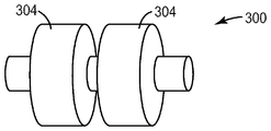
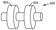
일련의 이중-챔버 음향 장치들이 도 5a 내지 도 5d에 도시되어 있다. 도시된 대안 구성들의 각각에서는, 추가의 팽창 챔버가 음향 장치에 통합되었다. 도 5a는, 음향 장치들(100, 200)과 동일한 전체 길이를 갖지만 각각이 팽창 챔버들(104, 204)의 길이의 절반보다 작은 한 쌍의 팽창 챔버들(304, 304)을 포함하는 음향 장치(300)를 도시한다. 도 5b 및 도 5c는 비대칭인 각각의 팽창 챔버들(404, 504)을 갖는 음향 장치들(400, 500)을 도시한다. 음향 장치(400)에서는, 입구에 인접한 팽창 챔버(404)가 더 길고; 음향 장치(500)에서는, 출구에 인접한 팽창 챔버(504)가 더 길다. 도 5d는, 동일한 크기를 갖지만 더 짧고 그리고 서로 더 멀리 떨어져 있는 팽창 챔버들(604)을 갖는 음향 장치(600)를 도시한다. 이러한 장치들 각각은 상이한 음향 주파수 범위에 걸쳐 소음을 감쇠시키도록 조정된다.A series of dual-chamber acoustic devices are shown in Figures 5A-5D. In each of the alternative arrangements shown, a further expansion chamber is incorporated in the acoustic device. 5A shows an
여기에 예시되지는 않았지만, 특정 주파수 범위에 걸쳐 음향 에너지를 추가로 감쇠시키기 위해 추가의 팽창 챔버들이 추가될 수 있다(제3, 제4 등). 또한, 인접한 챔버들 사이의 간격은 제로(0)로 감소될 수 있으며, 이 경우에, 주변 챔버는 그 길이를 따라 다수의 환형 세그먼트들로 간단하게 세분된다.Although not illustrated here, additional expansion chambers may be added (third, fourth, etc.) to further attenuate acoustic energy over a particular frequency range. In addition, the spacing between adjacent chambers may be reduced to zero, in which case the peripheral chamber is simply subdivided into a plurality of annular segments along its length.
제한하고자 의도한 것은 아니지만, 추가의 예시적인 실시 형태들이 다음과 같이 기술된다:Although not intended to be limiting, additional exemplary embodiments are described as follows:
1. 입구 및 출구를 갖는 음향 장치로서, 팽창 챔버를 한정하는 외부 하우징; 및 팽창 챔버를 통해 연장되고 팽창 챔버를 중앙 챔버와 중앙 챔버에 인접한 주변 챔버로 구획하는 관형 벽을 포함하고, 입구 및 출구 양쪽 모두는 중앙 챔버와 연통하고, 관형 벽은 중앙 챔버와 주변 챔버 사이의 공기 유동을 허용하도록 관통 형성되는 복수의 개구를 포함하며, 복수의 개구는 100 MKS 레일 내지 5000 MKS 레일 범위의 평균 유동 저항을 제공하도록 구성되는 음향 장치.One. An acoustic apparatus having an inlet and an outlet, the acoustic apparatus comprising: an outer housing defining an expansion chamber; And a tubular wall extending through the expansion chamber and partitioning the expansion chamber into a central chamber and a peripheral chamber adjacent the central chamber, both the inlet and the outlet communicating with the central chamber and the tubular wall extending between the central chamber and the peripheral chamber The plurality of openings being configured to provide an average flow resistance in the range of 100 MKS rails to 5000 MKS rails.
2. 실시 형태 1에 있어서, 복수의 개구는 250 MKS 레일 내지 3000 MKS 레일 범위의 평균 유동 저항을 제공하도록 구성되는 음향 장치.2. The acoustic device of embodiment 1, wherein the plurality of apertures are configured to provide an average flow resistance in the range of 250 to 3000 MKS rails.
3.
실시 형태 2에 있어서, 복수의 개구는 500 MKS 레일 내지 2000 MKS 레일 범위의 평균 유동 저항을 제공하도록 구성되는 음향 장치.3.
The acoustic device of
4. 실시 형태 1 내지 3 중 어느 하나에 있어서, 개구는 10 마이크로미터 내지 250 마이크로미터 범위의 평균 최소 직경을 갖는 음향 장치.4. The acoustic device as in any one of embodiments 1-3, wherein the opening has an average minimum diameter in the range of 10 micrometers to 250 micrometers.
5.
실시 형태 4에 있어서, 개구는 20 마이크로미터 내지 200 마이크로미터 범위의 평균 최소 직경을 갖는 음향 장치.5.
The acoustic device of
6.
실시 형태 5에 있어서, 개구는 30 마이크로미터 내지 150 마이크로미터 범위의 평균 최소 직경을 갖는 음향 장치.6.
The acoustic device of
7. 실시 형태 1 내지 6 중 어느 하나에 있어서, 관형 벽은 50 마이크로미터 내지 625 마이크로미터 범위의 두께를 갖는 음향 장치.7. 7. The acoustic device as in any one of embodiments 1-6, wherein the tubular wall has a thickness in the range of 50 micrometers to 625 micrometers.
8. 실시 형태 7에 있어서, 관형 벽은 75 마이크로미터 내지 575 마이크로미터 범위의 두께를 갖는 음향 장치.8. The apparatus of embodiment 7, wherein the tubular wall has a thickness in the range of 75 micrometers to 575 micrometers.
9. 실시 형태 8에 있어서, 관형 벽은 150 마이크로미터 내지 500 마이크로미터 범위의 두께를 갖는 음향 장치.9. The acoustic device of embodiment 8, wherein the tubular wall has a thickness in the range of 150 micrometers to 500 micrometers.
10. 실시 형태 1 내지 9 중 어느 하나에 있어서, 관형 벽은 0.3% 내지 5% 범위의 다공도를 갖는 음향 장치.10. The acoustic device as in any one of embodiments 1-9, wherein the tubular wall has a porosity in the range of 0.3% to 5%.
11.
실시 형태 10에 있어서, 관형 벽은 0.3% 내지 3.5% 범위의 다공도를 갖는 음향 장치.11.
The apparatus of
12. 실시 형태 11에 있어서, 관형 벽은 0.3% 내지 2% 범위의 다공도를 갖는 음향 장치.12. 11. The acoustic device of embodiment 11, wherein the tubular wall has a porosity in the range of 0.3% to 2%.
13. 실시 형태 1 내지 12 중 어느 하나에 있어서, 관형 벽은 0.2 GPa 내지 10 GPa 범위의 모듈러스를 갖는 재료를 포함하는 음향 장치.13. The acoustic device as in any one of embodiments 1-12, wherein the tubular wall comprises a material having a modulus in the range of 0.2 GPa to 10 GPa.
14. 실시 형태 13에 있어서, 관형 벽은 0.2 GPa 내지 5 GPa 범위의 모듈러스를 갖는 재료를 포함하는 음향 장치.14. The acoustic device of embodiment 13, wherein the tubular wall comprises a material having a modulus in the range of 0.2 GPa to 5 GPa.
15. 실시 형태 14에 있어서, 관형 벽은 0.2 GPa 내지 4 GPa 범위의 모듈러스를 갖는 재료를 포함하는 음향 장치.15. The acoustic device of embodiment 14, wherein the tubular wall comprises a material having a modulus in the range of 0.2 GPa to 4 GPa.
16. 실시 형태 1 내지 15 중 어느 하나에 있어서, 주변 챔버 및 중앙 챔버는 동심인 음향 장치.16. 17. The acoustic device of any one of embodiments 1-15, wherein the peripheral chamber and the central chamber are concentric.
17. 실시 형태 1 내지 16 중 어느 하나에 있어서, 관형 벽은 팽창 챔버에만 연관된 압력 강하에 비해 170 리터/분의 유량에서 입구로부터 출구로의 압력 강하를 적어도 20% 감소시키는 음향 장치.17. The acoustic device as in any one of embodiments 1-16, wherein the tubular wall reduces the pressure drop from inlet to outlet at a flow rate of 170 liters / minute relative to a pressure drop associated with the expansion chamber only by at least 20%.
18. 실시 형태 17에 있어서, 관형 벽은 팽창 챔버에만 연관된 압력 강하에 비해 압력 강하를 적어도 50% 감소시키는 음향 장치.18. The apparatus of embodiment 17 wherein the tubular wall reduces the pressure drop by at least 50% relative to the pressure drop associated with the expansion chamber only.
19.
실시 형태 18에 있어서, 관형 벽은 팽창 챔버에만 연관된 압력 강하에 비해 압력 강하를 적어도 70% 감소시키는 음향 장치.19.
18. The acoustic device of
20. 실시 형태 1 내지 19 중 어느 하나에 있어서, 입구 및 출구는 대체로 관형 벽의 단면 직경과 매칭되는 단면 직경을 갖는 음향 장치.20. The acoustic device as in any one of embodiments 1-19, wherein the inlet and outlet generally have a cross-sectional diameter that matches the cross-sectional diameter of the tubular wall.
21. 실시 형태 1 내지 20 중 어느 하나에 있어서, 관형 벽이 팽창 챔버의 전체 길이를 따라 연장되는 음향 장치.21. [0065] [0062] 13. The acoustic device as in any one of embodiments 1-20, wherein the tubular wall extends along the entire length of the expansion chamber.
22. 실시 형태 1 내지 21 중 어느 하나에 있어서, 관형 벽이 팽창 챔버의 전체 길이의 50% 내지 99%를 따라 연장되는 음향 장치.22. The apparatus of any of embodiments 1-21, wherein the tubular wall extends along 50% to 99% of the total length of the expansion chamber.
23.
실시 형태 22에 있어서, 관형 벽이 팽창 챔버의 전체 길이의 60% 내지 95%를 따라 연장되는 음향 장치.23.
22. The acoustic device of
24. 실시 형태 23에 있어서, 관형 벽이 팽창 챔버의 전체 길이의 70% 내지 80%를 따라 연장되는 음향 장치.24. 23. The acoustic device of embodiment 23, wherein the tubular wall extends along 70% to 80% of the total length of the expansion chamber.
25. 실시 형태 1 내지 24 중 어느 하나에 있어서, 관형 벽은 제1 관형 벽이고, 개구는 제1 개구이고, 주변 챔버는 제1 주변 챔버이고, 제1 주변 챔버에 인접한 제2 주변 챔버를 한정하는 제2 관형 벽을 추가로 포함하고, 제2 관형 벽은 복수의 제1 개구의 것보다 훨씬 더 낮은 음향 전달 임피던스를 제공하도록 크기가 설정된 복수의 제2 개구를 갖는 음향 장치.25. A method as in any one of embodiments 1-24, wherein the tubular wall is a first tubular wall, the opening is a first opening, the peripheral chamber is a first peripheral chamber, and the second peripheral chamber The second tubular wall having a plurality of second openings sized to provide a sound transfer impedance much lower than that of the plurality of first openings.
26.
실시 형태 25에 있어서, 복수의 제2 개구는 100 MKS 레일 내지 5000 MKS 레일 범위의 평균 유동 저항을 제공하도록 크기가 설정되는 음향 장치.26.
The acoustic device of
27. 실시 형태 26에 있어서, 복수의 제2 개구는 250 MKS 레일 내지 3000 MKS 레일 범위의 평균 유동 저항을 제공하도록 크기가 설정되는 음향 장치.27. 26. The acoustic device of embodiment 26 wherein the plurality of second openings are sized to provide an average flow resistance in the range of 250 to 3000 MKS rails.
28. 실시 형태 27에 있어서, 복수의 제2 개구는 500 MKS 레일 내지 2000 MKS 레일 범위의 평균 유동 저항을 제공하도록 크기가 설정되는 음향 장치.28. 27. The acoustic device of embodiment 27, wherein the plurality of second openings are sized to provide an average flow resistance in the range of 500 MKS rails to 2000 MKS rails.
29. 실시 형태 1 내지 28 중 어느 하나에 있어서, 팽창 챔버는 제1 팽창 챔버이고, 외부 하우징은 제1 팽창 챔버의 모든 한계(limitation)를 갖는 제2 팽창 챔버를 추가로 포함하고, 제1 팽창 챔버의 출구는 제2 팽창 챔버의 입구와 연통하는 음향 장치.29. 27. A dispenser as in any one of embodiments 1-28, wherein the expansion chamber is a first expansion chamber and the outer housing further comprises a second expansion chamber having all the limitations of the first expansion chamber, And the outlet communicates with the inlet of the second expansion chamber.
30. 팽창 챔버를 한정하는 외부 하우징, 팽창 챔버를 통해 연장되고 팽창 챔버를 중앙 챔버와 중앙 챔버에 인접한 주변 챔버로 구획하는 관형 벽, 및 중앙 챔버의 대향 단부들과 연통하는 입구 및 출구를 갖는 음향 장치를 사용하여 공기 중의 음향 에너지를 감쇠시키는 방법으로서,30. An acoustic device having an outer housing defining an expansion chamber, a tubular wall extending through the expansion chamber and partitioning the expansion chamber into a central chamber and a peripheral chamber adjacent the central chamber, and an inlet and an outlet communicating with opposite ends of the central chamber, A method of attenuating acoustic energy in air using:
중앙 챔버를 통해 공기를 유동시키는 단계; 및Flowing air through the central chamber; And
관형 벽에 배치된 복수의 개구 - 복수의 개구는 100 MKS 레일 내지 5000 MKS 레일 범위의 평균 유동 저항을 제공함 - 를 통해 중앙 챔버로부터 음향 에너지를 지향시키는 단계를 포함하는 방법.Directing acoustic energy from the central chamber through the plurality of openings disposed in the tubular wall, the plurality of openings providing an average flow resistance in the range of 100 MKS rails to 5000 MKS rails.
31.
실시 형태 30에 있어서, 관형 벽은 팽창 챔버에만 연관된 압력 강하에 비해 170 리터/분의 유량에서 입구로부터 출구로의 압력 강하를 적어도 20% 감소시키는 방법.31.
The method of
32. 실시 형태 31에 있어서, 관형 벽은 팽창 챔버에만 연관된 압력 강하에 비해 170 리터/분의 유량에서 입구로부터 출구로의 압력 강하를 적어도 50% 감소시키는 방법.32. The method of embodiment 31 wherein the tubular wall reduces the pressure drop from inlet to outlet at a flow rate of at least 170 liters / minute relative to the pressure drop associated with the expansion chamber only by at least 50%.
33. 실시 형태 32에 있어서, 관형 벽은 팽창 챔버에만 연관된 압력 강하에 비해 170 리터/분의 유량에서 입구로부터 출구로의 압력 강하를 적어도 70% 감소시키는 방법.33. 32. The method of embodiment 32 wherein the tubular wall reduces the pressure drop from inlet to outlet at a flow rate of 170 liters / minute relative to the pressure drop associated with the expansion chamber only by at least 70%.
34. 실시 형태 30 내지 33 중 어느 하나에 있어서, 벽은 제1 벽이고, 개구는 제1 개구이고, 주변 챔버는 제1 주변 챔버이고: 제1 주변 챔버로부터 제1 주변 챔버를 경계짓는 제2 벽 내에 배치된 복수의 제2 개구를 통해 제1 주변 챔버에 인접한 제2 주변 챔버로 음향 에너지를 지향시켜서 제1 벽의 것보다 훨씬 더 낮은 전달 임피던스를 제2 벽에 제공하는 단계를 추가로 포함하는 방법.34. 32. The method as in any one of embodiments 30-33, wherein the wall is a first wall, the opening is a first opening, and the peripheral chamber is a first peripheral chamber: within a second wall bounding the first peripheral chamber from the first peripheral chamber Further comprising directing acoustic energy through a plurality of the disposed second openings to a second peripheral chamber adjacent to the first peripheral chamber to provide a transfer impedance much lower than that of the first wall to the second wall .
35. 실시 형태 34에 있어서, 제2 벽은 100 MKS 레일 내지 5000 MKS 레일 범위의 평균 유동 저항을 제공하는 방법.35. 34. The method of embodiment 34 wherein the second wall provides an average flow resistance in the range of 100 MKS rails to 5000 MKS rails.
36.
실시 형태 35에 있어서, 제2 벽은 250 MKS 레일 내지 3000 MKS 레일 범위의 평균 유동 저항을 제공하는 방법.36.
35. The method of
37. 실시 형태 36에 있어서, 제2 벽은 500 MKS 레일 내지 2000 MKS 레일 범위의 평균 유동 저항을 제공하는 방법.37. 36. The method of embodiment 36, wherein the second wall provides an average flow resistance in the range of 500 MKS rails to 2000 MKS rails.
실시예Example
테스트 방법Test method
음향 테스트Sound test
ASTM E2611 - 09(전달 행렬법에 기초한 음향 재료의 수직 입사 음향 전송율의 측정을 위한 표준 테스트 방법)에 개요가 서술된 절차를 따름으로써 미세천공 필름 또는 패널의 음향 특성을 측정할 수 있다. 이 절차로부터 수집된 데이터를 이용하여 음향 전송 손실을 얻을 수 있다.The acoustic properties of a microperforated film or panel can be measured by following the procedure outlined in ASTM E2611-09 (Standard Test Method for Measurement of Vertical Ingress Acoustic Transfer Rates of Acoustic Materials Based on Transfer Matrix Method). Acoustic transmission loss can be obtained using the data collected from this procedure.
이 데이터는 또한 필름의 전달 임피던스를 얻는 데 사용될 수 있다. 이 절차의 산출물(output)들 중 하나는 미세천공 필름의 양면에 대한 압력 및 음향 입자 속도에 관한 2 × 2 전달 행렬이다. 아래에 개요가 서술된 절차를 따름으로써, 전달 행렬의 요소들이 이어서 필름의 전달 임피던스를 계산하는 데 사용될 수 있다.This data can also be used to obtain the transfer impedance of the film. One of the outputs of this procedure is a 2x2 transfer matrix on pressure and acoustic particle velocity on both sides of the microporous film. By following the procedure outlined below, the elements of the transfer matrix can then be used to calculate the transfer impedance of the film.
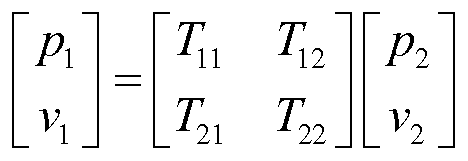
필름의 전면 및 후면 상에서의 압력과 속도 사이의 관계는 전달 행렬, 즉 하기 수학식 1을 이용하여 설명될 수 있다:The relationship between pressure and velocity on the front and back surfaces of the film can be described using a transfer matrix,
[수학식 1][Equation 1]
전달 임피던스를 계산하기 위해, 먼저 그 전면 속도 ![]()
![]()
![]()
![]()
[수학식 2]&Quot; (2) "
![]()
![]()
수학식 1로부터, ![]()
![]()
![]()
![]()
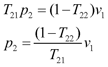
[수학식 3]&Quot; (3) "
![]()
![]()
[수학식 4]&Quot; (4) "
이어서, 수학식 3 및 수학식 4를 조작하여 다음의 결과를 얻을 수 있다:Then, by operating Equations (3) and (4), the following results can be obtained:
[수학식 5]&Quot; (5) "
![]()
![]()
[수학식 6]&Quot; (6) "
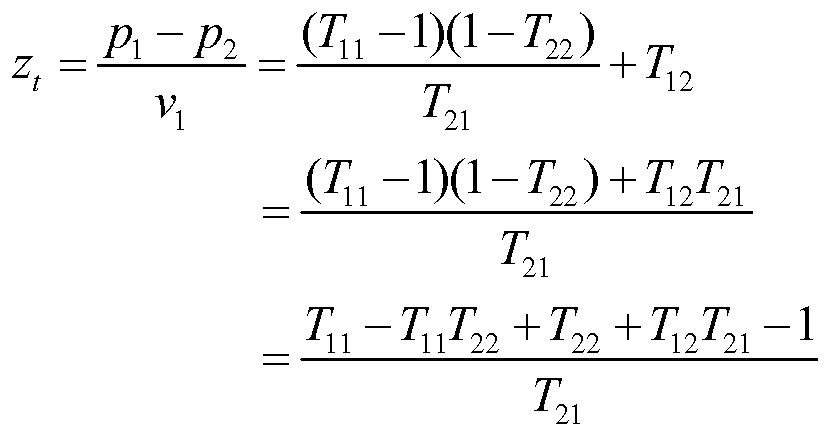
수학식 6을 수학식 5에 대입한 후, 수학식 7을 얻는다.After substituting Equation 6 into
[수학식 7]&Quot; (7) "
![]()
![]()
이어서, 수학식 7을 수학식 2에 대입함으로써 전달 임피던스가 얻어질 수 있다: 즉,Subsequently, transfer impedance can be obtained by substituting equation (7) into equation (2): < EMI ID =
[수학식 8]&Quot; (8) "
압력 강하 테스트Pressure Drop Test
압력 강하 측정치에 대한 기준(baseline)을 제공하기 위해, 어떠한 천공 필름도 갖지 않고 그리고 챔버를 형성하는 하우징 없이 별도의 음향 장치를 조립하였다. 오직 하나의 단부 캡을 사용하였고, 어떠한 챔버 또는 필름도 없이 기준 공기 유동 측정치로서 이러한 측정치를 제공(serve)하였다. 이어서, 이러한 기준 측정치를 도 8에 도시된 각각의 측정치로부터 감산하여, 도시된 압력 강하 곡선들이 기준에 비해 압력 강하 증가를 나타내도록 하였다.To provide a baseline for pressure drop measurements, a separate acoustic device was assembled without any apertured film and without a housing forming the chamber. Only one end cap was used and served as a reference air flow measurement without any chamber or film. This reference measurement was then subtracted from each of the measurements shown in FIG. 8 such that the pressure drop curves shown exhibit a pressure drop increase relative to the reference.
압력 강하 테스트의 경우, 10 psig 최대 출구를 갖는 NORGREN 레귤레이터, 모델 번호 11-018-146을 통해 제어 및 교축(throttle)되는 압축 공기의 사용에 의해 유동을 발생시켰다. 레귤레이터를 조절하여 유량을 변화시켰다. TSI 유동 게이지, 모델 4040을 통해 인라인으로 유량을 측정하였다. 그로부터, TSI VELOCICALC, 모델 8386A 압력 변환기를 이용하여 인라인 압력 측정을 위해 측면 탭을 갖는 직선 튜브를 통해 공기 유동을 지향시켰다.For the pressure drop test, flow was generated by the use of compressed air throttled and controlled through a NORGREN regulator with 10 psig maximum exit, Model No. 11-018-146. The flow rate was varied by regulating the regulator. Flow rates were measured in-line through a TSI flow gauge, Model 4040. From there, TSI VELOCICALC, Model 8386A pressure transducer was used to direct air flow through the straight tube with side taps for inline pressure measurement.
실시예 1(도 6: 52, 도 8: 64)Example 1 (Fig. 6: 52, Fig. 8: 64)
하기의 절차 및 재료를 이용하여 도 1 및 도 2에 개략적으로 도시된 음향 장치를 조립하였다. 블랙 아크릴로니트릴-부타디엔-스티렌(ABS) 수지(미국 미네소타주 에덴 프레이리(Eden Prairie) 소재의 Stratasys Ltd.)를 이용하여 급속 조형(rapid prototyping)(미국 미네소타주 에덴 프레이리 소재의 Stratasys Ltd., Fortus 400 모델 3D 프린터)을 통해, 챔버를 한정하는 원통형 외부 하우징을 제조하였다. 챔버의 길이는 9.6 cm였다. 하우징의 내경 및 외경은 각각 2.9 cm 및 15.2 cm였다. 또한, 급속 조형 및 블랙 ABS 수지를 이용하여 챔버에 대한 단부 캡들을 개별적으로 제조하였다. 단부 캡들은 시스템 공기가 음향 장치를 통해 유동할 수 있게 하는 2.9 cm 직경의 환형체를 포함하였다. 천공 필름의 튜브들을 포함시키기 위해 환형 홈들을 단부 캡의 설계에 통합하였다.The acoustic apparatus schematically illustrated in Figures 1 and 2 was assembled using the following procedures and materials. Rapid prototyping (Stratasys Ltd., Fortus, Eden Prairie, MN, USA) was performed using a black acrylonitrile-butadiene-styrene (ABS) resin (Stratasys Ltd., Eden Prairie, Minn. 400 model 3D printer), a cylindrical outer housing defining the chamber was fabricated. The length of the chamber was 9.6 cm. The inner and outer diameters of the housing were 2.9 cm and 15.2 cm, respectively. In addition, the end caps for the chamber were separately prepared using rapid molding and black ABS resin. The end caps included a 2.9 cm diameter annulus that allowed system air to flow through the acoustic device. The annular grooves were incorporated into the design of the end cap to include the tubes of the perforated film.
미국 특허 제6,617,002호(우드)에 기재된 바와 같이 천공 필름을 제조하였다. 필름-등급 폴리프로필렌 수지를 이용하여 필름을 압출하였다. 필름을 엠보싱 처리한 다음 그 엠보싱부를 열처리함으로써 압출 후에 필름을 천공하여 개구들을 생성하였다. 생성된 필름은 두께가 0.35 mm였고, 기본 중량이 약 400g/m2였으며, 개구/천공 밀도가 111 개구/㎠였고, 이때 각각의 개별 개구는 약 0.094 mm의 직경을 갖는 대략 원형의 형상이었다. 유동 저항은 약 450 MKS 레일인 것으로 판정되었다.A perforated film was prepared as described in U.S. Patent No. 6,617,002 (Wood). The film was extruded using a film-grade polypropylene resin. After the film was embossed and then the embossed portion was heat treated, the film was perforated after extrusion to create openings. The resulting film had a thickness of 0.35 mm, a basis weight of about 400 g / m 2 and an opening / puncture density of 111 openings /
천공 필름으로부터 개방 단부형 튜브를 제조하였고, 그 튜브는 길이가 9.7 cm이고 직경이 2.9 cm였다. 이어서, 튜브를 하우징 및 단부 캡 내의 환형 홈들에 삽입하여 중앙 챔버(112) 및 주변 챔버(114)를 형성하였다.An open ended tube was prepared from a perforated film, the tube having a length of 9.7 cm and a diameter of 2.9 cm. The tube was then inserted into the annular grooves in the housing and the end cap to form a
이러한 장치에 대한 음향 및 압력 강하 데이터가 도 6 및 도 8에 각각 제공되며, 이는 나타낸 바와 같다.Sound and pressure drop data for such a device are provided in Figures 6 and 8, respectively, as shown.
비교예 C1(도 6: 50, 도 8: 63)Comparative Example C1 (Fig. 6: 50, Fig. 8: 63)
어떠한 천공 필름도 없이 간단한 팽창 챔버를 나타내는 음향 장치를 상기 실시예 1에서와 같이 조립하였다.An acoustic device showing a simple expansion chamber without any perforated film was assembled as in Example 1 above.
이러한 장치에 대한 음향 및 압력 강하 데이터가 도 6 및 도 8에 각각 제공되며, 이는 나타낸 바와 같다.Sound and pressure drop data for such a device are provided in Figures 6 and 8, respectively, as shown.
실시예 2(도 8: 66)Example 2 (Fig. 8: 66)
상기 실시예 1에서와 같이 음향 장치를 조립하였다. 생성된 필름은 두께가 0.35 mm였고, 기본 중량이 약 400g/m2였으며, 개구 밀도가 46 개구/㎠였고, 평균 개구 직경이 약 0.077 mm였다. 유효 개구 직경은 실시예 1에 비해 감소되어 약 1750 MKS 레일의 정적 공기 유동 저항을 갖는 필름을 생성하였다.The acoustic apparatus was assembled as in the first embodiment. The resulting film had a thickness of 0.35 mm, a basis weight of about 400 g / m 2 , an aperture density of 46 aperture /
이러한 장치에 대한 압력 강하 데이터가 도 8에 제공되며, 이는 나타낸 바와 같다.Pressure drop data for such a device is provided in FIG. 8, which is shown.
실시예 3(도 6: 54)Example 3 (Fig. 6: 54)
도 4에 도시된 구성을 제공하기 위해 상이한 직경의 2개의 독립된 튜브들이 천공 필름으로부터 생성된 것을 제외하고는, 상기 실시예 1에서와 같이 음향 장치를 조립하였다. 튜브들을 하우징 및 단부 캡 내의 환형 홈들에 삽입하여 중앙 챔버(212) 및 제1 및 제2 주변 챔버들(214, 218)을 형성하였다. 2개의 동심 튜브들을 반경 방향을 따라 서로로부터 약 2.8 cm 이격시켰다.The acoustic device was assembled as in Example 1 except that two independent tubes of different diameters were produced from the perforated film to provide the configuration shown in FIG. The tubes were inserted into the annular grooves in the housing and the end cap to form the
이러한 장치에 대한 음향 데이터가 도 6에 제공되며, 이는 나타낸 바와 같다.Acoustic data for such a device is provided in Fig. 6, which is shown.
실시예 4(도 7: 58)Example 4 (Fig. 7: 58)
도 5c(공기는 왼쪽에서 오른쪽으로 흐르는 상태임)에 개략적으로 도시된 2개의 독립된 챔버들이 직렬로 사용된 것을 제외하고는, 상기 실시예 1에서와 같이 음향 장치를 조립하였다. 2개의 챔버들을 서로 유체 연통시켰고, 약 2 cm의 갭만큼 이격시켰다.The acoustic device was assembled as in Example 1 except that two independent chambers, schematically shown in Figure 5c (air flowing from left to right) were used in series. The two chambers were in fluid communication with each other and spaced apart by a gap of about 2 cm.
이러한 장치에 대한 음향 데이터가 도 7에 제공되며, 이는 나타낸 바와 같다.Acoustic data for such a device is provided in FIG. 7, which is shown.
비교예 C2(도 7: 56)Comparative Example C2 (Fig. 7: 56)
어떠한 천공 필름도 없는 것을 제외하고는, 상기 실시예 4에서와 같이 음향 장치를 조립하였다.The acoustic device was assembled as in Example 4, except that there was no perforated film.
이러한 장치에 대한 음향 데이터가 도 7에 제공되며, 이는 나타낸 바와 같다.Acoustic data for such a device is provided in FIG. 7, which is shown.
실시예 5(도 7: 60)Example 5 (Fig. 7: 60)
실시예 4에 도시된 바와 같이 2개의 독립된 챔버들이 직렬로 사용된 것을 제외하고는, 상기 실시예 3에서와 같이 음향 장치를 조립하였다. 2개의 챔버들을 약 2 cm의 갭만큼 서로로부터 이격시켰다.A sound device was assembled as in Example 3 except that two separate chambers were used in series as shown in Example 4. [ The two chambers were spaced from each other by a gap of about 2 cm.
실시예 3에서와 같이, 각각의 챔버에 천공 필름으로부터 생성된 직경이 상이한 한 쌍의 동심 튜브들을 포함시켰고, 이때 동심 튜브들 중 더 큰 튜브를 반경 방향을 따라 보다 작은 튜브로부터 약 2.8 cm 이격시켰다.As in Example 3, each chamber contained a pair of concentric tubes of different diameter produced from the perforated film, wherein the larger of the concentric tubes was spaced about 2.8 cm from the smaller tube along the radial direction .
이러한 장치에 대한 음향 데이터가 도 7에 제공되며, 이는 나타낸 바와 같다.Acoustic data for such a device is provided in FIG. 7, which is shown.
비교예 C3(도 8: 67)Comparative Example C3 (Fig. 8: 67)
무공형 비천공 필름이 천공 필름을 대체한 것을 제외하고는, 실시예 1에서와 같이 음향 장치를 조립하였다.The acoustic device was assembled as in Example 1, except that the non-porous non-perforated film replaced the perforated film.
이러한 장치에 대한 압력 강하 데이터가 도 8에 제공되며, 이는 나타낸 바와 같다.Pressure drop data for such a device is provided in FIG. 8, which is shown.
전술된 모든 특허 및 특허 출원들은 이로써 명시적으로 참고로 포함된다. 본 명세서의 발명이 특정 실시 형태와 관련하여 기재되었더라도, 이들 실시 형태는 단지 본 발명의 원리 및 적용을 예시할 뿐임을 이해하여야 한다. 당업자는, 본 발명의 사상 및 범주를 벗어나지 않으면서, 본 발명의 방법 및 장치에 다양한 변형 및 수정이 이루어질 수 있음을 알게 될 것이다. 따라서, 본 발명은 첨부된 청구범위 및 그의 등가물의 범주 내에 있는 수정 및 변형을 포함하고자 한다.All of the foregoing patents and patent applications are hereby expressly incorporated by reference. While the invention herein has been described with reference to particular embodiments, it is to be understood that these embodiments are merely illustrative of the principles and applications of the invention. It will be apparent to those skilled in the art that various modifications and variations can be made in the method and apparatus of the present invention without departing from the spirit or scope of the invention. Accordingly, the invention is intended to embrace all such alterations and modifications as fall within the scope of the appended claims and their equivalents.
Claims (15)
팽창 챔버를 한정하는 외부 하우징; 및
팽창 챔버를 통해 연장되고 팽창 챔버를 중앙 챔버와 중앙 챔버에 인접한 주변 챔버로 구획하는 관형 벽을 포함하고,
입구 및 출구 양쪽 모두는 중앙 챔버와 연통하며,
관형 벽은 중앙 챔버와 주변 챔버 사이의 공기 유동을 허용하도록 관통 형성되는 복수의 개구를 포함하며, 복수의 개구는 100 MKS 레일(Rayl) 내지 5000 MKS 레일 범위의 평균 유동 저항을 제공하도록 구성되는 음향 장치.An acoustic apparatus having an inlet and an outlet,
An outer housing defining an expansion chamber; And
A tubular wall extending through the expansion chamber and partitioning the expansion chamber into a central chamber and a peripheral chamber adjacent the central chamber,
Both the inlet and the outlet communicate with the central chamber,
The tubular wall includes a plurality of openings formed therethrough to allow air flow between the central chamber and the peripheral chamber, wherein the plurality of openings comprise an acoustic structure configured to provide an average flow resistance in the range of 100 MKS rails to 5000 MKS rails Device.
제1 주변 챔버에 인접한 제2 주변 챔버를 한정하는 제2 관형 벽을 추가로 포함하고,
제2 관형 벽은 복수의 제1 개구의 것보다 훨씬 더 낮은 음향 전달 임피던스를 제공하도록 크기가 설정된 복수의 제2 개구를 갖는 음향 장치.10. A method according to any one of claims 1 to 9, wherein the tubular wall is a first tubular wall, the opening is a first opening, the peripheral chamber is a first peripheral chamber,
Further comprising a second tubular wall defining a second peripheral chamber adjacent the first peripheral chamber,
The second tubular wall having a plurality of second openings sized to provide a sound transfer impedance much lower than that of the plurality of first openings.
중앙 챔버를 통해 공기를 유동시키는 단계; 및
관형 벽에 배치된 복수의 개구 - 복수의 개구는 100 MKS 레일 내지 5000 MKS 레일 범위의 평균 유동 저항을 제공함 - 를 통해 중앙 챔버로부터 음향 에너지를 지향시키는 단계를 포함하는 방법.An acoustic device having an outer housing defining an expansion chamber, a tubular wall extending through the expansion chamber and partitioning the expansion chamber into a central chamber and a peripheral chamber adjacent the central chamber, and an inlet and an outlet communicating with opposite ends of the central chamber, A method of attenuating acoustic energy in air using:
Flowing air through the central chamber; And
Directing acoustic energy from the central chamber through the plurality of openings disposed in the tubular wall, the plurality of openings providing an average flow resistance in the range of 100 MKS rails to 5000 MKS rails.
Applications Claiming Priority (3)
| Application Number | Priority Date | Filing Date | Title |
|---|---|---|---|
| US201462048153P | 2014-09-09 | 2014-09-09 | |
| US62/048,153 | 2014-09-09 | ||
| PCT/US2015/049111 WO2016040431A1 (en) | 2014-09-09 | 2015-09-09 | Acoustic device |
Publications (1)
| Publication Number | Publication Date |
|---|---|
| KR20170052629A true KR20170052629A (en) | 2017-05-12 |
Family
ID=54186297
Family Applications (1)
| Application Number | Title | Priority Date | Filing Date |
|---|---|---|---|
| KR1020177009228A KR20170052629A (en) | 2014-09-09 | 2015-09-09 | Acoustic device |
Country Status (7)
| Country | Link |
|---|---|
| US (1) | US10352210B2 (en) |
| EP (1) | EP3192068A1 (en) |
| JP (1) | JP6625118B2 (en) |
| KR (1) | KR20170052629A (en) |
| CN (1) | CN106715849B (en) |
| BR (1) | BR112017004638A2 (en) |
| WO (1) | WO2016040431A1 (en) |
Families Citing this family (21)
| Publication number | Priority date | Publication date | Assignee | Title |
|---|---|---|---|---|
| DE102015214709A1 (en) * | 2015-07-31 | 2017-02-02 | Mahle International Gmbh | Flow channel and ventilation, heating or air conditioning |
| WO2019005858A1 (en) * | 2017-06-28 | 2019-01-03 | 3M Innovative Properties Company | Microperforated conduit |
| JP6377867B1 (en) * | 2017-07-05 | 2018-08-22 | 富士フイルム株式会社 | Silencer system |
| JP6377868B1 (en) * | 2017-07-05 | 2018-08-22 | 富士フイルム株式会社 | Silencer system |
| EP3651150B1 (en) | 2017-07-05 | 2023-12-06 | FUJIFILM Corporation | Sound-damping system |
| US20190120414A1 (en) * | 2017-10-23 | 2019-04-25 | Hamilton Sundstrand Corporation | Duct assembly having internal noise reduction features, thermal insulation and leak detection |
| GB2568055B (en) * | 2017-11-02 | 2023-02-01 | Brush Elec Machines | Air outlet sound absorber for a rotating electrical machine |
| DE102017126125A1 (en) * | 2017-11-08 | 2019-05-09 | Dietrich Denker | Device for lowering airborne and structure-borne noise |
| CN108223383A (en) * | 2018-02-08 | 2018-06-29 | 珠海格力电器股份有限公司 | Pressure fluctuation attenuating device, compressor and air conditioner |
| CN108843435A (en) * | 2018-06-12 | 2018-11-20 | 蒙城县傲尊电子科技有限公司 | A kind of potent noise reduction automobile exhaust pipe |
| CN108961957A (en) * | 2018-07-25 | 2018-12-07 | 王小兰 | A kind of noise reduction apparatus for demonstrating |
| EP3850197A4 (en) * | 2018-09-13 | 2022-04-06 | The University of Adelaide | An exhaust gas assembly |
| US11592205B2 (en) * | 2018-12-18 | 2023-02-28 | Johnson Controls Tyco IP Holdings LLP | Silencer assembly for air handling unit of an HVAC system |
| CN112443433B (en) * | 2019-09-05 | 2024-02-27 | 上海索菲玛汽车滤清器有限公司 | Air filter |
| JP7092810B2 (en) * | 2020-02-12 | 2022-06-28 | フタバ産業株式会社 | Silencer |
| DE102020106017B3 (en) * | 2020-03-05 | 2021-07-29 | Umfotec Gmbh | Fluid flow conduit silencer and method of making the same |
| US11417311B2 (en) | 2020-08-03 | 2022-08-16 | W. L. Gore & Associates, Inc. | Acoustically resistive supported membrane assemblies including at least one support structure |
| US11776521B2 (en) | 2020-12-11 | 2023-10-03 | Toyota Motor Engineering & Manufacturing North America, Inc. | Sound absorbing structure having one or more acoustic scatterers attached to or forming a vehicle structure |
| CN114802043B (en) * | 2022-06-27 | 2022-09-23 | 质子汽车科技有限公司 | Vehicle cab and vehicle |
| CN115419529B (en) * | 2022-08-29 | 2024-01-16 | 岚图汽车科技有限公司 | Muffler assembly and noise verification method |
| CN116357479B (en) * | 2023-03-21 | 2023-09-29 | 北京航天试验技术研究所 | Silencer and noise reduction system |
Family Cites Families (29)
| Publication number | Priority date | Publication date | Assignee | Title |
|---|---|---|---|---|
| US3396813A (en) * | 1967-04-26 | 1968-08-13 | Oldberg Mfg Company | Silencer or muffler and method of producing same |
| US3920095A (en) * | 1974-02-01 | 1975-11-18 | Brunswick Corp | Free flow sound attenuating device and method of using |
| US3955643A (en) * | 1974-07-03 | 1976-05-11 | Brunswick Corporation | Free flow sound attenuating device and method of making |
| US5162620A (en) * | 1989-11-28 | 1992-11-10 | Allied-Signal Inc. | Dual flow turbine engine muffler |
| CN2062891U (en) | 1990-03-17 | 1990-09-26 | 沈阳冶炼厂 | High efficient silencer with multiple chambers |
| US5498127A (en) | 1994-11-14 | 1996-03-12 | General Electric Company | Active acoustic liner |
| US6617002B2 (en) | 1998-07-24 | 2003-09-09 | Minnesota Mining And Manufacturing Company | Microperforated polymeric film for sound absorption and sound absorber using same |
| US6977109B1 (en) | 1998-07-24 | 2005-12-20 | 3M Innovative Properties Company | Microperforated polymeric film for sound absorption and sound absorber using same |
| GB2346413B (en) * | 1999-02-05 | 2003-08-13 | Komatsu Mfg Co Ltd | Exhaust silencer |
| US6598701B1 (en) * | 2000-06-30 | 2003-07-29 | 3M Innovative Properties Company | Shaped microperforated polymeric film sound absorbers and methods of manufacturing the same |
| US20030098200A1 (en) * | 2001-11-29 | 2003-05-29 | Allied International Corporation | Acoustical absorptive splitter |
| US6684842B1 (en) | 2002-07-12 | 2004-02-03 | Visteon Global Technologies, Inc. | Multi-chamber resonator |
| EP1953354A1 (en) | 2003-08-11 | 2008-08-06 | ArvinMeritor Emissions Technologies GmbH | Exhaust silencer |
| EP2851526B1 (en) * | 2003-08-11 | 2018-05-23 | Faurecia Emissions Control Technologies, Germany GmbH | Exhaust Silencer |
| US20070157598A1 (en) * | 2005-08-22 | 2007-07-12 | Gagov Atanas | Plastic components formed from 3D blow molding |
| ES2355740T3 (en) * | 2006-01-06 | 2011-03-30 | Yamaha Hatsudoki Kabushiki Kaisha | MUFFLER AND VEHICLE EQUIPPED WITH THE MUFFLER. |
| JP4724611B2 (en) | 2006-01-06 | 2011-07-13 | ヤマハ発動機株式会社 | Muffler and vehicle with muffler |
| US7730996B2 (en) * | 2006-04-12 | 2010-06-08 | Ocv Intellectual Capital, Llc | Long fiber thermoplastic composite muffler system with integrated crash management |
| CN201367931Y (en) * | 2009-01-12 | 2009-12-23 | 昆明通晟汽车配件有限责任公司 | Impedance composite high-efficient engine muffler |
| CN201433804Y (en) | 2009-07-11 | 2010-03-31 | 张勇 | Wave-shaped micro-perforated plate muffler |
| DE102010002112A1 (en) * | 2010-02-18 | 2011-08-18 | Behr GmbH & Co. KG, 70469 | Air stream channel for use in heating, ventilation and/or air conditioning system of motor car, has grid arranged at jump discontinuity for partly covering jump discontinuity, where grid is designed as plastic grid, wire grid or metal sheet |
| KR101312387B1 (en) | 2011-04-18 | 2013-09-27 | 엔알텍주식회사 | Silencer of duct for air conditioner of train |
| US8505682B2 (en) | 2011-04-29 | 2013-08-13 | E I Du Pont De Nemours And Company | Lightweight polymeric exhaust components |
| US8424636B2 (en) * | 2011-04-29 | 2013-04-23 | E.I. Du Pont De Nemours And Company | Muffler assembly and process of manufacture |
| KR101693887B1 (en) | 2011-07-12 | 2017-01-06 | 현대중공업 주식회사 | Muffler with multi-resonator for construction equipment |
| CN202483685U (en) | 2012-03-23 | 2012-10-10 | 洛阳西苑车辆与动力检验所有限公司 | Three-cavity impedance combined air exhaust muffler of tractor |
| CN103321716B (en) | 2013-07-08 | 2015-09-16 | 山东大学 | The reactive muffler structure that a kind of perforated pipe and narrow slit resonant cavity combine |
| CN103671071A (en) | 2013-11-28 | 2014-03-26 | 武汉理工大学 | Double-layer series silencer with miniature perforated pipes |
| CN103670602B (en) * | 2013-11-28 | 2017-01-18 | 武汉理工大学 | Three-layer series micro-perforated pipe muffler |
-
2015
- 2015-09-09 BR BR112017004638A patent/BR112017004638A2/en active Search and Examination
- 2015-09-09 EP EP15767650.3A patent/EP3192068A1/en not_active Withdrawn
- 2015-09-09 JP JP2017513173A patent/JP6625118B2/en not_active Expired - Fee Related
- 2015-09-09 WO PCT/US2015/049111 patent/WO2016040431A1/en active Application Filing
- 2015-09-09 US US15/503,906 patent/US10352210B2/en not_active Expired - Fee Related
- 2015-09-09 KR KR1020177009228A patent/KR20170052629A/en unknown
- 2015-09-09 CN CN201580048123.5A patent/CN106715849B/en not_active Expired - Fee Related
Also Published As
| Publication number | Publication date |
|---|---|
| JP6625118B2 (en) | 2019-12-25 |
| WO2016040431A1 (en) | 2016-03-17 |
| US20170241310A1 (en) | 2017-08-24 |
| CN106715849A (en) | 2017-05-24 |
| BR112017004638A2 (en) | 2017-12-05 |
| JP2017534789A (en) | 2017-11-24 |
| CN106715849B (en) | 2019-10-22 |
| EP3192068A1 (en) | 2017-07-19 |
| US10352210B2 (en) | 2019-07-16 |
Similar Documents
| Publication | Publication Date | Title |
|---|---|---|
| KR20170052629A (en) | Acoustic device | |
| RU2311286C2 (en) | Acoustic shield for woodworking machine | |
| JP6246900B2 (en) | Ventilated or water-permeable soundproof wall having a sound insulation resonance chamber around the air passage or water passage | |
| Herrin et al. | Properties and applications of microperforated panels | |
| US11493232B2 (en) | Silencing system | |
| US11097828B2 (en) | Shroud | |
| KR20160043056A (en) | Sound wave guide for use in acoustic structures | |
| US11402123B2 (en) | Microperforated conduit | |
| US20200031200A1 (en) | Ventilating device for ventilating an interior of a motor vehicle | |
| Herrin et al. | A guide to the application of microperforated panel absorbers | |
| CN113096626A (en) | Silent box | |
| CN107355323A (en) | A kind of automotive air intake noise sound arrester | |
| JP2016133226A (en) | Noise eliminator of blower | |
| RU157128U1 (en) | COMBINED SILENCER OF AERODYNAMIC NOISE | |
| KR101979378B1 (en) | Splitter and sound attenuator including the same | |
| JP4727608B2 (en) | Intake silencer and silencer method | |
| CN210520895U (en) | Motor assembly for dust collector and dust collector | |
| CN112628517B (en) | Pipeline muffler, device and preparation method | |
| Liu | Enhancing microperforated panel absorption by subdividing the backing airspace into channels and resonators | |
| KR102107133B1 (en) | Soundproof wall with acoustic block | |
| SE525807C2 (en) | Noise reduction structure for air supply piping, has holes which are formed between each perforated panel at flow path side | |
| Bhattacharya | Flat Fresnel-spiral acoustic metamaterials composed of several arms ventilated metamaterials for simultaneous broadband sound absorption and air circulation | |
| CN115662377A (en) | Resonance unit of frequency modulation ultrathin, ultra-sparse and low-frequency noise elimination device and application thereof | |
| CN116543737A (en) | Muffler | |
| Vinberg | Compact, tuned silencer for vacuum cleaners |