KR20170051904A - Contact for Substrate Connector and Substrate Connector - Google Patents
Contact for Substrate Connector and Substrate Connector Download PDFInfo
- Publication number
- KR20170051904A KR20170051904A KR1020150153576A KR20150153576A KR20170051904A KR 20170051904 A KR20170051904 A KR 20170051904A KR 1020150153576 A KR1020150153576 A KR 1020150153576A KR 20150153576 A KR20150153576 A KR 20150153576A KR 20170051904 A KR20170051904 A KR 20170051904A
- Authority
- KR
- South Korea
- Prior art keywords
- contact
- guide
- substrate
- connecting member
- receiving groove
- Prior art date
Links
Images


Classifications
-
- H—ELECTRICITY
- H01—ELECTRIC ELEMENTS
- H01R—ELECTRICALLY-CONDUCTIVE CONNECTIONS; STRUCTURAL ASSOCIATIONS OF A PLURALITY OF MUTUALLY-INSULATED ELECTRICAL CONNECTING ELEMENTS; COUPLING DEVICES; CURRENT COLLECTORS
- H01R12/00—Structural associations of a plurality of mutually-insulated electrical connecting elements, specially adapted for printed circuits, e.g. printed circuit boards [PCB], flat or ribbon cables, or like generally planar structures, e.g. terminal strips, terminal blocks; Coupling devices specially adapted for printed circuits, flat or ribbon cables, or like generally planar structures; Terminals specially adapted for contact with, or insertion into, printed circuits, flat or ribbon cables, or like generally planar structures
- H01R12/70—Coupling devices
- H01R12/71—Coupling devices for rigid printing circuits or like structures
- H01R12/72—Coupling devices for rigid printing circuits or like structures coupling with the edge of the rigid printed circuits or like structures
- H01R12/73—Coupling devices for rigid printing circuits or like structures coupling with the edge of the rigid printed circuits or like structures connecting to other rigid printed circuits or like structures
- H01R12/732—Printed circuits being in the same plane
-
- H—ELECTRICITY
- H01—ELECTRIC ELEMENTS
- H01R—ELECTRICALLY-CONDUCTIVE CONNECTIONS; STRUCTURAL ASSOCIATIONS OF A PLURALITY OF MUTUALLY-INSULATED ELECTRICAL CONNECTING ELEMENTS; COUPLING DEVICES; CURRENT COLLECTORS
- H01R13/00—Details of coupling devices of the kinds covered by groups H01R12/70 or H01R24/00 - H01R33/00
- H01R13/62—Means for facilitating engagement or disengagement of coupling parts or for holding them in engagement
- H01R13/629—Additional means for facilitating engagement or disengagement of coupling parts, e.g. aligning or guiding means, levers, gas pressure electrical locking indicators, manufacturing tolerances
- H01R13/631—Additional means for facilitating engagement or disengagement of coupling parts, e.g. aligning or guiding means, levers, gas pressure electrical locking indicators, manufacturing tolerances for engagement only
Landscapes
- Coupling Device And Connection With Printed Circuit (AREA)
Abstract
Description
본 발명은 기판들 간의 전기적 연결을 위해 전자기기에 설치되는 기판 커넥터에 관한 것이다.The present invention relates to a substrate connector installed in an electronic apparatus for electrical connection between substrates.
일반적으로 커넥터(Connector)는 전기적 연결을 위해 각종 전자기기에 마련된다. 예컨대, 커넥터는 휴대폰, 컴퓨터, 태블릿 컴퓨터 등과 같은 전자기기에 설치되어서, 전자기기 내에 설치된 각종 부품을 서로 전기적으로 연결할 수 있다. 기판 커넥터는, 기판과 기판을 전기적으로 연결하는 커넥터이다.In general, a connector is provided in various electronic apparatuses for electrical connection. For example, the connector is installed in an electronic device such as a cellular phone, a computer, a tablet computer, etc., so that various components installed in the electronic device can be electrically connected to each other. The substrate connector is a connector for electrically connecting the substrate and the substrate.
도 1은 종래 기술에 따른 기판 커넥터에 있어서 접속부들이 서로 접속된 상태를 나타낸 개념도이다.1 is a conceptual view showing a state in which connection portions are connected to each other in a substrate connector according to a related art.
도 1을 참고하면, 종래 기술에 따른 기판 커넥터(10)는 제1기판에 연결되는 제1컨택트(11), 및 제2기판에 연결되는 제2컨택트(12)를 포함한다. 상기 제1컨택트(11) 및 상기 제2컨택트(12)는 서로 접촉되어서 전기적으로 연결된다. 이에 따라, 종래 기술에 따른 기판 커넥터(10)는 상기 제1기판 및 상기 제2기판을 서로 전기적으로 연결할 수 있다.Referring to FIG. 1, a
여기서, 종래 기술에 따른 기판 커넥터(10)는 상기 제1컨택트(11) 및 상기 제2컨택트(12)가 상호 간의 접촉에 의해서만 전기적 연결이 유지되므로, 상기 제1컨택트(11) 및 상기 제2컨택트(12)에 대한 조립 위치가 어긋나는 경우 오정렬(Mis-Alignment)로 인해 전기적 연결이 이루어지지 않는 문제가 있다. 이에 따라, 종래 기술에 따른 기판 커넥터(10)는 접촉 신뢰성 및 접촉 안정성이 저하되는 문제가 있다.Since the
한편, 최근에는 전자기기가 점차적으로 소형화됨에 따라 기판 커넥터(10)에 대해서도 소형화가 요구되고 있고, 이를 위해 상기 제1컨택트(11) 및 상기 제2컨택트(12) 또한 소형화되어 초협폭, 초협피치를 구현한다. 이에 따라, 종래 기술에 따른 기판 커넥터(10)는 오정렬이 발생할 가능성이 높아질 뿐만 아니라, 작은 진동, 흔들림 등에도 전기적 연결이 해제됨에 따라 접촉 신뢰성 및 접촉 안정성이 더욱 저하되는 문제가 있다.In recent years, the size of the
본 발명은 상술한 바와 같은 문제점을 해결하고자 안출된 것으로, 오정렬이 발생할 가능성을 감소시킬 수 있는 기판 커넥터용 컨택트 및 기판 커넥터를 제공하기 위한 것이다.SUMMARY OF THE INVENTION The present invention has been made to solve the above-mentioned problems, and it is an object of the present invention to provide a contact and a substrate connector for a substrate connector which can reduce the possibility of occurrence of misalignment.
본 발명은 초협폭, 초협피치 구현을 위해 소형화되더라도 접촉 신뢰성 및 접촉 안정성이 저하되는 것을 방지할 수 있는 기판 커넥터용 컨택트 및 기판 커넥터를 제공하기 위한 것이다.SUMMARY OF THE INVENTION The present invention is to provide a contact and a substrate connector for a substrate connector that can prevent deterioration of contact reliability and contact stability even if the substrate is miniaturized for ultra-narrow, ultra-pitch pitch implementation.
상술한 바와 같은 과제를 해결하기 위해, 본 발명은 다음과 같은 구성을 포함할 수 있다.In order to solve the above problems, the present invention may include the following configuration.
본 발명에 따른 기판 커넥터용 컨택트는 제1기판 및 제2기판 간의 전기적 연결을 위해 상기 제1기판에 실장되는 제1실장부재; 및 상기 제1실장부재에 결합되고, 상기 제2기판에 실장되는 제2기판용 컨택트에 접속되기 위한 제1접속부재를 포함할 수 있다. 상기 제1접속부재는 상기 제2기판용 컨택트를 수용하기 위한 수용홈, 상기 수용홈에 수용된 제2기판용 컨택트의 일측을 지지하기 위한 제1지지부재, 및 상기 수용홈에 수용된 제2기판용 컨택트의 타측을 지지하기 위한 제2지지부재를 포함할 수 있다.A contact for a substrate connector according to the present invention includes: a first mounting member mounted on the first substrate for electrical connection between a first substrate and a second substrate; And a first connecting member coupled to the first mounting member and connected to the second substrate contact mounted on the second substrate. The first connecting member includes a receiving groove for receiving the second substrate contact, a first supporting member for supporting one side of the second substrate contact accommodated in the receiving groove, and a second supporting member for supporting the second substrate, And a second support member for supporting the other side of the contact.
본 발명에 따른 기판 커넥터는 제1기판에 결합되기 위한 제1절연부재; 상기 제1절연부재에 결합되고, 상기 제1기판에 실장되기 위한 제1컨택트; 제2기판에 결합되기 위한 제2절연부재; 및 상기 제2절연부재에 결합되고, 상기 제2기판에 실장되기 위한 제2컨택트를 포함할 수 있다. 상기 제1컨택트는 상기 제1기판 및 상기 제2기판 간의 전기적 연결을 위해 상기 제2컨택트에 접속되는 제1접속부재를 포함할 수 있다. 상기 제1접속부재는 상기 제2컨택트를 수용하기 위한 수용홈, 상기 수용홈에 수용된 제2컨택트의 일측을 지지하기 위한 제1지지부재, 및 상기 수용홈에 수용된 제2컨택트의 타측을 지지하기 위한 제2지지부재를 포함할 수 있다.A board connector according to the present invention includes: a first insulating member for being coupled to a first substrate; A first contact coupled to the first insulating member and mounted on the first substrate; A second insulating member to be coupled to the second substrate; And a second contact coupled to the second insulating member and mounted on the second substrate. The first contact may include a first connecting member connected to the second contact for electrical connection between the first substrate and the second substrate. The first connecting member includes a receiving groove for receiving the second contact, a first supporting member for supporting one side of the second contact accommodated in the receiving groove, and a second supporting member for supporting the other side of the second contact accommodated in the receiving groove And a second support member for supporting the second support member.
본 발명에 따르면, 다음과 같은 효과를 도모할 수 있다.According to the present invention, the following effects can be achieved.
본 발명은 제1컨택트 및 제2컨택트 간의 정확한 접속 위치를 안내하도록 구현됨으로써, 제1컨택트 및 제2컨택트에 대해 오정렬이 발생할 가능성을 줄일 수 있고, 제1컨택트 및 제2컨택트에 대한 접촉 신뢰성 및 접촉 안정성을 향상시킬 수 있다.The present invention is embodied to guide the precise connection position between the first contact and the second contact, thereby reducing the possibility of misalignment with respect to the first contact and the second contact and reducing the contact reliability for the first contact and the second contact, The contact stability can be improved.
본 발명은 제1컨택트 및 제2컨택트를 접속된 상태로 유지시키기 위한 지지력을 갖추도록 구현됨으로써, 진동, 흔들림 등에 대한 내력을 증대시켜서 제1컨택트 및 제2컨택트 간의 접속이 진동, 흔들림 등으로 인해 해제되는 것을 방지할 수 있다.The present invention is embodied to have a supporting force for holding the first contact and the second contact in a connected state, thereby increasing the resistance against vibration, shaking, etc., so that the connection between the first contact and the second contact is prevented Can be prevented from being released.
본 발명은 제1컨택트 및 제2컨택트가 초협폭, 초협피치 구현을 위해 소형화되더라도 제1컨택트 및 제2컨택트에 대해 오정렬이 발생할 가능성을 줄일 수 있을 뿐만 아니라 진동, 흔들림 등에 대한 내력을 증대시킬 수 있으므로, 소형화된 전자기기에 대한 적용성을 향상시킬 수 있다.The present invention can reduce the possibility of misalignment of the first contact and the second contact but also increase the resistance to vibration and shaking even if the first contact and the second contact are miniaturized for realizing ultra narrow and ultra pitch pitch Therefore, the applicability to miniaturized electronic devices can be improved.
본 발명은 제1컨택트 및 제2컨택트가 서로 접속된 상태에서 폭을 감소시킬 수 있도록 구현됨으로써, 컴팩트한 구조로 구현될 수 있으므로 초협폭, 초협피치를 실현하는데 기여할 수 있다.The present invention can be implemented in a compact structure by reducing the width in a state where the first contact and the second contact are connected to each other, thereby contributing to realization of ultra-narrow and ultra-narrow pitches.
도 1은 종래 기술에 따른 기판 커넥터에 있어서 접속부들이 서로 접속된 상태를 나타낸 개념도
도 2는 본 발명에 따른 기판 커넥터에 대한 개략적인 결합 사시도
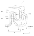
도 3은 도 2의 I-I 선을 기준으로 하는 본 발명에 따른 기판 커넥터의 개략적인 결합 단면도
도 4는 본 발명에 따른 기판 커넥터에 있어서 제1커넥터 및 제2커넥터에 대한 개략적인 사시도
도 5는 본 발명에 따른 기판 커넥터에 있어서 제1커넥터의 제1지지부재와 제2지지부재가 제2커넥터를 지지하는 모습을 나타낸 개략적인 평단면도
도 6은 본 발명에 따른 기판 커넥터에 있어서 제1절연부재 및 제1컨택트에 대한 개략적인 결합 사시도
도 7은 본 발명에 따른 기판 커넥터에 있어서 제1절연부재 및 제1컨택트에 대한 개략적인 분해 사시도
도 8은 본 발명에 따른 기판 커넥터에 있어서 제2절연부재 및 제2컨택트에 대한 개략적인 분해 사시도
도 9는 본 발명에 따른 기판 커넥터에 대한 개략적인 분해 사시도
도 10은 본 발명에 따른 기판 커넥터에 있어서 제1컨택트의 개략적인 사시도
도 11은 본 발명에 따른 기판 커넥터에 있어서 제1커넥터 및 제2커넥터를 도 4의 A 화살표 방향으로 바라본 모습을 나타낸 개략적인 정면도
도 12는 본 발명에 따른 기판 커넥터에 있어서 제1커넥터 및 제2커넥터를 도 11의 Ⅱ-Ⅱ 선을 기준으로 나타낸 개략적인 측단면도
도 13은 도 11의 Ⅱ-Ⅱ 선을 기준으로 본 발명에 따른 기판 커넥터에 있어서 제1커넥터 및 제2커넥터가 결합된 모습을 나타낸 개략적인 측단면도
도 14는 본 발명의 변형된 실시예에 따른 제1커넥터를 도 4의 A 화살표 방향으로 바라본 모습을 나타낸 개략적인 정면도
도 15는 본 발명에 따른 기판 커넥터에 있어서 제2컨택트의 개략적인 사시도1 is a conceptual view showing a state in which connection portions are connected to each other in a substrate connector according to the related art;
2 is a schematic perspective view of a substrate connector according to the present invention;
Figure 3 is a schematic cross-sectional view of the board connector according to the present invention with reference to line II in Figure 2;
4 is a schematic perspective view of a first connector and a second connector in a board connector according to the present invention;
5 is a schematic plan view showing a state in which the first and second support members of the first connector support the second connector in the board connector according to the present invention;
6 is a schematic perspective view of a first insulating member and a first contact in a board connector according to the present invention;
7 is a schematic exploded perspective view of the first insulating member and the first contact in the board connector according to the present invention;
8 is a schematic exploded perspective view of the second insulating member and the second contact in the board connector according to the present invention.
9 is a schematic exploded perspective view of a board connector according to the present invention.
Figure 10 is a schematic perspective view of a first contact in a board connector according to the present invention;
11 is a schematic front view showing a state in which the first connector and the second connector of the board connector according to the present invention are viewed in the direction of the arrow A in Fig.
12 is a schematic side sectional view of the board connector according to the present invention, in which the first connector and the second connector are shown with reference to the line II-II in Fig.
13 is a schematic side cross-sectional view showing a state in which the first connector and the second connector are coupled to each other in the board connector according to the present invention with reference to a line II-II in FIG.
14 is a schematic front view showing a state in which the first connector according to a modified embodiment of the present invention is viewed in the direction of arrow A in Fig.
Figure 15 is a schematic perspective view of a second contact in a board connector according to the present invention;
이하에서는 본 발명에 따른 기판 커넥터의 실시예를 첨부된 도면을 참조하여 상세히 설명한다. 본 발명에 따른 기판 커넥터용 컨택트는 본 발명에 따른 기판 커넥터에 포함되므로, 본 발명에 따른 기판 커넥터의 실시예를 설명하면서 함께 설명한다.Hereinafter, embodiments of a board connector according to the present invention will be described in detail with reference to the accompanying drawings. Since the contact for a board connector according to the present invention is included in the board connector according to the present invention, an embodiment of the board connector according to the present invention will be described together.
도 2 내지 도 4를 참고하면, 본 발명에 따른 기판 커넥터(1)는 휴대폰, 컴퓨터, 태블릿 컴퓨터 등과 같은 전자기기(미도시)에 설치된다. 본 발명에 따른 기판 커넥터(1)는 상기 전자기기에서 제1기판(100, 도 3에 도시됨) 및 제2기판(200, 도 3에 도시됨)을 전기적으로 연결하는 기능을 담당한다. 상기 제1기판(100) 및 상기 제2기판(200)은 인쇄회로기판(PCB, Printed Circuit Board)일 수 있다.2 to 4, the
본 발명에 따른 기판 커넥터(1)는 상기 제1기판(100)에 결합되기 위한 제1절연부재(2), 상기 제2기판(200)에 결합되기 위한 제2절연부재(3), 상기 제1절연부재(2)에 결합되는 제1컨택트(4), 및 상기 제2절연부재(3)에 결합되는 제2컨택트(5)를 포함한다.The
상기 제1컨택트(4)는 상기 제1기판(100)에 실장되어서 상기 제1기판(100)에 전기적으로 연결된다. 상기 제2컨택트(5)는 상기 제2기판(200)에 실장되어서 상기 제2기판(200)에 전기적으로 연결된다. 이에 따라, 상기 제2컨택트(5) 및 상기 제1컨택트(4)가 서로 접속되면, 상기 제1기판(100) 및 상기 제2기판(200)은 서로 전기적으로 연결된다.The
상기 제1컨택트(4)는 상기 제2컨택트(5)에 접속되기 위한 제1접속부재(41, 도 3에 도시됨)를 포함한다. 상기 제1접속부재(41)는 상기 제2컨택트(5)를 수용하기 위한 수용홈(411), 상기 수용홈(411)에 수용된 제2컨택트(5)의 일측(5a)을 지지하기 위한 제1지지부재(412), 및 상기 수용홈(411)에 수용된 제2컨택트(5)의 타측(5b)을 지지하기 위한 제2지지부재(413)를 포함한다.The
이에 따라, 상기 제1컨택트(4) 및 상기 제2컨택트(5)가 서로 접속되면, 도 4에 도시된 바와 같이 상기 제2컨택트(5)는 상기 수용홈(411)을 통해 상기 제1지지부재(412) 및 상기 제2지지부재(413)의 사이에 삽입된다. 상기 제1지지부재(412) 및 상기 제2지지부재(413)는 상기 수용홈(411)에 수용된 제2컨택트(5)의 양측(5a, 5b)을 지지한다. 따라서, 본 발명에 따른 기판 커넥터(1)는 다음과 같은 작용 효과를 도모할 수 있다.4, when the
첫째, 본 발명에 따른 기판 커넥터(1)는 상기 제2컨택트(5)가 상기 제1지지부재(412) 및 상기 제2지지부재(413)의 사이에 위치되도록 정렬되어야만 상기 제1절연부재(2) 및 상기 제2절연부재(3)가 원활하게 결합될 수 있으므로, 상기 제1지지부재(412) 및 상기 제2지지부재(413)를 통해 상기 제2컨택트(5) 및 상기 제1컨택트(4) 간의 정확한 접속 위치를 안내할 수 있다. 따라서, 본 발명에 따른 기판 커넥터(1)는 상기 제1컨택트(4) 및 상기 제2컨택트(5)에 대해 오정렬이 발생할 가능성을 줄임으로써, 상기 제1컨택트(4) 및 상기 제2컨택트(5)에 대한 접촉 신뢰성 및 접촉 안정성을 향상시킬 수 있다.First, the
둘째, 본 발명에 따른 기판 커넥터(1)는 상기 제1컨택트(4) 및 상기 제2컨택트(5)가 접속되면, 상기 제1지지부재(412) 및 상기 제2지지부재(413)가 상기 제2컨택트(5)의 양측(5a, 5b)을 지지하도록 구현된다. 따라서, 본 발명에 따른 기판 커넥터(1)는 진동, 흔들림 등에 대한 내력(耐力)를 증대시킴으로써, 접촉 신뢰성 및 접촉 안정성을 더 향상시킬 수 있다.Second, when the
셋째, 본 발명에 따른 기판 커넥터(1)는 상기 제1컨택트(4) 및 상기 제2컨택트(5)가 초협폭, 초협피지를 구현하기 위해 소형화되더라도, 상기 제1지지부재(412) 및 상기 제2지지부재(413)를 이용하여 오정렬이 발생할 가능성을 줄일 수 있을 뿐만 아니라 진동, 흔들림 등에 대한 내력을 증대시킬 수 있다. 따라서, 본 발명에 따른 기판 커넥터(1)는 소형화된 전자기기에 대한 적용성을 향상시킬 수 있다.Thirdly, even if the
넷째, 본 발명에 따른 기판 커넥터(1)는 상기 제2컨택트(5)가 상기 제1접속부재(41)에 형성된 수용홈(411)에 수용되므로, 상기 제2컨택트(5) 및 상기 제1컨택트(4)가 일부 중첩(重疊)된 상태로 서로 접속된다. 이에 따라, 본 발명에 따른 기판 커넥터(1)는 상기 제1컨택트(4) 및 상기 제2컨택트(5)가 서로 접속된 상태에서의 폭(W, 도 3에 도시됨)을 감소시킴으로써, 컴팩트한 구조로 구현될 수 있다.Fourthly, since the
이하에서는 상기 제1절연부재(2), 상기 제2절연부재(3), 상기 제1컨택트(4), 및 상기 제2컨택트(5)에 관해 첨부된 도면을 참고하여 구체적으로 설명한다.Hereinafter, the first insulating
도 2 내지 도 7을 참고하면, 상기 제1절연부재(2)는 상기 제1컨택트(4)를 지지한다. 상기 제1절연부재(2)에는 상기 제1컨택트(4)가 복수개 결합될 수 있다. 이 경우, 상기 제1컨택트(4)들은 제1축방향(X축 방향)을 따라 서로 이격되게 배치될 수 있다. 상기 제1절연부재(2)에는 상기 제1컨택트(4)들이 복수개의 열을 이루면서 상기 제1축방향(X축 방향)을 따라 서로 이격되게 배치될 수도 있다. 예컨대, 도 7에 도시된 바와 같이 상기 제1절연부재(2)에는 상기 제1컨택트(4)들이 2개의 열을 이루면서 상기 제1축방향(X축 방향)을 따라 서로 이격되게 배치될 수 있다.Referring to FIGS. 2 to 7, the first insulating
상기 제1절연부재(2)는 제1결합홈(21, 도 7에 도시됨)을 포함할 수 있다. 상기 제1결합홈(21)에는 상기 제1컨택트(4)가 결합된다. 상기 제1결합홈(21)은 상기 제1절연부재(2)의 측벽으로부터 소정 깊이 함몰되어 형성될 수 있다. 상기 제1컨택트(4)는 상기 제1결합홈(21)에 삽입되어서 상기 제1절연부재(2)에 결합될 수 있다. 상기 제1절연부재(2) 및 상기 제1컨택트(4)는 인서트 몰딩(Insert Molding)을 통해 결합될 수도 있다. 본 발명에 따른 기판 커넥터(1)가 상기 제1컨택트(4)를 복수개 포함하는 경우, 상기 제1절연부재(2)는 상기 제1결합홈(21)을 복수개 포함할 수 있다. 상기 제1결합홈(21)들은 복수개의 열을 이루면서 상기 제1축방향(X축 방향)을 따라 서로 이격되게 배치되도록 형성될 수 있다. 상기 제1절연부재(2)는 상기 제1컨택트(4)들의 개수와 동일한 개수의 제1결합홈(21)을 포함할 수 있다.The first insulating
상기 제1절연부재(2)는 제1안착홈(22, 도 6에 도시됨)을 포함할 수 있다. 상기 제1안착홈(22)에는 상기 제2절연부재(3)가 삽입된다. 상기 제1절연부재(2)는 상기 제2절연부재(3)가 상기 제1안착홈(22)에 삽입되도록 상기 제2절연부재(3)에 결합될 수 있다. 상기 제1안착홈(22)은 복수개의 열을 이루면서 배치된 제1결합홈(21)들의 사이에 위치하도록 형성될 수 있다.The first insulating
도 2 내지 도 8을 참고하면, 상기 제2절연부재(3)는 상기 제2컨택트(5)를 지지한다. 상기 제2절연부재(3)는 상기 제2컨택트(5)가 복수개 결합될 수 있다. 이 경우, 상기 제2컨택트(5)들은 상기 제1축방향(X축 방향)을 따라 서로 이격되게 배치될 수 있다. 상기 제2절연부재(3)에는 상기 제2컨택트(5)들이 복수개의 열을 이루면서 상기 제1축방향(X축 방향)을 따라 서로 이격되게 배치될 수도 있다. 예컨대, 도 5에 도시된 바와 같이 상기 제2절연부재(3)에는 상기 제2컨택트(5)들이 2개의 열을 이루면서 상기 제1축방향(X축 방향)을 따라 서로 이격되게 배치될 수 있다.Referring to FIGS. 2 to 8, the second insulating
상기 제2절연부재(3)는 제2결합홈(31, 도 8에 도시됨)을 포함할 수 있다. 상기 제2결합홈(31)에는 상기 제2컨택트(5)가 결합된다. 상기 제2결합홈(31)은 상기 제2절연부재(3)의 측벽으로부터 소정 깊이 함몰되어 형성될 수 있다. 상기 제2컨택트(5)는 상기 제2결합홈(31)에 삽입되어서 상기 제2절연부재(3)에 결합될 수 있다. 상기 제2절연부재(3) 및 상기 제2컨택트(5)는 인서트 몰딩을 통해 결합될 수도 있다. 본 발명에 따른 기판 커넥터(1)가 상기 제2컨택트(5)를 복수개 포함하는 경우, 상기 제2절연부재(3)는 상기 제2결합홈(31)을 복수개 포함할 수 있다. 상기 제2결합홈(31)들은 복수개의 열을 이루면서 상기 제1축방향(X축 방향)을 따라 서로 이격되게 배치되도록 형성될 수 있다. 상기 제2절연부재(3)는 상기 제2컨택트(5)들의 개수와 동일한 개수의 제2결합홈(31)을 포함할 수 있다.The second insulating
상기 제2절연부재(3)는 제2안착홈(32, 도 7에 도시됨), 및 안착돌기(33, 도 7에 도시됨)을 포함할 수 있다.The second insulating
상기 제2안착홈(32)에는 상기 제1절연부재(2) 및 상기 제1컨택트(4)가 삽입된다. 상기 제2절연부재(3)에는 상기 제1컨택트(4)가 결합된 제1절연부재(2)가 상기 제2안착홈(32)에 삽입되도록 결합될 수 있다. 상기 제2안착홈(32)은 내측에 상기 안착돌기(33)가 위치하도록 형성될 수 있다.The first insulating member (2) and the first contact (4) are inserted into the second seating groove (32). The first insulating
상기 안착돌기(33)는 상기 제2안착홈(32)의 내측에 위치하도록 형성된다. 상기 안착돌기(33)는 복수개의 열을 이루면서 배치된 제2결합홈(31)들의 사이에 위치하도록 형성될 수 있다. 상기 안착돌기(33)는 상기 제1절연부재(2)의 제1안착홈(22)에 삽입되어서 상기 제1절연부재(2)를 지지할 수 있다. 상기 안착돌기(33)는 상기 제2결합홈(31)에 결합된 제2컨택트(5)를 지지할 수 있다.And the
도 9에 도시된 바와 같이, 본 발명에 따른 기판 커넥터(1)는 상기 제2컨택트(5)가 결합된 제2절연부재(3) 및 상기 제1컨택트(4)가 결합된 제1절연부재(2)가 서로 결합됨으로써 구현될 수 있다. 상기 제1절연부재(2)는 상기 제1컨택트(4)의 제1접속부재(41)가 상기 제2절연부재(3)를 향하도록 배치된 상태에서 상기 제2절연부재(5)에 결합될 수 있다. 이 경우, 상기 제1절연부재(2) 및 상기 제2절연부재(5) 중에서 적어도 하나가 이동함으로써, 상기 제1절연부재(2) 및 상기 제2절연부재(5)가 결합될 수 있다.9, the
도 2 내지 도 11을 참고하면, 상기 제1컨택트(4)는 상기 제1절연부재(2, 도 6에 도시됨)에 결합된다. 상기 제1컨택트(4)는 복수개가 상기 제1절연부재(2)에 결합될 수 있다. 상기 제1컨택트(4)들은 복수개의 열을 이루면서 상기 제1축방향(X축 방향)으로 이격되게 상기 제1절연부재(2)에 결합될 수 있다. 상기 제1컨택트(4)들은 모두 동일한 형태 및 기능을 갖도록 구현되므로, 이하에서는 하나의 제1컨택트(4)를 기준으로 하여 구체적으로 설명한다.Referring to Figs. 2 to 11, the
상기 제1컨택트(4)는 상기 제1기판(100, 도 3에 도시됨)에 실장된다. 상기 제1컨택트(4)는 상기 제2기판(200, 도 3에 도시됨)에 실장된 제2컨택트(5)에 접속됨으로써, 상기 제1기판(100) 및 상기 제2기판(200)을 전기적으로 연결할 수 있다. 상기 제1컨택트(4)는 전도성(傳導性)을 갖는 재질로 형성될 수 있다.The
상기 제1컨택트(4)는 상기 제1접속부재(41)를 포함한다.The first contact (4) includes the first connecting member (41).
상기 제1접속부재(41)는 상기 제2컨택트(5)에 접속되기 위한 것이다. 상기 제1컨택트(4)는 상기 제1접속부재(41)가 상기 제1안착홈(22, 도 6에 도시됨)의 외측에 위치하도록 상기 제1절연부재(2)에 결합될 수 있다.The first connecting member (41) is for being connected to the second contact (5). The
도 9 내지 도 13을 참고하면, 상기 제1접속부재(41)는 상기 수용홈(411), 상기 제1지지부재(412), 및 상기 제2지지부재(413)를 포함한다.9 to 13, the first connecting
상기 수용홈(411)은 상기 제2컨택트(5)를 수용하기 위한 것이다. 상기 제1컨택트(4) 및 상기 제2컨택트(5)가 서로 접속되면, 상기 수용홈(411)에는 상기 제2컨택트(5)가 수용된다. 이에 따라, 본 발명에 따른 기판 커넥터(1)는 상기 제1컨택트(4) 및 상기 제2컨택트(5)가 일부 중첩된 상태로 서로 접속되도록 구현됨으로써, 상기 제1컨택트(4) 및 상기 제2컨택트(5)가 서로 접속된 상태에서의 폭(W, 도 3에 도시됨)을 감소시킬 수 있다. 상기 폭(W)은 상기 제1축방향(X축 방향)에 대해 수직한 제2축방향(Y축 방향)에 해당하는 길이이다. 이 경우, 본 발명에 따른 기판 커넥터(1)는 폭방향으로 컴팩트한 구조로 구현됨으로써, 초협폭이 요구되는 소형화된 전자기기에 대한 적용성을 향상시킬 수 있다.The receiving
상기 수용홈(411)는 상기 제1지지부재(412) 및 상기 제2지지부재(413)의 사이에 위치하도록 형성된다. 상기 수용홈(411)은 상기 제1접속부재(41)로부터 소정 깊이 함몰되어 형성될 수 있다. 상기 수용홈(411)은 전체적으로 사각 판형의 홈으로 형성될 수 있으나, 이에 한정되지 않으며 상기 제2컨택트(5)를 수용할 수 있는 형태이면 다른 형태로 형성될 수 있다.The receiving
상기 제1지지부재(412)는 상기 제2컨택트(5)를 지지하기 위한 것이다. 상기 제1지지부재(412)는 상기 수용홈(411)에 수용된 제2컨택트(5)의 일측(5a, 도 11에 도시됨)을 지지할 수 있다. 상기 제2컨택트(5)의 일측(5a)은, 상기 제1축방향(X축방향)을 기준으로 하는 상기 제2컨택트(5)의 양측면 중에서 어느 하나의 측면이다.The
상기 제2지지부재(413)는 상기 제2컨택트(5)를 지지하기 위한 것이다. 상기 제2지지부재(413)는 상기 수용홈(411)에 수용된 제2컨택트(5)의 타측(5b, 도 11에 도시됨)을 지지할 수 있다. 상기 제2컨택트(5)의 타측(5b)은, 상기 제1축방향(X축 방향)을 기준으로 상기 제2컨택트(5)의 일측(5a)에 대해 반대되는 측면이다.The
상기 제2지지부재(413) 및 상기 제1지지부재(412)는, 상기 제1축방향(X축 방향)으로 서로 이격되게 배치된다. 상기 제2지지부재(413) 및 상기 제1지지부재(412)의 사이에는, 상기 수용홈(411)이 위치한다. 이에 따라, 상기 제2지지부재(413) 및 상기 제1지지부재(412)는, 상기 수용홈(411)에 수용된 제2컨택트(5)의 양측(5a, 5b)을 지지함으로써, 상기 제2컨택트(5)가 상기 수용홈(411)에 수용된 상태에서 상기 제1축방향(X축 방향)으로 유동하는 것을 제한할 수 있다. 따라서, 본 발명에 따른 기판 커넥터(1)는 진동, 흔들림 등이 발생하더라도 상기 제2컨택트(5)가 상기 제1축방향(X축 방향)으로 유동하는 것을 방지함으로써, 진동, 흔들림 등으로 인해 상기 제2컨택트(5) 및 상기 제1컨택트(4) 간에 접속이 해제되는 것을 방지할 수 있다. 이에 따라, 본 발명에 따른 기판 커넥터(1)는 진동, 흔들림 등에 대한 내력를 증대시킴으로써, 접촉 신뢰성 및 접촉 안정성을 향상시킬 수 있다.The
상기 제2지지부재(413) 및 상기 제1지지부재(412)는, 상기 제1컨택트(4) 및 상기 제2컨택트(5) 간의 정확한 접속 위치를 안내할 수 있다. 상기 제2컨택트(5)가 상기 제2지지부재(413) 및 상기 제1지지부재(412)의 사이에 위치하도록 정렬되어야만, 상기 제1절연부재(2, 도 9에 도시됨) 및 상기 제2절연부재(3, 도 9에 도시됨)가 원활하게 결합될 수 있기 때문이다. 상기 제2컨택트(5)가 상기 제2지지부재(413) 및 상기 제1지지부재(412)의 사이로부터 벗어나서 오정렬된 경우, 상기 제1절연부재(2) 및 상기 제2절연부재(3)를 결합시키기 위해 과다한 힘을 가하여야 하므로, 이로부터 작업자는 상기 제2컨택트(5) 및 상기 제1컨택트(4)가 오정렬되었음을 확인할 수 있다. 또한, 작업자는 상기 제1절연부재(2) 및 상기 제2절연부재(3)를 결합시키는 과정에서 육안을 통해 상기 제2컨택트(5)가 상기 제2지지부재(413) 및 상기 제1지지부재(412)의 사이에 위치하도록 정렬되었는지 여부를 확인할 수 있다.The
따라서, 본 발명에 따른 기판 커넥터(1)는 상기 제2지지부재(413) 및 상기 제1지지부재(412)를 이용하여 상기 제1컨택트(4) 및 상기 제2컨택트(5) 간의 정확한 접속 위치를 안내함으로써, 상기 제1컨택트(4) 및 상기 제2컨택트(5)를 접속시키는 작업에 대한 정확성 및 용이성을 향상시킬 수 있다. 또한, 본 발명에 따른 기판 커넥터(1)는 상기 제1컨택트(4) 및 상기 제2컨택트(5)에 대해 오정렬이 발생할 가능성을 줄임으로써, 상기 제1컨택트(4) 및 상기 제2컨택트(5)에 대한 접촉 신뢰성 및 접촉 안정성을 향상시킬 수 있다.Therefore, the
도 10 내지 도 13을 참고하면, 상기 제1접속부재(41)는 제1가이드부재(414) 및 제2가이드부재(415)를 포함할 수 있다.Referring to FIGS. 10 to 13, the first connecting
상기 제1가이드부재(414)는 상기 제2컨택트(5)가 상기 수용홈(411)에 수용되도록 상기 제2컨택트(5)의 일측(5a)을 가이드한다. 상기 제1가이드부재(414)는 상기 제1지지부재(412)에 연결되게 형성될 수 있다. 상기 제1가이드부재(414) 및 상기 제1지지부재(412)는 일체로 형성될 수도 있다.The
상기 제2가이드부재(415)는 상기 제2컨택트(5)가 상기 수용홈(411)에 수용되도록 상기 제2컨택트(5)의 타측(5b)을 가이드한다. 상기 제2가이드부재(415)는 상기 제2지지부재(413)에 연결되게 형성될 수 있다. 상기 제2가이드부재(415) 및 상기 제2지지부재(413)는 일체로 형성될 수도 있다.The
상술한 바와 같이, 상기 제2가이드부재(415) 및 상기 제1가이드부재(414)는 상기 제2컨택트(5)의 양측(5a, 5b)을 가이드함으로써, 상기 제2컨택트(5)가 상기 제1지지부재(412) 및 상기 제2지지부재(413)의 사이에서 상기 수용홈(411)에 수용되도록 유도할 수 있다. 예컨대, 도 11에 도시된 바와 같이 상기 제1컨택트(4)가 상기 제2컨택트(5)의 상측에 위치한 상태에서 상기 제1컨택트(4)가 상기 제2컨택트(5) 쪽으로 이동하면, 상기 제2컨택트(5)는 상기 제2가이드부재(415) 및 상기 제1가이드부재(414)를 지나서 상기 제1지지부재(412) 및 상기 제2지지부재(413)의 사이에 위치하도록 상기 수용홈(411)에 수용될 수 있다. 이 경우, 상기 제2컨택트(5)는 일측(5a)이 상기 제1가이드부재(414)에 가이드되고, 타측(5b)이 상기 제2가이드부재(415)에 가이드됨으로써, 정확한 접속 위치로 안내될 수 있다.As described above, the
따라서, 본 발명에 따른 기판 커넥터(1)는 상기 제1가이드부재(414) 및 상기 제2가이드부재(415)를 이용하여 상기 제1컨택트(4) 및 상기 제2컨택트(5) 간의 정확한 접속 위치를 안내함으로써, 상기 제1컨택트(4) 및 상기 제2컨택트(5)를 접속시키는 작업에 대한 정확성 및 용이성을 더 향상시킬 수 있다. 또한, 본 발명에 따른 기판 커넥터(1)는 상기 제1컨택트(4) 및 상기 제2컨택트(5)에 대해 오정렬이 발생할 가능성을 더 줄임으로써, 상기 제1컨택트(4) 및 상기 제2컨택트(5)에 대한 접촉 신뢰성 및 접촉 안정성을 더 향상시킬 수 있다.Therefore, the
도 10 내지 도 13을 참고하면, 상기 제1접속부재(41)는 유도홈(416)을 포함할 수 있다.Referring to FIGS. 10 to 13, the first connecting
상기 유도홈(416)은 상기 제1가이드부재(414) 및 상기 제2가이드부재(415)의 사이에 위치하도록 형성된다. 상기 유도홈(416)은 상기 수용홈(411)에 연결되게 형성될 수 있다. 이에 따라, 상기 제2컨택트(5)는 상기 유도홈(416)을 통해 상기 제1가이드부재(414) 및 상기 제2가이드부재(415)를 지나서 상기 제1지지부재(412) 및 상기 제2지지부재(413)의 사이에 위치하도록 상기 수용홈(411)에 수용될 수 있다. 상기 유도홈(416)은 상기 제1접속부재(41)로부터 소정 깊이 함몰되어 형성될 수 있다.The
도 10 내지 도 14를 참고하면, 상기 제1가이드부재(414)는 제1가이드면(4141, 도 11에 도시됨)을 포함할 수 있다. 10 to 14, the
상기 제1가이드면(4141)은 상기 제2가이드부재(415)를 향하도록 배치된다. 상기 제1가이드면(4141)은 상기 제2컨택트(5)의 일측(5a)에 접촉되어서 상기 제2컨택트(5)가 상기 수용홈(411)에 수용되도록 상기 제2컨택트(5)의 일측(5a)을 가이드할 수 있다.The
상기 제1가이드면(4141)은 도 14에 도시된 바와 같이 제1방향(FD 화살표 방향)을 따라 상기 제2가이드부재(415)로부터 동일한 거리로 이격되도록 평면(平面)으로 형성될 수 있다. 상기 제1방향(FD 화살표 방향)은 상기 수용홈(411)에서 상기 유도홈(416)을 향하는 방향이다. 이 경우, 상기 제2컨택트(5)는 일측(5a)이 상기 제1가이드면(4141)에 접촉된 상태로 상기 제1가이드면(4141)을 따라 제2방향(SD 화살표 방향)으로 이동함으로써, 상기 수용홈(411)에 수용될 수 있다. 상기 제2방향(SD 화살표 방향)은, 상기 제1방향(FD 화살표 방향)에 대해 반대되는 방향이다.The
도 11에 도시된 바와 같이, 상기 제1가이드면(4141)은 상기 제1방향(FD 화살표 방향)을 향할수록 상기 제2가이드부재(415)로부터 이격된 거리가 증가하도록 경사지게 형성될 수도 있다. 이 경우, 상기 제1가이드면(4141)은 상기 제1방향(FD 화살표 방향)을 따라 평면으로 형성된 경우와 대비할 때, 다음과 같은 장점이 있다.11, the
첫째, 상기 제1가이드면(4141)은 상기 제1방향(FD 화살표 방향)을 향할수록 상기 제2가이드부재(415)로부터 이격된 거리가 증가하도록 경사지게 형성됨으로써, 상기 제1축방향(X축 방향)으로 상기 제1컨택트(4) 및 상기 제2컨택트(5)의 위치가 소정 범위 내에서 오정렬된 경우에 상기 제1컨택트(4) 및 상기 제2컨택트(5) 중에서 적어도 하나를 이동시켜서 상기 제1컨택트(4) 및 상기 제2컨택트(5)의 위치를 정렬할 수 있다. 예컨대, 도 11을 기준으로 하여 상기 제2컨택트(5)가 왼쪽으로 오정렬된 경우, 상기 제2컨택트(5)는 상기 제1가이드면(4141)에 접촉된 후에 상기 제1가이드면(4141)이 이루는 경사를 따라 오른쪽으로 이동하게 된다. 이에 따라, 상기 제2컨택트(5)는 상기 제1지지부재(412) 및 상기 제2지지부재(413)의 사이에서 상기 수용홈(411)에 수용될 수 있는 위치로 정렬될 수 있다. 따라서, 본 발명에 따른 기판 커넥터(1)는 상기 제1컨택트(4) 및 상기 제2컨택트(5)를 접속시키는 작업에 대한 정확성을 향상시킬 수 있다.First, the
둘째, 상기 제1가이드면(4141)이 상기 제1방향(FD 화살표 방향)을 향할수록 상기 제2가이드부재(415)로부터 이격된 거리가 증가하도록 경사지게 형성되면, 상기 유도홈(416)은 상기 제1방향(FD 화살표 방향)을 향할수록 크기가 증가하게 형성된다. 이에 따라, 본 발명에 따른 기판 커넥터(1)는 상기 제1컨택트(4)에서 상기 제2컨택트(5)가 삽입되기 위한 입구 면적의 크기를 증대시킴으로써, 상기 제1컨택트(4) 및 상기 제2컨택트(5)를 접속시키는 작업에 대한 용이성을 향상시킬 수 있다.Secondly, if the
도 10 내지 도 14를 참고하면, 상기 제2가이드부재(415)는 제2가이드면(4151, 도 11에 도시됨)을 포함할 수 있다. Referring to FIGS. 10 to 14, the
상기 제2가이드면(4151)은 상기 제1가이드부재(414)를 향하도록 배치된다. 상기 제2가이드면(4151)은 상기 제1가이드면(4141)을 향하도록 배치될 수 있다. 상기 제2가이드면(4151)은 상기 제2컨택트(5)의 타측(5b)에 접촉되어서 상기 제2컨택트(5)가 상기 수용홈(411)에 수용되도록 상기 제2컨택트(5)의 타측(5b)을 가이드할 수 있다.The
상기 제2가이드면(4151)은 도 14에 도시된 바와 같이 상기 제1방향(FD 화살표 방향)을 따라 상기 제1가이드면(4141)으로부터 동일한 거리로 이격되도록 평면으로 형성될 수 있다. 이 경우, 상기 제2컨택트(5)는 타측(5b)이 상기 제2가이드면(4151)에 접촉된 상태로 상기 제2가이드면(4151)을 따라 상기 제2방향(SD 화살표 방향)으로 이동함으로써, 상기 수용홈(411)에 수용될 수 있다.The
도 11에 도시된 바와 같이, 상기 제2가이드면(4151)은 상기 제1방향(FD 화살표 방향)을 향할수록 상기 제1가이드면(4141)으로부터 이격된 거리가 증가하도록 경사지게 형성될 수도 있다. 이 경우, 상기 제2가이드면(4151)은 상기 제1방향(FD 화살표 방향)을 따라 평면으로 형성된 경우와 대비할 때, 다음과 같은 장점이 있다.11, the
첫째, 상기 제2가이드면(4151)은 상기 제1방향(FD 화살표 방향)을 향할수록 상기 제1가이드면(4141)으로부터 이격된 거리가 증가하도록 경사지게 형성됨으로써, 상기 제1축방향(X축 방향)으로 상기 제1컨택트(4) 및 상기 제2컨택트(5)의 위치가 소정 범위 내에서 오정렬된 경우에 상기 제1컨택트(4) 및 상기 제2컨택트(5) 중에서 적어도 하나를 이동시켜서 상기 제1컨택트(4) 및 상기 제2컨택트(5)의 위치를 정렬할 수 있다. 예컨대, 도 11을 기준으로 하여 상기 제2컨택트(5)가 오른쪽으로 오정렬된 경우, 상기 제2컨택트(5)는 상기 제2가이드면(4151)에 접촉된 후에 상기 제2가이드면(4151)이 이루는 경사를 따라 왼쪽으로 이동하게 된다. 이에 따라, 상기 제2컨택트(5)는 상기 제1지지부재(412) 및 상기 제2지지부재(413)의 사이에서 상기 수용홈(411)에 수용될 수 있는 위치로 정렬될 수 있다. 따라서, 본 발명에 따른 기판 커넥터(1)는 상기 제1컨택트(4) 및 상기 제2컨택트(5)를 접속시키는 작업에 대한 정확성을 향상시킬 수 있다.The
둘째, 상기 제2가이드면(4151)이 상기 제1방향(FD 화살표 방향)을 향할수록 상기 제1가이드면(4141)으로부터 이격된 거리가 증가하도록 경사지게 형성되면, 상기 유도홈(416)은 상기 제1방향(FD 화살표 방향)을 향할수록 크기가 증가하게 형성된다. 이에 따라, 본 발명에 따른 기판 커넥터(1)는 상기 제1컨택트(4)에서 상기 제2컨택트(5)가 삽입되기 위한 입구 면적의 크기를 증대시킴으로써, 상기 제1컨택트(4) 및 상기 제2컨택트(5)를 접속시키는 작업에 대한 용이성을 향상시킬 수 있다.Second, if the
도 11에 도시된 바와 같이, 상기 제2가이드면(4151) 및 상기 제1가이드면(4141) 모두가 상기 제1방향(FD 화살표 방향)을 향할수록 서로 간의 간격이 벌어지도록 경사지게 형성될 수도 있다. 이 경우, 본 발명에 따른 기판 커넥터(1)는 상기 제1축방향(X축 방향)을 기준으로 상기 제1컨택트(4) 및 상기 제2컨택트(5)의 위치를 정렬할 수 있는 범위를 늘릴 수 있다. 또한, 본 발명에 따른 기판 커넥터(1)는 상기 제1컨택트(4)에서 상기 제2컨택트(5)가 삽입되기 위한 입구 면적의 크기를 더 증대시킬 수 있다. 따라서, 본 발명에 따른 기판 커넥터(1)는 상기 제1컨택트(4) 및 상기 제2컨택트(5)를 접속시키는 작업에 대한 정확성 및 용이성을 더 향상시킬 수 있다.11, both of the
도 10 내지 도 13을 참고하면, 상기 제1접속부재(41)는 유도면(417, 도 12에 도시됨)을 포함할 수 있다.10 to 13, the first connecting
상기 유도면(417)은 상기 제1가이드부재(414, 도 11에 도시됨) 및 상기 제2가이드부재(415, 도 11에 도시됨)의 사이에 위치한다. 상기 유도홈(417)은 상기 수용홈(411)을 기준으로 상기 제1방향(FD 화살표 방향) 쪽에 위치하도록 형성될 수 있다.The
상기 유도면(417)은 곡면(曲面)으로 형성될 수 있다. 도 12에 도시된 바와 같이, 상기 유도면(417)은 상기 제2축방향(Y축 방향)을 기준으로 곡면을 이루도록 형성될 수 있다. 이에 따라, 상기 유도면(417)은 상기 제2축방향(Y축 방향)으로 상기 제1컨택트(4) 및 상기 제2컨택트(5)의 위치가 소정 범위 내에서 오정렬된 경우에 상기 제1컨택트(4) 및 상기 제2컨택트(5) 중에서 적어도 하나를 이동시킴으로써, 상기 제2컨택트(5)가 상기 수용홈(411)에 수용되도록 유도할 수 있다. 예컨대, 도 12를 기준으로 하여 상기 제2컨택트(5)가 상기 제2축방향(Y축 방향)을 기준으로 오른쪽으로 오정렬된 경우, 상기 제2컨택트(5)는 상기 유도면(417)에 접촉된 후에 상기 유도면(417)이 이루는 곡면를 따라 왼쪽으로 이동하게 된다. 이에 따라, 상기 제2컨택트(5)는 상기 제1지지부재(412) 및 상기 제2지지부재(413)의 사이에서 상기 수용홈(411)에 수용될 수 있는 위치로 정렬되도록 유도될 수 있다. 따라서, 본 발명에 따른 기판 커넥터(1)는 상기 제1컨택트(4) 및 상기 제2컨택트(5)를 접속시키는 작업에 대한 정확성 및 용이성을 더 향상시킬 수 있다.The
도 10 내지 도 13을 참고하면, 상기 제1접속부재(41)는 접속면(418, 도 12에 도시됨), 및 제1걸림면(419, 도 12에 도시됨)을 포함할 수 있다.10 to 13, the first connecting
상기 접속면(418)은 상기 제1지지부재(412, 도 11에 도시됨) 및 상기 제2지지부재(413, 도 11에 도시됨)의 사이에 위치한다. 상기 접속면(418)은 상기 수용홈(411)에 수용된 제2컨택트(5)에 접속될 수 있다. 상기 제2접속면(418)은 상기 제2방향(SD 화살표 방향)으로 상기 유도면(417)으로부터 이격된 위치에 형성될 수 있다. 상기 접속면(418)은 평면을 이루도록 형성될 수 있다.The
상기 제1걸림면(419)은 상기 접속면(418) 및 상기 유도면(417) 사이에 위치한다. 상기 제1걸림면(419)은 상기 접속면(418)으로부터 돌출되게 형성된다. 이에 따라, 상기 제1걸림면(419)은 도 13에 도시된 바와 같이 상기 제2컨택트(5)가 상기 수용홈(411)에 수용되면 상기 제2컨택트(5)에 지지됨으로써, 상기 수용홈(411)에 수용된 제2컨택트(5)가 상기 제1방향(FD 화살표 방향)으로 이동되는 것을 제한할 수 있다. 따라서, 본 발명에 따른 기판 커넥터(1)는 상기 제1걸림면(419)을 이용하여 상기 제1컨택트(4) 및 상기 제2컨택트(5)가 서로 접속된 상태에서 진동, 흔들림 등에 의해 임의로 분리되는 것을 방지할 수 있다. 이에 따라, 본 발명에 따른 기판 커넥터(1)는 진동, 흔들림 등에 대한 내력을 증대시킴으로써, 상기 제1컨택트(4) 및 상기 제2컨택트(5)에 대한 접촉 신뢰성 및 접촉 안정성을 향상시킬 수 있다.The
도 2, 도 9 내지 도 13을 참고하면, 상기 제1컨택트(4)는 제1실장부재(42), 및 제1연결부재(43)를 포함할 수 있다.Referring to FIGS. 2 and 9 to 13, the
상기 제1실장부재(42)는 상기 제1기판(100, 도 3에 도시됨)에 실장되기 위한 것이다. 상기 제1컨택트(4)는 상기 제1실장부재(42)가 상기 제1기판(100)에 실장됨으로써, 상기 제1기판(100)에 전기적으로 연결된다. 상기 제1실장부재(42)는 전도성을 갖는 재질로 형성될 수 있다. 상기 제1컨택트(4)는 도 9에 도시된 바와 같이 상기 제1실장부재(42)가 상기 제1절연부재(2)의 외측으로 돌출되도록 상기 제1절연부재(2)에 결합될 수 있다.The first mounting
상기 제1연결부재(43)는 상기 제1실장부재(42) 및 상기 제1접속부재(41)를 연결한다. 상기 제1연결부재(43)는 전도성을 갖는 재질로 형성될 수 있다. 상기 제1연결부재(43), 상기 제1실장부재(42), 및 상기 제1접속부재(41)는 일체로 형성될 수도 있다. 상기 제1연결부재(43) 및 상기 제1접속부재(41) 사이에는 탄성홈(40, 도 12에 도시됨)이 형성될 수 있다. 이에 따라, 상기 제1연결부재(43) 및 상기 제1접속부재(41)는, 상기 제1컨택트(4) 및 상기 제2컨택트(5)가 접속됨에 따라 상기 제2축방향(Y축 방향)을 기준으로 탄성적으로 유동할 수 있다.The first connecting
도 2, 도 8 내지 도 15를 참고하면, 상기 제2컨택트(5)는 상기 제2절연부재(3, 도 9에 도시됨)에 결합된다. 상기 제2컨택트(5)는 복수개가 상기 제2절연부재(3)에 결합될 수 있다. 상기 제2컨택트(5)들은 복수개의 열을 이루면서 상기 제1축방향(X축 방향)으로 이격되게 상기 제2절연부재(3)에 결합될 수 있다. 상기 제2컨택트(5)들은 모두 동일한 형태 및 기능을 갖도록 구현되므로, 이하에서는 하나의 제2컨택트(5)를 기준으로 하여 구체적으로 설명한다.Referring to Figs. 2 and 8 to 15, the
상기 제2컨택트(5)는 상기 제2기판(200, 도 3에 도시됨)에 실장된다. 상기 제2컨택트(5)는 상기 제1기판(100)에 실장된 제1컨택트(4)에 접속됨으로써, 상기 제2기판(200) 및 상기 제1기판(100)을 전기적으로 연결할 수 있다. 상기 제2컨택트(5)는 전도성을 갖는 재질로 형성될 수 있다.The
상기 제2컨택트(5)는 제2접속부재(51)를 포함할 수 있다.The second contact (5) may include a second connecting member (51).
상기 제2접속부재(51)는 상기 제1컨택트(4)에 접속되기 위한 것이다. 상기 제2컨택트(5)는 상기 제2접속부재(51)가 상기 제2안착홈(32, 도 9에 도시됨)에 위치하도록 상기 제2절연부재(3)에 결합될 수 있다.The second connecting member (51) is intended to be connected to the first contact (4). The
상기 제2접속부재(51)는 제1분기접속부재(511, 도 15에 도시됨), 제2분기접속부재(512, 도 15에 도시됨), 및 삽입홈(513, 도 15에 도시됨)을 포함할 수 있다.The second connecting
상기 제1분기접속부재(511)는 상기 제1접속부재(41, 도 13에 도시됨)에 접속되기 위한 것이다. 상기 제1분기접속부재(511)는 상기 수용홈(411, 도 13에 도시됨)에 수용되어서 상기 제1접속부재(41)에 접속될 수 있다. 이 경우, 상기 제1분기접속부재(511)는 상기 접속면(418, 도 12에 도시됨)에 접촉됨으로써, 상기 제1접속부재(41)에 접속될 수 있다. 상기 제2컨택트(5)는 상기 제1분기접속부재(511)가 상기 제1지지부재(412, 도 10에 도시됨) 및 상기 제2지지부재(413, 도 10에 도시됨)의 사이에서 상기 수용홈(411)에 수용됨으로써, 양측(5a, 5b)이 상기 제1지지부재(412) 및 상기 제2지지부재(413)에 지지될 수 있다.The first
상기 제1분기접속부재(511)는 곡면으로 형성될 수 있다. 도 12에 도시된 바와 같이 상기 제1분기접속부재(511)는 상기 제2축방향(Y축 방향)을 기준으로 곡면을 이루도록 형성될 수 있다. 이에 따라, 상기 제1분기접속부재(511)는 상기 제2축방향(Y축 방향)으로 상기 제1컨택트(4) 및 상기 제2컨택트(5)의 위치가 소정 범위 내에서 오정렬된 경우에 상기 제1컨택트(4) 및 상기 제2컨택트(5) 중에서 적어도 하나를 이동시킬 수 있다. 예컨대, 도 12를 기준으로 하여 상기 제1컨택트(4)가 상기 제2축방향(Y축 방향)을 기준으로 왼쪽으로 오정렬된 경우, 상기 제1컨택트(4)는 상기 제1분기접속부재(511)에 접촉된 후에 상기 제1분기접속부재(511)가 이루는 곡면을 따라 오른쪽으로 이동하게 된다. 따라서, 본 발명에 따른 기판 커넥터(1)는 상기 제1컨택트(4) 및 상기 제2컨택트(5)를 접속시키는 작업에 대한 정확성 및 용이성을 더 향상시킬 수 있다.The first
상기 제1분기접속부재(511)는 걸림홈(5111, 도 12에 도시됨) 및 제2걸림면(5112, 도 12에 도시됨)을 포함할 수 있다.The first
상기 걸림홈(5111)은 상기 제1걸림면(419, 도 13에 도시됨)을 수용하기 위한 것이다. 상기 제1컨택트(4) 및 상기 제2컨택트(5)가 서로 접속되면, 상기 걸림홈(511)에는 상기 제2걸림면(419)이 삽입될 수 있다. 이에 따라, 본 발명에 따른 기판 커넥터(1)는 상기 제1컨택트(4) 및 상기 제2컨택트(5)가 일부 중첩된 상태로 서로 접속되도록 구현됨으로써, 상기 제1컨택트(4) 및 상기 제2컨택트(5)가 서로 접속된 상태에서의 폭(W, 도 3에 도시됨)을 감소시킬 수 있다. 따라서, 본 발명에 따른 기판 커넥터(1)는 폭방향으로 컴팩트한 구조로 구현됨으로써, 초협폭이 요구되는 소형화된 전자기기에 대한 적용성을 향상시킬 수 있다. 또한, 본 발명에 따른 기판 커넥터(1)는 상기 제1컨택트(4) 및 상기 제2컨택트(5)가 접속되는 과정에서 상기 제1접속부재(41) 및 상기 제1연결부재(43)가 탄성적으로 압축되었다가 상기 제1걸림면(419)이 상기 걸림홈(5111)에 삽입되면서 탄성적으로 복원되게 된다. 이에 따라, 본 발명에 따른 기판 커넥터(1)는 작업자가 상기 제1컨택트(4) 및 상기 제2컨택트(5)가 접속되었음을 클릭감을 통해 확인할 수 있도록 구현됨으로써, 상기 제1컨택트(4) 및 상기 제2컨택트(5)를 접속시키는 작업에 대한 정확성을 향상시킬 수 있다.The latching
상기 제2걸림면(5112)은 상기 걸림홈(5111)에 삽입된 제1걸림면(419)을 지지하기 위한 것이다. 상기 제2걸림면(5112)은 상기 걸림홈(5111)으로부터 돌출되게 형성된다. 이에 따라, 상기 제2걸림면(5112)은 도 13에 도시된 바와 같이 상기 제1걸림면(419)이 상기 걸림홈(5111)에 삽입되면 상기 제1걸림면(419)을 지지함으로써, 상기 제1컨택트(4)가 상기 제2방향(SD 화살표 방향)으로 이동되는 것을 제한할 수 있다. 따라서, 본 발명에 따른 기판 커넥터(1)는 상기 제2걸림면(5112) 및 상기 제1걸림면(419)을 이용하여 상기 제1컨택트(4) 및 상기 제2컨택트(5)가 서로 접속된 상태에서 진동, 흔들림 등에 의해 임의로 분리되는 것을 방지할 수 있다. 이에 따라, 본 발명에 따른 기판 커넥터(1)는 진동, 흔들림 등에 대한 내력을 증대시킴으로써, 상기 제1컨택트(4) 및 상기 제2컨택트(5)에 대한 접촉 신뢰성 및 접촉 안정성을 향상시킬 수 있다.The second
상기 제2분기접속부재(512)는 상기 제1분기접속부재(511)로부터 이격되어 배치된다. 상기 제2분기접속부재(512) 및 상기 제1분기접속부재(511)는 상기 제2축방향(Y축 방향)으로 서로 이격되게 배치될 수 있다. 상기 제2분기접속부재(512)는 상기 제1연결부재(43, 도 13에 도시됨)에 접속될 수 있다. 이에 따라, 본 발명에 따른 기판 커넥터(1)는 상기 제1컨택트(4) 및 상기 제2컨택트(5)가 복수개의 서로 다른 위치에서 서로 접촉되도록 구현됨으로써, 상기 제1컨택트(4) 및 상기 제2컨택트(5)에 대한 접촉 신뢰성 및 접촉 안정성을 향상시킬 수 있다.And the second
상기 제2분기접속부재(512)는 곡면으로 형성될 수 있다. 도 12에 도시된 바와 같이 상기 제2분기접속부재(512)는 상기 제2축방향(Y축 방향)을 기준으로 곡면을 이루도록 형성될 수 있다. 이에 따라, 상기 제2분기접속부재(512)는 상기 제2축방향(Y축 방향)으로 상기 제1컨택트(4) 및 상기 제2컨택트(5)의 위치가 소정 범위 내에서 오정렬된 경우에 상기 제1컨택트(4) 및 상기 제2컨택트(5) 중에서 적어도 하나를 이동시킬 수 있다. 예컨대, 도 12를 기준으로 하여 상기 제1컨택트(4)가 상기 제2축방향(Y축 방향)을 기준으로 오른쪽으로 오정렬된 경우, 상기 제1컨택트(4)는 상기 제2분기접속부재(512)에 접촉된 후에 상기 제2분기접속부재(512)가 이루는 곡면을 따라 왼쪽으로 이동하게 된다. 따라서, 본 발명에 따른 기판 커넥터(1)는 상기 제1컨택트(4) 및 상기 제2컨택트(5)를 접속시키는 작업에 대한 정확성 및 용이성을 더 향상시킬 수 있다.The second
상기 삽입홈(513)은 상기 제1분기접속부재(511) 및 상기 제2분기접속부재(512)의 사이에 형성된다. 이 경우, 상기 제1컨택트(4) 및 상기 제2컨택트(5) 간의 접속은, 상기 제1컨택트(4)가 상기 삽입홈(512)에 삽입됨으로써 이루어질 수 있다. 상기 제1분기접속부재(511)는 상기 제1접속부재(41)가 상기 삽입홈(513)에 삽입됨에 따라 상기 수용홈(411)에 수용될 수 있다. 이 경우, 상기 제1컨택트(4)는 플러그(Plug) 컨택트로 기능하고, 상기 제2컨택트(5)는 리셉터클(Receptacle) 컨택트로 기능할 수 있다. 상기 제1분기접속부재(511) 및 상기 제2분기접속부재(512)는 각각 곡면으로 형성되어서 상기 제1접속부재(41)가 상기 삽입홈(513)에 삽입되도록 유도할 수 있다. 도시되지 않았지만, 상기 삽입홈(513)이 상기 제1컨택트(4)에 형성된 경우, 상기 제1컨택트(4)가 리셉터클 컨택트로 기능하고, 상기 제2컨택트(5)가 플러그 컨택트로 기능할 수 있다.The
상기 제2접속부재(51)는 제2연결부재(514, 도 13에 도시됨)를 포함할 수 있다.The second connecting
상기 제2연결부재(514)는 상기 제2분기접속부재(512)가 탄성적으로 유동하도록 상기 제2분기접속부재(512) 및 상기 제1분기접속부재(511)를 연결한다. 상기 제2연결부재(514), 상기 제2분기접속부재(512), 및 상기 제1분기접속부재(511)의 내측에는 상기 삽입홈(513)이 위치할 수 있다. 따라서, 상기 제2분기접속부재(512)는 상기 제1접속부재(41) 및 상기 제1연결부재(43)가 상기 삽입홈(513)에 삽입되는 과정에서 상기 제1연결부재(43)에 밀림에 따라, 상기 제1분기접속부재(512)로부터 멀어지는 외측방향(OD 화살표 방향, 도 13에 도시됨)으로 이동하게 된다. 상기 제2분기접속부재(512)는 상기 제1접속부재(41) 및 상기 제1연결부재(43)가 상기 삽입홈(513)에 삽입되면, 복원력을 통해 상기 제1분기접속부재(512)에 가까워지는 내측방향(ID 화살표 방향, 도 13에 도시됨)으로 이동하게 된다. 이에 따라, 상기 제2분기접속부재(512)는 상기 제1연결부재(43)를 탄성적으로 가압함으로써, 상기 제1컨택트(4) 및 상기 제2컨택트(5)가 서로 접속된 상태로 견고하게 유지시킬 수 있다. 상기 제2연결부재(514), 상기 제2분기접속부재(512), 및 상기 제1분기접속부재(511)는 일체로 형성될 수도 있다. The
상기 제2컨택트(5)는 제2실장부재(52)를 포함할 수 있다.The second contact (5) may include a second mounting member (52).
상기 제2실장부재(52)는 상기 제2기판(200, 도 3에 도시됨)에 실장되기 위한 것이다. 상기 제2컨택트(5)는 상기 제2실장부재(52)가 상기 제2기판(200)에 실장됨으로써, 상기 제2기판(200)에 전기적으로 연결된다. 상기 제2실장부재(52)는 전도성을 갖는 재질로 형성될 수 있다. 상기 제2컨택트(5)는 도 9에 도시된 바와 같이 상기 제2실장부재(52)가 상기 제2절연부재(3)의 외측으로 돌출되도록 상기 제2절연부재(3)에 결합될 수 있다.The second mounting
상기 제2실장부재(52)는 상기 제접속부재(51)에 연결된다. 상기 제2실장부재(52)는 상기 제1분기접속부재(511)에 연결되게 형성될 수 있다. 이 경우, 상기 제1분기접속부재(511)는 상기 제2실장부재(52) 및 상기 제2분기접속부재(512)의 사이에 위치하도록 배치된다. 상기 제2실장부재(52) 및 상기 제2접속부재(51)는 일체로 형성될 수도 있다.The second mounting member (52) is connected to the connecting member (51). The second mounting
여기서, 본 발명에 따른 기판 커넥터용 컨택트는, 상술한 본 발명에 따른 기판 커넥터(1)에 있어서 상기 제1컨택트(4)와 같이 구현될 수 있다. 이 경우, 본 발명에 따른 기판 커넥터(1)에 있어서 상기 제2컨택트(4)는 상기 제2기판(200)에 실장되는 제2기판용 컨택트로 구현될 수 있다.Here, the contact for a board connector according to the present invention may be implemented as the
이상에서 설명한 본 발명은 전술한 실시예 및 첨부된 도면에 한정되는 것이 아니고, 본 발명의 기술적 사상을 벗어나지 않는 범위 내에서 여러 가지 치환, 변형 및 변경이 가능하다는 것이 본 발명이 속하는 기술 분야에서 통상의 지식을 가진 자에게 있어 명백할 것이다.It will be apparent to those skilled in the art that various modifications and variations can be made in the present invention without departing from the spirit or scope of the invention. Will be clear to those who have knowledge of.
1 : 기판 커넥터
2 : 제1절연부재
3 : 제2절연부재
4 : 제1컨택트
5 : 제2컨택트
21 : 제1결합홈
22 : 제1안착홈
31 : 제2결합홈
32 : 제2안착홈
33 : 안착돌기
41 : 제1접속부재
42 : 제1실장부재
43 : 제1연결부재
51 : 제2접속부재
52 : 제2실장부재
411 : 수용홈
412 : 제1지지부재
413 : 제2지지부재
414 : 제1가이드부재
415 : 제2가이드부재
416 : 유도홈
417 : 유도면
418 : 접속면
419 : 제1걸림면
511 : 제1분기접속부재
512 : 제2분기접속부재
513 : 삽입홈
514 : 제2연결부재
100 : 제1기판
200 : 제2기판1: board connector 2: first insulating member
3: second insulating member 4: first contact
5: second contact 21: first coupling groove
22: first seating groove 31: second fitting groove
32: second seating groove 33: seating projection
41: first connecting member 42: first mounting member
43: first connecting member 51: second connecting member
52: second mounting member 411: receiving groove
412: first support member 413: second support member
414: first guide member 415: second guide member
416: guide groove 417: guiding surface
418: connecting surface 419: first engaging surface
511: first branch connecting member 512: second branch connecting member
513: insertion groove 514: second connecting member
100: first substrate 200: second substrate
Claims (17)
상기 제1절연부재(2)에 결합되고, 상기 제1기판(100)에 실장되기 위한 제1컨택트(4);
제2기판(200)에 결합되기 위한 제2절연부재(3); 및
상기 제2절연부재(3)에 결합되고, 상기 제2기판(200)에 실장되기 위한 제2컨택트(5)를 포함하고,
상기 제1컨택트(4)는 상기 제1기판(100) 및 상기 제2기판(200) 간의 전기적 연결을 위해 상기 제2컨택트(5)에 접속되는 제1접속부재(41)를 포함하며,
상기 제1접속부재(41)는 상기 제2컨택트(5)를 수용하기 위한 수용홈(411), 상기 수용홈(411)에 수용된 제2컨택트(5)의 일측(5a)을 지지하기 위한 제1지지부재(412), 및 상기 수용홈(411)에 수용된 제2컨택트(5)의 타측(5b)을 지지하기 위한 제2지지부재(413)를 포함하는 것을 특징으로 하는 기판 커넥터.A first insulating member (2) to be coupled to the first substrate (100);
A first contact (4) coupled to the first insulating member (2) and mounted on the first substrate (100);
A second insulating member (3) to be coupled to the second substrate (200); And
And a second contact (5) coupled to the second insulating member (3) and mounted on the second substrate (200)
The first contact 4 includes a first connecting member 41 connected to the second contact 5 for electrical connection between the first substrate 100 and the second substrate 200,
The first connecting member 41 includes a receiving groove 411 for receiving the second contact 5 and a second connecting member 411 for supporting one side 5a of the second contact 5 accommodated in the receiving groove 411. [ And a second support member (413) for supporting the other side (5b) of the second contact (5) received in the receiving groove (411).
상기 제2컨택트(5)가 상기 수용홈(411)에 수용되도록 상기 제2컨택트(5)의 일측(5a)을 가이드하는 제1가이드부재(414), 및
상기 제2컨택트(5)가 상기 수용홈(411)에 수용되도록 상기 제2컨택트(5)의 타측(5b)을 가이드하는 제2가이드부재(415)를 포함하는 것을 특징으로 하는 기판 커넥터.The connector according to claim 1, wherein the first connecting member (41)
A first guide member 414 for guiding one side 5a of the second contact 5 so that the second contact 5 is received in the receiving groove 411,
And a second guide member (415) for guiding the other side (5b) of the second contact (5) so that the second contact (5) is received in the receiving groove (411).
상기 제1접속부재(41)는 상기 제1가이드부재(414)와 상기 제2가이드부재(415)의 사이에 위치하는 유도홈(416)을 포함하고,
상기 유도홈(416)은 상기 수용홈(411)에 연결되게 형성된 것을 특징으로 하는 기판 커넥터.3. The method of claim 2,
The first connecting member 41 includes an induction groove 416 located between the first guide member 414 and the second guide member 415,
And the guide groove (416) is formed to be connected to the receiving groove (411).
상기 제1가이드부재(414)는 상기 수용홈(411)에서 상기 유도홈(416)을 향하는 제1방향을 향할수록 상기 제2가이드부재(415)로부터 이격된 거리가 증가하도록 경사지게 형성된 제1가이드면(4141)을 포함하고,
상기 제2가이드부재(415)는 상기 제1방향을 향할수록 상기 제1가이드면(4141)으로부터 이격된 거리가 증가하도록 경사지게 형성된 제2가이드면(4151)을 포함하는 것을 특징으로 하는 기판 커넥터.The method of claim 3,
The first guide member 414 may be inclined to increase the distance from the second guide member 415 toward the first direction toward the guide groove 416 in the receiving groove 411, Surface 4141,
Wherein the second guide member (415) includes a second guide surface (4151) inclined to increase a distance from the first guide surface (4141) toward the first direction.
상기 제1가이드부재(414)는 상기 제2가이드부재(415)를 향하도록 배치된 제1가이드면(4141)을 포함하고,
상기 제2가이드부재(415)는 상기 제1가이드면(4141)을 향하도록 배치된 제2가이드면(4151)을 포함하며,
상기 제1가이드면(4141) 및 상기 제2가이드면(4151)은 상기 수용홈(411)에서 상기 유도홈(416)을 향하는 제1방향을 따라 서로 동일한 간격으로 이격되도록 평면(平面)으로 형성된 것을 특징으로 하는 기판 커넥터.The method of claim 3,
The first guide member 414 includes a first guide surface 4141 disposed to face the second guide member 415,
The second guide member 415 includes a second guide surface 4151 disposed to face the first guide surface 4141,
The first guide surface 4141 and the second guide surface 4151 are formed in a plane shape so as to be spaced apart from each other along the first direction toward the guide groove 416 in the receiving groove 411. [ And the substrate connector.
상기 제1접속부재(41)는 상기 제1가이드부재(414)와 상기 제2가이드부재(415)의 사이에 위치하는 유도면(417)을 포함하고,
상기 유도면(417)은 곡면으로 형성되어 상기 제2컨택트(5)가 상기 수용홈(411)에 수용되도록 유도하는 것을 특징으로 하는 기판 커넥터.3. The method of claim 2,
The first connecting member 41 includes a guide surface 417 positioned between the first guide member 414 and the second guide member 415,
Wherein the guide surface (417) is curved to guide the second contact (5) to be received in the receiving groove (411).
상기 제1접속부재(41)는 상기 제1지지부재(412)와 상기 제2지지부재(413)의 사이에 위치하는 접속면(418), 상기 제1가이드부재(414)와 상기 제2가이드부재(415)의 사이에 위치하는 유도면(417), 및 상기 접속면(418) 및 상기 유도면(417) 사이에 위치하는 제1걸림면(419)을 포함하고,
상기 제1걸림면(419)은 상기 접속면(418)으로부터 돌출되도록 형성되되, 상기 수용홈(411)에 수용된 제2컨택트(5)가 상기 접속면(418)에서 상기 유도면(417)을 향하는 방향으로 이동되는 것을 제한하기 위해 상기 수용홈(411)에 수용된 제2컨택트(5)에 지지되는 것을 특징으로 하는 기판 커넥터.3. The method of claim 2,
The first connecting member 41 includes a connecting surface 418 located between the first supporting member 412 and the second supporting member 413 and a connecting surface 418 between the first supporting member 412 and the second supporting member 413. [ A guide surface 417 located between the member 415 and a first engagement surface 419 located between the connection surface 418 and the guide surface 417,
The first contact surface 419 is formed to protrude from the contact surface 418 and the second contact 5 accommodated in the accommodation groove 411 contacts the guide surface 417 at the contact surface 418 (5) housed in the receiving groove (411) to limit movement of the first contact (5) in the direction of the second contact (5).
상기 제2컨택트(5)는 상기 제1걸림면(419)이 삽입되기 위한 걸림홈(5111), 및 상기 걸림홈(5111)에 삽입된 제1걸림면(419)을 지지하는 제2걸림면(5112)을 포함하는 것을 특징으로 하는 기판 커넥터.8. The method of claim 7,
The second contact 5 includes a second engagement surface 5111 for receiving the first engagement surface 419 and a second engagement surface 5111 for supporting the first engagement surface 419 inserted in the engagement groove 5111. [ (5112). ≪ / RTI >
상기 제2컨택트(5)는 상기 제1컨택트(4)에 접속되기 위한 제2접속부재(51)를 포함하고,
상기 제2접속부재(51)는 상기 제1접속부재(41)에 접속되기 위한 제1분기접속부재(511), 상기 제1분기접속부재(511)로부터 이격되게 배치된 제2분기접속부재(512), 및 상기 제1분기접속부재(511)와 상기 제2분기접속부재(512)의 사이에 형성된 삽입홈(513)을 포함하고,
상기 제1분기접속부재(511)는 상기 제1접속부재(41)가 상기 삽입홈(513)에 삽입됨에 따라 상기 수용홈(411)에 수용되는 것을 특징으로 하는 기판 커넥터.The method according to claim 1,
The second contact (5) includes a second connecting member (51) to be connected to the first contact (4)
The second connecting member 51 includes a first branched connecting member 511 for connecting to the first connecting member 41 and a second branched connecting member 511 disposed to be spaced from the first branched connecting member 511 512), and an insertion groove (513) formed between the first branch connecting member (511) and the second branch connecting member (512)
Wherein the first branch connecting member (511) is received in the receiving groove (411) as the first connecting member (41) is inserted into the insertion groove (513).
상기 제1컨택트(4)는 상기 제1기판(100)에 실장되기 위한 제1실장부재(42), 및 상기 제1실장부재(42)와 상기 제1접속부재(41)를 연결하는 제1연결부재(43)를 포함하고,
상기 제2접속부재(51)는 상기 제2분기접속부재(512)가 탄성적으로 유동하도록 상기 제2분기접속부재(512) 및 상기 제1분기접속부재(511)를 연결하는 제2연결부재(514)를 포함하며,
상기 제2분기접속부재(512)는 상기 제1접속부재(41) 및 상기 제1연결부재(43)가 상기 삽입홈(513)에 삽입되면, 상기 제1연결부재(43)를 탄성적으로 가압하는 것을 특징으로 하는 기판 커넥터.10. The method of claim 9,
The first contact 4 includes a first mounting member 42 for mounting on the first substrate 100 and a second mounting member 42 for connecting the first mounting member 42 and the first connecting member 41 to each other. And a connecting member (43)
The second connecting member 51 is connected to the second branch connecting member 512 and the first branch connecting member 511 so that the second branched connecting member 512 elastically flows, (514)
The second branch connecting member 512 is configured such that when the first connecting member 41 and the first connecting member 43 are inserted into the insertion groove 513, Wherein the pressing member presses the substrate.
상기 제1분기접속부재(511) 및 상기 제2분기접속부재(512)는 각각 곡면으로 형성되어 상기 제1접속부재(41)가 상기 삽입홈(513)에 삽입되도록 유도하는 것을 특징으로 하는 기판 커넥터.10. The method of claim 9,
The first branch connecting member 511 and the second branch connecting member 512 each have a curved surface to guide the first connecting member 41 to be inserted into the insertion groove 513. [ connector.
상기 제1실장부재(42)에 결합되고, 상기 제2기판(200)에 실장되는 제2기판용 컨택트(5)에 접속되기 위한 제1접속부재(41)를 포함하고,
상기 제1접속부재(41)는 상기 제2기판용 컨택트(5)를 수용하기 위한 수용홈(411), 상기 수용홈(411)에 수용된 제2기판용 컨택트(5)의 일측(5a)을 지지하기 위한 제1지지부재(412), 및 상기 수용홈(411)에 수용된 제2기판용 컨택트(5)의 타측(5b)을 지지하기 위한 제2지지부재(413)를 포함하는 것을 특징으로 하는 기판 커넥터용 컨택트.A first mounting member (42) mounted on the first substrate (100) for electrical connection between the first substrate (100) and the second substrate (200); And
And a first connecting member (41) coupled to the first mounting member (42) and connected to the second substrate contact (5) mounted on the second substrate (200)
The first connecting member 41 includes a receiving groove 411 for receiving the second substrate contact 5 and a second substrate contact 5 accommodated in the receiving groove 411 And a second supporting member 413 for supporting the other side 5b of the second substrate contact 5 accommodated in the receiving groove 411. [ A contact for a substrate connector.
상기 제2기판용 컨택트(5)가 상기 수용홈(411)에 수용되도록 상기 제2기판용 컨택트(5)의 일측(5a)을 가이드하는 제1가이드부재(414), 및
상기 제2기판용 컨택트(5)가 상기 수용홈(411)에 수용되도록 상기 제2기판용 컨택트(5)의 타측(5b)을 가이드하는 제2가이드부재(415)를 포함하는 것을 특징으로 하는 기판 커넥터용 컨택트.13. The connector according to claim 12, wherein the first connecting member (41)
A first guide member 414 for guiding one side 5a of the second substrate contact 5 so that the second substrate contact 5 is received in the receiving groove 411,
And a second guide member (415) for guiding the other side (5b) of the second substrate contact (5) so that the second substrate contact (5) is received in the receiving groove (411) A contact for a substrate connector.
상기 제1접속부재(41)는 상기 제1가이드부재(414)와 상기 제2가이드부재(415)의 사이에서 상기 수용홈(411)에 연결되게 형성된 유도홈(416)을 포함하고,
상기 제1가이드부재(414)는 상기 수용홈(411)에서 상기 유도홈(416)을 향하는 제1방향을 향할수록 상기 제2가이드부재(415)로부터 이격된 거리가 증가하도록 경사지게 형성된 제1가이드면(4141)을 포함하고,
상기 제2가이드부재(415)는 상기 제1방향을 향할수록 상기 제1가이드면(4141)으로부터 이격된 거리가 증가하도록 경사지게 형성된 제2가이드면(4151)을 포함하는 것을 특징으로 하는 기판 커넥터용 컨택트.14. The method of claim 13,
The first connecting member 41 includes an induction groove 416 formed between the first guide member 414 and the second guide member 415 so as to be connected to the receiving groove 411,
The first guide member 414 may be inclined to increase the distance from the second guide member 415 toward the first direction toward the guide groove 416 in the receiving groove 411, Surface 4141,
Wherein the second guide member (415) includes a second guide surface (4151) formed to be inclined to increase a distance from the first guide surface (4141) toward the first direction Contact.
상기 제1접속부재(41)는 상기 제1가이드부재(414)와 상기 제2가이드부재(415)의 사이에서 상기 수용홈(411)에 연결되게 형성된 유도홈(416)을 포함하고,
상기 제1가이드부재(414)는 상기 제2가이드부재(415)를 향하도록 배치된 제1가이드면(4141)을 포함하며,
상기 제2가이드부재(415)는 상기 제1가이드면(4141)을 향하도록 배치된 제2가이드면(4151)을 포함하고,
상기 제1가이드면(4141) 및 상기 제2가이드면(4151)은 상기 수용홈(411)에서 상기 유도홈(416)을 향하는 제1방향을 따라 서로 동일한 간격으로 이격되도록 평면(平面)으로 형성된 것을 특징으로 하는 기판 커넥터용 컨택트.14. The method of claim 13,
The first connecting member 41 includes an induction groove 416 formed between the first guide member 414 and the second guide member 415 so as to be connected to the receiving groove 411,
The first guide member 414 includes a first guide surface 4141 disposed to face the second guide member 415,
The second guide member 415 includes a second guide surface 4151 disposed to face the first guide surface 4141,
The first guide surface 4141 and the second guide surface 4151 are formed in a plane shape so as to be spaced apart from each other along the first direction toward the guide groove 416 in the receiving groove 411. [ And a contact portion for contacting the substrate.
상기 제1접속부재(41)는 상기 제1가이드부재(414)와 상기 제2가이드부재(415)의 사이에 위치하는 유도면(417)을 포함하고,
상기 유도면(417)은 곡면으로 형성되어 상기 제2기판용 컨택트(5)가 상기 수용홈(411)에 수용되도록 유도하는 것을 특징으로 하는 기판 커넥터용 컨택트.14. The method of claim 13,
The first connecting member 41 includes a guide surface 417 positioned between the first guide member 414 and the second guide member 415,
Wherein the guide surface (417) is curved to guide the second substrate contact (5) to be received in the receiving groove (411).
상기 제1접속부재(41)는 상기 제1지지부재(412)와 상기 제2지지부재(413)의 사이에 위치하는 접속면(418), 상기 제1가이드부재(414)와 상기 제2가이드부재(415)의 사이에 위치하는 유도면(417), 및 상기 접속면(418) 및 상기 유도면(417) 사이에 위치하는 제1걸림면(419)을 포함하고,
상기 제1걸림면(419)은 상기 접속면(418)으로부터 돌출되도록 형성되되, 상기 수용홈(411)에 수용된 제2기판용 컨택트(5)가 상기 접속면(418)에서 상기 유도면(417)을 향하는 방향으로 이동되는 것을 제한하기 위해 상기 수용홈(411)에 수용된 제2기판용 컨택트(5)에 지지되는 것을 특징으로 하는 기판 커넥터용 컨택트.14. The method of claim 13,
The first connecting member 41 includes a connecting surface 418 located between the first supporting member 412 and the second supporting member 413 and a connecting surface 418 between the first supporting member 412 and the second supporting member 413. [ A guide surface 417 located between the member 415 and a first engagement surface 419 located between the connection surface 418 and the guide surface 417,
The first holding surface 419 is formed so as to protrude from the connecting surface 418 and the second substrate contact 5 accommodated in the receiving groove 411 is formed on the connecting surface 418 in such a manner that the guide surface 417 (5) accommodated in the receiving groove (411) so as to limit the movement of the second substrate (5) in a direction toward the second substrate (4).
Priority Applications (1)
| Application Number | Priority Date | Filing Date | Title |
|---|---|---|---|
| KR1020150153576A KR102395645B1 (en) | 2015-11-03 | 2015-11-03 | Contact for Substrate Connector and Substrate Connector |
Applications Claiming Priority (1)
| Application Number | Priority Date | Filing Date | Title |
|---|---|---|---|
| KR1020150153576A KR102395645B1 (en) | 2015-11-03 | 2015-11-03 | Contact for Substrate Connector and Substrate Connector |
Publications (2)
| Publication Number | Publication Date |
|---|---|
| KR20170051904A true KR20170051904A (en) | 2017-05-12 |
| KR102395645B1 KR102395645B1 (en) | 2022-05-06 |
Family
ID=58740785
Family Applications (1)
| Application Number | Title | Priority Date | Filing Date |
|---|---|---|---|
| KR1020150153576A KR102395645B1 (en) | 2015-11-03 | 2015-11-03 | Contact for Substrate Connector and Substrate Connector |
Country Status (1)
| Country | Link |
|---|---|
| KR (1) | KR102395645B1 (en) |
Cited By (3)
| Publication number | Priority date | Publication date | Assignee | Title |
|---|---|---|---|---|
| KR20190103814A (en) * | 2018-02-28 | 2019-09-05 | 삼성전자주식회사 | Electrical connector and electronic device including the same |
| WO2020027528A1 (en) * | 2018-07-30 | 2020-02-06 | 삼성전자 주식회사 | Connector including support portion for supporting at least part of conductive pin, and electronic device including same |
| WO2023211035A1 (en) * | 2022-04-29 | 2023-11-02 | 엘에스엠트론 주식회사 | Connector |
Citations (2)
| Publication number | Priority date | Publication date | Assignee | Title |
|---|---|---|---|---|
| JP2012178248A (en) * | 2011-02-25 | 2012-09-13 | Hirose Electric Co Ltd | Electric connector |
| KR20140113327A (en) * | 2013-03-14 | 2014-09-24 | 니혼 고꾸 덴시 고교 가부시끼가이샤 | Connector |
-
2015
- 2015-11-03 KR KR1020150153576A patent/KR102395645B1/en active IP Right Grant
Patent Citations (2)
| Publication number | Priority date | Publication date | Assignee | Title |
|---|---|---|---|---|
| JP2012178248A (en) * | 2011-02-25 | 2012-09-13 | Hirose Electric Co Ltd | Electric connector |
| KR20140113327A (en) * | 2013-03-14 | 2014-09-24 | 니혼 고꾸 덴시 고교 가부시끼가이샤 | Connector |
Cited By (6)
| Publication number | Priority date | Publication date | Assignee | Title |
|---|---|---|---|---|
| KR20190103814A (en) * | 2018-02-28 | 2019-09-05 | 삼성전자주식회사 | Electrical connector and electronic device including the same |
| WO2019168309A1 (en) * | 2018-02-28 | 2019-09-06 | 삼성전자 주식회사 | Electrical connection device and electronic device comprising same |
| WO2020027528A1 (en) * | 2018-07-30 | 2020-02-06 | 삼성전자 주식회사 | Connector including support portion for supporting at least part of conductive pin, and electronic device including same |
| KR20200013374A (en) * | 2018-07-30 | 2020-02-07 | 삼성전자주식회사 | A connector including a support portion for supporting at least a portion of a conductive pin and an electronic device including the same |
| US11563285B2 (en) | 2018-07-30 | 2023-01-24 | Samsung Electronics Co., Ltd | Connector including support portion for supporting at least part of conductive pin, and electronic device including same |
| WO2023211035A1 (en) * | 2022-04-29 | 2023-11-02 | 엘에스엠트론 주식회사 | Connector |
Also Published As
| Publication number | Publication date |
|---|---|
| KR102395645B1 (en) | 2022-05-06 |
Similar Documents
| Publication | Publication Date | Title |
|---|---|---|
| KR101816410B1 (en) | Substrate-connecting electric connector | |
| KR101874182B1 (en) | Substrate-connecting electric connector device | |
| US10020603B1 (en) | Fine pitch high density high-speed orthogonal card edge connector | |
| US8721350B2 (en) | Electrical connector and electrical connector assembly | |
| KR101816411B1 (en) | Substrate-connecting electric connector | |
| US20160315430A1 (en) | Connector | |
| TW201123640A (en) | Connector guide member and electrical connector device having the same | |
| US8814603B2 (en) | Shielding socket with two pieces contacts and two pieces housing components | |
| TW200843215A (en) | Connector capable of absorbing an error in mounting position | |
| US20030232533A1 (en) | Plug connector comprising a movable plug piece receptacle | |
| KR20170127996A (en) | Substrate Connector | |
| JP2021174770A (en) | Board side connector and connector assembly | |
| KR20150001574A (en) | Connector | |
| KR20090010319A (en) | Floating connector | |
| KR20170051904A (en) | Contact for Substrate Connector and Substrate Connector | |
| KR20160080636A (en) | Contact of electric connector and electric connector including the same | |
| JP2015198021A (en) | Board-to-board connector | |
| KR101078971B1 (en) | Connector device having coupling guide | |
| KR20160126875A (en) | Cable Connector | |
| KR101488892B1 (en) | Connector assembly for board-to-board | |
| KR20160002893A (en) | Receiving socket for receiving and making contact with an electronic module | |
| KR20170127305A (en) | Substrate Connector | |
| US11114787B2 (en) | Terminal for connector mounted to printed circuit board and connector supporting said terminal | |
| KR20170069126A (en) | Connector for Flat Cable | |
| KR20170105714A (en) | Connector for Flat Cable |
Legal Events
| Date | Code | Title | Description |
|---|---|---|---|
| A201 | Request for examination | ||
| E902 | Notification of reason for refusal | ||
| E701 | Decision to grant or registration of patent right | ||
| GRNT | Written decision to grant |