KR20170051894A - Insert type fastener member - Google Patents
Insert type fastener member Download PDFInfo
- Publication number
- KR20170051894A KR20170051894A KR1020150153556A KR20150153556A KR20170051894A KR 20170051894 A KR20170051894 A KR 20170051894A KR 1020150153556 A KR1020150153556 A KR 1020150153556A KR 20150153556 A KR20150153556 A KR 20150153556A KR 20170051894 A KR20170051894 A KR 20170051894A
- Authority
- KR
- South Korea
- Prior art keywords
- support portion
- mounting groove
- insert
- friction
- fastening member
- Prior art date
Links
- 238000000034 method Methods 0.000 claims description 14
- 230000001965 increasing effect Effects 0.000 claims description 5
- 238000003780 insertion Methods 0.000 claims description 5
- 230000037431 insertion Effects 0.000 claims description 5
- 230000003014 reinforcing effect Effects 0.000 claims description 5
- 238000010168 coupling process Methods 0.000 claims description 2
- 238000005859 coupling reaction Methods 0.000 claims description 2
- 230000008878 coupling Effects 0.000 claims 1
- 230000002093 peripheral effect Effects 0.000 description 14
- 230000000694 effects Effects 0.000 description 6
- 239000000470 constituent Substances 0.000 description 4
- 238000010276 construction Methods 0.000 description 4
- 238000007789 sealing Methods 0.000 description 4
- 238000005452 bending Methods 0.000 description 3
- 230000003252 repetitive effect Effects 0.000 description 3
- 230000002708 enhancing effect Effects 0.000 description 2
- 229910052751 metal Inorganic materials 0.000 description 2
- 239000002184 metal Substances 0.000 description 2
- 238000003825 pressing Methods 0.000 description 2
- 239000004065 semiconductor Substances 0.000 description 2
- LPLLVINFLBSFRP-UHFFFAOYSA-N 2-methylamino-1-phenylpropan-1-one Chemical compound CNC(C)C(=O)C1=CC=CC=C1 LPLLVINFLBSFRP-UHFFFAOYSA-N 0.000 description 1
- 235000007516 Chrysanthemum Nutrition 0.000 description 1
- 244000189548 Chrysanthemum x morifolium Species 0.000 description 1
- 244000293323 Cosmos caudatus Species 0.000 description 1
- 235000005956 Cosmos caudatus Nutrition 0.000 description 1
- 230000009471 action Effects 0.000 description 1
- 229910052782 aluminium Inorganic materials 0.000 description 1
- XAGFODPZIPBFFR-UHFFFAOYSA-N aluminium Chemical compound [Al] XAGFODPZIPBFFR-UHFFFAOYSA-N 0.000 description 1
- 230000008901 benefit Effects 0.000 description 1
- 239000004566 building material Substances 0.000 description 1
- 238000005352 clarification Methods 0.000 description 1
- 238000005516 engineering process Methods 0.000 description 1
- 238000001746 injection moulding Methods 0.000 description 1
- 230000002452 interceptive effect Effects 0.000 description 1
- 238000003754 machining Methods 0.000 description 1
- 239000000463 material Substances 0.000 description 1
- 239000007769 metal material Substances 0.000 description 1
- 238000012986 modification Methods 0.000 description 1
- 230000004048 modification Effects 0.000 description 1
- 230000001151 other effect Effects 0.000 description 1
- 230000008569 process Effects 0.000 description 1
- 230000002787 reinforcement Effects 0.000 description 1
- 239000011347 resin Substances 0.000 description 1
- 229920005989 resin Polymers 0.000 description 1
- 230000000452 restraining effect Effects 0.000 description 1
- 230000002441 reversible effect Effects 0.000 description 1
- 239000000243 solution Substances 0.000 description 1
- 238000006467 substitution reaction Methods 0.000 description 1
- 239000000758 substrate Substances 0.000 description 1
Images


Classifications
-
- F—MECHANICAL ENGINEERING; LIGHTING; HEATING; WEAPONS; BLASTING
- F16—ENGINEERING ELEMENTS AND UNITS; GENERAL MEASURES FOR PRODUCING AND MAINTAINING EFFECTIVE FUNCTIONING OF MACHINES OR INSTALLATIONS; THERMAL INSULATION IN GENERAL
- F16B—DEVICES FOR FASTENING OR SECURING CONSTRUCTIONAL ELEMENTS OR MACHINE PARTS TOGETHER, e.g. NAILS, BOLTS, CIRCLIPS, CLAMPS, CLIPS OR WEDGES; JOINTS OR JOINTING
- F16B37/00—Nuts or like thread-engaging members
- F16B37/04—Devices for fastening nuts to surfaces, e.g. sheets, plates
-
- F—MECHANICAL ENGINEERING; LIGHTING; HEATING; WEAPONS; BLASTING
- F16—ENGINEERING ELEMENTS AND UNITS; GENERAL MEASURES FOR PRODUCING AND MAINTAINING EFFECTIVE FUNCTIONING OF MACHINES OR INSTALLATIONS; THERMAL INSULATION IN GENERAL
- F16B—DEVICES FOR FASTENING OR SECURING CONSTRUCTIONAL ELEMENTS OR MACHINE PARTS TOGETHER, e.g. NAILS, BOLTS, CIRCLIPS, CLAMPS, CLIPS OR WEDGES; JOINTS OR JOINTING
- F16B2/00—Friction-grip releasable fastenings
- F16B2/20—Clips, i.e. with gripping action effected solely by the inherent resistance to deformation of the material of the fastening
- F16B2/22—Clips, i.e. with gripping action effected solely by the inherent resistance to deformation of the material of the fastening of resilient material, e.g. rubbery material
- F16B2/24—Clips, i.e. with gripping action effected solely by the inherent resistance to deformation of the material of the fastening of resilient material, e.g. rubbery material of metal
- F16B2/241—Clips, i.e. with gripping action effected solely by the inherent resistance to deformation of the material of the fastening of resilient material, e.g. rubbery material of metal of sheet metal
- F16B2/243—Clips, i.e. with gripping action effected solely by the inherent resistance to deformation of the material of the fastening of resilient material, e.g. rubbery material of metal of sheet metal internal, i.e. with spreading action
-
- F—MECHANICAL ENGINEERING; LIGHTING; HEATING; WEAPONS; BLASTING
- F16—ENGINEERING ELEMENTS AND UNITS; GENERAL MEASURES FOR PRODUCING AND MAINTAINING EFFECTIVE FUNCTIONING OF MACHINES OR INSTALLATIONS; THERMAL INSULATION IN GENERAL
- F16B—DEVICES FOR FASTENING OR SECURING CONSTRUCTIONAL ELEMENTS OR MACHINE PARTS TOGETHER, e.g. NAILS, BOLTS, CIRCLIPS, CLAMPS, CLIPS OR WEDGES; JOINTS OR JOINTING
- F16B35/00—Screw-bolts; Stay-bolts; Screw-threaded studs; Screws; Set screws
- F16B35/04—Screw-bolts; Stay-bolts; Screw-threaded studs; Screws; Set screws with specially-shaped head or shaft in order to fix the bolt on or in an object
- F16B35/06—Specially-shaped heads
-
- F—MECHANICAL ENGINEERING; LIGHTING; HEATING; WEAPONS; BLASTING
- F16—ENGINEERING ELEMENTS AND UNITS; GENERAL MEASURES FOR PRODUCING AND MAINTAINING EFFECTIVE FUNCTIONING OF MACHINES OR INSTALLATIONS; THERMAL INSULATION IN GENERAL
- F16B—DEVICES FOR FASTENING OR SECURING CONSTRUCTIONAL ELEMENTS OR MACHINE PARTS TOGETHER, e.g. NAILS, BOLTS, CIRCLIPS, CLAMPS, CLIPS OR WEDGES; JOINTS OR JOINTING
- F16B37/00—Nuts or like thread-engaging members
- F16B37/04—Devices for fastening nuts to surfaces, e.g. sheets, plates
- F16B37/048—Non-releasable devices
Landscapes
- Engineering & Computer Science (AREA)
- General Engineering & Computer Science (AREA)
- Mechanical Engineering (AREA)
- Connection Of Plates (AREA)
Abstract
Description
The present invention relates to an insert-type fastening member, and more particularly, to an insert-type fastening member which is reinforced by a frictional force and a binding force so as to be rigidly fixed and integrated with a mounting groove of an object to be fitted, And an insert bolt and an insert bolt capable of preventing the bolt from being detached from the insert nut.
Generally, when a mechanical element such as a screw, a bolt and a nut is applied to fix various structures to a mounting object (base material / substrate) such as a resin injection molding or aluminum having a low hardness, The object to be mounted is plastically deformed by the rotational force applied in the process, causing cracks in the threaded hole and damage of the thread, which inevitably leads to a significant decrease in the fastening strength.
In order to solve this problem, a so-called insert nut or insert bolt made of a metal material having a high hardness has been previously inserted into a mounting groove of the object to be fastened, and the fastening strength of the bolt or nut, And the binding strength is secured.
Today, screwing methods using insert nuts and insert bolts are widely used in various fields such as automobile, building materials, construction, various electrical and electronic devices, as well as semiconductor field.
However, in the conventional insert nut and insert bolt, when a screw is fastened to a corresponding member such as a bolt or a nut in order to fix the structure by pressing the insert nut and the insert bolt into the mounting groove of the object to be fastened, If the excessive force is transmitted to the object to be mounted, the object is rotated or rotated at the same time as the corresponding object is separated or spaced from the object to be mounted, thereby failing to screw the corresponding member to the insert nut or the insert bolt.
This is because the contact area of the insert nut and the insert bolt, which is confined to the object to be mounted, is small in the torque rotation direction of the insert nut and the insert bolt.
Recently, insert nuts have been proposed for reinforcing the frictional force corresponding to the rotational tightening torque of the insert nut and the binding force not to be detached from the object to be mounted.
For example, an 'insert nut' disclosed in Korean Patent Publication No. 10-1318720 includes an
However, this is a structure in which the inner circumferential surface of the mounting groove is press-fitted while deforming the inner circumferential surface of the mounting groove when it is simply inserted into the mounting groove of the object to be fitted. Therefore, frictional force stably corresponding to the rotary tightening torque, There is a limit to meet all of them.
2 and 3, the 'fixing nut' disclosed in Korean Patent Publication No. 10-1248109 is attached to the
Therefore, there is an advantage that a relatively rigid mounting state can be maintained due to the frictional force generated when the inner and outer
However, this is due to the circular nature of the holes formed in the center of the inner and
Further, since air or the like leaks through the
Accordingly, the present inventor has intensively solved the limitations and problems of existing insert nuts and insert bolts by taking the above-mentioned matters into consideration in a comprehensive manner, and by the external force such as rotational force applied in a state of being press- As a result, the inventors of the present invention have invented the present invention as a result of intensive efforts to develop insert nuts and insert bolts having a novel structure capable of preventing an accidental deviation or a deviation from the insert.
SUMMARY OF THE INVENTION Accordingly, the present invention has been made keeping in mind the above problems occurring in the prior art, and an object of the present invention is to provide an insert-type fastening member capable of preventing idling in a state where the object is press-
Another object of the present invention is to provide an insert-type fastening member that maximizes a contact area with an object to be fastened, thereby enhancing frictional force, binding force, and supporting force.
Another object of the present invention is to provide an insert-type fastening member capable of keeping a contact state with an object to be mounted airtight.
Herein, the technical object and object to be solved by the present invention are not limited to the above-mentioned technical object and purpose, but another technical object and purpose not mentioned can be understood by those skilled in the art from the following description.
According to a first aspect of the present invention, there is provided a mounting apparatus comprising: a support member inserted into a mounting groove of an object to be mounted; A body portion integrally formed on one axial side of the support portion and having an outer diameter larger than the outer diameter of the support portion and contacting the periphery of the mounting groove of the mounting object; A screw hole formed on an axis line of the support portion and the body portion; A plurality of friction rings having a layered structure formed on an axis line of the support portion and press-fitted into a mounting groove of an object to be mounted and having radial concave and convex portions; At least one liner sandwiched between said friction rings of said support to determine spacing and mutual positioning of said friction rings; At least one frictional resistance surface is formed on an outer circumference of the support portion to cause a frictional resistance with the frictional ring and a frictional resistance is generated between the supporter and the support portion on the inner circumferential edge of the frictional ring hole, And a frictional resistance surface is formed in a shape corresponding to the cross-sectional surface of the support portion so as to prevent rotation of the friction ring against the friction ring.
As a result, in the first embodiment of the present invention, the frictional resistance surface of the support portion and the frictional resistance surface of the friction ring come in contact with each other in a state of being press-fitted into the mounting groove of the object to be mounted, causing rotational frictional resistance, An insert nut can be provided.
In the first preferred embodiment of the present invention, the convex portion of the irregularities of the friction ring is bent in an oblique direction in a direction opposite to the insertion direction of the support portion with respect to the mounting groove of the object to be fitted, And an outer peripheral surface of the liner is tapered in a direction opposite to the insertion direction of the support portion with respect to the mounting groove of the mounting object, The reinforcing portion for preventing the portion from being bent in the inserting direction of the support portion is integrally formed, thereby maximizing the contact area with the object to be mounted, thereby enhancing the frictional force, the binding force and the supporting force, .
According to a second aspect of the present invention, there is provided a fixing device comprising: a support portion inserted into a mounting groove of a mounting object; A body portion integrally formed on one axial side of the support portion and having an outer diameter larger than the outer diameter of the support portion and contacting the periphery of the mounting groove of the mounting object; A screw hole formed on an axis line of the support portion and the body portion; A plurality of friction rings having a layered structure formed on an axis line of the support portion and press-fitted into a mounting groove of an object to be mounted and having radial concave and convex portions; And at least one or more O-rings that are sandwiched between the friction rings of the support portion to determine a distance between the friction rings and a mutual position thereof, and compress and deform when press-fitted into the mounting groove of the object to be fitted to seal the gap and perform sealing action, At least one frictional resistance surface is formed on the outer periphery of the friction ring for generating a frictional resistance against rotation with the frictional ring and a rotation frictional resistance is generated between the support and the frictional ring And a frictional resistance surface is formed in a shape corresponding to the cross-sectional surface of the support portion so as to prevent rotation of the insert-type fastening member.
Thus, in the second embodiment of the present invention, the frictional resistance surface of the support portion and the frictional resistance surface of the friction ring contact with each other in a state of being pressed into the object to be fitted, thereby causing rotational friction resistance, It is possible to provide an insert nut that keeps the state airtight and enhances the frictional force and prevents the door from being easily detached from a hanging object or an object to be mounted when a screw is tightened.
In the first and second preferred embodiments of the present invention, the transverse cross section of the body portion is formed in a polygonal shape so as to generate a frictional force against rotational torque, or a shape such as spline, serration, And a plurality of key projections are formed at regular intervals on the tip end of the key projection. When the key projection is press-fitted into the mounting groove of the object to be mounted, the inner peripheral edge of the mounting groove is pierced and the tip is pointed and sharp- By forming the blade, it is possible to more effectively enhance and enhance the frictional force, the binding force, and the supporting force with the object to be mounted.
In the first and second preferred embodiments of the present invention, the flange portion is integrally formed at the edge of the head portion of the body portion, and the cross-sectional surface of the flange portion is formed in a polygonal shape so as to generate a frictional force against rotation torque, A plurality of frictional protrusions are formed on the surface of the flange portion facing the object to be mounted so as to generate a frictional force against rotation torque and a plurality of frictional protrusions are formed on the outer peripheral edge between the flange portion and the body portion, Since the stopper groove is formed to prevent the outer edge of the mounting groove from being pushed in and slid off from the mounting groove of the object to be fitted when the mounting object is press-fitted into the mounting groove of the object to be mounted effectively and efficiently, And the supporting force can be improved and enhanced.
According to a third aspect of the present invention, there is provided a semiconductor device comprising: a support member inserted into a mounting groove of a mounting object; A body portion integrally formed on one axial side of the support portion and having an outer diameter larger than the outer diameter of the support portion and contacting the periphery of the mounting groove of the mounting object; A plurality of friction rings having a layered structure formed on an axis line of the support portion and press-fitted into a mounting groove of an object to be mounted and having radial concave and convex portions; At least one liner sandwiched between said friction rings of said support to determine spacing and mutual positioning of said friction rings; And a threaded portion formed integrally on an axis line opposite to the support portion of the body portion and having a male thread on an outer circumference of a round bar, wherein at least one frictional resistance surface for causing rotational friction resistance with the friction ring is formed on an outer circumference of the support portion And a frictional resistance surface is formed on the inner circumference of the frictional ring hole in a shape corresponding to the cross section of the supporting portion to prevent rotation of the supporting portion and the body portion with respect to the frictional ring by causing a rotational frictional resistance with the supporting portion Type insert-coupling member.
As a result, in the third embodiment of the present invention, the frictional resistance surface of the support portion and the frictional resistance surface of the friction ring come into contact with each other due to frictional resistance of the support portion in a state of being pressed into the object to be fitted, It is possible to provide an insert bolt that prevents the bolt from being detached.
A concrete means according to the fourth aspect of the present invention is characterized by comprising: a support portion inserted into a mounting groove of an object to be mounted; A body portion integrally formed on one axial side of the support portion and having an outer diameter larger than the outer diameter of the support portion and contacting the periphery of the mounting groove of the mounting object; A plurality of friction rings having a layered structure formed on an axis line of the support portion and press-fitted into a mounting groove of an object to be mounted and having radial concave and convex portions; At least one or more o-rings that are sandwiched between the friction rings of the support portion to determine a distance and a mutual position of the friction rings, and compress and deform when pressed into the mounting groove of the object to be fitted to seal the gap, At least one frictional resistance surface is formed on an outer circumferential edge of the support portion to cause rotational friction resistance with the friction ring, and the frictional resistance surface is formed on the outer circumferential surface of the support portion, And a frictional resistance surface is formed in a shape corresponding to the cross-sectional surface of the support portion to prevent the support portion and the body portion from being rotated with respect to the friction ring by causing a rotation frictional resistance with the support portion on the inner periphery of the hole. We present the absence.
As a result, in the fourth embodiment of the present invention, the frictional resistance surface of the support portion and the frictional resistance surface of the friction ring come into contact with each other in a state of being pressed into the object to be fitted, It is possible to provide an insert bolt that keeps the state airtight and enhances the frictional force and prevents the bolt from being easily separated from the object to be hanged or screwed upon screwing.
The first and third embodiments of the present invention having the means and construction for achieving the objects and the solutions of the technical object described above are characterized in that, when the pressing ring is pressed by the friction ring, the liner and the key projection and the cutting edge, The frictional force and the supporting force with the peripheral edge are increased and the frictional resistance surface of the supporting portion and the frictional resistance surface of the friction ring come into contact with each other in a state of being pressed into the object to be fitted, Can be prevented from being separated.
Further, in the second and fourth embodiments of the present invention, the sealing effect can be obtained while the O-ring is compressed and hermetically sealed when the O-ring comes into contact with the object to be fitted, and the frictional force and the binding force are increased. Can be prevented from being separated.
Here, the effects of the present invention are not limited to the effects mentioned above, and other effects not mentioned can be clearly understood by those skilled in the art from the description of the claims.
1 is a front view showing an example of an insert type fastening member according to the prior art.
2 is a perspective view showing another example of the insert-type fastening member according to the prior art.
3 is a longitudinal sectional view showing another example of the insert-type fastening member according to the prior art.
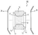
4 is a perspective view showing an insert type fastening member according to a first embodiment of the present invention.
5 is a longitudinal sectional view showing an insert type fastening member according to a first embodiment of the present invention.
6 is an exploded perspective view of the insert-type fastening member according to the first embodiment of the present invention.
7 is a perspective view illustrating a preferred insert type fastening member according to a first embodiment of the present invention.
8 is a perspective view showing a preferred insert type fastening member according to a first embodiment of the present invention.
9 is a perspective view showing a preferred insert type fastening member according to the first embodiment of the present invention.
10 is a perspective view showing a preferred insert type fastening member according to the first embodiment of the present invention.
11 is a longitudinal sectional view showing the insert type fastening member according to the first embodiment of the present invention in use.
12 is a vertical sectional view of an insert type fastening member according to second and fourth embodiments of the present invention.
13 is a perspective view showing an insert-type fastening member according to a third embodiment of the present invention.
14 is a partial longitudinal sectional view showing a preferred insert type fastening member according to a third embodiment of the present invention.
Hereinafter, embodiments according to the present invention will be described more specifically with reference to the accompanying drawings.
Prior to this, the following terms are defined in consideration of the functions of the present invention, and they are to be construed to mean concepts that are consistent with the technical idea of the present invention and interpretations that are commonly or commonly understood in the technical field of the present invention.
In the following description, well-known functions or constructions are not described in detail to avoid obscuring the subject matter of the present invention.
Hereinafter, the attached drawings are exaggerated or simplified in order to facilitate understanding and clarification of the structure and operation of the technology, and it is to be understood that each component does not exactly coincide with the actual size.
In addition, when a part includes an element, it does not exclude other elements unless specifically stated otherwise, but may include other elements.
≪ Embodiment 1 >
4 to 6, the insert-type fastening member according to the first embodiment of the present invention mainly includes a
The supporting
At least one
Here, the
The lower end of the
The
A plurality of
The tip portion of the
The burr formed by the
The
In addition, a plurality of
As shown in Figs. 8 and 9, when the
8 and 9, at the outer periphery between the
A
The
The
10, the receiving
7, in order to generate a frictional force against the rotation torque in the direction opposite to the direction in which the thread of the
That is, since the
The threaded
That is, the
The
That is, the
The inner circumferential surface of the hole of the
Here, the
The
Here, one
The
The
The inserting direction of the supporting
The reinforcing
The operation and operation of the insert-type fastening member according to the first embodiment of the present invention will now be described.
First, as shown in FIG. 11, when the
In addition, since the
The
As described above, the insert-type fastening member according to the first embodiment of the present invention can be used as an insert nut for preventing the fastening of a screw or detaching from an object to be fastened. In this case, the ease of use, And stability can be maximized.
≪ Embodiment 2 >
12, the insert-type fastening member according to the second embodiment of the present invention mainly includes a
Particularly, the O-
That is, when the O-
Here, among the constituent elements according to the second embodiment of the present invention, the same reference numerals are used for constituent elements having the same or similar operational effects as those of the first embodiment, and repetitive detailed description thereof will be omitted.
≪ Third Embodiment >
13 and 14, the insert-type fastening member according to the third embodiment of the present invention mainly includes a
The threaded
That is, in the insert type fastening member according to the third embodiment of the present invention, since the
Here, among constituent elements according to the third embodiment of the present invention, constituent elements having the same or similar operational effects as those of the above-described first embodiment use the same reference numerals, and repetitive and detailed explanations thereof will be omitted.
<Fourth Embodiment>
The insert-type fastening member according to the fourth embodiment of the present invention mainly comprises a
The
The insert-type fastening member according to the fourth embodiment of the present invention includes the O-
While the present invention has been particularly shown and described with reference to exemplary embodiments thereof, it is to be understood that the invention is not limited to the disclosed exemplary embodiments or constructions. Various changes and substitutions may be made without departing from the spirit and scope of the invention. It will be obvious to those skilled in the art that the present invention can be widely applied to other embodiments.
Therefore, it is to be understood that modifications and variations of the features of the present invention are intended to be included within the spirit and scope of the present invention.
110: Support portion 111: Friction Resistance Surface
120: body portion 121: key projection
121a: cutting edge 122: tooth
125: flange portion 126: curved tooth
127: Friction projection 128: Stopper groove
129:
130: screw hole 140: friction ring
141: frictional resistance surface 142:
143: convex portion 144: close face
150: liner 151: reinforcement part
160: O-ring 170: Screw
Claims (16)
At least one frictional resistance surface is formed on the outer periphery of the support portion to cause rotational friction resistance with the inner periphery of the friction ring hole,
An insert having a frictional resistance surface formed in a shape corresponding to a cross-sectional surface of the support portion to prevent rotation of the support portion and the body portion with respect to the friction ring by causing a rotation frictional resistance with an outer circumference of the support portion at an inner circumferential edge of the friction ring hole; Type fastening member.
Wherein the convex portion of the rubbing ring of the friction ring is bent obliquely in a direction opposite to the inserting direction of the supporting portion with respect to the mounting groove of the object to be fitted and the frictional force and the bearing force The insert-type fastening member is further provided with a contact surface for reinforcing the insert-type fastening member.
Wherein the convex portion of the rubbing ring of the friction ring is bent obliquely in a direction opposite to the inserting direction of the supporting portion with respect to the mounting groove of the object to be fitted and the frictional force and the bearing force Is further formed,
An insert-type fastening member integrally formed on the outer periphery of the liner to prevent the convex portion from being bent in the inserting direction of the support portion in an inclined manner in a direction opposite to the inserting direction of the support portion with respect to the mounting groove of the object to be fastened; .
The transverse cross-section of the body portion may be formed in a polygonal shape so as to generate a frictional force against rotation torque, or an insert type fastening member having a plurality of key projections formed in a shape of spline, serration, .
The insert-type fastening member has a pointed and sharp cutting edge formed at the tip of the key projection so as to form a burr while digging into the inner circumference of the mounting groove when press-fitted into the mounting groove of the object to be mounted.
An involute spline, a trochoid spline, and a helical spline are formed on the outer periphery of the body portion so as to generate a frictional force against rotation torque in a direction opposite to a direction in which the thread of the screw hole is wound. Type coupling member in which a plurality of curved teeth inclined obliquely in a shape of a helical shape are formed at regular intervals.
A flange portion integrally formed on an edge of a head portion of the body portion,
The cross-section of the flange portion is formed in a polygonal shape so as to generate a frictional force against rotation torque, or a plurality of teeth are formed at equal intervals at the rim,
A plurality of friction protrusions are formed on a surface of the flange portion facing the object to be fitted so as to generate frictional force against rotation torque,
A stopper groove is formed on the outer circumference between the flange portion and the body portion to prevent the outer edge of the mounting groove from being pushed in and slid off from the mounting groove of the mounting object when the mounting groove of the mounting object is press- Insert type fastening member.
At least one frictional resistance surface is formed on the outer periphery of the support portion to cause rotational friction resistance with the inner periphery of the friction ring hole,
An insert having a frictional resistance surface formed in a shape corresponding to a cross-sectional surface of the support portion to prevent rotation of the support portion and the body portion with respect to the friction ring by causing a rotation frictional resistance with an outer circumference of the support portion at an inner circumferential edge of the friction ring hole; Type fastening member.
Wherein a convex portion of the concavo-convex portion of the friction ring is bent in an inclined manner in a direction opposite to an insertion direction of the support portion with respect to the mounting groove of the object to be mounted, and a frictional force with an inner circumferential surface of the mounting- The insert-type fastening member is further provided with a contact surface for increasing the supporting force.
Wherein the convex portion of the rubbing ring of the friction ring is bent obliquely in a direction opposite to the inserting direction of the supporting portion with respect to the mounting groove of the object to be fitted and the frictional force and the bearing force Is further formed,
An insert-type fastening member integrally formed on the outer periphery of the liner to prevent the convex portion from being bent in the inserting direction of the support portion in an inclined manner in a direction opposite to the inserting direction of the support portion with respect to the mounting groove of the object to be fastened; .
The transverse cross-section of the body portion may be formed in a polygonal shape so as to generate a frictional force against rotation torque, or an insert type fastening member having a plurality of key projections formed in a shape of spline, serration, .
The insert-type fastening member has a pointed and sharp cutting edge formed at the tip of the key projection so as to form a burr while digging into the inner circumference of the mounting groove when press-fitted into the mounting groove of the object to be mounted.
A torsionally inclined shape in the shape of a spiral, an involute spline, a trochoid spline, or a helical shape so as to generate a frictional force against rotation torque is formed on the outer circumference of the body portion. An insert-type fastening member in which a plurality of curved teeth are formed at regular intervals.
A flange portion integrally formed on an edge of a head portion of the body portion,
The cross-section of the flange portion is formed in a polygonal shape so as to generate a frictional force against rotation torque, or a plurality of teeth are formed at equal intervals at the rim,
A plurality of friction protrusions are formed on a surface of the flange portion facing the object to be fitted so as to generate frictional force against rotation torque,
A stopper groove is formed on the outer circumference between the flange portion and the body portion to prevent the outer edge of the mounting groove from being pushed in and slid off from the mounting groove of the mounting object when the mounting groove of the mounting object is press- Insert type fastening member.
Priority Applications (1)
| Application Number | Priority Date | Filing Date | Title |
|---|---|---|---|
| KR1020150153556A KR20170051894A (en) | 2015-11-03 | 2015-11-03 | Insert type fastener member |
Applications Claiming Priority (1)
| Application Number | Priority Date | Filing Date | Title |
|---|---|---|---|
| KR1020150153556A KR20170051894A (en) | 2015-11-03 | 2015-11-03 | Insert type fastener member |
Publications (1)
| Publication Number | Publication Date |
|---|---|
| KR20170051894A true KR20170051894A (en) | 2017-05-12 |
Family
ID=58740175
Family Applications (1)
| Application Number | Title | Priority Date | Filing Date |
|---|---|---|---|
| KR1020150153556A KR20170051894A (en) | 2015-11-03 | 2015-11-03 | Insert type fastener member |
Country Status (1)
| Country | Link |
|---|---|
| KR (1) | KR20170051894A (en) |
Cited By (2)
| Publication number | Priority date | Publication date | Assignee | Title |
|---|---|---|---|---|
| KR20180119053A (en) * | 2017-04-24 | 2018-11-01 | 주식회사 에버다임 | Folding Boom Structure for Rock Drill |
| KR20240004069A (en) | 2022-07-04 | 2024-01-11 | 주식회사 일흥건영 | Insert type nut with idling prevention structure |
-
2015
- 2015-11-03 KR KR1020150153556A patent/KR20170051894A/en active IP Right Grant
Cited By (2)
| Publication number | Priority date | Publication date | Assignee | Title |
|---|---|---|---|---|
| KR20180119053A (en) * | 2017-04-24 | 2018-11-01 | 주식회사 에버다임 | Folding Boom Structure for Rock Drill |
| KR20240004069A (en) | 2022-07-04 | 2024-01-11 | 주식회사 일흥건영 | Insert type nut with idling prevention structure |
Similar Documents
| Publication | Publication Date | Title |
|---|---|---|
| EP3032119A1 (en) | Anti-loosening bolt assembly | |
| US20080014046A1 (en) | Retaining Element for Blocking Screw Elements | |
| JP5336644B1 (en) | Screw body reverse rotation prevention structure | |
| KR101861559B1 (en) | Washer for preventing untightening of nut or bolt | |
| TWI652413B (en) | Anti-reverse structure of threaded body | |
| JP2011252573A (en) | Locking washer and locking fastener using the same | |
| WO2020166462A1 (en) | Fastening member | |
| KR20170051894A (en) | Insert type fastener member | |
| US20130170924A1 (en) | Direct Tension Indicating Washer With Centering Elements | |
| EP3470695A1 (en) | Attachment device | |
| JP2019039555A (en) | Looseness prevention fastening structure | |
| CN211852449U (en) | Annular column check bolt fastener | |
| US20030049092A1 (en) | Securing nut and method for its fabrication | |
| US4889489A (en) | Device with spindle and grinding disk, particulary for dentists, and method for the manufacture thereof | |
| EP3832396A1 (en) | Device for attaching a timepiece display or trim element | |
| JP6039515B2 (en) | Screw body reverse rotation prevention structure | |
| KR101334520B1 (en) | Head detachable cutting tool, cutting head and holder | |
| JP2011117504A (en) | E-ext lock bolt | |
| JP5089327B2 (en) | Fastening member | |
| KR102098074B1 (en) | Bolt-nut assembly | |
| CN111140584A (en) | Annular column check bolt fastener | |
| JP2017025994A (en) | Fastener | |
| KR102194640B1 (en) | Bolt assembly reinforced to loose stopping | |
| JP2012017814A (en) | Loosening-prevention screwing structure | |
| JP6421307B2 (en) | Screw body reverse rotation prevention structure |
Legal Events
| Date | Code | Title | Description |
|---|---|---|---|
| A201 | Request for examination | ||
| E902 | Notification of reason for refusal | ||
| E701 | Decision to grant or registration of patent right |