KR20170051453A - Method for transmitting and receiving signals in a wireless communication system supporting carrier aggregation and apparatus therefor - Google Patents
Method for transmitting and receiving signals in a wireless communication system supporting carrier aggregation and apparatus therefor Download PDFInfo
- Publication number
- KR20170051453A KR20170051453A KR1020177007750A KR20177007750A KR20170051453A KR 20170051453 A KR20170051453 A KR 20170051453A KR 1020177007750 A KR1020177007750 A KR 1020177007750A KR 20177007750 A KR20177007750 A KR 20177007750A KR 20170051453 A KR20170051453 A KR 20170051453A
- Authority
- KR
- South Korea
- Prior art keywords
- downlink
- uplink
- cell
- specific time
- time interval
- Prior art date
Links
Images


Classifications
-
- H—ELECTRICITY
- H04—ELECTRIC COMMUNICATION TECHNIQUE
- H04L—TRANSMISSION OF DIGITAL INFORMATION, e.g. TELEGRAPHIC COMMUNICATION
- H04L5/00—Arrangements affording multiple use of the transmission path
- H04L5/003—Arrangements for allocating sub-channels of the transmission path
-
- H—ELECTRICITY
- H04—ELECTRIC COMMUNICATION TECHNIQUE
- H04W—WIRELESS COMMUNICATION NETWORKS
- H04W72/00—Local resource management
- H04W72/04—Wireless resource allocation
- H04W72/044—Wireless resource allocation based on the type of the allocated resource
- H04W72/0453—Resources in frequency domain, e.g. a carrier in FDMA
-
- H—ELECTRICITY
- H04—ELECTRIC COMMUNICATION TECHNIQUE
- H04L—TRANSMISSION OF DIGITAL INFORMATION, e.g. TELEGRAPHIC COMMUNICATION
- H04L5/00—Arrangements affording multiple use of the transmission path
- H04L5/0001—Arrangements for dividing the transmission path
- H04L5/0003—Two-dimensional division
- H04L5/0005—Time-frequency
- H04L5/0007—Time-frequency the frequencies being orthogonal, e.g. OFDM(A), DMT
- H04L5/001—Time-frequency the frequencies being orthogonal, e.g. OFDM(A), DMT the frequencies being arranged in component carriers
-
- H—ELECTRICITY
- H04—ELECTRIC COMMUNICATION TECHNIQUE
- H04L—TRANSMISSION OF DIGITAL INFORMATION, e.g. TELEGRAPHIC COMMUNICATION
- H04L1/00—Arrangements for detecting or preventing errors in the information received
- H04L1/12—Arrangements for detecting or preventing errors in the information received by using return channel
- H04L1/16—Arrangements for detecting or preventing errors in the information received by using return channel in which the return channel carries supervisory signals, e.g. repetition request signals
- H04L1/1607—Details of the supervisory signal
-
- H—ELECTRICITY
- H04—ELECTRIC COMMUNICATION TECHNIQUE
- H04L—TRANSMISSION OF DIGITAL INFORMATION, e.g. TELEGRAPHIC COMMUNICATION
- H04L1/00—Arrangements for detecting or preventing errors in the information received
- H04L1/12—Arrangements for detecting or preventing errors in the information received by using return channel
- H04L1/16—Arrangements for detecting or preventing errors in the information received by using return channel in which the return channel carries supervisory signals, e.g. repetition request signals
- H04L1/18—Automatic repetition systems, e.g. Van Duuren systems
- H04L1/1812—Hybrid protocols; Hybrid automatic repeat request [HARQ]
-
- H—ELECTRICITY
- H04—ELECTRIC COMMUNICATION TECHNIQUE
- H04L—TRANSMISSION OF DIGITAL INFORMATION, e.g. TELEGRAPHIC COMMUNICATION
- H04L1/00—Arrangements for detecting or preventing errors in the information received
- H04L1/12—Arrangements for detecting or preventing errors in the information received by using return channel
- H04L1/16—Arrangements for detecting or preventing errors in the information received by using return channel in which the return channel carries supervisory signals, e.g. repetition request signals
- H04L1/18—Automatic repetition systems, e.g. Van Duuren systems
- H04L1/1829—Arrangements specially adapted for the receiver end
- H04L1/1861—Physical mapping arrangements
-
- H—ELECTRICITY
- H04—ELECTRIC COMMUNICATION TECHNIQUE
- H04L—TRANSMISSION OF DIGITAL INFORMATION, e.g. TELEGRAPHIC COMMUNICATION
- H04L5/00—Arrangements affording multiple use of the transmission path
-
- H—ELECTRICITY
- H04—ELECTRIC COMMUNICATION TECHNIQUE
- H04L—TRANSMISSION OF DIGITAL INFORMATION, e.g. TELEGRAPHIC COMMUNICATION
- H04L5/00—Arrangements affording multiple use of the transmission path
- H04L5/003—Arrangements for allocating sub-channels of the transmission path
- H04L5/0053—Allocation of signaling, i.e. of overhead other than pilot signals
- H04L5/0055—Physical resource allocation for ACK/NACK
-
- H04W72/0406—
-
- H—ELECTRICITY
- H04—ELECTRIC COMMUNICATION TECHNIQUE
- H04W—WIRELESS COMMUNICATION NETWORKS
- H04W72/00—Local resource management
- H04W72/12—Wireless traffic scheduling
- H04W72/1263—Mapping of traffic onto schedule, e.g. scheduled allocation or multiplexing of flows
- H04W72/1268—Mapping of traffic onto schedule, e.g. scheduled allocation or multiplexing of flows of uplink data flows
-
- H—ELECTRICITY
- H04—ELECTRIC COMMUNICATION TECHNIQUE
- H04W—WIRELESS COMMUNICATION NETWORKS
- H04W72/00—Local resource management
- H04W72/12—Wireless traffic scheduling
- H04W72/1263—Mapping of traffic onto schedule, e.g. scheduled allocation or multiplexing of flows
- H04W72/1273—Mapping of traffic onto schedule, e.g. scheduled allocation or multiplexing of flows of downlink data flows
-
- H—ELECTRICITY
- H04—ELECTRIC COMMUNICATION TECHNIQUE
- H04W—WIRELESS COMMUNICATION NETWORKS
- H04W72/00—Local resource management
- H04W72/20—Control channels or signalling for resource management
-
- H—ELECTRICITY
- H04—ELECTRIC COMMUNICATION TECHNIQUE
- H04W—WIRELESS COMMUNICATION NETWORKS
- H04W72/00—Local resource management
- H04W72/04—Wireless resource allocation
- H04W72/044—Wireless resource allocation based on the type of the allocated resource
- H04W72/0446—Resources in time domain, e.g. slots or frames
Abstract
본 발명은 반송파 집성(Carrier Aggregation)을 지원하는 무선 통신 시스템에서, 단말의 다수 셀(cell)을 이용한 신호 송수신 방법 및 장치에 관한 것이다. 구체적으로, 서로 상이한 상향링크-하향링크 설정(Uplink-Downlink Configuration)에 따르는, 프라이머리 셀(Primary Cell, PCell) 및 세컨더리 셀(Secondary Cell, SCell)을 위한 전송 제어 정보를 수신하는 단계; 및 전송 제어 정보에 따라 특정 시간 구간 상에서 신호를 송수신하는 단계; 및 전송 제어 정보에서 특정 시간 구간상의 신호 송신을 지시하지 않는 경우, 미리 정의된 설정에 따른 신호 송수신 동작이 수행되는 단계를 포함한다.BACKGROUND OF THE INVENTION 1. Field of the Invention The present invention relates to a method and apparatus for transmitting and receiving signals using a plurality of cells of a mobile station in a wireless communication system supporting Carrier Aggregation. Specifically, receiving transmission control information for a primary cell (PCell) and a secondary cell (SCell) according to different uplink-downlink configurations; Transmitting and receiving a signal on a specific time interval according to transmission control information; And transmitting and receiving a signal according to a predefined setting when the transmission control information does not instruct signal transmission on a specific time interval.
Description
본 발명은 무선 통신 시스템에 관한 것으로서, 보다 상세하게는, 반송파 집성을 지원하는 무선 통신 시스템에서 신호 송수신 방법 및 이를 위한 장치에 관한 것이다.BACKGROUND OF THE
본 발명이 적용될 수 있는 무선 통신 시스템의 일례로서 3GPP LTE (3rd Generation Partnership Project Long Term Evolution, 이하 "LTE"라 함) 통신 시스템에 대해 개략적으로 설명한다.As an example of a wireless communication system to which the present invention can be applied, a 3GPP LTE (Third Generation Partnership Project) Long Term Evolution (LTE) communication system will be schematically described.
도 1은 무선 통신 시스템의 일례로서 E-UMTS 망구조를 개략적으로 도시한 도면이다. E-UMTS(Evolved Universal Mobile Telecommunications System) 시스템은 기존 UMTS(Universal Mobile Telecommunications System)에서 진화한 시스템으로서, 현재 3GPP에서 기초적인 표준화 작업을 진행하고 있다. 일반적으로 E-UMTS는 LTE(Long Term Evolution) 시스템이라고 할 수도 있다. UMTS 및 E-UMTS의 기술 규격(technical specification)의 상세한 내용은 각각 "3rd Generation Partnership Project; Technical Specification Group Radio Access Network"의 Release 7과 Release 8을 참조할 수 있다.1 is a diagram schematically showing an E-UMTS network structure as an example of a wireless communication system. The Evolved Universal Mobile Telecommunications System (E-UMTS) system evolved from the existing Universal Mobile Telecommunications System (UMTS), and is currently undergoing basic standardization work in 3GPP. In general, E-UMTS may be referred to as an LTE (Long Term Evolution) system. For details of the technical specifications of UMTS and E-UMTS, refer to
도 1을 참조하면, E-UMTS는 단말(User Equipment, UE)과 기지국(eNode B, eNB, 네트워크(E-UTRAN)의 종단에 위치하여 외부 네트워크와 연결되는 접속 게이트웨이(Access Gateway, AG)를 포함한다. 기지국은 브로드캐스트 서비스, 멀티캐스트 서비스 및/또는 유니캐스트 서비스를 위해 다중 데이터 스트림을 동시에 전송할 수 있다. Referring to FIG. 1, an E-UMTS includes an access gateway (AG), which is located at the end of a user equipment (UE) and a base station (eNode B, eNB and E-UTRAN) The base station may simultaneously transmit multiple data streams for the broadcast service, the multicast service, and / or the unicast service.
한 기지국에는 하나 이상의 셀이 존재한다. 셀은 1.25, 2.5, 5, 10, 15, 20Mhz 등의 대역폭 중 하나로 설정돼 여러 단말에게 하향 또는 상향 전송 서비스를 제공한다. 서로 다른 셀은 서로 다른 대역폭을 제공하도록 설정될 수 있다. 기지국은 다수의 단말에 대한 데이터 송수신을 제어한다. 하향 링크(Downlink, DL) 데이터에 대해 기지국은 하향 링크 스케줄링 정보를 전송하여 해당 단말에게 데이터가 전송될 시간/주파수 영역, 부호화, 데이터 크기, HARQ(Hybrid Automatic Repeat and reQuest) 관련 정보 등을 알려준다. 또한, 상향 링크(Uplink, UL) 데이터에 대해 기지국은 상향 링크 스케줄링 정보를 해당 단말에게 전송하여 해당 단말이 사용할 수 있는 시간/주파수 영역, 부호화, 데이터 크기, HARQ 관련 정보 등을 알려준다. 기지국간에는 사용자 트래픽 또는 제어 트래픽 전송을 위한 인터페이스가 사용될 수 있다. 핵심망(Core Network, CN)은 AG와 단말의 사용자 등록 등을 위한 네트워크 노드 등으로 구성될 수 있다. AG는 복수의 셀들로 구성되는 TA(Tracking Area) 단위로 단말의 이동성을 관리한다.One base station has more than one cell. The cell is set to one of the bandwidths of 1.25, 2.5, 5, 10, 15, 20Mhz and the like to provide downlink or uplink transmission service to a plurality of UEs. Different cells may be set up to provide different bandwidths. The base station controls data transmission / reception for a plurality of terminals. The base station transmits downlink scheduling information to the downlink (DL) data, and informs the corresponding terminal of the time / frequency region in which data is to be transmitted, coding, data size, and information related to HARQ (Hybrid Automatic Repeat and ReQuest). Also, the base station transmits uplink scheduling information to uplink (UL) data, and notifies the time / frequency region, coding, data size, and HARQ related information that the UE can use. An interface for transmitting user traffic or control traffic may be used between the base stations. The Core Network (CN) can be composed of AG and a network node for user registration of the terminal. The AG manages the mobility of the terminal in units of TA (Tracking Area) composed of a plurality of cells.
무선 통신 기술은 WCDMA를 기반으로 LTE까지 개발되어 왔지만, 사용자와 사업자의 요구와 기대는 지속적으로 증가하고 있다. 또한, 다른 무선 접속 기술이 계속 개발되고 있으므로 향후 경쟁력을 가지기 위해서는 새로운 기술 진화가 요구된다. 비트당 비용 감소, 서비스 가용성 증대, 융통성 있는 주파수 밴드의 사용, 단순구조와 개방형 인터페이스, 단말의 적절한 파워 소모 등이 요구된다.Wireless communication technologies have been developed to LTE based on WCDMA, but the demands and expectations of users and operators are continuously increasing. In addition, since other wireless access technologies are continuously being developed, new technology evolution is required to be competitive in the future. Cost reduction per bit, increased service availability, use of flexible frequency band, simple structure and open interface, and proper power consumption of terminal.
상술한 바와 같은 논의를 바탕으로 이하에서는 반송파 집성을 지원하는 무선 통신 시스템에서 신호 송수신 방법 및 이를 위한 장치를 제안하고자 한다.Based on the above discussion, a method of transmitting and receiving signals in a wireless communication system supporting carrier aggregation and an apparatus therefor are proposed.
본 발명에서 이루고자 하는 기술적 과제들은 상기 기술적 과제로 제한되지 않으며, 언급하지 않은 또 다른 기술적 과제들은 아래의 기재로부터 본 발명이 속하는 기술분야에서 통상의 지식을 가진 자에게 명확하게 이해될 수 있을 것이다.The technical problems to be solved by the present invention are not limited to the technical problems and other technical problems which are not mentioned can be understood by those skilled in the art from the following description.
상술한 문제점을 해결하기 위한 본 발명의 일 양상인, 반송파 집성(Carrier Aggregation)을 지원하는 무선 통신 시스템에서, 단말의 다수 셀(cell)을 이용한 신호 송수신 방법은, 서로 상이한 상향링크-하향링크 설정(Uplink-Downlink Configuration)에 따르는, 프라이머리 셀(Primary Cell, PCell) 및 세컨더리 셀(Secondary Cell, SCell)을 위한 전송 제어 정보를 수신하는 단계; 및 상기 전송 제어 정보에 따라 특정 시간 구간 상에서 신호를 송수신하는 단계; 및 상기 전송 제어 정보에서 상기 특정 시간 구간상의 신호 송신을 지시하지 않는 경우, 미리 정의된 설정에 따른 신호 송수신 동작이 수행되는 단계를 포함한다.In a wireless communication system supporting Carrier Aggregation, which is an aspect of the present invention for solving the above-mentioned problems, a method of transmitting / receiving a signal using a plurality of cells of a mobile station is different from that of the uplink- Receiving transmission control information for a primary cell (PCell) and a secondary cell (SCell) according to an uplink-downlink configuration; And transmitting and receiving signals on a specific time interval according to the transmission control information; And performing a signal transmission / reception operation according to a predefined setting when the transmission control information does not instruct signal transmission on the specific time interval.
나아가, 상기 특정 시간 구간 상에서 상기 프라이머리 셀이 상향링크 서브프레임이고 상기 세컨더리 셀이 하향링크 서브프레임인 경우, 상기 특정 시간 구간 상에서 상기 세컨더리 셀을 이용하여 하향링크 신호 수신 동작이 수행되는 것을 특징으로 할 수 있다. 더 나아가, 상기 하향링크 신호 수신 동작에 따른 HARQ-ACK 정보를, 셀프-스케쥴링 관련 하향링크 HARQ 타임라인을 이용하여 피드백하는 단계를 더 포함하는 것을 특징으로 할 수 있다. 바람직하게, 상기 셀프-스케줄링 관련 하향링크 HARQ 타임라인은, 상기 프라이머리 셀의 하향링크 서브프레임 집합과 상기 세컨더리 셀의 하향링크 서브프레임 집합을 모두 포함하도록 정의된 상향링크-하향링크 설정 관련 하향링크 HARQ 타임라인인 것을 특징으로 할 수 있다.Further, when the primary cell is the uplink sub-frame and the secondary cell is the downlink sub-frame in the specific time interval, the downlink signal reception operation is performed using the secondary cell on the specific time interval. can do. Further, the method may further include feeding back the HARQ-ACK information according to the downlink signal reception operation using a self-scheduling related downlink HARQ time line. Preferably, the self-scheduling-related downlink HARQ time line includes an uplink-downlink-related downlink HARQ (Time Division Multiple Access) related to a downlink subframe set of the primary cell and a set of downlink subframes of the secondary cell, And is a time line.
나아가, 상기 특정 시간 구간 상에서 상기 프라이머리 셀이 스페셜 서브프레임이고 상기 세컨더리 셀이 하향링크 서브프레임인 경우, 상기 특정 시간 구간의 적어도 일부에서 상기 세컨더리 셀을 이용하여 하향링크 신호 수신 동작이 수행되는 것을 특징으로 할 수 있다. 나아가, 상기 특정 시간 구간의 적어도 일부는, 상기 프라이머리 셀의 스페셜 서브프레임 상의 UpPTS와 대응하는 시간 구간을 포함하는 것을 특징으로 할 수 있다.Further, when the primary cell is the special sub-frame and the secondary cell is the downlink sub-frame in the specific time interval, the downlink signal receiving operation is performed using the secondary cell in at least a part of the specific time period . Further, at least a part of the specific time interval may include a time interval corresponding to the UpPTS on the special sub-frame of the primary cell.
나아가, 상기 특정 시간 구간 상에서 상기 프라이머리 셀이 하향링크 서브프레임이고 상기 세컨더리 셀이 상향링크 서브프레임인 경우, 상기 특정 시간 구간 상에서 상기 세컨더리 셀을 이용하여 미리 정의된 상향링크 신호를 송신하는 동작이 수행되는 것을 특징으로 할 수 있다. 더 나아가, 상기 미리 정의된 상향링크를 송신하는 동작은, 상기 세컨더리 셀의 상향링크 서브프레임 상에서의 상향링크 신호 전송을 위한 트리거링 정보를 수신한 경우에 수행되는 것을 특징으로 할 수 있다.Further, when the primary cell is a downlink subframe and the secondary cell is an uplink subframe on the specific time interval, an operation of transmitting a predefined uplink signal using the secondary cell on the specific time interval Is performed. Further, the operation of transmitting the predefined uplink may be performed when triggering information for uplink signal transmission on the uplink sub-frame of the secondary cell is received.
나아가, 상기 특정 시간 구간 상에서 상기 프라이머리 셀이 하향링크 서브프레임이고 상기 세컨더리 셀이 스페셜 서브프레임인 경우, 상기 특정 시간 구간의 적어도 일부에서 상기 세컨더리 셀을 이용하여 하향링크 신호 수신 동작이 수행되는 것을 특징으로 할 수 있다.Further, when the primary cell is a downlink sub-frame and the secondary cell is a special sub-frame on the specific time interval, a downlink signal reception operation is performed using the secondary cell in at least a part of the specific time period .
나아가, 특정 상향링크 서브프레임과 연동된 상향링크 신호/상향링크 채널 스케줄링 여부를 지시하는 정보를 수신하는 단계를 더 포함하는 것을 특징으로 할 수 있다.Further, the method may further include receiving information indicating whether uplink signal / uplink channel scheduling associated with a specific uplink subframe is interworked.
상술한 문제점을 해결하기 위한 본 발명의 다른 양상인, 반송파 집성(Carrier Aggregation)을 지원하는 무선 통신 시스템에서, 다수 셀(cell)을 이용한 신호 송수신을 수행하는 단말은 무선 주파수 유닛; 및 프로세서를 포함하며, 상기 프로세서는, 서로 상이한 상향링크-하향링크 설정(Uplink-Downlink Configuration)에 따르는, 프라이머리 셀(Primary Cell, PCell) 및 세컨더리 셀(Secondary Cell, SCell)을 위한 전송 제어 정보를 수신하고, 상기 전송 제어 정보에 따라 특정 시간 구간 상에서 신호를 송수신하도록 구성되며, 상기 전송 제어 정보에서 상기 특정 시간 구간상의 신호 송신을 지시하지 않는 경우, 미리 정의된 설정에 따른 신호 송수신 동작이 수행되도록 더 구성되는 것을 특징으로 한다.According to another aspect of the present invention for solving the above problems, in a wireless communication system supporting Carrier Aggregation, a terminal that performs signal transmission / reception using a plurality of cells includes a radio frequency unit; And a processor, wherein the processor is configured to transmit control information for a primary cell (PCell) and a secondary cell (SCell) according to different uplink-downlink configurations, And transmits and receives a signal on a specific time interval according to the transmission control information. When the transmission control information does not instruct signal transmission on the specific time interval, a signal transmission / reception operation according to a predefined setting is performed .
본 발명의 실시예에 따르면 무선 통신 시스템에서 신호 송수신이 효율적으로 수행될 수 있다.According to the embodiment of the present invention, signal transmission and reception in a wireless communication system can be efficiently performed.
본 발명에서 얻은 수 있는 효과는 이상에서 언급한 효과들로 제한되지 않으며, 언급하지 않은 또 다른 효과들은 아래의 기재로부터 본 발명이 속하는 기술분야에서 통상의 지식을 가진 자에게 명확하게 이해될 수 있을 것이다.The effects obtained by the present invention are not limited to the above-mentioned effects, and other effects not mentioned can be clearly understood by those skilled in the art from the following description will be.
본 발명에 관한 이해를 돕기 위해 상세한 설명의 일부로 포함되는, 첨부 도면은 본 발명에 대한 실시예를 제공하고, 상세한 설명과 함께 본 발명의 기술적 사상을 설명한다.
도 1은 무선 통신 시스템의 일례로서 E-UMTS 망구조를 개략적으로 예시한다.
도 2는 3GPP 무선 접속망 규격을 기반으로 한 단말과 E-UTRAN 사이의 무선 인터페이스 프로토콜(Radio Interface Protocol)의 제어평면(Control Plane) 및 사용자평면(User Plane) 구조를 예시한다.
도 3은 3GPP 시스템에 이용되는 물리 채널들 및 이들을 이용한 일반적인 신호 전송 방법을 예시한다.
도 4는 LTE 시스템에서 사용되는 무선 프레임의 구조를 예시한다.
도 5는 하향링크 슬롯에 대한 자원 그리드(resource grid)를 예시한다.
도 6은 LTE 시스템에서 사용되는 하향링크 무선 프레임의 구조를 예시한다.
도 7은 LTE 시스템에서 사용되는 상향링크 서브프레임의 구조를 예시한다.
도 8 및 도 9는 반송파 집성(Carrier Aggregation)을 설명하기 위한 참고도이다.
도 10 및 도 11은 본 발명에서 제안하는 방안들이 적용되는 시나리오들을 설명하기 위한 참고도이다.
도 12는 본 발명의 일 실시예에 적용될 수 있는 기지국 및 단말을 나타낸다.BRIEF DESCRIPTION OF THE DRAWINGS The accompanying drawings, which are included to provide a further understanding of the invention and are incorporated in and constitute a part of the specification, illustrate embodiments of the invention and, together with the description, serve to explain the principles of the invention.
1 schematically illustrates an E-UMTS network structure as an example of a wireless communication system.
2 illustrates a control plane and a user plane structure of a radio interface protocol between a UE and an E-UTRAN based on the 3GPP radio access network standard.
3 illustrates the physical channels used in the 3GPP system and a general signal transmission method using them.
4 illustrates a structure of a radio frame used in an LTE system.
FIG. 5 illustrates a resource grid for a downlink slot.
6 illustrates a structure of a downlink radio frame used in an LTE system.
7 illustrates a structure of an uplink subframe used in an LTE system.
8 and 9 are reference views for explaining carrier aggregation.
FIGS. 10 and 11 are reference views for explaining scenarios to which the present invention is applied.
12 shows a base station and a terminal that can be applied to an embodiment of the present invention.
이하의 기술은 CDMA(code division multiple access), FDMA(frequency division multiple access), TDMA(time division multiple access), OFDMA(orthogonal frequency division multiple access), SC-FDMA(single carrier frequency division multiple access) 등과 같은 다양한 무선 접속 시스템에 사용될 수 있다. CDMA는 UTRA(Universal Terrestrial Radio Access)나 CDMA2000과같은 무선 기술(radio technology)로 구현될 수 있다. TDMA는 GSM(Global System for Mobile communications)/GPRS(General Packet Radio Service)/EDGE(Enhanced Data Rates for GSM Evolution)와 같은 무선 기술로 구현될 수 있다. OFDMA는 IEEE 802.11 (Wi-Fi), IEEE 802.16 (WiMAX), IEEE 802-20, E-UTRA(Evolved UTRA) 등과 같은 무선 기술로 구현될 수 있다. UTRA는UMTS(Universal Mobile Telecommunications System)의 일부이다. 3GPP(3rd Generation Partnership Project) LTE(long term evolution)는 E-UTRA를 사용하는 E-UMTS(Evolved UMTS)의 일부로서 하향링크에서 OFDMA를 채용하고 상향링크에서 SC-FDMA를 채용한다. LTE-A(Advanced)는 3GPP LTE의 진화된 버전이다.The following description is to be understood as illustrative and non-limiting, such as code division multiple access (CDMA), frequency division multiple access (FDMA), time division multiple access (TDMA), orthogonal frequency division multiple access (OFDMA), single carrier frequency division multiple access And can be used in various wireless access systems. CDMA may be implemented in radio technology such as Universal Terrestrial Radio Access (UTRA) or CDMA2000. The TDMA may be implemented in a wireless technology such as Global System for Mobile communications (GSM) / General Packet Radio Service (GPRS) / Enhanced Data Rates for GSM Evolution (EDGE). OFDMA may be implemented in wireless technologies such as IEEE 802.11 (Wi-Fi), IEEE 802.16 (WiMAX), IEEE 802-20, and Evolved UTRA (E-UTRA). UTRA is part of the Universal Mobile Telecommunications System (UMTS). 3GPP (3rd Generation Partnership Project) LTE (Long Term Evolution) is part of E-UMTS (Evolved UMTS) using E-UTRA, adopts OFDMA in downlink and SC-FDMA in uplink. LTE-A (Advanced) is an evolved version of 3GPP LTE.
설명을 명확하게 하기 위해, 3GPP LTE/LTE-A를 위주로 기술하지만 본 발명의 기술적 사상이 이에 제한되는 것은 아니다. 또한, 이하의 설명에서 사용되는 특정(特定) 용어들은 본 발명의 이해를 돕기 위해서 제공된 것이며, 이러한 특정 용어의 사용은 본 발명의 기술적 사상을 벗어나지 않는 범위에서 다른 형태로 변경될 수 있다.For clarity of description, 3GPP LTE / LTE-A is mainly described, but the technical idea of the present invention is not limited thereto. In addition, the specific terms used in the following description are provided to aid understanding of the present invention, and the use of such specific terms may be changed into other forms without departing from the technical idea of the present invention.
도 2는 3GPP 무선 접속망 규격을 기반으로 한 단말과 E-UTRAN 사이의 무선 인터페이스 프로토콜(Radio Interface Protocol)의 제어평면(Control Plane) 및 사용자평면(User Plane) 구조를 나타내는 도면이다. 제어평면은 단말(User Equipment; UE)과 네트워크가 호를 관리하기 위해서 이용하는 제어 메시지들이 전송되는 통로를 의미한다. 사용자평면은 애플리케이션 계층에서 생성된 데이터, 예를 들어, 음성 데이터 또는 인터넷 패킷 데이터 등이 전송되는 통로를 의미한다.2 is a diagram showing a control plane and a user plane structure of a radio interface protocol between a UE and an E-UTRAN based on the 3GPP radio access network standard. The control plane refers to a path through which control messages used by a UE and a network are transferred. The user plane means a path through which data generated in the application layer, for example, voice data or Internet packet data, is transmitted.
제1계층인 물리계층은 물리채널(Physical Channel)을 이용하여 상위 계층에게 정보 전송 서비스(Information Transfer Service)를 제공한다. 물리계층은 상위에 있는 매체접속제어(Medium Access Control) 계층과는 전송채널(Trans안테나 포트 Channel)을 통해 연결되어 있다. 상기 전송채널을 통해 매체접속제어 계층과 물리계층 사이에 데이터가 이동한다. 송신측과 수신측의 물리계층 사이는 물리채널을 통해 데이터가 이동한다. 상기 물리채널은 시간과 주파수를 무선 자원으로 활용한다. 구체적으로, 물리채널은 하향 링크에서 OFDMA(Orthogonal Frequency Division Multiple Access) 방식으로 변조되고, 상향 링크에서 SC-FDMA(Single Carrier Frequency Division Multiple Access) 방식으로 변조된다.The physical layer as the first layer provides an information transfer service to an upper layer using a physical channel. The physical layer is connected to the upper Medium Access Control layer through a transmission channel (Trans antenna Port Channel). Data moves between the MAC layer and the physical layer over the transport channel. Data is transferred between the transmitting side and the receiving side physical layer through the physical channel. The physical channel utilizes time and frequency as radio resources. Specifically, the physical channel is modulated in an OFDMA (Orthogonal Frequency Division Multiple Access) scheme in a downlink, and is modulated in an SC-FDMA (Single Carrier Frequency Division Multiple Access) scheme in an uplink.
제2계층의 매체접속제어(Medium Access Control; MAC) 계층은 논리채널(Logical Channel)을 통해 상위계층인 무선링크제어(Radio Link Control; RLC) 계층에 서비스를 제공한다. 제2계층의 RLC 계층은 신뢰성 있는 데이터 전송을 지원한다. RLC 계층의 기능은 MAC 내부의 기능 블록으로 구현될 수도 있다. 제2계층의 PDCP(Packet Data Convergence Protocol) 계층은 대역폭이 좁은 무선 인터페이스에서 IPv4나 IPv6와 같은 IP 패킷을 효율적으로 전송하기 위해 불필요한 제어정보를 줄여주는 헤더 압축(Header Compression) 기능을 수행한다.The Medium Access Control (MAC) layer of the second layer provides a service to a radio link control (RLC) layer, which is an upper layer, through a logical channel. The RLC layer of the second layer supports reliable data transmission. The function of the RLC layer may be implemented as a functional block in the MAC. The Packet Data Convergence Protocol (PDCP) layer of the second layer performs a header compression function to reduce unnecessary control information in order to efficiently transmit IP packets such as IPv4 and IPv6 in a wireless interface with a narrow bandwidth.
제3계층의 최하부에 위치한 무선 자원제어(Radio Resource Control; RRC) 계층은 제어평면에서만 정의된다. RRC 계층은 무선베어러(Radio Bearer; RB)들의 설정(Configuration), 재설정(Re-configuration) 및 해제(Release)와 관련되어 논리채널, 전송채널 및 물리채널들의 제어를 담당한다. RB는 단말과 네트워크 간의 데이터 전달을 위해 제2계층에 의해 제공되는 서비스를 의미한다. 이를 위해, 단말과 네트워크의 RRC 계층은 서로 RRC 메시지를 교환한다. 단말과 네트워크의 RRC 계층 사이에 RRC 연결(RRC Connected)이 있을 경우, 단말은 RRC 연결 상태(Connected Mode)에 있게 되고, 그렇지 못할 경우 RRC 휴지 상태(Idle Mode)에 있게 된다. RRC 계층의 상위에 있는 NAS(Non-Access Stratum) 계층은 세션 관리(Session Management)와 이동성 관리(Mobility Management) 등의 기능을 수행한다.The Radio Resource Control (RRC) layer located at the bottom of the third layer is defined only in the control plane. The RRC layer is responsible for the control of logical channels, transport channels and physical channels in connection with the configuration, re-configuration and release of radio bearers (RBs). RB denotes a service provided by the second layer for data transmission between the UE and the network. To this end, the terminal and the RRC layer of the network exchange RRC messages with each other. If there is an RRC connection (RRC Connected) between the UE and the RRC layer of the network, the UE is in the RRC Connected Mode, otherwise it is in the RRC Idle Mode. The Non-Access Stratum (NAS) layer at the top of the RRC layer performs functions such as session management and mobility management.
기지국(eNB)을 구성하는 하나의 셀은 1.4, 3, 5, 10, 15, 20Mhz 등의 대역폭 중 하나로 설정되어 여러 단말에게 하향 또는 상향 전송 서비스를 제공한다. 서로 다른 셀은 서로 다른 대역폭을 제공하도록 설정될 수 있다.One cell constituting the base station eNB is set to one of the bandwidths of 1.4, 3, 5, 10, 15, and 20 MHz to provide downlink or uplink services to a plurality of UEs. Different cells may be set up to provide different bandwidths.
네트워크에서 단말로 데이터를 전송하는 하향 전송채널은 시스템 정보를 전송하는 BCH(Broadcast Channel), 페이징 메시지를 전송하는 PCH(Paging Channel), 사용자 트래픽이나 제어 메시지를 전송하는 하향 SCH(Shared Channel) 등이 있다. 하향 멀티캐스트 또는 방송 서비스의 트래픽 또는 제어 메시지의 경우 하향 SCH를 통해 전송될 수도 있고, 또는 별도의 하향 MCH(Multicast Channel)을 통해 전송될 수도 있다. 한편, 단말에서 네트워크로 데이터를 전송하는 상향 전송채널로는 초기 제어 메시지를 전송하는 RACH(Random Access Channel), 사용자 트래픽이나 제어 메시지를 전송하는 상향 SCH(Shared Channel)가 있다. 전송채널의 상위에 있으며, 전송채널에 매핑되는 논리채널(Logical Channel)로는 BCCH(Broadcast Control Channel), PCCH(Paging Control Channel), CCCH(Common Control Channel), MCCH(Multicast Control Channel), MTCH(Multicast Traffic Channel) 등이 있다.A downlink transmission channel for transmitting data from a network to a terminal includes a BCH (Broadcast Channel) for transmitting system information, a PCH (Paging Channel) for transmitting a paging message, a downlink SCH (Shared Channel) for transmitting user traffic or control messages, have. In case of a traffic or control message of a downlink multicast or broadcast service, it may be transmitted through a downlink SCH, or may be transmitted via a separate downlink multicast channel (MCH). Meanwhile, the uplink transmission channel for transmitting data from the UE to the network includes a random access channel (RACH) for transmitting an initial control message and an uplink SCH (shared channel) for transmitting user traffic or control messages. A logical channel mapped to a transport channel is a broadcast control channel (BCCH), a paging control channel (PCCH), a common control channel (CCCH), a multicast control channel (MCCH) Traffic Channel).
도 3은 3GPP LTE 시스템에 이용되는 물리 채널들 및 이들을 이용한 일반적인 신호 전송 방법을 설명하기 위한 도면이다. 3 is a view for explaining a physical channel used in a 3GPP LTE system and a general signal transmission method using the same.
전원이 꺼진 상태에서 다시 전원이 켜지거나, 새로이 셀에 진입한 사용자 기기는 단계 S301에서 기지국과 동기를 맞추는 등의 초기 셀 탐색(Initial cell search) 작업을 수행한다. 이를 위해 사용자 기기는 기지국으로부터 주동기 채널(Primary Synchronization Channel, P-SCH) 및 부동기 채널(Secondary Synchronization Channel, S-SCH)을 수신하여 기지국과 동기를 맞추고, 셀 ID 등의 정보를 획득한다. 그 후, 사용자 기기는 기지국으로부터 물리방송채널(Physical Broadcast Channel)를 수신하여 셀 내 방송 정보를 획득할 수 있다. 한편, 사용자 기기는 초기 셀 탐색 단계에서 하향링크 참조 신호(Downlink Reference Signal, DL RS)를 수신하여 하향링크 채널 상태를 확인할 수 있다.The user equipment that has been powered on again or has entered a new cell performs an initial cell search operation such as synchronizing with the base station in step S301. To this end, a user equipment receives a primary synchronization channel (P-SCH) and a secondary synchronization channel (S-SCH) from a base station, synchronizes with the base station, and acquires information such as a cell ID. Thereafter, the user equipment can receive the physical broadcast channel from the base station and obtain the in-cell broadcast information. Meanwhile, the UE may receive a downlink reference signal (DL RS) in an initial cell search step to check the downlink channel state.
초기 셀 탐색을 마친 사용자 기기는 단계 S302에서 물리 하향링크제어채널(Physical Downlink Control Channel, PDCCH) 및 물리하향링크제어채널 정보에 따른 물리하향링크공유 채널(Physical Downlink Control Channel, PDSCH)을 수신하여 좀더 구체적인 시스템 정보를 획득할 수 있다.Upon completion of the initial cell search, the user equipment receives a Physical Downlink Control Channel (PDCCH) and a Physical Downlink Control Channel (PDSCH) according to physical downlink control channel information in step S302, Specific system information can be obtained.
이후, 사용자 기기는 기지국에 접속을 완료하기 위해 이후 단계 S303 내지 단계 S306과 같은 임의 접속 과정(Random Access Procedure)을 수행할 수 있다. 이를 위해 사용자 기기는 물리임의접속채널(Physical Random Access Channel, PRACH)을 통해 프리앰블(preamble)을 전송하고(S303), 물리하향링크제어채널 및 이에 대응하는 물리하향링크공유 채널을 통해 프리앰블에 대한 응답 메시지를 수신할 수 있다(S304). 경쟁 기반 임의 접속의 경우 추가적인 물리임의접속채널의 전송(S305) 및 물리하향링크제어채널 및 이에 대응하는 물리하향링크공유 채널 수신(S306)과 같은 충돌해결절차(Contention Resolution Procedure)를 수행할 수 있다.Thereafter, the user equipment can perform a random access procedure such as steps S303 to S306 to complete the connection to the base station. To this end, the user equipment transmits a preamble through a physical random access channel (PRACH) (S303), and transmits a response to the preamble through the physical downlink control channel and the corresponding physical downlink shared channel Message (S304). In the case of a contention-based random access, a contention resolution procedure such as transmission of an additional physical random access channel (S305) and physical downlink control channel and corresponding physical downlink shared channel reception (S306) may be performed .
상술한 바와 같은 절차를 수행한 사용자 기기는 이후 일반적인 상/하향링크 신호 전송 절차로서 물리하향링크제어채널/물리하향링크공유채널 수신(S307) 및 물리상향링크공유채널(Physical Uplink Shared Channel, PUSCH)/물리상향링크제어채널(Physical Uplink Control Channel, PUCCH) 전송(S308)을 수행할 수 있다. 사용자 기기가 기지국으로 전송하는 제어 정보를 통칭하여 상향링크 제어 정보(Uplink Control Information, UCI)라고 지칭한다. UCI는 HARQ ACK/NACK(Hybrid Automatic Repeat and reQuest Acknowledgement/Negative-ACK), SR(Scheduling Request), CSI(Channel State Information) 등을 포함한다. 본 명세서에서, HARQ ACK/NACK은 간단히 HARQ-ACK 혹은 ACK/NACK(A/N)으로 지칭된다. HARQ-ACK은 포지티브 ACK(간단히, ACK), 네거티브 ACK(NACK), DTX 및 NACK/DTX 중 적어도 하나를 포함한다. CSI는 CQI(Channel Quality Indicator), PMI(Precoding Matrix Indicator), RI(Rank Indication) 등을 포함한다. UCI는 일반적으로 PUCCH를 통해 전송되지만, 제어 정보와 트래픽 데이터가 동시에 전송되어야 할 경우 PUSCH를 통해 전송될 수 있다. 또한, 네트워크의 요청/지시에 의해 PUSCH를 통해 UCI를 비주기적으로 전송할 수 있다. The user equipment having performed the procedure described above transmits a physical downlink control channel / physical downlink shared channel reception (S307) and a physical uplink shared channel (PUSCH) as general uplink / downlink signal transmission procedures, / Physical Uplink Control Channel (PUCCH) transmission (S308). The control information transmitted from the user equipment to the base station is collectively referred to as Uplink Control Information (UCI). The UCI includes HARQ ACK / NACK (Hybrid Automatic Repeat and Request Acknowledgment / Negative ACK), SR (Scheduling Request), CSI (Channel State Information) In this specification, HARQ ACK / NACK is simply referred to as HARQ-ACK or ACK / NACK (A / N). The HARQ-ACK includes at least one of positive ACK (simply ACK), negative ACK (NACK), DTX and NACK / DTX. The CSI includes a Channel Quality Indicator (CQI), a Precoding Matrix Indicator (PMI), a Rank Indication (RI), and the like. The UCI is generally transmitted through the PUCCH, but may be transmitted via the PUSCH when the control information and the traffic data are to be simultaneously transmitted. In addition, UCI can be transmitted non-periodically through the PUSCH according to the request / instruction of the network.
도 4는 LTE 시스템에서 사용되는 무선 프레임의 구조를 예시하는 도면이다.4 is a diagram illustrating a structure of a radio frame used in an LTE system.
도 4를 참조하면, 셀룰라 OFDM 무선 패킷 통신 시스템에서, 상향링크/하향링크 데이터 패킷 전송은 서브프레임(subframe) 단위로 이루어지며, 한 서브프레임은 다수의 OFDM 심볼을 포함하는 일정 시간 구간으로 정의된다. 3GPP LTE 표준에서는 FDD(Frequency Division Duplex)에 적용 가능한 타입 1 무선 프레임(radio frame) 구조와 TDD(Time Division Duplex)에 적용 가능한 타입 2의 무선 프레임 구조를 지원한다. Referring to FIG. 4, in a cellular OFDM wireless packet communication system, uplink / downlink data packet transmission is performed on a subframe basis, and one subframe is defined as a predetermined time interval including a plurality of OFDM symbols . The 3GPP LTE standard supports a
도4의 (a)는 타입 1 무선 프레임의 구조를 예시한다. 하향링크 무선 프레임(radio frame)은 10개의 서브프레임(subframe)으로 구성되고, 하나의 서브프레임은 시간 영역(time domain)에서 2개의 슬롯(slot)으로 구성된다. 하나의 서브프레임이 전송되는 데 걸리는 시간을 TTI(transmission time interval)라 한다. 예를 들어 하나의 서브프레임의 길이는 1ms이고, 하나의 슬롯의 길이는 0.5ms 일 수 있다. 하나의 슬롯은 시간 영역에서 복수의 OFDM 심볼을 포함하고, 주파수 영역에서 다수의 자원블록(Resource Block; RB)을 포함한다. 3GPP LTE 시스템에서는 하향링크에서 OFDMA 를 사용하므로, OFDM 심볼이 하나의 심볼 구간을 나타낸다. OFDM 심볼은 또한 SC-FDMA 심볼 또는 심볼 구간으로 칭하여질 수도 있다. 자원 할당 단위로서의 자원 블록(RB)은 하나의 슬롯에서 복수개의 연속적인 부반송파(subcarrier)를 포함할 수 있다. 4 (a) illustrates the structure of a
하나의 슬롯에 포함되는 OFDM 심볼의 수는 CP(Cyclic Prefix)의 구성(configuration)에 따라 달라질 수 있다. CP에는 확장된 CP(extended CP)와 표준 CP(normal CP)가 있다. 예를 들어, OFDM 심볼이 표준 CP에 의해 구성된 경우, 하나의 슬롯에 포함되는 OFDM 심볼의 수는 7개일 수 있다. OFDM 심볼이 확장된 CP에 의해 구성된 경우, 한 OFDM 심볼의 길이가 늘어나므로, 한 슬롯에 포함되는 OFDM 심볼의 수는 표준 CP인 경우보다 적다. 확장된 CP의 경우에, 예를 들어, 하나의 슬롯에 포함되는 OFDM 심볼의 수는 6개일 수 있다. 사용자 기기가 빠른 속도로 이동하는 등의 경우와 같이 채널상태가 불안정한 경우, 심볼간 간섭을 더욱 줄이기 위해 확장된 CP가 사용될 수 있다.The number of OFDM symbols included in one slot may vary according to the configuration of a CP (Cyclic Prefix). CP has an extended CP and a normal CP. For example, when an OFDM symbol is configured by a standard CP, the number of OFDM symbols included in one slot may be seven. When the OFDM symbol is configured by an extended CP, the length of one OFDM symbol is increased, so that the number of OFDM symbols included in one slot is smaller than that in the standard CP. In the case of the extended CP, for example, the number of OFDM symbols included in one slot may be six. If the channel condition is unstable, such as when the user equipment is moving at a high speed, an extended CP may be used to further reduce intersymbol interference.
표준 CP가 사용되는 경우 하나의 슬롯은 7개의 OFDM 심볼을 포함하므로, 하나의 서브프레임은 14개의 OFDM 심볼을 포함한다. 이때, 각 서브프레임의 처음 최대 3 개의 OFDM 심볼은 PDCCH(physical downlink control channel)에 할당되고, 나머지 OFDM 심볼은 PDSCH(physical downlink shared channel)에 할당될 수 있다.One slot includes 7 OFDM symbols when a standard CP is used, so one subframe includes 14 OFDM symbols. At this time, the first three OFDM symbols at the beginning of each subframe may be allocated to a physical downlink control channel (PDCCH), and the remaining OFDM symbols may be allocated to a physical downlink shared channel (PDSCH).
도4의 (b)는 타입 2 무선 프레임의 구조를 예시한다. 타입 2 무선 프레임은 2개의하프 프레임(half frame)으로 구성되며, 각 하프 프레임은 2개의 슬롯을 포함하는 4개의 일반 서브프레임과 DwPTS(Downlink Pilot Time Slot), 보호구간(Guard Period, GP) 및UpPTS(Uplink Pilot Time Slot)을 포함하는 특별 서브프레임(special subframe)으로 구성된다. 4 (b) illustrates the structure of a
상기 특별 서브프레임에서, DwPTS는 사용자 기기에서의 초기 셀 탐색, 동기화 또는 채널 추정에 사용된다. UpPTS는 기지국에서의 채널 추정과 사용자 기기의 상향링크 전송 동기를 맞추는 데 사용된다. 즉, DwPTS는 하향링크 전송으로, UpPTS는 상향링크 전송으로 사용되며, 특히 UpPTS는 PRACH 프리앰블이나 SRS 전송의 용도로 활용된다. 또한, 보호구간은 상향링크와 하향링크 사이에 하향링크 신호의 다중경로 지연으로 인해 상향링크에서 생기는 간섭을 제거하기 위한 구간이다.In this special subframe, the DwPTS is used for initial cell search, synchronization, or channel estimation in the user equipment. UpPTS is used to synchronize the channel estimation at the base station and the uplink transmission synchronization of the user equipment. That is, the DwPTS is used for downlink transmission and the UpPTS is used for uplink transmission. In particular, UpPTS is used for PRACH preamble or SRS transmission. Also, the guard interval is a period for eliminating the interference occurring in the uplink due to the multi-path delay of the downlink signal between the uplink and the downlink.
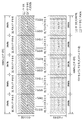
상기 특별 서브프레임에 관하여 현재 3GPP 표준 문서에서는 아래 표 1과 같이 설정을 정의하고 있다. 표 1에서 ![]()
![]()

한편, 타입 2 무선 프레임의 구조, 즉 TDD 시스템에서 상향링크/하향링크 서브프레임 설정(UL/DL configuration)은 아래의 표 2와 같다.Meanwhile, Table 2 below shows the structure of the

상기 표 2에서 D는 하향링크 서브프레임, U는 상향링크 서브프레임을 지시하며, S는 상기 특별 서브프레임을 의미한다. 또한, 상기 표 2는 각각의 시스템에서 상향링크/하향링크 서브프레임 설정에서 하향링크-상향링크 스위칭 주기 역시 나타나있다.In Table 2, D denotes a downlink subframe, U denotes an uplink subframe, and S denotes the special subframe. Table 2 also shows the downlink-uplink switching period in the uplink / downlink subframe setup in each system.
상술한 무선 프레임의 구조는 예시에 불과하고, 무선 프레임에 포함되는 서브프레임의 수 또는 서브프레임에 포함되는 슬롯의 수, 슬롯에 포함되는 심볼의 수는 다양하게 변경될 수 있다.The structure of the radio frame is merely an example, and the number of subframes included in a radio frame, the number of slots included in a subframe, and the number of symbols included in a slot can be changed variously.
도 5는 하향링크 슬롯에 대한 자원 그리드(resource grid)를 예시한다.FIG. 5 illustrates a resource grid for a downlink slot.
도 5를 참조하면, 하향링크 슬롯은 시간 영역에서 ![]()
![]()
![]()
![]()
![]()
![]()
![]()
![]()
![]()
![]()
자원그리드 상의 각 요소를 자원요소(Resource Element; RE)라 하고, 하나의 자원 요소는 하나의 OFDM 심볼 인덱스 및 하나의 부반송파 인덱스로 지시된다. 하나의 RB는 ![]()
![]()
![]()
![]()
![]()
![]()
도 6은 하향링크 서브프레임의 구조를 예시한다.6 illustrates the structure of a downlink sub-frame.
도 6을 참조하면, 서브프레임의 첫 번째 슬롯에서 앞부분에 위치한 최대 3(4)개의 OFDM 심볼은 제어 채널이 할당되는 제어 영역에 대응한다. 남은 OFDM 심볼은 PDSCH(Physical Downlink Shared Channel)가 할당되는 데이터 영역에 해당한다. LTE에서 사용되는 하향링크 제어 채널의 예는 PCFICH(Physical Control Format Indicator Channel), PDCCH(Physical Downlink Control Channel), PHICH(Physical hybrid ARQ indicator Channel) 등을 포함한다. PCFICH는 서브프레임의 첫 번째 OFDM 심볼에서 전송되고 서브프레임 내에서 제어 채널의 전송에 사용되는 OFDM 심볼의 개수에 관한 정보를 나른다. PHICH는 상향링크 전송에 대한 응답으로 HARQ ACK/NACK(Hybrid Automatic Repeat request acknowledgment/negative-acknowledgment) 신호를 나른다.Referring to FIG. 6, a maximum of 3 (4) OFDM symbols located at the beginning of a first slot of a subframe corresponds to a control region to which a control channel is allocated. The remaining OFDM symbol corresponds to a data area to which PDSCH (Physical Downlink Shared Channel) is allocated. Examples of downlink control channels used in LTE include Physical Control Format Indicator Channel (PCFICH), Physical Downlink Control Channel (PDCCH), Physical Hybrid ARQ Indicator Channel (PHICH), and the like. The PCFICH carries information about the number of OFDM symbols transmitted in the first OFDM symbol of the subframe and used for transmission of the control channel in the subframe. The PHICH carries a HARQ ACK / NACK (Hybrid Automatic Repeat request acknowledgment / negative-acknowledgment) signal in response to the uplink transmission.
PDCCH를 통해 전송되는 제어 정보를 DCI(Downlink Control Information)라고 지칭한다. DCI는 사용자 기기 또는 사용자 기기 그룹을 위한 자원 할당 정보 및 다른 제어 정보를 포함한다. 예를 들어, DCI는 상향/하향링크 스케줄링 정보, 상향링크 전송(Tx) 파워 제어 명령 등을 포함한다.The control information transmitted through the PDCCH is referred to as DCI (Downlink Control Information). The DCI includes resource allocation information and other control information for the user equipment or user equipment group. For example, the DCI includes uplink / downlink scheduling information, uplink transmission (Tx) power control commands, and the like.
PDCCH는 하향링크 공유 채널(downlink shared channel, DL-SCH)의 전송 포맷 및 자원 할당 정보, 상향링크 공유 채널(uplink shared channel,UL-SCH)의 전송 포맷 및 자원 할당 정보, 페이징 채널(paging channel, PCH) 상의 페이징 정보, DL-SCH 상의 시스템 정보, PDSCH 상에서 전송되는 랜덤 접속 응답과 같은 상위-계층 제어 메시지의 자원 할당 정보, 사용자 기기 그룹 내의 개별 사용자 기기들에 대한 Tx 파워 제어 명령 세트, Tx 파워 제어 명령, VoIP(Voice over IP)의 활성화 지시 정보 등을 나른다. 복수의 PDCCH가 제어 영역 내에서 전송될 수 있다. 사용자 기기는 복수의 PDCCH를 모니터링 할 수 있다. PDCCH는 하나 또는 복수의 연속된 제어 채널 요소(control channel element, CCE)들의 집합(aggregation) 상에서 전송된다. CCE는 PDCCH에 무선 채널 상태에 기초한 코딩 레이트를 제공하는데 사용되는 논리적 할당 유닛이다. CCE는 복수의 자원 요소 그룹(resource element group, REG)에 대응한다. PDCCH의 포맷 및 PDCCH 비트의 개수는 CCE의 개수에 따라 결정된다. 기지국은 사용자 기기에게 전송될 DCI에 따라 PDCCH 포맷을 결정하고, 제어 정보에 CRC(cyclic redundancy check)를 부가한다. CRC는 PDCCH의 소유자 또는 사용 목적에 따라 식별자(예, RNTI(radio network temporary identifier))로 마스킹 된다. 예를 들어, PDCCH가 특정 사용자 기기를 위한 것일 경우, 해당 사용자 기기의 식별자(예, cell-RNTI (C-RNTI))가 CRC에 마스킹 될 수 있다. PDCCH가 페이징 메시지를 위한 것일 경우, 페이징식별자(예, paging-RNTI (P-RNTI))가 CRC에 마스킹 될 수 있다. PDCCH가 시스템 정보(보다 구체적으로, 시스템 정보 블록(system Information block, SIC))를 위한 것일 경우, SI-RNTI(system Information RNTI)가 CRC에 마스킹 될 수 있다. PDCCH가 랜덤 접속 응답을 위한 것일 경우, RA-RNTI(random access-RNTI)가 CRC에 마스킹 될 수 있다.PDCCH includes a transmission format and resource allocation information of a downlink shared channel (DL-SCH), a transmission format and resource allocation information of an uplink shared channel (UL-SCH), a paging channel, Layer control message such as random access response transmitted on the PDSCH, Tx power control instruction set for individual user equipments in the user equipment group, Tx power < RTI ID = 0.0 > Control instructions, and information for activating Voice over IP (VoIP). A plurality of PDCCHs may be transmitted within the control domain. The user equipment can monitor a plurality of PDCCHs. The PDCCH is transmitted on an aggregation of one or a plurality of consecutive control channel elements (CCEs). The CCE is a logical allocation unit used to provide the PDCCH with a coding rate based on radio channel conditions. The CCE corresponds to a plurality of resource element groups (REG). The format of the PDCCH and the number of PDCCH bits are determined according to the number of CCEs. The base station determines the PDCCH format according to the DCI to be transmitted to the user equipment, and adds a CRC (cyclic redundancy check) to the control information. The CRC is masked with an identifier (e.g., radio network temporary identifier (RNTI)) according to the owner of the PDCCH or the purpose of use. For example, if the PDCCH is for a particular user equipment, the identifier of the user equipment (e.g., cell-RNTI (C-RNTI)) may be masked to the CRC. If the PDCCH is for a paging message, the paging identifier (e.g., paging-RNTI (P-RNTI)) may be masked to the CRC. If the PDCCH is for system information (more specifically, a system information block (SIC)), the system information RNTI (SI-RNTI) may be masked to the CRC. If the PDCCH is for a random access response, a random access-RNTI (RA-RNTI) may be masked in the CRC.
도 7은 LTE에서 사용되는 상향링크 서브프레임의 구조를 예시한다.7 illustrates a structure of an uplink subframe used in LTE.
도 7을 참조하면, 상향링크 서브프레임은 복수(예, 2개)의 슬롯을 포함한다. 슬롯은 CP 길이에 따라 서로 다른 수의 SC-FDMA 심볼을 포함할 수 있다. 상향링크 서브프레임은 주파수 영역에서 데이터 영역과 제어 영역으로 구분된다. 데이터영역은 PUSCH를 포함하고 음성등의 데이터 신호를 전송하는데 사용된다. 제어영역은 PUCCH를 포함하고 상향링크 제어정보(Uplink Control Information, UCI)를 전송하는데 사용된다. PUCCH는 주파수축에서 데이터 영역의 양끝 부분에 위치한 RB 쌍(RB pair)을 포함하며 슬롯을 경계로 호핑한다.Referring to FIG. 7, the uplink subframe includes a plurality of (e.g., two) slots. The slot may include a different number of SC-FDMA symbols depending on the CP length. The UL subframe is divided into a data region and a control region in the frequency domain. The data area includes a PUSCH and is used to transmit a data signal such as voice. The control region includes a PUCCH and is used to transmit uplink control information (UCI). The PUCCH includes an RB pair (RB pair) located at both ends of the data area on the frequency axis and hopping the slot to the boundary.
PUCCH는 다음의 제어 정보를 전송하는데 사용될 수 있다.The PUCCH may be used to transmit the following control information.
- SR(Scheduling Request): 상향링크 UL-SCH 자원을 요청하는데 사용되는 정보이다. OOK(On-Off Keying) 방식을 이용하여 전송된다.- SR (Scheduling Request): Information used for requesting uplink UL-SCH resources. OOK (On-Off Keying) method.
- HARQ ACK/NACK:PDSCH 상의 하향링크 데이터 패킷에 대한 응답 신호이다. 하향링크 데이터 패킷이 성공적으로 수신되었는지 여부를 나타낸다. 단일 하향링크 코드워드에 대한 응답으로 ACK/NACK 1비트가 전송되고, 두 개의 하향링크 코드워드에 대한 응답으로 ACK/NACK 2비트가 전송된다.- HARQ ACK / NACK: This is a response signal to the downlink data packet on the PDSCH. Indicates whether the downlink data packet has been successfully received. In response to a single downlink codeword, one bit of ACK / NACK is transmitted and two bits of ACK / NACK are transmitted in response to two downlink codewords.
- CSI(Channel State Information): 하향링크 채널에 대한 피드백 정보이다. CSI는 CQI(Channel Quality Indicator)를 포함하고, MIMO(Multiple Input Multiple Output) 관련 피드백 정보는 RI(Rank Indicator), PMI(Precoding Matrix Indicator), PTI(Precoding 타입 Indicator) 등을 포함한다. 서브프레임 당 20비트가 사용된다.- CSI (Channel State Information): feedback information on the downlink channel. The CSI includes a CQI (Channel Quality Indicator), and feedback information related to Multiple Input Multiple Output (MIMO) includes a Rank Indicator (RI), a Precoding Matrix Indicator (PMI), and a Precoding Type Indicator (PTI). 20 bits per subframe are used.
사용자 기기가 서브프레임에서 전송할 수 있는 제어 정보(UCI)의 양은 제어 정보 전송에 가용한 SC-FDMA의 개수에 의존한다. 제어 정보 전송에 가용한 SC-FDMA는 서브프레임에서 참조 신호 전송을 위한 SC-FDMA 심볼을 제외하고 남은 SC-FDMA 심볼을 의미하고, SRS(Sounding Reference Signal)가 설정된 서브프레임의 경우 서브프레임의 마지막 SC-FDMA 심볼도 제외된다. 참조 신호는 PUCCH의 코히어런트 검출에 사용된다. The amount of control information (UCI) that the user equipment can transmit in the subframe depends on the number of SC-FDMAs available for control information transmission. The SC-FDMA available for transmission of control information means the remaining SC-FDMA symbol excluding the SC-FDMA symbol for reference signal transmission in the subframe. In the case of the subframe in which the SRS (Sounding Reference Signal) is set, SC-FDMA symbols are excluded. The reference signal is used for coherent detection of the PUCCH.
도 8는 캐리어 병합(Carrier Aggregation, CA) 통신 시스템을 예시한다.Figure 8 illustrates a Carrier Aggregation (CA) communication system.
도 8을 참조하면, 복수의 상/하향링크 컴포넌트 반송파(Component Carrier, CC)들을 모아서 더 넓은 상/하향링크 대역폭을 지원할 수 있다. 용어 “컴포넌트 반송파(CC)”는 등가의 다른 용어(예, 캐리어, 셀 등)로 대체될 수 있다. 각각의 CC들은 주파수 영역에서 서로 인접하거나 비-인접할 수 있다. 각 컴포넌트 반송파의 대역폭은 독립적으로 정해질 수 있다. UL CC의 개수와 DL CC의 개수가 다른 비대칭 반송파 집성도 가능하다. 한편, 제어 정보는 특정 CC를 통해서만 송수신 되도록 설정될 수 있다. 이러한 특정 CC를 프라이머리 CC(또는 앵커 CC)로 지칭하고, 나머지 CC를 세컨더리 CC로 지칭할 수 있다.Referring to FIG. 8, a plurality of uplink / downlink component carriers (CCs) may be aggregated to support a wider uplink / downlink bandwidth. The term " component carrier (CC) " may be replaced by another equivalent term (e.g., carrier, cell, etc.). Each CC may be adjacent or non-adjacent to one another in the frequency domain. The bandwidth of each component carrier can be determined independently. Asymmetric carrier aggregation with different numbers of UL CCs and DL CCs is also possible. On the other hand, the control information can be set to be transmitted and received only through a specific CC. This particular CC may be referred to as a primary CC (or anchor CC), and the remaining CC as a secondary CC.
크로스-캐리어 스케줄링 (또는 크로스-CC 스케줄링)이 적용될 경우, 하향링크 할당을 위한 PDCCH는 DL CC#0으로 전송되고, 해당 PDSCH는 DL CC#2로 전송될 수 있다. 크로스-CC 스케줄링을 위해, 캐리어 지시 필드(carrier indicator field, CIF)의 도입이 고려될 수 있다. PDCCH 내에서 CIF의 존재 여부는 상위 계층 시그널링(예, RRC 시그널링)에 의해 반-정적 및 단말-특정(또는 단말 그룹-특정) 방식으로 설정될 수 있다. PDCCH 전송의 베이스 라인을 요약하면 다음과 같다.When the cross-carrier scheduling (or cross-CC scheduling) is applied, the PDCCH for downlink allocation is transmitted to the
■ CIF 디스에이블드(disabled): DL CC 상의 PDCCH는 동일한 DL CC 상의 PDSCH 자원을 할당하거나 하나의 링크된 UL CC 상의 PUSCH 자원을 할당CIF disabled: The PDCCH on the DL CC allocates a PDSCH resource on the same DL CC or a PUSCH resource on one linked UL CC
● No CIF● No CIF
● LTE PDCCH 구조(동일한 부호화, 동일한 CCE-기반 자원 맵핑) 및 DCI 포맷과 동일● Same as LTE PDCCH structure (same encoding, same CCE-based resource mapping) and DCI format
■ CIF 이네이블드(enabled): DL CC 상의 PDCCH는 CIF를 이용하여 복수의 병합된 DL/UL CC 중에서 특정 DL/UL CC 상의 PDSCH 또는 PUSCH 자원을 할당 가능CIF enabled: PDCCH on DL CC can allocate PDSCH or PUSCH resources on specific DL / UL CC among multiple merged DL / UL CC using CIF
● CIF를 가지는 확장된 LTE DCI 포맷● Extended LTE DCI format with CIF
- CIF (설정될 경우)는 고정된 x-비트 필드(예, x=3)- CIF (if set) is a fixed x-bit field (eg x = 3)
- CIF (설정될 경우) 위치는 DCI 포맷 사이즈에 관계 없이 고정됨- CIF (if set) position is fixed regardless of DCI format size
● LTE PDCCH 구조를 재사용(동일한 부호화, 동일한 CCE-기반 자원 맵핑)● Reuse LTE PDCCH structure (same encoding, same CCE-based resource mapping)
CIF가 존재할 경우, 기지국은 단말 측의 BD 복잡도를 낮추기 위해 PDCCH 모니터링 DL CC 세트를 할당할 수 있다. PDCCH 모니터링 DL CC 세트는 병합된 전체 DL CC의 일부로서 하나 이상의 DL CC를 포함하고 단말은 해당 DL CC 상에서만 PDCCH의 검출/복호화를 수행한다. 즉, 기지국이 단말에게 PDSCH/PUSCH를 스케줄링 할 경우, PDCCH는 PDCCH 모니터링 DL CC 세트를 통해서만 전송된다. PDCCH 모니터링 DL CC 세트는 단말-특정(UE-specific), 단말-그룹-특정 또는 셀-특정(cell-specific) 방식으로 설정될 수 있다. 용어 “PDCCH 모니터링 DL CC”는 모니터링 캐리어, 모니터링 셀 등과 같은 등가의 용어로 대체될 수 있다. 또한, 단말을 위해 병합된 CC는 서빙 CC, 서빙 캐리어, 서빙 셀 등과 같은 등가의 용어로 대체될 수 있다.If CIF is present, the base station may allocate a PDCCH monitoring DL CC set to lower BD complexity on the UE side. The PDCCH monitoring DL CC set includes one or more DL CCs as part of the merged whole DL CCs, and the UE performs detection / decoding of the PDCCH only on the corresponding DL CCs. That is, when the BS schedules the PDSCH / PUSCH to the UE, the PDCCH is transmitted only through the PDCCH monitoring DL CC set. PDCCH Monitoring The DL CC set may be set in a UE-specific, UE-group-specific or cell-specific manner. The term " PDCCH monitoring DL CC " may be replaced by equivalent terms such as monitoring carrier, monitoring cell, and the like. Also, the CC merged for the UE may be replaced with equivalent terms such as serving CC, serving carrier, serving cell, and so on.
도 9는 복수의 캐리어가 병합된 경우의 스케줄링을 예시한다. 3개의 DL CC가 병합되었다고 가정한다. DL CC A가 PDCCH 모니터링 DL CC로 설정되었다고 가정한다. DL CC A~C는 서빙 CC, 서빙 캐리어, 서빙 셀 등으로 지칭될 수 있다. CIF가 디스에이블 된 경우, 각각의 DL CC는 LTE PDCCH 설정에 따라 CIF 없이 자신의 PDSCH를 스케줄링 하는 PDCCH만을 전송할 수 있다. 반면, 단말-특정 (또는 단말-그룹-특정 또는 셀-특정) 상위 계층 시그널링에 의해 CIF가 이네이블 된 경우, DL CC A(모니터링 DL CC)는 CIF를 이용하여 DL CC A의 PDSCH를 스케줄링 하는 PDCCH뿐만 아니라 다른 CC의 PDSCH를 스케줄링 하는 PDCCH도 전송할 수 있다. 이 경우, PDCCH 모니터링 DL CC로 설정되지 않은 DL CC B/C에서는 PDCCH가 전송되지 않는다. 따라서, DL CC A(모니터링 DL CC)는 DL CC A와 관련된 PDCCH 검색 영역, DL CC B와 관련된 PDCCH 검색 영역 및 DL CC C와 관련된 PDCCH 검색 영역을 모두 포함해야 한다. 본 명세서에서, PDCCH 검색 영역은 캐리어 별로 정의된다고 가정한다.FIG. 9 illustrates scheduling when a plurality of carriers are merged. It is assumed that three DL CCs are merged. It is assumed that DL CC A is set to PDCCH monitoring DL CC. DL CC A-C may be referred to as serving CC, serving carrier, serving cell, and the like. When the CIF is disabled, each DL CC may transmit only a PDCCH that schedules its PDSCH without CIF according to the LTE PDCCH setting. On the other hand, when the CIF is enabled by the UE-specific (or UE-group-specific or cell-specific) upper layer signaling, the DL CC A (monitoring DL CC) schedules the PDSCH of the DL CC A using the CIF PDCCH for scheduling the PDSCH of another CC as well as the PDCCH. In this case, the PDCCH is not transmitted in the DL CC B / C not set to the PDCCH monitoring DL CC. Therefore, the DL CC A (monitoring DL CC) must include both the PDCCH search area associated with DL CC A, the PDCCH search area associated with DL CC B, and the PDCCH search area associated with DL CC C. In this specification, it is assumed that the PDCCH search area is defined for each carrier.
상술한 바와 같이, LTE-A는 크로스-CC 스케줄링을 위하여 PDCCH 내에서 CIF 사용을 고려하고 있다. CIF의 사용 여부 (즉, 크로스-CC 스케줄링 모드 또는 논-크로스-CC 스케줄링 모드의 지원) 및 모드간 전환은 RRC 시그널링을 통해 반-정적/단말-특정하게 설정될 수 있고, 해당 RRC 시그널링 과정을 거친 후 단말은 자신에게 스케줄링 될 PDCCH 내에 CIF가 사용되는지 여부를 인식할 수 있다. As described above, LTE-A is considering using CIF within the PDCCH for cross -CC scheduling. The switching between modes and the use of CIFs (i.e., support of cross-CC scheduling mode or non-cross-CC scheduling mode) can be set semi-static / UE-specific via RRC signaling and the corresponding RRC signaling process After roughing, the terminal can recognize whether CIF is used in the PDCCH to be scheduled for itself.
이하에서는, 본 발명에 따라 반송파 집성 기법 (Carrier Aggregation, CA)이 적용된 셀(혹은 컴포넌트 캐리어)들 간에, 서로 다른 통신 방향으로 인한 간섭이 존재할 때, 특정 셀 상의 무선 자원을 효율적으로 사용하는 방법에 대하여 설명한다.Hereinafter, a method for efficiently using radio resources on a specific cell when interference due to different communication directions exists between cells (or component carriers) to which a Carrier Aggregation (CA) is applied according to the present invention .
이하에서는 설명의 편의를 위해 3GPP LTE 시스템을 기반으로 본 발명을 설명한다. 하지만, 본 발명이 적용되는 시스템의 범위는 3GPP LTE 시스템 외에 다른 시스템으로도 확장 가능하다. Hereinafter, the present invention will be described based on 3GPP LTE system for convenience of explanation. However, the scope of the system to which the present invention is applied can be extended to other systems besides the 3GPP LTE system.
또한, 이하에서는 본 발명에 대한 설명의 편의를 위해서, INTRA-BAND CA 기법(이하, “INTRA_BD_CA”)이 적용되고, 해당 셀들 간에 상이한 상향링크-하향링크 설정(UL-DL CONFIGURATION)이 설정된 상황(이하, “INTRA_BD_CA W/ DIFF_CONFIG”)을 가정한다. 참고로, 본 발명의 실시예들은 상술한 상황(즉, “INTRA_BD_CA W/ DIFF_CONFIG”) 뿐만 아니라, CA 기법이 적용된 셀들 간에 서로 다른 통신 방향으로 인한 간섭이 존재하거나 발생되는 모든 상황들에서 확장 적용이 가능하다.Hereinafter, for the convenience of description of the present invention, a case where an INTRA-BAND CA scheme (hereinafter referred to as " INTRA_BD_CA ") is applied and a different UL-DL configuration is set between the cells Hereinafter, " INTRA_BD_CA W / DIFF_CONFIG "). For reference, embodiments of the present invention are not limited to the situations described above (i.e., " INTRA_BD_CA W / DIFF_CONFIG "), as well as in all situations where interferences due to different communication directions between CA- It is possible.
또한, 본 발명의 실시예들은 CA 기법이 적용된 셀들 (e.g., INTER-BAND CA 기법 (이하, “INTER_BD_CA”) 상의 특정 시점에서 동시 송/수신이 가능하지 않은 단말들, 혹은 CA 기법이 적용된 셀들 (즉, INTER_BD_CA) 상의 특정 시점에서 동시 송/수신은 가능하지만 INTRA_BD_CA로 인한 자가 간섭(SELF-INTERFERENCE) 문제로 실제 동시 송/수신 동작이 불가능한 단말들에게도 확장 적용이 가능하다. The embodiments of the present invention can also be applied to terminals that are not capable of simultaneous transmission / reception at a specific time point on a cell to which a CA scheme is applied (e.g., INTER-BAND CA scheme (hereinafter referred to as "INTER_BD_CA" In other words, simultaneous transmission / reception is possible at a specific point on the INTER_BD_CA, but it is possible to extend to the terminals that can not perform the actual simultaneous transmission / reception operation due to the self interference (SELF-INTERFERENCE) due to INTRA_BD_CA.
나아가, 'INTRA_BD_CA W/ DIFF_CONFIG'의 환경 하에서, 상향링크/하향링크 통신은 아래 표 3및 표 4에 따라 (재)이용하여 수행되도록 설정될 수 가 있다. 이는, 단말이 CA 기법이 적용된 셀들 (예, INTER_BD_CA) 상의 특정 시점에서 동시 송/수신이 가능한지의 여부에 상관없이, INTRA_BD_CA W/ DIFF_CONFIG 환경 하에서는, 단말이 항상 CA 기법이 적용된 셀들 상의 특정 시점에서 동시 송/수신은 불가능하다고 가정하는 것으로 해석될 수 도 있다. Further, under the environment of 'INTRA_BD_CA W / DIFF_CONFIG', the uplink / downlink communication can be set to be performed by (re) using Table 3 and Table 4 below. This is because, under the INTRA_BD_CA W / DIFF_CONFIG environment, regardless of whether the terminal is able to simultaneously transmit / receive data at a specific time on the CA-applied cells (e.g., INTER_BD_CA) It can be interpreted as assuming that transmission / reception is impossible.
여기서, 아래 표 3 및 표 4에 따르면, PCell의 자원 용도와 불일치되는 SCell의 자원 상에서는 실제 통신이 수행되지 않거나혹은 실제 통신 수행이 기대되지 않는 것으로 판단(즉, PCell의 자원 용도 및 사용에 우선권이 존재함)될 수 가 있다. 또한, INTRA_BD_CA W/ DIFF_CONFIG 환경 하에서 이를 적용할 경우, PCell과 SCell 간의 서로 다른 통신 방향으로 인한 간섭을 회피할 수 가 있다. 하지만, INTRA_BD_CA W/ DIFF_CONFIG 환경 하에서 표 3 및 표 4의 규칙을 (재)이용할 경우, PCell의 자원 용도 및 사용에 우선권이 존재함으로써, SCell의 (하향링크/상향링크) 자원을 트래픽 부하 상태 변화에 따라 효율적으로 이용하지 못하는 문제가 발생하게 된다.Here, according to Table 3 and Table 4 below, it is determined that actual communication is not performed or real communication is not expected to be performed on the resources of the SCell that are inconsistent with the resource usage of the PCell (that is, Can exist). In addition, when applied in the INTRA_BD_CA W / DIFF_CONFIG environment, it is possible to avoid interference due to different communication directions between PCell and SCell. However, when (re) using the rules of Table 3 and Table 4 under the INTRA_BD_CA W / DIFF_CONFIG environment, there is a priority in the use and use of PCell, so that SCell's (downlink / uplink) Therefore, there arises a problem that it can not be utilized efficiently.
이하, 반송파 집성(CA) 기법이 적용된 셀들 상의 특정 시점에서, 동시 송수신이 불가능한 단말들의 통신 동작에 대한 규칙/설정을 표 3 및 표 4로 나타낸다. 표 3에 대한 보다 자세한 설명은 LTE/LTE-A 관련 3GPP TS 36.211 Section 4.2 “Frame structure type 2” 를 참조할 수 있으며, 표 4에 대한 보다 자세한 설명은 및 3GPP TS 36.213 Section 7.2.3 “Channel Quality Indicator (CQI) definition”를 참조할 수 있다.Table 3 and Table 4 show the rules / setting for the communication operation of the terminals that can not simultaneously transmit / receive at a specific time on the cells to which the carrier aggregation (CA) technique is applied. A more detailed description of Table 3 can be found in 3GPP TS 36.211 Section 4.2 "

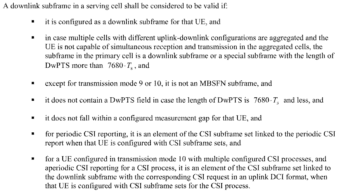
전술한 내용을 바탕으로, 본 발명에서 CA 기법이 적용된 셀(혹은 컴포넌트 캐리어)들 간에, 서로 다른 통신 방향으로 인한 간섭이 존재 (예, INTRA_BD_CA W/ DIFF_CONFIG) 할 때, 특정 셀 상의 무선 자원을 효율적으로 사용하는 방법을 설명한다. 예를 들어, 표 3 및 표 4의 규칙에 기반하여 이하 본 발명의 적어도 일부(즉, 일부 혹은 모든) 실시예를 적용함으로써, 상술한 표 3 혹은 표 4의 적용으로 인해 발생되는 문제(예, SCell의 (하향링크/상향링크) 자원을 트래픽 부하 상태 변화에 따라 효율적으로 이용하지 못하는 문제)를 해결할 수 가 있다. Based on the above description, it can be seen that when there is interference (e.g., INTRA_BD_CAW / DIFF_CONFIG) due to different communication directions between cells (or component carriers) to which the CA scheme is applied in the present invention, Will be described. For example, by applying at least some (i. E., Some or all) embodiments of the present invention based on the rules of Tables 3 and 4 below, problems arising from the application of Table 3 or Table 4, The problem of not being able to efficiently utilize SCell's (downlink / uplink) resources according to a change in traffic load state) can be solved.
도 10는 본 발명의 실시예(예, 제 1 방안 내지 제 3 방안)이 적용될 수 있는 경우를 나타낸다. 여기서, PCell(예, Macro eNB)은 상향링크-하향링크 설정#1으로 설정되고, SCell(예, Pico eNB)은 상향링크-하향링크 설정 #3으로 설정되었다고 가정한다. 또한, 도 10는 IDEAL BACKHAUL (혹은 NON-IDEAL BACKHAUL)로 연결되어 있는, Macro eNB(즉, PCell)와 Pico eNB (즉, SCell)가 CA 기법 혹은 DUAL CONNECTIVITY 기법 (예를 들어, INTRA_BD_CA W/ DIFF_CONFIG)으로 설정된 상황을 가정하였다.Fig. 10 shows a case where an embodiment of the present invention (for example, a first scheme to a third scheme) can be applied. Here, it is assumed that PCell (e.g., Macro eNB) is set to uplink-
제 1 방안First Plan
도 10을 참조하여 본 발명을 설명하면, 특정 SF#N 시점에서 PCell(예, Cell#A)은 UL SF이고 SCell(예, Cell#B)은 DL SF인 경우(예, SF#(n+7), SF#(n+8)), PCell UL SF 상에서 실제로 (사전에 정의된) 상향링크 시그널 전송(예, PUSCH, PUCCH (A/N, CSI), SR, SRS 등)이 설정/지시되지 않는 경우, 단말은 동일 시점(즉, SF#(n+7), SF#(n+8))의 SCell DL SF 상에서 (E)PDCCH 블라인드 디코딩 (그리고/혹은 PDSCH 수신 동작)을 수행하도록 설정될 수 가 있다. 이러한 방식은, SF#N에서 PCell이 Cell#A에서 Cell#B로 변경되거나, 혹은 SCell이 Cell#B에서 Cell#A로 변경된 것으로 해석될 수 도 있다. 10, the PCell (e.g., Cell # A) is UL SF and the SCell (e.g., Cell # B) is DL SF (e.g., SF # (E.g., PUSCH, PUCCH (A / N, CSI), SR, SRS, etc.) on the PCell UL SF are set / , The UE is set to perform PDCCH blind decoding (and / or PDSCH receiving operation) on the SCell DL SF of the same time (i.e., SF # (n + 7), SF # (n + 8) Can be. This method may be interpreted that PCell is changed from Cell # A to Cell # B in SF # N, or SCell is changed from Cell # B to Cell # A.
또 다른 일례로, 제 1 방안이 적용되는 PCell UL SF (혹은 SCell DL SF)에 대한 위치들에 대한 정보(예, 비트맵)가 사전에 정의된 시그널 (예, 물리 계층 시그널 혹은 상위 계층 시그널)을 통해서 단말에게 전달될 수 도 있다. In another example, information (e.g., a bitmap) about locations for a PCell UL SF (or SCell DL SF) to which the first scheme is applied may be a predefined signal (e.g., a physical layer signal or a higher layer signal) Lt; / RTI > to the terminal.
여기서, 제 1 방안이 적용되는 위치들에 대한 정보를 전달하여 제 1 방안이 적용되는 PCell UL SF (혹은 SCell DL SF) 위치를 한정함으로써, 단말이 PCell UL SF 상에서의 (사전에 정의된) 상향링크 시그널 전송 (예, PUSCH, A-CSI, A-SRS 등) 관련 제어 정보를 성공적으로 수신하지 못함으로써 발생되는, 기지국과 단말 간에 실제 통신이 수행되는 자원 (예, PCell UL SF 혹은 SCell DL SF) 가정에 대한 불일치 문제를 완화 시킬 수 있다. Here, by transmitting the information about the locations to which the first scheme is applied and limiting the location of the PCell UL SF (or SCell DL SF) to which the first scheme is applied, (Eg, PCell UL SF or SCell DL SF) generated by a failure to successfully receive control information associated with link signaling (eg, PUSCH, A-CSI, A-SRS, etc.) ) It can alleviate the problem of discrepancies in assumptions.
제 2 방안Second Plan
도 10를 참조하여 본 발명을 설명하면, 특정 SF#N 시점에서 PCell(즉, Cell#A)은 스페셜 서브프레임(SPECIAL SF)이고 SCell (즉, Cell#B)은 DL SF인 경우(예, SF #(n+6)), PCell UpPTS 상에서 실제 (사전에 정의된) 상향링크 시그널 전송(예, SRS 등)이 설정/지시되지 않는 경우, 단말에 대하여 동일 시점(즉, SF #(n+6))의 SCell DL SF 영역의 적어도 일부(즉, 일부 혹은 전체) 상에서 (E)PDCCH 블라인드 디코딩 (그리고/혹은 PDSCH 수신 동작)을 수행하도록 설정될 수 가 있다. 10, PCell (i.e., Cell # A) is a special subframe SPECIAL SF and SCell (i.e., Cell # B) is a DL SF (e.g., SF # (n + 6)), if the actual (predefined) uplink signal transmission (e.g., SRS) is not set / indicated on the PCell UpPTS, (And / or PDSCH receive operation) on at least a portion (i.e., part or all) of the SCell DL SF region of the PDCCH 6).
여기서, 일부 SCell DL SF 영역은 PCell DwPTS에 해당되는 SCell DL SF 영역, 즉, SCell DL SF을 PCell과 동일한 설정의 SPECIAL SF으로 가정하고 SCell DwPTS 영역에서만 (E)PDCCH/PDSCH 수신이 가능한 것으로 정의될 수 있다. 혹은 PCell DwPTS/GP에 해당되는 SCell DL SF 영역 (즉, SCell DL SF을 PCell과 동일한 설정의 SPECIAL SF으로 가정하고 SCell DwPTS/GP 영역에서만 (E)PDCCH/PDSCH 수신이 가능한 것으로 정의될 수 가 있다. 또한, 본 발명에서, SF#N에서 PCell이 Cell#A에서 Cell#B로 변경된 것 (혹은 SCell이 Cell#B에서 Cell#A로 변경된 것)으로 해석될 수 도 있다. Herein, it is assumed that some SCELL DL SF regions are assumed to be the SCELL DL SF regions corresponding to the PCell DwPTS, that is, the SCELL DL SFs are SPECIAL SFs having the same setting as PCell, and the PDCCH / PDSCH reception is possible only in the SCell DwPTS region . Alternatively, the SCell DL SF field corresponding to the PCell DwPTS / GP (i.e., the SCell DL SF can be defined as being a SPECIAL SF with the same setting as the PCell, and PDCCH / PDSCH reception is possible only in the SCell DwPTS / GP domain . In addition, in the present invention, it can be interpreted that PCell is changed from Cell # A to Cell # B (or SCell is changed from Cell # B to Cell # A) in SF # N.
또 다른 예로, 제 2 방안이 적용되는 PCell SPECIAL SF (혹은 SCell DL SF)에 대한 위치들에 대한 정보 (예, 비트맵)가 사전에 정의된 시그널 (예, 물리 계층 시그널 혹은 상위 계층 시그널)을 통해서 단말에게 전달될 수 도 있다. 여기서, 제 2 방안이 적용되는 위치들에 대한 정보를 전달하여 제 2 방안이 적용되는 PCell SPECIAL SF (혹은 SCell DL SF) 위치를 한정함으로써, 단말이 PCell UpPTS 상에서의 (사전에 정의된) 상향링크 시그널 전송 (예, A-SRS 등) 관련 제어 정보를 성공적으로 수신하지 못함으로써 발생되는, 기지국과 단말 간에 실제 통신이 수행되는 자원 (예, PCell SPECIAL SF 혹은 SCell DL SF) 가정에 대한 불일치 문제를 완화 시킬 수 있다. As another example, information about positions (e.g., bitmap) for PCell SPECIAL SF (or SCell DL SF) to which the second scheme is applied may be a predefined signal (e.g., physical layer signal or upper layer signal) It may be delivered to the terminal. Here, by transmitting the information about the positions to which the second scheme is applied and limiting the PCell SPECIAL SF (or SCell DL SF) position to which the second scheme is applied, the UE can transmit the uplink (predefined) (Eg, PCell SPECIAL SF or SCell DL SF) assuming that the actual communication between the base station and the terminal is caused by not successfully receiving the control information related to the signal transmission (eg, A-SRS) Can be mitigated.
제 3 방안Third Plan
도 10를 참조하여 본 발명을 설명하면, 특정 SF#N 시점에서 PCell (즉, Cell#A)은 DL SF이고 SCell (즉, Cell#B)은 UL SF인 경우(예, SF#(n+4)), 사전에 정의된 지시자 수신 혹은 사전에 정의된 규칙 적용을 통해서, 단말로 하여금, SCell UL SF이 (사전에 정의된) 상향링크 시그널 전송 (예, PUSCH, SRS 등) 용도로 이용되도록 설정될 수 가 있다. 10, when PCell (i.e., Cell # A) is a DL SF and SCell (i.e., Cell # B) is an UL SF (e.g., SF # (Eg, PUSCH, SRS, etc.) for the SCell UL SF (predefined) through the use of predefined indicators or predefined rules Can be set.
여기서, 해당 지시자는 SCell UL SF 상에서 (사전에 정의된) 상향링크 시그널 전송을 트리거링 혹은 스케줄링하는 UL GRANT 정보, 혹은 해당 용도로 새롭게 정의된 지시자 (예, 물리 계층 지시자(PDCCH) 혹은 상위 계층 지시자 (RRC)) 등으로 정의될 수 가 있다. Here, the indicator may include UL GRANT information for triggering or scheduling the uplink signal transmission (predefined) on the SCell UL SF, or UL GRANT information for triggering or scheduling the transmission of a newly defined indicator (e.g., a physical layer indicator (PDCCH) RRC)) and the like.
상향링크 시그널 전송을 트리거링 혹은 스케줄링하는 UL GRANT 정보에 대한 예로, SCell UL HARG 타임라인에 따라 SCell의 SF#(N-4) 시점(예, 도 10에서 SF#(n)) (즉, SELF SCHEDULING CASE) (혹은 PCell의 DL SF#(N-4) (예, 도 10에서 SF#(n)) 즉, CROSS SCHEDULING CASE)에서, SCell UL SF#N 상에서의 PUSCH 전송 관련 UL GRANT 정보를 수신하였다면, 단말은 SCell UL SF#N에서 PUSCH 전송을 수행하고, PCell DL SF#N에서 (E)PDCCH/PDSCH 수신 동작을 수행하지 않는다. 이러한 방안은, SF#N에서 PCell이 Cell#A에서 Cell#B로 변경된 것 (혹은 SCell이 Cell#B에서 Cell#A로 변경된 것)으로 해석될 수 도 있다. An example of UL GRANT information for triggering or scheduling uplink signaling is an SF # (N-4) viewpoint (e.g., SF # (n) in FIG. 10) of the SCell according to the SCell UL HARG timeline (i.e., SELF SCHEDULING (UL SF # N in FIG. 10), i.e., a CROSS SCHEDULING CASE) of the SCELL UL SF # N , The UE performs the PUSCH transmission in the SCell UL SF # N and does not perform the (E) PDCCH / PDSCH reception in the PCell DL SF # N. This approach may be interpreted as a change in PCell from Cell # A to Cell # B (or SCell changed from Cell # B to Cell # A) in SF # N.
또한, 제 3 방안이 적용되는 PCell DL SF (혹은 SCell UL SF)에 대한 위치들에 대한 정보(예, 비트맵)가 사전에 정의된 시그널 (예, 물리 계층 시그널 혹은 상위 계층 시그널)을 통해서 단말에게 전달될 수 도 있다. 여기서, 제 3 방안이 적용되는 위치들에 대한 정보를 전달하여 제 3 방안이 적용되는 PCell DL SF (혹은 SCell UL SF) 위치를 한정함으로써, 단말이 SCell UL SF 상에서의 (사전에 정의된) 상향링크 시그널 전송 (예, PUSCH, A-CSI, A-SRS 등) 관련 제어 정보를 성공적으로 수신하지 못함으로써 발생되는, 기지국과 단말 간에 실제 통신이 수행되는 자원 (예, PCell DL SF 혹은 SCell UL SF) 가정에 대한 불일치 문제를 완화 시킬 수 있다.Further, information on positions (e.g., bit map) of the PCell DL SF (or SCell UL SF) to which the third scheme is applied is transmitted through a predefined signal (e.g., a physical layer signal or an upper layer signal) . Here, by transmitting the information on the locations to which the third scheme is applied and limiting the location of the PCell DL SF (or SCell UL SF) to which the third scheme is applied, (Eg, PCell DL SF or SCell UL SF) generated by a failure to successfully receive control information related to link signaling (eg, PUSCH, A-CSI, A-SRS, etc.) ) It can alleviate the problem of discrepancies in assumptions.
제 4 방안The fourth plan
도 11은 본 발명의 제 4 방안이 적용될 수 있는 경우를 설명하기 위한 참고도이다. 도 11에서, PCell은 상향링크-하향링크 설정#3(즉, 'DSUUUDDDDD')으로 설정되고, SCell은 상향링크-하향링크 설정#1(즉, 'DSUUDDSUUD')로 설정되었다고 가정하였다. 또한, 도 11는 IDEAL BACKHAUL (혹은 NON-IDEAL BACKHAUL)로 연결되어 있는, Macro eNB(즉, PCell)와 Pico eNB (즉, SCell)가 CA 기법 혹은 DUAL CONNECTIVITY 기법 (예를 들어, INTRA_BD_CA W/ DIFF_CONFIG)으로 설정된 상황을 가정하였다. 11 is a reference diagram for explaining a case where the fourth method of the present invention can be applied. 11, it is assumed that PCell is set to uplink-downlink setting # 3 (i.e., 'DSUUUDDDDD') and SCell is set to uplink-downlink setting # 1 (i.e., 'DSUUDDSUUD'). 11 shows a case where a Macro eNB (i.e., PCell) and a Pico eNB (i.e., SCell) connected to IDEAL BACKHAUL (or NON-IDEAL BACKHAUL) ), Respectively.
도 11을 참조하여 본 발명을 설명하면, 특정 SF#N 시점(예, SF #(n+6))에서 PCell(즉, Cell#A)은 DL SF이고 SCell(즉, Cell#B)은 스페셜 서브프레임(SPECIAL SF)인 경우, 사전에 정의된 규칙에 따라, SCell SPECIAL SF 영역의 적어도 일부(즉, 일부 혹은 전체) 상에서 (E)PDCCH 블라인드 디코딩 (그리고/혹은 PDSCH 수신 동작)을 수행하도록 설정될 수 가 있다. 11, the PCell (i.e., Cell # A) is DL SF and the SCell (i.e., Cell # B) is a special (And / or PDSCH receiving operation) on at least a part (i.e., part or all) of the SCELL SPECIAL SF area according to a predefined rule when the subframe is a subframe SPECIAL SF Can be.
여기서, SCell SPECIAL SF 영역의 일부 영역은 SCell DwPTS/GP 영역 (혹은 SCell DwPTS)으로 정의될 수 가 있다. 또는, SCell SPECIAL SF 영역의 전체 영역은 해당 SCell SPECIAL SF을 DL SF으로 간주하는 것으로 해석될 수 있다(즉, DL SF에서의 (E)PDCCH 블라인드 디코딩 (그리고/혹은 PDSCH 수신 동작)을 동일하게 수행). Here, a part of the SCELL SPECIAL SF area can be defined as a SCell DwPTS / GP area (or SCell DwPTS). Alternatively, the entire area of the SCELL SPECIAL SF field can be interpreted as considering the corresponding SCELL SPECIAL SF as a DL SF (i.e., (E) PDCCH blind decoding (and / or PDSCH receiving operation) in the DL SF) ).
또한, 제 4 방안이 적용되는 PCell DL SF (혹은 SCell SPECIAL SF)에 대한 위치들에 대한 정보(예, 비트맵)가 사전에 정의된 시그널 (예, 물리 계층 시그널 혹은 상위 계층 시그널)을 통해서 단말에게 전달될 수 도 있다.In addition, information on positions (e.g., bit map) of the PCell DL SF (or SCell SPECIAL SF) to which the fourth scheme is applied is transmitted to the MS 200 through a predefined signal (e.g., physical layer signal or upper layer signal) .
제 5 방안The fifth plan
도 10를 참조하여 본 발명을 설명하면, PCell(즉, Cell#A)은 UL SF이고 SCell(즉, Cell#B)은 DL SF인 SF#N 시점(예, SF#(n+7), SF#(n+8))에서, 상술한 제 1 방안이 적용될 경우, (E)PDCCH 블라인드 디코딩 (그리고/혹은 PDSCH 수신 동작)이 수행되는 SCell(즉, Cell#B) DL SF#N 관련 HARQ-ACK 정보 전송은, 크로스-스케줄링(CROSS SCHEDULING) 설정 여부와 상관없이 셀프-스케줄링(SELF SCHEDULING) 관련 DL HARQ 타임라인, 즉, PCell과 SCell의 DL SF 합집합을 포함하는 상향링크-하향링크 설정 관련 DL HARQ 타임라인을 따르도록 정의될 수 도 있다. 10, the PCell (i.e., Cell # A) is the UL SF and the SCell (i.e., Cell # B) is the SF # N time point (e.g., SF # (I.e., Cell # B) DL SF # N-related HARQ (i.e., Cell # B) in which (E) PDCCH blind decoding (and / or PDSCH receiving operation) -ACK information transmission is related to uplink-downlink setting including DL SCH unification of self-scheduling (SELF SCHEDULING) related DL HARQ timeline, i.e., PCell and SCell, irrespective of whether cross- May be defined to follow the DL HARQ timeline.
제 5 방안의 적용을 통해서, 크로스-스케줄링 방식 설정 상황(즉, SCell이 PCell의 상향링크-하향링크 설정 관련 DL HARQ 타임라인을 따름) 하에서 SCell(즉, Cell#B) DL SF#N 관련 DL HARQ 타임라인이 정의되지 않는 문제를 해결할 수 가 있다. 또한, 제 5 방안이 적용될 경우, (예외적으로) 사전에 정의되거나 시그널링된 PUCCH 포맷 (예, PUCCH 포맷 3)을 사용하도록 설정될 수 도 있다.Through the application of the fifth scheme, SCell (i.e., Cell # B) DL (DL # DL) associated with the DL # N under the cross-scheduling scheme setting situation (that is, SCell follows the DL HARQ timeline related to the uplink- It is possible to solve the problem that the HARQ timeline is not defined. It may also be set to use a predefined or signaled PUCCH format (e.g., PUCCH format 3) (exceptionally) when the fifth scheme is applied.
제 6 방안Sixth Plan
본 발명에 따르면, 특정 단말에게 DUAL CONNECTIVITY (예, INTRA_BD_CA W/ DIFF_CONFIG) 방식으로 Cell#A (PCell)와 Cell#B (SCell)가 설정된 경우, 해당 셀들은 i)특정 UL SF과 연동된 (DYNAMIC 혹은 SEMI-STATIC) 상향링크 신호/채널 스케줄링을 수행하지 않을 것이라는 정보, 혹은 ii)특정 UL SF과 연동된 (DYNAMIC 혹은 SEMI-STATIC) 상향링크 신호/채널 스케줄링을 수행할 것이라는 정보를, 사전에 정의된 채널(예, X2 인터페이스 혹은 무선 채널)을 통해서 교환하도록 설정될 수 도 있다. According to the present invention, when Cell # A (PCell) and Cell # B (SCell) are set to a specific UE in the DUAL CONNECTIVITY (eg, INTRA_BD_CA W / DIFF_CONFIG) scheme, the cells are i) DYNAMIC Or SEMI-STATIC) uplink signal / channel scheduling, or ii) information to perform uplink signal / channel scheduling associated with a specific UL SF (DYNAMIC or SEMI-STATIC) (E.g., X2 interface or wireless channel).
여기서, 해당 정보는 UE-특정 정보(UE-Specific Information) 형태로 정의될 수 도 있다. 즉, Cell#A(예, Macro eNB, PCell (Master Cell Group, MCG)) 관점에서는, 특정 단말에게는 특정 UL SF#K에서 (DYNAMIC 혹은 SEMI-STATIC) 상향링크 신호/채널 스케줄링을 수행하지 않더라도 (혹은 피하더라도), 다른 단말에게는 해당 UL SF#K에서 (DYNAMIC 혹은 SEMI-STATIC) 상향링크 신호/채널 스케줄링을 수행함으로써 무선 자원 활용도를 높일 수 도 있다. Here, the information may be defined as UE-Specific Information (UE-Specific Information). That is, from the viewpoint of Cell # A (eg, Macro eNB, PCell (Master Cell Group, MCG)), even if uplink signal / channel scheduling is not performed in a specific UL SF # K (DYNAMIC or SEMI- (DYNAMIC or SEMI-STATIC) uplink signal / channel scheduling to the other UE in the corresponding UL SF # K to increase the radio resource utilization.
또 다른 예로, 해당 UE-특정 정보는 전체 UL SF들 상에, 특정 단말을 위한 (DYNAMIC 혹은 SEMI-STATIC) 상향링크 신호/채널 스케줄링을 수행할 우선 순위를 부여하는 형태로 구현될 수 있다. 예를 들어, 해당 특정 단말을 위해 가장 높은 확률로 (DYNAMIC 혹은 SEMI-STATIC) 상향링크 신호/채널 스케줄링을 수행할 UL SF 부터 가장 낮은 확률로 (DYNAMIC 혹은 SEMI-STATIC) 상향링크 신호/채널 스케줄링을 수행할 UL SF까지의 순서를 알리도록 구현될 수 도 있다.In another example, the UE-specific information may be implemented on the entire UL SFs in such a manner as to give priority to perform uplink signal / channel scheduling for a specific terminal (DYNAMIC or SEMI-STATIC). For example, uplink signal / channel scheduling with the lowest probability (DYNAMIC or SEMI-STATIC) from the UL SF to perform UL signaling / channel scheduling with the highest probability (DYNAMIC or SEMI-STATIC) It may be implemented to notify the order up to the UL SF to be performed.
또 다른 예로, 본 방안은 Cell#A (예, Macro eNB, PCell (MCG))와 Cell#B (예, Pico eNB, SCell (Secondary Cell Group, SCG))가 DUAL CONNECTIVITY (예, INTRA_BD_CA W/ DIFF_CONFIG) 방식으로 설정/연결된 경우에만 한정적으로 적용되도록 설정될 수 도 있다. As another example, this scheme may be implemented in a dual connection (eg, INTRA_BD_CAW / DIFF_CONFIG) with Cell # A (eg Macro eNB, PCell (MCG)) and Cell # B (eg Pico eNB, SCell ) Method, and may be set to be limited.
또한, Cell#A(예, Macro eNB, PCell (MCG))로부터 해당 정보를 수신한 Cell#B (예, Pico eNB, SCell (SCG))는, Cell#A가 (DYNAMIC 혹은 SEMI-STATIC) 상향링크 신호/채널 스케줄링을 수행하지 않을 적어도 일부(즉, 일부 혹은 모든) UL SF이면서, 동시에 자신의 상향링크-하향링크 설정상에서 DL SF인 영역(일부 혹은 전부)에서, 상기 제 1 방안이 한정적으로 적용되도록, 관련 정보를 해당 특정 단말에게 시그널링해줄 수 도 있다. 여기서, Cell#A (즉, Macro eNB, PCell (MCG))의 해당 UL SF (즉, Cell#B (Pico eNB, SCell (SCG))의 상향링크-하향링크 설정 상에서는 DL SF)에서는 (DYNAMIC 혹은 SEMI-STATIC) 상향링크 신호/채널 스케줄링이 수행되지 않으므로, 특정 단말은 상기 제 1 방안에 따라, 동일 시점의 Cell#B의 DL SF 상에서 항상 (E)PDCCH 블라인드 디코딩 (그리고/혹은 PDSCH 수신 동작)을 수행하게 된다. Cell #B (e.g., Pico eNB, SCell (SCG)) that has received the corresponding information from Cell #A (for example, Macro eNB or PCell (At least some (or all) UL SFs that will not perform link signaling / channel scheduling, and at the same time the DL SFs on their uplink-downlink settings (some or all) It may signal the relevant information to the specific terminal so that it can be applied. Here, in the UL SF of the Cell #A (i.e., Macro eNB, PCell (MCG)), DL SF on the uplink-downlink setting of Cell #B (Pico eNB, SCell (And / or PDSCH receiving operation) on the DL SF of the cell #B at the same time according to the first scheme since the uplink signal / channel scheduling is not performed because the uplink signal / channel scheduling is not performed. .
또 다른 예로, Cell#A (예, Macro eNB, PCell (MCG))로부터 '특정 UL SF과 연동된 (DYNAMIC 혹은 SEMI-STATIC) 상향링크 신호/채널 스케줄링을 수행하지 않을 것이라는 정보를 수신한 Cell#B(예, Pico eNB, SCell (SCG))는, 해당 정보를 특정 단말에게 사전에 정의된 시그널링을 통해서 알려줄 수 도 있다. As another example, when Cell # A (eg, Macro eNB, PCell (MCG)) receives information indicating that it will not perform uplink signal / channel scheduling associated with a specific UL SF (DYNAMIC or SEMI- B (for example, Pico eNB, SCell (SCG)) may inform the specific terminal of the information through predefined signaling.
예를 들어, 이러한 정보를 수신한 특정 단말은, Cell#A (Macro eNB, PCell (MCG))가 (DYNAMIC 혹은 SEMI-STATIC) 상향링크 신호/채널 스케줄링을 수행하지 않을 UL SF이면서, 동시에 Cell#B (Pico eNB, SCell (SCG))의 상향링크-하향링크 설정상에서 DL SF인 서브프레임에서, 상기 제 1 방안에 따라, Cell#B 관련 (E)PDCCH 블라인드 디코딩 (그리고/혹은 PDSCH 수신 동작)을 암묵적으로 수행할 수 있다. For example, a specific terminal that receives this information is a UL SF that will not perform UL signaling / channel scheduling for Cell # A (Macro eNB, PCell (MCG)) (DYNAMIC or SEMI-STATIC) PDCCH blind decoding (and / or PDSCH receiving operation) related to Cell # B according to the first scheme in a subframe that is a DL SF on the uplink-downlink setting of P # eNB, SCell (SCG) Can be implicitly performed.
상술한 본 발명의 방안/실시예/설정/규칙들은 각각 하나의 독립적인 실시예로 구현될 수 있으며, 상술한 방안/실시예/설정/규칙들 중 적어도 일부의 조합 혹은 병합 형태로 구현될 수 도 있다. The above-described methods / embodiments / configurations / rules of the present invention may be embodied as one independent embodiment, and may be implemented as a combination or merge of at least some of the above-described methods / embodiments / There is also.
나아가, 상술한 본 발명의 방안/실시예/설정/규칙들에 대한 정보 혹은 해당 방안/실시예/설정/규칙들의 적용 여부에 대한 정보 등은, 기지국이 단말에게 사전에 정의된 시그널(예, 물리 계층 혹은 상위 계층 시그널)을 통해서 알려줄 수 가 있다. Further, information on the method / embodiment / setting / rules of the present invention or information on whether the corresponding method / embodiment / setting / rules are applied may be determined by a base station Physical layer or higher layer signal).
나아가, 상술한 본 발명의 실시예들은 TDD Cell과 FDD Cell이 반송파 집성 기법 (CA)으로 이용되는 경우에도 확장 적용될 수 가 있다. 또한, 상술한 본 발명의 실시예들은 INTRA_BD_CA W/ DIFF_CONFIG 관련 셀들 간에 가드 대역폭(GUARD BAND)가 설정된 경우에도 확장 적용될 수 가 있다.Further, the embodiments of the present invention can be extended even when the TDD cell and the FDD cell are used as a carrier aggregation technique (CA). In addition, the embodiments of the present invention described above can be extended even when GUARD BAND is set between INTRA_BD_CA W / DIFF_CONFIG related cells.
나아가, 상술한 본 발명의 실시예들은 단말이 NON-DRX MODE인 경우에만 한정적으로 적용되도록 설정될 수 도 있다. Further, the embodiments of the present invention may be configured to be limited only when the UE is in the NON-DRX MODE.
나아가, 상술한 본 발명의 실시예들은 3개 이상의 셀들이 반송파 집성 기법(CA)으로 이용되는 경우에도 확장 적용이 가능하다.Furthermore, the embodiments of the present invention described above can be applied to extended applications even when three or more cells are used as the carrier aggregation technique (CA).
상술한 본 발명의 실시예들은 반송파 집성 기법(CA)이 적용된 상황 하에서, 셀프-스케줄링(SELF SCHEDULING) 기법 혹은 크로스-스케줄링(CROSS SCHEDULING)이 설정되었을 경우에만 한정적으로 적용될 수 도 있다. The embodiments of the present invention may be applied only when the SELF SCHEDULING scheme or the CROSS SCHEDULING scheme is set under a situation where a carrier aggregation scheme (CA) is applied.
또한, 상술한 본 발명의 실시예들은 표 3 및 표 4의 설정이 적용되지 않는 상황 하에서, 독립적으로 사용될 수 도 있다. In addition, the above-described embodiments of the present invention may be used independently in a situation where the settings of Tables 3 and 4 are not applied.
도 12는 본 발명의 일 실시예에 적용될 수 있는 기지국 및 단말을 예시한다. 12 illustrates a base station and a terminal that can be applied to an embodiment of the present invention.
무선 통신 시스템에 릴레이가 포함되는 경우, 백홀 링크에서 통신은 기지국과 릴레이 사이에 이뤄지고 억세스 링크에서 통신은 릴레이와 단말 사이에 이뤄진다. 따라서, 도면에 예시된 기지국 또는 단말은 상황에 맞춰 릴레이로 대체될 수 있다.When a relay is included in a wireless communication system, communication is performed between the base station and the relay on the backhaul link, and communication is performed between the relay and the terminal on the access link. Therefore, the base station or the terminal illustrated in the figure can be replaced with a relay in a situation.
도 12를 참조하면, 무선 통신 시스템은 기지국(BS, 110) 및 단말(UE, 120)을 포함한다. 기지국(110)은 프로세서(112), 메모리(114) 및 무선 주파수(Radio Frequency, RF) 유닛(116)을 포함한다. 프로세서(112)는 본 발명에서 제안한 절차 및/또는 방법들을 구현하도록 구성될 수 있다. 메모리(114)는 프로세서(112)와 연결되고 프로세서(112)의 동작과 관련한 다양한 정보를 저장한다. RF 유닛(116)은 프로세서(112)와 연결되고 무선 신호를 송신 및/또는 수신한다. 단말(120)은 프로세서(122), 메모리(124) 및 RF 유닛(126)을 포함한다. 프로세서(122)는 본 발명에서 제안한 절차 및/또는 방법들을 구현하도록 구성될 수 있다. 메모리(124)는 프로세서(122)와 연결되고 프로세서(122)의 동작과 관련한 다양한 정보를 저장한다. RF 유닛(126)은 프로세서(122)와 연결되고 무선 신호를 송신 및/또는 수신한다. 기지국(110) 및/또는 단말(120)은 단일 안테나 또는 다중 안테나를 가질 수 있다.Referring to FIG. 12, a wireless communication system includes a base station (BS) 110 and a terminal (UE) 120. The base station 110 includes a
이상에서 설명된 실시예들은 본 발명의 구성요소들과 특징들이 소정 형태로 결합된 것들이다. 각 구성요소 또는 특징은 별도의 명시적 언급이 없는 한 선택적인 것으로 고려되어야 한다. 각 구성요소 또는 특징은 다른 구성요소나 특징과 결합되지 않은 형태로 실시될 수 있다. 또한, 일부 구성요소들 및/또는 특징들을 결합하여 본 발명의 실시예를 구성하는 것도 가능하다. 본 발명의 실시예들에서 설명되는 동작들의 순서는 변경될 수 있다. 어느 실시예의 일부 구성이나 특징은 다른 실시예에 포함될 수 있고, 또는 다른 실시예의 대응하는 구성 또는 특징과 교체될 수 있다. 특허청구범위에서 명시적인 인용 관계가 있지 않은 청구항들을 결합하여 실시예를 구성하거나 출원 후의 보정에 의해 새로운 청구항으로 포함시킬 수 있음은 자명하다.The embodiments described above are those in which the elements and features of the present invention are combined in a predetermined form. Each component or feature shall be considered optional unless otherwise expressly stated. Each component or feature may be implemented in a form that is not combined with other components or features. It is also possible to construct embodiments of the present invention by combining some of the elements and / or features. The order of the operations described in the embodiments of the present invention may be changed. Some configurations or features of certain embodiments may be included in other embodiments, or may be replaced with corresponding configurations or features of other embodiments. It is clear that the claims that are not expressly cited in the claims may be combined to form an embodiment or be included in a new claim by an amendment after the application.
본 문서에서 기지국에 의해 수행된다고 설명된 특정 동작은 경우에 따라서는 그 상위 노드(upper node)에 의해 수행될 수 있다. 즉, 기지국을 포함하는 복수의 네트워크 노드들(network nodes)로 이루어지는 네트워크에서 단말과의 통신을 위해 수행되는 다양한 동작들은 기지국 또는 기지국 이외의 다른 네트워크 노드들에 의해 수행될 수 있음은 자명하다. 기지국은 고정국(fixed station), Node B, eNodeB(eNB), 억세스 포인트(access point) 등의 용어에 의해 대체될 수 있다. The specific operation described herein as being performed by the base station may be performed by its upper node, in some cases. That is, it is apparent that various operations performed for communication with a terminal in a network including a plurality of network nodes including a base station can be performed by a network node other than the base station or the base station. A base station may be replaced by terms such as a fixed station, a Node B, an eNodeB (eNB), an access point, and the like.
본 발명에 따른 실시예는 다양한 수단, 예를 들어, 하드웨어, 펌웨어(firmware), 소프트웨어 또는 그것들의 결합 등에 의해 구현될 수 있다. 하드웨어에 의한 구현의 경우, 본 발명의 일 실시예는 하나 또는 그 이상의 ASICs(application specific integrated circuits), DSPs(digital signal processors), DSPDs(digital signal processing devices), PLDs(programmable logic devices), FPGAs(field programmable gate arrays), 프로세서, 콘트롤러, 마이크로 콘트롤러, 마이크로 프로세서 등에 의해 구현될 수 있다.Embodiments in accordance with the present invention may be implemented by various means, for example, hardware, firmware, software, or a combination thereof. In the case of hardware implementation, an embodiment of the present invention may include one or more application specific integrated circuits (ASICs), digital signal processors (DSPs), digital signal processing devices (DSPDs), programmable logic devices (PLDs) field programmable gate arrays, processors, controllers, microcontrollers, microprocessors, and the like.
펌웨어나 소프트웨어에 의한 구현의 경우, 본 발명의 일 실시예는 이상에서 설명된 기능 또는 동작들을 수행하는 모듈, 절차, 함수 등의 형태로 구현될 수 있다. 소프트웨어 코드는 메모리 유닛에 저장되어 프로세서에 의해 구동될 수 있다. In the case of an implementation by firmware or software, an embodiment of the present invention may be implemented in the form of a module, a procedure, a function, or the like which performs the functions or operations described above. The software code can be stored in a memory unit and driven by the processor.
상기 메모리 유닛은 상기 프로세서 내부 또는 외부에 위치하여, 이미 공지된 다양한 수단에 의해 상기 프로세서와 데이터를 주고 받을 수 있다.The memory unit may be located inside or outside the processor, and may exchange data with the processor by various well-known means.
본 발명은 본 발명의 특징을 벗어나지 않는 범위에서 다른 특정한 형태로 구체화될 수 있음은 당업자에게 자명하다. 따라서, 상기의 상세한 설명은 모든 면에서 제한적으로 해석되어서는 아니되고 예시적인 것으로 고려되어야 한다. 본 발명의 범위는 첨부된 청구항의 합리적 해석에 의해 결정되어야 하고, 본 발명의 등가적 범위 내에서의 모든 변경은 본 발명의 범위에 포함된다.It will be apparent to those skilled in the art that the present invention may be embodied in other specific forms without departing from the spirit of the invention. Accordingly, the above description should not be construed in a limiting sense in all respects and should be considered illustrative. The scope of the present invention should be determined by rational interpretation of the appended claims, and all changes within the scope of equivalents of the present invention are included in the scope of the present invention.
상술한 바와 같은 반송파 집성을 지원하는 무선 통신 시스템에서 신호 송수신 방법 및 이를 위한 장치는 3GPP LTE 시스템에 적용되는 예를 중심으로 설명하였으나, 3GPP LTE 시스템 이외에도 다양한 무선 통신 시스템에 적용하는 것이 가능하다.Although the signal transmission and reception method and the apparatus for the same in the wireless communication system supporting the carrier aggregation as described above have been described with reference to the example applied to the 3GPP LTE system, it is possible to apply it to various wireless communication systems other than the 3GPP LTE system.
Claims (11)
서로 상이한 상향링크-하향링크 설정(Uplink-Downlink Configuration)에 따르는, 프라이머리 셀(Primary Cell, PCell) 및 세컨더리 셀(Secondary Cell, SCell)을 위한 전송 제어 정보를 수신하는 단계; 및
상기 전송 제어 정보에 따라 특정 시간 구간 상에서 신호를 송수신하는 단계; 및
상기 전송 제어 정보에서 상기 특정 시간 구간상의 신호 송신을 지시하지 않는 경우, 미리 정의된 설정에 따른 신호 송수신 동작이 수행되는 단계를 포함하는,
신호 송수신 방법. In a wireless communication system supporting Carrier Aggregation, in a method of transmitting / receiving a signal using a plurality of cells of a terminal,
Receiving transmission control information for a primary cell (PCell) and a secondary cell (SCell) according to different uplink-downlink configurations; And
Transmitting and receiving signals on a specific time interval according to the transmission control information; And
And performing a signal transmission / reception operation according to a predefined setting when the transmission control information does not instruct signal transmission on the specific time interval.
/ RTI >
상기 특정 시간 구간 상에서 상기 프라이머리 셀이 상향링크 서브프레임이고 상기 세컨더리 셀이 하향링크 서브프레임인 경우,
상기 특정 시간 구간 상에서 상기 세컨더리 셀을 이용하여 하향링크 신호 수신 동작이 수행되는 것을 특징으로 하는,
신호 송수신 방법.The method according to claim 1,
If the primary cell is the uplink sub-frame and the secondary cell is the downlink sub-frame on the specific time interval,
And a downlink signal receiving operation is performed using the secondary cell on the specific time interval.
/ RTI >
상기 하향링크 신호 수신 동작에 따른 HARQ-ACK 정보를, 셀프-스케쥴링 관련 하향링크 HARQ 타임라인을 이용하여 피드백하는 단계를 더 포함하는 것을 특징으로 하는, 신호 송수신 방법.3. The method of claim 2,
Further comprising the step of feeding back the HARQ-ACK information according to the downlink signal reception operation using a self-scheduling related downlink HARQ time line.
상기 셀프-스케줄링 관련 하향링크 HARQ 타임라인은,
상기 프라이머리 셀의 하향링크 서브프레임 집합과 상기 세컨더리 셀의 하향링크 서브프레임 집합을 모두 포함하도록 정의된 상향링크-하향링크 설정 관련 하향링크 HARQ 타임라인인 것을 특징으로 하는,
신호 송수신 방법.The method of claim 3,
The self-scheduling related downlink HARQ timeline includes:
Wherein the downlink HARQ time line is an uplink-downlink-related downlink HARQ time line defined to include both a set of downlink subframes of the primary cell and a set of downlink subframes of the secondary cell.
/ RTI >
상기 특정 시간 구간 상에서 상기 프라이머리 셀이 스페셜 서브프레임이고 상기 세컨더리 셀이 하향링크 서브프레임인 경우,
상기 특정 시간 구간의 적어도 일부에서 상기 세컨더리 셀을 이용하여 하향링크 신호 수신 동작이 수행되는 것을 특징으로 하는,
신호 송수신 방법.The method according to claim 1,
If the primary cell is a special sub-frame and the secondary cell is a downlink sub-frame on the specific time interval,
And a downlink signal reception operation is performed using the secondary cell in at least a part of the specific time period.
/ RTI >
상기 특정 시간 구간의 적어도 일부는,
상기 프라이머리 셀의 스페셜 서브프레임 상의 UpPTS와 대응하는 시간 구간을 포함하는 것을 특징으로 하는,
신호 송수신 방법.6. The method of claim 5,
Wherein at least a portion of the specific time period comprises:
And a time interval corresponding to an UpPTS on a special sub-frame of the primary cell.
/ RTI >
상기 특정 시간 구간 상에서 상기 프라이머리 셀이 하향링크 서브프레임이고 상기 세컨더리 셀이 상향링크 서브프레임인 경우,
상기 특정 시간 구간 상에서 상기 세컨더리 셀을 이용하여 미리 정의된 상향링크 신호를 송신하는 동작이 수행되는 것을 특징으로 하는,
신호 송수신 방법.The method according to claim 1,
If the primary cell is a downlink sub-frame and the secondary cell is an uplink sub-frame on the specific time interval,
And transmitting a predefined uplink signal using the secondary cell in the specific time interval.
/ RTI >
상기 미리 정의된 상향링크를 송신하는 동작은,
상기 세컨더리 셀의 상향링크 서브프레임 상에서의 상향링크 신호 전송을 위한 트리거링 정보를 수신한 경우에 수행되는 것을 특징으로 하는,
신호 송수신 방법.8. The method of claim 7,
Wherein the operation of transmitting the predefined uplink comprises:
And performing triggering information for uplink signal transmission on the uplink sub-frame of the secondary cell.
/ RTI >
상기 특정 시간 구간 상에서 상기 프라이머리 셀이 하향링크 서브프레임이고 상기 세컨더리 셀이 스페셜 서브프레임인 경우,
상기 특정 시간 구간의 적어도 일부에서 상기 세컨더리 셀을 이용하여 하향링크 신호 수신 동작이 수행되는 것을 특징으로 하는,
신호 송수신 방법.The method according to claim 1,
If the primary cell is a downlink sub-frame and the secondary cell is a special sub-frame on the specific time interval,
And a downlink signal reception operation is performed using the secondary cell in at least a part of the specific time period.
/ RTI >
특정 상향링크 서브프레임과 연동된 상향링크 신호/상향링크 채널 스케줄링 여부를 지시하는 정보를 수신하는 단계를 더 포함하는 것을 특징으로 하는,
신호 송수신 방법.The method according to claim 1,
Further comprising the step of receiving information indicating whether uplink signal / uplink channel scheduling associated with a specific uplink sub-frame is to be performed.
/ RTI >
무선 주파수 유닛; 및
프로세서를 포함하며,
상기 프로세서는, 서로 상이한 상향링크-하향링크 설정(Uplink-Downlink Configuration)에 따르는, 프라이머리 셀(Primary Cell, PCell) 및 세컨더리 셀(Secondary Cell, SCell)을 위한 전송 제어 정보를 수신하고, 상기 전송 제어 정보에 따라 특정 시간 구간 상에서 신호를 송수신하도록 구성되며,
상기 전송 제어 정보에서 상기 특정 시간 구간상의 신호 송신을 지시하지 않는 경우, 미리 정의된 설정에 따른 신호 송수신 동작이 수행되도록 더 구성된 것을 특징으로
단말.In a wireless communication system supporting Carrier Aggregation, in a terminal performing signal transmission / reception using a plurality of cells,
A radio frequency unit; And
≪ / RTI >
The processor receives transmission control information for a primary cell (PCell) and a secondary cell (SCell) according to different uplink-downlink configurations, And transmit and receive signals on a specific time interval according to the control information,
And a signal transmission / reception operation according to a predefined setting is performed when the transmission control information does not instruct signal transmission on the specific time interval
Terminal.
Applications Claiming Priority (3)
| Application Number | Priority Date | Filing Date | Title |
|---|---|---|---|
| US201462044408P | 2014-09-01 | 2014-09-01 | |
| US62/044,408 | 2014-09-01 | ||
| PCT/KR2015/009182 WO2016036103A1 (en) | 2014-09-01 | 2015-09-01 | Signal transmission and reception method in wireless communication system supporting carrier aggregation, and device for same |
Publications (2)
| Publication Number | Publication Date |
|---|---|
| KR20170051453A true KR20170051453A (en) | 2017-05-11 |
| KR101989897B1 KR101989897B1 (en) | 2019-09-30 |
Family
ID=55440085
Family Applications (1)
| Application Number | Title | Priority Date | Filing Date |
|---|---|---|---|
| KR1020177007750A KR101989897B1 (en) | 2014-09-01 | 2015-09-01 | Signal transmitting and receiving method in wireless communication system supporting carrier aggregation and apparatus therefor |
Country Status (6)
| Country | Link |
|---|---|
| US (1) | US10194422B2 (en) |
| EP (1) | EP3190738A4 (en) |
| JP (1) | JP6445142B2 (en) |
| KR (1) | KR101989897B1 (en) |
| CN (1) | CN106688202B (en) |
| WO (1) | WO2016036103A1 (en) |
Families Citing this family (7)
| Publication number | Priority date | Publication date | Assignee | Title |
|---|---|---|---|---|
| EP3200382B1 (en) * | 2014-09-27 | 2020-05-27 | LG Electronics Inc. | Monitoring method by terminal in wireless communication system supporting carrier aggregation and device for same |
| KR102462764B1 (en) * | 2016-09-29 | 2022-11-03 | 삼성전자 주식회사 | Communication method and apparatus in 4g and 5g coexistence system |
| EP3579641B1 (en) * | 2017-02-02 | 2024-04-03 | LG Electronics Inc. | Method for indicating pre-empted resource information and apparatus therefor |
| KR102019477B1 (en) * | 2017-10-30 | 2019-09-06 | 에스케이텔레콤 주식회사 | Method for controlling of terminal output during carrier aggregation and apparatus thereof |
| CN113206727B (en) * | 2020-02-01 | 2022-05-31 | 上海朗帛通信技术有限公司 | Method and apparatus in a node used for wireless communication |
| US20230052706A1 (en) * | 2020-02-13 | 2023-02-16 | Ntt Docomo, Inc. | Terminal, base station and communication method |
| EP4106440A1 (en) * | 2020-02-13 | 2022-12-21 | Ntt Docomo, Inc. | Terminal, base station, and communication method |
Citations (5)
| Publication number | Priority date | Publication date | Assignee | Title |
|---|---|---|---|---|
| KR20130041155A (en) | 2010-06-08 | 2013-04-24 | 엘지전자 주식회사 | Method for searching control signals in a wireless access system supporting carrier aggregation (ca) |
| US20130208634A1 (en) * | 2012-02-14 | 2013-08-15 | Samsung Electronics Co. Ltd. | Method and apparatus for transmitting uplink and downlink data in tdd system |
| WO2013137677A1 (en) * | 2012-03-16 | 2013-09-19 | Samsung Electronics Co., Ltd. | Method and system for handling ue behavior in inter-band carrier aggregation with cell specific tdd configuration |
| WO2013166712A1 (en) * | 2012-05-11 | 2013-11-14 | Nokia Siemens Networks Oy | Method for uplink-downlink interference mitigation in heterogeneous network |
| US20140198752A1 (en) * | 2013-01-16 | 2014-07-17 | Industrial Technology Research Institute | Method of Handling Communication Operations and Related Communication Device |
Family Cites Families (11)
| Publication number | Priority date | Publication date | Assignee | Title |
|---|---|---|---|---|
| KR101763596B1 (en) * | 2010-01-06 | 2017-08-01 | 엘지전자 주식회사 | apparatus and method for transmitting data burst using cross-carrier scheduling in wireless communication system supporting multiple component carrier |
| WO2012011718A2 (en) * | 2010-07-19 | 2012-01-26 | 엘지전자 주식회사 | Method and device for transmitting control information in wireless communication system |
| US8571482B2 (en) * | 2010-09-11 | 2013-10-29 | Nokia Corporation | Dynamic autonomous resource allocation and channel access in cellular System Uplink |
| KR101840199B1 (en) * | 2010-11-02 | 2018-03-20 | 엘지전자 주식회사 | Method and device for transmitting/receiving uplink control information in wireless communication system |
| CN102684855A (en) * | 2011-03-11 | 2012-09-19 | 北京三星通信技术研究有限公司 | Indicating method for HARQ (Hybrid Automatic Repeat reQuest) timing relation |
| EP2706690B1 (en) * | 2011-05-02 | 2018-03-21 | LG Electronics Inc. | Method for transmitting/receiving data in wireless access system and base station for same |
| JP2012257243A (en) * | 2011-05-23 | 2012-12-27 | Innovative Sonic Corp | Method and device for improving carrier aggregation (ca) between bands in time-division duplex (tdd) mode |
| US9137804B2 (en) * | 2011-06-21 | 2015-09-15 | Mediatek Inc. | Systems and methods for different TDD configurations in carrier aggregation |
| CN102255718B (en) * | 2011-07-11 | 2013-09-11 | 电信科学技术研究院 | Data transmission method and device for carrier aggregation system |
| JP5938099B2 (en) * | 2011-08-12 | 2016-06-22 | テレフオンアクチーボラゲット エルエム エリクソン(パブル) | Base station, user equipment and method in them for assignment of control timing configuration in multiple cell communication network |
| US10187184B2 (en) * | 2015-01-14 | 2019-01-22 | Lg Electronics Inc. | Method for transmitting multiplexed HARQ feedbacks in a carrier aggregation system and a device therefor |
-
2015
- 2015-09-01 US US15/503,062 patent/US10194422B2/en active Active
- 2015-09-01 EP EP15837683.0A patent/EP3190738A4/en active Pending
- 2015-09-01 CN CN201580046628.8A patent/CN106688202B/en active Active
- 2015-09-01 JP JP2017510382A patent/JP6445142B2/en active Active
- 2015-09-01 WO PCT/KR2015/009182 patent/WO2016036103A1/en active Application Filing
- 2015-09-01 KR KR1020177007750A patent/KR101989897B1/en active IP Right Grant
Patent Citations (6)
| Publication number | Priority date | Publication date | Assignee | Title |
|---|---|---|---|---|
| KR20130041155A (en) | 2010-06-08 | 2013-04-24 | 엘지전자 주식회사 | Method for searching control signals in a wireless access system supporting carrier aggregation (ca) |
| US20130208634A1 (en) * | 2012-02-14 | 2013-08-15 | Samsung Electronics Co. Ltd. | Method and apparatus for transmitting uplink and downlink data in tdd system |
| KR20130093562A (en) * | 2012-02-14 | 2013-08-22 | 삼성전자주식회사 | Method and apparatus for tranmitting uplink and downlink data in tdd system |
| WO2013137677A1 (en) * | 2012-03-16 | 2013-09-19 | Samsung Electronics Co., Ltd. | Method and system for handling ue behavior in inter-band carrier aggregation with cell specific tdd configuration |
| WO2013166712A1 (en) * | 2012-05-11 | 2013-11-14 | Nokia Siemens Networks Oy | Method for uplink-downlink interference mitigation in heterogeneous network |
| US20140198752A1 (en) * | 2013-01-16 | 2014-07-17 | Industrial Technology Research Institute | Method of Handling Communication Operations and Related Communication Device |
Non-Patent Citations (5)
| Title |
|---|
| 3gpp R1-123507* * |
| 3GPP TSG RAN WG1 #67, R1-113888, 2011.11.08. * |
| 3GPP TSG RAN WG1 #67, R1-114192, 2011.11.09. * |
| 3GPP TSG RAN WG1 #68bis, R1-121419, 2012.03.20. * |
| 3GPP TSG RAN WG1 #70, R1-123507, 2012.08.05. * |
Also Published As
| Publication number | Publication date |
|---|---|
| JP6445142B2 (en) | 2018-12-26 |
| EP3190738A1 (en) | 2017-07-12 |
| US20170238296A1 (en) | 2017-08-17 |
| EP3190738A4 (en) | 2018-04-18 |
| US10194422B2 (en) | 2019-01-29 |
| KR101989897B1 (en) | 2019-09-30 |
| CN106688202A (en) | 2017-05-17 |
| CN106688202B (en) | 2020-07-10 |
| JP2017532827A (en) | 2017-11-02 |
| WO2016036103A1 (en) | 2016-03-10 |
Similar Documents
| Publication | Publication Date | Title |
|---|---|---|
| KR101857667B1 (en) | Method for transmitting uplink control channel in wireless communication system that supports use change of radio resources, and apparatus therefor | |
| KR101931948B1 (en) | Method and apparatus for transmitting uplink control information in wireless communication system supporting change of usage of radio resource | |
| KR102031094B1 (en) | Method for dynamic allocation of radio resources in wireless communication system and device therefor | |
| KR101863932B1 (en) | Method for transmitting and receiving downlink signal in wireless communication system, and device therefor | |
| KR101759946B1 (en) | Method for transmitting and receiving control information in wireless communications system and apparatus therefor | |
| JP6360202B2 (en) | Method for determining validity of signal in wireless communication system supporting change of usage of radio resource and apparatus therefor | |
| US9473965B2 (en) | Method for monitoring downlink control channel in wireless communication system, and apparatus therefor | |
| KR102201754B1 (en) | Communication method using carrier aggregation and apparatus for same | |
| KR101989897B1 (en) | Signal transmitting and receiving method in wireless communication system supporting carrier aggregation and apparatus therefor | |
| KR20160078344A (en) | Method for transmitting and receiving control information for device-to-device (d2d) communication in wireless communication system and apparatus therefor | |
| KR20140012748A (en) | Method and apparatus for controlling inter-cell interference in wireless communication system | |
| KR102284363B1 (en) | Method for transmitting and receiving downlink signal in wireless communication system and device for same | |
| KR102031095B1 (en) | Method for receiving downlink control channel by means of terminal in wireless communication system and apparatus for same | |
| US20160269104A1 (en) | Downlink signal transmission/reception method in wireless communication system and apparatus for same | |
| JP6325134B2 (en) | Fallback mode uplink signal transmission method and apparatus therefor in a radio communication system for supporting change of use of radio resources | |
| KR102434108B1 (en) | Method for transmitting and receiving signal by terminal in wireless communication system and apparatus therefor | |
| JP6421234B2 (en) | D2D (Device-to-Device) signal receiving method and apparatus therefor in wireless communication system supporting carrier aggregation |
Legal Events
| Date | Code | Title | Description |
|---|---|---|---|
| A201 | Request for examination | ||
| E902 | Notification of reason for refusal | ||
| E701 | Decision to grant or registration of patent right | ||
| GRNT | Written decision to grant |