KR20170051148A - Laundry treating apparatus - Google Patents
Laundry treating apparatus Download PDFInfo
- Publication number
- KR20170051148A KR20170051148A KR1020160040456A KR20160040456A KR20170051148A KR 20170051148 A KR20170051148 A KR 20170051148A KR 1020160040456 A KR1020160040456 A KR 1020160040456A KR 20160040456 A KR20160040456 A KR 20160040456A KR 20170051148 A KR20170051148 A KR 20170051148A
- Authority
- KR
- South Korea
- Prior art keywords
- door
- mounting portion
- hinge unit
- center line
- main body
- Prior art date
Links
- 238000000034 method Methods 0.000 claims description 20
- 230000005484 gravity Effects 0.000 claims description 6
- 238000012545 processing Methods 0.000 description 35
- 239000000463 material Substances 0.000 description 9
- 238000001035 drying Methods 0.000 description 6
- 238000005406 washing Methods 0.000 description 5
- 239000003599 detergent Substances 0.000 description 4
- 229920003002 synthetic resin Polymers 0.000 description 4
- 239000000057 synthetic resin Substances 0.000 description 4
- 238000010586 diagram Methods 0.000 description 3
- 239000011521 glass Substances 0.000 description 3
- 238000003780 insertion Methods 0.000 description 3
- 230000037431 insertion Effects 0.000 description 3
- XLYOFNOQVPJJNP-UHFFFAOYSA-N water Substances O XLYOFNOQVPJJNP-UHFFFAOYSA-N 0.000 description 3
- 238000005452 bending Methods 0.000 description 2
- 230000014509 gene expression Effects 0.000 description 2
- 230000001154 acute effect Effects 0.000 description 1
- 230000003796 beauty Effects 0.000 description 1
- 239000000356 contaminant Substances 0.000 description 1
- 230000008878 coupling Effects 0.000 description 1
- 238000010168 coupling process Methods 0.000 description 1
- 238000005859 coupling reaction Methods 0.000 description 1
- 238000013461 design Methods 0.000 description 1
- 230000000694 effects Effects 0.000 description 1
- 239000007769 metal material Substances 0.000 description 1
- 238000012986 modification Methods 0.000 description 1
- 230000004048 modification Effects 0.000 description 1
- 238000012216 screening Methods 0.000 description 1
Images


Classifications
-
- D—TEXTILES; PAPER
- D06—TREATMENT OF TEXTILES OR THE LIKE; LAUNDERING; FLEXIBLE MATERIALS NOT OTHERWISE PROVIDED FOR
- D06F—LAUNDERING, DRYING, IRONING, PRESSING OR FOLDING TEXTILE ARTICLES
- D06F37/00—Details specific to washing machines covered by groups D06F21/00 - D06F25/00
- D06F37/02—Rotary receptacles, e.g. drums
- D06F37/04—Rotary receptacles, e.g. drums adapted for rotation or oscillation about a horizontal or inclined axis
- D06F37/10—Doors; Securing means therefor
-
- D06F33/02—
-
- D—TEXTILES; PAPER
- D06—TREATMENT OF TEXTILES OR THE LIKE; LAUNDERING; FLEXIBLE MATERIALS NOT OTHERWISE PROVIDED FOR
- D06F—LAUNDERING, DRYING, IRONING, PRESSING OR FOLDING TEXTILE ARTICLES
- D06F37/00—Details specific to washing machines covered by groups D06F21/00 - D06F25/00
- D06F37/26—Casings; Tubs
- D06F37/28—Doors; Security means therefor
-
- D—TEXTILES; PAPER
- D06—TREATMENT OF TEXTILES OR THE LIKE; LAUNDERING; FLEXIBLE MATERIALS NOT OTHERWISE PROVIDED FOR
- D06F—LAUNDERING, DRYING, IRONING, PRESSING OR FOLDING TEXTILE ARTICLES
- D06F37/00—Details specific to washing machines covered by groups D06F21/00 - D06F25/00
- D06F37/42—Safety arrangements, e.g. for stopping rotation of the receptacle upon opening of the casing door
-
- D—TEXTILES; PAPER
- D06—TREATMENT OF TEXTILES OR THE LIKE; LAUNDERING; FLEXIBLE MATERIALS NOT OTHERWISE PROVIDED FOR
- D06F—LAUNDERING, DRYING, IRONING, PRESSING OR FOLDING TEXTILE ARTICLES
- D06F39/00—Details of washing machines not specific to a single type of machines covered by groups D06F9/00 - D06F27/00
- D06F39/12—Casings; Tubs
- D06F39/14—Doors or covers; Securing means therefor
-
- E—FIXED CONSTRUCTIONS
- E05—LOCKS; KEYS; WINDOW OR DOOR FITTINGS; SAFES
- E05D—HINGES OR SUSPENSION DEVICES FOR DOORS, WINDOWS OR WINGS
- E05D3/00—Hinges with pins
- E05D3/02—Hinges with pins with one pin
-
- E—FIXED CONSTRUCTIONS
- E05—LOCKS; KEYS; WINDOW OR DOOR FITTINGS; SAFES
- E05D—HINGES OR SUSPENSION DEVICES FOR DOORS, WINDOWS OR WINGS
- E05D5/00—Construction of single parts, e.g. the parts for attachment
- E05D5/02—Parts for attachment, e.g. flaps
-
- E—FIXED CONSTRUCTIONS
- E05—LOCKS; KEYS; WINDOW OR DOOR FITTINGS; SAFES
- E05D—HINGES OR SUSPENSION DEVICES FOR DOORS, WINDOWS OR WINGS
- E05D5/00—Construction of single parts, e.g. the parts for attachment
- E05D5/10—Pins, sockets or sleeves; Removable pins
-
- D—TEXTILES; PAPER
- D06—TREATMENT OF TEXTILES OR THE LIKE; LAUNDERING; FLEXIBLE MATERIALS NOT OTHERWISE PROVIDED FOR
- D06F—LAUNDERING, DRYING, IRONING, PRESSING OR FOLDING TEXTILE ARTICLES
- D06F2105/00—Systems or parameters controlled or affected by the control systems of washing machines, washer-dryers or laundry dryers
- D06F2105/44—Opening, closing or locking of doors
-
- D06F2224/00—
-
- E—FIXED CONSTRUCTIONS
- E05—LOCKS; KEYS; WINDOW OR DOOR FITTINGS; SAFES
- E05Y—INDEXING SCHEME ASSOCIATED WITH SUBCLASSES E05D AND E05F, RELATING TO CONSTRUCTION ELEMENTS, ELECTRIC CONTROL, POWER SUPPLY, POWER SIGNAL OR TRANSMISSION, USER INTERFACES, MOUNTING OR COUPLING, DETAILS, ACCESSORIES, AUXILIARY OPERATIONS NOT OTHERWISE PROVIDED FOR, APPLICATION THEREOF
- E05Y2900/00—Application of doors, windows, wings or fittings thereof
- E05Y2900/30—Application of doors, windows, wings or fittings thereof for domestic appliances
- E05Y2900/312—Application of doors, windows, wings or fittings thereof for domestic appliances for washing machines or laundry dryers
-
- Y—GENERAL TAGGING OF NEW TECHNOLOGICAL DEVELOPMENTS; GENERAL TAGGING OF CROSS-SECTIONAL TECHNOLOGIES SPANNING OVER SEVERAL SECTIONS OF THE IPC; TECHNICAL SUBJECTS COVERED BY FORMER USPC CROSS-REFERENCE ART COLLECTIONS [XRACs] AND DIGESTS
- Y02—TECHNOLOGIES OR APPLICATIONS FOR MITIGATION OR ADAPTATION AGAINST CLIMATE CHANGE
- Y02B—CLIMATE CHANGE MITIGATION TECHNOLOGIES RELATED TO BUILDINGS, e.g. HOUSING, HOUSE APPLIANCES OR RELATED END-USER APPLICATIONS
- Y02B40/00—Technologies aiming at improving the efficiency of home appliances, e.g. induction cooking or efficient technologies for refrigerators, freezers or dish washers
-
- Y02B40/50—
Landscapes
- Engineering & Computer Science (AREA)
- Textile Engineering (AREA)
- Mechanical Engineering (AREA)
- Main Body Construction Of Washing Machines And Laundry Dryers (AREA)
- Detail Structures Of Washing Machines And Dryers (AREA)
Abstract
Description
본 발명은 본체의 의류 투입구를 개폐하는 도어를 구비하는 의류처리장치에 관한 것이다.The present invention relates to a clothes processing apparatus having a door for opening and closing a garment input port of a main body.
의류처리장치는 의류를 세탁하는 장치, 의류를 건조하는 장치, 의류의 세탁과 건조가 함께 이루어질 수 있는 장치를 포함한다. 의류처리장치에 있어서, 의류의 세탁은 물과 세제의 작용을 통해 세탁물에 묻어있는 오염 물질을 제거하는 행정이고, 의류의 건조는 의류처리장치에 구비되는 열풍공급장치를 통하여 의류에 포함된 수분을 제거하는 행정이다.The clothes processing apparatus includes a device for washing clothes, a device for drying clothes, and a device for washing and drying clothes together. In the clothes processing apparatus, laundry is washed by water and detergent to remove contaminants from the laundry, and drying of clothes is carried out by supplying hot water supplied from clothes through a hot air supply device It is an administration to remove.
일반적인 의류처리장치는, 외형을 형성하며 의류 투입구를 구비하는 본체, 본체 내부에 구비되는 의류 수용부, 의류 수용부를 구성하는 드럼을 회전시키는 구동유닛, 및 의류 투입구를 개폐하도록 구성되는 도어를 포함한다. A general garment disposal apparatus includes a main body having a garment inlet, a garment receiving portion provided inside the main body, a drive unit for rotating the drum constituting the garment receiving portion, and a door configured to open and close the garment input port, .
이러한 일반적인 의류처리장치에서는, 도어는 의류 투입구를 개폐하고 의류 수용부를 들여다 볼 수 있는 본연의 기능을 수행하도록 설계되었다. 이 경우에, 의류처리장치의 디자인적 제약으로 인하여, 도어의 개방각도가 한정되는 문제가 발생할 수 있다. 이러한 문제를 해결하기 위하어, 대한민국 공개실용신안 실1999-0029441 등에서는 개방각도를 확대할 수 있는 드럼 세탁기 도어의 개폐구조를 제시하고 있으나, 사각형의 도어와 경첩구조의 고정판을 이용하여 외관이 미려하지 못한 문제가 있고, 단순한 경첩구조이므로 개방 신뢰도나 내구성이 떨어지는 문제가 있다.In such a general garment disposal apparatus, the door is designed to perform the function of opening and closing the garment input port and looking into the garment receiving section. In this case, there may arise a problem that the opening angle of the door is limited due to design constraints of the clothes processing apparatus. In order to solve such a problem, Korean Utility Model Application 1999-0029441 and the like disclose the opening and closing structure of a drum washing machine door which can increase the opening angle. However, by using a rectangular door and a fixing plate having a hinge structure, There is a problem that it is not easy to open and there is a problem that the open reliability and the durability are inferior because it is a simple hinge structure.
특히, 의류처리장치의 전면과 도어의 외면간에 단차가 없는 함몰형 도어의 경우에, 심플한 외관을 구현하면서도 도어의 개방 각도를 구현하고, 동작 신뢰도를 가져야 하는 등의 복합적인 기술적 특징이 필요하므로, 기존에 제시된 도어의 개폐구조를 적용하기에는 무리가 따른다. 나아가, 디스플레이부가 구비되는 원형 도어와 같이, 의류 투입구와 비대칭인 도어인 경우에는 개폐 메커니즘에 대한 보다 많은 고려가 필요하게 된다. 이에, 본 발명에서는, 도어의 개폐구조에서, 의류처리장치의 심플한 외관을 확보하면서도, 동작 신뢰도를 확보할 수 있는 방안을 제시한다.Particularly, in the case of a recessed door having no step between the front surface of the clothes processing apparatus and the outer surface of the door, a complex technical characteristic such as realizing a simple appearance, realizing an opening angle of the door, It is difficult to apply the existing door opening / closing structure. Further, in the case of a door which is asymmetric with the garment input port, such as a circular door provided with a display unit, more consideration is required for the opening and closing mechanism. Thus, the present invention proposes a method of ensuring operational reliability while ensuring a simple appearance of the clothes processing apparatus in the door opening / closing structure.
본 발명은 외면이 본체에 대하여 돌출되지 않는 함몰형 도어임에도, 의류 투입구를 완전히 개방할 수 있는 의류처리장치를 제공하기 위한 것이다.The present invention is to provide a clothes processing apparatus capable of fully opening a garment input port, even if the outer surface does not protrude from the main body.
본 발명은 도어의 회전 범위를 유지하면서도, 의류처리장치의 외부로 드러나지 않는 힌지 메커니즘을 구비하는 의류처리장치를 구현하기 위한 것이다.An object of the present invention is to realize a clothes processing apparatus having a hinge mechanism that is not exposed to the outside of the clothes processing apparatus while maintaining the rotation range of the door.
본 발명은 의류 투입구와 중심의 위치가 다르고 디스플레이부가 부착된 원형 도어를 지지하면서 동작 신뢰도를 가지는 힌지 메커니즘을 구비하는 의류처리장치를 구현하기 위한 것이다.The present invention is for implementing a garment processing apparatus having a hinge mechanism with operational reliability while supporting a circular door with a different center position from the garment input port and with a display portion.
이와 같은 본 발명의 해결 과제를 달성하기 위하여, 본 발명의 의류처리장치는, 의류 투입구를 구비하는 본체와, 열린 상태에서 상기 의류 투입구를 개방하고, 닫힌 상태에서 상기 의류 투입구를 막도록 이루어지는 도어, 및 상기 도어를 상기 본체에 회전 가능하게 연결하는 힌지 유닛을 포함하고, 상기 힌지 유닛은, 상기 본체에 장착되는 베이스부재, 및 상기 닫힌 상태와 상기 열린 상태의 사이에서 상기 도어의 회전중심이 이동하도록, 상기 베이스부재에 연결되는 제1연결부와, 상기 도어가 회전가능하게 연결되는 제2연결부를 구비하는 연결부재를 포함한다.According to another aspect of the present invention, there is provided a clothes processing apparatus including a body having a garment input port, a door configured to open the garment input port in an open state and to close the garment input port in a closed state, And a hinge unit for rotatably connecting the door to the main body, wherein the hinge unit comprises: a base member mounted on the main body; and a hinge unit for moving the rotation center of the door between the closed state and the open state And a connecting member having a first connecting portion connected to the base member and a second connecting portion rotatably connected to the door.
새로운 형태의 이중 힌지 구조를 통하여, 함몰형 도어임에도, 의류 투입구를 완전히 개방하도록, 상기 힌지 유닛은 상기 본체에 대하여 고정된 위치에 배치되는 제1회전축과, 상기 제1회전축과 이격 배치되며, 상기 도어가 회전가능하게 연결되는 제2회전축을 구비하며, 상기 제1연결부 및 제2연결부는 각각 상기 제1회전축 및 제2회전축을 이용하여 구성된다. 이 경우에, 상기 제2회전축은 상기 도어가 닫힌 상태에서 열린 상태로 회전함에 따라 기설정된 각도까지 상기 제1회전축을 중심으로 회전하여 상기 의류 투입구와 멀어지는 방향으로 이동할 수 있다.Wherein the hinge unit includes a first rotation axis disposed at a fixed position with respect to the main body so as to completely open the garment input port through a new type of double hinge structure and a recessed type door, And a second rotation shaft to which the door is rotatably connected, wherein the first connection portion and the second connection portion are configured using the first rotation axis and the second rotation axis, respectively. In this case, the second rotation axis may be rotated about the first rotation axis to a predetermined angle and move away from the garment input port as the door rotates from the closed state to the open state.
상기 베이스부재는 상기 도어의 수평 중심선에 편심되도록 상기 본체에 장착될 수 있다.The base member may be mounted on the main body so as to be eccentric to a horizontal center line of the door.
이러한 구조의 구현을 위하여, 상기 베이스부재는 상기 본체에 장착되는 장착부를 구비하며, 상기 장착부는 하단부의 폭이 상단부의 폭보다 좁게 형성될 수 있다.In order to realize such a structure, the base member has a mounting portion mounted on the main body, and the width of the lower end portion of the mounting portion may be narrower than the width of the upper end portion.
상기 장착부는 상기 도어의 수평 중심선을 기준으로 하측의 면적이 상측의 면적보다 작게 형성될 수 있다. 이 경우에, 상기 장착부에서 상기 도어의 수평 중심선에 대하여 상하 비대칭되도록 복수의 돌출부가 돌출될 수 있다. The mounting portion may be formed such that an area of a lower side with respect to a horizontal center line of the door is smaller than an area of an upper side. In this case, a plurality of protrusions may be protruded from the mounting portion so as to be vertically asymmetric with respect to the horizontal center line of the door.
또한, 상기 베이스부재는 상기 의류투입구의 수평 중심선을 기준으로 상측에서 상기 본체에 장착될 수 있다.In addition, the base member may be mounted on the main body at an upper side with respect to a horizontal center line of the garment input port.
상기 힌지 유닛은 상기 디스플레이부를 상기 본체에 구비되는 제어부와 전기적으로 연결하는 전기배선의 적어도 일부를 수용하도록 형성될 수 있다. 상기 힌지 유닛의 적어도 일부에는 상기 전기배선을 수용하는 수용홈이 형성되고, 상기 힌지 유닛에는 상기 수용홈을 덮는 커버가 장착될 수 있다.The hinge unit may be formed to receive at least a part of the electric wiring that electrically connects the display unit to the control unit provided in the main body. At least a part of the hinge unit is formed with a receiving groove for receiving the electric wire, and the cover for covering the receiving groove may be mounted on the hinge unit.
또한, 본 발명의 다른 해결 과제를 달성하기 위하여, 본 발명의 의류처리장치에서는 힌지 유닛과 도어의 연결지점들은 상기 도어의 수평 중심선에 대하여 상하 비대칭되도록 위치할 수 있다. 보다 구체적으로, 본 발명의 의류처리장치는 원형의 의류 투입구를 구비하는 본체와, 디스플레이부를 구비하며, 상기 의류 투입구의 중심과 다른 위치에 중심을 가지는 원형으로 형성되어 상기 의류 투입구를 개폐하는 도어, 및 상기 본체에 장착되며, 상기 도어를 상기 본체에 회전 가능하게 연결하는 힌지 유닛을 포함하며, 상기 힌지 유닛과 상기 도어는 상기 도어의 수평 중심선에 대하여 상하 비대칭되는 연결지점들에서 회전 가능하게 연결될 수 있다.According to another aspect of the present invention, there is provided a clothes processing apparatus comprising a hinge unit and a door, wherein the hinge unit and the door are vertically asymmetric with respect to a horizontal center line of the door. More specifically, the clothes processing apparatus of the present invention includes a main body having a circular garment input port, a door having a display unit and formed in a circular shape having a center at a position different from the center of the garment input port, And a hinge unit mounted to the main body and rotatably connecting the door to the main body, wherein the hinge unit and the door are rotatably connected at vertically asymmetric connection points with respect to the horizontal center line of the door have.
또한, 본 발명의 또 다른 해결 과제를 달성하기 위하여, 본 발명의 의류처리장치는, 원형의 의류 투입구를 구비하는 본체와, 디스플레이부를 구비하며, 상기 의류 투입구의 중심과 다른 위치에 중심을 가지는 원형으로 형성되어 상기 의류 투입구를 개폐하는 도어, 및 상기 본체에 장착되는 장착부를 구비하며, 상기 도어를 상기 본체에 회전 가능하게 연결하는 힌지 유닛을 포함하며, 상기 장착부는 하단부의 폭이 상단부의 폭보다 좁게 형성될 수 있다.According to another aspect of the present invention, there is provided a garment disposal apparatus comprising a main body having a circular garment input port, a display unit, and a circular shape having a center at a position different from the center of the garment input port, And a hinge unit rotatably connecting the door to the main body, wherein the width of the lower end of the hinge unit is greater than the width of the upper end of the hinge unit, Can be formed narrowly.
이 경우에, 상기 장착부는 상기 도어의 수평 중심선을 기준으로 하측의 면적이 상측의 면적보다 작게 형성될 수 있다. 또한, 상기 장착부는 상기 도어의 수평 중심선으로부터 상기 장착부의 상단까지의 길이가 상기 장착부의 하단까지의 길이보다 길도록 형성될 수 있다.In this case, the lower portion of the mounting portion may be formed smaller than the upper portion with respect to the horizontal center line of the door. The mounting portion may be formed such that the length from the horizontal center line of the door to the upper end of the mounting portion is longer than the length to the lower end of the mounting portion.
본 발명에 의하면, 도어의 회전 중심이 이동하는 이중 힌지 구조에 의하여, 심플한 도어 외관이 구현될 수 있다. 특히, 원형의 함몰형 도어임에도 개방 각도가 확보되는 도어의 개폐구조를 통하여, 사용자에게 도어와 의류처리장치의 본체가 일체화된 심미감을 부여한다.According to the present invention, a simple door appearance can be realized by the double hinge structure in which the center of rotation of the door moves. In particular, through the door opening / closing structure in which the opening angle is ensured even in the case of the circular recessed door, the door of the door and the body of the clothes processing apparatus are integrated to give a sense of beauty to the user.
또한, 본 발명은 힌지 유닛이 도어나 의류 투입구에 대하여 편심되는 위치에 배치되어, 원형의 도어와 의류 투입구가 중심이 서로 다른 위치이고, 도어에 디스플레이부가 구비되는 경우에 적합한 도어의 개폐 구조를 구현한다.In addition, the present invention realizes a door opening / closing structure suitable for a case where the hinge unit is disposed at a position eccentric to the door or the clothes inlet, and the circular door and the clothes inlet are located at different positions from each other, do.
또한, 본 발명은 장착부의 상단부가 폭이 보다 넓게 형성됨에 따라, 힌지 유닛이 도어나 의류 투입구에 대하여 편심되는 위치에서 안정되게 도어를 지지하는 메커니즘을 제공한다.Further, the present invention provides a mechanism for stably supporting the door at a position where the hinge unit is eccentric with respect to the door or the clothes input port, as the upper end of the mounting portion is formed to be wider.
또한, 본 발명은 힌지 유닛에 전기배선을 수용하는 수용홈이 형성됨에 따라, 의류처리장치의 내외부를 연결하는 전기배선의 경로를 보다 용이하게 확보하게 한다.Further, according to the present invention, since the receiving groove for accommodating the electric wiring is formed in the hinge unit, the path of the electric wiring connecting the inside and the outside of the clothes processing apparatus is more easily secured.
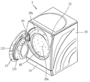
도 1은 본 발명의 일 실시예에 따른 의류처리장치를 보인 사시도.
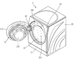
도 2a는 도 1에 도시된 도어가 1차로 회전되어 의류 투입구가 개방된 상태를 보인 개념도.
도 2b는 도 2a에 도시된 상태에서, 도어가 2차로 회전된 상태를 보인 개념도.
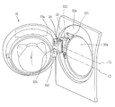
도 3a는 도 1에 도시된 의류처리장치의 분해 사시도.
도 3b는 도 1에 도시된 도어의 분해 사시도.
도 4a 및 도 4b는 도어와 힌지 유닛의 결합 상태를 보여주는 개념도.
도 5a는 도 3a의 힌지 유닛의 분해 사시도.
도 5b는 도 3a의 힌지 유닛의 측면도.
도 5c는 도 3a의 힌지 유닛의 사시도.
도 6a, 도 6b, 도 6c 및 도 6d는 도 4a의 힌지 유닛에 의하여 도어가 개방되는 동작을 나타내는 동작도들.
도 7은 본 발명의 다른 실시예를 나타내는 힌지 유닛의 분해 사시도.
도 8a, 도 8b, 도 8c 및 도 8d는 도 7의 힌지 유닛에 의하여 도어가 개방되는 동작을 나타내는 동작도들.1 is a perspective view showing a clothes processing apparatus according to an embodiment of the present invention;
FIG. 2A is a conceptual view showing a state in which the door shown in FIG. 1 is first rotated to open a clothes inlet. FIG.
FIG. 2B is a conceptual view showing a state in which the door is secondarily rotated in the state shown in FIG. 2A. FIG.
FIG. 3A is an exploded perspective view of the clothes processing apparatus shown in FIG. 1; FIG.
FIG. 3B is an exploded perspective view of the door shown in FIG. 1; FIG.
FIGS. 4A and 4B are conceptual views showing a combined state of the door and the hinge unit. FIG.
Figure 5A is an exploded perspective view of the hinge unit of Figure 3A;
Figure 5B is a side view of the hinge unit of Figure 3A.
Figure 5c is a perspective view of the hinge unit of Figure 3a;
FIGS. 6A, 6B, 6C and 6D are operational diagrams illustrating the operation of the door being opened by the hinge unit of FIG. 4A;
7 is an exploded perspective view of a hinge unit according to another embodiment of the present invention.
Figures 8A, 8B, 8C and 8D are operational diagrams illustrating the operation of the door being opened by the hinge unit of Figure 7;
이하, 본 발명에 관련된 의류처리장치에 대하여 도면을 참조하여 보다 상세하게 설명한다.DETAILED DESCRIPTION OF THE PREFERRED EMBODIMENTS A garment processing apparatus according to the present invention will be described below in detail with reference to the drawings.
단수의 표현은 문맥상 명백하게 다르게 뜻하지 않는 한, 복수의 표현을 포함한다.The singular expressions include plural expressions unless the context clearly dictates otherwise.
서로 다른 실시예라고 하더라도, 앞선 실시예와 동일하거나 유사한 구성요소에는 동일·유사한 도면 부호를 부여하고 이에 대한 중복되는 설명은 생략하기로 한다.In other respects, the same or similar reference numerals are given to the same or similar components to those of the previous embodiment, and a duplicate description thereof will be omitted.
본 명세서에 개시된 실시 예를 설명함에 있어서 관련된 공지 기술에 대한 구체적인 설명이 본 명세서에 개시된 실시 예의 요지를 흐릴 수 있다고 판단되는 경우 그 상세한 설명을 생략한다.In the following description of the embodiments of the present invention, a detailed description of related arts will be omitted when it is determined that the gist of the embodiments disclosed herein may be obscured.
첨부된 도면은 본 명세서에 개시된 실시 예를 쉽게 이해할 수 있도록 하기 위한 것일 뿐, 첨부된 도면에 의해 본 명세서에 개시된 기술적 사상이 제한되지 않으며, 본 발명의 사상 및 기술 범위에 포함되는 모든 변경, 균등물 내지 대체물을 포함하는 것으로 이해되어야 한다.It is to be understood that both the foregoing general description and the following detailed description are exemplary and explanatory and are intended to provide further explanation of the invention as claimed. It should be understood that it includes water and alternatives.
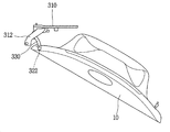
도 1은 본 발명의 일 실시예에 따른 의류처리장치(1)를 보인 사시도이고, 도 2a 및 도 2b는 도 1에 도시된 도어(10)가 각각 1차 및 2차로 회전되어 의류 투입구(20a)가 개방된 상태를 보인 개념도들이다.FIG. 1 is a perspective view showing a
본 도면들을 참조하면, 의류처리장치(1)는 본체(20) 및 도어(10)를 포함한다.Referring to these drawings, the
본체(20)는 의류처리장치(1)의 외형을 이루며, 의류가 투입되는 의류 투입구(20a)를 구비한다. 본 실시예에서는, 육면체 형상을 가지는 본체(20)의 전면부에 의류 투입구(20a)가 형성된 것을 보이고 있다.The
본체(20)의 내부에는 의류 투입구(20a)를 통하여 세탁물이 수용되는 의류 수용부가 구비된다.Inside the
일 예로, 본 발명의 의류처리장치(1)가 세탁물의 건조를 위한 장치로 구성될 경우, 의류 수용부는 본체(20)의 내부에 회전 가능하게 구비되는 드럼(40)으로 구성될 수 있다.For example, when the
다른 일 예로, 본 발명의 의류처리장치(1)가 세탁물의 세탁과 건조를 함께 수행 가능한 장치로 구성될 경우, 의류 수용부는 본체(20)의 내부에 구비되어 세탁수가 저장되는 터브(미도시) 및 상기 터브 내부에 회전 가능하게 구비되어 세탁물이 수용되는 드럼(40)으로 구성될 수 있다.In another embodiment, when the
본체(20)에는 드럼(40)을 회전시키도록 구성되는 구동유닛(미도시)이 구비된다. 구동유닛은 구동력을 발생시키는 모터 및 상기 구동력을 이용하여 드럼(40)을 회전시키는 벨트를 포함하여 구성될 수 있다.The
본체(20)에는 세제공급부(미도시)가 서랍식으로 인출 및 인입 가능하게 설치될 수 있다. 세제공급부를 커버하는 커버(21)는 상하방향으로 회전 가능하게 구성될 수 있다.A detergent supply unit (not shown) may be installed in the
본체(20)에는 전원 버튼(22)이 구비되어, 의류처리장치(1)의 전원을 온/오프시키도록 구성될 수 있다. 디스플레이부(12)가 터치스크린(12)으로 구성되는 경우, 상기 터치스크린(12)에 대한 터치 입력을 통하여 전원을 온/오프시키도록 구성될 수 있다[전원 버튼(22) 미구비].The
또한, 상기 도어(10)에는 윈도우부(11) 및 디스플레이부(12)가 구비될 수 있다.The
도어(10)가 닫힌 상태에서, 윈도우부(11)는 의류 투입구(20a)에 대응되게 배치되어, 의류 수용부를 들여다 볼 수 있도록 구성된다. 이에 따라, 사용자는 윈도우부(11)를 통하여 의류 수용부에 수용된 의류의 상태를 확인할 수 있다.In a state in which the
디스플레이부(12)는 의류처리장치(1)에서 처리되는 정보를 표시(출력)한다. 예를 들어, 디스플레이부(12)는 의류처리장치(1)에서 구동되는 행정(세탁, 탈수, 건조 행정 등)의 실행화면 정보, 또는 이러한 실행화면 정보에 대응되는 UI(User Interface), GUI(Graphic User Interface) 정보를 표시할 수 있다.The
한편, 도어(10)는 힌지 유닛(30, 또는 힌지부, 힌지 모듈)에 의해 본체(20)에 대하여 회전 가능하게 설치되어, 의류 투입구(20a)를 개폐하도록 구성된다. On the other hand, the
도어(10)의 일측에 힌지 유닛(30)이 장착된 구조에서, 도어(10)의 타측에는 도어(10)를 본체(20)에 고정 또는 고정해제하는 로킹장치가 구비된다. 로킹장치는 누름식으로 구성되어, 도어(10)의 타측을 한번 누르면 도어(10)가 잠금되고, 다시 한번 누르면 도어(10)가 잠금해제되도록 이루어질 수 있다.A locking device for fixing or releasing the
도시된 바와 같이, 본체(20)는 외부면에서 내측으로 리세스되고, 내부에 의류 투입구(20a)를 구비하는 도어 수용부(20b)를 구비할 수 있다. 도어(10)가 닫힌 상태에서, 도어(10)는 도어 수용부(20b)에 수용되고, 열린 상태에서는 상기 도어 수용부(20b)를 벗어나도록 배치될 수 있다. 이를 통하여, 도어(10)는 열린 상태에서 상기 의류 투입구(20a)를 개방하고, 닫힌 상태에서 상기 의류 투입구(20a)를 막게 된다.As shown in the figure, the
이처럼 도어(10)가 도어 수용부(20b)에 수용되는 구조상, 도어(10)의 개방시 도어(10)가 본체(20)에 걸림되지 않도록 하기 위하여, 일 예로서, 힌지 유닛(30)은 서로 다른 두 개의 회전축을 가지는 이중 힌지 구조를 가질 수 있다. 이 경우, 도 2a 및 도 2b에 도시된 바와 같이, 어느 하나의 회전축에 대한 1차 회전에 의해 도어(10)가 도어 수용부(20b)로부터 이격된 후, 다른 하나의 회전축에 대한 2차 회전에 의해 도어(10)가 회전되도록 구성될 수 있다.In order to prevent the
이러한 이중 힌지 구조에 의하여, 도어가 크고 전면과 도어 외면의 사이에 단차가 없는, 또는 도어 외면이 상기 도어 수용부로부터 돌출되지 않는 함몰형 도어에서도 90 도 이상으로 도어가 회전하여 의류 투입구를 개방시키는 메커니즘이 구현될 수 있다. With this double hinge structure, even if the door is large and there is no step between the front surface and the door outer surface, or the recessed door where the door outer surface does not protrude from the door receiving portion, the door rotates to 90 degrees or more, Mechanism can be implemented.
이하에서는, 이러한 이중 힌지 구조를 중심으로, 도어(10)의 상세 구조에 대하여 설명한다.Hereinafter, the detailed structure of the
도 3a은 도 1에 도시된 의류처리장치(1)의 분해 사시도이고, 도 3b는 도 1에 도시된 도어의 분해 사시도이며, 도 4a 및 도 4b는 도어와 힌지 유닛의 결합 상태를 보여주는 개념도이다.FIG. 3A is an exploded perspective view of the
의류 투입구는 원형으로 형성되고, 도어(10)가 이에 대응하도록 원형(정원형, 타원형 포함)으로 형성된 것을 보이고 있다. 그러나 본 발명이 반드시 이에 한정되는 것은 아니다. 의류 투입구와 도어(10)는 다각형(사각형, 육각형 등)으로 형성될 수도 있다.The garment input port is formed in a circular shape, and the
본 도면들을 참조하면, 도어(10)는 도어 프레임(110), 도어 윈도우(120) 및 도어 커버(140)를 포함한다. Referring to these drawings, the
도어 프레임(110)에는 도어(10)가 닫힌 상태에서 의류 투입구(20a)와 마주하는 개구부(110a)가 형성되고, 도어 윈도우(120)는 상기 개구부(110a)에 대응되도록 도어 프레임(110)에 설치된다. 도어 윈도우(120)는 투광성 재질(유리, 합성수지 재질 등)로 형성되어, 도어(10)가 닫힌 상태에서 의류 투입구(20a)에 대응되도록 배치된다. The
도시된 바와 같이, 도어 프레임(110)은 아우터 프레임(111)과 이너 프레임(112)을 포함하여 구성될 수 있다. 아우터 프레임(111)과 이너 프레임(112)은 합성수지 재질(예를 들어, ABS 재질, PC 재질 등)로 형성될 수 있다. As shown in the figure, the
도어 프레임(110)에는 도어 윈도우(120)가 장착된다. 도어 윈도우(120)는 투광성 재질(유리, 합성수지 재질 등)로 형성되어, 도어(10)가 닫힌 상태에서 의류 투입구(20a)에 대응되도록 배치된다. 또한, 도어 프레임(110)에는 도어(10)의 외관을 형성하는 도어 커버(140)가 결합된다. 도어 커버(140)는 투광성을 가지는 유리 재질 또는 합성수지 재질로 형성될 수 있다. A
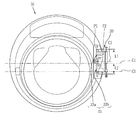
본 실시예에서는, 원형의 도어(10)에 대응되도록 도어 프레임(110)과 도어 커버(140)가 원형으로 형성된 것을 보이고 있다. 도시에 의하면, 도어 프레임(110)은 본체(20)에 회전 가능하게 결합되며, 이를 위하여 힌지 유닛(30)이 도어 프레임(110)과 본체(20)에 각각 결합된다. 이 경우에, 상기 힌지 유닛(30)은 상기 원형의 중심을 기준으로 상측에서 상기 본체(20)에 장착될 수 있다. 상기 힌지 유닛(30)과 상기 도어(10)는 상기 도어(10)의 수평 중심선(C1)에 대하여 상하 비대칭되는 연결지점들(P1, P2)에서 회전 가능하게 연결될 수 있다. 또한, 상기 힌지 유닛(30)은 상기 의류 투입구(20a) 의 수평 중심선(C2)에 대하여 편심되는 위치에 배치될 수 있다. 도 4a 및 도 4b를 참조하면, 상기 도어(10)와 상기 의류 투입구(20a)가 모두 원형이나, 상기 도어(10)의 일측에 디스플레이부(12)가 배치되므로, 상기 도어(10)는 상기 의류 투입구(20a)에 대하여 중심이 서로 다른 원형으로 이루어진다. 이러한 비대칭 구조에서 도어의 개방구조를 구현하기 위하여, 상기 힌지 유닛(30)은 상기 의류 투입구(20a) 의 수평 중심선(C2)에 대하여 상측으로 편심되는 위치에 배치되며, 특이한 구조를 가지게 된다. In this embodiment, the
도시에 의하면, 상기 힌지 유닛(30)과 상기 도어(20)는 상기 도어(20)의 수평 중심선(C1)에 대하여 상하 비대칭되는 연결지점들(P1, P2)에서 연결부(33)를 통하여 회전 가능하게 연결될 수 있다. The
상기 연결부(33)는 상기 도어(20)의 수평 중심선(C1)을 기준으로 상측에 배치되는 상측 연결부(33a)와 하측에 배치되는 하측 연결부(33b)를 구비할 수 있다. 이 때에, 상기 상측 연결부(33a) 및 하측 연결부(33b)는 각각 하나 또는 그 이상의 연결부를 구비할 수 있다. 도시에 의하면, 상기 상측 연결부(33a) 및 하측 연결부(33b)는 상기 도어(20)의 수평 중심선(C1)을 기준으로 비대칭되도록 배치될 수 있다. The
여기서 상기 연결지점들(P1, P2)은 상측 연결부(33a)의 상단지점과, 하측 연결부(33b)의 하단지점으로 정의될 수 있다. 예로서, 후술하는 상측 연결부(33a)의 상단에 위치한 부싱(334, 도 5a 참조)과 하측 연결부(33b)의 하단의 부싱의 위치가 상기 연결지점들(P1, P2)이 될 수 있다.Here, the connection points P1 and P2 may be defined as an upper end point of the upper connecting
다른 예로서, 상기 연결지점들(P1, P2)은 상측 연결부(33a)의 중간지점(중심)과 하측 연결부(33b)의 중간지점(중심)으로 정의될 수 있다. 이 경우에는, 후술하는 상측 연결부(33a)의 부싱들의 중간지점과 하측 연결부(33b)의 부싱들의 중간지점의 위치가 상기 연결지점들(P1, P2)이 될 수 있다.As another example, the connection points P1 and P2 may be defined as an intermediate point (center) between the intermediate point (center) of the upper connecting
보다 구체적으로, 상기 도어(20)의 수평 중심선(C1)으로부터 상기 상측 연결부(33a)까지의 거리(L1)가 상기 하측 연결부(33b)까지의 거리(L2)보다 더 크게 형성될 수 있다. 이 때에, 상기 상측 연결부(33a) 및 하측 연결부(33b)의 사이의 중간 지점(C3)은 상기 도어(20)의 수평 중심선(C1)보다 상측에 위치될 수 있다. More specifically, the distance L1 from the horizontal center line C1 of the
이와 같이 본 발명에서는, 힌지 유닛(30)이 도어(20)에 대하여 편심되는 위치에 배치되어, 원형의 도어와 의류 투입구가 중심이 서로 다른 위치이고, 도어에 디스플레이부가 구비되는 경우에 적합한 도어의 개폐 구조를 제공한다.As described above, according to the present invention, when the
이 경우에, 상기 힌지 유닛(30)의 중심은 상기 의류 투입구(20a)의 수평 중심선(C2)에 대하여 상측으로 편심되도록 배치될 수 있다. 이 경우에 상기 힌지 유닛(30)은 상기 힌지 유닛(30)의 도심이나 무게 중심이 상기 도어(20)의 수평 중심선(C1)이나 상기 의류 투입구(20a)의 수평 중심선(C2)에 대하여 편심되는 구조가 될 수 있다.In this case, the center of the
또한, 상기 도어 수용부(20b)에는 관통홀(23)이 형성되고, 상기 힌지 유닛(30)은 도어 수용부(20b)에 의하여 가려지며, 상기 힌지 유닛의 연결부는 상기 관통홀(23)을 관통하여 도어 수용부(20b)로 노출될 수 있다. 상기 연결부(33)와 마찬가지로, 상기 도어 수용부(20b)에 형성되는 관통홀(23)은 상기 도어(20)의 수평 중심선(C1)에 대하여 상하 비대칭으로 형성될 수 있다. 따라서, 상기 힌지 유닛(30)에서 상기 관통홀(23)을 관통하여 상기 도어 수용부(20b)로 노출되는 부분은 상기 의류 투입구(20a)의 수평 중심선(C2)에 대하여 비대칭되거나 상기 노출되는 부분의 중심은 상기 의류 투입구(20a)의 수평 중심선(C2)에 대하여 상측에 배치될 수 있다.The
상기에서 설명된 본 발명의 편심 구조에 의하여, 의류 투입구와 중심이 다르며, 상측의 무게가 더 무거운 원형 도어를 지지할 때에, 동작 신뢰도를 확보할 수 있는 힌지 유닛이 구현될 수 있다. According to the above-described eccentric structure of the present invention, a hinge unit can be realized that can assure operational reliability when supporting a round door which is different from the center of the garment input port and heavier on the upper side.
한편, 상기 편심되는 힌지 유닛의 구조는 단일 힌지뿐만 아니라 본 발명의 일 실시예로서 전술한 이중 힌지 구조에도 적용될 수 있으며, 이러한 힌지 유닛(30)의 상세 구조에 대하여는 후술한다.Meanwhile, the structure of the eccentric hinge unit can be applied not only to a single hinge but also to the double hinge structure described above as an embodiment of the present invention. The detailed structure of the
보다 구체적인 예로서, 본체(20)의 전면에는 전면 커버(21)가 장착되며, 상기 힌지 유닛(30)은 본체(20)의 내부에 장착되어 상기 전면 커버(21)를 관통하여 상기 도어(10)와 연결될 수 있다.A
도시에 의하면, 상기 전면 커버(21)에는 의류 투입구(20a)와 함께, 도 1 및 도 2를 참조하여 전술한 도어 수용부(20b)가 형성될 수 있다. 도어(10)가 닫힌 상태에서, 도어(10)는 도어 수용부(20b)에 수용되고, 도어(10)의 외부면 테두리 부분은 이에 인접한 본체(20)의 외부면과 동일 평면을 이루도록 배치될 수 있다.According to the illustrated embodiment, the
상기 관통홀(23)은 상기 도어 수용부(20b)의 측벽에 형성되며, 상기 힌지 유닛(30)은 상기 본체(20)에 구비된 힌지 브라켓(미도시)에 장착되고, 상기 힌지 유닛(30)의 적어도 일부가 상기 관통홀(23)을 통하여 상기 도어 수용부(20b)로 노출될 수 있다. 상기 힌지 브라켓은 의류처리장치의 본체와 힌지 유닛(30)을 연결하는 역할을 하게 된다. 이 경우에, 상기 힌지 브라켓은 의류 투입구(20a)의 중심을 기준으로 상측에 배치되며, 이를 통하여 힌지 유닛(30)은 상기 의류 투입구(20a)에 대하여 편심되는 위치에 배치될 수 있다. 도 1 및 도 2를 참조하여 전술한 바와 같이, 상기 힌지 유닛(30)의 일은 서예로서, 다른 두 개의 회전축을 가지는 이중 힌지 구조를 가질 수 있으며, 이를 통하여 상기 도어(10)가 90 도 이상으로 회전하여 도어 수용부(20b)로부터 벗어나게 된다. 이하 이러한 힌지 유닛(30)의 구조에 대하여 도 1 및 도 2와 함께, 도 5, 도 6a, 도 6b, 도 6c 및 도 6d를 참조하여 보다 상세히 설명한다.The through
도 5a는 도 3a의 힌지 유닛의 분해 사시도이고, 도 5b는 도 3a의 힌지 유닛의 측면도이고, 도 5c는 도 3a의 힌지 유닛의 사시도이며, 도 6a, 도 6b, 도 6c 및 도 6d는 도 4a의 힌지 유닛에 의하여 도어가 개방되는 동작을 나타내는 동작도들이다.Fig. 5A is an exploded perspective view of the hinge unit of Fig. 3A, Fig. 5B is a side view of the hinge unit of Fig. 3A, Fig. 5C is a perspective view of the hinge unit of Fig. 3A, and Figs. 6A, 6B, 6C, 4a are opened by the hinge unit 4a.
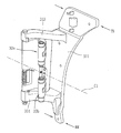
본 도면들을 참조하면, 상기 힌지 유닛(30)은 상기 본체에 장착되는 장착부(311)를 구비하며, 상기 장착부(311)는 하단부의 폭(BW)이 상단부의 폭(TW)보다 좁게 형성될 수 있다. 이 경우에, 상기 폭은 상기 도어를 정면에서 바라 보았을 때, 좌우방향의 폭이 거리가 될 수 있다. 이 때에, 상기 장착부(311)는 상기 도어(20)의 수평 중심선(C1)을 기준으로 하측의 면적이 상측의 면적보다 작게 형성될 수 있다. 이를 통하여, 상기 장착부(311)의 도심 또는 무게중심은 상기 도어(20)의 수평 중심선(C1)보다 상측에 위치하게 된다.The
또한, 상기 장착부(311)는 상기 도어(20)의 수평 중심선(C1)으로부터 상기 장착부(311)의 상단까지의 길이가 상기 도어(20)의 수평 중심선(C1)으로부터 상기 장착부(311)의 하단까지의 길이보다 길도록 이루어질 수 있다. 즉, 상기 장착부(311)는 상기 도어(20)의 수평 중심선(C1)에 대하여 편심되는 위치에 배치될 수 있다.The mounting
한편, 상기 장착부(311)의 구조는 전술한 도어(20)의 수평 중심선(C1)에 편심되는 힌지 유닛과 관련된 특징이나, 이하 설명되는 이중 힌지 구조에도 적용될 수 있다.Meanwhile, the structure of the mounting
구체적인 예로서, 상기 힌지 유닛(30)은 장착부(311)를 가지는 베이스부재(310)를 구비할 수 있다.As a specific example, the
상기 베이스부재(310)는 도어를 지지하는 강도와 도어의 개폐에도 변형이 되지 않도록 내구성을 가지는 금속 재질로 형성될 수 있다. 보다 구체적으로, 상기 베이스부재는 상기 장착부(311)에서 돌출되는 돌출부(312)를 구비한다. 예를 들어, 상기 장착부(311)에서 상기 도어의 수평 중심선(C1)에 대하여 상하 비대칭되도록 복수의 돌출부(313, 314)가 돌출될 수 있다.The
상기 장착부(311)는 의류처리장치의 본체에 장착되는 부분으로서, 예를 들어 힌지 브라켓에 장착된다. 이 경우에, 상기 힌지 유닛(30)이 상기 의류 투입구(20a)에 대하여 편심된 위치에 배치되므로, 상기 베이스부재(310)는 상기 도어(20)의 수평 중심선(C1)을 기준으로 상측으로 치우치도록 상기 본체, 구체적으로 힌지 브라켓에 장착될 수 있다. 이 경우에, 상기 베이스부재(310)의 복수의 돌출부(313, 314) 사이의 중심은 상기 의류투입구(20a)의 수평 중심선을(C2) 기준으로 상측으로 치우쳐서 상기 본체에 장착될 수 있다.The mounting
또한, 상기 장착부(311)는 판형부재로 이루어지며, 일변이 상기 의류투입구(20a)의 형상에 대응하도록 원호를 형성할 수 있다. 이 때에, 상기 베이스부재(310)가 상기 원형의 중심을 기준으로 상측에 위치하므로, 상기 일변은 원의 좌상측에 위치하는 원호를 따라 형성될 수 있다.In addition, the mounting
상기 돌출부(312)는 상기 장착부(311)에서 돌출되는 외팔보 형태로 이루어진다. 이 경우에, 상기 돌출부(312)는 상기 장착부(311)와 둔각을 이루는 방향으로 돌출될 수 있다. 예를 들어, 상기 돌출부(312)는 상기 의류 투입구 직경 방향을 따라 연장되면서 상기 본체(20)의 전면을 향하여 연장되어, 상기 전면 커버(21)의 관통홀(23)을 관통하여 도어 수용부(20b)로 돌출되도록 이루어진다.The
보다 구체적으로, 상기 돌출부(312)는 서로 이격되게 배치되는 제1돌출부분(313)과 제2돌출부분(314)을 구비할 수 있다. 도시에 의하면, 상기 제1돌출부분(313)은 상기 도어의 수평 중심선(C1)을 기준으로 상측에 배치되며, 상기 제2돌출부분(314)은 하측에 배치될 수 있다. 이 경우에, 상기 제1돌출부분(313)과 상기 제2돌출부분(314)은 후술하는 제1연결부(331)와 결합될 수 있다.More specifically, the
전술한 바와 같이, 상기 장착부(311)는 하단부의 폭이 상단부의 폭보다 좁게 형성될 수 있다. 상기 상단부는 상기 장착부(311)의 상단에 가까운 부분으로서, 본 예시에서는 상기 제1돌출부분(313)과 상기 장착부(311)의 상단의 사이가 될 수 있다. 또한, 상기 하단부는 상기 장착부(311)의 하단에 가까운 부분으로서, 본 예시에서는 상기 제2돌출부분(314)과 상기 장착부(311)의 하단의 사이가 될 수 있다.As described above, the width of the lower end portion of the mounting
이 경우에, 상기 제1돌출부분(313)과 제2돌출부분(314)은 모두 상기 의류 투입구(20a)의 중심보다 상측에 배치될 수 있다. 이 경우에, 제1돌출부분(313)과 제2돌출부분(314)은 각각 상기 장착부(311)에서 서로 이격 배치되며, 상기 장착부(311)는 상기 제1돌출부분(313)에서 상기 제2돌출부분(314)으로 갈수록 폭이 좁아지도록 형성될 수 있다. 예를 들어, 상기 제1돌출부분(313)에 해당하는 상기 장착부(311)의 폭은 상기 제2돌출부분(314)에 해당하는 상기 장착부(311)의 폭보다 넓도록 형성된다. 구체적으로, 상기 제1돌출부분(313)의 주변에서 상기 장착부(311)의 폭은 상기 제2돌출부분(314)의 주변에서 상기 장착부(311)의 폭보다 넓도록 형성될 수 있다.In this case, both the first projecting
상기 장착부(311)의 일변이 원호를 형성하므로, 장착부(311)의 폭이 변화하도록, 상기 장착부(311)의 타변은 상하방향을 따라 직선으로 형성될 수 있다. 이를 통하여 상기 의류 투입구(20a)의 중심에 대하여 상측에서 상기 중심을 향할수록 상기 장착부(311)의 폭이 좁아질 수 있다. Since the one side of the mounting
또한, 상기 장착부(311)는 상기 본체에 안착되는 면이 기울어지도록 형성될 수 있다. 예를 들어, 상기 장착부(311)의 상단부보다 하단부가 상기 연결부와 더 가까워지도록 상기 장착부(311)는 적어도 일부가 상기 연결부(33)의 회전축에 대하여 경사지도록 형성될 수 있다. 즉, 상기 연결부(33)는 수직방향으로 배치되고, 상기 장착부(311)는 상기 수직방향에 대하여 기설정된 각도(θ)로 기울어지도록 형성된다. 도시에 의하면, 상기 상단부와 하단부와 함께, 상기 제1돌출부분과 상기 제2돌출부분의 사이에 위치하는 부분이 모두 경사진 형태로 형성될 수 있다. 또한, 이에 대응하도록 상기 본체에서 상기 장착부가 안착되는 부분도 기울어진 형태로 형성될 수 있다.In addition, the mounting
상기 제1돌출부분(313)과 제2돌출부분(314)의 각 단부에는 힌지축이 삽입되는 삽입홀(315)이 형성될 수 있다. 상기 힌지축은 상기 본체(20)에 대하여 고정된 위치에 배치되며, 이중 힌지 구조의 어느 하나의 회전축을 형성하며, 따라서 제1회전축(321)으로 지칭될 수 있다.Each of the first and second projecting
도시에 의하면, 상기 힌지 유닛(30)은 연결부재(330)를 구비하며, 상기 연결부재(330)가 상기 돌출부(312)와 연결된다. 이 경우에 도어의 회전중심을 이동시키도록 상기 연결부재(330)는 상기 돌출부와 회전가능하게 연결될 수 있다.The
이 경우에, 상기 제1회전축(321)은 상기 연결부재(330)가 회전가능하게 연결되는 고정축이 될 수 있다. 상기 연결부재(330)는 상기 도어(10)의 닫힌 상태와 열린 상태의 사이에서 상기 도어(10)의 회전중심을 이동시키도록 이루어진다. 예를 들어, 상기 베이스부재(310)에는 상기 연결부재(330)의 제1연결부(331)가 연결되고, 상기 도어가 상기 연결부재의 제2연결부(332)와 회전가능하게 연결될 수 있다. In this case, the first
편심 힌지구조에 대한 예시에서, 전술한 연결부(33)는 제2연결부(332)가 될 수 있다. 이 때에, 상기 돌출부(312)의 일단에 상기 도어가 회전가능하게 결합되어 상기 돌출부(312)는 상기 연결부재(330)가 될 수 있다. 이 경우에, 상기 힌지 유닛(30)에서 상기 관통홀(23)을 관통하여 상기 도어 수용부로 노출되는 부분은 돌출부의 일부와 상기 돌출부의 단부에 구비되는 연결부가 될 수 있으며, 상기 돌출부의 일부와 상기 연결부는 상기 도어의 수평 중심선을 기준으로 비대칭되도록 배치될 수 있다.In the example of the eccentric hinge structure, the above-described connecting
이중 힌지 구조에서, 상기 연결부재(330)의 일단에는 상기 제1연결부(331)가 형성되고, 상기 제1연결부(331)는 상기 제1회전축(321)을 통하여 상기 베이스부재(310)에 회전가능하게 연결될 수 있다. 다른 예로서, 상기 제1연결부(331)는 상기 연결부재(330)를 상기 베이스부재(310)에 슬라이딩 이동가능하게 연결하도록 이루어지는 것도 가능하다. 이 경우에는 상기 제1회전축 대신에 연결부재(330)가 상기 베이스부재(310)의 돌출부에 슬라이딩 가능하게 결합된다. 이와 같이, 상기 제1연결부(331)는 상기 베이스부재(310)에 이동가능하게 결합될 수 있다.In the double hinge structure, the
상기 도어(10)의 닫힌 상태와 열린 상태의 사이에서 상기 도어(10)의 회전중심이 이동하도록, 상기 연결부재(330)의 타단에는 제2연결부(332)가 형성되고, 상기 제2연결부(332)에는 상기 도어(10)가 회전가능하게 연결될 수 있다.A second connecting
도시에 의하면, 상기 제2연결부(332)에는 제2회전축(322)이 장착되며, 상기 도어(10)의 회전에 따라 상기 도어(10)의 회전중심은 상기 제1연결부(또는 제1회전축)에서 상기 제2연결부(또는 제2회전축)으로 이동하게 된다.A
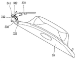
상기 제2회전축(333)에는 부싱(334)이 장착될 수 있으며, 상기 부싱(334)에 상기 도어(10)와의 결합을 위한 힌지 홀더(341, 도 3a 참조)가 결합된다. 상기 힌지 홀더(341)는 상기 도어(10)에 결합되며, 상기 힌지 홀더(341)를 가리기 위하여, 상기 도어에는 홀더 커버(342)가 상기 힌지 홀더(341)를 덮도록 장착될 수 있다.A
상기 연결부재(330)는 일 방향으로 연장되는 제1부재(335)과, 상기 제1부재의 단부에서 돌출되어 상기 일 방향과 다른 방향을 따라 연장되는 제2부재(336)를 포함할 수 있다. 이 경우에, 상기 제1부재(335)의 일단에 상기 제1회전축(321)이 연결되고, 상기 제1부재(335)의 타단에서 절곡되어 상기 다른 방향으로 제2부재(336)가 연장될 수 있다. 또한, 상기 제2부재(336)의 단부에 상기 제2회전축(322)이 장착되며, 상기 제2회전축(322)에 상기 도어가 회전가능하게 결합한다.The connecting
이 경우에, 상기 제1부재(335)는 직선의 바 형태로 이루어지고, 상기 제2부재(336)는 곡선의 바 형태로 이루어진다. 보다 구체적으로, 상기 제2부재(336)는 상기 제1연결부(331)를 중심으로 하는 원호를 형성한다. 따라서, 상기 제2부재(336)는 상기 제1연결부(331)를 중심으로 하는 원주 방향을 따라 연장될 수 있다.In this case, the
한편, 상기 힌지 유닛(30)은 상기 디스플레이부(12, 도 1 참조)를 상기 본체에 구비되는 제어부(메인 회로기판)와 전기적으로 연결하는 전기배선의 적어도 일부를 수용하도록 형성된다. 예를 들어, 상기 힌지 유닛의 적어도 일부에는 상기 전기배선을 수용하는 수용홈(337)이 형성될 수 있다. 구체적으로, 상기 제2부재(336)에는 전기배선을 수용하는 상기 수용홈(337)이 형성되고, 상기 수용홈(337)을 덮는 커버(338)가 상기 힌지 유닛(30)에 장착될 수 있다. 상기 수용홈(337)은 상기 제1부재(335)로 연장되며, 이를 통하여 상기 전기배선은 상기 제1연결부(331)를 지나서 의류처리장치의 내부로 이어질 수 있다. 상기 전기배선은 도어를 의류처리장치의 내부의 제어부와 전기적으로 연결하는 경로로서 구비될 수 있다.Meanwhile, the
이 때에, 상기 연결부재(330)는 상기 도어의 수평 중심선을 기준으로 비대칭되도록 배치되는 상측 연결부재(330a) 및 하측 연결부재(330b)를 구비할 수 있으며, 상기 전기배선은 상기 상측 연결부재(330a)를 통하여 상기 본체로 이어질 수 있다. 즉, 상기 전기배선을 수용하는 수용홈(337)은 상기 상측 연결부재(330a)에 형성될 수 있다. 보다 구체적으로, 상기 제2부재(336)가 상기 도어의 수평 중심선을 기준으로 상하에 각각 배치되는 상측 부재 및 하측 부재를 구비하며. 상기 수용홈(337)은 상기 상측 부재에 형성될 수 있다. 이를 통하여, 의류처리장치의 내외부를 연결하는 전기배선의 경로를 보다 용이하게 확보될 수 있다.At this time, the
다시, 이중 힌지 구조에 대하여 설명하면, 상기 제1부재(335)는 도어의 닫힌 상태에서 상기 제1연결부(331)로부터 상기 도어(10)의 후면과 가까워지는 방향으로 돌출되도록 이루어진다. 이에 반해, 상기 제2부재(336)는 상기 닫힌 상태에서 상기 제1부재(335)의 단부에서 상기 도어의 전면과 가까워지는 방향으로 돌출될 수 있다. The
상기 제1부재(335)와 제2부재(336)는 사이각이 예각을 이루도록 배치될 수 있다. 이때에, 상기 제2부재(336)는 상기 돌출부와 교차하도록 형성되며, 이를 통하여 상기 도어에서 상기 제1연결부(331)에 가까운 일측이 상기 제1연결부(331)의 우측에 배치될 수 있다. The
상기에서 설명된 구조를 가진 연결부재(330)는, 상기 도어가 닫힌 상태(도 6a)로부터 회전함에 따라 상기 제1연결부(331)를 중심으로 기설정된 범위에서 회전하도록 형성될 수 있다. 이 경우에, 상기 제1연결부(331)는 상기 제1회전축(321)을 중심으로 상기 연결부재가 기설정된 각도까지 회전하도록 형성될 수 있다. The connecting
한편, 도 6a, 도 6b 및 도 6c를 참조하면, 상기 연결부재(330)의 적어도 일부는 상기 도어의 회전에 의하여 상기 기설정된 범위내에서 상기 베이스부재의 적어도 일부를 지나가도록 형성된다. 예를 들어, 제2부재(336)와 제1부재(335)가 차례로 상기 돌출부를 지나서 회전하게 된다.6A, 6B and 6C, at least a part of the connecting
이와 같이, 제2부재(336)와 제1부재(335)가 차례로 상기 돌출부(312)를 지나서 회전하면, 이는 상기 기설정된 범위의 경계(본 예시에서는 75도)까지 열린 상태(도 6c, 이하, 중간 열린 상태라 한다)가 된다. 이 때에, 상기 제1연결부(331)에는 상기 경계에서 상기 연결부재가 상기 도어를 개방하는 방향으로 회전하는 것을 제한하는 스토퍼(미도시)가 구비될 수 있다 도시에 의하면, 상기 중간 열린 상태는 상기 도어(10)가 상기 의류 투입구(20a)를 정면에서 일부 가리는 상태가 된다.As described above, when the
이 때에, 상기 제2회전축(322)은 상기 도어(10)가 상기 중간 열린 상태로 회전함에 따라 상기 기설정된 각도까지 상기 제1회전축(321)을 중심으로 회전하여 상기 의류 투입구(20a)와 멀어지는 방향으로 이동하게 된다.At this time, the
상기 중간 열린 상태에서 상기 제1회전축(321)을 중심으로 도어(10)가 계속 회전하면, 전면 커버(21)와 도어(10) 외면의 사이에 단차가 없으므로 상기 도어의 일측이 상기 전면 커버(21)에 걸림될 수 있다. 본 예시의 이중 힌지 구조는, 상기 도어(10)의 회전중심은 상기 중간 열린 상태에서 상기 제1연결부(331)에서 상기 제2연결부(332)로 이동하도록 이루어진다. When the
예를 들어, 상기 중간 열린 상태에서 상기 제1회전축(321)을 중심으로 상기 도어(10)의 회전이 제한되므로, 도어(10)에 외력이 가해지면 도 6d와 같이 상기 도어는 상기 제2회전축(322)을 중심으로 회전하게 된다. 예를 들어, 상기 제2회전축(322)을 중심으로 한 도어(10)의 회전이 특정각도(본 예시에서는 45도)만큼 가능하다면, 상기 도어(10)는 상기 중간 열린 상태로부터 상기 특정각도만큼 더 회전하여 상기 의류 투입구를 정면에서 가리지 않는 상태(열린 상태)까지 개방시킨다.For example, in the middle open state, the rotation of the
이상에서는, 도어(10)를 여는 동작을 중심으로 이중 힌지 구조에 대하여 설명하였으나, 도어(10)를 닫는 동작은 상기 설명과 역으로 성립될 수 있다. 예를 들어, 열린 상태에서 도어(10)를 닫는 방향으로 상기 도어에 외력이 가해지면, 상기 중간 열린 상태까지는 상기 도어(10)가 상기 제2회전축(322)을 중심으로 회전한다. 상기 외력이 계속 가해지면, 상기 중간 열린 상태에서 상기 닫힌 상태까지는 상기 연결 부재(330)가 상기 도어(10)와 함께 상기 제1회전축(321)을 중심으로 회전하여 상기 도어 수용부(20b)에 수용된다.Although the double hinge structure has been described above with reference to the operation of opening the
상기에서 설명된 구조 및 동작에 의하여 본체에 대하여 돌출되지 않는 함몰형 도어임에도, 의류 투입구를 개폐할 수 있는 의류처리장치가 구현될 수 있다.A garment processing apparatus capable of opening and closing a garment input port can be realized even in the case of a recessed door that does not protrude from the main body due to the structure and operation described above.
한편, 상기에서 설명된 힌지 유닛의 구조는 여러가지 형태로 변형될 수 있다. 이하, 이러한 변형예에 대하여 도면을 참조하여 보다 상세히 설명한다.Meanwhile, the structure of the hinge unit described above can be modified into various forms. Hereinafter, these modified examples will be described in detail with reference to the drawings.
도 7은 본 발명의 다른 실시예를 나타내는 힌지 유닛의 분해 사시도이며, 도 8a, 도 8b, 도 8c 및 도 8d는 도 7의 힌지 유닛에 의하여 도어가 개방되는 동작을 나타내는 동작도들이다.FIG. 7 is an exploded perspective view of a hinge unit according to another embodiment of the present invention, and FIGS. 8A, 8B, 8C and 8D are operation diagrams showing an operation in which a door is opened by the hinge unit of FIG.
본 예시의 힌지 유닛은 도 5를 참조하여 전술한 힌지 유닛과 마찬가지로, 베이스부재(310), 연결부재(330), 제1회전축(321) 및 제2회전축(322)을 구비하며, 이들의 구조에 대한 설명은 전술한 내용으로 갈음한다. 예를 들어, 베이스부재(310)는 장착부(311)와 돌출부(312a)를 구비하고, 연결부재(330)는 제1부재(335)와 제2부재(336)를 구비하며, 제1회전축(321)이 제1연결부(331)를 형성하고, 제2회전축(322)이 제2연결부(332)를 형성할 수 있다. 상기 돌출부(312a)는 제1돌출부분(313)과 제2돌출부분(314a)을 구비한다. 또한, 닫힌 상태에서 열린 상태로 도어가 회전함에 따라 회전중심이 제1회전축(321)에서 제2회전축(322)으로 이동하게 된다.5, the hinge unit of the present embodiment includes a
도시에 의하면, 상기 힌지 유닛은 회전 가이드부(340)를 더 포함할 수 있다. 상기 연결부재는 상기 제1부재(335)와 제2부재(336)가 각각 바 형태로 연장되는 구조이므로 도어의 중량으로 인하여 상기 제1연결부(331)에서 큰 굽힘 모멘트가 발생할 수 있다. 따라서, 상기 회전 가이드부(340)는 상기 제1연결부(331)에 대한 강도를 보강하는 구조로 형성될 수 있다.According to the illustrated embodiment, the hinge unit may further include a
예를 들어, 상기 돌출부(312a), 구체적으로는 제2돌출부분(314a)에는 가이드 홈(341)이 형성될 수 있다. 이를 위하여, 상기 제2돌출부분(314a)은 도 5를 참조하여 설명한 베이스부재(310)의 돌출부(312)보다 넓은 면적을 가지도록 이루어질 수 있다. 도시에 의하면, 상기 제1부재(335)와 상기 제2부재(336)가 연결되는 부분에는 상기 가이드 홈(341)에 삽입되는 가이드 돌기(342)가 배치될 수 있다. 상기 가이드 홈(341)은 상기 제1회전축(321)을 중심으로 한 원호를 이루도록 형성될 수 있다. 이 경우에, 상기 연결부재(330)는 상기 가이드 돌기(342)가 상기 가이드 홈(341)의 단부에 위치할 때까지 회전하게 된다. 따라서 상기 가이드 홈(341)이 스토퍼의 역할을 하며, 상기 연결부재(330)의 회전량을 결정하게 된다. For example, the
이를 통하여 도 8a 내지 도 8d에 도시된 바와 같이, 상기 가이드 돌기(342)는 상기 가이드 홈(341)을 따라 이동하면서 상기 제1회전축(321)을 중심으로 회전하게 된다. 8A to 8D, the
이와 같은 구조에 의하면, 상기 도어가 열린 상태에서 중간 열린 상태의 사이에서 회전하는 경우에 상기 회전 가이드부(340)에 의하여 상기 도어의 회전이 가이드 될 뿐만 아니라, 상기 제1연결부(331)에 가해지는 굽힘 모멘트가 분산되는 효과를 가져온다. 따라서, 본 예시에 의하면, 보다 컴팩트한 힌지 구조에서도 함몰형 도어의 개폐 신뢰도가 향상된 의류처리장치가 구현될 수 있다.According to this structure, when the door rotates between the open state and the intermediate open state, the rotation of the door is guided by the
이상에서 설명한 의류처리장치는 위에서 설명된 실시예들의 구성과 방법에 한정되는 것이 아니라, 상기 실시예들은 다양한 변형이 이루어질 수 있도록 각 실시예들의 전부 또는 일부가 선택적으로 조합되어 구성될 수도 있다.The clothes processing apparatus described above is not limited to the configuration and method of the embodiments described above, but the embodiments may be configured by selectively combining all or a part of each embodiment so that various modifications can be made.
Claims (20)
디스플레이부를 구비하며, 상기 의류 투입구의 중심과 다른 위치에 중심을 가지는 원형으로 형성되어 상기 의류 투입구를 개폐하는 도어; 및
상기 본체에 장착되는 장착부를 구비하며, 상기 도어를 상기 본체에 회전 가능하게 연결하는 힌지 유닛을 포함하며,
상기 장착부는 하단부의 폭이 상단부의 폭보다 좁게 형성되는 것을 특징으로 하는 의류처리장치.A body having a circular garment inlet;
A door which is formed in a circular shape having a center at a position different from the center of the garment input port and opens and closes the garment input port, And
And a hinge unit rotatably connecting the door to the main body, the hinge unit having a mounting portion mounted on the main body,
Wherein the width of the lower end portion of the mounting portion is narrower than the width of the upper end portion.
상기 장착부는 상기 도어의 수평 중심선을 기준으로 하측의 면적이 상측의 면적보다 작게 형성되는 것을 특징으로 하는 의류처리장치.The method according to claim 1,
Wherein the mounting portion is formed such that an area of a lower side with respect to a horizontal center line of the door is smaller than an area of an upper side.
상기 장착부는 일방향을 따라 폭이 변화하도록 형성되는 것을 특징으로 하는 의류처리장치.3. The method of claim 2,
Wherein the mounting portion is formed to have a width varying along one direction.
상기 장착부는 상기 도어의 수평 중심선으로부터 상기 장착부의 상단까지의 길이가 상기 장착부의 하단까지의 길이보다 길도록 형성되는 것을 특징으로 하는 의류처리장치.The method according to claim 1,
Wherein the mounting portion is formed such that a length from a horizontal center line of the door to an upper end of the mounting portion is longer than a length to a lower end of the mounting portion.
상기 장착부에서 상기 도어의 수평 중심선에 대하여 상하 비대칭되도록 복수의 돌출부가 돌출되는 것을 특징으로 하는 의류처리장치.The method according to claim 1,
And a plurality of protrusions protruding from the mounting portion to be vertically asymmetric with respect to a horizontal center line of the door.
상기 돌출부는 상기 도어의 수평 중심선을 기준으로 상측에 배치되는제1돌출부분과 하측에 배치되는 제2돌출부분을 구비하는 것을 특징으로 하는 의류처리장치.6. The method of claim 5,
Wherein the protruding portion has a first protruding portion disposed on the upper side and a second protruding portion disposed on the lower side with respect to the horizontal center line of the door.
상기 제1돌출부분에 해당하는 상기 장착부의 폭은 상기 제2돌출부분에 해당하는 장착부의 폭보다 넓도록 형성되는 것을 특징으로 하는 의류처리장치.The method according to claim 6,
And the width of the mounting portion corresponding to the first protruding portion is formed to be wider than the width of the mounting portion corresponding to the second protruding portion.
상기 장착부는 상기 제1돌출부분에서 상기 제2돌출부분으로 갈수록 폭이 좁아지도록 형성되는 것을 특징으로 하는 의류처리장치.The method according to claim 6,
Wherein the mounting portion is formed so as to have a narrower width from the first projecting portion to the second projecting portion.
상기 복수의 돌출부에는 상기 도어가 회전가능하게 연결되는 연결부재가 장착되거나, 상기 복수의 돌출부의 단부에 상기 도어가 회전가능하게 연결되는 것을 특징으로 하는 의류처리장치.6. The method of claim 5,
Wherein the door is rotatably connected to the plurality of protrusions, or the door is rotatably connected to an end of the plurality of protrusions.
상기 장착부의 일변은 원호를 형성하고 타변은 직선으로 형성되는 것을 특징으로 하는 의류처리장치.The method according to claim 1,
Wherein one side of the mounting portion forms an arc and the other side is formed in a straight line.
상기 장착부는 도심 또는 무게중심이 상기 도어의 수평 중심선보다 상측에 위치하도록 형성되는 것을 특징으로 하는 의류처리장치.The method according to claim 1,
Wherein the mounting portion is formed so that a center of gravity or a center of gravity thereof is positioned above a horizontal center line of the door.
상기 장착부는 수직방향에 대하여 기설정된 각도로 기울어지도록 형성되는 것을 특징으로 하는 의류처리장치.12. The method of claim 11,
Wherein the mounting portion is formed to be inclined at a predetermined angle with respect to the vertical direction.
상기 힌지 유닛은,
상기 장착부를 구비하며, 상기 본체에 결합되는 베이스부재; 및
상기 베이스부재에 연결되는 제1연결부와, 상기 도어가 회전가능하게 연결되는 제2연결부를 구비하는 연결부재를 포함하는 의류처리장치.The method according to claim 1,
The hinge unit includes:
A base member having the mounting portion and coupled to the main body; And
And a connecting member having a first connecting portion connected to the base member and a second connecting portion rotatably connected to the door.
상기 제1연결부는 상기 베이스부재에 이동가능하게 결합되는 것을 특징으로 하는 의류처리장치.14. The method of claim 13,
Wherein the first connection portion is movably coupled to the base member.
상기 힌지 유닛은 상기 디스플레이부를 상기 본체에 구비되는 제어부와 전기적으로 연결하는 전기배선의 적어도 일부를 수용하도록 형성되는 것을 특징으로 하는 의류처리장치.The method according to claim 1,
Wherein the hinge unit is formed to receive at least a part of an electric wire electrically connecting the display unit to a control unit provided in the main body.
디스플레이부를 구비하며, 상기 의류 투입구의 중심과 다른 위치에 중심을 가지는 원형으로 형성되어 상기 의류 투입구를 개폐하는 도어; 및
상기 본체에 장착되는 장착부를 구비하며, 상기 도어를 상기 본체에 회전 가능하게 연결하는 힌지 유닛을 포함하며,
상기 장착부는 상기 도어의 수평 중심선으로부터 상기 장착부의 상단까지의 길이가 상기 도어의 수평 중심선으로부터 상기 장착부의 하단까지의 길이보다 길도록 이루어지는 것을 특징으로 하는 의류처리장치.A body having a circular garment inlet;
A door which is formed in a circular shape having a center at a position different from the center of the garment input port and opens and closes the garment input port, And
And a hinge unit rotatably connecting the door to the main body, the hinge unit having a mounting portion mounted on the main body,
Wherein the mounting portion has a length from a horizontal center line of the door to an upper end of the mounting portion is longer than a length from a horizontal center line of the door to a lower end of the mounting portion.
상기 장착부는 하단부의 폭이 상단부의 폭보다 좁게 형성되는 것을 특징으로 하는 의류처리장치.17. The method of claim 16,
Wherein the width of the lower end portion of the mounting portion is narrower than the width of the upper end portion.
상기 장착부는 상기 도어의 수평 중심선을 기준으로 하측의 면적이 상측의 면적보다 작게 형성되는 것을 특징으로 하는 의류처리장치.18. The method of claim 17,
Wherein the mounting portion is formed such that an area of a lower side with respect to a horizontal center line of the door is smaller than an area of an upper side.
상기 장착부는 일방향을 따라 폭이 변화하도록 형성되는 것을 특징으로 하는 의류처리장치.19. The method of claim 18,
Wherein the mounting portion is formed to have a width varying along one direction.
상기 장착부에서 상기 도어의 수평 중심선에 대하여 상하 비대칭되도록 복수의 돌출부가 돌출되는 것을 특징으로 하는 의류처리장치.17. The method of claim 16,
And a plurality of protrusions protruding from the mounting portion to be vertically asymmetric with respect to a horizontal center line of the door.
Priority Applications (8)
| Application Number | Priority Date | Filing Date | Title |
|---|---|---|---|
| CN201610460998.2A CN106012440B (en) | 2015-11-02 | 2016-06-23 | Device for clothing processing |
| CN201620630985.0U CN205893724U (en) | 2015-11-02 | 2016-06-23 | Clothes treatment device |
| EP16196298.0A EP3168359B1 (en) | 2015-11-02 | 2016-10-28 | Laundry treating apparatus |
| US15/339,055 US10344422B2 (en) | 2015-11-02 | 2016-10-31 | Laundry treating apparatus |
| AU2016350669A AU2016350669B2 (en) | 2015-11-02 | 2016-10-31 | Clothes treating apparatus |
| PCT/KR2016/012367 WO2017078347A1 (en) | 2015-11-02 | 2016-10-31 | Clothes treating apparatus |
| JP2018542084A JP7136698B2 (en) | 2015-11-02 | 2016-10-31 | clothing processing equipment |
| RU2018120312A RU2693869C1 (en) | 2015-11-02 | 2016-10-31 | Clothing processing device |
Applications Claiming Priority (4)
| Application Number | Priority Date | Filing Date | Title |
|---|---|---|---|
| US201562249355P | 2015-11-02 | 2015-11-02 | |
| US62/249,355 | 2015-11-02 | ||
| KR20160001184 | 2016-01-05 | ||
| KR1020160001184 | 2016-01-05 |
Publications (2)
| Publication Number | Publication Date |
|---|---|
| KR20170051148A true KR20170051148A (en) | 2017-05-11 |
| KR101815102B1 KR101815102B1 (en) | 2018-01-05 |
Family
ID=58741892
Family Applications (4)
| Application Number | Title | Priority Date | Filing Date |
|---|---|---|---|
| KR1020160040457A KR101815103B1 (en) | 2015-11-02 | 2016-04-01 | Laundry treating apparatus |
| KR1020160040456A KR101815102B1 (en) | 2015-11-02 | 2016-04-01 | Laundry treating apparatus |
| KR1020160040455A KR101815101B1 (en) | 2015-11-02 | 2016-04-01 | Laundry treating apparatus |
| KR1020160066813A KR102643352B1 (en) | 2016-01-05 | 2016-05-30 | Laundry treating apparatus |
Family Applications Before (1)
| Application Number | Title | Priority Date | Filing Date |
|---|---|---|---|
| KR1020160040457A KR101815103B1 (en) | 2015-11-02 | 2016-04-01 | Laundry treating apparatus |
Family Applications After (2)
| Application Number | Title | Priority Date | Filing Date |
|---|---|---|---|
| KR1020160040455A KR101815101B1 (en) | 2015-11-02 | 2016-04-01 | Laundry treating apparatus |
| KR1020160066813A KR102643352B1 (en) | 2016-01-05 | 2016-05-30 | Laundry treating apparatus |
Country Status (3)
| Country | Link |
|---|---|
| JP (3) | JP7136698B2 (en) |
| KR (4) | KR101815103B1 (en) |
| AU (3) | AU2016350668B2 (en) |
Families Citing this family (3)
| Publication number | Priority date | Publication date | Assignee | Title |
|---|---|---|---|---|
| CN111648100B (en) * | 2019-02-15 | 2023-06-13 | 重庆海尔洗衣机有限公司 | Wall-mounted washing machine |
| JP7329369B2 (en) * | 2019-06-18 | 2023-08-18 | シャープ株式会社 | electrical equipment |
| CN116209803A (en) * | 2020-09-23 | 2023-06-02 | 夏普株式会社 | Drum type washing machine |
Family Cites Families (19)
| Publication number | Priority date | Publication date | Assignee | Title |
|---|---|---|---|---|
| US3042471A (en) * | 1959-11-16 | 1962-07-03 | Gen Motors Corp | Flexible conduit hinge for domestic appliances |
| KR100260581B1 (en) * | 1998-06-05 | 2000-07-01 | 심명섭 | A processor cartrage and forming unit equipped therewith |
| KR200228519Y1 (en) * | 1998-06-18 | 2001-09-17 | 윤종용 | Door hinge of drum washing machine |
| KR200245382Y1 (en) * | 2001-05-25 | 2001-10-29 | 정창덕 | A custody cabinet of compact disk |
| US7581414B2 (en) * | 2002-01-09 | 2009-09-01 | Lg Electronics Inc. | Door for washing machine and dryer and washing machine and dryer having the same |
| KR200281165Y1 (en) * | 2002-04-12 | 2002-07-13 | 정두영 | A mounting plate of a kitchen furniture hinge |
| JP3801167B2 (en) * | 2003-11-14 | 2006-07-26 | 松下電器産業株式会社 | Drum washing machine |
| US10001282B2 (en) * | 2004-08-27 | 2018-06-19 | Arcelik Anonim Sirketi | Household appliance |
| DE102005015551B4 (en) * | 2005-04-04 | 2008-08-07 | Miele & Cie. Kg | Front-loading laundry machine such as washing machine, tumble dryer or washer-dryer |
| KR100834946B1 (en) | 2007-05-28 | 2008-06-03 | 엘지전자 주식회사 | Washing machine |
| CN101333753B (en) * | 2007-06-29 | 2011-09-14 | 海尔集团公司 | Hinge device capable of opening door of washing machine in large angle |
| CA2610078A1 (en) * | 2007-11-09 | 2009-05-09 | Mabe Canada Inc. | Clothes dryer door hinge |
| JP4907627B2 (en) * | 2008-10-16 | 2012-04-04 | パナソニック株式会社 | Drum washing machine |
| GB0902619D0 (en) * | 2009-02-17 | 2009-04-01 | Xeros Ltd | Cleaning apparatus |
| WO2011014018A2 (en) * | 2009-07-30 | 2011-02-03 | Lg Electronics Inc. | Washing machine |
| KR101643633B1 (en) * | 2009-07-30 | 2016-08-10 | 엘지전자 주식회사 | Washing machine |
| KR20150006264A (en) * | 2013-07-08 | 2015-01-16 | 삼성전자주식회사 | Drum Washing machine |
| KR102127719B1 (en) * | 2013-07-08 | 2020-06-29 | 삼성전자주식회사 | Washing machine |
| KR102158689B1 (en) * | 2013-11-04 | 2020-09-22 | 엘지전자 주식회사 | Connector and Laundry Treating Apparatus having the same |
-
2016
- 2016-04-01 KR KR1020160040457A patent/KR101815103B1/en active IP Right Grant
- 2016-04-01 KR KR1020160040456A patent/KR101815102B1/en active IP Right Grant
- 2016-04-01 KR KR1020160040455A patent/KR101815101B1/en active IP Right Grant
- 2016-05-30 KR KR1020160066813A patent/KR102643352B1/en active IP Right Grant
- 2016-10-31 JP JP2018542084A patent/JP7136698B2/en active Active
- 2016-10-31 AU AU2016350668A patent/AU2016350668B2/en active Active
- 2016-10-31 JP JP2018542085A patent/JP6938522B2/en active Active
- 2016-10-31 JP JP2018542083A patent/JP6892453B2/en active Active
- 2016-10-31 AU AU2016350669A patent/AU2016350669B2/en active Active
- 2016-10-31 AU AU2016350670A patent/AU2016350670B2/en active Active
Also Published As
| Publication number | Publication date |
|---|---|
| JP6938522B2 (en) | 2021-09-22 |
| JP2018532549A (en) | 2018-11-08 |
| AU2016350670B2 (en) | 2019-10-17 |
| JP2018532550A (en) | 2018-11-08 |
| AU2016350670A1 (en) | 2018-05-24 |
| KR102643352B1 (en) | 2024-03-07 |
| KR101815102B1 (en) | 2018-01-05 |
| KR20170051147A (en) | 2017-05-11 |
| JP6892453B2 (en) | 2021-06-23 |
| KR20170051149A (en) | 2017-05-11 |
| KR101815101B1 (en) | 2018-01-05 |
| AU2016350669B2 (en) | 2019-01-31 |
| AU2016350668A1 (en) | 2018-05-17 |
| KR20170082110A (en) | 2017-07-13 |
| AU2016350668B2 (en) | 2019-04-18 |
| KR101815103B1 (en) | 2018-01-05 |
| JP7136698B2 (en) | 2022-09-13 |
| JP2018532551A (en) | 2018-11-08 |
| AU2016350669A1 (en) | 2018-05-24 |
Similar Documents
| Publication | Publication Date | Title |
|---|---|---|
| US10711389B2 (en) | Door hinge of a laundry treating apparatus | |
| US10815602B2 (en) | Laundry treating apparatus | |
| CN111549499B (en) | Washing machine | |
| US9605372B2 (en) | Laundry treatment apparatus | |
| US10344422B2 (en) | Laundry treating apparatus | |
| KR101815101B1 (en) | Laundry treating apparatus | |
| JP2015043800A (en) | Drum type washing machine | |
| RU2689515C1 (en) | Clothing processing device | |
| KR100834946B1 (en) | Washing machine |
Legal Events
| Date | Code | Title | Description |
|---|---|---|---|
| A201 | Request for examination | ||
| A302 | Request for accelerated examination | ||
| E902 | Notification of reason for refusal | ||
| E902 | Notification of reason for refusal | ||
| E902 | Notification of reason for refusal | ||
| E902 | Notification of reason for refusal | ||
| E701 | Decision to grant or registration of patent right |