KR20170048573A - Method and system for generating a mechanical output and producing reaction products in a parallel manner - Google Patents
Method and system for generating a mechanical output and producing reaction products in a parallel manner Download PDFInfo
- Publication number
- KR20170048573A KR20170048573A KR1020177009284A KR20177009284A KR20170048573A KR 20170048573 A KR20170048573 A KR 20170048573A KR 1020177009284 A KR1020177009284 A KR 1020177009284A KR 20177009284 A KR20177009284 A KR 20177009284A KR 20170048573 A KR20170048573 A KR 20170048573A
- Authority
- KR
- South Korea
- Prior art keywords
- gas
- reactor
- combustion
- exhaust gas
- power
- Prior art date
Links
- 238000000034 method Methods 0.000 title claims abstract description 87
- 239000007795 chemical reaction product Substances 0.000 title description 16
- 238000002485 combustion reaction Methods 0.000 claims abstract description 262
- 230000008569 process Effects 0.000 claims abstract description 64
- 239000000446 fuel Substances 0.000 claims abstract description 58
- 238000004519 manufacturing process Methods 0.000 claims abstract description 55
- 229930195733 hydrocarbon Natural products 0.000 claims abstract description 23
- 150000002430 hydrocarbons Chemical class 0.000 claims abstract description 23
- 239000007789 gas Substances 0.000 claims description 347
- 238000010438 heat treatment Methods 0.000 claims description 17
- 238000006243 chemical reaction Methods 0.000 claims description 16
- 239000000203 mixture Substances 0.000 claims description 13
- VNWKTOKETHGBQD-UHFFFAOYSA-N methane Chemical compound C VNWKTOKETHGBQD-UHFFFAOYSA-N 0.000 claims description 12
- 239000002918 waste heat Substances 0.000 claims description 11
- 239000004215 Carbon black (E152) Substances 0.000 claims description 6
- 239000003345 natural gas Substances 0.000 claims description 3
- 239000003054 catalyst Substances 0.000 claims description 2
- 239000008246 gaseous mixture Substances 0.000 claims 1
- 238000010248 power generation Methods 0.000 claims 1
- 239000001301 oxygen Substances 0.000 description 27
- 229910052760 oxygen Inorganic materials 0.000 description 27
- QVGXLLKOCUKJST-UHFFFAOYSA-N atomic oxygen Chemical compound [O] QVGXLLKOCUKJST-UHFFFAOYSA-N 0.000 description 26
- 230000005855 radiation Effects 0.000 description 24
- 238000004230 steam cracking Methods 0.000 description 15
- UGFAIRIUMAVXCW-UHFFFAOYSA-N Carbon monoxide Chemical compound [O+]#[C-] UGFAIRIUMAVXCW-UHFFFAOYSA-N 0.000 description 12
- 238000005265 energy consumption Methods 0.000 description 11
- 239000003546 flue gas Substances 0.000 description 9
- 230000006835 compression Effects 0.000 description 8
- 238000007906 compression Methods 0.000 description 8
- 238000010586 diagram Methods 0.000 description 8
- 238000011084 recovery Methods 0.000 description 8
- VGGSQFUCUMXWEO-UHFFFAOYSA-N Ethene Chemical compound C=C VGGSQFUCUMXWEO-UHFFFAOYSA-N 0.000 description 7
- 239000005977 Ethylene Substances 0.000 description 7
- 230000008901 benefit Effects 0.000 description 7
- ATUOYWHBWRKTHZ-UHFFFAOYSA-N Propane Chemical compound CCC ATUOYWHBWRKTHZ-UHFFFAOYSA-N 0.000 description 4
- NINIDFKCEFEMDL-UHFFFAOYSA-N Sulfur Chemical compound [S] NINIDFKCEFEMDL-UHFFFAOYSA-N 0.000 description 4
- 230000008878 coupling Effects 0.000 description 4
- 238000010168 coupling process Methods 0.000 description 4
- 238000005859 coupling reaction Methods 0.000 description 4
- 238000006356 dehydrogenation reaction Methods 0.000 description 4
- 238000000629 steam reforming Methods 0.000 description 4
- 239000000126 substance Substances 0.000 description 4
- 229910052717 sulfur Inorganic materials 0.000 description 4
- 239000011593 sulfur Substances 0.000 description 4
- 150000001335 aliphatic alkanes Chemical class 0.000 description 3
- 238000012423 maintenance Methods 0.000 description 3
- QQONPFPTGQHPMA-UHFFFAOYSA-N propylene Natural products CC=C QQONPFPTGQHPMA-UHFFFAOYSA-N 0.000 description 3
- 238000012546 transfer Methods 0.000 description 3
- QGZKDVFQNNGYKY-UHFFFAOYSA-N Ammonia Chemical compound N QGZKDVFQNNGYKY-UHFFFAOYSA-N 0.000 description 2
- CURLTUGMZLYLDI-UHFFFAOYSA-N Carbon dioxide Chemical compound O=C=O CURLTUGMZLYLDI-UHFFFAOYSA-N 0.000 description 2
- VQTUBCCKSQIDNK-UHFFFAOYSA-N Isobutene Chemical compound CC(C)=C VQTUBCCKSQIDNK-UHFFFAOYSA-N 0.000 description 2
- QAOWNCQODCNURD-UHFFFAOYSA-N Sulfuric acid Chemical compound OS(O)(=O)=O QAOWNCQODCNURD-UHFFFAOYSA-N 0.000 description 2
- 239000003245 coal Substances 0.000 description 2
- 239000000567 combustion gas Substances 0.000 description 2
- 238000009833 condensation Methods 0.000 description 2
- 230000005494 condensation Effects 0.000 description 2
- 239000000498 cooling water Substances 0.000 description 2
- 230000006837 decompression Effects 0.000 description 2
- 230000007423 decrease Effects 0.000 description 2
- 230000001419 dependent effect Effects 0.000 description 2
- 230000006872 improvement Effects 0.000 description 2
- 238000009434 installation Methods 0.000 description 2
- NNPPMTNAJDCUHE-UHFFFAOYSA-N isobutane Chemical compound CC(C)C NNPPMTNAJDCUHE-UHFFFAOYSA-N 0.000 description 2
- 239000007788 liquid Substances 0.000 description 2
- 239000000047 product Substances 0.000 description 2
- 239000001294 propane Substances 0.000 description 2
- 230000009467 reduction Effects 0.000 description 2
- 238000011144 upstream manufacturing Methods 0.000 description 2
- XLYOFNOQVPJJNP-UHFFFAOYSA-N water Chemical compound O XLYOFNOQVPJJNP-UHFFFAOYSA-N 0.000 description 2
- UFHFLCQGNIYNRP-UHFFFAOYSA-N Hydrogen Chemical compound [H][H] UFHFLCQGNIYNRP-UHFFFAOYSA-N 0.000 description 1
- 229910021529 ammonia Inorganic materials 0.000 description 1
- 238000002453 autothermal reforming Methods 0.000 description 1
- 239000006227 byproduct Substances 0.000 description 1
- 229910052799 carbon Inorganic materials 0.000 description 1
- 239000001569 carbon dioxide Substances 0.000 description 1
- 229910002092 carbon dioxide Inorganic materials 0.000 description 1
- 229910002091 carbon monoxide Inorganic materials 0.000 description 1
- 230000003197 catalytic effect Effects 0.000 description 1
- 238000004939 coking Methods 0.000 description 1
- 230000000052 comparative effect Effects 0.000 description 1
- 230000000295 complement effect Effects 0.000 description 1
- 230000003750 conditioning effect Effects 0.000 description 1
- 238000007796 conventional method Methods 0.000 description 1
- 238000005260 corrosion Methods 0.000 description 1
- 230000007797 corrosion Effects 0.000 description 1
- 238000009826 distribution Methods 0.000 description 1
- 230000005611 electricity Effects 0.000 description 1
- DKQVJMREABFYNT-UHFFFAOYSA-N ethene Chemical group C=C.C=C DKQVJMREABFYNT-UHFFFAOYSA-N 0.000 description 1
- 238000001704 evaporation Methods 0.000 description 1
- 230000008020 evaporation Effects 0.000 description 1
- 238000010304 firing Methods 0.000 description 1
- 239000012530 fluid Substances 0.000 description 1
- 239000003502 gasoline Substances 0.000 description 1
- 239000001257 hydrogen Substances 0.000 description 1
- 229910052739 hydrogen Inorganic materials 0.000 description 1
- 239000001282 iso-butane Substances 0.000 description 1
- 230000007774 longterm Effects 0.000 description 1
- 239000000463 material Substances 0.000 description 1
- 238000002156 mixing Methods 0.000 description 1
- 238000013021 overheating Methods 0.000 description 1
- 150000002926 oxygen Chemical class 0.000 description 1
- 238000004886 process control Methods 0.000 description 1
- 125000004805 propylene group Chemical group [H]C([H])([H])C([H])([*:1])C([H])([H])[*:2] 0.000 description 1
- 101150025733 pub2 gene Proteins 0.000 description 1
- 238000005086 pumping Methods 0.000 description 1
- 238000002407 reforming Methods 0.000 description 1
- 238000010079 rubber tapping Methods 0.000 description 1
- 238000000926 separation method Methods 0.000 description 1
- 238000012360 testing method Methods 0.000 description 1
Images


Classifications
-
- F—MECHANICAL ENGINEERING; LIGHTING; HEATING; WEAPONS; BLASTING
- F02—COMBUSTION ENGINES; HOT-GAS OR COMBUSTION-PRODUCT ENGINE PLANTS
- F02B—INTERNAL-COMBUSTION PISTON ENGINES; COMBUSTION ENGINES IN GENERAL
- F02B43/00—Engines characterised by operating on gaseous fuels; Plants including such engines
- F02B43/10—Engines or plants characterised by use of other specific gases, e.g. acetylene, oxyhydrogen
- F02B43/12—Methods of operating
-
- F—MECHANICAL ENGINEERING; LIGHTING; HEATING; WEAPONS; BLASTING
- F02—COMBUSTION ENGINES; HOT-GAS OR COMBUSTION-PRODUCT ENGINE PLANTS
- F02C—GAS-TURBINE PLANTS; AIR INTAKES FOR JET-PROPULSION PLANTS; CONTROLLING FUEL SUPPLY IN AIR-BREATHING JET-PROPULSION PLANTS
- F02C6/00—Plural gas-turbine plants; Combinations of gas-turbine plants with other apparatus; Adaptations of gas-turbine plants for special use
- F02C6/04—Gas-turbine plants providing heated or pressurised working fluid for other apparatus, e.g. without mechanical power output
- F02C6/10—Gas-turbine plants providing heated or pressurised working fluid for other apparatus, e.g. without mechanical power output supplying working fluid to a user, e.g. a chemical process, which returns working fluid to a turbine of the plant
-
- B—PERFORMING OPERATIONS; TRANSPORTING
- B01—PHYSICAL OR CHEMICAL PROCESSES OR APPARATUS IN GENERAL
- B01J—CHEMICAL OR PHYSICAL PROCESSES, e.g. CATALYSIS OR COLLOID CHEMISTRY; THEIR RELEVANT APPARATUS
- B01J19/00—Chemical, physical or physico-chemical processes in general; Their relevant apparatus
- B01J19/0006—Controlling or regulating processes
- B01J19/0013—Controlling the temperature of the process
-
- B—PERFORMING OPERATIONS; TRANSPORTING
- B01—PHYSICAL OR CHEMICAL PROCESSES OR APPARATUS IN GENERAL
- B01J—CHEMICAL OR PHYSICAL PROCESSES, e.g. CATALYSIS OR COLLOID CHEMISTRY; THEIR RELEVANT APPARATUS
- B01J19/00—Chemical, physical or physico-chemical processes in general; Their relevant apparatus
- B01J19/24—Stationary reactors without moving elements inside
- B01J19/2415—Tubular reactors
-
- B—PERFORMING OPERATIONS; TRANSPORTING
- B01—PHYSICAL OR CHEMICAL PROCESSES OR APPARATUS IN GENERAL
- B01J—CHEMICAL OR PHYSICAL PROCESSES, e.g. CATALYSIS OR COLLOID CHEMISTRY; THEIR RELEVANT APPARATUS
- B01J8/00—Chemical or physical processes in general, conducted in the presence of fluids and solid particles; Apparatus for such processes
- B01J8/02—Chemical or physical processes in general, conducted in the presence of fluids and solid particles; Apparatus for such processes with stationary particles, e.g. in fixed beds
- B01J8/06—Chemical or physical processes in general, conducted in the presence of fluids and solid particles; Apparatus for such processes with stationary particles, e.g. in fixed beds in tube reactors; the solid particles being arranged in tubes
- B01J8/067—Heating or cooling the reactor
-
- C—CHEMISTRY; METALLURGY
- C07—ORGANIC CHEMISTRY
- C07C—ACYCLIC OR CARBOCYCLIC COMPOUNDS
- C07C4/00—Preparation of hydrocarbons from hydrocarbons containing a larger number of carbon atoms
- C07C4/02—Preparation of hydrocarbons from hydrocarbons containing a larger number of carbon atoms by cracking a single hydrocarbon or a mixture of individually defined hydrocarbons or a normally gaseous hydrocarbon fraction
- C07C4/04—Thermal processes
-
- C—CHEMISTRY; METALLURGY
- C07—ORGANIC CHEMISTRY
- C07C—ACYCLIC OR CARBOCYCLIC COMPOUNDS
- C07C5/00—Preparation of hydrocarbons from hydrocarbons containing the same number of carbon atoms
- C07C5/32—Preparation of hydrocarbons from hydrocarbons containing the same number of carbon atoms by dehydrogenation with formation of free hydrogen
- C07C5/327—Formation of non-aromatic carbon-to-carbon double bonds only
-
- F—MECHANICAL ENGINEERING; LIGHTING; HEATING; WEAPONS; BLASTING
- F01—MACHINES OR ENGINES IN GENERAL; ENGINE PLANTS IN GENERAL; STEAM ENGINES
- F01K—STEAM ENGINE PLANTS; STEAM ACCUMULATORS; ENGINE PLANTS NOT OTHERWISE PROVIDED FOR; ENGINES USING SPECIAL WORKING FLUIDS OR CYCLES
- F01K13/00—General layout or general methods of operation of complete plants
- F01K13/006—Auxiliaries or details not otherwise provided for
-
- F—MECHANICAL ENGINEERING; LIGHTING; HEATING; WEAPONS; BLASTING
- F02—COMBUSTION ENGINES; HOT-GAS OR COMBUSTION-PRODUCT ENGINE PLANTS
- F02C—GAS-TURBINE PLANTS; AIR INTAKES FOR JET-PROPULSION PLANTS; CONTROLLING FUEL SUPPLY IN AIR-BREATHING JET-PROPULSION PLANTS
- F02C7/00—Features, components parts, details or accessories, not provided for in, or of interest apart form groups F02C1/00 - F02C6/00; Air intakes for jet-propulsion plants
- F02C7/08—Heating air supply before combustion, e.g. by exhaust gases
- F02C7/10—Heating air supply before combustion, e.g. by exhaust gases by means of regenerative heat-exchangers
-
- F—MECHANICAL ENGINEERING; LIGHTING; HEATING; WEAPONS; BLASTING
- F02—COMBUSTION ENGINES; HOT-GAS OR COMBUSTION-PRODUCT ENGINE PLANTS
- F02C—GAS-TURBINE PLANTS; AIR INTAKES FOR JET-PROPULSION PLANTS; CONTROLLING FUEL SUPPLY IN AIR-BREATHING JET-PROPULSION PLANTS
- F02C7/00—Features, components parts, details or accessories, not provided for in, or of interest apart form groups F02C1/00 - F02C6/00; Air intakes for jet-propulsion plants
- F02C7/22—Fuel supply systems
- F02C7/224—Heating fuel before feeding to the burner
-
- B—PERFORMING OPERATIONS; TRANSPORTING
- B01—PHYSICAL OR CHEMICAL PROCESSES OR APPARATUS IN GENERAL
- B01J—CHEMICAL OR PHYSICAL PROCESSES, e.g. CATALYSIS OR COLLOID CHEMISTRY; THEIR RELEVANT APPARATUS
- B01J2208/00—Processes carried out in the presence of solid particles; Reactors therefor
- B01J2208/00008—Controlling the process
- B01J2208/00017—Controlling the temperature
- B01J2208/00106—Controlling the temperature by indirect heat exchange
-
- B—PERFORMING OPERATIONS; TRANSPORTING
- B01—PHYSICAL OR CHEMICAL PROCESSES OR APPARATUS IN GENERAL
- B01J—CHEMICAL OR PHYSICAL PROCESSES, e.g. CATALYSIS OR COLLOID CHEMISTRY; THEIR RELEVANT APPARATUS
- B01J2208/00—Processes carried out in the presence of solid particles; Reactors therefor
- B01J2208/00008—Controlling the process
- B01J2208/00017—Controlling the temperature
- B01J2208/00504—Controlling the temperature by means of a burner
-
- B—PERFORMING OPERATIONS; TRANSPORTING
- B01—PHYSICAL OR CHEMICAL PROCESSES OR APPARATUS IN GENERAL
- B01J—CHEMICAL OR PHYSICAL PROCESSES, e.g. CATALYSIS OR COLLOID CHEMISTRY; THEIR RELEVANT APPARATUS
- B01J2219/00—Chemical, physical or physico-chemical processes in general; Their relevant apparatus
- B01J2219/00002—Chemical plants
- B01J2219/00004—Scale aspects
- B01J2219/00006—Large-scale industrial plants
-
- B—PERFORMING OPERATIONS; TRANSPORTING
- B01—PHYSICAL OR CHEMICAL PROCESSES OR APPARATUS IN GENERAL
- B01J—CHEMICAL OR PHYSICAL PROCESSES, e.g. CATALYSIS OR COLLOID CHEMISTRY; THEIR RELEVANT APPARATUS
- B01J2219/00—Chemical, physical or physico-chemical processes in general; Their relevant apparatus
- B01J2219/00049—Controlling or regulating processes
- B01J2219/00051—Controlling the temperature
- B01J2219/00074—Controlling the temperature by indirect heating or cooling employing heat exchange fluids
- B01J2219/00117—Controlling the temperature by indirect heating or cooling employing heat exchange fluids with two or more reactions in heat exchange with each other, such as an endothermic reaction in heat exchange with an exothermic reaction
-
- F—MECHANICAL ENGINEERING; LIGHTING; HEATING; WEAPONS; BLASTING
- F02—COMBUSTION ENGINES; HOT-GAS OR COMBUSTION-PRODUCT ENGINE PLANTS
- F02B—INTERNAL-COMBUSTION PISTON ENGINES; COMBUSTION ENGINES IN GENERAL
- F02B43/00—Engines characterised by operating on gaseous fuels; Plants including such engines
- F02B43/10—Engines or plants characterised by use of other specific gases, e.g. acetylene, oxyhydrogen
- F02B2043/103—Natural gas, e.g. methane or LNG used as a fuel
-
- F—MECHANICAL ENGINEERING; LIGHTING; HEATING; WEAPONS; BLASTING
- F05—INDEXING SCHEMES RELATING TO ENGINES OR PUMPS IN VARIOUS SUBCLASSES OF CLASSES F01-F04
- F05D—INDEXING SCHEME FOR ASPECTS RELATING TO NON-POSITIVE-DISPLACEMENT MACHINES OR ENGINES, GAS-TURBINES OR JET-PROPULSION PLANTS
- F05D2220/00—Application
- F05D2220/30—Application in turbines
- F05D2220/32—Application in turbines in gas turbines
-
- F—MECHANICAL ENGINEERING; LIGHTING; HEATING; WEAPONS; BLASTING
- F05—INDEXING SCHEMES RELATING TO ENGINES OR PUMPS IN VARIOUS SUBCLASSES OF CLASSES F01-F04
- F05D—INDEXING SCHEME FOR ASPECTS RELATING TO NON-POSITIVE-DISPLACEMENT MACHINES OR ENGINES, GAS-TURBINES OR JET-PROPULSION PLANTS
- F05D2220/00—Application
- F05D2220/70—Application in combination with
- F05D2220/76—Application in combination with an electrical generator
-
- Y—GENERAL TAGGING OF NEW TECHNOLOGICAL DEVELOPMENTS; GENERAL TAGGING OF CROSS-SECTIONAL TECHNOLOGIES SPANNING OVER SEVERAL SECTIONS OF THE IPC; TECHNICAL SUBJECTS COVERED BY FORMER USPC CROSS-REFERENCE ART COLLECTIONS [XRACs] AND DIGESTS
- Y02—TECHNOLOGIES OR APPLICATIONS FOR MITIGATION OR ADAPTATION AGAINST CLIMATE CHANGE
- Y02E—REDUCTION OF GREENHOUSE GAS [GHG] EMISSIONS, RELATED TO ENERGY GENERATION, TRANSMISSION OR DISTRIBUTION
- Y02E20/00—Combustion technologies with mitigation potential
- Y02E20/16—Combined cycle power plant [CCPP], or combined cycle gas turbine [CCGT]
-
- Y—GENERAL TAGGING OF NEW TECHNOLOGICAL DEVELOPMENTS; GENERAL TAGGING OF CROSS-SECTIONAL TECHNOLOGIES SPANNING OVER SEVERAL SECTIONS OF THE IPC; TECHNICAL SUBJECTS COVERED BY FORMER USPC CROSS-REFERENCE ART COLLECTIONS [XRACs] AND DIGESTS
- Y02—TECHNOLOGIES OR APPLICATIONS FOR MITIGATION OR ADAPTATION AGAINST CLIMATE CHANGE
- Y02T—CLIMATE CHANGE MITIGATION TECHNOLOGIES RELATED TO TRANSPORTATION
- Y02T10/00—Road transport of goods or passengers
- Y02T10/10—Internal combustion engine [ICE] based vehicles
- Y02T10/12—Improving ICE efficiencies
Landscapes
- Engineering & Computer Science (AREA)
- Chemical & Material Sciences (AREA)
- Combustion & Propulsion (AREA)
- Organic Chemistry (AREA)
- Mechanical Engineering (AREA)
- General Engineering & Computer Science (AREA)
- Chemical Kinetics & Catalysis (AREA)
- General Chemical & Material Sciences (AREA)
- Physics & Mathematics (AREA)
- Thermal Sciences (AREA)
- Oil, Petroleum & Natural Gas (AREA)
- Engine Equipment That Uses Special Cycles (AREA)
- Physical Or Chemical Processes And Apparatus (AREA)
- Air Supply (AREA)
- Organic Low-Molecular-Weight Compounds And Preparation Thereof (AREA)
- Exhaust Gas After Treatment (AREA)
Abstract
기계 동력의 병행 생성 및 탄화수소 제조를 위한 공정 및 설비
결합된 기계 동력의 생성 및 탄화수소 제조를 위한 공정이 제안되며, 여기서 기계 동력을 생산하기 위해서 적어도 하나의 내연 기관 (1)이 연소되어 연소 배기 가스 (c)를 생성하고, 탄화수소를 생산하기 위해 적어도 하나의 반응기 (2)가 연료 (e) 및 연소 지지 가스 (d)를 사용하여 가열된다. 본 발명은 연소 지지 가스 (d)의 적어도 일부분이 내연 기관 (1)으로부터 나온 연소 배기 가스 (c')의 적어도 일부분과 간접 열교환에 의해 가열되는 것을 제공한다. 본 발명은 또한 대응하는 설비(100, 200)에 관한 것이다. Processes and equipment for the parallel production of mechanical power and the production of hydrocarbons
A process for the production of combined mechanical power and for the production of hydrocarbons is proposed wherein at least one internal combustion engine 1 is burned to produce combustion exhaust gas c to produce the mechanical power and at least one One reactor 2 is heated using fuel e and combustion support gas d. The present invention provides that at least a portion of the combustion supporting gas (d) is heated by indirect heat exchange with at least a portion of the combustion exhaust gas (c ') from the internal combustion engine (1). The present invention also relates to a corresponding facility (100, 200).
Description
본 발명은 독립항의 전제부(pre-characterizing clauses)에 따른 기계 동력의 병행 생성 및 탄화수소 제조를 위한 공정 및 설비와 관련이 있다.The present invention relates to processes and equipment for the simultaneous generation of mechanical power and the production of hydrocarbons according to the pre-characterizing clauses of the independent claims.
화학 반응 생성물을 제조하기 위한 다수의 공정에서, 버너에 의해 가열된 반응기 튜브를 포함하는 반응기가 사용되며, 이를 통해 공급물(feed)이 통과된 후 적어도 부분적으로 반응하여 원하는 반응 생성물을 형성한다. 이러한 종류의 공정 예는 스팀 크래킹(steam cracking), 알칸(alkane)의 탈수소화 및 합성가스나 암모니아의 생산이다.In a number of processes for producing chemical reaction products, a reactor comprising a reactor tube heated by a burner is used through which a feed is at least partially reacted after passing to form the desired reaction product. Examples of this type of process are steam cracking, dehydrogenation of alkanes, and the production of syngas or ammonia.
상응하는 방법 및 장치가 문헌에 광범위하게 기재되어있다. 스팀 크래킹에 관한 방법 및 장치에 대해서는, 문헌 "에틸렌(Ethylene)"을 참조할 수 있다.(Ullmann's Encyclopedia of Industrial Chemistry, online since 15th April 2007, DOI 10.1002/14356007.a10_045.pub2). 알칸, 특히 프로판(propane)에서 프로필렌(propylene), 이소부탄(isobutane)에서 이소부텐(isobutene)으로의 탈수소화 방법 및 장치는 문헌 "프로펜(Propene)"에서 찾을 수 있다.(Ullmann's Encyclopedia of Industrial Chemistry, Online edition, 15th June 2000, DOI 10.1002/14356007.a22_211, section 4.3., "Propane Dehydrogenation")Corresponding methods and apparatus are extensively described in the literature. For a method and apparatus for steam cracking, reference can be made to the article "Ethylene" (Ullmann's Encyclopedia of Industrial Chemistry, since since 15th April 2007, DOI 10.1002 / 14356007.a10_045.pub2). A method and apparatus for dehydrogenation from an alkane, especially propane, from propylene, isobutane to isobutene can be found in "Propene" (Ullmann's Encyclopedia of Industrial Chemistry, Online edition, 15th June 2000, DOI 10.1002 / 14356007.a22_211, section 4.3., "Propane Dehydrogenation")
이러한 반응기를 기계 동력 발생 장치와 결합시키는 것이 오랫동안 요구되어왔다. 이는 예를 들어 내연 기관, 특히 가스 터빈을 이용하여 실현될 수 있다. 공지된 가스 및 증기 공정과 상응하는 장치는 이러한 종류의 공정을 결합한 예이다.It has long been desired to combine these reactors with mechanical power generating devices. This can be realized, for example, by using an internal combustion engine, in particular a gas turbine. Devices corresponding to known gas and vapor processes are examples of combining this type of process.
도 1에 도시되고, 이후에 기술되는 가스 및 증기 공정에서, 산소를 함유하는 연소 보조 가스, 일반적으로 공기는 가스 터빈에 의해 흡입되고 압축된다. 적절한 연료, 일반적으로 천연 가스 또는 일부 다른 가스 혼합물이 가스 터빈의 연소 챔버(chamber) 내로 도입되고, 연소 보조 가스에 의해 형성된 대기에서 압력 하에 연소된다. 이렇게 형성된 연소 배기 가스(또한 고온 가스로 알려짐)에서의 감압은 가스 터빈의 팽창 단계를 유도하고, 이에 따라 가스 터빈에 연결된 발전기가 구동된다.In the gas and steam process shown in FIG. 1 and described hereinafter, oxygen-containing combustion auxiliary gas, typically air, is sucked and compressed by the gas turbine. A suitable fuel, typically a natural gas or some other gas mixture, is introduced into the combustion chamber of the gas turbine and burned under pressure in the atmosphere formed by the combustion auxiliary gas. The depressurization in the combustion exhaust gas thus formed (also known as hot gas) induces an expansion step of the gas turbine, whereby the generator connected to the gas turbine is driven.
가스 터빈의 연소 배기 가스 하류에 여전히 존재하는 열은 가압 증기를 생성하기 위해 폐열 증기 발생기(소위 열회수 증기 발생기(Heat Recovery Steam Generator), HRSG)에서 사용될 수 있다. 가압 증기는 증기 터빈을 구동하는 데 사용할 수 있다. 일반적으로 증기 터빈의 동력은 가스터빈에 연결된 발전기에서 또는 다른 발전기에서 전기에너지를 더 생성하기 위해 사용된다.Heat still downstream of the combustion exhaust gas of the gas turbine may be used in a waste heat steam generator (a so-called Heat Recovery Steam Generator, HRSG) to produce pressurized steam. Pressurized steam can be used to drive the steam turbine. Generally, the power of the steam turbine is used to generate more electrical energy in the generator connected to the gas turbine or in another generator.
전술한 가스 터빈 및 가열된 반응기가 결합된 공정은 도 3을 참조하여 설명된 바와 같이 근본적으로 공지되어있다. 그러나, 이후에 상세하게 설명하는 바와 같이, 이러한 종류의 장치에 사용되는 반응기의 복사 영역 효율은 현저히 감소된다. 따라서, 이러한 장치의 전체 효율은 전기 에너지를 발생시키고 탄화수소를 회수하기 위한 독립된 장치의 효율을 기껏해야 약간 상회하는 정도이다. 따라서 결합된 장치의 낮은 효율 이점은 일반적으로 장치를 결합하는 비용을 정당화하지 못한다.The process in which the gas turbine and the heated reactor described above are combined is fundamentally known as described with reference to Fig. However, as will be described in detail later, the radiation area efficiency of the reactor used in this kind of apparatus is significantly reduced. Thus, the overall efficiency of such an apparatus is at least slightly above the efficiency of an independent apparatus for generating electrical energy and for recovering hydrocarbons. Thus, the low efficiency advantages of the combined devices generally do not justify the cost of combining the devices.
특히, 이러한 종류의 장치에서는 가스 터빈의 작동에 있어 가열된 반응기의 작동에 의존한다. 만일 가스 터빈이 고장 나면, 심각한 경우에는 반응기도 정지시켜야 하므로 그에 따른 막대한 생산 손실을 초래하게 된다. 일반적으로, 상기 언급된 반응기는 수년 이상의 장기간 작동을 위해 설계될 수 있고, 또는 교대로 유지되거나 재생되는 다수의 병렬 유닛의 형태로 구성된다. 예를 들어 스팀 크래킹 공정에서, 5 내지 10개의 반응기가 항상 작동할 수 있으며, 하나는 소위 디코킹(de-coking) 모드에 있다. 그러나, 가스 터빈은 훨씬 더 빈번한 유지보수를 필요로 한다.In particular, in this kind of apparatus, it depends on the operation of the heated reactor in the operation of the gas turbine. If the gas turbine fails, the reactor must also be stopped in severe cases, resulting in massive production losses. In general, the above-mentioned reactors can be designed for long-term operation for several years or are configured in the form of a plurality of parallel units that are alternately maintained or regenerated. For example, in a steam cracking process, 5 to 10 reactors can always be operated, one in the so-called de-coking mode. However, gas turbines require much more frequent maintenance.
GB 2148734 A는 고속 유동층 반응기를 갖는 발전소를 개시한다. 유동층 반응기에 의해 생성된 고온 회분을 선회시키고 이로부터 열을 추출하도록 지정된 세분화된 열 전달 유동층이 제공된다. 섹션의 전력 이득(power gain)을 각각 제어하기 위해 세분화에 의해 형성된 열전달 층 섹션을 통해 순환되는 고온 회분 부분을 제어하도록 지정된 수단이 제공된다. 세분화된 유동층의 한 부분은 공정 증기를 생성할 수 있고 다른 부분은 터빈에 고온 공정 공기를 제공할 수 있다.GB 2148734 A discloses a power plant with a fast fluidized bed reactor. There is provided a subdivided heat transfer fluidized bed designated for pumping and extracting heat from the hot ash produced by the fluidized bed reactor. Means are provided for controlling the hot ash portion circulated through the heat transfer layer section formed by the subdivision to control the power gain of the section, respectively. One part of the refined fluidized bed can produce process steam and the other part can provide high temperature process air to the turbine.
US 5,048,284 A 및 GB 2 296 719로부터 조합된 자열 개질(autothermal reforming)이 수행되고 터빈이 작동되는 방법이 공지되어있다. FR 1 445870 A로부터 터빈과 조합하여 작동되는 개질 반응기가 공지되어있다.It is known from the US 5,048,284 A and
따라서 본 발명의 과제는 전기 에너지를 발생시키고 탄화수소를 제조하기 위해 조합된 방법을 특히 그 효율면에서 개선하는 것이다.It is therefore an object of the present invention to improve the efficiency of the combined process for generating electrical energy and producing hydrocarbons, in particular.
독립항의 특징을 갖는 기계 동력을 발생시키고 탄화수소를 제조하는 방법 및 장치에 의해 이러한 문제가 해결된다. 하기 종속항의 대상 및 발명의 설명이 바람직한 실시예이다.This problem is solved by a method and apparatus for generating mechanical power and having hydrocarbons that have the features of an independent term. The object of the following dependent claims and the description of the invention are preferred embodiments.
본 발명의 특징을 설명하기 전에, 사용된 기본 및 전문용어를 설명할 것이다.Before describing features of the present invention, basic and technical terms used will be described.
이하 명세서에서, 열처리의 효율성에 대한 언급이 종종 있는데, 다음의 정의가 적용된다.In the following specification, there are often references to the efficiency of heat treatment, the following definitions apply.
기술적 연소("열적") 효율(FTW, ny_FTW)은 연소 배기 가스(P_exhaust gas)를 통해 환경으로 손실되지 않는 도입 열전력(P_supplied)의 비율을 나타낸다.The technical combustion ("thermal") efficiency (FTW, ny_FTW) represents the ratio of the input heat power (P_supplied) that is not lost to the environment through the combustion exhaust gas (P_exhaust gas).
ny_FTW = 1 P_exhaust gas / P_suppliedny_FTW = 1 P_exhaust gas / P_supplied
여기서 고온의 구성요소의 열전도에 의해 유발되는 환경으로의 손실은 일반적으로 배기 가스 손실보다 현저기 적기 때문에 고려하지 않는다.Here, the loss to the environment caused by the thermal conduction of the hot component is generally not considered because it is less and less than the exhaust gas loss.
복사 영역 효율(SZW, ny_SZ)은 연소실(P_process)에서 공정 매체에 간접적으로 전달되는 도입 열전력(P_supplied)의 비율을 나타낸다.The radiation area efficiency (SZW, ny_SZ) represents the ratio of the introduced heat power (P_supplied) indirectly transferred to the process medium in the combustion chamber (P_process).
ny_SZ = P_process / P_suppliedny_SZ = P_process / P_supplied
전달은 일반적으로 1,000 ℃를 초과하는 온도에서, 바람직하게는 복사(radiation)에 의해 수행된다. 스팀 크래킹을 위해, 예시적으로 예열된 연소 공기에 의해서가 아니라, 버너에 의해서만 배타적이고 직접적으로 가열된 반응기의 일반적인 복사 영역 효율은 약 0.42 (42%)에 이른다.The transfer is generally carried out at a temperature in excess of 1,000 DEG C, preferably by radiation. For steam cracking, the typical radiant area efficiency of the exclusively and directly heated reactor only by the burner, not by the exemplary preheated combustion air, amounts to about 0.42 (42%).
전기 효율(ny_el)은 전력 형태로 순 전력으로 방출되는 열전력 공정의 도입 열전력(P_supplied)의 비율을 나타낸다(순 전력은 화력 공정의 전력에서 펌프 및 압축기와 같은 보조 장비에 필요한 전력을 뺀 값을 나타냄):Electricity efficiency (ny_el) is the ratio of the input heat power (P_supplied) of a thermal power process that is emitted as net power in the form of power (net power minus the power required for ancillary equipment such as pumps and compressors) Lt; / RTI >
ny_el = P_el / P_suppliedny_el = P_el / P_supplied
용어 "에너지 효율"은 여기서 일반적으로 하나 이상의 생성물을 특정 양 생산하기 위해서 또는 특정 양의 전력을 생성하기 위해서 상이한 공정이나 결합된 공정에 필요한 가열 전력을 평가하거나 정량화하는 비교 용어로서 사용된다. 예를 들어 이 용어는 1단 증기 공정, 가스 터빈 및 혼합가스와 증기 공정에 의한 전력 생산에 대해 사용된다. 일반적으로 효율은 특정된 순서로 증가하는데, 즉 생성된 특정 양의 전류에 사용되는 가열 전력이 떨어진다.The term "energy efficiency" is generally used herein as a comparison term to evaluate or quantify the heating power required for different processes or combined processes to produce a specific amount of one or more products or to produce a specific amount of power. For example, the term is used for power production by a single stage steam process, a gas turbine and mixed gas and steam processes. In general, the efficiency increases in a specified order, that is, the heating power used for the generated specific amount of current drops.
연료의 화력(firing power)은 일반적으로 본 명세서의 범위 내에서 더 낮은 가열 또는 발열량 (Hu)과 관계된다. 사용된 연료 양을 기준으로, 배기 가스에 포함된 수증기의 응축이 없는 연소에 사용될 수 있는 최대 열량을 나타낸다.The firing power of the fuel generally relates to a lower heating or heating value (Hu) within the scope of the present specification. Represents the maximum amount of heat that can be used for combustion without condensation of water vapor contained in the exhaust gas, based on the amount of fuel used.
일반적인 의미에서, "가스 터빈"이라는 용어는 전술한 바와 같이 압축 스테이지, 실제 가스 터빈으로서의 팽창 스테이지 및 압축 스테이지오 팽창 스테이지 사이에 연결된 연소 챔버를 포함하는 배열을 의미한다. 연소 챔버에는 공기와 같은 압축된 연소 지지 가스가 압축 스테이지를 통해 공급된다. 연료 유입구를 통해 연료(일반적으로 액체 또는 기체)가 연소 챔버로 들어간다. 연료는 연소 챔버에서 가스 혼합물로 연소되어 연소 배기 가스, 소위 고온 가스를 형성한다.In the general sense, the term "gas turbine " means an arrangement comprising a combustion chamber connected between a compression stage, an expansion stage as an actual gas turbine, and a compression stage misfire stage as described above. A compressed combustion support gas, such as air, is supplied to the combustion chamber through the compression stage. Fuel (usually liquid or gas) enters the combustion chamber through the fuel inlet. The fuel is combusted in the combustion chamber with a gas mixture to form a combustion exhaust gas, so-called hot gas.
고온 가스는 팽창 스테이지에서 감압되고, 이 지점에서 화력은 기계 동력으로 전환된다. 기계 동력은 하나 이상의 샤프트(shaft)를 통해 제거된다. 기계 동력 중 일부는 압축 스테이지를 작동시키는 데 사용되고, 나머지는 예를 들어 발전기 구동에 사용된다. 감압 후에 연소 가스는 배기 가스로서 배출되거나, 또는 본 케이스에서 열 매체로서 사용된다.The hot gas is depressurized in the expansion stage, at which point the thermal power is converted into mechanical power. The mechanical power is removed through one or more shafts. Some of the mechanical power is used to operate the compression stage, and the remainder is used to drive the generator, for example. After decompression, the combustion gas is discharged as exhaust gas or used as a heat medium in this case.
본 출원 범위 내에서, 용어 "연소 지지 가스"는 연료의 연소가 필수적으로 공기("연소 공기")로 발생될 필요는 없고 다른 가스 혼합물로 발생될 수 있다는 개념을 전달하기 위해 사용되지만, 산소를 반드시 포함해야 한다:Within the scope of the present application, the term "combustion supporting gas" is used to convey the notion that combustion of fuel is not necessarily generated in air ("combustion air & Must include:
가스 터빈의 경우에서와 같이, 전술한 바와 같은 연소된 반응기에는 언더파이어링(underfiring)을 위한 대응하는 버너에서 연소되는 연료 이외에도 연소 지지 가스가 공급된다. 일반적으로, 공기는 연소 지지 가스로 사용된다. 그러나, 가스 터빈으로부터 나온 연소 배기 가스가 적어도 부분적으로 연소 지지 가스로 사용될 수도 있다. 이것은 가스 터빈에서의 연료 연소가 일반적으로 상당히 과도한 화학양론적 산소 공급으로 발생하기 때문에 가능하다. 연소 배기 가스 중에 상당한 양의 산소가 존재하기 때문에, 연소 배기 가스가 반응기에서 연소 지지 가스로 사용될 수 있도록 한다. 가스 터빈으로부터 나온 연소 배기 가스 외에도, 추가적인 공기 또는 산소-함유 가스 혼합물이 연소를 조절하기 위한 반응기에서 사용될 수 있다. 연소 지지 가스로서 가스 터빈으로부터 나온 연소 배기 가스를 사용할 때 발생하는 문제점은 아래에서 설명되며, 본 발명의 출발점을 형성한다.As in the case of a gas turbine, the burned reactor as described above is supplied with a combustion supporting gas in addition to the fuel burned in the corresponding burner for underfiring. Generally, air is used as a combustion supporting gas. However, the combustion exhaust gas from the gas turbine may at least partially be used as a combustion supporting gas. This is possible because the fuel combustion in the gas turbine is generally caused by a considerably excessive stoichiometric oxygen supply. Since there is a considerable amount of oxygen in the combustion exhaust gas, the combustion exhaust gas can be used as a combustion supporting gas in the reactor. In addition to the combustion exhaust gas from the gas turbine, additional air or an oxygen-containing gas mixture may be used in the reactor to control combustion. The problem that arises when using combustion exhaust gas from a gas turbine as a combustion support gas is described below and forms the starting point of the present invention.
**탄화수소 제조를 위한 반응기를 기계 동력 발생 장치와 결합시키는 것이 오랫동안 요구되어 왔다. 가스 터빈 및 가열된 반응기가 결합된 공정 등이 공지되어 있으나, 이의 전체 효율은 전기 에너지를 발생시키고 탄화수소를 회수하기 위한 독립된 장치의 효율을 약간 상회하는 정도에 그치며, 가스 터빈이 고장 나면 손실이 발생할 수 있고 유지보수가 자주 필요한 문제점이 있었다. 따라서 본 발명은 전기 에너지를 발생시키고 탄화수소를 제조하기 위해 조합된 방법을 개선하는 것을 목적으로 하며, 특히 그 효율면에서 개선하는 것이다.** It has long been desired to combine reactors for the production of hydrocarbons with mechanical power generators. A process in which a gas turbine and a heated reactor are combined is known but its total efficiency is only slightly above the efficiency of an independent device for generating electrical energy and recovering hydrocarbons, And there was a need for frequent maintenance. Accordingly, the present invention aims to improve the combined method for generating electric energy and producing hydrocarbons, and in particular, to improve its efficiency.
상기 목적을 달성하기 위한 본 발명은, 기계 동력 생성 및 탄화수소 제조가 결합된 공정에 있어서, 기계 동력을 발생시키기 위해 적어도 하나의 내연 기관이 작동되어 연소 배기 가스를 생성하고, 탄화수소를 생산하기 위해 적어도 하나의 반응기가 연료 및 연소지지 가스를 사용하여 가열되며, 내연 기관으로부터 나온 연소 배기 가스의 적어도 일부와 간접적인 열교환에 의해 연소지지 가스의 적어도 일부가 가열되는 것을 특징으로 하는 공정 및 설비에 관한 것이다.In order to accomplish the above object, the present invention provides a process for producing mechanical power and hydrocarbon production, wherein at least one internal combustion engine is operated to generate combustion exhaust gas to generate mechanical power, One reactor being heated using fuel and combustion supporting gas and at least a portion of the combustion supporting gas being heated by indirect heat exchange with at least a portion of the combustion exhaust gas from the internal combustion engine .
본 발명은 근본적으로 기계 동력을 발생시키고 탄화수소를 제조하기 위한 공지된 방법에서 출발하며, 기계 동력을 발생시키기 위해 적어도 하나의 내연 기관이 연소되어 연소 배기 가스를 형성하고, 탄화수소를 형성하기 위해 적어도 하나의 반응기가 연료 및 연소 지지 가스를 사용하여 가열된다.The present invention basically begins with a known method for generating mechanical power and producing hydrocarbons wherein at least one internal combustion engine is burned to form a combustion exhaust gas to generate mechanical power and at least one Of the reactor is heated using fuel and combustion supporting gases.
본 발명에 따르면, 연소 지지 가스의 적어도 일부가 내연 기관으로부터 나온 연소 배기 가스의 적어도 일부와 간접적인 열교환에 의해 가열되는 것이 제공된다. 다시 말하면, 본 발명에 따르면, 모든 연소 배기 가스가 반응기에 공급되는 것이 아니라 일부만이 반응기에 공급된다. 외부에서 공급되는 연소지지 가스, 예를 들어 공기는 연소 배기 가스의 또 다른 일부 또는 전부에 의해 예열된다.According to the present invention, it is provided that at least a portion of the combustion supporting gas is heated by indirect heat exchange with at least a portion of the combustion exhaust gas from the internal combustion engine. In other words, according to the present invention, not all the combustion exhaust gas is supplied to the reactor, but only a part thereof is supplied to the reactor. The externally supplied combustion support gas, for example air, is preheated by another or all of the combustion exhaust gases.
본 출원에서 연료, 연소지지 가스 및/또는 연소 배기 가스를 반응기로 "제공하거나(supplying)", "공급하는 것(feeding)"을 언급하는 경우, 이는 반응기의 반응 튜브와 같은 반응 영역이 아니라 대응하는 버너 또는 연소 챔버로 공급하는 것을 의미한다. 반응 영역, 예를 들어 반응 튜브를 통과한 가스 혼합물은 본 출원의 범위 내에서 (튜브-사이드) 공정 가스로 언급된다.When referring to "feeding", "feeding", or "feeding" fuel, combustion support gas and / or combustion exhaust gas to a reactor in the present application, this is not a reaction zone, To the burner or the combustion chamber. The gas mixture passing through the reaction zone, for example a reaction tube, is referred to as (tube-side) process gas within the scope of the present application.
본 발명은 생성된 기계 동력이 적어도 부분적으로 발전기를 구동하는 데 사용되는, 즉 적어도 부분적으로 전력으로 변환되는 공정에 특히 적합하다. 그러나, 본 발명은 적어도 하나의 샤프트, 예를 들어 압축기 및/또는 펌프가 적어도 부분적으로 기계 동력에 의해 구동되는 경우에도 유용하게 사용될 수 있다. 이 경우, 구동되는 유닛은 예를 들어 탄화수소를 생산하는 데 사용되는 공정의 일부일 수 있다. 예를 들어, 기계적 동력은 공정 가스나 증기를 압축하기 위해 압축기를 구동하는 데 사용될 수 있다.The present invention is particularly suitable for processes in which the generated mechanical power is at least partially used to drive a generator, i. E., At least partially converted to electrical power. However, the present invention may also be usefully used when at least one shaft, for example a compressor and / or a pump, is at least partially driven by mechanical power. In this case, the driven unit may be part of the process used to produce, for example, hydrocarbons. For example, mechanical power can be used to drive a compressor to compress process gases or vapors.
본 발명은 특히, 종래 기술에 따른 상응하는 결합된 공정에서 반응기의 효율, 보다 정확하게는 상기에서 정의된 복사 영역 효율이 현저하게 감소한다는 발견에 기초하는데, 그중에서도 사실상 에너지 균형의 관점에서, 연료의 연소를 돕기 위해 반응기에 직접 공급되는 가스 터빈으로부터 나온 연소 배기 가스는 이미 가스 터빈에서 상당 부분의 제거된 에너지를 갖는다는 발견에 기초한다. 특히, 이는 대응하는 연소 배기 가스의 산소 함량에 의해 예시될 수 있다:The present invention is based in particular on the discovery that the efficiency of the reactor in the correspondingly combined process according to the prior art, more precisely the radiant zone efficiency defined above, is significantly reduced, in particular in terms of energy balance, Is based on the discovery that the combustion exhaust gas from the gas turbine that is fed directly to the reactor has already had a substantial amount of removed energy in the gas turbine. In particular, this can be illustrated by the oxygen content of the corresponding combustion exhaust gas:
상당히 과량의 산소 공급으로 연소가 발생하더라도, 가스 터빈 내의 연소지지 가스의 산소 함량은 반드시 감소된다. 천연 산소 함유량이 약 21 %인 공기가 가스 터빈에서 연소지지 가스로 사용되는 경우, 통상적으로 이 산소 함량은 연소 배기 가스에서 약 14 %로 감소된다.Even if combustion occurs with a considerable excess of oxygen supply, the oxygen content of the combustion support gas in the gas turbine is necessarily reduced. When air with a natural oxygen content of about 21% is used as the combustion supporting gas in a gas turbine, this oxygen content is typically reduced to about 14% in the combustion exhaust gas.
대응하는 반응기, 특히 스팀 크래킹에 사용되는 반응기에서, 복사 영역 효율은 연료를 연소시킴으로서 달성될 수 있는 온도 및 반응 튜브를 통과하는 공급물에 전달될 수 있는 온도에 근본적으로 의존한다. 종래의 방법, 즉 가스 터빈에 결합되지 않은 자립형 반응기에서, 공기가 연소지지 가스로 사용될 때 약 2,000 ℃의 단열 연소 온도에 도달한다. 단열 연소 온도는 가스 혼합물이 연소 중에 환경과 열을 교환하지 않는 경우에 연소 완료 후에 얻어지는 온도이다. 따라서 그러한 반응기가 실제로 단열적으로 작동하기 않게 때문에 인해 실질적으로 달성되지 않는 이론상의 온도이다. 그러나, 단열 연소 온도는 당 업계에서 사용되는 비교 용어로서, 복사 영역 효율이 의존하는 변수를 가장 간편하게 설명한다.In the reactors used in the corresponding reactors, in particular steam cracking, the radiant area efficiency is fundamentally dependent on the temperature that can be achieved by burning the fuel and the temperature that can be transferred to the feed through the reaction tube. In a conventional method, a stand-alone reactor not coupled to a gas turbine, an adiabatic combustion temperature of about 2,000 DEG C is reached when air is used as the combustion supporting gas. The adiabatic combustion temperature is a temperature obtained after completion of combustion when the gas mixture does not exchange heat with the environment during combustion. And thus is not substantially achieved due to the fact that such a reactor does not actually operate adiabatically. However, the adiabatic combustion temperature is the comparative term used in the art, and it is the easiest to describe a variable depending on the radiation area efficiency.
연소지지 가스가 가스 터빈 상류에서 부분적으로 반응하여 더 적은 산소를 함유한다면, 약 1,750 ℃의 단열 온도만이 달성될 수 있다. 예를 들어 연소 배기 가스가 약 600 ℃에서 가스 터빈을 나가기 때문에 상당한 양의 열이 추가적으로 이용 가능하지만, 감소된 산소 함량은 종래 반응기의 단열 연소 온도에 도달하기에는 더 이상 충분하지 못한다.If the combustion supporting gas partially reacts upstream of the gas turbine to contain less oxygen, only an adiabatic temperature of about 1,750 占 폚 can be achieved. For example, a considerable amount of heat is additionally available because the combustion exhaust gas exits the gas turbine at about 600 DEG C, but the reduced oxygen content is no longer sufficient to reach the adiabatic combustion temperature of conventional reactors.
간단히 말해 (다시 에너지 균형의 관점에서), 가스 터빈이 샤프트 동력으로 공급되는 열전력의 약 1/3을 배출하고 가스 터빈으로 공급되는 열 전력이 가스 터빈과 반응기 전체에 공급되는 열전력의 약 1/3을 구성한다고 가정하면, 반응기 전체로서 총 열전력의 1/9이 샤프트 동력 형태로 연소 배기 가스로부터 제거된다. 따라서, 단열 연소 온도는 1/9로 줄어든다.In short (again from an energy balance perspective), the gas turbine emits about one-third of the thermal power supplied by the shaft power and the thermal power supplied to the gas turbine is about one-tenth of the thermal power supplied to the gas turbine and the reactor as a whole / 3, 1/9 of the total thermal power as a whole reactor is removed from the combustion exhaust gas in shaft power form. Therefore, the adiabatic combustion temperature is reduced to 1/9.
따라서 이미 설명된 바와 같이, 본 발명은 모든 연소 배기 가스가 반응기에 공급되어 연료의 연소를 지원하는데 사용되어야 하는 것이 아니라, 그 비율이 최대인 것을 제안한다. 그러므로 종래의 결합 설비와는 달리, 연소 배기 가스로부터 형성되지 않은 외부 연소지지 가스, 예를 들면 신선한 연소 공기가 부분적 또는 배타적(partially or exclusively)으로 반응기에 공급된다. 대응하는 반응기와 가스 터빈의 실제 커플링은 예를 들면 간접적인 열교환을 위한 하나 이상의 적합한 열교환기를 포함하는 예열 장치에 의해 수행된다. 연소 배기 가스와 연소지지 가스의 간접 열교환 결과로, 실제로 그 온도가 이용되지만(즉, 열전력이 전달), 연소지지 가스의 산소 함량은 영향을 받지 않는다. 이러한 방식으로 예를 들어 약 21 %의 산소를 포함하는 신선한 공기가 연소지지 가스로 가열되어 반응기로 공급될 수 있다. 결과적으로, 상기에 설명된 약 2,000 ℃(연소 배기 가스의 일부가 예열용으로 사용되고, 일부는 반응기로 공급되는 경우) 또는 훨씬 이상(예열용으로만 사용되는 경우)의 단열 연소 온도가 이후에 설명되는 바와 같이 달성될 수 있다.Thus, as already explained, the present invention suggests that not all of the combustion exhaust gases should be supplied to the reactor to be used to support the combustion of the fuel, but to maximize its proportion. Therefore, unlike conventional coupling equipment, an external combustion support gas, such as fresh combustion air, which is not formed from the combustion exhaust gas, is partially or exclusively supplied to the reactor. The actual coupling of the corresponding reactor and the gas turbine is performed, for example, by a preheating device comprising one or more suitable heat exchangers for indirect heat exchange. As a result of the indirect heat exchange between the combustion exhaust gas and the combustion supporting gas, the temperature is actually used (i.e., the thermal power is transferred), but the oxygen content of the combustion supporting gas is not affected. In this way, fresh air containing, for example, about 21% oxygen can be heated to the combustion support gas and fed to the reactor. As a result, the adiabatic combustion temperature of about 2,000 DEG C (when a part of the combustion exhaust gas is used for preheating and a part thereof is supplied to the reactor) described above or much more (when used only for preheating) Can be achieved as described above.
한편, 상기 언급된 예열만을 위한 연소 배기 가스의 부분 사용 및 반응기로의 부분 공급은, 예를 들어, 연소 배기 가스의 일부를 "신선한" 연소지지 가스(예 : 공기)와 혼합하여 규정된 산소 함량을 달성하는 것을 포함한다. 예를 들어, 약 19 %의 산소 함량이 선택될 수 있다. 연소 배기 가스의 다른 부분은 반응기로 공급되지 않지만 간접적인 열교환에 의해 연소지지 가스를 예열하는 데에만 사용된다. 연소 배기 가스의 추정 온도가 약 600 ℃인 경우, 상기 언급된 단연 연소 온도는 반응기에서 약 2,000 ℃로 달성될 수 있으며, 따라서 종래 반응기에서 얻은 것과 유사한 복사 영역 효율이 달성될 수 있다. 그러므로, 반응기의 작동은 조금이라도 조정되어야 한다.On the other hand, the partial use of the combustion exhaust gas for the above-mentioned preheating only and partial supply to the reactor can be achieved, for example, by mixing a portion of the combustion exhaust gas with a "fresh" combustion supporting gas ≪ / RTI > For example, an oxygen content of about 19% may be selected. Other parts of the combustion exhaust gas are not supplied to the reactor but are only used to preheat the combustion supporting gas by indirect heat exchange. When the estimated temperature of the combustion exhaust gas is about 600 ° C, the above-mentioned superfine combustion temperature can be achieved at about 2,000 ° C in the reactor, so that a radiation zone efficiency similar to that obtained in conventional reactors can be achieved. Therefore, the operation of the reactor must be adjusted at least.
본 발명의 또 다른 중요한 이점은, 가스 터빈이 고장나거나 유지보수가 필요한 경우에도, 반응기가 계속 작동될 수 있다는 것이다. 예를 들면 이 경우, 예열되지 않은 공기를 연소지지 가스로 사용할 수 있다. 대체적으로 이 경우에, 연소 보조 가스를 다른 방법으로, 예를 들면 증기 및/또는 연도 가스를 사용하여 예열하는 것도 가능하다. 이에 따라 예열 장비는 단기간 작동을 위해 설계되어야 하고, 따라서 가격이 저렴하다.Another important advantage of the present invention is that even if the gas turbine fails or maintenance is required, the reactor can continue to operate. For example, in this case, unheated air can be used as the combustion supporting gas. In general, in this case, it is also possible to preheat the combustion auxiliary gas in other ways, for example using steam and / or flue gas. As a result, the preheating equipment must be designed for short-term operation and therefore is inexpensive.
도 3에 도시된 것과 같은 종래의 장치에서, 가스 터빈으로부터 나오는 연소 배기 가스 외에도 예를 들어 추가적인 연소지지 가스가 공급될 수 있으며, 이들 모두는 반응기에 공급된다는 것이 이 시점에서 언급되어야 한다. 그러나, 이것은 가스 터빈과 반응기 사이의 독립성을 증가시키기 위한 조절 변수를 달성하기 위해서만 수행된다. 반응기 내의 감소된 산소 함량 및 저하된 복사 영역 효율의 문제점은 본래 이 방법으로는 해결될 수 없다.It should be mentioned at this point that, in the conventional apparatus as shown in Fig. 3, in addition to the combustion exhaust gas coming from the gas turbine, for example, additional combustion supporting gas may be supplied, both of which are supplied to the reactor. However, this is done only to achieve control parameters to increase the independence between the gas turbine and the reactor. The problem of reduced oxygen content and reduced radiant area efficiency in the reactor can not be solved in this way by nature.
대조적으로, 본 발명의 범위 내에서, 반응기의 봉사 영역 효율은 상당히 증가될 수 있다. 반응기는 전술한 바와 같이, 자립형 반응기에서 달성될 수 있는 복사 영역 효율 수준에서 작동될 수 있다. 그러나, 예열함으로써 및 반응기에서 더 높은 온도를 달성함으로써 복사 영역 효율을 더 증가시킬 수도 있다.In contrast, within the scope of the present invention, the service area efficiency of the reactor can be significantly increased. The reactor can be operated at the level of radiation area efficiency that can be achieved in a stand-alone reactor, as described above. However, by further preheating and achieving higher temperatures in the reactor, the radiation area efficiency may be further increased.
이제 청구항에 인용되고 앞서 부분적으로 설명된 본 발명의 실시예가 요약될 것이다:SUMMARY OF THE INVENTION Embodiments of the present invention, now briefly summarized in the claims and partially described above, are summarized below:
특히, 본 발명의 방법은 전술한 튜브 반응기, 즉 적어도 하나의 반응기가 튜브 반응기로 구성된 장치에서 사용하기에 적합하며, 여기서 반응 튜브는 복사 영역에서 연료가 연소되는 버너에 의해 외부로부터 가열된다. 자체 유지 방식으로 작동되는 종래의 반응기는 연소지지 가스가 공급되는 공급 개구(feed openings)를 포함한다. 반응기 또는 대응하는 반응기 연소 챔버의 내부에는 연도 가스 채널 내의 송풍기에 의해 생성되는 약간의 부압이 있다. 따라서 연소 보조 가스가 자동으로 흡입된다. 대조적으로, 본 발명은 송풍기에 의한 약간의 양압 하에서, 상응하는 반응기 또는 그의 연소 챔버 내로 연소지지 가스를 공급하는 단계를 포함할 수 있다. 이러한 공급 방법은, 예를 들면 수소 개질 공정에서 공기를 예열하기 위한 것으로서 전형적인 것이다.In particular, the process of the present invention is suitable for use in an apparatus in which the aforementioned tube reactor, i. E. At least one reactor, consists of a tube reactor, wherein the reaction tube is heated externally by a burner in which the fuel is burned in the radiant region. Conventional reactors operating in a self-sustaining manner include feed openings to which combustion support gases are supplied. Inside the reactor or the corresponding reactor combustion chamber there is some negative pressure generated by the blower in the flue gas channel. Therefore, the combustion auxiliary gas is automatically sucked. In contrast, the present invention can include the step of supplying the combustion support gas into the corresponding reactor or its combustion chamber under slight positive pressure by the blower. This feeding method is typical, for example, for preheating air in a hydrogen reforming process.
본 발명에 따른 방법은 전술한 스팀 크래킹 공정, 즉 (올레핀성) 탄화수소를 제조하기 위한 공정에 특히 적합하다. 이 공정에서 탄화수소를 함유하는 공급물은 튜브 반응기로 구성된 반응기의 반응 튜브를 통해 스팀과 함께 공급된다. 탄화수소를 함유하는 공급물은 스팀과 함께 튜브 반응기로 구성된 반응기의 반응 튜브를 통해 공급된다. 상응하는 스팀 크래킹 공정에서, 상기 언급된 온도가 복사 영역에서 우세하다. 그러나, 본 발명은 유사하게 촉매 공정, 예를 들어 상기 언급된 알칸 탈수소화 공정, 즉 촉매가 반응 튜브 내에 제공되는 반응기를 포함하는 공정 또는 수소 개질 공정에 또한 적합하다.The process according to the invention is particularly suitable for the steam cracking process described above, i.e. for the production of (olefinic) hydrocarbons. In this process, the feed containing hydrocarbons is fed with steam through a reaction tube of a reactor consisting of a tube reactor. The hydrocarbon-containing feed is fed through the reaction tube of the reactor consisting of a tube reactor together with steam. In the corresponding steam cracking process, the above-mentioned temperature prevails in the radiation region. However, the invention is likewise suitable for catalytic processes, for example the above-mentioned alkane dehydrogenation process, i.e. a process comprising a reactor in which a catalyst is provided in a reaction tube, or a hydrogen reforming process.
이미 언급된 바와 같이, 본 발명에 따른 공정은 달성될 수 있는 온도가 반응기에 대한 높은 복사 영역 효율에 도달하는 것을 가능하게 하기 때문에 특히 유리하다. 이는 다시 말하면, 상기 방법은 연료 및 연소지지 가스를 사용하여 일반적으로 1,500 ℃ - 2,500 ℃의 단열 연소 온도로 가열되는 적어도 하나의 반응기의 적어도 하나의 영역에 사용되는 경우를 말한다.As already mentioned, the process according to the invention is particularly advantageous since the temperatures that can be achieved make it possible to reach high radiation efficiency for the reactor. This means that the process is used in at least one region of at least one reactor heated to an adiabatic combustion temperature of generally 1,500 ° C to 2,500 ° C using fuel and combustion supporting gas.
본 발명에서 사용하기에 적합한 내연 기관은 특히 가스 터빈인데, 좋은 기계적 또는 전기적 효율을 가지면서 비교적 저렴한 비용으로 높은 액면 출력을 갖기 때문이다. 따라서 가스 터빈은 일반적으로 발전소에 사용된다. 가스 터빈 단독의 기계적 효율은 상응하게 구성된 디젤 엔진이나 석탄 및 증기 발전소의 효율보다 일반적으로 높지 않다. 연소 배기 가스의 온도는 디젤 엔진에서 약 600 ℃이고, 가솔린 엔진에서는 약 700 - 1,000 ℃이기 때문에, 이러한 종류의 내연 기관도 본 발명에서의 사용에 적합하다.An internal combustion engine suitable for use in the present invention is a gas turbine in particular because it has good mechanical or electrical efficiency and has a high liquid surface output at relatively low cost. Therefore, gas turbines are generally used in power plants. The mechanical efficiency of a gas turbine alone is not generally higher than the efficiency of correspondingly configured diesel engines or coal and steam power plants. Since the temperature of the combustion exhaust gas is about 600 캜 in a diesel engine and about 700 - 1,000 캜 in a gasoline engine, this type of internal combustion engine is also suitable for use in the present invention.
일반적으로 가스 터빈 가용의 한 가지 단점은 비교적 고품질의 연료 (가스)가 사용되는 것이지만, 본 발명에서 실제로 이점이다 : 여기서 논의되는 반응 생성물 생성 방법 (예를 들어 스팀 크래킹 공정 및 수소 개질에서)에서 연소면에서 높은 가치를 가진 소위 테일 가스(tail gas)가 잔류 가스로 얻어진다. 이것은 메탄 함유 부분 또는 일산화탄소, 이산화탄소, 및 수소 (합성 가스)의 혼합물이다. 반응 생성물을 제조하기 위한 본 발명의 범위 내에서 수행되는 (부분) 공정은 가스 터빈용으로 적합한 연료를 산출한다. 명백히, 상응하는 가스 혼합물은 또한 엔진에서 연소될 수 있다. 이로 인해 장비의 해당 부분이 더 상승적으로 통합된다.One disadvantage of gas turbine availability in general is that relatively high quality fuels (gases) are used, but are in fact advantageous in the present invention: in the reaction product production processes discussed here (e.g. in the steam cracking process and hydrogen reforming) A so-called tail gas having a high value in the surface is obtained as the residual gas. This is either a methane-containing fraction or a mixture of carbon monoxide, carbon dioxide, and hydrogen (syngas). The (partial) process carried out within the scope of the present invention for producing the reaction product yields a fuel suitable for use in a gas turbine. Obviously, the corresponding gas mixture can also be combusted in the engine. This causes the relevant parts of the equipment to be more synergistically integrated.
특히 이것은 내연 기관으로부터 나온 배기 가스가 650 ℃ 미만의 온도 수준에서 제공되는 경우, 연소지지 가스가 특히 효과적이고 저렴하게 가열될 수 있기 때문에 이점을 갖는다. 예를 들어, 사용된 열교환기의 재료 비용은 이러한 온도에서 여전히 현저하게 낮다. 그러나 일반적으로, 내연 기관으로부터 나온 배기 가스는 500 - 1,000 ℃ 수준의 온도에서, 바람직하게는 600 - 700 ℃ 수준의 온도 또는 500 - 650 ℃ 수준의 온도에서 제공될 수 있다.This is particularly advantageous because the combustion support gas can be heated particularly efficiently and cheaply if the exhaust gas from the internal combustion engine is provided at a temperature level of less than 650 ° C. For example, the material cost of the heat exchanger used is still significantly lower at this temperature. In general, however, the exhaust gas from the internal combustion engine can be provided at a temperature of the order of 500-1000 ° C, preferably at a temperature of the order of 600-700 ° C, or at a temperature of the order of 500-650 ° C.
본 발명의 일 실시예에 따른 공정에서, 내연기관으로부터 나온 배기 가스의 일부는 간접적인 열교환에 의해 연소지지 가스를 가열하기 위해 유리하게 사용되며, 내연기관으로부터 나온 배기 가스의 일부는 연소지지 가스와 결합되고 그와 함께 적어도 하나의 반응기에 공급된다. 부분적으로 예열하기 위한 및 부분적으로 반응기에 공급하기 위한 이러한 배기가스의 사용은 가스 터빈 또는 다른 내연기관과 반응기의 특히 유리한 조합이 가능하도록 한다. 이 경우, 반응기의 조건은 종래의 자체 유지 반응기의 조건과 유사할 수 있으며, 이는 대응하는 반응기의 작동 모드 및/또는 그들의 건설적인 구성에 대해 전혀 또는 사소한 변경조차 필요하지 않다는 것을 의미한다. 반응 튜브 및 폐열 이용 장치 (소위 대류영역에서)는 유지될 수 있다.In a process according to one embodiment of the present invention, a portion of the exhaust gas from the internal combustion engine is advantageously used to heat the combustion supporting gas by indirect heat exchange, and a portion of the exhaust gas from the internal combustion engine is supplied to the combustion support gas And fed to at least one reactor together therewith. The use of such exhaust gas to partially preheat and partially feed the reactor enables a particularly advantageous combination of gas turbine or other internal combustion engine and reactor. In this case, the conditions of the reactor may be similar to those of a conventional self-sustaining reactor, meaning that no or even minor changes to the operating mode of the corresponding reactors and / or their constructive configuration are necessary. The reaction tube and the waste heat utilization apparatus (in the so-called convection region) can be maintained.
그러나, 새로운 설비에서, 내연기관으로부터 나온 배기 가스를 적어도 하나의 반응기에 공급하지 않고 간접적인 열교환에 의해 연소지지 가스를 완전히 가열하는데 사용하는 것이 유리함을 입증할 수 있다. 따라서 적어도 하나의 반응기는 배기 가스의 열 뿐만 아니라 연소지지 가스(예 : 공기)의 총 산소 함량을 수용하여, 이러한 반응기에서의 온도를 더욱 증가시킬 수 있다. 이러한 방식으로 대응하는 반응기의 복사 영역 효율은 상당히 증가된다. 이러한 방법에 의해 반응기에서 연료 소비량을 줄일 수 있다.However, it can be demonstrated that, in the new installation, it is advantageous to use it to completely heat the combustion supporting gas by indirect heat exchange without supplying exhaust gas from the internal combustion engine to at least one reactor. Thus, at least one reactor can accommodate the total oxygen content of the combustion support gas (e.g., air) as well as the heat of the exhaust gas, thereby further increasing the temperature in such a reactor. In this way, the radiation zone efficiency of the corresponding reactor is significantly increased. In this way, the fuel consumption in the reactor can be reduced.
본 발명은 연소지지 가스로서 천연 가스, 메탄 함유 가스 혼합물 및/또는 연료로서 합성 가스 및/또는 연소지지 가스로서 공기와 함께 사용하기에 특히 적합하다. 이미 언급한 바와 같이, 대응하는 연료는 반응 생성물을 제조하기 위한 상응하는 공정(예를 들어, 스팀 크래킹, 합성 가스 제조 또는 수소 개질 공정)으로부터 나오는 전형적인 잔류 가스일 수도 있다. 본 발명은 특히 증가된 효율에 의해 연료를 절약하는 것을 가능하게 한다.The present invention is particularly suitable for use with natural gas as the combustion supporting gas, methane-containing gas mixture and / or as syngas as fuel and / or as combustion supporting gas with air. As already mentioned, the corresponding fuel may be a typical residual gas coming from a corresponding process (e.g., steam cracking, syngas production or hydrogen reforming process) to produce a reaction product. The present invention makes it possible to save fuel, especially by increased efficiency.
본 발명에 따른 방법의 또 다른 이점은 가압 증기가 적어도 하나의 반응기로부터 나온 폐열로부터 생성되고, 적어도 하나의 샤프트, 특히 발전기의 샤프트를 구동시키는데 사용되는 경우에 얻어진다. 이러한 방식으로, 상응하는 가압 증기가 더 낮은 압력임에도 불구하고 더 많은 기계 동력이 얻어질 수 있고 유용하게 사용될 수 있다. 적어도 하나의 반응기로부터 나온 폐열에 의해 얻어진 증기는 기본적으로 반응에 사용될 수 없는 열(폐열)을 유용하게 사용할 수 있는 부산물에 불과하다. 이론상으로 이상적인 경우에는, 반응기에서 반응열만 생성되고 폐열은 발생하지 않는다. 즉, 증기가 발생하지 않는다.A further advantage of the process according to the invention is obtained when pressurized steam is produced from waste heat from at least one reactor and is used to drive at least one shaft, in particular the shaft of the generator. In this way, even though the corresponding pressurized steam is at a lower pressure, more mechanical power can be obtained and usefully used. The steam obtained by waste heat from at least one reactor is merely a by-product which can basically utilize heat (waste heat) which can not be used for the reaction. In the theoretical ideal case, only reaction heat is generated in the reactor and no waste heat is generated. That is, no steam is generated.
본 발명의 이점은 반응기로부터 나온 폐열 또는 반응기에 의해 생성되는 가압 증기의 양이 최소화될 수 있다는 것이다. 반응기로부터 나온 폐열 또는 반응기에 의해 생성된 가압 증기는 발전소 증기 공정 (고압/고온에서 최고점보다 더 효율적인 다단계 공정)보다 상당히 높은 엑서지 손실로 얻어진다. 예를 들어 가압 증기는 스팀 크래킹 공정에서 거의 100%의 효율로 부분적으로 공급 스트림 또는 스트림을 예열하기 위한 가열 증기로서 사용될 수 있다. 터빈에 기계 동력이 발생하는 경우, 효율은 증기 동력 공정보다 약 2배 정도 더 나빠진다.The advantage of the present invention is that the amount of waste heat from the reactor or the amount of pressurized steam produced by the reactor can be minimized. Waste heat from the reactor or pressurized steam produced by the reactor is obtained with a significantly higher exergy loss than the power plant steam process (multi-stage process that is more efficient than peak at high pressure / high temperature). For example, pressurized steam can be used as the heated steam to partially preheat the feed stream or stream, with nearly 100% efficiency in the steam cracking process. If mechanical power is generated in the turbine, the efficiency is about two times worse than the steam power process.
전술한 바와 같은 공정을 수행하기 위해 특히 배열된 기계 동력의 발생 및 탄화수소 제조를 위한 본 발명에 따라 제공된 장치의 특징 및 이점에 대해, 상기 언급한 것을 구체적으로 참조한다.Reference will specifically be made to the foregoing with respect to the features and advantages of the apparatus provided in accordance with the present invention for the generation of engine power and the production of hydrocarbons specifically arranged to carry out the process as described above.
본 발명 및 본 발명의 특정 실시예는 선행 기술과 비교하여 첨부 도면에 예시되어 있다.The invention and certain embodiments of the invention are illustrated in the accompanying drawings in comparison with the prior art.
도 1은 종래 기술에 따른 가스 및 증기 발전소의 단순화된 개략도를 도시한다.
도 2는 종래 기술에 따라 작동되는 연소된 반응기의 단순화된 개략도를 도시한다.
도 3은 종래 기술에 따른 가스 터빈 및 연소된 반응기를 구비한 장치의 단순화된 개략도를 도시한다.
도 4는 본 발명의 일 실시예에 따른 가스 터빈 및 연소된 반응기를 구비한 장치의 단순화된 개략도를 도시한다.
도 5는 본 발명의 일 실시예에 따른 가스 터빈 및 연소된 반응기를 구비한 장치의 단순화된 개략도를 도시한다.
도면에서, 대응하는 요소들은 명확한 설명을 위해 동일한 참조번호가 부여되었으며 반복 기술되지 않았다. 아래에 설명된 바와 같이, 비록 이들이 상이한 양으로 제공되더라도 소문자로 표시된 유체 스트림에 대해서도 마찬가지이다.
도시된 모든 실시예에서, 도시되는 경우 반응기는 스팀 크래킹 공정을 수행하도록 배치된다. 즉, 스팀과 혼합된 탄화수소 함유 공급 스트림이 제공된다. 사용되는 연료는 전술한 바와 같은 적합한 연소 가스이며, 공기는 연소 지지 가스로 사용된다. 그러나 도시된 장비는 이론적으로 반응 생성물을 제조하거나 다른 연료 및 연소지지 가스를 사용하기 위한 다른 공정을 수행하는 것에도 적합하다. 다음의 설명은 종종 "하나의" 반응기 또는 "하나의" 가스 터빈을 언급하지만, 대응하는 설비는 또한 다수의 반응기 또는 가스 터빈을 포함할 수 있다.Figure 1 shows a simplified schematic diagram of a gas and steam plant according to the prior art.
Figure 2 shows a simplified schematic diagram of a burned reactor operating according to the prior art.
3 shows a simplified schematic diagram of an apparatus with a gas turbine and a combusted reactor according to the prior art.
4 shows a simplified schematic diagram of an apparatus with a gas turbine and a fired reactor according to an embodiment of the present invention.
Figure 5 shows a simplified schematic diagram of an apparatus with a gas turbine and a fired reactor according to an embodiment of the present invention.
In the drawings, corresponding elements have been given the same reference numerals for clarity and have not been repeated. The same is true for the fluid streams indicated in lower case, even though they are provided in different amounts, as described below.
In all of the embodiments shown, the reactor, if shown, is arranged to perform a steam cracking process. That is, a hydrocarbon-containing feed stream mixed with steam is provided. The fuel used is a suitable combustion gas as described above, and the air is used as the combustion supporting gas. However, the illustrated equipment is theoretically suitable for producing reaction products or for performing other processes for using other fuels and combustion supporting gases. The following description often refers to a "one" reactor or a "one" gas turbine, but the corresponding facility may also include multiple reactors or gas turbines.
도 1은 종래 기술에 따른 가스 및 증기 발전소의 개략도를 도시하며, 이는 일반적으로 300으로 지정된다.Figure 1 shows a schematic diagram of a gas and steam plant according to the prior art, which is generally designated as 300.
가스 및 증기 발전소 (300)는 전술한 바와 같이 압축 단 (11)과 팽창 단 (12) 뿐만 아니라, 여기서 별도로 도시되지 않은 압축 단 (11)과 팽창 단 (12) 사이에 배치된 연소 챔버를 포함하는 가스 터빈 (1)을 중심 구성요소로서 포함한다. 발전기 (G)는 가스 터빈 (1)에 의해 구동된다. 가스 터빈 (1)에는 압축 단 (11)에서 압축된 연소지지 가스 (a)가 공급된다. 연료 (b)는 가스 터빈 (1)의 연소실(도시되지 않음) 내로 공급되고 연소지지 가스 (a)에 의해 생성된 조건에서 연소 챔버 내에서 가압 하에 연소된다.The gas and
통상적으로 연소는, 연소 중에 생성되고 가스 터빈의 팽창 단 (12)에서 팽창하도록 허용된 연소 배기 가스 (c) (고온 가스)가 여전히 상당한 산소 함량을 갖도록, 상당히 과도한 화학양론적 산소 공급, 예를 들어 약 3 람다 값에서 발생한다. 연소지지 가스 (a)로서 약 21 %의 천연 산소 함유 공기가 사용되면, 연소 배기 가스 (c)는 여전히 약 14%의 산소 함량을 갖는다.Typically, combustion is carried out with a considerably excessive stoichiometric oxygen supply, for example, such that the combustion exhaust gas (c) (hot gas) produced during combustion and allowed to expand at the
예를 들어 600 ℃의 온도일 수 있는 연소 배기 가스 (c)는 가스 및 증기 발전소 (300)의 열 회수 증기 발생기 (5)에 공급된다. 일반적으로, 추가의 연료는 열 회수 증기 발생기 (5)에 공급되지 않는다. 열 회수 증기 발생기 (5)는 주로 연소 배기 가스 (c)의 현열을 이용한다. 상대적으로 냉각된 연소 배기 가스 (g)는 열 회수 증기 발생기 (5)로부터 배출된다.The combustion exhaust gas (c), which may for example be a temperature of 600 ° C, is supplied to the heat recovery steam generator (5) of the gas and steam power plant (300). In general, no additional fuel is supplied to the heat
도 1의 매우 단순화된 표시에서, 가압 증기 (f)가 생성된다. 일반적으로, 대응하는 가스 및 증기 발전소 (300)에서 가압 증기 (f)는 3개의 압력 레벨에서 발생된다. 압력 레벨은 예를 들어 약 130, 8 bar이며, 증기는 중간 및 낮은 압력 레벨에서 중간 압력 ("탭핑(tapping)"에 의해)으로 터빈에서 부분적으로 제거되며, 중간 압력 레벨에서 증기는 포화 증기 온도("중간 과열")부터 시작하여 약 570 ℃로 가열된다. 이러한 절차의 목적은 가능한 작은 온도차로 연소 배기 가스로부터 나온 열을 급수 또는 스팀에 전달함으로써 엑서지 손실을 최소화하는 것이다.In the highly simplified representation of Figure 1, pressurized steam (f) is produced. Generally, pressurized steam f at the corresponding gas and
가압 증기 (f)는 갑압 터빈 (6) (증기 터빈)에 사용되어 샤프트 동력 (기계 동력)을 생산한다. 이 전력은 발전기 (G)에 의해 차례로 전력으로 변환된다. 이 발전기는 가스 터빈 (1)에 연결된 발전기 (G)와 동일할 수도 있고 또는 별도로 제공될 수도 있다. 감압된 증기 스트림 (도 1에 지정되지 않음)은 예를 들어 냉각수를 사용하여 냉각기 (7)에서 냉각된다. 얻어진 증기 응축물은 공정으로 재순환된다 (소위 보일러 급수 펌프를 사용하여).Pressurized steam (f) is used in the lube pressure turbine (6) (steam turbine) to produce shaft power (mechanical power). This electric power is sequentially converted into electric power by the generator (G). This generator may be the same as the generator G connected to the
가스 및 증기 발전소 (300)의 일반적인 특성 값은 다음과 같다. 상응하는 변수는 종래 기술에 상응하는 크기의 스팀 크래킹을 위한 설비에서 요구되는 크기 순서인 100 MW의 순 전력에 대해 주어진다. 발전소 분야에서, 가스 터빈 유닛 당 80 - 400 MW의 순전력이 일반적이다. 시간당 약 619,000 표준 입방 미터 (N㎥/h)의 연소 공기가 약 180 MW의 연료 (b) 형태의 언더파이어 전력(underfiring power)뿐만 아니라 연소지지 가스 (a)로 사용된다. 해당 값은 아래 표에 요약되어 있다. 모든 반올림 오류는 무시되었다.The general characteristic values of the gas and
예시된 경우에서, 일반적으로 약 640,000 N㎥/h의 연소 배기 가스 (c)가 형성된다. 이 경우 냉각된 연소 배기 가스 (g)의 양은 또한 열회수 증기 발생기 (5)에 부가적인 연소가 없다면 약 640,000 N㎥/h이다.In the illustrated case, a combustion exhaust gas (c) of about 640,000 Nm3 / h is generally formed. In this case, the amount of cooled combustion exhaust gas (g) is also about 640,000
일반적으로, 가스 터빈 (1) 및 이에 연결된 발전기의 전기 효율은 약 0.36 (36 %)이다. 열회수 증기 발생기 (5)에 공급된 에너지에 기초한 감압 터빈 (6)의 전기 효율은 약 0.32 또는 사용된 총 에너지를 기준으로하면 약 0.20이다. 감압 터빈 (6)에 의해 구성되는 상응하는 가스 및 증기 발전소의 총 전력 비율은 예를 들어 도시된 실시예에서 또한 약 0.36이다. 냉각기 (7)를 고려하지 않은 열효율은 실시예에서 약 0.82이다. (열효율은 응축 온도, 증기 양 등에 따라 달라지며, 약 0.75에서 약 0.85 범위 내에서 변한다.) 대부분의 열이 연도 가스에서 취해지더라도 고효율로 사용될 수 없다면, 뜨거운 물이나 증기 공급은 해당 설비의 효율을 거의 향상시키지 않기 때문에 이 경우 열효율은 특히 의미 있는 것이 아닌 경우가 많다.Generally, the electric efficiency of the
이러한 조건에서, 가스 터빈 (1)에 연결된 발전기 (G)에서 연료 (b)의 약 180 MW의 언더파이어 전력 중 약 64 MW가 전력으로 얻어지고, 약 112 MW가 연소 배기 가스 (c)에 현열로서 전달되며, 열손실은 일반적으로 약 3 MW에 해당한다. 차례로, 연소 배기 가스 (c)에서 감지할 수 있는 약 112 MW의 열 중 일반적으로 약 3 MW가 냉각된 연소 배기 가스 (g)에 남아 있으며, 냉각된 연소 배기 가스 (g)는 약 128 ℃의 온도로 냉각된다. 나머지 약 80 MW중 36 MW는 감압 터빈 (6)에 연결된 발전기 (G)에서 전력으로 얻어지고, 약 44 MW는 냉각기 (7)에서 배출된다.Under this condition, about 64 MW of the under fire power of about 180 MW of the fuel b in the generator G connected to the
2개의 발전기 (G)에 대한 약 180 MW의 총 가열 전력 및 약 100 MW의 전력으로, 가스 및 증기 발전소 (300)의 총 전기 효율은 실시예에서 약 0.56이다. 테스트 가동에서, 대형 가스 및 증기 발전소 (약 800 MW 전력)에서 최대 0.61의 효율을 얻을 수 있었지만, 냉각수가 더 따뜻할 때 이 값은 현저히 떨어진다.With a total heating power of about 180 MW for two generators (G) and a power of about 100 MW, the total electrical efficiency of the gas and
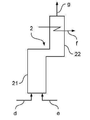
도 2는 단순화된 개략도로 종래 기술에 따른 연소된 반응기를 도시하며, 반응기는 일반적으로 2로 표시된다. 전술한 바와 같이, 이러한 종류의 연소된 반응기는 일반적으로 스팀 크래킹에 의해 탄화수소 또는 합성가스를 생성하는데 사용될 수 있다. 대응하는 반응기 (2)는 일반적으로 공지된 바와 같이, 전형적으로 복사 영역 (21) 및 대류 영역 (22)을 포함한다. 복사 영역 (21)에서, 일반적으로 연료 (d)가 공급되는 다수의 버너가 배열된다(도시되지 않음). 연소는 연소지지 가스(e)의 공급에 의해 가능해진다. 복사 영역 (21) 및 대류 영역 (22)에는 일반적으로 상응하는 버너에 의해 외부로부터 가열되는 반응 튜브가 있다.Figure 2 shows a burned reactor according to the prior art in a simplified schematic, the reactor being generally indicated at 2; As described above, this type of combusted reactor can generally be used to produce hydrocarbons or syngas by steam cracking. The
연소된 반응기 (2)에서, 폐열은 대부분 가압 증기 (f)를 생성하기 위해 사용되지만, 후자는 일반적으로 전기 에너지의 생성을 위해 만족할만한 정도의 효율로 사용되기에 비교적 부적합하다. 도 2에 도시된 바와 같은 일반적인 연소된 반응기 (2)로부터 나온 가압 증기 (f)의 더 낮은 이용가치는 비교적 낮은 온도와 비교적 낮은 압력 및 단지 하나의 스팀 레벨이 실현된다는 사실에서 기인한다 (따라서 스팀 발생 동안 비교적 큰 엑서지 손실). 일반적인 가스 및 증기 발전소, 예를 들어 도 1에 도시된 가스 및 증기 발전소 (300)에서 가압 증기 (f)는 1bar 및 750 ℃에서 얻어지는 반면, 도 2의 연소된 반응기 (2)에서 나온 가압 증기 (f)의 압력은 일반적으로 단지 1bar이고 온도는 일반적으로 단지 5 ℃이다. 일반적으로, 가열된 반응기 (2)로부터 나온 상응하는 가압 증기 (f)는 (예를 들어 스팀 크래킹 장치에서) 샤프트 동력을 회수하는 데 사용되며 가열 증기로서 사용된다. 여기서도 냉각된 연소 배기 가스 (g)가 얻어진다.In the burned
상응하는 에너지 균형 고려에서, 연료 (d)의 형태로 약 1,000 MW의 언더파이어 전력 (일반적으로 다수의 반응기에 걸쳐 분포)을 가정하고, 예를 들어 복사 영역 (21)에서 약 0.42 (스팀 크래킹 공정에 사용되는 반응기에 대한 일반적인 값)의 일반적인 복사 영역 효율로 연소지지 가스 (e)로서 약 1,067,000 N㎥/h의 연소 공기 공급을 가정하면, 반응기 (2)에서 나온 폐열로부터 약 512 MW 또는 약 595 t/h의 감압 증기 (f)가 얻어질 수 있다. 대략 60 MW가 냉각된 연소 배기 가스 (g)로 들어가고, 이는 약 1,172,000 N㎥/h의 양에서 또한 약 128 ℃의 온도에서 제거된다. "누락된" 428 MW의 열전력은 화학 결합 에너지의 형태로 및 튜브-사이드 공정 가스, 즉 연도 가스 스트림에서가 아니라 반응기 (2)의 반응 영역으로부터 현열 형태로 방출된다. 이 값은 동일한 양의 반응 생성물이 생성됨에 따라 여기서 예시로 제공된 다음 도면의 모든 반응기 (2)에 대해서 동일하다.Assuming a corresponding energy balance, assuming an under fire power of approximately 1,000 MW in the form of fuel (d) (generally distributed over a large number of reactors), for example, about 0.42 in the
도 3은 가스 터빈 (1) 및 종래 기술에 따른 가열된 반응기 (2)가 결합된 설비의 단순화된 개략도이며, 전체적으로 400으로 표시되었다. 이러한 설비 (400)를 제공의 기본적인 아이디어는 가스 및 증기 발전소, 예를 들어 상응하는 가열된 반응기 (2)에서의 도 1에 표시된 가스 및 증기 발전소 (300)와 유사하게 가스 터빈 (1)으로부터 나온 연소 배기 가스 (c)의 현열을 사용하는 것이다. 이는 전술한 사실, 가스 터빈 (1)에서 상당한 화학양론적 연소의 결과로 연소 배기 가스 (c)가 여전히 상당한 산소 함량을 갖는다는 사실을 이용한다. Figure 3 is a simplified schematic diagram of a combined equipment of a
그럼에도 불구하고, 추가적인 연소지지 가스 (d), 예를 들어 공기가 도시된 실시예에서 공급된다(예를 들어 연소 배기 가스 (c) 가 송풍기 (3)에 의해 공급됨).Nevertheless, additional combustion supporting gas (d), for example air, is supplied in the illustrated embodiment (e.g., the combustion exhaust gas (c) is supplied by the blower 3).
이러한 추가 공급은 반응기 (2)에서의 연소를 조절하기 위한 추가적인 조절 변수를 제공하는 역할을 한다.This additional feed serves to provide additional control parameters for controlling combustion in the
그러나, 종래 기술에 따른 이러한 종류의 조합 설비 (400)의 중요한 단점은, 복사 영역 (21)에서 연소된 반응기 (2)의 복사 영역 효율이 현저히 감소한다는 것이다. 예를 들어, 도 2에 도시된 바와 같이 자기 유지형 반응기 (2)와 비교하여, 복사 영역 효율은 예를 들어 약 0.42에서 약 0.37로 감소한다. 이것은 연소 배기 가스 (c)가 비교적 고온, 예를 들어 약 600 ℃의 비교적 고온을 가짐에도 불구하고, 그 산소 함량(예를 들어 약 14 %의 산소 함량)이 일반적으로 사용되는 연소 공기와 같은 연소지지 가스의 산소 함량보다 현저히 낮다는 사실에 특히 부과될 수 있다. 이는 추가적인 연소 공기 (d) 또는 상응하는 연소지지 가스 (적어도 유난히 고가의 산소 농축이 없는 경우)의 공급에 의해 보상될 수 없다. 만약 도 2에 도시된 바와 같이 자가 유지 방식으로 작동하는 반응기 (2)에서 약 21 %의 산소를 함유하는 공기가 연소지지 가스 (d)로 사용되는 경우라면, 약 2,000 ℃의 단열 연소 온도는 반응기 (2)의 복사 영역 (21)에서 연소에 의해 여전히 달성될 수 있다. 대조적으로, 도 3에 도시된 바와 같은 설비 (400)에서, 복사 영역 (21)에서의 단열 연소 온도는 상술한 상황으로 인해 약 1,750 ℃로 제한된다. 이는 언급한 더 낮은 복사 영역 효율에 직접적으로 반영된다.However, a significant disadvantage of this type of
에너지 균형의 관점에서 볼 때, 연소지지 가스 (a)에 함유된 화학 에너지의 상당 부분은 가스 터빈 (1)에서 제거되고, 따라서 연소 배기 가스 (c)에서 더 이상 사용 불가능하다.In view of the energy balance, a significant portion of the chemical energy contained in the combustion supporting gas (a) is removed from the
실시예 데이터는 이제 최대화된 가스 터빈 동력, 즉 조절을 위한 추가적인 연소지지 가스 (d)의 최소 사용으로 1,000 MW의 출력에서 스팀 그래킹 작동을 위한 하나 이상의 반응기의 가스 터빈 상류에 제공된다. 이러한 설비 (400)에서 예를 들어 약 1,132,000 N㎥/h의 연소 공기가 연소지지 가스 (a)로 사용되고, 만약 약 3 MW의 언더파이어 전력이 연료 (b)의 형태로 사용된다면 이전에 설명된 효율 레벨에서 가스 터빈 (1)에 연결된 발전기 (G)에서 약 118 MW의 전력을 얻을 수 있다. 약 224 MW가 연소 배기 가스 (c)에 현열로 통과한다. 특히 발전기 (G)와 보조 장비에서 및 가스 터빈 (1)의 오일 쿨러에서 약 5 MW의 손실이 지속된다. 연소 배기 가스 (c)는 약 1,170,000 N㎥/h의 양으로 형성된다.The embodiment data is now provided upstream of the gas turbine of one or more reactors for steam-gassing operation at an output of 1,000 MW with a minimum use of the maximized gas turbine power, i. E. Additional combustion support gas (d) for conditioning. In this
도시된 실시예에서, 예를 들어 약 189,000 N㎥/h의 연소 공기가 연소지지 가스 (d)로 사용된다. 연료 (e) 형태에서 언더파이어 전력은 약 922 MW이다. 따라서, 사용된 연료 (b) 및 (e) 형태에서 총 열전력은 약 1,270 MW, 연소 배기 가스 (c)의 현열로부터 및 연료 (e)의 형태에서 언더파이어 전력으로부터 얻을 수 있는 복사 영역 (21)에서 이용 가능한 열전력은 약 1,147 MW이다. 이들 중 약 650 MW가 가압 증기 (f)의 형태로 약 756 t/h의 양으로 회수되며, 약 69 MW가 이전과 같이 약 128 ℃에서 제거되는 냉각된 연도 가스 (g)로 이동한다. 냉각된 연도 가스 (g)의 양은 도 2에 도시된 바와 같이 자기 유지형 반응기 (2)에서 전술한 약 1,172,000 N㎥/h와 비교하여 약 1,457,000 N㎥/h이다. 여기에서도 도 2에 따른 반응기 (2)에서와 같이 동일한 양의 반응 생성물이 생성되므로, 튜브-사이드 공정 가스에서 화학 결합 에너지 및 현열로 428 MW가 방출된다.In the illustrated embodiment, for example, about 189,000 Nm3 / h of combustion air is used as the combustion supporting gas (d). In the form of fuel (e), under fire power is about 922 MW. The total thermal power in the form of the fuel b and e used is therefore about 1,270 MW and the
이미 언급한 바와 같이, 복사 영역 (21)에서의 복사 영역 효율은 약 0.37로 감소된다. (가압 증기 (f)로부터의) 증기 발생의 효율 레벨은 약 0.51이고, 전체 열효율은 약 0.94이다. (복사 영역 (21)에서 공정 가스로 들어가는 열의 일부는 증기 발생을 위해 사용된다. 그러므로 두 효율 레벨을 함께 더해서는 안되고, 특정 열효율을 얻기 위해 서로 보완할 필요가 없다. 공정 가스와 함께 배출되는 열 및 화학 결합 에너지의 양은 전체 에너지 균형에 존재하지 않는다. 그러나, 이들 값은 또한 첨부된 도면에 도시된 모든 반응기 (2)에서 동일하다.)As already mentioned, the radiation area efficiency in the
도 4는 본 발명의 일 실시예에 따른 가스 터빈 (1) 및 연소된 반응기 (2)를 갖는 결합된 장치를 간략화된 개략도로 도시하며, 상기 장치는 일반적으로 100으로 표시되어있다.Figure 4 shows a simplified schematic of a combined apparatus having a
전술한 바와 같이, 본 발명의 주요 측면은 반응기 (2)에서 공급되는 연소지지 가스 (b)가 예열되는 예열기 (4)의 사용이다. 도 4에 도시된 실시예에서, 가스 터빈 (1)으로부터 나온 모든 연소 배기 가스 (c)는 예열기 (4)를 통과하지만, 연소 배기 가스 (c)의 일부만을 사용할 수도 있다. 후자는 첨부된 도 5에 도시되어있다. 예를 들어, 하나 이상의 적합하게 구성된 열교환기를 포함할 수 있는 예열기 (4)에 의해, 연소 배기 가스 (c)의 현열이 연소지지 가스 (d)로 전달될 수 있다.As described above, the main aspect of the present invention is the use of the
이것은 여전히 높은 산소 함량을 갖는 연소 공기와 같은 연소지지 가스 (d)가 반응기 (2)로 공급될 수 있지만, 동시에 연소 배기 가스 (c)의 현열로 가열될 수 있다는 특별한 이점을 갖는다. 알 수 있듯이 놀랍게도, 이는 도 3에 도시된 대응하는 결합 설비 (400)의 반응기와 비교할 때 뿐만 아니라 도 2에 도시된 자기 유지형 반응기 (2)와 비교할 때, 복사 영역 (21)에서 복사 영역 효율이 상당히 증가한다. 경험칙으로 보건데, 10 ℃의 예열은 복사 영역 효율에 0.2 %의 증가를 가져온다.This has the particular advantage that the combustion supporting gas d such as combustion air still having a high oxygen content can be supplied to the
도 4에 도시된 장치 (100)에서, 복사 영역에서 약 0.47의 복사 영역 효율 레벨이 얻어진다. 약 383,000 N㎥/h의 연소 공기가 연소지지 기체 (a)로 사용되고, 약 108 MW의 언더파이어 전력이 스트림 (b)의 형태로 사용되는 경우, 가스 터빈 (1) 또는 상응하는 발생기 (G)로 약 40 MW의 전력이 얻어질 수 있다. 연소 배기 가스 (c)는 약 76 MW의 현열에 상응하는 약 656 ℃(이는 예시로 주어진 값이며, 일반적인 값은 550 - 700 ℃)이다. 예열기 (4)의 하류에서 연소 배기 가스 (c)의 온도는 여전히 약 10 MW의 현열에 상응하는 약 105 ℃이다.In the
냉각된 연소 배기 가스의 온도 (연도 가스 온도)는 일반적으로 소위 "황 이슬점"에 의해 결정된다. 이 온도에서 황산 수용액이 응축되어 심각한 부식을 일으킨다. 황 이슬점은 람다값 1.1에서(스팀 크래킹 반응기에서) 보다 람다값 3에서(가스 터빈의 연도 가스에서와 같이) 현저히 낮은데, 왜냐하면 비례적으로 더 적은 양의 (일반적으로 황-함유)연료 또는 연소 생성물이 존재하기 때문이다. 일반적인 가열 가스에 대한 예시 값은 한편으로는 105 ℃이고, 다른 한편으로는 128 ℃이다.The temperature of the cooled combustion exhaust gas (flue gas temperature) is generally determined by the so-called "sulfur dew point ". At this temperature, the aqueous sulfuric acid condenses and causes severe corrosion. The sulfur dew point is significantly lower at a lambda value of 3 (as in the flue gas of a gas turbine) than at a lambda value of 1.1 (in a steam cracking reactor) because a proportionally smaller amount of (generally sulfur-containing) fuel or combustion products Because it exists. An exemplary value for a common heating gas is 105 ° C on the one hand and 128 ° C on the other hand.
연소 배기 가스 (c)의 양은 대략 395,000 N㎥/h이다. 이 외에도, 예를 들어 약 28℃에서 스트림 (d) 형태로 약 879,000 N㎥/h의 연소 공기가 연소지지 가스로서 공급되고, 이는 예열기 (4)에서 약 286 ℃로서, 약 66 MW의 현열에 상응하며, 연료 (e) 형태로 언더파이어 전력이 약 824 MW이면 총 이용 가능한 열전력은 약 942 MW이고 반응기 (2)에서 이용 가능한 열전력은 약 890 MW이다. 이들 약 890 MW 중, 약 462 MW의 잔류가 약 0.47의 복사 영역 효율에서 생성되고, 그 중 약 408 MW가 약 475 t/h에서 가압 증기 (f)의 형태로 얻어지며, 그 중 약 54 MW는 약 128 ℃ 또는 약 966,000 N㎥/h 에서 냉각된 연도 가스 (g)의 형태로 얻어진다.The amount of combustion exhaust gas (c) is approximately 395,000
상응하는 장치 (100)에서, 연소지지 가스 (d)는 표 (하기 참조)에 기재되어 있듯이, 도시된 것처럼 상당히 높은 온도로 예열될 수 있다.In the
도 5는 본 발명의 또 다른 실시예에 따른 가스 터빈 (1) 및 연소된 반응기 (2) 결합 장치를 단순화된 개략도로 도시하며, 이 장치는 일반적으로 200으로 지정된다. 상기 장치 (200)는 도 4에 도시된 장치 (100)와는 달리 연소 배기 가스 (c) 스트림의 일부만이 예열기 (4)를 통과한다는 점이 다르다. 이 부분 스트림은 장치 (200)에서 (c')로 표시된다. 여기에서 (c")로 표시된 또 다른 부분 스트림은 연소지지 가스 (d)와 결합된다. 이는 특히 설비 (200)의 유연한 작동을 초래하거나, 설명된 것처럼 반응기 (2)의 작동 조건은 도 2에 도시된 바와 같이 자기 유지형 반응기 (2)의 작동 조건에 근사될 수 있다.5 shows a simplified schematic diagram of a
도 5 또는 설비 (200)에 따른 본 발명의 상응하는 실시예는, 특히, 연소 배기 가스 (c)에서 각 열 공급 및/또는 반응기 (2)에서 열 요구량에 대한 적응을 가능하게 하기 위해 부분 스트림 (c') 및 (c")를 조절 가능한 양으로 제공하는 단계를 포함할 수 있다. 다시 한번, 설비 (200)에 대한 특성 값의 예가 아래에 제공된다.The corresponding embodiment of the invention according to Fig. 5 or
연소 공기가 설비 (200)에서 약 1,035,000 N㎥/h의 양의 연소지지 가스 (a)로서 제공되고, 만약 약 318 MW의 연료 (d) 형태로 언더파이어 전력이 사용되는 경우, 약 107.8 MW의 전력이 가스 터빈 (1)에서 약 0.34의 효율 레벨로 생성될 수 있다. 해당 설비의 전기 효율은 직접적인 발전소의 가스 터빈 보다 다소 낮으며(비교. 도 1과 관련된 설명 : 효율 레벨 0.36), 추가적으로 반응기 (2)를 통한 압력 손실이 극복되어야 한다.Combustion air is provided as a combustion support gas (a) in an amount of about 1,035,000 Nm3 / h in the
연소 배기 가스 (c)에서 전체적으로 약 211 MW에 대항하는 현열이 남아있다. 약 77 MW의 열량에 상응하는 부분 스트림 (c')이 제공되면, 이 부분 스트림 (c')에 의해 약 67 MW에 해당하는 현열이 연소 공기 (이 경우에는 연소지지 가스 (d)로 사용됨)로 예열기 (4)에서 전달될 수 있다. 예열기 (4)의 하류 측에서, 약 656 ℃ 에서 105 ℃로 온도가 감소하는 것에 대응하여, 시간당 약 391,000 N㎥/h의 양으로 제공되는 상기 스트림 (c')에 약 10 MW의 현열이 남아있다(황 이슬점에 관한 도 4의 설명을 참조).There is still sensible heat in the combustion exhaust gas (c) as a whole against about 211 MW. If a partial stream c 'corresponding to a calorific value of about 77 MW is provided, sensible heat corresponding to about 67 MW by this partial stream c' is used as combustion air (in this case used as combustion support gas d) In the preheater (4). On the downstream side of the
이미 언급한 바와 같이, 예를 들어 연소 공기는 가스 (d)에 연소 지지체로서 송풍기 (3)에 의해 제공되고, 약 28 ℃의 온도 (일례로서, 주위 온도)에 있다. 연소 공기의 양은 예를 들면, 약 397,000 N㎥/h이다. 예열기 (4)에서 연소 공기는 상기 스트림 (c')로부터 약 67 MW에 상응하는 약 627 ℃로 가열된다. 연소 배기 가스 (c)의 부분 스트림 (c")는 약 67 MW의 현열에 상응하는 약 679,000 N㎥/h의 양으로 공급된다. 또한, 약 799 MW에 해당하는 연료 (e)가 반응기 (2)에 공급된다.As already mentioned, for example, the combustion air is provided by the
그러므로, 전체적으로 약 1,000 MW의 열전력이 반응기 (2)에서 이용 가능하고, 전체적으로 약 1,118 MW의 열전력이 설비 (200)에서 이용 가능하다. 스트림 (c') 및 (c")의 적절한 조정에 의해, 도 2에 도시된 바와 같이 자기 유지형 반응기 (2)의 복사 영역과 정확하게 상응하는 반응기 (2)의 복사 영역 (21)에서 약 0.42의 복사 영역 효율이 달성될 수 있다. 512 MW는 약 595 t/h로 제공되는 가압 증기 (f)에 잔류하고, 약 60 MW는 냉각된 연소 배기 가스 (c) 내에 잔류하며 그 중 약 1,172,000 N㎥/h가 128 ℃에서 제공된다.Therefore, an overall thermal power of about 1,000 MW is available in the
다음의 표 1 내지 5에서, 도 1 내지 도 5와 관련하여 전술한 유량 및 에너지양이 다시 도시되며, 여기서 도 4 또는 장치 (100)에 도시된 바와 같이 표 4a 및 4b는 두 가지 작동 케이스, 즉 연소지지 가스 (d)의 286 ℃로의 예열(종래 공정 제어가 반응기 (2)에서 일어날 수 있는 경우; 상기 참조), 498 ℃로의 예열 (공급물의 부분 과열 또는 외부/간접 예열만으로 증기 발생과 같은 추가 공정 변화가 반응기 (2)에 필요한 경우)의 경우를 나타낸다. 모든 경우에, 연소지지 가스 (a) 또는 (d)로서 공기가 사용되고, 연료로 (잔류) 가스가 사용된다. 지정된 값은 반올림 오류를 무시하고 대략적인 값으로 이해되어야 한다. 연소 배기 가스 (c) 및 냉각된 연소 배기 가스 (g)의 열전력은 현열에 상응하고, 가압 증기 (f)의 열전력은 현열 및 증발 엔탈피의 합에 상응한다.In the following Tables 1 to 5, the flow and energy amounts described above with reference to Figures 1 to 5 are again shown wherein Tables 4a and 4b, as shown in Figure 4 or
다음의 표 6a 내지 6c는 본 발명의 장점을 서로 보여주기 위한 비교 가능한 공정을 나타낸다. 모든 표에서 동일한 양의 전류(표에서 "전류 생산" 행)가 설비 전체에서 생성되어야 하며, 동일한 양의 반응 생성물(이 경우 탄화수소 에틸렌, 표에서 "에틸렌 생산" 행)이 반응기 (2)에서 생산되어야 한다. 위의 도면과 특히 도면 설명의 소개 단락을 명백히 참조할 수 있다.The following Tables 6a to 6c show comparable processes for showing the advantages of the present invention to each other. The same amount of current (in the table, "current production" row) must be generated throughout the plant in all tables and the same amount of reaction product (in this case ethylene ethylene, row "ethylene production" . It is expressly referred to the above figures and particularly the introductory paragraphs of the drawings.
또한 전류가 가압 증기 (f)로 생성된다고 가정한다. 이것은 주로 전기 효율 측면 및 위의 정의에서 "효율(efficiency)" 측면에서 공정의 비교 가능성을 향상시키는데 크게 기여한다. 표의 "전류 생산" 행 또는 이에 주어진 값은 520 ℃ 및 120 bar에서 가압 증기 (f)에 대한 0.24의 일반적인 전기 효율을 가정하여 가압 증기 (f)로부터 생산된 전류를 포함한다.It is also assumed that the electric current is generated by the pressurized steam (f). This largely contributes to improving the comparability of the process in terms of "efficiency" in terms of electrical efficiency and the definition above. The "current production" row or the value given in the table includes the current produced from pressurized steam (f) assuming a general electric efficiency of 0.24 for pressurized steam (f) at 520 ° C and 120 bar.
표의 1 열 ("반응기, 주 전류")은 도 2에 따라 주전원에 의해 공급된 전류 및 자기 유지형 방식으로 작동되는 반응기 (2)에 대한 값을 포함한다. 주전원에서 공급되는 전류의 생산을 위해, 0.33의 효율이 가정된다. 이는 기존의 주전원에 대한 일반적인 평가치와 상응한다(즉, 모든 종류의 구 및 신 발전소, 즉 순수 (석탄) 증기 발전소와 가스 및 증기 발전소를 포함하는 공급기로부터 발전소의 네트워크에 걸친 및 모든 라인의 손실을 포함하는 평균 전기 효율). 따라서 가압 증기 (f)로부터 전류가 발생하지 않는다면, 1 열에 따라 주전원에서 전류가 공급된다.
주전원으로부터 공급되는 이 비율의 전류를 생성하는 데 필요한 0.33의 효율 수준에 해당하는 화력은 반응기 (2)가 공정을 비교할 수 있게 하기 위한 열전력 외에 필요한 총 열전력(표에서 "총 열전력" 행)에 포함된다. 이 열전력은 표의 2 열 (표의 "열전력 %" 행)에서 특정된 열전력에 표준화된 열전력으로서 추가적으로 주어진다.The thermal power corresponding to an efficiency level of 0.33 required to produce this percentage of the current supplied from the mains is the sum of the total thermal power required by the
표의 2 열 ("반응기, 가스 및 증기 발전소")은 예를 들어 도 1에 따라 별도의 가스 및 증기 발전소의 조합에 대한 값을 제공하며, 예를 들어 표의 1 열에 이미 특정된 대로 도 2에 따른 자기 유지형 반응기 (2)의 값을 제공합니다. 가스 및 증기 발전소의 전류 생산에 필요한 열전력은 여기에서 가정한 0.56의 전체 전기 효율 (도 1에 따른 설명 참조)에 따라 달라지며, 상기 언급된 표의 행에 언급된 총 열전력에 포함된다(반응기 (2)에 대한 열전력에 추가하여).The two columns of the table ("Reactor, Gas and Steam Generator") provide values for a combination of separate gas and steam power plants, for example according to FIG. 1, for example as shown in Table 1, Provide the value of a self-sustaining reactor (2). The thermal power required for the current production of the gas and steam power plants depends on the total electric efficiency of 0.56 here (see the description according to FIG. 1) assumed here and is included in the total thermal power mentioned in the row of the above mentioned table (In addition to the thermal power for (2)).
1 열과 2 열을 함께 보면, 주전원(표에서 1 열)에서 얻거나 가스 및 증기 발전소(표에서 2 열)에서 생성된 전류와 반응 생성물인 에틸렌의 동일한 생산량을 포함하는 동일한 전력 생산(표에서 "전류 생산" 행)에 대해, 요구되는 열전력 감소는 표의 2 열에 따른 상이한 전기 효율(가스 및 증기 발전소의 전류 생산에서 전체 전기 효율 0.56, 도 1의 설명 참조; 일반적인 주 전류는 0.33, 상기 참조)에 기초하여 즉시 달성될 수 있다.Together,
따라서 동일한 양의 반응 생성물인 에틸렌 (표에서 "비 에너지 소비량(specific energy consumption)" 행)에 기초한 공정의 비 에너지 소비는 감소되어, 그에 따라 전술한 의미에서의 공정 "에너지 효율"이 증가된다. 반응기 (2)가 자체적으로 충분히 작동하기 때문에, 반응기 (2)와 관련된 효율 레벨은 변하지 않는다.Thus, the specific energy consumption of the process based on the same amount of reaction product ethylene (the "specific energy consumption" row in the table) is reduced, thereby increasing the process "energy efficiency" in the sense described above. Since the
표 6a에서 상기 설명된 표의 제 1열 및 2열의 값은, 가정된 152 MW의 총 전류 생산에서 도 3에 따른 조합 설비 (400)과 관련된 값과 제 3열("도 3에 따른 조합 설비 (400)")에서 비교된다. 이 152 MW 중, 표의 3열에 따라 118 MW가 가스 터빈 (1)에 의해 생성되고, 34 MW는 상응하는 (낮은) 효율에서 가압 증기 (f)로부터 생성되는 것으로 가정된다(이 단순화는 비교 목적을 위한 것으로, 실제로 가압 증기 (f)의 사용이 전형적으로 압축기 또는 펌프를 구동시키는 샤프트 동력의 직접적 사용인 경우 - 어떤 경우에는 발전기에서 일반적으로 약 1 %의 한계 손실을 제외하고는 전력에 상응한다).The values in the first and second columns of the table described above in Table 6a are the values associated with the
이러한 이유로 표의 3 열에 따른 열전력은 모두 1,270 MW이며, 표의 1 열에 비해 현저한 개선을 나타내지만, 표의 2 열보다 0.1 %의 한계 개선만을 나타낸다.For this reason, the thermal power according to
주 전류Main current
가스 및 증기 발전소Gas and steam power plants
전기 에너지를 생산하기 위한 연료 소비는 결합 생산에서 가능한 전력에 대해 열 1 및 열 2에 따라 2 가지의 벤치마크 케이스(즉, 전류와 반응 생성물의 분리 생산 및 자체 유지형 생산)에서 결정된다. 따라서 벤치마크 케이스는 80 MW 이하의 전력을 가진 가스 및 증기 발전소가 독립적인 발전소로 설립될 가능성이 거의 없음에도 불구하고 "적용"된다. 이는 다음 표에도 적용된다. 가열 요구량이 전체 에너지 소비량의 반 이상을 차지하기 때문에, 열전력 및 비 에너지 소비량은 서로 관련이 있다.Fuel consumption to produce electrical energy is determined in two benchmark cases (ie, separate production of current and reaction products and self-sustaining production) according to
표 6b에서, 표 6a와 관련하여 이미 기재되어 있고 표 6a에서와 동일한 의미를 갖는 제 1 열 및 2 열의 값은, 도 3에 따른 조합 설비 (200)와 관련된 가정된 108 MW의 전류 생산 값과 3 열("도 5에 따른 조합 설비")에서 비교된다. 이것은 반응기 (2)에서의 증기 생성이 자체 유지 반응기에서의 증기 생성과 동일하기 때문에 가스 터빈 (1)의 전류 생산이다.In Table 6b, the values of the first column and the second column, which have already been described in connection with Table 6a and have the same meaning as in Table 6a, are the assumed 108 MW current production values associated with the
도 5에 따른 조합된 설비 (200)에서 부분 스트림 (c') 및 (c")에 대한 연소 배기 가스 (c)의 분배 및 예열기 (4)에서의 예열만을 위한 부분적인 사용 및 반응기 (2)로의 부분 공급으로 인해, 복사 영역 효율은 여기에서 상기 표의 제 1 열 및 제 2 열과 비교하여, 즉 전술한 약 0.42의 값으로 일정하게 유지될 수 있다. 따라서 주어진 변수의 특정 조합으로, 요구되는 열전력은 표의 2 열과 비교하여 약 6%, 표의 1 열과 비교하여 약 17 %로 상당히 감소된다. 동일한 양의 에틸렌 반응 생성물을 기준으로 한 비 에너지 소비량 또한 이에 따라 현저히 감소한다. 동시에, 전술한 바와 같이, 상응하는 반응기 (2)는 종래의 조건 하에서 계속 작동될 수 있다.Partial use only for preheating in the
주 전류Main current
가스 및 증기 발전소Gas and steam power plants
표 6c에서, 표의 제 1 열 및 2 열의 값은, 연소지지 기체 (d)를 498 ℃로 예열(즉, 표 4b에 따라)하고, 가스 터빈에 의한 60 MW의 전류 생산이 가정된 도 4에 따른 조합 설비 (100)와 관련된 값과 3 열(도 4 에 따른 조합 설비, 498 ℃)에서 비교된다. 이 60 MW 중, 43 MW는 증기 생산량이 적어지기 때문에 제거되어야 하며(표에서 "전력에 따른 증기 생산 감소" 행), 그에 상응하는 샤프트 전력의 부족분은 단순히 전력으로 보상된다. 일반적으로 사용되는 전기 엔진의 약 3 % 손실은 간편함을 위해 무시된다.In Table 6c, the values in the first and second columns of the table indicate that the combustion supporting gas (d) is preheated to 498 占 폚 (ie according to Table 4b), and in FIG. 4 where a current production of 60 MW by the gas turbine is assumed And the values associated with the
다시 한번 현저히 증가된 복사 영역 효율, 즉 약 0.53의 값으로 인해, 표의 제 1 열 및 2 열에 비해 전력 생산은 동일하지만 열전력의 상당한 감소가 있다.Again, due to the significantly increased radiated area efficiency, ie, a value of about 0.53, there is a significant reduction in thermal power, although the power production is the same as in the first and second columns of the table.
주 전류Main current
가스 및 증기 발전소Gas and steam power plants
상기 표를 조합한 연구는 특히, (고급) 연료, 예를 들어 반응기 (2)를 사용하여 수행된 상응하는 공정으로 부터의 잔류 가스로부터의 부분 발전은, 도 1에 따른 가스 및 증기 발전소인지 또는 도 3에 따른 설비 (400)의 형태로 공지된 조합이 사용되는지 여부에 관계없이, 일반적인 발전소 혼합을 이용한 전류의 생산 또는 주전원으로부터 가져오는 전류의 생산과 비교하여 약 11%의 효율 증가를 달성한다. 예를 들어, 여기서 전제조건은 특히 적합한 잔류 가스의 충분한 이용이다. 게다가, 도 3에 따른 설비 (400) 형태의 공지된 조합은 전류 및 반응 생성물의 분리 생산에 비해 효율 이점이 없거나 단지 약간만 있는 것으로 나타났다. 즉, 상기 도시된 예에서, 동일한 열전력과 그에 상응하는 연료 공급이 요구된다.The combination of the above table shows that the partial evolution from the residual gas, especially from the corresponding process carried out using (advanced) fuel, for
본 발명의 일 실시예에 따라 제안된 설비 (200)는 가스 및 증기 발전소에 의한 분리된 전류 생산 및 자기 유지형 반응기 (2)에서의 반응 생성물의 분리 제조와 비교하여 약 6 % 더 높은 효율을 가진다. 일반적인 발전소 혼합 또는 주전원에서 전류를 가져오는 것과, 자기 유지형 반응기 (2)의 분리 생산을 비교하면, 약 11 %의 효율 증가가 관찰된다.The proposed
설비 (200)는 사용되는 화력의 추가 단위 당 92 %의 전류를 생성한다 (즉, 자기 유지형 반응기 작동에 필요한 열전력에 추가하여 1 MW의 열전력 당 0.92 MW의 전류가 생성된다). 이것은 가스 및 증기 발전소의 전기 효율을 실질적으로 두 배로 높이는 것에 해당하거나, 발전소 혼합 또는 주전원에서 전류를 취하는 것 전기 효율의 세배에 해당한다.The
제안된 장치 (100)는 자기 유지형 반응기보다 적은 열전력을 필요로 하며, 또한 추가 전류를 생성한다. 따라서, 설비 (100)는 가스 및 증기 발전소에 의한 별도의 전류 발생 및 자기 유지 반응기 (2)에서의 반응 생성물 분리 제조와 비교하여 약 11 % 더 좋은 효율을 갖는다.The proposed
1 : 가스 터빈
2 : 반응기
3 : 송풍기
4 : 예열기
5 : 열 회수 증기 발생기
6 : 감압 터빈
7 : 냉각기
11 : 압축 단
12 : 팽창 단
21 : 복사 영역
22 : 대류 영역
100 : 가스 터빈 및 연소된 반응기가 결합된 설비
200 : 가스 터빈 및 연소된 반응기가 결합된 설비
300 : 가스 및 증기 발전소
400 : 가스 터빈 및 연소된 반응기가 결합된 설비1: Gas Turbine
2: Reactor
3: blower
4: Preheater
5: Heat recovery steam generator
6: Decompression turbine
7: Cooler
11: compression stage
12: Expansion stage
21: Copy area
22: convection region
100: Combined gas turbine and fired reactor
200: Combined gas turbine and fired reactor
300: Gas and steam power plants
400: Combined gas turbine and fired reactor
Claims (15)
상기 기계 동력을 발생시키기 위해 적어도 하나의 내연 기관이 작동되어 연소 배기 가스를 생성하고,
상기 탄화수소를 생산하기 위해 적어도 하나의 반응기가 연료 및 연소지지 가스를 사용하여 가열되며,
상기 내연 기관으로부터 나온 연소 배기 가스의 적어도 일부와 간접적인 열교환에 의해 연소지지 가스의 적어도 일부가 가열되는 것을 특징으로 하는 공정.
In processes combining mechanical power generation and hydrocarbon production,
At least one internal combustion engine is operated to generate the mechanical power to generate combustion exhaust gas,
At least one reactor is heated using fuel and combustion supporting gas to produce the hydrocarbon,
Wherein at least a portion of the combustion supporting gas is heated by indirect heat exchange with at least a portion of the combustion exhaust gas from the internal combustion engine.
상기 기계 동력은 적어도 하나의 발전기에 의해 적어도 부분적으로 전력으로 변환 및/또는 적어도 하나의 샤프트를 구동하는 데 사용되는 것을 특징으로 하는 공정.
The method according to claim 1,
Wherein the mechanical power is used by at least one generator to convert at least in part to power and / or to drive at least one shaft.
적어도 하나의 반응기가 튜브 반응기로 구성되며,
복사 영역에서 반응 튜브는 연료가 연소되는 버너에 의해 외부로부터 가열되는 것을 특징으로 하는 공정.
3. The method according to claim 1 or 2,
Wherein at least one of the reactors comprises a tube reactor,
Wherein the reaction tube in the radiant region is heated from the outside by a burner in which the fuel is burned.
탄화수소를 생성하기 위해, 공급물이 가압 증기에 의해 상기 튜브 반응기로 구성된 반응기의 상기 반응 튜브를 통해 통과되는 것을 특징으로 하는 공정.
The method of claim 3,
Wherein the feed is passed through the reaction tube of the reactor constituted by the tube reactor by pressurized steam to produce the hydrocarbons.
상기 튜브 반응기로 구성된 상기 반응기의 반응 튜브 내에 촉매가 제공되는 것을 특징으로 하는 공정.
The method according to claim 3 or 4,
Wherein the catalyst is provided in a reaction tube of the reactor comprised of the tube reactor.
상기 연료는 상기 적어도 하나의 반응기로부터 나온 생성물 스트림으로부터 분리되는 가스 혼합물에서 적어도 부분적으로 생성되는 것을 특징으로 하는 공정.
6. The method according to any one of claims 1 to 5,
Wherein the fuel is at least partially produced in a gaseous mixture which is separated from the product stream from the at least one reactor.
상기 적어도 하나의 반응기의 적어도 하나의 영역은 1,500 내지 2,500 ℃의 온도 수준으로 가열되고,
특히 상기 연료 및 상기 연소지지 가스를 사용하여 가열함으로써 상기 적어도 하나의 반응기의 상기 적어도 하나의 영역에서 1,500 내지 2,500 ℃의 온도 수준으로 가열되는 것을 특징으로 하는 공정.
7. The method according to any one of claims 1 to 6,
At least one region of the at least one reactor is heated to a temperature level of 1,500 to 2,500 DEG C,
In particular in the at least one region of the at least one reactor, by heating using the fuel and the combustion supporting gas.
상기 적어도 하나의 내연 기관은 적어도 하나의 가스 터빈을 포함하는 것을 특징으로 하는 공정.
8. The method according to any one of claims 1 to 7,
Wherein said at least one internal combustion engine comprises at least one gas turbine.
상기 내연 기관으로부터 나온 상기 연소 배기 가스는 500 내지 1,000 ℃의 온도 수준, 바람직하게는 600 내지 700℃의 온도 수준 또는 500 내지 650 ℃의 온도 수준에서 제공되는 것을 특징으로 하는 공정.
9. The method according to any one of claims 1 to 8,
Wherein the combustion exhaust gas from the internal combustion engine is provided at a temperature level of from 500 to 1,000 占 폚, preferably at a temperature level of from 600 to 700 占 폚 or at a temperature of from 500 to 650 占 폚.
상기 내연 기관으로부터 나온 상기 연소 배기 가스의 일부는 간접 열교환에 의해 연소지지 가스를 가열하는데 사용되고,
상기 내연 기관으로부터 나온 상기 연소 배기 가스의 일부는 연소지지 가스에 결합되어 함께 상기 적어도 하나의 반응기에 공급되는 것을 특징으로 하는 공정.
10. The method according to any one of claims 1 to 9,
A part of the combustion exhaust gas from the internal combustion engine is used for heating the combustion supporting gas by indirect heat exchange,
Wherein a portion of the combustion exhaust gas from the internal combustion engine is coupled to the combustion support gas and fed to the at least one reactor.
상기 내연 기관으로부터 나온 상기 연소 배기 가스는 전체적으로 간접 열교환에 의해 연소지지 가스를 가열하기 위해 사용되며,
상기 적어도 하나의 반응기에 공급되지 않는 것을 특징으로 하는 공정.
10. The method according to any one of claims 1 to 9,
The combustion exhaust gas from the internal combustion engine as a whole is used for heating the combustion supporting gas by indirect heat exchange,
Is not fed to the at least one reactor.
천연 가스 및/또는 메탄 함유 가스 혼합물, 특히 제 6항에 따라 형성된 가스 혼합물은 연료 및/또는 공기가 연소 보조 가스로 사용되는 것을 특징으로 하는 공정.
12. The method according to any one of claims 1 to 11,
Wherein the natural gas and / or methane-containing gas mixture, in particular the gas mixture formed according to claim 6, is used as fuel and / or air as combustion auxiliary gas.
가압 증기는 적어도 하나의 반응기로부터 나온 폐열로부터 생성되고, 적어도 하나의 샤프트, 특히 발전기의 샤프트를 구동시키는 데 사용되는 것을 특징으로 하는 공정.
13. The method according to any one of claims 1 to 12,
Wherein the pressurized steam is generated from waste heat from at least one of the reactors and is used to drive at least one shaft, particularly a shaft of the generator.
상기 기계 동력을 발생시키기 위해 적어도 하나의 내연 기관이 작동되어 연소 배기 가스를 생성하는 단계를 포함하고,
상기 탄화수소를 생산하기 위해 적어도 하나의 반응기가 연료 및 연소지지 가스를 사용하여 가열될 수 있는 단계를 포함하며,
상기 내연 기관으로부터 나온 연소 배기 가스의 적어도 일부와 간접적인 열교환에 의해 연소지지 가스의 적어도 일부가 가열되는 것을 특징으로 하는 설비.
In equipment for the production of mechanical power and the production of hydrocarbons,
And at least one internal combustion engine is operated to generate combustion exhaust gas to generate the mechanical power,
Wherein at least one reactor can be heated using fuel and a combustion supporting gas to produce the hydrocarbon,
And at least a part of the combustion supporting gas is heated by indirect heat exchange with at least a part of the combustion exhaust gas from the internal combustion engine.
Applications Claiming Priority (3)
| Application Number | Priority Date | Filing Date | Title |
|---|---|---|---|
| EP14183742.7 | 2014-09-05 | ||
| EP14183742.7A EP2993331A1 (en) | 2014-09-05 | 2014-09-05 | Method and assembly for parallel production of mechanical power and the manufacture of reaction products |
| PCT/EP2015/070090 WO2016034647A1 (en) | 2014-09-05 | 2015-09-02 | Method and system for generating a mechanical output and producing reaction products in a parallel manner |
Publications (1)
| Publication Number | Publication Date |
|---|---|
| KR20170048573A true KR20170048573A (en) | 2017-05-08 |
Family
ID=51483346
Family Applications (1)
| Application Number | Title | Priority Date | Filing Date |
|---|---|---|---|
| KR1020177009284A KR20170048573A (en) | 2014-09-05 | 2015-09-02 | Method and system for generating a mechanical output and producing reaction products in a parallel manner |
Country Status (12)
| Country | Link |
|---|---|
| US (1) | US20170306835A1 (en) |
| EP (2) | EP2993331A1 (en) |
| JP (1) | JP2017535706A (en) |
| KR (1) | KR20170048573A (en) |
| CN (1) | CN106660001A (en) |
| AU (1) | AU2015310878A1 (en) |
| BR (1) | BR112017003562A2 (en) |
| CA (1) | CA2958172A1 (en) |
| EA (1) | EA201790308A1 (en) |
| PH (1) | PH12017500249A1 (en) |
| TW (1) | TW201630657A (en) |
| WO (1) | WO2016034647A1 (en) |
Families Citing this family (1)
| Publication number | Priority date | Publication date | Assignee | Title |
|---|---|---|---|---|
| EP3488091A1 (en) | 2016-07-25 | 2019-05-29 | SABIC Global Technologies B.V. | Process for cracking hydrocarbon stream using flue gas from gas turbine |
Family Cites Families (6)
| Publication number | Priority date | Publication date | Assignee | Title |
|---|---|---|---|---|
| FR1445870A (en) * | 1964-08-11 | 1966-07-15 | Chemical Construction Corp | Method and apparatus for reforming hydrocarbons by steam |
| GB8327074D0 (en) * | 1983-10-10 | 1983-11-09 | English Electric Co Ltd | Fluidised-bed heat and power plant |
| GB8526978D0 (en) * | 1985-11-01 | 1985-12-04 | Foster Wheeler Energy Ltd | Chemical process fired heaters &c |
| US5048284A (en) * | 1986-05-27 | 1991-09-17 | Imperial Chemical Industries Plc | Method of operating gas turbines with reformed fuel |
| JP3196549B2 (en) * | 1995-01-09 | 2001-08-06 | 株式会社日立製作所 | Power generation system with fuel reformer |
| JP2006161603A (en) * | 2004-12-03 | 2006-06-22 | Ebara Corp | Gas turbine device and gas turbine power generation system |
-
2014
- 2014-09-05 EP EP14183742.7A patent/EP2993331A1/en not_active Withdrawn
-
2015
- 2015-09-02 BR BR112017003562A patent/BR112017003562A2/en not_active Application Discontinuation
- 2015-09-02 EP EP15760433.1A patent/EP3189223B1/en not_active Not-in-force
- 2015-09-02 JP JP2017512358A patent/JP2017535706A/en active Pending
- 2015-09-02 AU AU2015310878A patent/AU2015310878A1/en not_active Abandoned
- 2015-09-02 CN CN201580047812.4A patent/CN106660001A/en active Pending
- 2015-09-02 EA EA201790308A patent/EA201790308A1/en unknown
- 2015-09-02 US US15/508,575 patent/US20170306835A1/en not_active Abandoned
- 2015-09-02 KR KR1020177009284A patent/KR20170048573A/en unknown
- 2015-09-02 CA CA2958172A patent/CA2958172A1/en not_active Abandoned
- 2015-09-02 WO PCT/EP2015/070090 patent/WO2016034647A1/en active Application Filing
- 2015-09-03 TW TW104129091A patent/TW201630657A/en unknown
-
2017
- 2017-02-09 PH PH12017500249A patent/PH12017500249A1/en unknown
Also Published As
| Publication number | Publication date |
|---|---|
| EP3189223B1 (en) | 2018-06-27 |
| EP2993331A1 (en) | 2016-03-09 |
| JP2017535706A (en) | 2017-11-30 |
| US20170306835A1 (en) | 2017-10-26 |
| WO2016034647A1 (en) | 2016-03-10 |
| AU2015310878A1 (en) | 2017-03-09 |
| PH12017500249A1 (en) | 2017-07-03 |
| EA201790308A1 (en) | 2017-08-31 |
| EP3189223A1 (en) | 2017-07-12 |
| TW201630657A (en) | 2016-09-01 |
| BR112017003562A2 (en) | 2017-12-05 |
| CN106660001A (en) | 2017-05-10 |
| CA2958172A1 (en) | 2016-03-10 |
Similar Documents
| Publication | Publication Date | Title |
|---|---|---|
| CN1024212C (en) | Method and equipment for generating mechanical energy | |
| US4238403A (en) | Methanol synthesis process | |
| CN1295140C (en) | Production enhancement for a reactor | |
| RU2502030C2 (en) | Production of cement clinker and plant to this end | |
| US10190060B2 (en) | Process for increasing process furnaces energy efficiency | |
| JP5183093B2 (en) | A method of co-producing hydrogen-rich gas and electricity by steam reforming hydrocarbon fractions with on-site hydrogen combustion heat supply | |
| EP3730456A1 (en) | Use of renewable energy in ammonia synthesis | |
| JP2002536587A (en) | Power generation method using an improved thermochemical recovery heat exchange cycle | |
| JPS6113448B2 (en) | ||
| JP7408692B2 (en) | Method of driving machinery in an ethylene plant steam generation circuit and integrated ethylene power plant system | |
| US8673034B2 (en) | Methods and systems for integrated boiler feed water heating | |
| KR20230008046A (en) | Ultra-Low Emissions Ethylene Plant | |
| EP1091095B1 (en) | Gas turbine system and combined plant comprising the same | |
| US10465631B2 (en) | System for generating an improved H2:CO ratio in syngas and an associated method thereof | |
| KR20170048573A (en) | Method and system for generating a mechanical output and producing reaction products in a parallel manner | |
| CN103097694A (en) | Generating power using an ion transport membrane | |
| RU2017122296A (en) | METHOD FOR CONVERSION OF NATURAL GAS WITH WATER STEAM, INCLUDING TWO COMBUSTION CHAMBERS, GENERATING HOT SMOKE GASES, TRANSFERRING HEAT ENERGY, PERFORMANT FOR CARRY AND CLEANERS | |
| US20230116003A1 (en) | Methanol production method | |
| JPS61192816A (en) | Compound type power generation system | |
| RU2117627C1 (en) | Method of preparing methanol | |
| RU2804471C2 (en) | Method for powering machines in steam generation circuit of an ethylene producing unit and combined system of an ethylene producing unit and a power plant | |
| US20110296845A1 (en) | Combined heat and power with a peak temperature heat load | |
| RU2774007C1 (en) | Method of contact gas turbine plant operation on methane-hydrogen steam-gas mixture | |
| RU2244133C1 (en) | Method for steam generation at production of ammonia | |
| CN1680767A (en) | Waste heat utilizing loop-closing system of industrial furnace with producer gas as fuel |