KR20170047263A - Sensor arrangement for determining at least one parameter of a fluid medium flowing through a measurement channel - Google Patents
Sensor arrangement for determining at least one parameter of a fluid medium flowing through a measurement channel Download PDFInfo
- Publication number
- KR20170047263A KR20170047263A KR1020177006333A KR20177006333A KR20170047263A KR 20170047263 A KR20170047263 A KR 20170047263A KR 1020177006333 A KR1020177006333 A KR 1020177006333A KR 20177006333 A KR20177006333 A KR 20177006333A KR 20170047263 A KR20170047263 A KR 20170047263A
- Authority
- KR
- South Korea
- Prior art keywords
- sensor
- sensor carrier
- carrier
- measurement channel
- fluid medium
- Prior art date
Links
Images


Classifications
-
- G—PHYSICS
- G01—MEASURING; TESTING
- G01F—MEASURING VOLUME, VOLUME FLOW, MASS FLOW OR LIQUID LEVEL; METERING BY VOLUME
- G01F1/00—Measuring the volume flow or mass flow of fluid or fluent solid material wherein the fluid passes through a meter in a continuous flow
- G01F1/68—Measuring the volume flow or mass flow of fluid or fluent solid material wherein the fluid passes through a meter in a continuous flow by using thermal effects
- G01F1/684—Structural arrangements; Mounting of elements, e.g. in relation to fluid flow
- G01F1/6842—Structural arrangements; Mounting of elements, e.g. in relation to fluid flow with means for influencing the fluid flow
-
- G—PHYSICS
- G01—MEASURING; TESTING
- G01F—MEASURING VOLUME, VOLUME FLOW, MASS FLOW OR LIQUID LEVEL; METERING BY VOLUME
- G01F1/00—Measuring the volume flow or mass flow of fluid or fluent solid material wherein the fluid passes through a meter in a continuous flow
- G01F1/68—Measuring the volume flow or mass flow of fluid or fluent solid material wherein the fluid passes through a meter in a continuous flow by using thermal effects
- G01F1/684—Structural arrangements; Mounting of elements, e.g. in relation to fluid flow
-
- G—PHYSICS
- G01—MEASURING; TESTING
- G01F—MEASURING VOLUME, VOLUME FLOW, MASS FLOW OR LIQUID LEVEL; METERING BY VOLUME
- G01F13/00—Apparatus for measuring by volume and delivering fluids or fluent solid materials, not provided for in the preceding groups
-
- G—PHYSICS
- G01—MEASURING; TESTING
- G01F—MEASURING VOLUME, VOLUME FLOW, MASS FLOW OR LIQUID LEVEL; METERING BY VOLUME
- G01F15/00—Details of, or accessories for, apparatus of groups G01F1/00 - G01F13/00 insofar as such details or appliances are not adapted to particular types of such apparatus
-
- G—PHYSICS
- G01—MEASURING; TESTING
- G01F—MEASURING VOLUME, VOLUME FLOW, MASS FLOW OR LIQUID LEVEL; METERING BY VOLUME
- G01F5/00—Measuring a proportion of the volume flow
Abstract
본 발명은, 측정 채널(28)을 관류하는 유체 매체, 특히 내연기관의 흡입 공기 질량 유량의 적어도 하나의 매개변수를 측정하기 위한 센서 장치(10)에 관한 것이다. 센서 장치(10)는, 센서 하우징(12), 특히 측정 채널(28)이 형성되어 유동 튜브 내로 삽입되거나 삽입될 수 있는 플러그인 센서와, 측정 채널(28) 내에 배치되어 유체 매체의 매개변수를 측정하기 위한 적어도 하나의 센서 칩(42)을 포함한다. 센서 칩(42)은 측정 채널(28) 안쪽으로 돌출되는 센서 캐리어(40) 상에 장착된다. 센서 캐리어(40)는 코드(78)를 포함하도록 형성된다. 코드(78)는 4.5㎜ 내지 6.5㎜의 길이를 갖는다. 한 바람직한 개선예에서 센서 캐리어는 이중 타원형 또는 스프링보드의 형태로 형성된다.The present invention relates to a sensor device (10) for measuring at least one parameter of an intake air mass flow rate of a fluid medium, in particular an internal combustion engine, flowing through a measurement channel (28). The sensor device 10 comprises a sensor housing 12 and in particular a plug-in sensor in which a measurement channel 28 is formed and can be inserted or inserted into the flow tube, And at least one sensor chip (42) The sensor chip 42 is mounted on the sensor carrier 40 protruding into the measurement channel 28. The sensor carrier (40) is formed to include a cord (78). The cord 78 has a length of 4.5 mm to 6.5 mm. In one preferred refinement, the sensor carrier is formed in the form of a double oval or springboard.
Description
본 발명은, 측정 채널을 관류하는 유체 매체, 특히 내연기관의 흡입 공기 질량 유량의 적어도 하나의 매개변수를 측정하기 위한 센서 장치에 관한 것이다.The present invention relates to a sensor device for measuring at least one parameter of an intake air mass flow rate of a fluid medium, in particular an internal combustion engine, flowing through a measurement channel.
종래 기술로부터는 유체 매체, 다시 말하면 액체 및/또는 기체의 유동 특성을 측정하기 위한 수많은 방법 및 장치가 공지되어 있다. 이 경우, 유동 특성들은, 유체 매체의 유동을 정성화하거나 정량화하면서 물리적 및/또는 화학적 측정이 가능한 임의의 특성들일 수 있다. 이는 특히 유동 속도 및/또는 질량 유량 및/또는 체적 유량일 수 있다.Numerous methods and apparatus for measuring the flow characteristics of fluid media, i. E. Liquids and / or gases, are known from the prior art. In this case, the flow properties may be any of the properties that are capable of physical and / or chemical measurements while qualifying or quantifying the flow of the fluid medium. This may in particular be a flow rate and / or a mass flow rate and / or a volume flow rate.
본 발명은 하기에서 특히, 예컨대 Konrad Reif(콘라트 라이프)(출판사): 자동차 내 센서, 초판(2010년), 146~148쪽에 기재되어 있는 것과 같은 이른바 고온 필름 공기 질량 센서를 참조하여 설명된다. 상기 유형의 고온 필름 공기 질량 센서는 대개 측정 표면으로서의 센서 멤브레인, 또는 유동하는 유체 매체에 의해 과류될 수 있는 센서 영역을 포함하는 센서 칩, 특히 실리콘 센서 칩을 기반으로 한다. 센서 칩은 대개 적어도 하나의 가열 부재 및 적어도 2개의 온도 검출기를 포함하고, 이 온도 검출기들은 예컨대 센서 칩의 측정 표면 상에 배치된다. 유체 매체의 유동에 의해 영향을 받으면서 온도 검출기들에 의해 검출되는 온도 프로파일의 비대칭으로부터는 유체 매체의 질량 유량 및/또는 체적 유량이 추론될 수 있다. 고온 필름 공기 질량 센서는 통상 고정 방식으로 또는 교환 가능하게 유동 튜브 내로 삽입될 수 있는 플러그인 센서로서 형성된다. 예컨대 상기 유동 튜브는 내연기관의 흡기 트랙트(intake tract)일 수 있다.The present invention will be described below with particular reference to so-called high temperature film air mass sensors such as those described, for example, in Konrad Reif (Publishers): Sensors in Cars, First Edition (2010), pages 146-148. This type of high temperature film air mass sensor is based on a sensor chip, in particular a silicon sensor chip, which usually comprises a sensor membrane as a measuring surface, or a sensor area which can be overflowed by a flowing fluid medium. The sensor chip usually comprises at least one heating element and at least two temperature detectors, which are arranged, for example, on the measuring surface of the sensor chip. From the asymmetry of the temperature profile detected by the temperature detectors under the influence of the flow of the fluid medium, the mass flow rate and / or volume flow rate of the fluid medium can be deduced. The high temperature film air mass sensor is typically formed as a plug-in sensor that can be inserted into the flow tube in a fixed manner or interchangeably. For example, the flow tube may be an intake tract of an internal combustion engine.
이 경우, 매체의 부분 유량은 고온 필름 공기 질량 센서 내에 제공되는 적어도 하나의 주 채널을 관류한다. 주 채널의 유입구와 유출구 사이에는 바이패스 채널이 형성된다. 특히 바이패스 채널은, 주 채널의 유입구를 통해 유입되는 매체의 부분 유량의 편향을 위한 만곡 섹션을 포함하는 방식으로 형성되며, 만곡 섹션은 센서 칩이 배치되어 있는 섹션으로 이어진다. 마지막에 언급한 섹션은 센서 칩이 그 내에 배치되어 있는 실제 측정 채널을 나타낸다. 이 경우, 바이패스 채널 내에는, 유동을 안내하면서 측정 채널의 채널 벽부들로부터 매체 부분 유량의 유동의 분리를 저지하는 수단이 제공된다. 또한, 주 채널의 유입구 영역은 주 유동 방향의 반대 방향으로 향하는 그 개구부의 영역에 경사지거나 만곡된 표면들을 구비하며, 이 표면들은, 유입구 영역 내로 유입되는 매체가 센서 칩으로 이어지는 주 채널의 부분으로부터 멀리 안내되게 하도록 형성된다. 이로 인해, 매체 내에 포함된 액체 입자 또는 고체 입자들은 그 질량 관성으로 인해 센서 칩에 도달하지 않고 이 센서 칩을 오염시키지 않는다.In this case, the partial flow rate of the medium is perfused through at least one main channel provided in the high temperature film air mass sensor. A bypass channel is formed between the inlet and outlet of the main channel. Particularly, the bypass channel is formed in such a manner that it includes a curved section for deflection of the partial flow rate of the medium flowing through the inlet of the main channel, and the curved section leads to the section where the sensor chip is disposed. The last section refers to the actual measurement channel in which the sensor chip is located. In this case, a means is provided in the bypass channel to prevent separation of the flow of the media partial flow from the channel walls of the measurement channel while guiding the flow. In addition, the inlet region of the main channel has inclined or curved surfaces in the region of its opening directed in the opposite direction of the main flow direction, and these surfaces are arranged such that the medium entering the inlet region extends from the portion of the main channel leading to the sensor chip And is guided away. As a result, the liquid particles or solid particles contained in the medium do not reach the sensor chip due to their mass inertia and do not contaminate the sensor chip.
상기 유형의 고온 필름 공기 질량 센서는 실제로 다수의 요건 및 경계 조건을 충족시켜야 한다. 전체적으로 적합한 유체학적 디자인에 의해 고온 필름 공기 질량 센서 상에서의 압력 강하를 감소시키고자 하는 목표 외에도, 주요 도전 과제는, 신호 품질뿐만 아니라, 오일 및 물방울뿐만 아니라 그을음, 분진 및 기타 고체 입자들에 의한 오염에 대한 상기 유형의 장치들의 내성을 더 개선하는 것이다. 상기 신호 품질은 예컨대 센서 칩으로 이어지는 측정 채널을 관류하는 매체의 질량 유량뿐만 아니라 경우에 따라서는 신호 드리프트(signal drift)의 감소 및 신호 대 잡음 비의 향상에도 관련된다. 이 경우, 신호 드리프트는 실제로 발생하는 질량 유량과 제조 동안 교정(calibration)의 범위에서 검출되는 출력될 신호 간의 특성곡선 관계의 변동의 의미에서 예컨대 매체의 질량 유량의 편차에 관련된다. 신호 대 잡음 비의 검출 시, 신속한 시간 시퀀스로 출력되는 센서 신호들이 고려되며, 그에 반해 특성곡선 또는 신호 드리프트는 평균값의 변동에 관련된다.This type of high temperature film air mass sensor actually has to meet a number of requirements and boundary conditions. In addition to the goal of reducing the pressure drop on the high temperature film air mass sensor by a totally suitable fluidic design, the main challenge is not only signal quality, but also oil and water droplets, as well as contamination by soot, dust and other solid particles Lt; RTI ID = 0.0 > of the < / RTI > The signal quality is related not only to the mass flow rate of the medium passing through the measurement channel leading to the sensor chip, but also to the reduction of the signal drift and the improvement of the signal-to-noise ratio in some cases. In this case, the signal drift is related to, for example, the deviation of the mass flow rate of the medium in the sense of the actual mass flow rate and the variation of the characteristic curve relationship between the signal to be output which is detected in the range of calibration during manufacturing. Upon detection of the signal-to-noise ratio, sensor signals output in a fast time sequence are considered, while characteristic curves or signal drifts are associated with variations in the mean value.
기재한 유형의 종래 고온 필름 공기 질량 센서의 경우, 대개 장착되거나 삽입된 센서 칩을 포함하는 센서 캐리어는 측정 채널 안쪽으로 돌출된다. 예컨대 센서 칩은 센서 캐리어 내에 접착되거나, 또는 센서 캐리어 상에 접착될 수 있다. 센서 캐리어는 예컨대, 전자 유닛, 인쇄회로기판의 형태인 제어 및 평가회로 역시도 접착될 수 있는 금속 소재의 바닥판과 함께 하나의 유닛을 형성할 수 있다. 예컨대 센서 캐리어는 전자 모듈의 사출 성형된 플라스틱 부품으로서 형성될 수 있다. 센서 칩과 제어 및 평가회로는 예컨대 본딩 연결부들에 의해 서로 연결될 수 있다. 이런 유형으로 형성되는 전자 모듈은 예컨대 센서 하우징 내에 접착될 수 있으며, 전체 플러그인 센서는 커버들로 폐쇄될 수 있다.In the case of a conventional high temperature film air mass sensor of the type described, the sensor carrier, which usually comprises a mounted or inserted sensor chip, protrudes into the measurement channel. For example, the sensor chip may be glued within the sensor carrier or glued onto the sensor carrier. The sensor carrier may form one unit with a bottom plate of metal material, which may also be glued, for example, in the form of electronic units, printed circuit boards, and control and evaluation circuits. For example, the sensor carrier may be formed as an injection molded plastic part of an electronic module. The sensor chip and the control and evaluation circuit may be connected to each other by, for example, bonding connections. An electronic module of this type can be glued, for example, in a sensor housing, and the entire plug-in sensor can be closed with covers.
상기 센서 장치에 의해 달성되는 개선에도 불구하고, 언제나 신호 검출 정확도와 관련하여 개선의 여지가 있다.Despite the improvements achieved by the sensor arrangement, there is always room for improvement in relation to signal detection accuracy.
고온 필름 공기 질량 센서가 최대한 간섭이 적은 공기 질량 신호를 공급할 수 있도록 하기 위해, 플러그인 센서로 향하고 이 플러그인 센서 내에서 측정 채널을 관류하여 그리고 특히 센서 칩의 측정 표면을 경유하는 최대한 균일한 유동 공급이 중요하다. 센서 캐리어의 선단면과 측정 채널의 벽부 사이에는, 제조 기술적 변동에 따르는 폭을 가진 간극이 존재한다. 센서 캐리어의 영역에서는, 측정 채널 내에서 흐르는 유체 매체가 3개의 부분 질량 유량으로 나눠진다. 제 1 부분 질량 유량은 센서 캐리어 및 센서 칩을 통해 흐르고, 제 2 부분 질량 유량은 센서 캐리어의 하부에서 흐르며, 제 3 부분 질량 유량은 간극을 관류한다. 센서 캐리어 둘레로 유동한 후에, 변동하는 유동 속도 및 압력을 갖는 불안정한 후류가 형성된다. 그 결과로, 상류 측에서도, 특히 센서 칩의 영역에서, 변동하는 유동량이 나타나며, 이런 유동량은 특히 센서 캐리어의 치수 및 유동 속도에 대해 전형적인 진동 모드를 갖는 변동을 야기한다. 이런 효과는 측정 채널의 벽부들의 비대칭 형상에서도 나타난다. 종래의 센서 캐리어는 대칭으로 형성되어 상기 바람직하지 못한 상황을 촉진한다.To ensure that the high temperature film air mass sensor is able to supply an air mass signal with the lowest possible interference, it is necessary to orient the measurement channel in this plug-in sensor to the plug-in sensor, and in particular to maximize the uniform flow supply through the measurement surface of the sensor chip It is important. Between the distal end face of the sensor carrier and the wall portion of the measurement channel, there is a gap having a width corresponding to the manufacturing technique variation. In the region of the sensor carrier, the fluid medium flowing in the measurement channel is divided into three partial mass flow rates. The first partial mass flow flows through the sensor carrier and the sensor chip, the second partial mass flow flows at the bottom of the sensor carrier, and the third partial mass flow passes through the gap. After flowing around the sensor carrier, unstable wakes with varying flow velocities and pressures are formed. As a result, a fluctuating amount of flow appears on the upstream side, particularly in the region of the sensor chip, and this flow amount causes a variation with a typical oscillation mode, especially with respect to the dimensions and flow speed of the sensor carrier. This effect also occurs in the asymmetric shape of the walls of the measurement channel. Conventional sensor carriers are formed symmetrically to facilitate this undesirable situation.
그러므로 본 발명의 과제는, 공지된 방법들 및 전략들의 단점들을 적어도 광범위하게 방지할 수 있고, 특히 특성곡선 재현성 및 조정 가능성이 향상될 뿐만 아니라 신호 잡음 및 유입 민감도가 감소되게 하는, 측정 채널을 관류하는 유체 매체의 적어도 하나의 매개변수의 측정을 위한 센서 장치를 제공하는 것이다.It is therefore an object of the present invention to provide a method and apparatus which can at least extensively avoid the disadvantages of known methods and strategies and which can be used for perfusion of a measurement channel that is capable of reducing signal noise and influx sensitivity as well as improving characteristic curve reproducibility and adjustability, And to provide a sensor device for the measurement of at least one parameter of the fluid medium.
측정 채널을 관류하는 유체 매체, 특히 내연기관의 흡입 공기 질량 유량의 적어도 하나의 매개변수의 측정을 위한 센서 장치는, 센서 하우징, 특히 측정 채널이 형성되어 유동 튜브 내로 삽입되거나 삽입될 수 있는 플러그인 센서와, 측정 채널 내에 배치되어 유체 매체의 매개변수를 측정하기 위한 적어도 하나의 센서 칩을 포함한다. 센서 칩은 측정 채널 안쪽으로 돌출된 센서 캐리어 상에 장착된다. 센서 캐리어는 코드(chord)를 포함하도록 형성된다. 코드는 4.5㎜ 내지 6.5㎜의 길이를 갖는다.A sensor device for the measurement of at least one parameter of a fluid medium, in particular an intake air mass flow rate, of an internal combustion engine through a measurement channel, comprises a sensor housing, in particular a plug-in sensor And at least one sensor chip disposed within the measurement channel for measuring a parameter of the fluid medium. The sensor chip is mounted on a sensor carrier protruding into the measurement channel. The sensor carrier is formed to include a chord. The cord has a length of 4.5 mm to 6.5 mm.
센서 캐리어는 측정 채널 내에서 유체 매체의 주 유동 방향과 관련하여 센서 칩 상류의 유입 섹션과 센서 칩 하류의 유출 섹션을 포함할 수 있다. 유출 섹션은 적어도 부분적으로 라운딩되거나, 또는 적어도 부분적으로 쐐기형으로 형성될 수 있다. 센서 캐리어는 유출 섹션 내에 코드와 관련하여 비대칭인 횡단면을 갖도록 형성될 수 있다. 센서 캐리어는, 상면과 이 상면에 대향하여 위치하는 하면을 포함할 수 있다. 센서 칩은 상면 상에 배치될 수 있다. 코드와 상면 간의 간격은 코드와 하면 간의 간격보다 더 클 수 있다. 센서 캐리어는 적어도 하나의 구획부(segmentation)를 포함할 수 있다. 센서 캐리어는 적어도 하나의 돌출부를 포함할 수 있다. 돌출부는 예컨대 단차형으로 형성될 수 있다. 센서 캐리어는 상류 측 단부 상에 유입 에지부를 포함하고 하류 측 단부 상에는 유출 에지부를 포함할 수 있다. 유입 에지부 및/또는 유출 에지부는 적어도 하나의 공동부를 포함할 수 있다. 공동부는 삼각형으로, 반원형으로, 직사각형으로, 및/또는 사인파형으로 형성될 수 있다. 센서 캐리어는 연장 방향으로 측정 채널 내로 연장될 수 있다. 연장 방향은 측정 채널 내에서 유체 매체의 주 유동 방향에 대해 실질적으로 수직일 수 있다. 센서 캐리어는 연장 방향으로 가늘어질 수 있다. 센서 캐리어는 연장 방향으로 대칭으로 또는 비대칭으로 가늘어질 수 있다.The sensor carrier may include an inlet section upstream of the sensor chip and an outlet section downstream of the sensor chip in relation to the main flow direction of the fluid medium within the measurement channel. The outlet section may be at least partially rounded, or at least partially wedged. The sensor carrier may be formed with an asymmetric cross-section in relation to the cord in the outlet section. The sensor carrier may include an upper surface and a lower surface positioned opposite the upper surface. The sensor chip may be disposed on the upper surface. The spacing between the code and the top surface can be larger than the spacing between the code and the bottom surface. The sensor carrier may include at least one segmentation. The sensor carrier may include at least one protrusion. The protrusions may be formed in a stepped shape, for example. The sensor carrier may include an inlet edge on the upstream end and an outlet edge on the downstream end. The inflow edge portion and / or the outflow edge portion may comprise at least one cavity portion. The cavity can be formed in triangular, semicircular, rectangular, and / or sinusoidal shapes. The sensor carrier may extend into the measurement channel in the direction of extension. The direction of extension may be substantially perpendicular to the main flow direction of the fluid medium within the measurement channel. The sensor carrier may be tapered in the direction of extension. The sensor carrier may be tapered symmetrically or asymmetrically in the direction of extension.
주 유동 방향은, 본 발명의 범위에서, 센서 또는 센서 장치의 위치에서 유체 매체의 국소적인 유동 방향을 의미하며, 예를 들어 가령 난류와 같은 국소적 불규칙성은 고려되지 않을 수 있다. 특히, 주 유동 방향은 유동하는 유체 매체의 국소적인 평균 이송 방향을 의미할 수 있다. 그러므로 주 유동 방향은 한편으로는 센서 장치의 위치에서의 유동 방향에 관련될 수 있거나, 또는 예컨대 센서 캐리어 또는 센서 칩의 위치에서처럼 센서 하우징 내부의 채널 내에서의 유동 방향에도 관련될 수 있으며, 2개의 언급한 주 유동 방향은 서로 다를 수 있다. 그러므로 본 발명의 의미에서 항상 주 유동 방향은 어느 위치에 관련되는지가 명시된다. 더 상세한 정보가 지시되지 않는 한, 주 유동 방향은 센서 장치의 위치에 관련된다.The main flow direction means, in the scope of the present invention, the local flow direction of the fluid medium at the position of the sensor or sensor device, for example local irregularities such as turbulence may not be considered. In particular, the main flow direction may mean a local average transport direction of the flowing fluid medium. The main flow direction can therefore be related to the direction of flow at the location of the sensor device on the one hand or to the direction of flow in the channel inside the sensor housing, for example as in the position of the sensor carrier or sensor chip, The main flow direction mentioned may be different. Therefore, in the sense of the present invention, it is always indicated at which position the main flow direction is related. Unless more detailed information is indicated, the main flow direction is related to the position of the sensor device.
하류 배치는, 본 발명의 범위에서, 유체 매체가 주 유동 방향으로 유동하여 기준점보다 시간상 더 늦게 도달하는 위치에 부품의 배치를 의미한다.The downstream arrangement means, within the scope of the present invention, the placement of the component at a location where the fluid medium flows in the main flow direction and arrives later than the reference point later in time.
유사하게, 본 발명의 범위에서, 부품의 상류 배치는, 주 유동 방향으로 유동하는 유체 매체가 시간상으로 볼 때 기준점보다 더 이른 시점에 도달하는 위치에 부품의 배치를 의미한다.Similarly, in the scope of the present invention, the upstream arrangement of the components means the placement of the components at a position where the fluid medium flowing in the main flow direction reaches a point earlier than the reference point in time.
본 발명의 범위에서, 센서 캐리어는 완전하게 또는 부분적으로 회로 캐리어로서, 특히 인쇄회로기판으로서 형성될 수 있거나, 또는 회로 캐리어, 특히 인쇄회로기판의 부분일 수 있다. 예컨대 회로 캐리어, 특히 인쇄회로기판은, 센서 캐리어를 형성하면서 채널 내로, 예컨대 고온 필름 공기 질량 센서의 측정 채널 내로 돌출되는 연장부를 포함할 수 있다. 회로 캐리어, 특히 인쇄회로기판의 나머지 부분은 예컨대 센서 장치, 또는 이 센서 장치의 플러그인 센서의 하우징 내 전자 유닛 챔버 내에 수용될 수 있다.In the scope of the present invention, the sensor carrier may be wholly or partly formed as a circuit carrier, in particular as a printed circuit board, or as part of a circuit carrier, in particular a printed circuit board. For example, the circuit carrier, in particular the printed circuit board, may include an extension that protrudes into the channel, for example into the measurement channel of the hot film air mass sensor, while forming the sensor carrier. The circuit carrier, in particular the remaining part of the printed circuit board, can be accommodated, for example, in a sensor unit, or in an electronic unit chamber in the housing of the plug-in sensor of this sensor unit.
이 경우, 인쇄회로기판은, 본 발명의 범위에서, 일반적으로 예컨대 스트립 도체들, 접속 접점들 등과 같은 전자 구조들의 캐리어로서 사용될 수 있으면서 바람직하게는 하나 또는 복수의 상기 유형의 구조를 포함하고 실질적으로 판형인 요소를 의미한다. 이 경우, 원칙적으로, 판 형태와 적어도 약간 다른 형태도 고려되고 개념상 함께 고려되어야 한다. 인쇄회로기판은 예컨대 플라스틱 재료 및/또는 세라믹 재료로 제조될 수 있으며, 예컨대 에폭시 수지, 특히 섬유 강화 에폭시 수지로 제조될 수 있다. 특히 인쇄회로기판은 예컨대 스트립 도체들, 특히 인쇄된 스트립 도체들을 포함한 인쇄회로기판(PCB)으로서 형성될 수 있다.In this case, the printed circuit board can be used within the scope of the present invention, generally as a carrier of electronic structures such as, for example, strip conductors, connection contacts, etc., and preferably includes one or more such types of structures, Means a plate-like element. In this case, in principle, at least a slightly different form than the plate form is also considered and considered together in concept. The printed circuit board may be made of, for example, a plastic material and / or a ceramic material, and may be made of, for example, an epoxy resin, especially a fiber-reinforced epoxy resin. In particular, the printed circuit board can be formed, for example, as a printed circuit board (PCB) including strip conductors, especially printed strip conductors.
이런 방식으로, 센서 장치의 전자 모듈은 매우 간소화되고 예컨대 바닥판 및 별도의 센서 캐리어는 생략될 수 있다. 바닥판 및 센서 캐리어는, 예컨대 센서 장치의 제어 및 평가 회로도 완전히 또는 부분적으로 배치될 수 있는 단일의 인쇄회로기판으로 대체될 수 있다. 센서 장치의 상기 제어 및 평가 회로는 적어도 하나의 센서 칩을 제어하고, 및/또는 상기 센서 칩에 의해 생성된 신호들을 평가하는 역할을 한다. 이런 방식으로, 언급한 요소들의 통합에 의해, 센서 장치의 제조 비용은 대폭 감소되고 전자 모듈을 위한 장착 공간도 매우 감소된다.In this way, the electronic module of the sensor device is greatly simplified, e.g. the bottom plate and the separate sensor carrier can be omitted. The bottom plate and the sensor carrier may be replaced by a single printed circuit board, for example, the control and evaluation circuitry of the sensor device may be arranged completely or partially. The control and evaluation circuit of the sensor device serves to control at least one sensor chip and / or to evaluate the signals generated by the sensor chip. In this way, by integrating the elements mentioned, the manufacturing cost of the sensor device is greatly reduced and the mounting space for the electronic module is also greatly reduced.
센서 장치는 특히 적어도 하나의 하우징을 포함할 수 있고, 채널은 하우징 내에 형성된다. 예컨대 채널은 주 채널과 바이패스 채널 또는 측정 채널을 포함할 수 있으며, 센서 캐리어 및 센서 칩은 예컨대 바이패스 또는 측정 채널 내에 배치될 수 있다. 그 밖에도, 하우징은 바이패스 채널로부터 분리된 전자 유닛 챔버를 포함할 수 있으며, 전자 모듈 또는 인쇄회로기판은 실질적으로 전자 유닛 챔버 내에 수용된다. 그런 다음, 센서 캐리어는 채널 안쪽으로 돌출된, 인쇄회로기판의 연장부로서 형성될 수 있다. 이런 배치구조는, 종래 기술로부터 공지되어 있는 복잡한 전자 모듈들에 비해, 기술적으로 비교적 간단하게 실현된다.The sensor device may in particular comprise at least one housing, and the channel is formed in the housing. For example, the channel may include a main channel and a bypass channel or a measurement channel, and the sensor carrier and the sensor chip may be disposed, for example, in a bypass or measurement channel. In addition, the housing may include an electronic unit chamber separate from the bypass channel, and the electronic module or printed circuit board is substantially contained within the electronic unit chamber. The sensor carrier may then be formed as an extension of the printed circuit board, which protrudes into the channel. This arrangement is realized technically and relatively simply compared to the complicated electronic modules known from the prior art.
특히 인쇄회로기판이 센서 캐리어로서 사용되는 경우에, 그러나 다른 경우들에서도, 및/또는 센서 캐리어로서 다른 매체들을 사용할 때, 센서 캐리어는 적어도 부분적으로 다층형 센서 캐리어로서 형성될 수 있다. 즉, 센서 캐리어는 이른바 다층 기술로 형성될 수 있고 서로 연결된 2개 또는 그 이상의 캐리어 층을 포함할 수 있다. 예컨대 상기 캐리어 층들은 다시 금속, 플라스틱 또는 세라믹 재료, 또는 복합 재료로 제조될 수 있으며, 예컨대 접착과 같은 결합 기술에 의해 서로 연결될 수 있다.In particular, when a printed circuit board is used as the sensor carrier, but in other cases, and / or when using other media as the sensor carrier, the sensor carrier may be at least partially formed as a multilayered sensor carrier. That is, the sensor carrier may be formed of so-called multilayer technology and may include two or more carrier layers connected to each other. For example, the carrier layers may again be made of a metal, plastic or ceramic material, or a composite material, and may be interconnected by a bonding technique such as bonding.
이처럼 센서 캐리어의 복수의 센서 층을 이용하는 다층 기술이 사용되는 경우에, 유입 에지부는 유체 매체의 주 유동 방향과 반대 방향으로 캐리어 층들의 상이한 치수 설계에 의해 적어도 부분적으로 단차형으로 형성될 수 있다. 이런 방식으로, 프로파일들은 적어도 거의 단차형으로 실현된다. 예컨대 이런 방식으로 직사각형으로 형성되거나, 또는 (거의 단차 형태에 의해) 적어도 거의 원형으로, 라운딩되어, 또는 쐐기형으로 형성되는 프로파일들은 단면 평면에서 센서 캐리어의 연장 평면에 대해 수직으로 형성된다. 센서 칩은 국소적인 주 유동 방향에 대해 수직으로 정렬되는 방식으로, 센서 캐리어 상에 또는 내에 배치될 수 있다. 예컨대 센서 칩은 직사각형으로 형성될 수 있으며, 상기 직사각형의 하나의 변은 국소적인 주 유동 방향에 대해 수직으로 또는 실질적으로 수직으로, 예컨대 수직선과 10도 이하의 차이를 갖는 정렬로 배치된다.In the case where a multi-layer technique using a plurality of sensor layers of the sensor carrier is used, the inflow edge portion can be formed at least partially stepped by a different dimensional design of the carrier layers in a direction opposite to the main flow direction of the fluid medium. In this way, the profiles are realized at least in substantially stepped form. For example, profiles that are formed in a rectangular shape in this manner, or at least nearly circular, rounded, or wedge-shaped (by substantially stepped configuration) are formed perpendicular to the plane of extension of the sensor carrier in the cross-sectional plane. The sensor chip may be disposed on or in the sensor carrier in a manner that is vertically aligned with respect to the local main flow direction. For example, the sensor chip may be formed in a rectangular shape, and one side of the rectangle is arranged in an alignment perpendicular to or substantially perpendicular to the local main flow direction, e.g., with a difference of 10 degrees or less from the vertical line.
센서 칩은 적어도 하나의 전기 결선을 통해 전기 접촉될 수 있다. 예컨대 센서 캐리어, 특히 이 센서 캐리어를 형성하는 인쇄회로기판, 또는 이 인쇄회로기판의 연장부는, 예컨대 본딩 방법을 통해 센서 칩 상의 상응하는 접점들과 연결되는 하나 또는 복수의 스트립 도체 및/또는 접촉 패드를 포함할 수 있다. 이런 경우에, 전기 결선은 하나 이상의 덮개부에 의해 보호되고 유체 매체로부터 분리될 수 있다. 상기 덮개부는 특히 글롭 탑(Glob-Top)으로서, 예컨대 전기 결선, 예컨대 본딩 와이어들을 덮는 플라스틱 드롭(plastic drop) 및/또는 접착제 드롭(adhesive drop)으로서 형성될 수 있다. 이런 방식으로, 특히 전기 결선에 의한 유동의 영향도 감소되는데, 그 이유는 글롭 탑이 매끄러운 표면을 가지고 있기 때문이다.The sensor chip may be in electrical contact through at least one electrical connection. For example, a sensor carrier, in particular a printed circuit board forming this sensor carrier, or an extension of this printed circuit board, may be connected to one or more strip conductors and / or contact pads connected to corresponding contacts on the sensor chip, . ≪ / RTI > In this case, the electrical connection can be protected by one or more lids and can be separated from the fluid medium. The lid can be formed in particular as a glob-top, for example as a plastic drop and / or an adhesive drop covering electrical connections, such as bonding wires. In this way, the influence of the flow, especially by the electrical connection, is also reduced because the glop top has a smooth surface.
또한, 센서 칩은 적어도 하나의 센서 영역을 포함한다. 상기 센서 영역은 예컨대 다공성 세라믹 재료로 이루어진 예컨대 센서 표면일 수 있고, 및/또는 특히 센서 멤브레인일 수 있다. 측정 표면 또는 센서 영역으로서의 센서 멤브레인은 유동하는 유체 매체에 의해 과류될 수 있다. 센서 칩은 예컨대 적어도 하나의 가열 부재뿐만 아니라 적어도 2개의 온도 검출기를 포함하고, 이 온도 검출기들은 예컨대 센서 칩의 측정 표면 상에 배치되며, 하나의 온도 검출기는 가열 부재의 상류에, 그리고 다른 온도 검출기는 가열 부재의 하류에 장착된다. 유체 매체의 유동에 의해 영향을 받으며 온도 검출기들에 의해 검출되는 온도 프로파일의 비대칭으로부터, 유체 매체의 질량 유량 및/또는 체적 유량이 추론될 수 있다.Further, the sensor chip includes at least one sensor region. The sensor region may be, for example, a sensor surface, for example made of a porous ceramic material, and / or in particular a sensor membrane. The sensor membrane as the measurement surface or sensor area can be overflowed by the flowing fluid medium. The sensor chip may comprise at least one heating element as well as at least two temperature detectors, for example arranged on the measuring surface of the sensor chip, one temperature detector upstream of the heating element and another temperature detector Is mounted downstream of the heating member. From the asymmetry of the temperature profile that is affected by the flow of the fluid medium and detected by the temperature detectors, the mass flow rate and / or the volume flow rate of the fluid medium can be deduced.
센서 캐리어의 유입 섹션은, 본 발명의 범위에서, 센서 칩의 상류에 위치되는, 센서 캐리어의 섹션을 의미한다.The inlet section of the sensor carrier means, within the scope of the present invention, the section of the sensor carrier located upstream of the sensor chip.
이와 유사하게, 센서 캐리어의 유출 섹션은, 본 발명의 범위에서, 센서 칩의 하류에 위치되는, 센서 캐리어의 섹션을 의미한다.Similarly, the outlet section of the sensor carrier means, within the scope of the present invention, a section of the sensor carrier located downstream of the sensor chip.
코드는, 본 발명의 범위에서, 센서 캐리어의 프로파일 노즈(profile nose)와 프로파일 후방 에지부(profile rear edge) 사이의 센서 캐리어의 가상 연결선을 의미한다. 이 경우, 프로파일 노즈는 상류에 위치하면서 유입되는 공기로 향해 있는 센서 캐리어의 에지부이다. 그에 상응하게 프로파일 후방 에지부는 유입되는 공기와 반대 방향으로 향해 있는 에지부이다.The code means, in the scope of the present invention, a virtual connecting line of the sensor carrier between the profile nose of the sensor carrier and the profile rear edge of the sensor carrier. In this case, the profile nose is the edge of the sensor carrier, which is upstream and directed towards the incoming air. Correspondingly, the profile rear edge portion is an edge portion directed in the opposite direction to the incoming air.
구획부는, 본 발명의 의미에서, 부품의 불연속적인 형성 부분이다. 그에 따라, 부품은 세그먼트들로 이루어진다.The compartment is a discontinuous forming part of the part in the sense of the present invention. Accordingly, the part consists of segments.
본 발명의 기본 사상은, 2차 스토크스 문제(Stokes problem)에 상응하게 센서 캐리어의 감소된 길이를 형성하는 것일 뿐 아니라, 감소된 맥동 오차를 갖는 역방향 유동 동안 센서 캐리어의 공기역학적으로 더 바람직한 유입을 형성하는 것이다. 이렇게, 예컨대 센서 캐리어 후방 에지부의 영역에서 라운딩되거나, 부분 영역들에서 라운딩되거나, 또는 부분적으로 쐐기형으로 형성되는 센서 캐리어 횡단면들은 순방향 유동 동안 기하학적으로 정의되는 분리뿐만 아니라, 역방향 유동 동안 센서 칩의 실질적으로 분리 없는 과류와 결부되는, 공기역학적으로 바람직한 유입을 제공한다. 센서 캐리어 후방 에지부의 영역에서 센서 캐리어의 비대칭 구현은, 바이패스 채널 내에서 일측 또는 양측에서 변동하는 후류 및 변동하는 분리 영역들의 감소, 효과적인 프로파일 곡률을 기반으로 허용되는 입사각 범위의 증대, 및 특성곡선 재현성의 증대 및 신호 잡음의 감소를 달성한다. 센서 캐리어의 구획은 센서 캐리어 과류의 구조화를 실현한다. 센서 칩의 측에서, 예컨대 스포일러의 형태로 복귀하는 단차부(return step)를 구비하여 기본 횡단면과 관련하여 증가된 표면의 추가적인 형성은 센서 칩의 측에서 기하학적으로 정의되고 안정된 분리를 제공한다. 센서 캐리어 전방 에지부 및/또는 그 후방 에지부의 삼각형, 반원형, 직사각형 및/또는 사인파형 공동부들은 순방향 유동 동안뿐만 아니라 역방향 유동 동안에도 유동 구조화를 실현한다.The basic idea of the present invention is not only to form a reduced length of the sensor carrier corresponding to the second Stokes problem but also to provide a more favorable aerodynamic inflow of the sensor carrier during reverse flow with reduced pulsation error . Thus, for example, sensor carrier cross sections rounded in the region of the sensor carrier rear edge, rounded in the partial regions, or partially wedge-shaped, are not only geometrically defined during forward flow, 0.0 > aerodynamic < / RTI > The asymmetric implementation of the sensor carrier in the region of the sensor carrier rear edge can result in a reduction in wake and varying separation areas that fluctuate in one or both sides within the bypass channel, an increase in the range of incident angles allowed based on effective profile curvature, Thereby achieving an increase in reproducibility and a reduction in signal noise. The partition of the sensor carrier realizes the structuring of the sensor carrier flow. On the side of the sensor chip, for example a return step returning in the form of a spoiler, the further formation of an increased surface with respect to the basic cross-section provides a geometrically defined and stable separation on the side of the sensor chip. The triangular, semicircular, rectangular and / or sinusoidal cavities of the sensor carrier front edge and / or the rear edge thereof realize flow structuring during reverse flow as well as during forward flow.
본 발명의 추가의 선택적인 상세내용들 및 특징들은 도면들에 개략적으로 도시되어 있는 바람직한 실시예들에 대한 하기 설명에 제시된다.Additional optional details and features of the present invention are set forth in the following description of the preferred embodiments, which are shown schematically in the drawings.
도 1은 센서 장치를 도시한 사시도이다.
도 2는 센서 장치의 전자 모듈을 도시한 확대도이다.
도 3은 측정 채널 및 센서 캐리어를 포함하는 측정 채널 커버를 도시한 평면도이다.
도 4는 측정 채널 커버를 도시한 횡단면도이다.
도 5는 측정 채널 커버를 도시한 횡단면 사시도이다.
도 6은 측정 채널 커버 내 센서 캐리어 및 측정 채널의 배치구조를 도시한 도면이다.
도 7은 도 6의 절단선 A-A를 따라서 도시한 횡단면도이다.
도 8은 도 7의 도면을 기반으로 유동 조건들을 도시한 도면이다.
도 9는 본 발명의 제 1 실시형태에 따르는 측정 채널 커버를 도시한 평면도이다.
도 10은 제 1 실시형태에 따르는 측정 채널 커버를 도시한 횡단면도이다.
도 11은 본 발명의 제 2 실시형태에 따르는 측정 채널 커버를 도시한 횡단면도이다.
도 12는 제 2 실시형태에 따르는 센서 캐리어를 도시한 사시도이다.
도 13은 본 발명의 제 3 실시형태에 따르는 측정 채널 커버를 도시한 저면도이다.
도 14는 도 13의 절단선 A-A를 따라서 센서 캐리어를 도시한 횡단면도이다.
도 15는 도 13의 절단선 B-B를 따라서 센서 캐리어를 도시한 횡단면도이다.
도 16은 도 13의 절단선 A-A를 따라서 제 4 실시형태에 따르는 센서 캐리어를 도시한 횡단면도이다.
도 17은 도 13의 절단선 B-B를 따라서 제 4 실시형태에 따르는 센서 캐리어를 도시한 횡단면도이다.
도 18은 제 5 실시형태에 따르는 센서 캐리어를 도시한 횡단면도이다.
도 19는 제 5 실시형태에 따르는 센서 캐리어를 도시한 확대 횡단면도이다.
도 20은 제 6 실시형태에 따르는 센서 캐리어를 도시한 평면도이다.
도 21은 제 7 실시형태에 따르는 센서 캐리어를 도시한 측면도이다.
도 22는 제 8 실시형태에 따르는 센서 캐리어를 도시한 평면도이다.
도 23은 제 9 실시형태에 따르는 센서 캐리어를 도시한 평면도이다.
도 24는 제 10 실시형태에 따르는 센서 캐리어를 도시한 평면도이다.
도 25는 제 11 실시형태에 따르는 센서 캐리어를 도시한 저면도이다.
도 26은 제 12 실시형태에 따르는 센서 캐리어를 도시한 저면도이다.
도 27은 제 13 실시형태에 따르는 센서 캐리어(40)를 도시한 저면도이다.1 is a perspective view showing a sensor device.
2 is an enlarged view showing an electronic module of the sensor device.
3 is a plan view showing a measurement channel cover including a measurement channel and a sensor carrier.
4 is a cross-sectional view showing the measurement channel cover.
5 is a cross-sectional perspective view showing the measurement channel cover.
6 is a view showing the arrangement structure of the sensor carrier and the measurement channel in the measurement channel cover.
Fig. 7 is a cross-sectional view taken along the cutting line AA in Fig. 6. Fig.
FIG. 8 is a view showing flow conditions based on the view of FIG. 7. FIG.
9 is a plan view showing a measurement channel cover according to the first embodiment of the present invention.
10 is a cross-sectional view showing the measurement channel cover according to the first embodiment.
11 is a cross-sectional view showing a measurement channel cover according to a second embodiment of the present invention.
12 is a perspective view showing the sensor carrier according to the second embodiment.
13 is a bottom view showing a measurement channel cover according to a third embodiment of the present invention.
14 is a cross-sectional view showing the sensor carrier along the cutting line AA in Fig.
15 is a cross-sectional view showing the sensor carrier along the cutting line BB in Fig.
16 is a cross-sectional view showing the sensor carrier according to the fourth embodiment along the cutting line AA in Fig.
Fig. 17 is a cross-sectional view showing the sensor carrier according to the fourth embodiment along the cutting line BB in Fig. 13; Fig.
18 is a cross-sectional view showing the sensor carrier according to the fifth embodiment.
19 is an enlarged cross-sectional view showing the sensor carrier according to the fifth embodiment.
20 is a plan view showing the sensor carrier according to the sixth embodiment.
21 is a side view showing the sensor carrier according to the seventh embodiment.
22 is a plan view showing the sensor carrier according to the eighth embodiment.
23 is a plan view showing the sensor carrier according to the ninth embodiment.
24 is a plan view showing the sensor carrier according to the tenth embodiment.
25 is a bottom view showing the sensor carrier according to the eleventh embodiment.
26 is a bottom view showing the sensor carrier according to the twelfth embodiment.
27 is a bottom view showing the
도 1에는, 유체 매체의 매개변수를 측정하기 위한 센서 장치(10)의 사시도가 도시되어 있다. 센서 장치(10)는 고온 필름 공기 질량 센서로서 형성되며, 플러그인 센서로서 형성된 센서 하우징(12)을 포함하며, 이 센서 하우징은 예컨대 유동 튜브 내로, 특히 내연기관의 흡기 트랙터 내로 삽입될 수 있다. 센서 하우징(12)은, 하우징 몸체(14)와, 측정 채널 커버(16)와, 전자 유닛 챔버(18)와, 이 전자 유닛 챔버(18)를 폐쇄하기 위한 전자 유닛 챔버 커버(20)를 포함한다. 측정 채널 커버(16) 내에는 채널 구조(22)가 형성된다. 채널 구조(22)는, 센서 하우징(12)의 도 1의 도면과 관련하여 하면(26) 상의 주 유동 유출구(미도시) 내로 통해 있는 주 채널(24), 및 이 주 채널(24)로부터 분기되어 센서 하우징(12)의 선단면(30) 상에 배치되는 바이패스 또는 측정 채널 유출구(32) 내로 통해 있는 바이패스 또는 측정 채널(28)을 포함한다. 채널 구조(22)에 의해, 사용 상태에서 센서 하우징(12)의 위치에서 유체 매체의 주 유동 방향(36)과 반대 방향으로 향하는 유입 개구부(34)를 통해 전형적인 양의 유체 매체가 유동할 수 있다.1 is a perspective view of a
도 2에는, 센서 장치(10)의 전자 모듈(38)의 확대도가 도시되어 있다. 전자 모듈(38)의 사용 상태에서, 센서 캐리어(40)는 측정 채널(28) 안쪽으로 돌출된다. 상기 센서 캐리어(40) 내로는, 센서 칩(42)의 센서 영역으로서 형성된 마이크로 기계식 센서 멤브레인(44)이 유체 매체에 의해 과류될 수 있는 방식으로, 센서 칩(42)이 삽입된다. 센서 캐리어(42)는 센서 칩(42)과 함께 전자 모듈(38)의 구성 요소이다. 전자 모듈(38)은, 만곡된 바닥판(46)과, 제어 및 평가 회로(50)를 구비하여 상기 바닥판 상에 장착되는, 예컨대 접착되는 인쇄회로기판(48)을 추가로 포함한다. 센서 칩(42)은, 여기서 와이어 본딩으로서 형성되는 전기 결선들(52)을 통해 제어 및 평가 회로(50)와 전기 연결된다. 상기 유형으로 형성되는 전자 모듈(38)은 센서 하우징(12)의 하우징 몸체(14) 내 전자 유닛 챔버(18) 내로 삽입, 예컨대 접착된다. 이 경우, 센서 캐리어(40)는 채널 구조(22) 안쪽으로 돌출된다. 이에 이어서, 전자 유닛 챔버(18)는 전자 유닛 챔버 커버(20)에 의해 폐쇄된다.2, an enlarged view of the
도 3에는, 측정 채널 커버(16) 내 채널 구조(22)의 평면도가 도시되어 있다. 측정 채널 커버(16) 내에는 원심력 편향부(54)가 배치된다. 측정 채널 커버(16)는, 추가로, 측정 채널(28) 내에 측정 채널 램프(56)(measuring channel ramp)가 형성되도록 형성된다. 그 밖에도, 도 3에서는, 센서 캐리어(40)의 배치구조를 알 수 있다. 센서 캐리어(40)는 사용 상태에서 측정 채널(28) 안쪽으로 돌출된다. 도 3의 도면에는, 센서 캐리어(40)가 그 배면 또는 하면(58)과 함께 나타난다. 배면 또는 하면(58)은 센서 멤브레인(44)에 대향하여 위치하는 센서 캐리어(40)의 면이다. 센서 캐리어(40)는, 측정 채널(28) 내에서 유체 매체의 주 유동 방향(60)과 반대 방향으로 향하면서 라운딩되어 형성될 수 있는 전방 에지부 또는 유입 에지부(62)와, 하류에서 상기 유입 에지부(62)에 대향하여 위치하는 후방 에지부(64)를 추가로 포함한다. 측정 채널 램프(56)는 센서 캐리어(40)의 후방 에지부(64)와 원심력 편향부(54) 사이의 영역에서 연장된다. 측정 채널 램프(56)는 선택적으로 센서 캐리어(40)의 후방 에지부(64)의 하류의 영역에까지 연장될 수 있다. 측정 채널(28)은, 적어도 센서 칩(42)의 영역에서, 하우징 몸체(14), 측정 채널 커버(16), 전자 유닛 챔버로 향해 있는 벽 섹션(66), 및 전자 유닛 챔버로부터 떨어져 있는 벽 섹션(68)에 의해 한정된다.3, a plan view of the
도 4에는, 측정 채널 커버(16)의 횡단면도가 도시되어 있으며, 단면은 센서 캐리어(40)를 통해 연장된다. 도 4의 도면에서는, 측정 채널 램프(56)에 의해 길이의 증가에 따라 측정 채널(28) 내 유동 횡단면은 점점 더 작아지며, 이는 센서 캐리어(40)로 인한 횡단면 감소와 함께 유동을 가속시키고 유동하는 유체 매체의 변동률을 감소시킨다는 것을 알 수 있다. 또한, 센서 캐리어(40)의 후방 에지부(64)의 영역에서는 측정 채널 램프(56)를 평탄화하거나, 또는 센서 캐리어(40)에 대해 거의 평행하게 형성하는 것도 충분히 알 수 있다.4, a cross-sectional view of the
도 5에는, 센서 캐리어(40)의 영역에서 측정 채널 커버(16)의 횡단면 사시도가 도시되어 있다. 이 도면에서는, 센서 칩(42)이 센서 멤브레인(44)과 함께 삽입되는 센서 캐리어(40)의 면과 측정 채널 램프(56) 사이의 간극(70)이 확인된다. 상기 간극(70)을 통해서는 측정 채널(28)의 내부에서 유동하는 유체 매체의 부분 흐름이 관류한다. 그 밖에도, 도 5로부터는, 유동하는 유체 매체의 안내 및 컨디셔닝이 측정 채널 램프(56) 및 센서 캐리어(40)에 의해 결정적으로 영향을 받는 것도 알 수 있다.5 is a cross-sectional perspective view of the
도 6에는, 측정 채널 커버(16) 내에, 더욱 정확하게 말하면 측정 채널(28) 내에 센서 캐리어(40)의 배치구조가 도시되어 있다. 특히 도 6에는, 센서 캐리어(40)의 영역에서 측정 채널(28) 내 수정되지 않은 기하학적 조건들이 도시되어 있다. 이 도면에서, 센서 칩(42)은 센서 캐리어(40)의 배면 상에 위치된다. 공기는, 정상 모드에서, 다시 말해 공기 필터로부터 엔진 쪽으로 향하는 순방향 유동 동안, 센서 칩(42)을 향해 있는 면과 센서 칩(42)으로부터 떨어져 있는 면에서, 그리고 센서 캐리어(40)의 선단면(72)과 측정 채널(28)의 대향하는 채널 벽부 사이의 간극(71)에서 센서 캐리어(40)를 스쳐 지나간다. 센서 캐리어(40) 이후에는 측정 채널(28)의 곡률부가 이어진다. 센서 캐리어(40)의 선단면(72)과 측정 채널(28)의 벽부 사이에는 간극(71)이 존재하며, 이 간극의 폭은 제조 기술적 변동에 따른다. 측정 채널(28) 내 질량 유량은 센서 캐리어(40)의 상부의 부분 질량 유량, 센서 캐리어(40)의 하부의 부분 질량 유량, 및 간극(71)을 통한 부분 질량 유량으로 나눠진다.6 shows the arrangement of the
도 7에는, 도 6의 절단선 A-A를 따르는 측정 채널 커버(16)의 횡단면도가 도시되어 있다. 여기서는 가능한 유동 상황이 도시되어 있다. 센서 캐리어(40) 둘레로 유동한 후에, 변동하는 속도 및 압력을 갖는 불안정한 후류(73)가 형성된다. 그 결과로, 상류 측에서도, 특히 센서 칩(42)의 영역에서, 측정 신호에서 변동을 야기하는 변동하는 유동량이 나타난다. 이런 효과는, 측정 채널(28)의 벽부들의 비대칭 형상에도 불구하고 나타난다. 종래의 센서 캐리어(40)는 대칭으로 형성되고 그로 인해 바람직하지 못한 유동 상황들을 촉진한다.7, a cross-sectional view of the
도 8에는, 도 6의 절단선 A-A를 따르는 측정 채널 커버(16)의 추가 횡단면도가 도시되어 있다. 추가의 가능한 유동 형성은 도 8에 도시되어 있다. 이런 상황에서, 측정 채널(28) 내에서 주 유동 방향(60)과 관련하여 센서 캐리어(40)의 후방에, 또는 센서 캐리어(40)의 하류에 존재하는 도 7에 도시된 변동하는 후류 영역(73)에 추가해서, 측정 채널(28)의 벽부 상에 분리 및 재순환 영역(74)이 형성된다. 센서 캐리어(40)의 후방 에지부(64)의 높이에서 측정 채널(28)의 횡단면의 갑작스런 변경으로 인해, 압력 상승과 결부되는 유동의 감속이 발생한다. 압력 상승 및 채널 벽부들 상에서의 마찰력으로 인해, 유동은 최종적으로 일측 채널 벽부 또는 양쪽 채널 벽부에서 분리된다. 이러한 압력 유도식 분리는 전형적으로 위치 및 시간 모두와 관련하여 안정적이지 않다. 분리점, 다시 말해 벽부로부터 분리점까지 벽에 평행한 흐름 라인들의 첫 번째 거리, 두께, 다시 말해 중심 유동 영역 내로 이른바 분리 기포(separation bubble)의 팽창, 그리고 분리 기포의 길이도 변한다. 이 경우, 분리는 센서 캐리어(40)의 직접적인 후류와 상호작용한다. 도 8에서 상부에 위치하는, 측정 채널(28)의 벽부 및 센서 캐리어(40)의 동적으로 나타나는 후류 유동의 발산(divergence)으로 인해, 결국 심지어는 분리 영역이 도 8에서 상부에 도시된, 측정 채널(28)의 다른 벽부로 갑자기 이동할 수 있다. 맥동 특성과 관련하여, 센서 칩(42)으로 향해 있는 면에서 유동의 상대적으로 큰 길이뿐만 아니라, 역방향 유동 동안 약 90°의 각도로 유입되는 센서 캐리어 후벽부 역시도 불리하게 작용한다.8, a further cross-sectional view of the
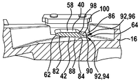
도 9에는, 본 발명의 제 1 실시형태에 따르는 측정 채널 커버(16)의 평면도가 도시되어 있다. 센서 캐리어(40)는 연장 방향(76)을 따라서 측정 채널(28) 내로 연장된다. 연장 방향(76)은 측정 채널(28) 내에서 유체 매체의 주 유동 방향(60)에 대해 실질적으로 수직이다.9 is a plan view of the
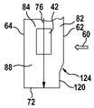
도 10에는, 제 1 실시형태에 따르는 측정 채널 커버(16)의 횡단면도가 도시되어 있다. 센서 캐리어(40)는 코드(78)를 포함한다. 코드(78)는 4.5㎜ 내지 6.5㎜, 예컨대 5.5㎜의 길이를 갖는다. 따라서, 센서 캐리어(40)는 측정 채널(28) 내에서 유체 매체의 주 유동 방향(60)으로 볼 때 종래의 센서 캐리어보다 훨씬 더 짧게 형성되며, 센서 캐리어의 코드는 적어도 7.0㎜의 길이를 갖는다. 센서 캐리어(40)의 횡단면의 두께(80)는 0.5㎜ 내지 3.0㎜, 예컨대 1.0㎜일 수 있다. 종래의 실시형태와 달리, 도 10에 도시된 실시형태는 라운딩된 후방 에지부(64)를 포함한다. 그에 따라, 센서 캐리어(40)는 제 1 실시형태의 경우 라운딩된 전방 에지부 또는 유입 에지부(62) 및 라운딩된 후방 에지부(64)를 포함한다. 그 결과, 센서 캐리어(40)는 이중 타원형의 형태로 형성된다.10 is a cross-sectional view of the
도 11에는, 제 2 실시형태에 따르는 측정 채널 커버(16)의 횡단면도가 도시되어 있다. 하기에서는, 선행 실시형태와의 차이점만이 설명되고 동일한 부품들에는 동일한 도면부호가 부여된다. 센서 캐리어(40)는 측정 채널(28) 내에서 유체 매체의 주 유동 방향(60)과 관련하여 센서 칩(42) 상류의 유입 섹션(82)과 센서 칩(42) 하류의 유출 섹션(84)을 포함한다. 유출 섹션(84)은 적어도 부분적으로 라운딩되거나, 또는 적어도 부분적으로 쐐기형으로 형성된다. 도시된 실시예의 경우, 유출 섹션(84)은 스프링보드(86)의 형태로 형성된다. 그에 상응하게, 센서 캐리어(40)는 센서 칩(42)의 면 상에, 다시 말해 상면(88) 상에, 센서 칩(42)의 영역에서 평면 표면이 계속될 때, 협폭 횡단면(90)을 포함하며, 이 횡단면의 에지부들(92)은 이 실시예에서 상이한 크기의 반경들(94, 96)을 가질 수 있다. 이와 반대로, 센서 칩(42)으로부터 떨어져 있는 하면(58) 상에서는 윤곽이 2개의 반경(98, 100)을 경유하여 상면(88)의 방향으로 복귀하며, 후방 에지부(64) 상에서 마찬가지로 반경을 갖는다. 마이크로 사출 성형 방법에서, 실제로 최소 0.1㎜까지의 반경들이 실현된다. 후방 에지부(64)의 영역에서 최대 2㎜의 값을 갖는 상대적으로 더 큰 반경뿐만 아니라, 하면(58)의 복귀하는 윤곽의 영역에서 0.1㎜ 내지 10㎜의 값을 갖는 반경들도 가능하다.Fig. 11 shows a cross-sectional view of the
도 12에는, 제 2 실시형태에 따르는 센서 캐리어(40)의 사시도가 도시되어 있다. 여기에는, 특히 유출 섹션(84)의 스프링보드 유형의 형성이 나타난다. 또한, 횡단면 윤곽의 다양한 반경들(94, 96, 98, 100)도 나타난다.Fig. 12 shows a perspective view of the
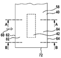
도 13에는, 제 3 실시형태에 따르는 센서 캐리어(40)의 저면도가 도시되어 있다. 하기에는, 선행 실시형태들과의 차이점만이 설명되고 동일한 부품들에는 동일한 도면부호가 부여된다. 여기에는 센서 캐리어(40)의 상면(88) 상에 센서 칩(42)의 위치가 예시되어 있다.13 is a bottom view of the
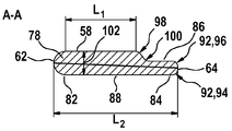
도 14에는, 도 13의 절단선 A-A를 따르는 센서 캐리어(40)의 횡단면도가 도시되어 있다. 제 3 실시형태의 센서 캐리어(40)의 경우 유출 섹션(84)은 코드(78)와 관련하여 대칭으로 형성된다.Fig. 14 shows a cross-sectional view of the
도 15에는, 도 13의 절단선 B-B를 따르는 센서 캐리어(40)의 횡단면도가 도시되어 있다. 제 3 실시형태의 센서 캐리어(40)의 경우, 유출 섹션(84)은 코드(78)와 관련하여 대칭으로 형성된다. 그러나 센서 캐리어(40)는 센서 칩(42)의 영역에서 나머지 영역들에서보다 더 두꺼운 두께를 갖는다. 도 13의 절단선 A-A 및 B-B를 따르는 횡단면들에서 이 특별한 형성이 분명하게 확인된다. 이렇게, 센서 캐리어(40)는, 도 13의 절단선 A-A를 따라서, 도 13의 절단선 B-B를 따르는 두께(104)에 비해 더 두꺼운 두께(102)를 갖는다.Fig. 15 shows a cross-sectional view of the
도 16에는, 제 4 실시형태에 따르는 센서 캐리어(40)의 횡단면도가 도시되어 있다. 하기에는, 선행 실시형태들과의 차이점만이 설명되고 동일한 부품들에는 동일한 도면부호가 부여된다. 이 경우, 단면은 도 13의 절단선 A-A를 따라서 연장된다. 여기서는 센서 캐리어(40)의 상면(88) 상에 센서 칩(42)의 위치가 예시되어 있다. 제 4 실시형태는 제 2 실시형태를 기반으로 하고 제 3 실시형태의 상세내용들을 조합한 것이다. 여기서는 유출 섹션(84) 상에 스프링보드(86)를 갖는 센서 캐리어(40)와 횡단면 윤곽의 해당 위치에 형성된 반경들(92,94, 98, 100)이 나타난다.Fig. 16 shows a cross-sectional view of the
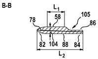
도 17에는, 도 13의 절단선 B-B를 따르는 센서 캐리어(40)의 횡단면도가 도시되어 있다. 센서 캐리어(40)는, 센서 칩(42)의 영역에서, 나머지 영역들에서보다 더 두꺼운 두께를 갖는다. 제 4 실시형태에 대한 도 13의 절단선 A-A 및 B-B를 따르는 횡단면들에서 이 특별한 형성이 분명하게 확인된다. 이렇게, 센서 캐리어(40)는, 제 4 실시형태에 대한 도 13의 절단선 A-A를 따라서, 제 4 실시형태에 대한 도 13의 절단선 B-B를 따르는 두께(104)에 비해 더 두꺼운 두께(102)를 갖는다. 또한, 하면(58)으로부터 스프링보드(86)로 향하는 전이부는 스플라인(105)(spline)의 형태로 형성될 수 있다.Figure 17 shows a cross-sectional view of
도 18에는 제 5 실시형태에 따르는 센서 캐리어(40)의 횡단면도가 도시되어 있다. 센서 캐리어(40)의 상면 상에는 돌출부(106)가 배치된다. 도 18에는 제 4 실시형태에 따르는 센서 캐리어(40)의 횡단면도가 도시되어 있다. 하기에는, 선행 실시형태들과의 차이점만이 설명되고 동일한 부품들에는 동일한 도면부호가 부여된다. 제 3 실시형태의 센서 캐리어(40)의 경우, 유출 섹션(84)은 코드(78)와 관련하여 대칭으로 형성된다. 유출 섹션(84) 상에서 센서 캐리어(40)는 돌출부(106)를 포함한다. 돌출부(106)는 후방 에지부(64) 상에 위치되고 이 후방 에지부로부터 상면(88)의 방향으로 돌출된다.18 is a cross-sectional view of the
도 19에는 제 5 실시형태의 센서 캐리어(40)의 확대 횡단면도가 도시되어 있다. 여기서는 돌출부(106)가 나타난다. 돌출부(106)는 단차형으로 형성되며, 그럼으로써 돌출부(106)는 직사각형 횡단면을 갖는다. 돌출부(106)는 측정 채널(28) 내 주 유동 방향(60)에서 센서 칩(42)과의 0.5㎜ 내지 2.0㎜, 예컨대 1.0㎜의 간격(108)을 갖는다. 돌출부(106)는 0.1㎜ 내지 0.4㎜, 예컨대 0.2㎜의 폭(110)을 갖는다. 돌출부(106)는 상면(88) 또는 센서 칩(42)의 레벨과 -0.2㎜ 내지 0.4㎜, 예컨대 0.1㎜의 간격(112)으로 이격되어 배치된다. 돌출부(106)는 반드시 직사각형 횡단면을 가질 필요는 없다. 예컨대 삼각형, 다각형 또는 라운딩된 형태와 같은 또 다른 횡단면 형태들도 가능하다.19 is an enlarged cross-sectional view of the
도 20에는 제 6 실시형태에 따르는 센서 캐리어(40)의 평면도가 도시되어 있다. 하기에는, 선행 실시형태들과의 차이점만이 설명되고 동일한 부품들에는 동일한 도면부호가 부여된다. 제 6 실시형태의 경우, 돌출부(106)는 구획부(114)로서 형성된다. 달리 말하면, 돌출부(106)는 복수의 불연속부를 포함하며, 그럼으로써 돌출부(106)는 일렬로 배치되는 복수의 세그먼트로 구성되며, 이 복수의 세그먼트는 센서 칩(42)의 측정 채널(28) 내 주 유동 방향(60)과 관련하여 하류에 배치되고 연장 방향(76)에 대해 평행하게 배치된다.20 is a plan view of the
도 21에는, 제 7 실시형태에 따르는 센서 캐리어(40)의 측면도가 도시되어 있다. 하기에는, 선행 실시형태들과의 차이점만이 설명되고 동일한 부품들에는 동일한 도면부호가 부여된다. 제 7 실시형태의 경우, 센서 캐리어(40)는 후방 에지부(64) 상에 돌출부(106) 대신 노치부 또는 공동부(116)를 포함한다. 공동부(116)는 0.1㎜ 내지 0.25㎜, 예컨대 0.15㎜의 높이(118)를 갖는다. 공동부(116)는 후방 에지부(64)의 전체 길이에 걸쳐서 연장 방향(76)으로 연장된다. 그 대안으로, 공동부(116)는 후방 에지부(64)의 일부분에 걸쳐서만 연장된다.Fig. 21 shows a side view of the
도 22에는, 제 8 실시형태에 따르는 센서 캐리어(40)의 평면도가 도시되어 있다. 하기에는, 선행 실시형태들과의 차이점만이 설명되고 동일한 부품들에는 동일한 도면부호가 부여된다. 제 8 실시형태의 경우, 유입 에지부(62)는 노치부 또는 공동부(120)를 포함한다. 공동부(120)는 유입 에지부(62)의 전체 길이에 걸쳐서 연장 방향(76)으로 연장되는 것이 아니라, 연장 방향(76)에서 간격(122) 내에 배치된다. 공동부(120)는, 센서 캐리어(40)가 선단면(72)의 방향으로 갈수록 가늘어지는 방식으로 형성된다. 이 경우, 센서 캐리어(40)는, 결과적으로 다시 유입 에지부(62)에 대해 평행한 섹션(126)으로 전이되는 섹션(124)에 걸쳐 선형으로 가늘어질 수 있다. 테이퍼 섹션(124)은 연장 방향(76)으로 0.5㎜ 내지 5.0㎜, 예컨대 2.0㎜의 치수(128)를 가질 수 있다. 공동부(120)는 0.5㎜ 내지 3.5㎜, 예컨대 1.0㎜의 깊이(130)를 가질 수 있다.Fig. 22 shows a plan view of the
도 23에는 제 9 실시형태에 따르는 센서 캐리어(40)의 평면도가 도시되어 있다. 하기에는 선행 실시형태들과의 차이점만이 설명되고 동일한 부품들에는 동일한 도면부호가 부여된다. 제 9 실시형태의 경우, 유입 에지부(62)는 마찬가지로 노치부 또는 공동부(120)를 포함한다. 그러나 섹션(124)은 선형으로 가늘어지는 것이 아니라, 연속적인 곡률을 갖는다.Fig. 23 shows a plan view of the
도 24에는 제 10 실시형태에 따르는 센서 캐리어(40)의 평면도가 도시되어 있다. 하기에는 선행 실시형태들과의 차이점만이 설명되고 동일한 부품들에는 동일한 도면부호가 부여된다. 제 10 실시형태의 경우, 센서 캐리어(40)는 유입 에지부(62) 상에 제 1 공동부(132) 및 제 2 공동부(134)를 포함한다. 그 밖에도, 센서 캐리어는 후방 에지부(64) 상에 제 3 공동부(136)를 포함한다. 제 1 공동부(132)는 선단면(72)에 대향하여 위치하는 센서 캐리어(40)의 단부(138)로부터 연장 방향(76)으로 지점(140)까지 연장되며, 이 지점은 선단면(72)으로 향해 있는 센서 칩(42)의 단부(142)로부터 연장 방향으로 -2.0㎜ 내지 2.0㎜, 예컨대 -1.0㎜의 간격(144)만큼 이격되어 있다. 제 1 공동부(132)는 0.2㎜ 내지 1.0㎜, 예컨대 0.5㎜의 깊이(146)를 갖는다. 이에 인접하여, 측정 채널 내 주 유동 방향(60)과 반대 방향으로 향해 있는 돌출부(150)까지 선형으로 연장되는 전이 섹션(148)이 형성된다. 전이 섹션(148)은 연장 방향(76)으로 0.1㎜ 내지 2.0㎜, 예컨대 0.5㎜의 치수(152)를 갖는다. 선단면(72)으로 향하는 연장 방향(76)에서, 제 2 공동부(134)는 돌출부(150)에 인접하면서 선단면(72)의 방향으로 갈수록 센서 캐리어(40)를 선형으로 가늘어지게 형성한다. 제 2 공동부(134)는 연장 방향(76)으로 0.1㎜ 내지 2.0㎜, 예컨대 0.5㎜의 치수(154)를 갖는다. 제 2 공동부(134)는 자신의 가장 깊은 위치에서 0.2㎜ 내지 1.0㎜, 예컨대 0.5㎜의 깊이(156)를 갖는다. 제 3 공동부(136)는, 연장 방향(76)과 반대 방향으로, 선단면(72)으로 향해 있는 센서 칩(42)의 단부(142)로부터 -1.0㎜ 내지 2.0㎜, 예컨대 1.0㎜의 간격(160)만큼 오프셋 되어 있는 위치(158)로부터 연장된다. 제 3 공동부(136)는 선형으로 가늘어지는 전이 섹션(162)과 후방 에지부(64)에 대해 평행하게 연장되는 섹션(164)을 포함한다. 선형으로 가늘어지는 섹션(162)은 연장 방향(76)으로 0.5㎜ 내지 3.0㎜, 예컨대 1.5㎜의 치수(166)를 갖는다. 후방 에지부(64)에 대해 평행하게 연장되는 섹션(164)은 0.2㎜ 내지 1.5㎜, 예컨대 0.75㎜의 깊이(168)를 갖는다.24 is a plan view of the
도 25에는, 제 11 실시형태에 따르는 센서 캐리어(40)의 저면도가 도시되어 있다. 하기에는 선행 실시형태들과의 차이점만이 설명되고 동일한 부품들에는 동일한 도면부호가 부여된다. 제 11 실시형태의 경우, 센서 캐리어(40)는 연장 방향(76)에서 선단면(72) 쪽으로 갈수록 가늘어진다. 예컨대 후방 에지부(64)는 0° 내지 20°, 예컨대 10°의 제 1 각도(α)로 선형으로 가늘어지며, 유입 에지부(62)는 0° 내지 30°, 예컨대 10°의 제 2 각도(β)로 선형으로 가늘어진다. 제 1 각도(α) 및 제 2 각도(β)는 그 크기와 관련하여 서로 상이하거나 동일할 수 있다.Fig. 25 shows a bottom view of the
도 26에는, 제 12 실시형태에 따르는 센서 캐리어(40)의 저면도가 도시되어 있다. 하기에는 선행 실시형태들과의 차이점만이 설명되고 동일한 부품들에는 동일한 도면부호가 부여된다. 제 12 실시형태의 경우, 후방 에지부(64)는 0.1㎜ 내지 2.0㎜, 예컨대 1.0㎜의 제 1 반경(170)에서 선단면(72)으로 이어진다. 유입 에지부(62)는 0.1㎜ 내지 2.0㎜, 예컨대 1.0㎜의 제 2 반경(172)에서 선단면(72)으로 이어진다. 그 밖에도, 선단면(72)은 사인파형 공동부들(174)을 포함한다. 사인파형 공동부들(174)은, 그 형태가 0.4㎜ 내지 5.0㎜, 예컨대 1.0㎜의 파장(176)을 갖도록 형성된다.Fig. 26 shows a bottom view of the
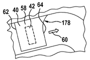
도 27에는, 제 13 실시형태에 따르는 센서 캐리어(40)의 저면도가 도시되어 있다. 하기에는 선행 실시형태들과의 차이점만이 설명되고 동일한 부품들에는 동일한 도면부호가 부여된다. 제 13 실시형태의 경우, 후방 에지부(64)는 0.1㎜ 내지 10.0㎜, 예컨대 5.0㎜의 반경(178)에서 측정 채널(28)의 인접하는 채널 벽부로 이어진다. 측정 채널(28)의 인접하는 채널 벽부로 비접선형 이어짐도 가능하다.Fig. 27 shows a bottom view of the
10: 센서 장치
12: 센서 하우징
14: 하우징 몸체
16: 측정 채널 커버
18: 전자 유닛 챔버
20: 전자 유닛 챔버 커버
22: 채널 구조
24: 주 채널
26: 하면
28: 바이패스 또는 측정 채널
30: 선단면
32: 바이패스 또는 측정 채널 유출구
34: 유입 개구부
36: 주 유동 방향
38: 전자 모듈
40: 센서 캐리어
42: 센서 칩
44: 센서 멤브레인
46: 바닥판
48: 인쇄회로기판
50: 제어 및 평가 회로
52: 전기 결선
54: 원심력 편향부
56: 측정 채널 램프
58: 배면 또는 하면
60: 주 유동 방향
62: 전방 에지부 또는 유입 에지부
64: 후방 에지부
66: 벽 섹션
68: 벽 섹션
70: 간극
71: 간극
72: 선단면
73: 후류 영역
74: 분리 및 재순환 영역
76: 연장 방향
78: 코드
80: 두께
82: 유입 섹션
84: 유출 섹션
86: 스프링보드
88: 상면
90: 협폭 횡단면
92: 에지부
94: 반경
96: 반경
98: 반경
100: 반경
102: 두께
104: 두께
105: 스플라인
106: 돌출부
108: 간격
110: 폭
112: 간격
114: 구획부
116: 공동부
118: 높이
120: 공동부
122: 간격
124: (테이퍼) 섹션
126: 섹션
128: 치수
130: 깊이
132: 제 1 공동부
134: 제 2 공동부
136: 제 3 공동부
138: 단부
140: 지점
142: 단부
144: 간격
146: 깊이
148: 전이 섹션
150: 돌출부
152: 치수
154: 치수
156: 깊이
158: 위치
160: 간격
162: 전이 섹션
164: 섹션
166: 치수
168: 깊이
170: 제 1 반경
172: 제 2 반경
174: 공동부
176: 파장
178: 반경10: Sensor device
12: Sensor housing
14: housing body
16: Measurement channel cover
18: Electronic unit chamber
20: Electronic unit chamber cover
22: Channel structure
24: main channel
26: When
28: Bypass or measurement channel
30: cross section
32: Bypass or measurement channel outlet
34: inlet opening
36: Main flow direction
38: Electronic module
40: sensor carrier
42: Sensor chip
44: Sensor membrane
46:
48: printed circuit board
50: control and evaluation circuit
52: Electrical connection
54: centrifugal force deflection part
56: Measurement channel lamp
58: back or bottom
60: main flow direction
62: front edge portion or inflow edge portion
64: rear edge portion
66: wall section
68: Wall section
70: Clearance
71: clearance
72: cross section
73: wake area
74: separation and recirculation zone
76: Extension direction
78: Code
80: Thickness
82: Inflow section
84: spill section
86: Springboard
88: upper surface
90: Narrow cross section
92: edge portion
94: Radius
96: Radius
98: Radius
100: Radius
102: Thickness
104: Thickness
105: spline
106: protrusion
108:
110: Width
112:
114:
116: Cavity
118: Height
120: Cavity
122:
124: (taper) section
126: Sections
128: Dimensions
130: Depth
132: first cavity
134: second cavity
136: Third Cavity
138: end
140: branch office
142: end
144:
146: Depth
148: Transition section
150: protrusion
152: Dimensions
154: Dimensions
156: Depth
158: Location
160:
162: transition section
164: Sections
166: Dimensions
168: Depth
170: 1st radius
172: 2nd radius
174: Cavity
176: Wavelength
178: Radius
Claims (12)
상기 코드(78)는 4.5㎜ 내지 6.5㎜의 길이를 갖는 것을 특징으로 하는 센서 장치(10).A sensor device (10) for measuring at least one parameter of a fluid medium, in particular an internal combustion engine, flowing through a measurement channel (28), the sensor device (10) comprising a sensor housing (12) A plug-in sensor in which the measurement channel 28 can be formed and inserted or inserted into the flow tube and at least one sensor chip 42 disposed in the measurement channel 28 for measuring the parameters of the fluid medium Wherein the sensor chip is mounted on a sensor carrier protruding into the measurement channel and the sensor carrier is configured to include a cord, In the device 10,
Characterized in that the cord (78) has a length of 4.5 mm to 6.5 mm.
Applications Claiming Priority (3)
| Application Number | Priority Date | Filing Date | Title |
|---|---|---|---|
| DE102014217870.3 | 2014-09-08 | ||
| DE102014217870.3A DE102014217870A1 (en) | 2014-09-08 | 2014-09-08 | Sensor arrangement for determining at least one parameter of a fluid flowing through a measuring channel |
| PCT/EP2015/066733 WO2016037750A1 (en) | 2014-09-08 | 2015-07-22 | Sensor arrangement for determining at least one parameter of a fluid medium flowing through a measurement channel |
Publications (2)
| Publication Number | Publication Date |
|---|---|
| KR20170047263A true KR20170047263A (en) | 2017-05-04 |
| KR102497876B1 KR102497876B1 (en) | 2023-02-10 |
Family
ID=53673107
Family Applications (1)
| Application Number | Title | Priority Date | Filing Date |
|---|---|---|---|
| KR1020177006333A KR102497876B1 (en) | 2014-09-08 | 2015-07-22 | Sensor arrangement for determining at least one parameter of a fluid medium flowing through a measurement channel |
Country Status (7)
| Country | Link |
|---|---|
| US (1) | US10444047B2 (en) |
| EP (1) | EP3191804B1 (en) |
| JP (1) | JP6334818B2 (en) |
| KR (1) | KR102497876B1 (en) |
| CN (1) | CN106716078B (en) |
| DE (1) | DE102014217870A1 (en) |
| WO (1) | WO2016037750A1 (en) |
Cited By (1)
| Publication number | Priority date | Publication date | Assignee | Title |
|---|---|---|---|---|
| KR20230123283A (en) | 2022-02-16 | 2023-08-23 | 김영자 | Smart door lock device linked to a blockchain-based contact app |
Families Citing this family (6)
| Publication number | Priority date | Publication date | Assignee | Title |
|---|---|---|---|---|
| DE102014218591A1 (en) * | 2014-09-16 | 2016-03-17 | Robert Bosch Gmbh | Sensor arrangement for determining at least one parameter of a flowing through a channel structure fluid medium |
| JP6568593B2 (en) * | 2015-09-30 | 2019-08-28 | 日立オートモティブシステムズ株式会社 | Physical quantity detection device |
| JP6654239B2 (en) * | 2016-06-07 | 2020-02-26 | 日立オートモティブシステムズ株式会社 | Thermal flow meter |
| WO2018120733A1 (en) * | 2016-12-30 | 2018-07-05 | 北京金风科创风电设备有限公司 | Electrical connector, fluid state test device, and fluid heat exchange system |
| CN108267261B (en) * | 2016-12-30 | 2019-12-13 | 北京金风科创风电设备有限公司 | Electric connector, fluid state testing device and fluid heat exchange system |
| JP6905962B2 (en) * | 2018-07-12 | 2021-07-21 | 日立Astemo株式会社 | Flow sensor |
Citations (2)
| Publication number | Priority date | Publication date | Assignee | Title |
|---|---|---|---|---|
| US4829814A (en) * | 1987-06-09 | 1989-05-16 | Hitachi, Ltd. | Hot film type air flow meter |
| JP2000241222A (en) * | 1998-12-21 | 2000-09-08 | Mitsubishi Electric Corp | Flow rate measuring apparatus |
Family Cites Families (34)
| Publication number | Priority date | Publication date | Assignee | Title |
|---|---|---|---|---|
| US4478076A (en) * | 1982-09-30 | 1984-10-23 | Honeywell Inc. | Flow sensor |
| DE3606849A1 (en) * | 1986-03-03 | 1987-09-10 | Vdo Schindling | ARRANGEMENT FOR MEASURING THE FLOW RATE |
| US4808009A (en) * | 1986-06-05 | 1989-02-28 | Rosemount, Inc. | Integrated semiconductor resistance temperature sensor and resistive heater |
| US4914947A (en) | 1988-09-30 | 1990-04-10 | Honeywell Inc. | Sampling probe flow sensor |
| US4885938A (en) * | 1988-12-16 | 1989-12-12 | Honeywell Inc. | Flowmeter fluid composition correction |
| DE4009833C2 (en) * | 1989-03-31 | 1996-09-26 | Aisan Ind | Air volume measuring device for intake air |
| JP3133608B2 (en) * | 1994-02-28 | 2001-02-13 | 株式会社ユニシアジェックス | Thermal air flow detector |
| DE4426102C2 (en) | 1994-07-22 | 1997-07-10 | Bosch Gmbh Robert | Sensor carrier for a device for measuring the mass of a flowing medium and method for producing a sensor carrier |
| WO1997022856A1 (en) * | 1995-12-15 | 1997-06-26 | Siemens Aktiengesellschaft | Air mass meter |
| DE19643996A1 (en) * | 1996-10-31 | 1998-05-07 | Bosch Gmbh Robert | Appliance for measuring mass of flowing medium for measuring air intake of IC engines |
| JP3404251B2 (en) * | 1997-04-17 | 2003-05-06 | 三菱電機株式会社 | Flow detector |
| DE19815654A1 (en) | 1998-04-08 | 1999-10-14 | Bosch Gmbh Robert | Measuring device for measuring the mass of a medium flowing in a line |
| JP3385307B2 (en) * | 1998-05-11 | 2003-03-10 | 三菱電機株式会社 | Flow sensor |
| DE19927818C2 (en) * | 1999-06-18 | 2003-10-23 | Bosch Gmbh Robert | Device for measuring the mass of a flowing medium |
| DE19939824A1 (en) * | 1999-08-21 | 2001-02-22 | Bosch Gmbh Robert | Device for measuring flowing medium has sensor bearer, base bearer and measurement element in flowing medium; sensor bearer has plastic element largely covering plate element |
| JP3555017B2 (en) * | 1999-09-22 | 2004-08-18 | 三菱電機株式会社 | Thermal flow sensor |
| US6382024B1 (en) | 2000-06-28 | 2002-05-07 | The United States Of America As Represented By The Administrator Of The National Aeronautics And Space Administration | Thermocouple boundary layer rake |
| DE10036290A1 (en) * | 2000-07-26 | 2002-02-07 | Bosch Gmbh Robert | Device for determining at least one parameter of a flowing medium |
| JP3817497B2 (en) * | 2002-06-10 | 2006-09-06 | 株式会社日立製作所 | Thermal flow meter |
| WO2005008189A1 (en) * | 2003-07-14 | 2005-01-27 | Robert Bosch Gmbh | Device for determining at least one parameter of a medium flowing in a line |
| JP4020208B2 (en) * | 2004-11-30 | 2007-12-12 | 三菱電機株式会社 | Flow measuring device |
| US7194920B2 (en) * | 2005-03-15 | 2007-03-27 | Welker Engineering Company | Sensor probe and pipeline construction and method |
| DE102006045656A1 (en) * | 2006-09-27 | 2008-04-03 | Robert Bosch Gmbh | Flow dynamics improved plug-in sensor |
| DE102006045657A1 (en) * | 2006-09-27 | 2008-04-03 | Robert Bosch Gmbh | Plug-in sensor with optimized flow outlet |
| DE102007024865A1 (en) * | 2007-05-29 | 2008-12-04 | Robert Bosch Gmbh | Device for determining at least one parameter of a fluid medium |
| DE102008042155A1 (en) * | 2008-09-17 | 2010-03-18 | Robert Bosch Gmbh | Sensor arrangement for determining a parameter of a fluid medium |
| DE102008042166A1 (en) * | 2008-09-17 | 2010-03-18 | Robert Bosch Gmbh | Sensor arrangement for determining a parameter of a fluid medium |
| JP5170209B2 (en) * | 2010-10-28 | 2013-03-27 | 株式会社デンソー | Flow measuring device |
| DE102011076170A1 (en) * | 2011-05-20 | 2012-11-22 | Robert Bosch Gmbh | Device for detecting at least one property of a flowing fluid medium |
| JP5755185B2 (en) * | 2012-06-15 | 2015-07-29 | 日立オートモティブシステムズ株式会社 | Thermal flow meter |
| KR20140003020A (en) * | 2012-06-28 | 2014-01-09 | 삼성전기주식회사 | Light emitting diode driving apparatus |
| DE102012224049A1 (en) * | 2012-12-20 | 2014-06-26 | Robert Bosch Gmbh | Sensor device for detecting at least one flow characteristic of a fluid medium |
| JP6118150B2 (en) * | 2013-03-21 | 2017-04-19 | 日立オートモティブシステムズ株式会社 | Thermal flow meter |
| DE102014202853A1 (en) * | 2014-02-17 | 2015-08-20 | Robert Bosch Gmbh | Sensor arrangement for determining at least one parameter of a fluid flowing through a channel |
-
2014
- 2014-09-08 DE DE102014217870.3A patent/DE102014217870A1/en active Pending
-
2015
- 2015-07-22 JP JP2017513135A patent/JP6334818B2/en active Active
- 2015-07-22 EP EP15738709.3A patent/EP3191804B1/en active Active
- 2015-07-22 US US15/509,116 patent/US10444047B2/en active Active
- 2015-07-22 WO PCT/EP2015/066733 patent/WO2016037750A1/en active Application Filing
- 2015-07-22 KR KR1020177006333A patent/KR102497876B1/en active IP Right Grant
- 2015-07-22 CN CN201580048186.0A patent/CN106716078B/en active Active
Patent Citations (2)
| Publication number | Priority date | Publication date | Assignee | Title |
|---|---|---|---|---|
| US4829814A (en) * | 1987-06-09 | 1989-05-16 | Hitachi, Ltd. | Hot film type air flow meter |
| JP2000241222A (en) * | 1998-12-21 | 2000-09-08 | Mitsubishi Electric Corp | Flow rate measuring apparatus |
Cited By (1)
| Publication number | Priority date | Publication date | Assignee | Title |
|---|---|---|---|---|
| KR20230123283A (en) | 2022-02-16 | 2023-08-23 | 김영자 | Smart door lock device linked to a blockchain-based contact app |
Also Published As
| Publication number | Publication date |
|---|---|
| DE102014217870A1 (en) | 2016-03-10 |
| EP3191804A1 (en) | 2017-07-19 |
| CN106716078B (en) | 2019-10-25 |
| US20170261359A1 (en) | 2017-09-14 |
| JP2017526929A (en) | 2017-09-14 |
| KR102497876B1 (en) | 2023-02-10 |
| CN106716078A (en) | 2017-05-24 |
| JP6334818B2 (en) | 2018-05-30 |
| US10444047B2 (en) | 2019-10-15 |
| WO2016037750A1 (en) | 2016-03-17 |
| EP3191804B1 (en) | 2022-01-12 |
Similar Documents
| Publication | Publication Date | Title |
|---|---|---|
| KR20170047263A (en) | Sensor arrangement for determining at least one parameter of a fluid medium flowing through a measurement channel | |
| US9217655B2 (en) | Sensor system for determining at least one flow property of a fluid medium flowing in a main flow direction | |
| JP4904024B2 (en) | Apparatus for measuring at least one parameter of a medium flowing in a conduit | |
| US8607624B2 (en) | Sensor system for determining a parameter of a fluid medium | |
| KR101398827B1 (en) | Plug-in sensor with improved flow dynamics | |
| US8978455B2 (en) | Sensor device for detecting at least one flow property of a fluid medium | |
| JP6194852B2 (en) | Air flow measurement device with humidity detection function | |
| KR102267810B1 (en) | Sensor arrangement for determining at least one parameter of a fluid medium flowing through a channel structure | |
| KR102447065B1 (en) | Sensor arrangement for determining at least one parameter of a fluid medium flowing through a channel structure | |
| RU2678213C2 (en) | Measuring device for determining at least one parameter of fluid medium flowing through channel | |
| KR20140010082A (en) | Apparatus for recording at least one property of a fluid medium | |
| KR101009271B1 (en) | Device for determining at least one parameter of a medium flowing in a line | |
| KR102301752B1 (en) | Sensor arrangement for determining at least one parameter of a fluid medium flowing through a channel | |
| JP3848934B2 (en) | Air flow measurement device | |
| JP7122462B2 (en) | physical quantity detector | |
| JP6674917B2 (en) | Thermal flow meter | |
| US11067420B2 (en) | Sensor for determining at least one parameter of a fluid medium streaming through a measuring channel | |
| KR102466025B1 (en) | Sensor for determining at least one parameter of a fluid medium flowing through a measuring channel | |
| DE102011089483A1 (en) | Sensor assembly for determining parameter or flow characteristic of fluid medium, particularly intake air mass of internal combustion engine, has channel formed in a sensor plug, and sensor chip for determining parameter of fluid medium |
Legal Events
| Date | Code | Title | Description |
|---|---|---|---|
| A201 | Request for examination | ||
| E902 | Notification of reason for refusal | ||
| E902 | Notification of reason for refusal | ||
| E701 | Decision to grant or registration of patent right | ||
| GRNT | Written decision to grant |