KR20170047191A - Tape applicator Assembly and tape assembly - Google Patents
Tape applicator Assembly and tape assembly Download PDFInfo
- Publication number
- KR20170047191A KR20170047191A KR1020167023803A KR20167023803A KR20170047191A KR 20170047191 A KR20170047191 A KR 20170047191A KR 1020167023803 A KR1020167023803 A KR 1020167023803A KR 20167023803 A KR20167023803 A KR 20167023803A KR 20170047191 A KR20170047191 A KR 20170047191A
- Authority
- KR
- South Korea
- Prior art keywords
- tape
- assembly
- cable
- hub
- funnel
- Prior art date
Links
Images


Classifications
-
- B—PERFORMING OPERATIONS; TRANSPORTING
- B65—CONVEYING; PACKING; STORING; HANDLING THIN OR FILAMENTARY MATERIAL
- B65H—HANDLING THIN OR FILAMENTARY MATERIAL, e.g. SHEETS, WEBS, CABLES
- B65H37/00—Article or web delivery apparatus incorporating devices for performing specified auxiliary operations
- B65H37/04—Article or web delivery apparatus incorporating devices for performing specified auxiliary operations for securing together articles or webs, e.g. by adhesive, stitching or stapling
-
- B—PERFORMING OPERATIONS; TRANSPORTING
- B65—CONVEYING; PACKING; STORING; HANDLING THIN OR FILAMENTARY MATERIAL
- B65H—HANDLING THIN OR FILAMENTARY MATERIAL, e.g. SHEETS, WEBS, CABLES
- B65H35/00—Delivering articles from cutting or line-perforating machines; Article or web delivery apparatus incorporating cutting or line-perforating devices, e.g. adhesive tape dispensers
- B65H35/0006—Article or web delivery apparatus incorporating cutting or line-perforating devices
- B65H35/002—Hand-held or table apparatus
- B65H35/0026—Hand-held or table apparatus for delivering pressure-sensitive adhesive tape
- B65H35/0033—Hand-held or table apparatus for delivering pressure-sensitive adhesive tape and affixing it to a surface
-
- H—ELECTRICITY
- H02—GENERATION; CONVERSION OR DISTRIBUTION OF ELECTRIC POWER
- H02G—INSTALLATION OF ELECTRIC CABLES OR LINES, OR OF COMBINED OPTICAL AND ELECTRIC CABLES OR LINES
- H02G1/00—Methods or apparatus specially adapted for installing, maintaining, repairing or dismantling electric cables or lines
- H02G1/06—Methods or apparatus specially adapted for installing, maintaining, repairing or dismantling electric cables or lines for laying cables, e.g. laying apparatus on vehicle
-
- H—ELECTRICITY
- H02—GENERATION; CONVERSION OR DISTRIBUTION OF ELECTRIC POWER
- H02G—INSTALLATION OF ELECTRIC CABLES OR LINES, OR OF COMBINED OPTICAL AND ELECTRIC CABLES OR LINES
- H02G3/00—Installations of electric cables or lines or protective tubing therefor in or on buildings, equivalent structures or vehicles
- H02G3/30—Installations of cables or lines on walls, floors or ceilings
- H02G3/305—Mounting by adhesive material
-
- B—PERFORMING OPERATIONS; TRANSPORTING
- B65—CONVEYING; PACKING; STORING; HANDLING THIN OR FILAMENTARY MATERIAL
- B65H—HANDLING THIN OR FILAMENTARY MATERIAL, e.g. SHEETS, WEBS, CABLES
- B65H2301/00—Handling processes for sheets or webs
- B65H2301/50—Auxiliary process performed during handling process
- B65H2301/51—Modifying a characteristic of handled material
- B65H2301/516—Securing handled material to another material
-
- B—PERFORMING OPERATIONS; TRANSPORTING
- B65—CONVEYING; PACKING; STORING; HANDLING THIN OR FILAMENTARY MATERIAL
- B65H—HANDLING THIN OR FILAMENTARY MATERIAL, e.g. SHEETS, WEBS, CABLES
- B65H2701/00—Handled material; Storage means
- B65H2701/10—Handled articles or webs
- B65H2701/11—Dimensional aspect of article or web
- B65H2701/113—Size
- B65H2701/1133—Size of webs
- B65H2701/11332—Size of webs strip, tape, narrow web
-
- B—PERFORMING OPERATIONS; TRANSPORTING
- B65—CONVEYING; PACKING; STORING; HANDLING THIN OR FILAMENTARY MATERIAL
- B65H—HANDLING THIN OR FILAMENTARY MATERIAL, e.g. SHEETS, WEBS, CABLES
- B65H2701/00—Handled material; Storage means
- B65H2701/30—Handled filamentary material
- B65H2701/37—Tapes
- B65H2701/377—Adhesive tape
Abstract
테이프를 표면에 부착하는 테이프 적용기 어셈블리는 몸체를 포함하고, 디스펜싱(dispensing)하는 동안에 자동적으로 몸체 내에서 테이프 어셈블리 중심을 잡고 잠그는 센터링(centering) 및 잠금(locking) 어셈블리를 포함할 수 있다. 테이프 적용기 어셈블리는 적어도 하나의 케이블과 표면을 고정할 수 있고, 몸체는 테이프 중심 길이방향 축을 가지는 테이프를 구비한 테이프 어셈블리를 수용하게 정의된 테이프 수용 중공을 포함할 수 있다. 테이프 적용 어셈블리는, 적어도 하나의 케이블과 표면에 테이프를 부착하도록, 몸체 내부에 정의될 수 있다. 케이블 정렬 어셈블리는, 표면에 위치된 적어도 하나의 케이블을 수용하고 실질적으로 적어도 하나의 케이블을 테이프 중심 길이방향 축으로 정렬하도록, 몸체 내부에 정의될 수 있다.The tape applicator assembly that attaches the tape to a surface may include a body and may include a centering and locking assembly that locks and locks the tape assembly center within the body automatically during dispensing. The tape applicator assembly may include at least one cable and a surface, and the body may include a tape receiving cavity defined to receive a tape assembly having a tape having a longitudinal center axis of the tape. The tape application assembly may be defined within the body to attach the tape to at least one cable and surface. The cable alignment assembly may be defined within the body to receive at least one cable positioned on the surface and to substantially align at least one cable with the tape center longitudinal axis.
Description
테이프 적용기 어셈블리에 관한 것이다.Tape applicator assembly.
개퍼 테이프(Gaffer tape)는 압력에 민감한 접착 테이프의 특화된 한 타입으로, 안전상 또는 방청객이나 카메라로부터 케이블들을 보이지 않게 하기 위하여 무대 바닥 또는 다른 표면에 케이블을 고정하는 목적으로 엔터테인먼트 산업에서 종종 사용된다. 또한, 호텔 및 컨퍼런스 센터에서 단상 및 무대에 선들을 유지하기 위하여 음향 영상 부서에 의해 널리 이용된다. Gaffer tape is a specialized type of pressure sensitive adhesive tape that is often used in the entertainment industry for the purpose of securing cables to the stage floor or other surface for safety or to hide cables from the audience or camera. It is also widely used by audio-visual departments to maintain single-phase and stage lines at hotels and conference centers.
"담당자" 또는 다른 기술자는 종종 둘 또는 이상의 위치 사이에 하나 이상의 케이블을 이어주고(이하에서는 종종 "케이블 이음"이라고 칭함), 케이블을 바닥에 테이프로 고정한다. 예를 들면, 전기 콘센트와 오디오 장비 사이에 바닥, 벽 또는 다른 표면에 테이프 접착된 상태로 케이블 이음이 연장된다. 케이블 이음이 테이핑 되기 이전에나 케이블 이음이 다른 표면에 테이프 접착된 이후에, 케이블 이음이 무리 지어지고, 펴지고, 당겨지는 것이 종종 요구된다. 테이프 접착될 케이블 이음을 정렬하고 무리 짓는 것은 테이프 라인을 직선화하고, 사용되는 테이프의 스트립을 최소화하고, 걸어 넘어뜨리는 어떠한 위험을 줄이고, 케이블 이음을 미적으로 더 좋게 만든다. "Person in charge" or other descriptor often links one or more cables between two or more locations (hereinafter often referred to as "cable splicing ") and tape the cable to the floor. For example, the cable connection extends between the electrical outlet and the audio equipment with the tape adhered to the floor, wall, or other surface. It is often required that the cable joint be clumped, stretched, and pulled before the cable joint is taped or after the cable joint is tape bonded to the other surface. Aligning and jamming the cable joints to be tape bonded will straighten the tape lines, minimize the strips used, reduce any risk of hanging, and make the cable connections aesthetically better.
이러한 방식으로 케이블 이음을 정렬하고 무리 짓는 것은 노동집약적이고 불완전한 과정임을 알 수 있다. 담당자는 한 손으로 케이블 이음을 무리 짓고 정렬하고 당기면서 다른 손으로 케이블 이음을 표면에 테이핑 하여야 한다. 그러므로, 정렬되고 무리 지어지고 위치된 케이블을 표면에 고정하는 개선된 장치 및 방법이 요구된다.It can be seen that aligning and bundling cable joints in this way is labor intensive and incomplete. The person in charge should tie the cable joints with one hand while taping the cable joints with the other hand while aligning and pulling. Therefore, there is a need for an improved apparatus and method for securing aligned, crowded and positioned cables to a surface.
상술한 바와 같이, 개퍼 테이프는 표면에 케이블 이음을 테이프 접착시키는데 이용되는 압력에 민감한 접착 테이프의 특화된 종류이다. 테이프가 소정의 힘으로 손으로 제거될 때까지는 압력에 민감한 접착물질은 케이블 이음을 표면에 고정하도록 충분히 강하다. (덕 테이프와 같이 조잡한 테이프와 달리) 개퍼 테이프는 케이블로부터 깨끗하게 제거됨이 요구됨에도 불구하고, 테이프는 케이블들의 주변을 감싸고 케이블 사이에서 접힐 수 있어서, 제거 과정 동안에 테이프가 그 자체에 접착된다. 더불어, 케이블들이 테이프로 표면에 접착(gaffed)될 때, 접착 잔존물이 케이블에 쌓여지고 케이블에서 테이프를 제거하는 것이 더욱 어렵게 된다. 그러므로, 케이블을 개핑(gaffing)하는데 사용이 적합한 개선된 테이프 어셈블리가 요구된다.As noted above, gap tape is a specialized type of pressure sensitive adhesive tape used to tape bond cable joints to the surface. The pressure sensitive adhesive material is strong enough to secure the cable joint to the surface until the tape is manually removed with a predetermined force. The tape can wrap around the cables and be folded between the cables, so that the tape adheres to itself during the removal process (unlike rough tapes like duct tape), although the gap tape is required to be cleanly removed from the cable. In addition, when the cables are gaffed to the surface with tape, the adhesive residues accumulate on the cable and it becomes more difficult to remove the tape from the cable. Therefore, there is a need for an improved tape assembly that is suitable for use in gaffing cables.
테이프를 표면에 부착하는 테이프 적용기 어셈블리는 몸체를 포함하고, 디스펜싱(dispensing)하는 동안에 자동적으로 몸체 내에서 테이프 어셈블리 중심을 잡고 잠그는 센터링(centering) 및 잠금(locking) 어셈블리를 포함할 수 있다. 테이프 적용기 어셈블리는 적어도 하나의 케이블과 표면을 고정할 수 있고, 몸체는 테이프 중심 길이방향 축을 가지는 테이프를 구비한 테이프 어셈블리를 수용하게 정의된 테이프 수용 중공을 포함할 수 있다. 테이프 적용 어셈블리는, 적어도 하나의 케이블과 표면에 테이프를 부착하도록, 몸체 내부에 정의될 수 있다. 케이블 정렬 어셈블리는, 표면에 위치된 적어도 하나의 케이블을 수용하고 실질적으로 적어도 하나의 케이블을 테이프 중심 길이방향 축으로 정렬하도록, 몸체 내부에 정의될 수 있다. 요약은 간략한 형태로 선택 가능한 개념들을 소개하도록 제공되고, 아래의 상세한 설명에서 보다 기술된다. 요약은 청구하는 내용의 주요 특징들을 확인하지 않으며, 청구하는 내용의 범위를 정하는 데에 도움으로 사용되는 것이 의도되지 않는다.The tape applicator assembly that attaches the tape to a surface may include a body and may include a centering and locking assembly that locks and locks the tape assembly center within the body automatically during dispensing. The tape applicator assembly may include at least one cable and a surface, and the body may include a tape receiving cavity defined to receive a tape assembly having a tape having a longitudinal center axis of the tape. The tape application assembly may be defined within the body to attach the tape to at least one cable and surface. The cable alignment assembly may be defined within the body to receive at least one cable positioned on the surface and to substantially align at least one cable with the tape center longitudinal axis. The summary is provided to introduce selectable concepts in a simplified form and is described further in the detailed description below. The summary does not identify key features of the claimed subject matter, nor is it intended to be used as an aid in determining the scope of the claimed subject matter.
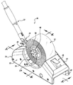
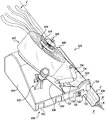
도 1은 테이프 적용기 어셈블리 및 테이프 어셈블리의 사시도이고, 테이프 적용기 어셈블리 및 테이프 어셈블리는 표면으로 케이블 이음을 테이핑하는 사용 시를 나타낸다.
도 2는 실질적으로 2-2선을 가로 질러서 얻어진 도 1의 테이핑된 케이블 이음의 단면도이다.
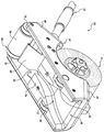
도 3은 도 1의 테이프 적용기 어셈블리 및 테이프 어셈블리의 부분적인 상방의 사시도이다.
도 4는 도 1의 테이프 적용기 어셈블리 및 테이프 어셈블리의 부분적인 하방의 사시도이다.
도 5는 도 3의 테이프 적용기 어셈블리 및 테이프 어셈블리의 부분적인 단면도이고, 테이프 적용기 어셈블리 및 테이프 어셈블리는 케이블을 표면에 테이핑하는 사용상태를 나타낸다.
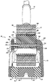
도 6은 실질적으로 6-6선을 가로질러 얻어진, 도 3의 테이프 적용기 어셈블리 및 테이프 어셈블리의 부분적인 단면도이다.
도 7은 도 1의 테이프 어셈블리의 사시도이다.
도 8A는 테이프 적용기 어셈블리의 제1 대안적 실시예의 하방 사시도이고, 테이프 적용기 어셈블리는 케이블을 표면에 테이핑하는 사용 시를 나타낸다.
도 8B는 도 8A의 테이프 적용기 어셈블리의 상방 사시도이고, 테이프 적용기 어셈블리의 부분은 도시를 위하여 제거되어 있다.
도 9는 테이프 적용기 어셈블리의 제2 대안적 실시예의 전방 사시도이고, 테이프 적용기 어셈블리는 케이블을 표면에 테이핑하는 사용 시를 나타낸다.
도 10은 도 9의 테이프 적용기 어셈블리의 후방 사시도이다.
도 11은 도 9의 테이프 적용기 어셈블리의 하방 사시도이다.
도 12는 도 9의 테이프 적용기 어셈블리의 부분에 대하여 부분적 제거된 사시도이다.
도 13은 도 9의 테이프 적용기 어셈블리의 하방 사시도이고, 테이프 적용기 어셈블리는 케이블을 표면에 테이핑하는 것을 나타낸다.
도 14는 테이프 적용기 어셈블리의 제3 대안적 실시예의 하방 사시도이다.
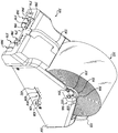
도 15는 테이프 적용기 어셈블리의 제4 대안적 실시예의 전방 사시도이고, 테이프 적용기 어셈블리는 모서리에 케이블을 테이핑하는 사용 시를 나타낸다.
도 16은 도 15의 테이프 적용기 어셈블리의 측면 사시도이다.
도 17은 도15의 테이프 적용기 어셈블리의 하방 사시도이다.
도 18은 도 15의 테이프 적용기 어셈블리 하면도이다.
도 19는 도 1의 테이프 적용기 어셈블리의 센터링 및 잠금 어셈블리의 제1 대안적 실시예의 사시도이다.
도 20은 도 1의 테이프 적용기 어셈블리의 센터링 및 잠금 어셈블리의 제2 대안적 실시예의 사시도이다.1 is a perspective view of a tape applicator assembly and a tape assembly, and a tape applicator assembly and a tape assembly illustrate use when taping a cable joint to a surface.
2 is a cross-sectional view of the taped cable joint of FIG. 1 taken substantially across line 2-2.
Figure 3 is a partially upper perspective view of the tape applicator assembly and tape assembly of Figure 1;
Figure 4 is a partially downward perspective view of the tape applicator assembly and tape assembly of Figure 1;
FIG. 5 is a partial cross-sectional view of the tape applicator assembly and tape assembly of FIG. 3, and the tape applicator assembly and tape assembly illustrate a use condition taping the cable to a surface.
Figure 6 is a partial cross-sectional view of the tape applicator assembly and tape assembly of Figure 3, obtained substantially across 6-6 lines.
Figure 7 is a perspective view of the tape assembly of Figure 1;
8A is a bottom perspective view of a first alternative embodiment of a tape applicator assembly, wherein the tape applicator assembly illustrates the use of taping a cable to a surface.
Figure 8B is an upper perspective view of the tape applicator assembly of Figure 8A, and a portion of the tape applicator assembly is removed for illustration.
Figure 9 is a front perspective view of a second alternative embodiment of a tape applicator assembly, wherein the tape applicator assembly illustrates the use of taping a cable to a surface.
Figure 10 is a rear perspective view of the tape applicator assembly of Figure 9;
Figure 11 is a bottom perspective view of the tape applicator assembly of Figure 9;
Figure 12 is a partially removed perspective view of a portion of the tape applicator assembly of Figure 9;
Figure 13 is a bottom perspective view of the tape applicator assembly of Figure 9, and the tape applicator assembly illustrates taping the cable to the surface.
Figure 14 is a bottom perspective view of a third alternative embodiment of the tape applicator assembly.
Figure 15 is a front perspective view of a fourth alternative embodiment of a tape applicator assembly, wherein the tape applicator assembly illustrates use when taping a cable to an edge.
Figure 16 is a side perspective view of the tape applicator assembly of Figure 15;
Figure 17 is a bottom perspective view of the tape applicator assembly of Figure 15;
Figure 18 is a bottom view of the tape applicator assembly of Figure 15;
Figure 19 is a perspective view of a first alternative embodiment of the centering and locking assembly of the tape applicator assembly of Figure 1;
Figure 20 is a perspective view of a second alternative embodiment of the centering and locking assembly of the tape applicator assembly of Figure 1;
본 발명 개시의 예시적 실시예에 따른 테이프 적용기 어셈블리(10) 및 테이프 어셈블리(12)는 도 1에 참조됨에 의해 가장 잘 나타난다. 도 2를 부가적으로 참조하면, 테이프 적용기 어셈블리(10)는, 하나 이상의 케이블(C)을 무리 짓고, 정렬하고, 팽팽하게 하여 하나의 케이블 이음(R)이 되도록 하고, 케이블 이음(R)을 표면에 테이프 부착시킨다. 테이프 적용기 어셈블리(10)가 케이블 이음(R)을 표면에 테이프 부착시키기 위하여 사용되는 것으로 설명될 것이나, 테이프 적용기 어셈블리(10)가 다른 적당한 목적에 사용될 수 있다. 예를 들면, 테이프 적용기 어셈블리(10)는, 케이블들(C)을 표면에 테이핑 하기에 적당한 개퍼 테이프를 포함하는 테이프 어셈블리(12)와 같이 사용될 수 있다. 대안적으로, 어플리케이터 어셈블리는, 임시적인 장치를 고정하거나 라벨링(labeling)하고, 좌석도, 벽, 보도, 경계 등을 표시하기에 적당한 다른 테이프를 포함하는 테이프 어셈블리(12)와 같이 사용될 수 있다. 따라서, 여기에서 제공된 설명과 도시들은 청구하는 내용의 범위를 제한하는 것을 보아서는 아니 된다.The
테이프 적용기 어셈블리(10)는 몸체(14) 및 이에 고정된 핸들 어셈블리(18)를 포함한다. 핸들 어셈블리(18)는 밀고, 조종하고 표면의 몸체(14)를 다루는 데에 적합하다. 어떠한 적절한 핸들 어셈블리(18)가 사용될 수 있지만, 묘사되는 실시예에서 핸들 어셈블리(18)는 몸체(14)로부터 위로 연장된 대(stem, 22)를 포함하고, 피봇(pivot) 연결(28)이나 다른 적당한 수단들을 통하여 몸체(14)에 피봇이 되게 연결될 수 있다. 대(22)는 길이 조절이 가능하고, 사용자가 사용을 위해 몸체(14)를 잡으려고 할 경우에 제거가 가능할 수 있다. 적절한 핸들은 대(22)의 말단에서 핸들 어셈블리(18)를 잡을 수 있도록 정의된다. 부가적인 잡기 도구, 핸들 등이 밀고, 조종하고 표면의 몸체(14)를 다루는데 적합하도록 대에 고정될 수 있다.The
몸체(14)는 제거 가능하게 테이프 어셈블리(12)의 부분을 수용하고 케이블 이음(R)을 표면에 테이핑 하기에 적합하다. 케이블 이음(R)을 표면에 테이핑 하기 이전에, 미관적으로 좋고 안전한 테이핑 부착된 케이블 이음(R)을 위해 몸체(14)는 하나 이상의 케이블들(C)을 모으고, 정렬하고, 무리 짓고, 팽팽하게 한다.The
도 3-6을 참조하면, 하나 이상의 케이블들을 모으고, 정렬하고, 무리 짓고, 팽팽하게 하고 표면에 테이핑 하는 몸체(14)에 대하여 상세히 설명될 것이다. 특히 도 3을 참조하면, 후방부(40)과 전방부(32) 사이에 정의된 테이프 수용 중공(36)을 가지는 상방부(32)를 포함한다. 표면 상의 원하는 케이블(C)을 따라 몸체(14)를 앞으로 밀기 위하여 핸들 대(22)는 후방부(40)에 피봇이 되게 고정된다.3-6, a
케이블 정렬 어셈블리는, 표면을 따라 몸체(14)를 이동할 때에 표면에 위치된 하나 이상의 케이블을 수용하고 실질적으로 정렬하도록 몸체 내에 정의된다. 케이블 정렬 어셈블리는, 전방부에 고정되거나 다르게 전방부(44) 상에 정의되는 레이저(46)나 다른 빛을 이용한 센터링 방식과 같은 정렬도구를 포함할 수 있다. 사용자가 케이블을 직선으로 테이핑 하게 안내하도록 레이저는 빔을 표면 상에 비출 수 있다.The cable alignment assembly is defined within the body to receive and substantially align one or more cables positioned on the surface as the body moves along the surface along the surface. The cable alignment assembly may include an alignment tool, such as a
케이블 정렬 어셈블리는 전방 케이블 개구(48)를 더 포함할 수 있고, 전방 케이블 개구(48)는 레이저(46) 아래에 몸체(14)의 전방 단부에 정의되고, 테이프 적용기 어셈블리(10)가 표면 상의 케이블들을 따라 이동될 때 표면에 위치된 하나 이상의 케이블을 수용하기 적합하다. 도 4를 참조하면, 전방 케이블 개구(48)는, 바닥, 내부, 몸체(14)의 열린 면을 따라 후방으로 연장되고 후방 케이블 개구(54)에서 끝나는 깔때기(funnel, 52)와 통하게 된다. 깔때기(52)는, 테이핑되기 이전에 케이블을 모으고 무리 짓기 위하여 전방 및 후방 케이블 개구(54) 사이에 폭 방향으로 가늘어 진다.The cable alignment assembly may further include a
깔때기(52)는, 후방 케이블 개구(54)의 크기를 조절하기 위하여, 깔때기(52)의 후단부에 제거가능 및/또는 조정 가능한 후방 깔때기 부품(56)을 포함할 수 있다. 묘사되는 실시예에서, 후방 깔때기 부품(56)은 적당한 스냅-핏(snap-fit) 기술이나 다른 적당한 수단들로 제거 가능하게 몸체(14)의 바닥 내에 고정된다. 후방 깔때기 부품(56)은 제거되고 테이핑을 위하여 더 많거나 적게 케이블(C)을 무리 짓기 위하여 후방 케이블 개구(54)를 더 크거나 작게 정의하는 다른 후방 깔때기 부품(56)으로 대체/교환될 수 있다. 대안적으로, 후방 깔때기 부품(56)은, 어떠한 부분의 제거를 필요로 하지 않고 후방 케이블 개구(54)의 크기를 조절하기 위한 조절 수단들을 포함할 수 있다.The
후방 깔때기(52)의 크기와 형상은, 원하는 방식으로 테이핑 될 수 있게 하나 이상의 케이블들(C)을 배치할 수 있도록 구성될 수 있음이 이해되어야 한다. 예를 들면, 후방 깔때기 부품(56)은, 하나의 케이블(C)이 중심에 오도록 센터링하고 표면에 테이프로 테이핑 하기 위하여, 작은 중심 개구를 포함할 수 있다. 다른 예에 따라, 후방 깔때기 부품(56)은, 수개의 케이블들(C)을 센터링하고 무리 짓기 위하여, 더 깊고 넓은 개구를 포함할 수 있다. 또 다른 예에서, 후방 깔때기 부품(56)은, 테이핑을 위해 수개의 케이블들(C)을 나란히 배치하기 위하여(도 2를 참조), 더 넓고 얕은 개구를 포함할 수 있다. 따라서, 후방 깔때기(52)의 크기, 모양 및 구성은 원하는 형태의 사용을 위하여 설계될 수 있음을 알 수 있다.It should be appreciated that the size and shape of the
케이블 정렬 어셈블리는 적당한 바이어싱(biasing) 또는 장력(tensioning) 부재를 더 포함할 수 있고, 하나 이상의 케이블(C)이 몸체(14)를 통하여 공급될 때 압력 및 장력을 케이블(C)에 적용하기 위하여 깔때기(52)의 후방에 배치된다. 묘사되는 실시예에서, 몸체(14)가 표면 상의 케이블들(C)을 따라 이동할 때에, 장력 부재는 모아진 케이블들(C)을 몸체(14)로부터 멀리, 다시 말해 표면을 향하여, 치우치게 하는 판 스프링(60)을 포함되어 있다. 그 점과 관련하여, 판 스프링(60)은 상단부가 몸체(14)의 내측 부분에 고정되고, 원래의 치우치지 않은 상태에서 하방으로 연장되어 바닥, 내부, 몸체(14)의 열린 면을 지나고 몸체(14)의 후방을 향한다. 케이블(C)이 맞물릴 때에 판 스프링(60)은 위쪽으로 유연하게 치우진 위치로 이동된다. 치우친 위치에서, 판 스프링(60)은 연속적으로 케이블(C)과 맞물리고 케이블(C)이 표면(S)을 향하도록 몰다. 케이블들(C)에 연속적으로 장력을 가함으로써, 케이블들(C)은 당겨지고 펴지며 테이프가 부착될 때에 중심에서 유지되고 무리 지어진다.The cable alignment assembly may further include suitable biasing or tensioning members and may apply pressure and tension to the cable C when one or more cables C are supplied through the
테이프 적용 어셈블리는 몸체(14) 내에 정의되고, 표면 상에 정렬되고 무리 지어지고 펴진 케이블들(C)에 테이프를 적용하도록 케이블 정렬 어셈블리와 소통된다. 테이프 적용 어셈블리는, 케이블(C)과 표면에 같이 테이프를 부착하기 위하여 판 스프링(60)의 뒤에 위치된 후방 휠(rear wheel) 어셈블리(66)를 포함한다.The tape application assembly is defined within the
도 4 및 5를 참조하면, 후방 휠 어셈블리(66)는 측면 후방 롤링 휠(lateral rear rolling wheel) 74와 78 사이에 놓인 중간 테이프 적용 부분(70)을 포함한다. 측면 후방 롤링 휠 74와 78은 몸체(14) 내부 면의 각 측면에 배치되고, 후방 휠 어셈블리(66)를 통과하여 연장되는 핀 또는 막대(분류된 것은 아님)에 의하는 것과 같이 어떠한 적당한 방식으로 몸체(14) 내에서 회전을 위해 축받이 되고(journaled), 몸체(14)의 각 측면 내부 면에 회전 가능하게 수용된다. 몸체(14)가 원하는 표면에 대하여 굴러가게 하기 위하여, 측면 후방 롤링 휠 74와 78이 바닥, 후방, 몸체(14)의 열린 면으로부터 돌출되게, 후방 휠 어셈블리(66)는 몸체(14) 내에 배치된다.Referring to Figures 4 and 5, the
그러한 점에 관하여, 몸체(14)가 원하는 표면에 대하여 쉽게 굴러가게 하도록, 측면 전방 롤링 휠(lateral front rolling wheel) 82 및 86은 바닥, 몸체(14)의 각 내부 측면 상의 몸체(14)의 전방 표면으로부터 돌출된다. 측면 전방 롤링 휠 82 및 86은 깔때기(52)의 각 측면 상에 배치될 수 있고, 각각 전방 롤링 휠 82 및 86을 통과하여 회전 가능하게 연장되는 핀 또는 막대와 같은 적당한 방식으로 몸체(14) 내부에서 회전이 축받이 될 수 있고, 각각의 몸체(14)의 내부 측면 내에서 회전 가능하게 배치될 수 있다. 몸체(14)의 내부의 배치되는 후방 및 전방 측면 롤링 휠 74, 78, 82 및 86을 구비하여, 몸체(14)가 표면을 따라 이동될 때에, 몸체(14)는 측벽 또는 다른 물체에 대하여 쉽게 배치될 수 있다.In that regard, lateral
측면 후방 롤링 휠 74와 78사이에 배치된 중간 테이프 적용 부분(70)은, 표면에 케이블들(C)을 고정시키기 위하여, 무리 지어진 케이블들(C)과 표면을 테이프 부착하고 가압하게 구성된다. 그 점에 관하여, 중간 테이프 적용 부분(70)은 케이블들(C)과 표면을 따라 굴러갈 때에 압력을 가할 수 있도록 충분히 유연하다. 보다 구체적으로, 케이블들(C)을 가압하기 위하여, 중간 테이프 적용 부분(70)은 중간 부분에서 반지름 방향으로 변형, 압축 등이 된다. 케이블들(C)의 양 측면의 표면을 가압하고 표면의 형상에 맞추기 위하여, 중간 테이프 적용 부분(70)은 측면 부분에서 반지름 방향으로 변형, 압축 등이 된다. 케이블들(C)과 어떤 평평하지 않는 표면에도 연속적이고 균일하게 압력을 가할 필요에 따라 중간 및 측면 부분들은 변형될 수 있다. 그 점에 관하여, 중간 테이프 적용 부분(70) 및 케이블(C)/표면 사이에 배치된 테이프를 구비하여, 중간 테이프 적용 부분(70)이 케이블(C)을 따라 굴려질 때에, 테이프는 케이블들(C) 및 표면에 부착된다.The intermediate
중간 테이프 적용 부분(70)의 압축을 맞추기 위하여, 측면 후방 롤링 휠 74와 78은 중간 테이프 적용 부분(70)보다 충분히 작은 지름을 가진다. 이러한 방식으로, 케이블들(C)/표면을 가압하기 위하여 중간 테이프 적용 부분(70)이 압축될 때에, 몸체(14)가 표면을 따라 구를 수 있도록 측면 후방 롤링 휠 74와 78은 표면과 맞물린다. 그러나, 중간 테이프 적용 부분(70)만을 통하여 몸체(14)가 표면을 굴러갈 경우에, 측면 후방 롤링 휠 74와 78는 대신 제거되는 것도 생각될 수 있다.To match the compression of the intermediate
중간 테이프 적용 부분(70)은 케이블들(C)과 표면에 압력을 충분히 가하는 어떠한 적당한 재질로 만들어질 수 있다. 예를 들면, 중간 테이프 적용 부분(70)은 폼(foam), 고무 또는 다른 적당한 재질로 만들어 질 수 있다. 표면과 맞물리는 홈의 양측 상의 케이블들(C)과 측면 부분들을 수용하기 위하여, 중간 테이프 적용 부분(70)은 대신에 중심 방사상의 홈(center radial groove)을 가지는 실질적으로 단단한 것이 될 수 있음이 생각될 수 있다. 측면 부분이 표면 상에서 압력이 유지될 때, 케이블(C)에 압력을 가하기 위하여 홈은 충분히 깊을 수 있다. 따라서, 무리 지어진 케이블들(C)과 표면에 압력을 동시에 가하는 어떠한 적절한 구성도 사용될 수 있음이 생각될 수 있다.The intermediate
상술한 바와 같이, 중간 테이프 적용 부분(70)이 동시에 케이블들(C)과 표면에 테이프를 부착하도록, 중간 테이프 적용 부분(70)과 케이블(C)/표면 사이에 테이프가 공급된다. 테이프는 테이프 어플케이터 어셈블리(tape applicator assembly) 내에 고정된 테이프 어셈블리(12)로부터 내놓아 진다.The tape is fed between the intermediate
도 5-7을 참조하여, 테이프 적용기 어셈블리(10) 내에서 테이프 어셈블리(12)를 고정하는 테이프 어셈블리(12)의 부분 및 구조는 자세하게 기술된다. 테이프 어셈블리(12)는 코어(core) 주변에 감기거나 코어(94) 상에 주변을 둘러싸는 형태로 배치되는 테이프 롤(roll)을 포함한다. 코어(94)는 실질적으로 실린더 형상이고 테이프 롤(90)의 폭에 맞추도록 코어(94) 축의 길이를 정의한다. 코어(94)는 다양한 사이즈의 테이프 롤(90)들, 2인치, 3인치 등등에 맞추도록 어떠한 적당한 코어(94) 축 길이일 수 있다. 코어(94)는 또한 코어(94) 축 길이를 따라 연장되는 내부 실린더 개구를 정의한다. 중공의 실린더 형상의 개구는, 허브(98)를 수용하게 크기 지워지고 구성된 내부 코어(94) 지름을 가진다. 허브(98)는, 테이프 적용기 내에 테이프 어셈블리(12)를 고정하도록, 몸체(14)의 테이프 수용 중공(36) 내에 제거가 가능하게 고정된다.5-7, the portion and structure of the
코어(94)와 같이 허브(98)는 원통형상이고 웹 어셈블리에 의해 정의된다. 웹 어셈블리(116)는 외부 원통형 몸체 부분(120)과 내부 원통형 몸체 부분(122) 사이에 연장되고, 내부 원통형 몸체 부분(122)을 통하여 축방향으로 연장되는 중심 축 관통홀을(118) 구비한다. 웹 어셈블리는 허브(98)의 비용과 무게를 감소시킴이 이해될 수 있다. 그러나, 허브(98)는 외부 및 내부 원통형 몸체 부분(120, 122) 사이에 연장되는 속이 찬 몸체로 대신 정의될 수 있다.Like the core 94, the
허브(98)는 코어(94)의 내부 지름과 실질적으로 같은 외부 지름을 나타낸다. 이러한 방식으로, 코어(94)는 테이프 적용기 어셈블리(10) 내에서 사용할 수 있는 허브(98) 상에 제거 가능하나 안정적으로 배치된다. 98은, 코어(94) 내에서 제거 가능하게 수용되게 크기 지워진 허브 축 길이를 규정한다. 허브(98)는 다양한 크기의 코어(94)를 수용하기 위하여 어떠한 적절한 축 길이를 가질 수 있으며, 동시에 몸체(14)의 테이프 수용 중공(36) 내에서 수용되게 크기 지워지고 구성될 수 있다.The
코어 센터링 및 잠금 어셈블리(100)는 코어(94)와 허브(98) 상의 코어(94)를 잠그고 센터링하는 허브(98) 사이에 정의된다. 어떠한 적절한 센터링 및 잠금 어셈블리가 사용될 수 있으나, 묘사된 실시예에서 코어 센터링 및 잠금 어셈블리(100)는 돌기 또는 너브(nub, 102)와 같은 제1 잠금 구성을 포함할 수 있다. 제1 잠금 구성은 고리형상의 홈(106)(an annular groove)과 같은 제2 잠금 구성 내에서 수용될 수 있게 허브(98)의 외부면 상에 정의되고, 제2 잠금 구성은 허브(98) 상의 코어(94)를 고정하도록 코어(94)의 내부면 상에 정의된다. 너브(102)는 대신 허브(98) 상에 정의되고, 고리형상의 홈(106)이 코어(94) 상에 정의되는 것은 이해될 수 있다.The core centering and locking
너브(102) 및 고리형상의 홈(106)은 허브(98) 및 코어(94) 상에 각각 위치되어서, 너브(102)가 고리형상의 홈(106) 내에 수용될 때에 허브(98) 상에 코어(94)가 자동적으로 축의 방향으로 중심이 맞추어 진다. 다시 말해, 너브(102)는 대체로 허브(98) 상에서 축방향으로 중심 맞추어 지고, 고리형상 홈은 대체로 코어(94) 상에 축방향으로 중심 맞추어 진다. 이러한 방식으로, 너브(102)가 고리형상 홈(106) 내에 수용될 때에 코어(94)는 허브(98) 상에 자동적으로 축방향으로 중심 맞추어 진다. 코어(94) 상에 홈이 축방향으로 중심 맞추어 지면, 축방향 길이에 무관하게(예를 들어, 축방향 길이가 1인치, 2인치, 3인치 등등) 코어(94)는 자동적으로 허브(98) 상에 중심 맞추어질 수 있음이 이해될 수 있다.The
테이프 어셈블리(12)는 허브 잠금 어셈블리(110)를 통하여 허브(98) 상에 추가로 고정된다. 허브 잠금 어셈블리(110)는 몸체(14) 내에 고정되고 테이프 수용 중공(36) 안으로 연장된 샤프트(130)에 의해 정의된다. 샤프트(130)는, 앵커 돌출부 내에 고정되고 몸체(14)의 한쪽 면으로부터 상방으로 연장되는 제1 단부에 정의된 앵커를 포함한다. 샤프트(130)는 테이프 수용 중공(36) 안으로 실질적으로 가로질러 앵커 돌출부(138)로 연장되어서, 샤프트(130)는 실질적으로 몸체(14)의 바닥면과 평행하다.The
이러한 방식으로 테이프 수용 중공(36) 안으로 샤프트(130)가 연장되면, 테이프 적용기 어셈블리(10) 내에 원하는 테이프 롤(90)을 고정하기 위하여 허브(98)는 제거 가능하고 회전 가능하게 샤프트(130) 상에 고정될 수 있다. 중심 관통홀을 통하여 샤프트(130)를 지나게 함으로써, 허브(98)는 제거 가능하고 회전 가능하게 샤프트(130) 상에 고정될 수 있다. 샤프트(130) 상에 수용될 때, 허브(98)는 테이프 분배를 위한 샤프트(130)의 중심 길이방향 축에 대하여 회전이 가능하다.When the
허브(98)의 회전을 수용하기 위하여, 베어링 서브 어셈블리(114)는 샤프트(130)와 허브(98) 사이에 정의된다. 어떠한 적절한 베어링 서브 어셈블리(114)도 사용될 수 있지만, 베어링 서브 어셈블리(114)는, 샤프트(130)와 허브(98)의 내부 원통형 몸체 부분(122) 사이에서 샤프트(130)의 양단부에 배치된 제1 및 제2 플랜지형 부싱(flanged bushing, 144, 148)을 포함한다. 그러한 것과 관련하여, 샤프트(130)의 외부면과 내부 원통형 몸체 부분(122)의 내부면 사이에, 제1 및 제2 플랜지형 부싱(144, 148)을 수용하기 위하여 원통형 틈이 정의된다. 제1 및 제2 플랜지형 부싱(144, 148)은 허브(98)의 중심 관통홀(118) 내에서 고정되어, 부싱들 및 허브(98)는 쉬운 조립과 해체를 위한 조립된 유닛이 될 수 있다.In order to accommodate rotation of the
허브 잠금 어셈블리(110)는, 샤프트(130) 상에서 허브(98)를 선택적으로 잠그게 구성된 고정 서브 어셈블리(152)를 더 포함할 수 있다. 고정 서브 어셈블리(152)는, 샤프트(130)의 제2 단부에서(앵커의 반대) 나사산(thread)이 형성된 개구 내에서 나사결합 가능하게 수용되는 볼트와 같은 잠금장치(156)를 포함할 수 있다. 노브(knob, 160)는 잠금장치의 헤드 주변에 잠금장치(156) 상에 일체로 형성되거나 고정되어, 잠금장치의 나사산 형성된 단부는 노브(160)로부터 돌출된다. 잠금장치(156)에 토크를 가하거나 샤프트(130) 내에 잠금장치(156)의 나사산 단부를 고정하기 위하여, 노브(160)는 사용자에 의해 적절하게 파지될 수 있다. 노브(160)를 허브(98)에 대하여 선택적으로 맞물리게 하고 조여지게 하기 위하여, 와셔(164)는 노브(160)와 허브(98) 사이에 배치될 수 있다. 허브(98)에 대해 노브(160)를 조임으로써, 샤프트(130) 상에서 허브(98)가 회전하는 용이성이 조정된다.The
도 7을 참조하여, 테이프 롤(90)을 가지는 테이프 어셈블리(12)의 예시적인 실시예가 보다 자세하게 기술된다. 테이프 롤(90)은 코어(94) 주변에 감겨진 테이프의 연장된 부분(164)에 의해 정의된다. 테이프(164)는 외부면(168)과 반대의 내부면(172)을 포함한다. 압력에 민감한 접착제(176)는, 롤 상에 있을 때 내부면(172) 상에 배치되고 외부면(168)에 제거 가능하게 고정된다.Referring to Fig. 7, an exemplary embodiment of a
압력 민감한 접착제(176)는, 테이프의 내부면(172) 상에서 테이프의 중심 길이방향 축을 따라 연장되는 중간 접착제 부분(180)을 포함한다. 중간 접착제 부분(180)은, 바닥이나 벽 같은 원하는 표면에 제거 가능하게 부착될 수 있도록 충분히 끈적거리는 제1 및 제2 측면 접착 부분(184, 188) 상에 배치된다. The pressure
중간 접착제 부분(180)은 표면(S)에 테이핑 되는 무리 지어진 케이블(C)에 제거 가능하게 부착된다. 그러한 것과 관련하여, 중간 접착제 부분(180)은, 테이프 어플리케이터 어셈블리를 지나 정렬되고 무리 지어진 케이블들(C)을 커버하고 맞물리도록 충분히 넓게 된다. 중간 접착제 부분(180)의 폭은, 다른 크기의 케이블(C) 무리들을 수용하도록 다양한 테이프 롤(90)들에 따라 변할 수 있다.The intermediate
또한 중간 접착제 부분(180)은, 무리 지어진 케이블들(C)을 해제 가능하게 맞물리도록 제1 및 제2 측면 접착제 부분(184, 188)보다 덜 끈적하다. 중간 접착제 부분(180)은, 중간 접착제 부분(180) 전체에 덮는 덜 끈적한 접착제에 의하여 정의될 수 있다. 대안적으로, 중간 접착제 부분(180)은, 길이 방향 또는 횡 방향 줄무늬나 점 등과 같이 전체적으로 덜 끈적한 영역을 만드는 접착제 코팅 패턴에 의해 정의될 수 있다. 따라서, 덜 끈적한 중간 접착제 영역은 어떠한 적절한 방식으로도 정의될 수 있음이 생각될 수 있다.The intermediate
상술한 바와 같이, 일반적인 개퍼 테이프는 테이프의 내부면 전체를 커버하는 압력 민감한 접착제를 포함하고, 소정의 힘에 의해서 수작업으로 제거될 때까지 표면에 케이블 이음을 충분히 강하게 고정된다. 걸음 등으로 인하여 쉽게 제거되지 않으면서 원하는 표면에 안정적으로 부착되도록 접착제는 충분히 강할 필요가 있다. 그러나, 이러한 강한 접착제는 테이프가 케이블을 감싸게 하거나 사이에 접히게 하는 것을 초래하여, 제거 과정에서 테이프가 자체에 붙는 것을 초래한다. 더불어, 케이블이 종종 "개프될(gaffed)" 때, 접착제 잔유물이 케이블 상에 쌓이고 케이블로부터 테이프의 제거를 어렵게 한다.As noted above, a conventional gap tape includes a pressure sensitive adhesive covering the entire inner surface of the tape, and is secured sufficiently firmly to the surface until it is manually removed by a predetermined force. The adhesive needs to be strong enough to stably adhere to the desired surface without being easily removed due to stepping and the like. However, these strong adhesives result in the tape wrapping or intertwining the cable, resulting in the tape sticking to itself during the removal process. In addition, when the cable is often "gaffed ", adhesive residue builds up on the cable and makes it difficult to remove the tape from the cable.
중간 접착제 부분(180)이 줄어든 끈적임의 경로를 정의하면, 테이프(164)가 표면으로부터 위로 당겨질 때에 테이프(164)는 케이블들(C)로부터 쉽게 제거될 수 있다. 중간 접착제 부분(180)은 적어도 어느 정도는 끈적인다면(예를 들면, 반 건조 경로), 케이블(C)이 표면에 테이핑 될 때에 테이프(164)는 케이블들(C)에 부착될 수 있고 케이블(C)의 정렬과 일직선을 유지하는 것을 도울 수 있다. 예를 들어, 중간 접착제 부분(180)은 제1 및 제2 측면 접착제 부분들의 끈적임에 약 10-30%일 수 있다. 그러나, 중간 접착제 부분(180)은 대신 접착제를 가지지 않을 수 있거나(예를 들어, 건조된 경로), 원하면 30% 끈적임보다 클 수도 있음은 생각될 수 있다. 다시 말해, 케이블들(C)에 해제가 가능한 맞물림을 하는 덜 끈적이는 중간 접착제부분을 정의하기 위하여, 중간 접착제 부분(180)은 제1 및 제2 측면 접착제 부분(184, 188)의 끈적임의0-99%일 수 있다.The
테이프 롤(90) 대신에 테이프 스트립, 판상 또는 테이프 적용기 어셈블리(10) 이외의 사용을 위하여 다른 형태일 수 있다. 더불어, 테이프 적용기 어셈블리(10)가 감소된 끈적임의 중간 접착제 부분(180)을 구비한 테이프 어셈블리(12)와 같이 보여지고 기술되었지만, 테이프 적용기 어셈블리(10)는 대신에 어떠한 적절한 테이프와 같이 이용될 수 있다. 예를 들어, 테이프 적용기 어셈블리(10)가 바닥에 케이블(C)을 테이핑 하기 보다는 바닥 상의 경계 선을 표시하기 위해 사용된다면, 내부 면에 상에 어떠한 적절한 압력 민감한 접착제를 구비한 테이프가 사용될 수 있다. 따라서, 여기서 제공된 설명과 도시들은 청구하는 내용의 범위를 제약하는 것으로 보아서는 아니 된다.May be of other shapes for use other than tape strip, plate or
도 5를 참조하면, 케이블들(C)을 표면에 테이핑 하기 위한 테이프 적용기 어셈블리(10)의 작동이 제공된다. 테이프 적용기 어셈블리(10)를 사용하기 이전에, 테이프의 적당한 폭(다시 말해, 축의 길이)은 의도한 사용에 위해 결정된다. 예를 들면, 2-3 케이블들(C)이 표면에 테이핑 된다면, 예를 들어 2-3인치 폭이고 충분히 넓고 끈적한 중간 접착제 영역을 가지는 테이프 롤(90)이 사용될 수 있다. 대안적으로, 테이프 적용기 어셈블리(10)가 단순히 표면 상에 경계선을 표시하는데 사용된다면, 예시적으로 단지 1인치 폭이고 중간 접착제 부분(180)을 가지지 않는 테이프 롤(90)이 대신 사용될 수 있다. 따라서, 원하는 사용에 따라, 선호하는 테이프 롤(90)이 테이프 적용기 어셈블리(10)의 내에 설치되거나, 테이프 적용기 어셈블리(10) 내에 이미 설치된 테이프 롤(90)과 바꾸어질 수 있다.5, there is provided an operation of a
코어 센터링 및 잠금 어셈블리(100)를 가지고 허브(98) 상에 코어(94)를 중심 맞추고 잠금으로써 테이프 롤(90)은 테이프 적용기 어셈블리(10) 내에 설치된다. 보다 구체적으로, 너브(102)가 고리형상의 홈(106) 내에 수용될 때까지 코어(94)는 허브(98) 상에서 미끄러진다. 너브(102)는 고리형상의 홈(106) 내에 수용될 때에 허브(98) 상에 코어(94)가 적당하게 위치된 것을 나타내기 위하여 스냅-핏(snap-fit) 촉각 느낌이 사용자에게 느껴질 수 있음이 생각될 수 있다. 적절한 조립을 돕기 위하여, 표지, 설명 등이 몸체(14), 코어(94) 및/또는 허브(98)의 외부 상에 제공될 수 있다.The
허브(98) 상에 조립된 코어(94)를 구비하여, 허브 잠금 어셈블리(110)를 통하여 허브(98)는 몸체(14) 내에 고정될 수 있다. 보다 구체적으로, 샤프트(130)를 허브(98)의 중심 관통홀(118)을 통하여 지나게 함으로써 허브(98)는 샤프트(130) 상에 고정된다. 그러면 테이프 적용기 어셈블리(10) 내에서 테이프 롤(90)의 회전을 위한 샤프트(130) 상에 허브(98)를 고정하기 위하여, 잠금장치(156)는 샤프트(130) 내에 고정된다. 와셔(164)에 대한 노브(160)의 긴장을 증가시키거나 감소시키기 위하여, 잠금장치(156)는 조여지거나 풀어질 수 있다. 노브(160)로부터 긴장이 증가되면, 테이프 롤(90)은 덜 쉽고 덜 빠르게 풀려진다. 따라서, 노브(160)의 긴장은 원함에 따라 조정됨이 생각될 수 있다.The
코어(94)가 테이프 적용기 어셈블리(10) 내에 고정되면, 테이프(164)를 디스펜싱(dispensing)하는 위치시키도록 테이프 롤(90)은 부분적으로 풀릴 수 있다. 대안적으로, 허브(98) 상에 코어(94)를 고정하기 전에 테이프 롤(90)은 부분적으로 풀릴 수 있다. 테이프(164)는 테이프 롤(90)에서 몸체(14)의 바닥, 내부, 열린 면으로부터 하방으로 후방 휠 어셈블리(66)를 지나서 당겨진다. 테이프의 단부는, 케이블 이음(R)의 제1 단부를 정의하게 표면(S) 및/또는 케이블들(C)에 고정될 수 있다. Once the
테이프 텐셔너(tensioner, 194)는, 테이프가 테이프 롤(90)에서 제공될(dispensed) 때에 테이프(164)에서 장력을 유지시키기 위하여 테이프 롤(90)과 후방 휠 어셈블리(66) 사이에 몸체(14)의 안쪽 내에 배치될 수 있다. 테이프 텐셔너(194)는 몸체(14)의 내부 면 안에서 회전을 위하여 축지지 되는 적절한 롤러 또는 다른 기구일 수 있다. 테이프에서 효율적으로 장력을 유지하기 위하여, 테이프 텐셔너(194)는 테이프 롤(90)과 후방 휠 어셈블리(66) 사이에 정의된 접선으로부터 하방으로 위치된다. 이러한 방식으로, 테이프가 제공될 때 실질적으로 일정한 장력을 유지하기 위하여, 테이프 텐셔너(194)는 테이프에 하방으로 힘을 가한다. 테이프에 장력이 있으면, 후방 휠 어셈블리(66)는 표면/케이블들에 대한 더 나은 테이프 정렬을 유지하고 주름, 틈 등을 줄인다.A
테이프가 후방 휠 어셈블리(66) 위로 지날 때 케이블들(C)과 표면(S)에 압력을 가하기 위하여, 중간 테이프 적용 부분(70)은 부분적으로 압축한다. 보다 상세하게, 깔때기(52)를 통하여 지난 후에 케이블들(C)이 중심으로 정렬되면 (그리고 판 스프링(60)에 의하여 유지되면), 표면에 대한 케이블(C)의 높이 및 형상을 수용하기 위하여 중간 테이프 적용 부분(70)의 중심부는 압축한다. 더불어, 테이프 아래의 케이블들(C)을 밀봉하기 위하여, 케이블들(C)의 양쪽 측면에서 표면(S)에 압력을 중간 테이프 적용 부분(70)의 측면 모서리들이 압축한다.The intermediate
상술한 내용으로부터, 테이프 적용기 어셈블리(10)와 테이프 어셈블리(12)는, 테이프가 되돌릴 수 없게 부착되거나 케이블에 잔류물이 남지 않고도, 정렬되고 무리 지어지고 위치된 케이블들을 표면에 고정하는 장점을 제공할 수 있음이 생각될 수 있다.It will be appreciated from the foregoing that the
도 8A 및 8B를 참조하면, 테이프 적용기 어셈블리(210)의 제1 대안적인 실시예가 그려진다. 테이프 적용기 어셈블리(210)는, 여기에 지시되는 차이점들을 제외하고 실질적으로 상술된 테이프 적용기(10)와 동일하다.Referring to Figures 8A and 8B, a first alternative embodiment of the
그 점과 관련하여, 테이프 적용기 어셈블리(210)는, 몸체(214)의 전방으로부터 바닥을 따라 연장되는 깔때기(252)를 구비하는 케이블 정렬 어셈블리를 포함한다. 깔때기(252)는, 몸체(214)가 표면을 따라 이동할 때 몸체(214)의 전방에서 하나 이상의 케이블들을 수용할 수 있게 하는 전방 케이블 개구(248) 및 후방 케이블 개구(254)를 정의한다. 도 8A 및 8B에 나타난 바와 같이, 후방 케이블 개구(254)는 하나 이상의 케이블들(C)을 하나의 케이블 이음(R)으로 무리 지어지고 정렬시키고 케이블 이음(R)을 표면에 테이핑 한다. 더불어, 후방 케이블 개구(254)는, 다양한 크기의 케이블들과 케이블들의 묶음을 수용하기 위하여, 모듈식의 깔때기/휠 조정 어셈블리(256)를 통하여 크기 및 형상이 조정될 수 있다.In that regard, the
모듈식의 깔때기/휠 조정 어셈블리(256)는, 몸체(214)의 아래쪽 내에서 제거가 가능하게 수용되는 제1 조정 깔때기 부품(257)에 의해 정의될 수 있다. 제1 조정 깔때기 부품(257)은, 깔때기(252)의 후방에 배치되는 후방 깔때기 부분(258) 및 후방 깔때기 부분(258)으로부터 후방으로 연장되는 휠 부분(253)에 의해 부분적으로 정의된다. 소정의 크기의 하나 이상의 케이블들을 표면에 정렬하고 무리 짓고 부착하기 위하여, 후방 깔때기 부분(258)은 실질적으로 크기에서 휠 부분(253)과 대응된다. 묘사되는 실시예에서, 제1 소정의 크기인 케이블(C)을 표면에 정렬하고 부착하기 위하여, 제1 조정 깔때기 부품(257)의 후방 깔때기 부분(258) 및 휠 부분(253)은 대응되는 크기 및 형상을 가진다.The modular funnel /
후방 깔때기 부분(258)은 깔때기(252)의 후방 부분과 케이블(C) 정렬을 위한 후방 케이블 개구(254)를 정의한다. 몸체(214) 내부에 수용될 때, 후방 깔때기 부분(258)은 전방 케이블 개구(248)와 후방 케이블(C) 개수 사이에 그리고 소통되는 길쭉한(elongated) 개구(262)를 정의한다. 길쭉한 개구(262)는 소정의 크기의 하나 이상의 케이블들을 무리 짓고 정렬하기 위한 적절한 단면 형상, 폭 및/또는 깊이이다. 묘사되는 실시예에서, 길쭉한 개구(262)는 제1 소정의 크기의 케이블 정렬을 위하여 적절한 단면 형상, 폭 및/또는 깊이이다. 제2 단면 형상과 더 넓게 및 /또는 더 깊게 길쭉한 개구(262)를 가지는 제2 조정 부품은, 더 큰 케이블 또는 더 큰 케이블 번들을 수용하도록 사용될 수 있다. 반면에, 제3 단면 형상과 더 좁게 및 /또는 더 얇게 길쭉한 개구(262)를 가지는 제3 조정 부품은, 더 작은 케이블 또는 더 작은 케이블 번들을 수용하도록 사용될 수 있다. 길쭉한 개구(262)의 형상 및 크기가 실질적으로 하나 이상의 케이블들의 형상 및 크기에 대응되면, 테이프 적용 어셈블리에 의해 부착되기 이전에 케이블들은 정렬되고 무리 지어진다.The
소정의 크기의 하나 이상의 케이블들을 표면에 테이핑 하기 위하여 휠 부분(253)이 적절한 크기이면, 테이프 적용 어셈블리는 부분적으로 제1 조정 깔때기 부품(257)의 휠 부분(253)에 의해 정의된다. 테이프(268) 및 하나 이상의 케이블들에 압력을 가하기 위하여, 후방 휠 어셈블리(266)와 같이 휠 부분은 몸체(214) 내에서 후방 휠 어셈블리(266)를 회전이 가능하게 고정한다. 그런 점에서 휠 부분(253)은, 후방 깔때기 부분(258)에서 몸체(214)의 후방으로 연장되는 제1 및 제2 휠 어셈블리 암들을 포함한다. 휠 어셈블리 암들(260, 261)은 안에서 후방 휠 어셈블리(266)를 회전이 가능하게 수용한다.The tape application assembly is defined in part by the
후방 휠 어셈블리(266)는 측면 후방 롤링 휠(lateral rear rolling wheel) 274 및 278 사이에 배치된 중간 테이프 적용 부분(270)을 포함한다. 중간 테이프 적용 부분(270)은, 표면 및 하나 이상의 케이블들에 테이프(268)를 고정하기 위하여, 표면 및 하나 이상의 케이블(C)을 가압할 수 있게 충분히 유연하다. 도 8A 및 8B에 나타난 바와 같이, 중간 테이프 적용 부분(270)은, 제1 소정의 크기의 케이블(C) 및 케이블(C)의 양 측면에 표면 부분을 가압할 수 있도록 충분히 넓다. 더불어, 다른 조정 깔때기 부품(257)을 이용함으로써 중간 테이프 적용 부분(270)의 폭은 조정될 수 있다.The
좀 더 상세히, 제1 조정 깔때기 부품(257, 길쭉한 개구(262) 및 제1 소정의 크기와 형상의 중간 테이프 적용 부분(270)을 가짐)은 제거되거나 제2 조정 깔때기 부품(257, 길쭉한 개구(262) 및 제2 소정의 크기의 중간 테이프 적용 부분(270)을 가짐)으로 교체될 수 있다. 이처럼, 조정 깔때기 부품(257)은 제거되거나, 다양한 사이즈의 케이블들 및/또는 번들 또는 케이블들 수용하기 위하여 필요에 따라 교체될 수 있다. 그렇게 함으로써 깔때기(252) 또는 후방 휠 어셈블리(266)의 개별적 조정을 피할 수 있다.More specifically, the first conditioning funnel part 257 (having elongated opening 262 and intermediate
깔때기/휠 조정 어셈블리(256)는 적절한 방식으로 몸체(214) 내부에 제거가 가능하게 고정될 수 있다. 묘사되는 실시예에서, 스냅-핏 기술이 사용된다. 그러나, 어떠한 적절한 기술도 채택될 수 있음이 생각될 수 있다.The funnel /
도 8B를 참조하면, 테이프 적용 어셈블리는, 테이프 어셈블리(212)와 후방 휠 어셈블리(266) 사이에 위치하는 테이프 가이드(280)를 더 포함할 수 있다. 케이블(C) 및 표면(S)에 부착되기 위하여 테이프 가이드(280)는 케이블(C) 형상으로 만들고 케이블(C)에 일치한다. 테이프 가이드(280)는, 몸체(214) 내에 수용되는 핀(284)에 회전을 위해 축 지지되는 테이프 쉐이퍼(shaper, 282)를 포함한다. 테이프 쉐이퍼(282)는, 각각 서로 반대로 배치된 테이퍼진(tapered) 단부를 가지는 제1 및 제2 절단 원뿔형(frustoconical) 부분(286, 288)에 의해 정의된다.Referring to FIG. 8B, the tape application assembly may further include a
테이프(268)의 비접착 면은, 후방 휠 어셈블리(266)에 맞물리기 이전에 테이프 가이드(280) 아래를 지날 수 있다. 테이프(268)에서 어떠한 늘어짐도 줄이고 테이프가 접히는 것을 방지하기 위하여, 테이프 가이드(280)는 테이프 상에 장력을 가한다. 발포고무(foam)과 같이 압축되고 변형될 수 있는 재질로 만들어진다면, 테이프 쉐이퍼(282)는 적용될 때 테이프에서 장력 유지에 도움이 됨이 생각될 수 있다. 그러나, 테이프 쉐이퍼(282)는 어떠한 적절한 재질로 만들어질 수 있다.The non-adhesive side of the
케이블(C) 상에 테이프를 최적으로 놓고 케이블(C)에 테이프를 부착하기 위하여 테이프 가이드(280)는 테이프 형상을 만든다. 보다 상세히, 테이프 가이드(280)는 테이프(168)를 뒤집힌 V-형상으로 만들어서, 테이프 적용기 어셈블리(210)를 통하여 케이블(C)이 끌려올 때에 접착면에서 V의 꼭지점이 케이블(C)의 정상과 맞물리게 한다. 이러한 방식으로, 후방 휠 어셈블리(266)에 의한 어떠한 가압이 없이도 테이프(268)는 안정적이고 부드럽게 케이블(C)에 부착된다. 더불어, 테이프(268)는, 실질적으로 테이프(268)의 중심 길이방향 축(center longitudinal axis) 상에서 또는 테이프의 중간 접착 부분을 따라 케이블(C)에 부착된다. 이러한 방식으로, 실질적으로 일직선으로 안정적인 케이블 이음(R)을 정의할 수 있도록, 케이블(C)의 양쪽 측면에서 같은 양의 테이프가 표면(S)에 부착된다.The
도 9를 참조하면, 테이프 적용기 어셈블리(310)의 제2 대안적 실시예가 묘사된다. 테이프 적용기 어셈블리(310)는 상술한 테이프 적용기 어셈블리(10, 210)와 유사하다. 그러나, 본 테이프 적용기 어셈블리(310)는 넓은 테이프 어셈블리(312)를 수용하는데 적합하고, 본 어셈블리는 또한 케이블 이음(R)을 정의하기 위하여 큰 케이블(C) 또는 케이블(C) 번들을 표면(S)에 정렬하고 무리 짓고 테이핑 하는데 적합하다.Referring to FIG. 9, a second alternative embodiment of the
더 큰 테이프 어셈블리(312)를 수용하기 위하여, 테이프 적용기 어셈블리(310)의 몸체(314)는, 몸체(314)의 윗부분 내에 정의되고 하방으로 몸체(314)의 내부로 연장되는 테이프 수용 중공(cavity, 332)을 포함한다. 몸체(314) 내의 테이프 수용 중공 안으로 테이프 어셈블리(312)를 내려 놓음으로써, 테이프 어셈블리(312)는 테이프 수용 중공(332) 내로 제거가 가능하게 삽입된다. 몸체(314)의 제1 및 제2 측면 부분은, 테이프 어셈블리(312)가 수용될 때 테이프 어셈블리(312)의 양 측면에 배치된다. 제1 및 제2 허브 잠금 어셈블리 각각은 실질적으로 동일하다. 따라서, 제1 허브 잠금 어셈블리(346)만 설명되고 묘사된다.The
제1 허브 잠금 어셈블리(346)는 U자형 샤프트 수용부분(350)을 포함한다. U자형 샤프트 수용부분(350)은, 몸체(314)의 제1 측면 부분의 위쪽 단부에 정의되어서, 허브를 통하여 중심으로 지나는 허브 샤프트(352)의 제1 단부를 제거가 가능하게 수용한다. 샤프트(352)는 샤프트 수용부분(350) 내로 회전이 가능하게 수용되어서, 샤프트(352)에 의해 정의된 축에 대하여 테이프 어셈블리(312)가 회전할 수 있다. 샤프트 수용부분(350) 내에 샤프트를 제거가 가능하게 고정하기 위하여, 잠금 핀(354)은 샤프트 수용부분(350)을 통하여 지날 수 있다. 어떠한 적절한 잠금 핀 또는 다른 잠금 작동방식이, 몸체(314) 내부에 회전이 가능한 샤프트(352)를 제거가 가능하게 고정하기 위하여 사용될 수 있다.The first
테이프 적용기 어셈블리(310)는, 테이프 적용기 어셈블리(310)를 이송하고 유지하고 이동하기 위하여 몸체(314) 상에 정의되거나 형성된 전방 및 후방 핸들(322, 324)을 더 포함할 수 있다. 작은 테이프 어셈블리(312) 보다 넓고 무거운 테이프 어셈블리(312)가 몸체(314)에 수용될 때, 전방 및 후방 핸들(322, 324)은 테이프 적용기 어셈블리(310)를 이동함에서 있어서 사용자를 돕는다. 표면을 따라 테이프 적용 어셈블리를 이동시키기 위하여, 핸들 어셈블리(미도시)는 또한 몸체(314)에 고정된다. 상기에 기술된 핸들 어셈블리(22)와 같은 어떠한 적절한 핸들 어셈블리가 사용될 수 있다. 바람직하게, 표면(S) 상에 케이블들을 따라 앞으로 몸체(314)를 이동시키도록, 핸들 어셈블리는 몸체(314)의 후방부분에서 연장될 수 있다.The
도 10-12를 참조하면, 테이프 적용기 어셈블리(310)는, 표면에 테이핑 될 다양한 크기, 형상 및 번들의 하나 이상의 케이블을 수용하기 위하여 테이프 적용 어셈블리 및 케이블 정렬 어셈블리를 포함한다. 테이프 적용 어셈블리는, 조정 가능한 후방 휠 어셈블리(adjustable rear wheel assembly, 366)에 의해 부분적으로 정의된다. 조정 가능한 후방 휠 어셈블리는 제1 및 제2 후방 휠 세트(368, 370) 및 제1 및 제2 후방 휠 세트의 위치 조정을 위한 제1 및 제2 후방 휠 조정 어셈블리(378, 380)를 구비한다. 각각의 제1 및 제2 후방 휠 세트(368, 370) 그리고 각각의 제1 및 제2 후방 휠 조정 어셈블리(378, 380)는 실질적으로 동일하다. 따라서, 제1 휠 세트(368) 및 제1 후방 휠 조정 어셈블리(378)만 이하에서 상세하게 논의된다.Referring to Figures 10-12, the
제1 후방 휠 세트(368)는, 휠 핀 상에 회전을 위하여 축지지 되는 내측 및 외측 휠(374, 376)을 포함한다. 휠 핀(382)은, 몸체(314) 내에 슬라이드 가능하게 배치된 휠 슬라이더 브라켓(wheel slider bracket, 384)부터 연장된다. 휠 슬라이더 브라켓(384)은, 몸체(314)의 측면들 사이에서 연장되는 막대(rod, 386)에 슬라이드 가능하게 탑재된다. 제1 후방 휠(368)의 부분을 측면방향으로 조정하도록, 제1 후방 휠 세트(368)는 휠 슬라이더 브라켓(384)을 통하여 몸체(314) 내에 측면방향으로 슬라이드 할 수 있다.The first
그러한 점과 관련하여, 수동으로 휠 슬라이더 브라켓(384)을 앞뒤로 움직이기 위하여, 노브(knob, 394)는 사용될 수 있다. 노브(428)는, 몸체(314)의 후방에 슬롯(slot, 396)을 통하여 연장되는 노브 암(392)의 단부에 고정된다. 제1 후방 휠 세트를 몸체(314)의 측면으로부터 원하는 거리에 위치시키는 것에 있어서 사용자를 돕기 위하여, 숫자들, 표시들 등등에 의해 식별된 다수의 위치들(398)은 슬롯(396)에 인접한 몸체(314) 상에 정의될 수 있다. In this regard, in order to manually move the
도 13에 나타난 바와 같이, 제1 및 제2 후방 휠 조정 어셈블리(378, 380)를 통하여, 더 작거나 더 큰 케이블 또는 케이블의 번들을 수용하기 위하여, 제1 및 제2 후방 휠 세트(368, 370)는 서로를 향하여 또는 멀어지게 이동될 수 있다. 보다 상세히, 다양한 크기들의 케이블 또는 케이블의 번들을 수용하기 위하여, 제1 및 제2 후방 휠 조정 어셈블리(378, 380)는 제1 및 제2 후방 휠 세트(368, 370) 사이의 틈을 넓히거나 좁히는데 사용될 수 있다. 이러한 방식으로, 케이블(C) 또는 번들 크기를 수용하기 위하여, 테이프 적용기 어셈블리(310)는 크기가 조정된다.13, the first and second rear wheel sets 368, 380 are configured to receive bundles of smaller or larger cables or cables through the first and second rear
묘사된 실시예에서, 표면에 3개 케이블들을 적절히 테이핑 하기 위하여, 제1 및 제2 후방 휠 세트(368, 370)는 서로를 향하여 이동된다. 케이블(C)의 양 측면에서 테이프(320)와 맞물리고 가압하기 위하여, 제1 및 제2 후방 휠 세트(368, 370)는 서로를 향하여 적절한 양만큼 이동된다. 이러한 방식으로, 안전하고 깨끗한 케이블 이음(R)을 정의하기 위하여 테이프는 표면에 안정적으로 부착된다. 케이블들에 테이프(320)를 부착하기 위하여 케이블들에 적절한 압력을 가할 수 있게, 제1 및 제2 후방 휠 세트(368, 370) 각각의 내측 휠은 변형될 수 있음이 생각될 수 있다. 더불어, 어떠한 적절한 후방 휠 조정 어셈블리도 사용될 수 있음이 생각될 수 있다. 예를 들어, 제1 및 제2 후방 휠 세트 어셈블리는 대신에 자동적으로 그리고/또는 동시에 안쪽 또는 바깥쪽으로 조정될 수 있다.In the depicted embodiment, the first and second rear wheel sets 368, 370 are moved toward one another to properly tap three cables to the surface. The first and second rear wheel sets 368 and 370 are moved toward each other by an appropriate amount to engage and press against the
케이블들(C) 상에 적용할 수 있게 테이프를 적절히 형태 지우고 일치시키기 위하여, 테이프 적용 어셈블리는 테이프 가이드(440)를 더 포함한다. 테이프 가이드(440)는 상기에 기술된 테이프 가이드(262)와 실질적으로 동일하다. 그런 점과 관련하여, 케이블(C)이 테이프 적용기 어셈블리(310)를 통하여 당겨질 때 접착면 상의 V자 꼭지점이 케이블들의 상부와 맞물리기 위하여, 테이프 가이드(440)는 테이프(320)를 뒤집힌 V자형으로 형태를 만든다. 이러한 방식으로, 제1 및 제2 후방 휠 세트 조정 어셈블리(378, 380)가 케이블들(C)을 가압하지 않더라도 테이프(320)는 안정적이고 부드럽게 케이블들(C)에 부착된다. 더불어, 케이블들(C)의 양 측면 상 표면(S)에 실질적으로 같은 양의 테이프(320)가 부착되게, 테이프는 케이블들 상에 실질적으로 중심이 맞추어진다.In order to properly shape and match the tape so that it is adaptable on the cables C, the tape application assembly further includes a
도 11 및 도 13을 참조하면, 케이블 정렬 어셈블리는, 테이프 적용 어셈블리에 의해 테이핑 되는 다양한 크기들과 형상들의 하나 이상의 케이블들을 정렬하고 무리 짓는, 깔때기 어셈블리(400)를 포함한다. 깔때기 어셈블리(400)는 제1 깔때기 가이드(404) 및 제2 깔때기 가이드(406)에 의해 정의되는 깔때기(402)를 포함한다. 제1 깔때기 가이드(404)는 제1 내측 면을 따라 연장되며, 제2 깔때기 가이드(406)는 제1 깔때기 가이드(404) 반대에 배치되고 몸체(314)의 제2 내측 면을 따라 연장된다.Referring to Figures 11 and 13, the cable alignment assembly includes a
깔때기(402)를 정의하기 위하여, 전방 케이블 개구(328)는 제1 및 제2 깔때기 가이드(404, 406)의 전방 단부에 정의되고, 후방 케이블 개구(330)는 제1 및 제2 깔때기 가이드(404, 406)의 후방 단부에 정의된다. 테이프 적용기 어셈블리(310)가 케이블들을 향하여 표면을 따라 이동되면, 표면 상에 놓인 하나 이상의 케이블들이 전방 케이블 개구(328)에서 테이프 적용기 어셈블리(310) 내부로 들어갈 수 있다. 도 13에 나타난 바와 같이, 케이블들은 테이프 적용기 어셈블리(310)의 전방 케이블 개구(328) 내부로 수용되고, 후방 케이블 개구(330)를 통하여 지날 때에 무리 지어지며 정렬된다.The
다양한 크기들 및 형상의 하나 이상의 케이블들을 수용하기 위하여, 깔때기 어셈블리(400)는 후방 케이블 개구(330)의 크기를 조정하는 제1 및 제2 깔때기 조정 어셈블리(412, 414)를 포함한다. 제1 및 제2 깔때기 조정 어셈블리(412, 414)는 실질적으로 동일하다. 따라서, 제2 깔때기 조정 어셈블리(414)만을 이하에서 상세히 기술된다.To accommodate one or more cables of various sizes and shapes, the
제2 깔때기 조정 어셈블리(414)는, 제2 깔때기 가이드(406)와 몸체(314) 사이의 제2 깔때기 가이드(406)의 후방 단부에 고정되거나 형성되는 조정 블록(block, 410)을 포함한다. 제2 조정 블록(410) (그에 따라, 제2 깔때기 가이드(406)의 후방 단부)을 제1 깔때기 가이드(404)를 향하거나 멀어지게 이동하도록, 조정 블록(410)은 (잠금장치 또는 다르게 정의되는) 피봇 지점(420)에 대하여 피봇이 되는 조정 브라켓(418)에 고정된다.The second
피봇(420)은 제2 깔때기 가이드(406)의 실질적인 중간지점 근처에 정의되어서, 조정 블록(410) 및 그에 따라 제2 깔때기 가이드(406)가, 조정 브라켓(418)의 단부에 의해 정의된 원호형상(arc-shaped)의 경로를 따라 이동한다. 그런 점에 대하여, 제1 및 제2 깔때기 가이드(404, 406)는 플라스틱 또는 금속과 같은 적절히 유연한 재질로 만들어진다. 이동을 돕기 위하여, 조정 브라켓(418)의 부분은, 피봇 슬롯(422) 내에 슬라이드 가능하게 고정될 수 있다. 피봇 슬롯(422)은 실질적으로 원호형상 경로를 반영(mirroring)하여, 피봇 슬롯(422)은 잠금장치 또는 다른 것을 통하여 몸체(314) 내에 정의된다. 브라켓(418)의 원호형상 움직임을 지지하는 것을 돕도록, 잠금장치는 피봇 슬롯(422) 내에서 슬라이드 할 수 있다.The
조정 브라켓(418)은 적당한 노브(428) 어셈블리를 통하여 사용자에 의해 조종될 수 있다. 노브(428) 어셈블리는, 조정 브라켓(418)에서 연장되고 몸체(314)의 슬롯(432)을 통하여 돌출되는 노브 암(426)의 단부 상에 정의된 노브(428)를 포함한다. 제2 깔때기 가이드(406)의 조정 부분을 위한 피봇(420)에 대하여 조정 브라켓(418)을 피봇 시키기 위하여, 노브(428)는 사용자에 의해 조종될 수 있다.The
노브(428)에 의해 조종되는 제2 깔때기 조정 어셈블리(414)는, 제2 깔때기 가이드(406)의 후방 단부를 제1 깔때기 가이드(404)를 향하거나 멀어지게 이동시킨다. 그런 점에 관련하여, 더 작거나 큰 케이블들을 수용하기 위하여, 제1 및 제2 깔때기 조정 어셈블리(412, 414)는 후방 케이블 개구(330)의 크기를 넓히거나 줄이는데 사용될 수 있다. 도 13의 실시예에서, 제1 및 제2 깔때기 조정 어셈블리(412, 414)는, 테이핑 하는 3개의 케이블(C)을 정렬하고 무리 짓기 위한 후방 케이블 개구(330)의 크기를 줄이는데 사용된다.The second
조정 브라켓(418)의 다양한 위치들을 나타내기 위하여, 다수의 표시들, 참조 번호들 등등은 슬롯(432) 근처의 몸체(314)의 외부 상에 배치될 수 있다. 이러한 방식으로, 제1 및 제2 깔때기 조정 어셈블리(412, 414)는, 테이프 적용기 어셈블리(310) 내에서 하나 이상의 케이블들을 중심으로 정렬하는 것을 돕기 위한 유사한 양만큼 조정될 수 있다. 대신에, 제1 및 제2 깔때기 조정 어셈블리(412, 414)는 케이블(C) 크기를 바탕으로 동시에 그리고/또는 자동적으로 조정될 수 있음이 생각될 수 있다.Numerals, indications, etc., may be placed on the exterior of the
도 14를 참조하면, 테이프 적용기 어셈블리(510)의 제4 대안적 실시예가 묘사된다. 본 테이프 적용기 어셈블리(510)는, 이하에서 제공하는 차이점들을 제외하고는, 상술한 테이프 적용기 어셈블리(310)와 실질적으로 동일하다. 테이프 적용기 어셈블리(510)는, 후방 케이블 개구(530)의 크기를 조정하기 적당한 제1 및 제2 깔때기 어셈블리(512, 514)를 포함한다. 후방 케이블 개구(530)는 제1 및 제2 깔때기 가이드(504, 506)에 의해 정의된다. 제1 및 제2 깔때기 어셈블리(512, 514)는 실질적으로 동일하다. 따라서, 제1 깔때기 어셈블리(512)만이 상세히 기술된다.Referring to FIG. 14, a fourth alternative embodiment of a
제1 깔때기 조정 어셈블리(512)는, 핀(519)의 축에 대하여 이동이 가능한 타원형(oval-shaped) 부분을 포함한다. 핀은 타원형 부분(518)과 노브(520) 사이에 연장된다. 노브(520)는 실질적으로 원형 형상이고, 테이프 적용기 어셈블리(510)의 몸체(514) 내의 슬롯을 통하여 돌출되는 크기이다. 이러한 방식으로, 핀(519)의 축에 대하여 똑같이 타원형 부분(518)을 움직이기 위하여, 사용자는 핀의 축에 대하여 노브(520)를 움직일 수 있다.The first
후방 케이블 개구(530)의 크기를 조절하기 위하여, 타원형 부분(518)은, 선택적으로 제1 깔때기 가이드(504)의 후방 단부와 맞물리거나 해제되게 이동하게, 핀(519)의 축에 대하여 이동된다. 보다 상세히, 타원형 부분(518)이 핀의 축에 대하여 제1 위치로 이동할 때, 타원형 부분(518)의 길쭉한 단부가 제1 깔때기 가이드(504)의 후방 단부와 맞물린다. 타원형 부분(518)의 길쭉한 단부가 제1 위치에서 제1 깔때기 가이드(504)의 후방 단부와 맞물리면, 제1 깔때기 가이드(504)는 제2 깔때기 가이드(506)를 향하여 안으로 이동하여 후방 케이블 개구(530)의 크기를 좁힌다.To adjust the size of the
타원형 부분(518)이 핀(519)의 축에 대하여 제2 위치로 이동되면, 타원형의 길쭉한 단부는 제1 깔때기 가이드(504)의 후방 단부와 해제된다. 타원형 부분(518)의 길쭉한 단부가 제2 위치에서 제1 깔때기 가이드(504)의 후방 단부와 해제되면, 제1 깔때기 가이드(504)는 제2 깔때기 가이드로부터 멀어지는 바깥쪽으로 이동하여 후방 케이블 개구(530)의 크기를 넓힌다. 이에 따라, 다양한 크기의 케이블(C)들을 수용하기 위하여, 제1 및 제3 깔때기 조정 어셈블리(512, 514)는 후방 케이블 개구(530)의 크기를 넓히거나 줄이는데 사용될 수 있다.When the
도 15를 참조하면, 테이프 적용기 어셈블리(610)의 제4 대안적 실시예가 묘사된다. 테이프 적용기 어셈블리(610)는, 벽과 바닥 사이와 같이 실질적으로 가로지르는 제 1 및 제2 표면들에 의해 정의된 코너(X)에 하나 이상의 케이블들(C)을 테이핑 한다. 테이프 적용기 어셈블리(610)가 이하에서는 벽(W)과 바닥(F)에 의해 정의된 코너(X) 내에 테이프 이음을 테이핑 하는 것으로 기술되더라도, 테이프 적용기 어셈블리(610)는 어떠한 적절한 코너 내에 케이블 이음(R)을 테이핑 하는데 사용될 수 있다.Referring to FIG. 15, a fourth alternative embodiment of a
테이프 적용기 어셈블리(610)는 코어/허브 잠금 어셈블리(646)를 통하여 몸체(614)에 제거가 가능하게 고정된 테이프 어셈블리(612)를 포함한다. 코어/허브 잠금 어셈블리(646)는 도 1-7을 참조하여 상술한 코어/허브 잠금 어셈블리(646)와 유사하다. 그러나, 테이프 어셈블리(612)는 코너(X) 내로 테이프(620)를 공급하기 위하여 특정한 각도로 몸체(614)에 제거가 가능하게 탑재된다.The
보다 상세히, 테이프 어셈블리(612)는 몸체(614)에 의해 정의된 경사진 몸체 부분(638)에 탑재된다. 테이프 적용기 어셈블리(610)가 코너(X)에 위치될 때, 경사진 몸체 부분(638)은 바닥(F)에 대하여 실질적으로 135도 경사이고, 벽(W)에 대하여 45도 경사이다. 이러한 방식으로, 테이프(620)는 테이프 어셈블리(612)에서 코너(X)의 방향으로 특정한 각도로 제공되고 코너(X)를 따라 연장되는 케이블들(C)에 부착될 수 있다.More specifically, the
테이프 어셈블리(612)로부터 몸체(614)의 전방 코너(X)를 향하여 아래로 테이프가 제공되고, 여기에 코너(X) 내로 테이프를 가압하기 위하여 조정 휠 어셈블리(710)(710)가 배치된다. 도 15-18을 참조하면, 조정 휠 어셈블리(710)(710)는 실질적으로 가로지르게(transversely) 배치된 제1 및 제2 휠 또는 바닥 맞물림 휠(712) 및 벽 맞물림 휠(714)에 의해 정의된다. 코너(X) 내에 배치되면, 바닥 맞물림 휠(712)은 바닥(F)과 맞물리게 위치되고, 벽 맞물림 휠(714)은 벽(W)과 맞물리게 위치된다.A tape is provided downward from the
바닥 맞물림 휠(712) 및 벽 맞물림 휠(714)은 몸체(614) 내에 어떠한 적절한 방식으로도 회전을 위해 축 지지될 수 있다. 더불어, 하나 이상의 휠은, 다양한 크기들의 케이블들(C) 및/또는 케이블(C) 번들을 적절히 맞물리고 테이핑 하기 위한 위치에 조정될 수 있다. 묘사되는 실시예에서, 조정 휠 어셈블리(710)의 바닥 맞물림 휠(712)은 몸체(614) 내에서 슬라이드 가능하게 탑재되어, 바닥 맞물림 휠(712)의 측방 위치는 벽 맞물림 휠(714)에 대하여 조정될 수 있다.The
바닥 맞물림 휠(712)은, 조정 브라켓(716)을 통하여 몸체(614)의 부분에서 연장되는 슬라이드 레일(678)에 슬라이드 가능하게 고정될 수 있다. 사용자가 수작업으로 바닥 맞물림 휠(712)을 잡고 슬라이드 레일(678)을 따라 슬라이드 시킬 수 있도록, 조정 노브(720)는 브라켓(716)으로부터 연장될 수 있다. 더 작은 케이블 또는 케이블들을 위해 코너 공간(즉, 바닥 맞물림 휠(712) 및 벽 맞물림 휠(714) 사이에 정의되는 코너 공간)을 감소시키기 위하여, 바닥 맞물림 휠(712)은 벽 맞물림 휠(714)을 향하여 측방으로 이동될 수 있다. 더불어, 더 큰 케이블 또는 케이블들을 테이핑 하기 위해 코너 공간을 증가시키기 위하여, 바닥 맞물림 휠(712)은 벽 맞물림 휠(714)로부터 측방으로 멀어지게 이동될 수 있다.The
도 15에 묘사된 실시예에서, 코너(X) 내에 4개의 케이블들(C)을 테이핑 하는 코너(X) 공간을 줄이기 위하여, 바닥 맞물림 휠(712)은 벽 맞물림 휠(714)을 향하여 측방으로 이동된다. 테이프(620)는 바닥 맞물림과 벽 맞물림 휠(714) 및 바닥과 벽 각각의 사이에, 코너(X)에 배치된 케이블들(C) 내에 위치된다. 바닥 맞물림 휠(712)은 테이프(620)를 가압하고 바닥에 테이프(620)를 부착하고, 벽 맞물림 휠(714)은 테이프(620)를 가압하고 벽에 테이프를 부착한다.15, the
테이프 가이드(730)는 테이프 형상을 만들고 케이블(C) 상에 적용을 위해 테이프(620)를 바닥(F) 및 벽(W)과 일치시키는 것을 돕는데 사용된다. 상기의 테이프 가이드(280)들과 유사하게, 본 테이프 가이드(730)는 실질적으로 테이프(620)를 뒤집힌 V자형으로 만들며, V자의 꼭지점이 바닥 상에 정의되고 테이프의 접착면이다. 테이프의 접착면 상의 V자의 꼭지점은 케이블들(C) 상에 놓여지게 실질적으로 테이프의 길이방향 중심 축을 따라 코너(X)에 위치된다The
도 15-18을 참조하면, 테이프 가이드(730)는 몸체(614)의 부분에 고정되거나 연장된 경사진 코어(732)에 의해 정의된다. 경사진 코어(732)는 경사진 몸체 부분(638)으로부터 연장되고 테이프 어셈블리(612)와 조정 휠 어셈블리(710) 사이에 실질적으로 위치된다. 경사진 코어(732)는 실질적으로 V자형이어서, 테이프 적용기 어셈블리(610)가 테이핑을 위하여(도 15 참조) 코너(X)에 배치될 때, 경사진 코어(732)의 제1 부분은 벽(W)을 향하여 하방 및 측방으로 연장된다. 테이핑을 위하여 테이프 적용기 어셈블리(610)가 코너(X)에 위치될 때, 경사진 코어(732)의 제2 부분은 벽으로부터 멀어지게 상방으로 연장된다.Referring to Figures 15-18, the
테이핑 과정 동안에, 테이프(620) 조각이 테이프 어셈블리(612)로부터 경사진 코어(732)의 아래 하방으로 그리고 조정 휠 어셈블리(710)를 향하여 당겨질 수 있다. 경사진 코어(732)에 의해 정의된 V자의 꼭지점은 테이프(620)를 안쪽으로 들여오고 테이프(620)를 뒤집힌 V자형으로 만든다. 이러한 방식으로 테이프(620)의 접착면 상에 V자 꼭지점은 코너(X)에서 케이블들(C) 위에 놓여지게 위치된다.During the taping process, a piece of
테이프(620)가 테이프 가이드(730)를 따라 이동하는 것을 돕기 위하여, 제1 및 제2 롤러(734, 736)는 경사진 코어(732)의 제1 및 제2 부분 상에 배치될 수 있다. 제1 및 제2 롤러(734, 736)는 경사진 코어(732) 상에 회전을 위해 축 지지되거나 그렇지 않으면 어떠한 적절한 방식으로 경사진 코어(732) 상에 제거가 가능하게 배치될 수 있다. 제1 및 제2 롤러(734, 736)는 발포고무(foam) 또는 다른 어떠한 적절한 재질로 만들어질 수 있다. 발포고무 같이 압축가능하고 변형이 가능한 재질로 만들어지면, 적용될 때 제1 및 제2 롤러(734, 736)는 테이프에서 장력 유지를 돕는다는 것이 생각될 수 있다. 그러나, 테이프 가이드(730)는 어떠한 적절한 재질 또는 대신에 재질의 한 적당한 부분으로 형성될 수 있다.The first and
경사진 코어(732)의 제1 및 제2 부분 사이에 정의된 각도는, 테이프(620)의 접착면의 형상을 적절히 만들고 코너(X)의 케이블들(C)과 맞물리기 위한 어떠한 적당한 각도일 수 있다. 묘사된 실시예에서, 경사진 코어(732)의 제1 및 제2 부분들 사이에 정의된 각도는 예각이다. 그러나, 어떠한 적절한 각도도, 테이프(620)를 케이블(C)에 적당하게 맞물리게 위하여, 사용될 수 있다.The angle defined between the first and second portions of the sloped
테이프 가이드(730)는 케이블들(C) 상에 테이프(620)를 가이드 하는 것을 돕고, 코너(X) 내에 케이블 이음(R)을 고정하기 위하여 조정 휠 어셈블리(710)는 테이프를 벽 및 바닥에 맞물린다. 더불어, 다양한 크기 및 형상의 케이블(C)을 수용할 수 있도록, 조정 휠 어셈블리(710)는 바닥 맞물림 휠(712)의 부분을 조정하기 위하여 사용될 수 있다.The
케이블 정렬 어셈블리는, 코너(X) 내로 테이핑을 위해 들어오는 하나 이상의 케이블들(C)을 무리 짓고 정렬하기 위하여, 조정 휠 어셈블리(710) 및 테이프 가이드(730)의 전방으로 정의된다. 케이블 정렬 어셈블리는, 몸체(614)의 전방에서 후방으로 연장되는 깔때기(682)를 가지는 깔때기 어셈블리(666)에 의해 정의된다.The cable alignment assembly is defined in front of the
도 16-18을 참조하면, 깔때기(682)는 몸체(614)의 부분에 의해 부분적으로 정의된다. 보다 상세히, 몸체(614)는 경사진 몸체 부분(638)에서, 바닥에 실질적으로 평행한 각도로, 연장되는 깔때기 몸체 부분(668)을 포함한다. 도 15에 나타난 바와 같이, 코너(X)에 대한 테이프 적용기 어셈블리(610)를 적절히 위치시키도록, 깔때기 몸체 부분(668)의 측면 모서리는 벽(W)과 맞물릴 수 있다. 이러한 방식으로, 벽은 깔때기(682)의 제1 부분을 효과적으로 정의한다.16-18, the
깔때기(682)의 마주한 제2 부분은, 깔때기 몸체 부분(668) 아래에 고정되고 따라 연장되는 깔때기 가이드(672)에 의해 정의된다. 깔때기 몸체 부분(668)의 측면 모서리가 벽에 대하여 배치되면, 전방 케이블 개구(686)는, 벽(W)과 깔때기 가이드(672) 사이에 깔때기 몸체 부분(668)의 전방 부분에 정의된다. 후방 케이블 개구(688)는, 깔때기 가이드(672)와 벽 사이에 깔때기 몸체 부분(668)의 후방 부분에 정의된다. 따라서, 깔때기 몸체 부분(668)은 벽(W)을 따라 이동하기 때문에, 깔때기(682)는 깔때기 가이드(672)와 벽 사이에 필수적으로 정의된다.The opposite second portion of the
깔때기 어셈블리(666)는 다양한 사이즈 및 형상의 케이블들(C)을 수용할 수 있도록 크기가 조정된다. 그런 점과 관련하여, 깔때기 어셈블리(666)는 후방 케이블 개구(688)의 크기를 조정하는 깔때기 조정 어셈블리(670)를 포함한다. 보다 상세히, 후방 케이블 개구(688)의 크기를 넓히거나 좁히기 위하여, 깔때기 조정 어셈블리(670)는 깔때기 가이드(672)의 후방 단부를 벽을 향하여 또는 멀어지게 이동시킨다.The
깔때기 조정 어셈블리(670)는 깔때기 가이드(672)의 후방, 뒷면 부분에 고정된 조정 블록(674)에 의해 정의된다. 조정 블록(674)은, 깔때기 몸체 부분(668)의 바닥, 내부에 배치된 슬라이드 레일(678)을 따라 측방으로(벽을 향하거나 멀어지게) 슬라이드 가능하다. 조정 블록(674)을 앞뒤로 이동시키기 위하여, 조정 노브(676)는 조정 블록(674)에 고정된다. 사용자에 의해 접근이 가능하도록, 조정 노브(676)는 깔때기 몸체 부분(668) 내에 정의된 슬롯(680) 내에서 슬라이드 가능하다. 깔때기 가이드(672)의 후방 단부는, 자동적이거나 전기적인 수단들에 의하여 대신 적절한 방식으로 이동될 수 있음이 생각될 수 있다. The
도 18에 나타난 바와 같이, 후방 케이블 개구(688)의 크기를 조절하기 위하여, 슬라이드 레일(678)을 따라 조정 블록(674)은 측방으로 이동될 수 있다. 보다 상세히, 더 작은 케이블(C) 또는 케이블들(C)을 수용하기 위하여, 후방 케이블 개구(688)의 크기를 좁히도록 조정 블록(674)은 벽(W)을 향하여 측방으로 이동된다. 더 큰 케이블(C) 또는 케이블들(C)을 수용하기 위하여, 후방 케이블 개구(688)의 크기를 넓히도록 조정 블록(674)은 벽에서 멀어지게 측방으로 이동될 수 있다. 후방 케이블 개구(688)가 크기 조정되면, 조정 휠 어셈블리(710)에 의한 테이핑을 위하여 케이블(C) 또는 케이블들(C)은 코너(X) 내에서 정렬되고 무리 지어진다.18, the
바닥 또는 어떠한 다른 적절한 표면을 따라 몸체(614)의 구름(rolling of the body)을 수용하기 위하여, 테이프 적용기 어셈블리(610)는 후방 롤링 휠 어셈블리(650) 및 전방 롤링 휠 어셈블리(658)와 같은 다수의 롤링 휠을 포함한다. 후방 롤링 휠 어셈블리(650)는, 몸체(614)의 후방 모서리를 따라 위치되고 적절한 방식으로 몸체(614) 내에 회전을 위한 축지지 되는 제1 및 제2 롤링 휠(652, 654)을 포함할 수 있다. 전방 롤링 휠 어셈블리(658)는, 몸체(614)의 전방 모서리를 따라 배치되고 몸체(614) 내에 회전을 위한 축지지 되는 제1 및 제2 롤링 휠(660, 662)을 포함할 수 있다.The
테이프 적용기 어셈블리(610)는, 코너(X) 내의 몸체(614)를 밀고 방향을 바꾸고, 조종하기 위하여 몸체(614)에 고정되는 핸들(624)을 구비한 핸들 어셈블리(622)를 더 포함할 수 있다. 그런 점과 관련하여, 핸들(624)은 코너(X)를 따라 몸체(614)를 이동시키기 위해 적절한 특정한 각도로 몸체(614)로부터 연장됨이 생각될 수 있다. 묘사된 실시예에서, 핸들(624)은 몸체(614)에서 바닥으로부터 약 45도로 연장되고 벽에 실질적으로 평행하다. 그러나, 핸들은 벽에 실질적으로 평행하기 보다는 적어도 부분적으로 벽을 향할 수 있음이 생각될 수 있다. 이러한 방식으로, 테이핑 동안에 벽에 대하여 몸체(614)를 유지시키는 것을 돕기 위하여, 사용자는 코너(X)를 향하여 핸들(624)의 길이방향을 따라 힘을 가할 수 있다.The
도 19 및 20을 참조하면, 코어 센터링 및 잠금 어셈블리(800, 900)의 제1 및 제2 대안적 실시예가 묘사된다. 코어 센터링 및 잠금 어셈블리(800, 900)는, 허브 상에 코어를 고정하고 중심 맞추고 선택적으로 잠그는 코어 및 허브 사이에 각각 정의된 코어 센터링 및 잠금 어셈블리 100와 실질적으로 유사하다. 코어 센터링 및 잠금 어셈블리(800)의 코어는, 너브(102)를 구비한 허브(98)와 같이(도 6을 참조), 실질적으로 중심 맞추어진 제1잠금 구성을 구비한 적절한 허브와 짝을 이룬다. 따라서, 코어 센터링 및 잠금 어셈블리(800, 900)는 이하에서 너브(102)를 구비한 허브(98)를 참조하여 기술된다. 그러나, 코어 센터링 및 잠금 어셈블리(800, 900)는 어떠한 적절한 허브를 포함할 수 있음이 생각될 수 있다. 더불어, 코어 센터링 및 잠금 어셈블리(800, 900)는 상기 테이프 적용기 어셈블리들(10, 210, 510, 610) 또는 어떠한 다른 적절한 테이프 적용기 어셈블리와 사용될 수 있다.19 and 20, first and second alternative embodiments of core-centering and locking assemblies 800, 900 are depicted. Core centering and locking assemblies 800 and 900 are substantially similar to core centering and locking
도 19를 참조하면, 코어 센터링 및 잠금 어셈블리(800)는 코어(816)의 내부 면에 정의된 노치(832)와 같은 제2 잠금 구성을 포함한다. 노치(832)는, 허브(98) 상의 너브(102)와 같은 제1 잠금 구성을 제거가 가능하게 수용한다. 허브(98) 상에 코어(816)를 제거가 가능하게 고정하기 위하여, 너브(102)는 노치(832) 내에 제거가 가능하게 수용된다. 노치(832)는 허브(98) 상에 대신 정의될 수 있고, 너브(102)는 코어(816) 상에 정의될 수 있다.19, the core-centering and locking assembly 800 includes a second locking configuration, such as a
너브(102) 및 노치(832)는 허브(98) 및 코어(816) 상에 각각 위치 되어서, 너브(102)가 노치(832) 내부에 수용될 때, 코어(816)는 허브(98)에 축방향으로 중심이 자동적으로 맞추어진다. 다시 말해, 너브(102)는 허브(98)에 축방향으로 실질적으로 중심이 맞추어지고, 노치(832)는 코어(816)에 축방향으로 실질적으로 중심이 맞추어 진다. 이러한 방식으로, 너브(102)가 노치(832) 내에 수용될 때, 코어(816)는 허브(98)에 축방향으로 중심이 자동적으로 맞추어 진다. 노치(832)가 코어(816)에 축방향으로 중심이 맞추어 지면, 축방향의 길이와 무관하게(예를 들어, 축방향으로 1인치, 2인치, 3인치 등등), 코어(816)는 허브(98)에 자동적으로 중심이 맞추어 진다.The
허브(98) 및 코어(816)의 쉬운 짝 맞춤을 허용하도록, 코어(816)의 바깥 모서리와 노치(832) 사이에서 코어(816)의 내부 면을 따라 슬롯(824)은 축방향으로 연장될 수 있다. 보다 상세히, 노치(832) 내에 맞물릴 때까지 너브(102)는 슬롯(824)에 의해 정의된 공간 내에서 슬라이드 할 수 있다. 그런 점과 관련하여, 너브(102)가 노치(832) 내에 수용될 때 스냅 핏 또는 사용자에게 촉각적 감각을 제공하기 위하여, 경사로(ramp) 부분은 슬롯(824)의 단부에 정의 된다. 경사로 대신에, 슬롯(824)의 깊이가 노치(832)를 향하여 연장될수록 점차적으로 줄어들 수 있다(도 6의 코어(94)에 나타남).A
도 19를 참조하면, 본 코어 센터링 및 잠금 어셈블리(900)는, 축방향 슬롯(924)이 코어(916) 내부의 전체 축 길이 방향을 따라서 연장되는 것을 제외하고, 상술한 코어 센터링 및 잠금 어셈블리(800)와 실질적으로 동일하다. 이러한 방식으로, 코어(916)는 코어(916)의 양 열린 단부로부터 허브(98)와 짝지어 질 수 있다. 너브(102)가 노치(932) 내에 수용될 때 스냅 핏 또는 사용자에게 촉각적 감각을 제공하기 위하여, 코어(916)는 노치(932)의 양 면에 경사로 부분을 더 포함할 수 있음이 생각될 수 있다. 더불어, 코어 센터링 및 잠금 어셈블리(800, 900)에 대하여 어떠한 다른 적절한 구성 및 구성의 결합들이 이용될 수 있다.19, the present core-centering and locking assembly 900 is similar to the core-centering and locking assembly 900 described above except that the
실례가 되는 실시예가 보여지고 설명되었지만, 본 개시의 범위 및 사상을 넘지 않고 다양한 변화들이 만들어질 수 있음이 생각될 수 있다.Although illustrative embodiments have been shown and described, it is contemplated that various changes may be made without departing from the scope and spirit of this disclosure.
Claims (90)
몸체 및
테이프의 제공을 위해, 상기 몸체 내에서 자동적으로 테이프 어셈블리의 중심을 맞추고 잠그는 센터링 및 잠금 어셈블리를 포함하는 테이프 적용기 어셈블리.
To secure the tape to the first surface,
Body and
And a centering and locking assembly for automatically centering and locking the tape assembly within the body for providing the tape.
상기 테이프 어셈블리는,
외부면, 내부면 및
제1 과 제2 측면 접착 부분을 사이에서 상기 내부면을 따라 길이방향으로 연장된 중간 접착 부분을 구비한 테이프를 포함하고,
상기 중간 접착 부분은 상기 제1 및 제2 측면 접착 부분들보다 점착성이 낮은 테이프 적용기 어셈블리.
The method according to claim 1,
The tape assembly includes:
Outer surface, inner surface, and
And a tape having an intermediate adhesive portion extending longitudinally along the inner surface between the first and second side adhesive portions,
Wherein the intermediate adhesive portion is less tacky than the first and second side adhesive portions.
상기 테이프 어셈블리는, 코어 축방향 길이(core axial length)를 가지는 코어 상에 고정된 테이프 롤을 포함하고,
상기 코어는, 허비 축방향 길이를 가지는 허브에 축방향으로 제거가 가능하게 수용되며,
상기 허브는, 상기 몸체 내에 회전이 가능하게 고정되는 테이프 적용기 어셈블리.
The method according to claim 1,
Wherein the tape assembly includes a tape roll fixed on a core having a core axial length,
The core being axially removably received in a hub having a length in the axial direction,
Wherein the hub is rotatably secured within the body.
상기 코어 축방향 길이는, 상기 축방향 길이와 다른 테이프 적용기 어셈블리.
The method of claim 3,
Wherein the core axial length is different from the axial length.
상기 센터링 및 잠금 어셈블리는,
상기 코어의 내부 원통형 표면 상에 정의된 제1 잠금 구성을 포함하고,
상기 허브의 외부 원통형 표면 상에 정의된 제2 잠금 구성과 연결되는 테이프 적용기 어셈블리.
The method of claim 3,
The centering and locking assembly comprises:
A first locking configuration defined on the inner cylindrical surface of the core,
And a second locking configuration defined on the outer cylindrical surface of the hub.
상기 제1 잠금 구성은, 상기 코어에 축방향으로 실질적으로 중심이 맞추어 지고,
상기 제2 잠금 구성은, 상기 허브에 축방향으로 실질적으로 중심이 맞추어진 테이프 적용기 어셈블리.
6. The method of claim 5,
Wherein the first locking configuration is substantially centered axially on the core,
Wherein the second locking configuration is substantially axially centered on the hub.
상기 제1 잠금 구성은, 돌기와 고리형상의 홈 중 어느 하나이고,
상기 제2 잠금 구성은, 상기 돌기와 상기 고리형상의 홈 중 다른 하나이고,
상기 고리형상의 홈 내에 상기 돌기가 제거가 가능하게 수용되는 테이프 적용기 어셈블리.
6. The method of claim 5,
Wherein the first locking structure is one of a projection and an annular groove,
Wherein the second locking structure is another one of the projection and the annular groove,
And wherein said projection is removably received within said annular groove.
상기 센터링 및 잠금 어셈블리는,
상기 코어 및 상기 허브 중 어느 하나에 축방향으로 중심이 맞추어진 돌기 및
상기 코어 및 상기 허브 중 다른 하나에 축방향으로 중심이 맞추어진 고리형상의 홈을 더 포함하고,
상기 허브에 상기 코어의 중심을 맞추고 잠그기 위하여, 상기 돌기는 상기 고리형상의 홈 내에서 제거가 가능하게 수용되는 테이프 적용기 어셈블리.
The method of claim 3,
The centering and locking assembly comprises:
A projection axially centered on either the core or the hub; and
Further comprising an annular groove axially centered on the other of the core and the hub,
Wherein the protrusions are removably received within the annular groove for centering and locking the core to the hub.
상기 몸체의 내에서 상기 허브를 제거가 가능하고 회전이 가능하게 고정하는 허브 잠금 어셈블리를 더 포함하는 테이프 적용기 어셈블리.
9. The method of claim 8,
And a hub lock assembly for removably and rotatably securing the hub within the body.
상기 허브 잠금 어셈블리는,
상기 몸체 내에 고정된 샤프트;
상기 샤프트를 회전이 가능하게 수용하도록, 상기 허브 내에 정의된 중심 관통홀 및
상기 허브 및 상기 샤프트 사이에 정의된 베어링 어셈블리를 포함하는 테이프 적용기 어셈블리.
10. The method of claim 9,
The hub lock assembly includes:
A shaft fixed within the body;
A center through hole defined in said hub for rotatably receiving said shaft,
And a bearing assembly defined between the hub and the shaft.
상기 허브 잠금 어셈블리는, 상기 샤프트 상에 상기 허브를 제거가 가능하게 고정하기 위한 고정 어셈블리를 더 포함하고,
상기 고정 어셈블리는, 상기 허브가 상기 샤프트에 수용될 때, 상기 샤프트 내부에 제거가 가능하게 수용되는 잠금장치를 구비하는 테이프 적용기 어셈블리.
11. The method of claim 10,
The hub lock assembly further includes a securing assembly for removably securing the hub on the shaft,
Wherein the locking assembly includes a locking device removably received within the shaft when the hub is received in the shaft.
상기 샤프트에 대하여 회전하게 상기 허브의 능력을 조정하기 위하여,
상기 고정 어셈블리는, 상기 고정 어셈블리가 선택적으로 조여질 때 상기 허브의 부분에 맞물리는 노브(knob)를 더 포함하는 테이프 적용기 어셈블리.
12. The method of claim 11,
To adjust the ability of the hub to rotate relative to the shaft,
Wherein the locking assembly further comprises a knob that engages a portion of the hub when the locking assembly is selectively tightened.
상기 테이프 롤은,
외부면, 내부면 및
제1 과 제2 측면 접착 부분을 사이에서 상기 내부면을 따라 길이방향으로 연장된 중간 접착 부분을 구비한 테이프를 포함하고,
상기 중간 접착 부분은 상기 제1 및 제2 측면 접착 부분들보다 점착성이 낮은 테이프 적용기 어셈블리.
10. The method of claim 9,
Wherein the tape roll comprises:
Outer surface, inner surface, and
And a tape having an intermediate adhesive portion extending longitudinally along the inner surface between the first and second side adhesive portions,
Wherein the intermediate adhesive portion is less tacky than the first and second side adhesive portions.
제1 표면에 위치된 적어도 하나의 케이블을 따라 이동이 가능한 몸체;
테이프를 구비한 테이프 어셈블리를 수용하기 위하여 상기 몸체 내부에 정의된 테이프 수용 중공 및
상기 제1 표면에서 상기 적어도 하나의 케이블을 따라 몸체가 이동할 때 상기 테이프를 상기 적어도 하나의 케이블과 상기 제1 표면에 같이 부착하도록, 상기 몸체의 내부에 정의된 테이프 적용 어셈블리를 포함하고,
상기 테이프가 상기 몸체로부터 제공되도록 위치되기 위하여, 상기 테이프 어셈블리는 상기 테이프 수용 중공의 내에 수용되는 테이프 적용기 어셈블리.
In order to tap the at least one cable and the first surface,
A body movable along at least one cable located on a first surface;
A tape receiving hollow defined within the body for receiving a tape assembly with the tape,
And a tape application assembly defined within the body for attaching the tape to the at least one cable and the first surface when the body moves along the at least one cable at the first surface,
Wherein the tape assembly is received within the tape receiving cavity so that the tape is positioned to be provided from the body.
상기 테이프 적용 어셈블리는,
상기 몸체가 표면 상의 적어도 하나의 케이블을 따라 이동할 때에, 상기 적어도 하나의 케이블 및 상기 표면을 가압할 수 있도록, 변형될 수 있는 테이프 적용 부분을 구비한 휠 어셈블리를 포함하는 테이프 적용기 어셈블리.
15. The method of claim 14,
The tape application assembly comprising:
A wheel assembly having a tape application portion that can be deformed to press the at least one cable and the surface when the body moves along at least one cable on the surface.
상기 테이프 적용 어셈블리는,
상기 테이프 어셈블리와 상기 휠 어셈블리 사이에 위치된 텐셔너(tensioner)를 더 포함하고,
상기 테이프가 제공되는 동안에 상기 테이프의 장력을 유지시키기 위하여, 상기 텐셔너는 상기 테이프와 맞물리는 테이프 적용기 어셈블리.
16. The method of claim 15,
The tape application assembly comprising:
Further comprising a tensioner positioned between the tape assembly and the wheel assembly,
Wherein the tensioner engages the tape to maintain tension of the tape while the tape is being provided.
테이프의 제공을 위해, 상기 몸체 내에서 자동적으로 상기 테이프 어셈블리의 중심을 맞추고 잠그는 센터링 및 잠금 어셈블리를 더 포함하는 테이프 적용기 어셈블리.
15. The method of claim 14,
Further comprising a centering and locking assembly for automatically centering and locking the tape assembly within the body for providing the tape.
상기 테이프 어셈블리는,
외부면, 내부면 및
제1 과 제2 측면 접착 부분을 사이에서 상기 내부면을 따라 길이방향으로 연장된 중간 접착 부분을 구비한 테이프를 포함하고,
상기 중간 접착 부분은 상기 제1 및 제2 측면 접착 부분들보다 점착성이 낮은 테이프 적용기 어셈블리.
18. The method of claim 17,
The tape assembly includes:
Outer surface, inner surface, and
And a tape having an intermediate adhesive portion extending longitudinally along the inner surface between the first and second side adhesive portions,
Wherein the intermediate adhesive portion is less tacky than the first and second side adhesive portions.
상기 테이프 어셈블리는, 코어 축방향 길이(core axial length)를 가지는 코어 상에 고정된 테이프 롤을 포함하고,
상기 코어는, 허비 축방향 길이를 가지는 허브에 축방향으로 제거가 가능하게 수용되며,
상기 허브는, 상기 몸체 내에 회전이 가능하게 고정되는 테이프 적용기 어셈블리.
18. The method of claim 17,
Wherein the tape assembly includes a tape roll fixed on a core having a core axial length,
The core being axially removably received in a hub having a length in the axial direction,
Wherein the hub is rotatably secured within the body.
상기 테이프 롤은,
외부면, 내부면 및
제1 과 제2 측면 접착 부분을 사이에서 상기 내부면을 따라 길이방향으로 연장된 중간 접착 부분을 구비한 테이프를 포함하고,
상기 중간 접착 부분은 상기 제1 및 제2 측면 접착 부분들보다 점착성이 낮은 테이프 적용기 어셈블리.
20. The method of claim 19,
Wherein the tape roll comprises:
Outer surface, inner surface, and
And a tape having an intermediate adhesive portion extending longitudinally along the inner surface between the first and second side adhesive portions,
Wherein the intermediate adhesive portion is less tacky than the first and second side adhesive portions.
상기 센터링 및 잠금 어셈블리는,
상기 코어 및 상기 허브 중 어느 하나에 축방향으로 중심이 맞추어진 돌기 및
상기 코어 및 상기 허브 중 다른 하나에 축방향으로 중심이 맞추어진 고리형상의 홈을 더 포함하고,
상기 허브에 상기 코어의 중심을 맞추고 잠그기 위하여, 상기 돌기는 상기 고리형상의 홈 내에서 제거가 가능하게 수용되는 테이프 적용기 어셈블리.
20. The method of claim 19,
The centering and locking assembly comprises:
A projection axially centered on either the core or the hub; and
Further comprising an annular groove axially centered on the other of the core and the hub,
Wherein the protrusions are removably received within the annular groove for centering and locking the core to the hub.
상기 몸체의 내에서 상기 허브를 제거가 가능하고 회전이 가능하게 고정하는 허브 잠금 어셈블리를 더 포함하는 테이프 적용기 어셈블리.
22. The method of claim 21,
And a hub lock assembly for removably and rotatably securing the hub within the body.
상기 허브 잠금 어셈블리는,
상기 몸체 내에 고정된 샤프트;
상기 샤프트를 회전이 가능하게 수용하도록, 상기 허브 내에 정의된 중심 관통홀 및
상기 허브 및 상기 샤프트 사이에 정의된 베어링 어셈블리를 포함하는 테이프 적용기 어셈블리.
23. The method of claim 22,
The hub lock assembly includes:
A shaft fixed within the body;
A center through hole defined in said hub for rotatably receiving said shaft,
And a bearing assembly defined between the hub and the shaft.
상기 허브 잠금 어셈블리는, 상기 샤프트 상에 상기 허브를 제거가 가능하게 고정하기 위한 고정 어셈블리를 더 포함하고,
상기 고정 어셈블리는, 상기 허브가 상기 샤프트에 수용될 때, 상기 샤프트 내부에 제거가 가능하게 수용되는 잠금장치를 구비하는 테이프 적용기 어셈블리.
24. The method of claim 23,
The hub lock assembly further includes a securing assembly for removably securing the hub on the shaft,
Wherein the locking assembly includes a locking device removably received within the shaft when the hub is received in the shaft.
상기 샤프트에 대하여 회전하게 상기 허브의 능력을 조정하기 위하여,
상기 고정 어셈블리는, 상기 고정 어셈블리가 선택적으로 조여질 때 상기 허브의 부분에 맞물리는 노브(knob)를 더 포함하는 테이프 적용기 어셈블리.
25. The method of claim 24,
To adjust the ability of the hub to rotate relative to the shaft,
Wherein the locking assembly further comprises a knob that engages a portion of the hub when the locking assembly is selectively tightened.
제1 표면에 위치된 적어도 하나의 케이블을 따라 이동이 가능한 몸체;
테이프를 구비한 테이프 어셈블리를 수용하기 위하여 상기 몸체 내부에 정의된 테이프 수용 중공 및
상기 몸체가 상기 표면 상의 상기 적어도 하나의 케이블을 따라 이동할 때 상기 제1 표면에 대하여 위치된 상기 적어도 하나의 케이블을 수용하고, 상기 적어도 하나의 케이블을 상기 테이프 중심 길이방향 축(tape center longitudinal axis)과 실질적으로 정렬시키도록, 상기 몸체 내에 정의되는 케이블 정렬 어셈블리를 포함하고,
상기 테이프가 상기 몸체로부터 제공되도록 위치되기 위하여, 상기 테이프 어셈블리는 상기 테이프 수용 중공의 내에 수용되는 테이프 적용기 어셈블리.
In order to tap the at least one cable and the first surface,
A body movable along at least one cable located on a first surface;
A tape receiving hollow defined within the body for receiving a tape assembly with the tape,
Said cable receiving said at least one cable positioned relative to said first surface when said body moves along said at least one cable on said surface and wherein said at least one cable is connected to said tape center longitudinal axis, And a cable alignment assembly defined within the body,
Wherein the tape assembly is received within the tape receiving cavity so that the tape is positioned to be provided from the body.
외부면, 내부면 및
제1 과 제2 측면 접착 부분을 사이에서 상기 내부면을 따라 길이방향으로 연장된 중간 접착 부분을 구비한 테이프를 포함하고,
상기 중간 접착 부분은 상기 제1 및 제2 측면 접착 부분들보다 점착성이 낮은 테이프 적용기 어셈블리.
27. The method of claim 26,
Outer surface, inner surface, and
And a tape having an intermediate adhesive portion extending longitudinally along the inner surface between the first and second side adhesive portions,
Wherein the intermediate adhesive portion is less tacky than the first and second side adhesive portions.
상기 케이블 정렬 어셈블리는,
상기 적어도 하나의 케이블을 수용하고 상기 테이프 중심 길이방향 축과 실질적으로 정렬하도록, 상기 몸체의 바닥 내부 내에 정의된 깔때기를 포함하고,
상기 깔때기는, 상기 몸체의 전방 부분의 전방 케이블 개구 및 상기 전방 케이블 개구 반대편의 후방 케이블 개구를 정의하고,
상기 깔때기는, 상기 전방 케이블 개구에서 상기 후방 케이블 개구로 크기가 가늘어지는 테이프 적용기 어셈블리.
27. The method of claim 26,
The cable alignment assembly includes:
A funnel defined within the bottom of the body to receive the at least one cable and substantially align with the longitudinal center axis of the tape,
The funnel defining a front cable opening in the front portion of the body and a rear cable opening in the opposite side of the front cable opening,
Wherein the funnel is tapered from the front cable opening to the rear cable opening.
상기 후방 케이블 개구의 크기와 형태 중 적어도 하나를 조정하도록, 상기 깔때기는 제1 조정 가능한 깔때기 부품을 포함하는 테이프 적용기 어셈블리.
29. The method of claim 28,
Wherein the funnel comprises a first adjustable funnel part for adjusting at least one of the size and shape of the rear cable opening.
상기 케이블 정렬 어셈블리는,
상기 적어도 하나의 케이블이 후방 케이블 개구를 빠져나갈 때 상기 적어도 하나의 케이블의 맞물리고 정렬을 유지시키는 바이어싱(biasing) 부재를 더 포함하는 테이프 적용기 어셈블리.
30. The method of claim 29,
The cable alignment assembly includes:
Further comprising a biasing member to maintain engagement and alignment of the at least one cable as the at least one cable exits the rear cable opening.
상기 제1 표면에서 상기 적어도 하나의 케이블을 따라 몸체가 이동할 때 상기 테이프를 상기 적어도 하나의 케이블과 상기 제1 표면에 같이 부착하도록, 상기 몸체의 내부에 정의된 테이프 적용 어셈블리 더 포함하는 테이프 적용기 어셈블리.
27. The method of claim 26,
Further comprising a tape applying assembly defined within the body for attaching the tape to the at least one cable and the first surface when the body moves along the at least one cable at the first surface. assembly.
상기 테이프 적용 어셈블리는,
상기 몸체가 표면 상의 적어도 하나의 케이블을 따라 이동할 때에, 상기 적어도 하나의 케이블 및 상기 표면을 가압할 수 있도록, 변형될 수 있는 테이프 적용 부분을 구비한 휠 어셈블리를 포함하는 테이프 적용기 어셈블리.
32. The method of claim 31,
The tape application assembly comprising:
A wheel assembly having a tape application portion that can be deformed to press the at least one cable and the surface when the body moves along at least one cable on the surface.
상기 테이프 적용 어셈블리는,
상기 테이프 어셈블리와 상기 휠 어셈블리 사이에 위치된 텐셔너(tensioner)를 더 포함하고,
상기 테이프가 제공되는 동안에 상기 테이프의 장력을 유지시키기 위하여, 상기 텐셔너는 상기 테이프와 맞물리는 테이프 적용기 어셈블리.
33. The method of claim 32,
The tape application assembly comprising:
Further comprising a tensioner positioned between the tape assembly and the wheel assembly,
Wherein the tensioner engages the tape to maintain tension of the tape while the tape is being provided.
테이프의 제공을 위해, 상기 몸체 내에서 자동적으로 상기 테이프 어셈블리의 중심을 맞추고 잠그는 센터링 및 잠금 어셈블리를 더 포함하는 테이프 적용기 어셈블리.
32. The method according to claim 26 or 31,
Further comprising a centering and locking assembly for automatically centering and locking the tape assembly within the body for providing the tape.
상기 테이프 어셈블리는, 코어 축방향 길이(core axial length)를 가지는 코어 상에 고정된 테이프 롤을 포함하고,
상기 코어는, 허비 축방향 길이를 가지는 허브에 축방향으로 제거가 가능하게 수용되며,
상기 허브는, 상기 몸체 내에 회전이 가능하게 고정되는 테이프 적용기 어셈블리.
35. The method of claim 34,
Wherein the tape assembly includes a tape roll fixed on a core having a core axial length,
The core being axially removably received in a hub having a length in the axial direction,
Wherein the hub is rotatably secured within the body.
상기 센터링 및 잠금 어셈블리는,
상기 코어 및 상기 허브 중 어느 하나에 축방향으로 중심이 맞추어진 돌기 및
상기 코어 및 상기 허브 중 다른 하나에 축방향으로 중심이 맞추어진 고리형상의 홈을 더 포함하고,
상기 허브에 상기 코어의 중심을 맞추고 잠그기 위하여, 상기 돌기는 상기 고리형상의 홈 내에서 제거가 가능하게 수용되는 테이프 적용기 어셈블리.
36. The method of claim 35,
The centering and locking assembly comprises:
A projection axially centered on either the core or the hub; and
Further comprising an annular groove axially centered on the other of the core and the hub,
Wherein the protrusions are removably received within the annular groove for centering and locking the core to the hub.
상기 몸체의 내에서 상기 허브를 제거가 가능하고 회전이 가능하게 고정하는 허브 잠금 어셈블리를 더 포함하는 테이프 적용기 어셈블리.
37. The method of claim 36,
And a hub lock assembly for removably and rotatably securing the hub within the body.
상기 허브 잠금 어셈블리는,
상기 몸체 내에 고정된 샤프트;
상기 샤프트를 회전이 가능하게 수용하도록, 상기 허브 내에 정의된 중심 관통홀 및
상기 허브 및 상기 샤프트 사이에 정의된 베어링 어셈블리를 포함하는 테이프 적용기 어셈블리.
39. The method of claim 37,
The hub lock assembly includes:
A shaft fixed within the body;
A center through hole defined in said hub for rotatably receiving said shaft,
And a bearing assembly defined between the hub and the shaft.
상기 허브 잠금 어셈블리는, 상기 샤프트 상에 상기 허브를 제거가 가능하게 고정하기 위한 고정 어셈블리를 더 포함하고,
상기 고정 어셈블리는, 상기 허브가 상기 샤프트에 수용될 때, 상기 샤프트 내부에 제거가 가능하게 수용되는 잠금장치를 구비하는 테이프 적용기 어셈블리.
39. The method of claim 38,
The hub lock assembly further includes a securing assembly for removably securing the hub on the shaft,
Wherein the locking assembly includes a locking device removably received within the shaft when the hub is received in the shaft.
상기 샤프트에 대하여 회전하게 상기 허브의 능력을 조정하기 위하여,
상기 고정 어셈블리는, 상기 고정 어셈블리가 선택적으로 조여질 때 상기 허브의 부분에 맞물리는 노브(knob)를 더 포함하는 테이프 적용기 어셈블리.
40. The method of claim 39,
To adjust the ability of the hub to rotate relative to the shaft,
Wherein the locking assembly further comprises a knob that engages a portion of the hub when the locking assembly is selectively tightened.
상기 제1 표면을 따라 상기 몸체의 움직임을 가이드 하는 정렬 장치를 더 포함하는 테이프 적용기 어셈블리.
27. The method according to any one of claims 1, 14 and 26,
And an alignment device for guiding movement of the body along the first surface.
상기 정렬 장치는 레이저인 테이프 적용기 어셈블리.
42. The method of claim 41,
Wherein the alignment device is a laser.
상기 테이프 적용 부분은, 상기 제1 표면고 맞물리는 측면 롤링 휠들 사이에 배치되고,
상기 측면 롤링 휠들은 상기 테이프 적용 부분보다 직경이 작은 테이프 적용기 어셈블리.
33. The method according to claim 15 or 32,
Wherein the tape application portion is disposed between the first surface-engaging side rolling wheels,
Wherein the side rolling wheels are smaller in diameter than the tape application portion.
상기 테이프 적용 부분은 압축이 가능한 테이프 적용기 어셈블리.
44. The method of claim 43,
Wherein the tape application portion is a compressible tape applicator assembly.
제1 조정 가능한 깔때기 부품은, 적어도 제2 조정 가능한 깔때기 부품과 교체가 가능한 테이프 적용기 어셈블리.
30. The method of claim 29,
The first adjustable funnel part is replaceable with at least a second adjustable funnel part.
상기 제1 조정 가능한 깔때기 부품으로부터 후방으로 연장되는 제1 및 제2 휠 어셈블리 암을 더 포함하고,
상기 제1 및 제2 휠 어셈블리 암은 상기 몸체 내에서 휠 어셈블리를 회전 가능하게 배치시키는 테이프 적용기 어셈블리.
30. The method of claim 29,
Further comprising first and second wheel assembly arms extending rearward from the first adjustable funnel part,
Wherein the first and second wheel assembly arms rotatably dispose the wheel assembly within the body.
상기 휠 어셈블리는, 상기 몸체가 상기 제1 표면 상의 상기 적어도 하나의 케이블을 따라 이동할 때에, 상기 적어도 하나의 케이블 및 상기 제1 표면을 같이 가압하도록 크기 지워지는 테이프 적용기 어셈블리.
47. The method of claim 46,
Wherein the wheel assembly is dimensioned to urge the at least one cable and the first surface together as the body moves along the at least one cable on the first surface.
상기 휠 어셈블리는, 상기 몸체가 상기 적어도 하나의 케이블을 따라 이동할 때에 상기 적어도 하나의 케이블과 제1 표면을 같이 가압하기 위하여 변형되는 테이프 적용 부분을 포함하는 테이프 적용기 어셈블리.
47. The method of claim 46,
Wherein the wheel assembly includes a tape application portion that is deformed to press the first surface together with the at least one cable when the body moves along the at least one cable.
상기 테이프 적용 어셈블리는, 상기 테이프의 외부면, 비접착면과 맞물리는 테이프 가이드를 더 포함하는 테이프 적용기 어셈블리.
32. The method of claim 31,
Wherein the tape application assembly further comprises a tape guide engaging an outer surface of the tape, a non-adhesive surface.
상기 테이프 가이드는, 상기 적어도 하나의 케이블과 맞물리도록, 테이프의 형상을 만드는 테이프 적용기 어셈블리.
50. The method of claim 49,
The tape guide forming a shape of the tape to engage the at least one cable.
상기 테이프 가이드는, 실질적으로 상기 테이프 중심 길이방향 축 상에서 상기 테이프의 접착면이 상기 적어도 하나의 케이블과 맞물리도록, 상기 테이프의 형상을 만드는 테이프 적용기 어셈블리.
50. The method of claim 49,
The tape guide forming a shape of the tape such that the adhesive surface of the tape engages the at least one cable substantially along the tape center longitudinal axis.
상기 제1 테이프 가이드는, 제1 및 제2의 실질적 절단 원뿔형(frustoconical) 부분에 의해 정의되고, 각 절단 원뿔형 부분은 테이퍼진 단부를 구비하며,
상기 제1 및 제2의 실질적 절단 원뿔형 부분의 상기 테이퍼진 단부는 서로 반대로 배치된 테이프 적용기 어셈블리.
50. The method of claim 49,
Wherein the first tape guide is defined by first and second substantially frustoconical portions, each cutting conical portion having a tapered end,
Said tapered ends of said first and second substantially cutting conical portions being disposed opposite one another.
상기 테이프 어셈블리 및 상기 휠 어셈블리 사이에 배치된 테이프 가이드를 더 포함하고,
상기 테이프 가이드는, 상기 테이프의 외부면, 비접착면과 맞물리는 테이프 적용기 어셈블리.
33. The method of claim 32,
Further comprising a tape guide disposed between the tape assembly and the wheel assembly,
Wherein the tape guide engages the outer surface of the tape, the non-adhesive surface.
상기 테이프 가이드는, 상기 적어도 하나의 케이블과 맞물리도록, 테이프의 형상을 만드는 테이프 적용기 어셈블리.
54. The method of claim 53,
The tape guide forming a shape of the tape to engage the at least one cable.
상기 테이프 가이드는, 실질적으로 상기 테이프 중심 길이방향 축 상에서 상기 테이프의 접착면이 상기 적어도 하나의 케이블과 맞물리도록, 상기 테이프의 형상을 만드는 테이프 적용기 어셈블리.
54. The method of claim 53,
The tape guide forming a shape of the tape such that the adhesive surface of the tape engages the at least one cable substantially along the tape center longitudinal axis.
상기 제1 테이프 가이드는, 제1 및 제2의 실질적 절단 원뿔형(frustoconical) 부분에 의해 정의되고, 각 절단 원뿔형 부분은 테이퍼진 단부를 구비하며,
상기 제1 및 제2의 실질적 절단 원뿔형 부분의 상기 테이퍼진 단부는 서로 반대로 배치된 테이프 적용기 어셈블리.
54. The method of claim 53,
Wherein the first tape guide is defined by first and second substantially frustoconical portions, each cutting conical portion having a tapered end,
Said tapered ends of said first and second substantially cutting conical portions being disposed opposite one another.
상기 테이프 적용 어셈블리는,
상기 몸체가 상기 제1 표면 상의 적어도 하나의 케이블을 따라 이동할 때에 상기 적어도 하나의 케이블 양 측 상에 상기 테이프를 가압하는 제1 및 제2 휠 세트를 구비한 휠 어셈블리를 포함하는 테이프 적용기 어셈블리.
15. The method of claim 14,
The tape application assembly comprising:
And a wheel assembly having first and second sets of wheels that press the tape on both sides of the at least one cable as the body moves along at least one cable on the first surface.
적어도 하나의 케이블의 폭과 실질적으로 대응되는 휠의 틈을 정의하기 위하여, 제1 및 제2 휠 세트 조정 어셈블리를 통해, 상기 제1 및 제2 휠 세트는 서로를 향하거나 멀어지게 이동되는 테이프 적용기 어셈블리.
58. The method of claim 57,
Through the first and second wheel set adjustment assemblies, the first and second sets of wheels are moved toward or away from each other to define a gap in the wheel substantially corresponding to the width of the at least one cable Assembly.
상기 테이프 어셈블리 및 상기 휠 어셈블리 사이에 배치된 테이프 가이드를 더 포함하고,
상기 테이프 가이드는, 상기 테이프의 외부면, 비접착면과 맞물리는 테이프 적용기 어셈블리.
58. The method of claim 57,
Further comprising a tape guide disposed between the tape assembly and the wheel assembly,
Wherein the tape guide engages the outer surface of the tape, the non-adhesive surface.
상기 테이프 가이드는, 상기 적어도 하나의 케이블과 맞물리도록, 테이프의 형상을 만드는 테이프 적용기 어셈블리.
60. The method of claim 59,
The tape guide forming a shape of the tape to engage the at least one cable.
상기 테이프 가이드는, 실질적으로 상기 테이프 중심 길이방향 축 상에서 상기 테이프의 접착면이 상기 적어도 하나의 케이블과 맞물리도록, 상기 테이프의 형상을 만드는 테이프 적용기 어셈블리.
60. The method of claim 59,
The tape guide forming a shape of the tape such that the adhesive surface of the tape engages the at least one cable substantially along the tape center longitudinal axis.
상기 제1 테이프 가이드는, 제1 및 제2의 실질적 절단 원뿔형(frustoconical) 부분에 의해 정의되고, 각 절단 원뿔형 부분은 테이퍼진 단부를 구비하며,
상기 제1 및 제2의 실질적 절단 원뿔형 부분의 상기 테이퍼진 단부는 서로 반대로 배치된 테이프 적용기 어셈블리.
60. The method of claim 59,
Wherein the first tape guide is defined by first and second substantially frustoconical portions, each cutting conical portion having a tapered end,
Said tapered ends of said first and second substantially cutting conical portions being disposed opposite one another.
상기 깔때기는, 상기 전방 케이블 개구 및 후방 케이블 개구 사이에 연장되는 제1 및 제2 깔때기 가이드에 의해 정의되는 테이프 적용기 어셈블리.
29. The method of claim 28,
Wherein the funnel is defined by first and second funnel guides extending between the front cable opening and the rear cable opening.
상기 제1 및 제2 깔때기 가이드는, 상기 후방 케이블 개구의 크기를 넓히거나 줄이도록, 제1 및 제2 깔때기 조정 어셈블리에 의해 조정이 가능한 테이프 적용기 어셈블리.
64. The method of claim 63,
Wherein the first and second funnel guides are adjustable by first and second funnel adjustment assemblies to widen or reduce the size of the rear cable opening.
상기 제1 및 제2 깔때기 조정 어셈블리는, 상기 제1 및 제2 깔때기 가이드와 연결되는 제1 및 제2 브라켓을 포함하고,
상기 제1 및 제2 브라켓은, 상기 제1 및 제2 깔때기 가이드를 서로를 향하거나 멀어지게 이동시키도록, 제1 및 제2 피봇(pivot) 지점에 대하여 이동이 가능한 테이프 적용기 어셈블리.
65. The method of claim 64,
Wherein the first and second funnel alignment assemblies include first and second brackets connected to the first and second funnel guides,
Wherein the first and second brackets are movable relative to first and second pivot points to move the first and second funnel guides toward or away from each other.
상기 제1 및 제2 깔때기 조정 어셈블리는, 상기 제1 및 제2 깔때기 가이드를 서로를 향하거나 멀어지게 이동시키도록, 상기 상기 제1 및 제2 깔때기 가이드와 선택적으로 맞물리는 제1 및 제2 타원형(oval-shaped) 조정기를 포함하는 테이프 적용기 어셈블리.
65. The method of claim 64,
The first and second funnel adjustment assemblies may include first and second elliptical guiding members selectively engaging the first and second funnel guides to move the first and second funnel guides toward and away from each other, and an oval-shaped regulator.
상기 테이프 적용 어셈블리는, 제1 표면 및 제2 표면에 의해 정의된 코너 내에 배치된 적어도 하나의 케이블에 테이프를 고정하기 위하여, 상기 몸체의 코너 내부에 배치된 휠 어셈블리를 포함하는 테이프 적용기 어셈블리.
15. The method of claim 14,
The tape application assembly comprising a wheel assembly disposed within a corner of the body for securing the tape to at least one cable disposed within a corner defined by the first surface and the second surface.
상기 휠 어셈블리는, 제2 휠에 대하여 실질적으로 가로지르게 배치된 제1 휠을 포함하는 테이프 적용기 어셈블리.
68. The method of claim 67,
Wherein the wheel assembly includes a first wheel disposed substantially transverse to the second wheel.
상기 제1 휠은, 상기 제2 휠을 향하거나 멀어지게 이동이 가능한 테이프 적용기 어셈블리.
69. The method of claim 68,
Wherein the first wheel is movable toward or away from the second wheel.
상기 테이프 적용 어셈블리는, 상기 테이프 어셈블리와 상기 휠 어셈블리 사이에 배치된 테이프 가이드를 더 포함하고,
상기 테이프 가이드는, 상기 테이프의 외부면, 비접착면과 맞물리는 테이프 적용기 어셈블리.
68. The method of claim 67,
Wherein the tape application assembly further comprises a tape guide disposed between the tape assembly and the wheel assembly,
Wherein the tape guide engages the outer surface of the tape, the non-adhesive surface.
상기 테이프 가이드는, 상기 코너 내에 위치된 상기 적어도 하나의 케이블과 맞물리도록, 테이프의 형상을 만드는 테이프 적용기 어셈블리.
71. The method of claim 70,
The tape guide forming a shape of the tape to engage the at least one cable located within the corner.
상기 테이프 가이드는, 실질적으로 상기 테이프 중심 길이방향 축 상에서 상기 테이프의 접착면이 상기 코너 내에 위치된 상기 적어도 하나의 케이블과 맞물리도록, 상기 테이프의 형상을 만드는 테이프 적용기 어셈블리.
71. The method of claim 70,
Wherein the tape guide creates a shape of the tape such that an adhesive surface of the tape substantially engages the at least one cable located within the corner on a longitudinal axis of the tape center.
상기 테이프 가이드는 제1 부분 및 제2 부분을 포함하고,
상기 제1 및 제2 부분 사이는 예각으로 정의된 테이프 적용기 어셈블리.
71. The method of claim 70,
Wherein the tape guide includes a first portion and a second portion,
The first and second portions defining an acute angle.
상기 적어도 하나의 케이블을 수용하고 상기 테이프 중심 길이방향 축으로 실질적으로 정렬하기 위하여, 상기 몸체의 바닥 내부 내에 정의된 깔때기를 구비한 케이블 정렬 어셈블리를 더 포함하고,
상기 깔때기는, 상기 몸체의 전방 부분의 전방 케이블 개구 및 상기 전방 케이블 개구 반대편의 후방 케이블 개구를 정의하고,
상기 깔때기는, 상기 전방 케이블 개구에서 상기 후방 케이블 개구로 크기가 가늘어지는 테이프 적용기 어셈블리.
68. The method of claim 67,
Further comprising a cable alignment assembly having a funnel defined within the bottom of the body to receive the at least one cable and substantially align with the longitudinal center axis of the tape,
The funnel defining a front cable opening in the front portion of the body and a rear cable opening in the opposite side of the front cable opening,
Wherein the funnel is tapered from the front cable opening to the rear cable opening.
상기 테이프 적용기 어셈블리가 상기 코너 내에서 케이블을 테이핑 하게 위치될 때에, 상기 깔때기는 깔때기 가이드 및 제2 표면에 의해 정의되는 테이프 적용기 어셈블리.
75. The method of claim 74,
Wherein the funnel is defined by a funnel guide and a second surface when the tape applicator assembly is positioned to tap a cable within the corner.
상기 깔때기 가이드는, 상기 후방 케이블 개구의 크기를 넓히거나 줄이도록, 상기 제2 표면을 향하거나 멀어지는 이동이 가능한 테이프 적용기 어셈블리.
78. The method of claim 75,
Wherein the funnel guide is movable toward or away from the second surface so as to increase or decrease the size of the rear cable opening.
상기 테이프 적용기 어셈블리가 상기 코너 내에서 케이블을 테이핑 하게 위치될 때에, 상기 깔때기는 깔때기 가이드 및 제2 표면에 의해 정의되는 테이프 적용기 어셈블리.
80. The method of claim 76,
Wherein the funnel is defined by a funnel guide and a second surface when the tape applicator assembly is positioned to tap a cable within the corner.
상기 깔때기 가이드는, 상기 후방 케이블 개구의 크기를 넓히거나 줄이도록, 상기 제2 표면을 향하거나 멀어지는 이동이 가능한 테이프 적용기 어셈블리.
78. The method of claim 77,
Wherein the funnel guide is movable toward or away from the second surface so as to increase or decrease the size of the rear cable opening.
상기 센터링 및 잠금 어셈블리는,
상기 코어 및 상기 허브 중 어느 하나에 축방향으로 중심이 맞추어진 돌기 및
상기 코어 및 상기 허브 중 다른 하나에 축방향으로 중심이 맞추어진 노치를 더 포함하고,
상기 허브에 상기 코어의 중심을 맞추고 잠그기 위하여, 상기 돌기는 상기 노치 내에서 제거가 가능하게 수용되는 테이프 적용기 어셈블리.
The method of claim 3,
The centering and locking assembly comprises:
A projection axially centered on either the core or the hub; and
Further comprising an axially centered notch on the other of the core and the hub,
Wherein the protrusion is removably received within the notch for centering and locking the core to the hub.
상기 코어 및 상기 허브 중 어느 하나의 모서리와 상기 노치 사이에 축방향으로 연장된 슬롯을 더 포함하는 테이프 적용기 어셈블리.
80. The method of claim 79,
And a slot extending axially between an edge of either the core and the hub and the notch.
상기 코어 및 상기 허브 중 어느 하나의 제1 및 제2 모서리와 교차하는 상기 노치 사이에 연장된 슬롯을 더 포함하는 테이프 적용기 어셈블리.
79. The method of claim 80,
And a slot extending between the notches that intersect the first and second edges of either the core and the hub.
상기 제1 잠금 구성은 돌기 및 노치 중 어느 하나이고,
상기 제2 잠금 구성은 상기 돌기 및 상기 노치 중 다른 하나이고,
상기 돌기는 상기 노치 내에서 제거가 가능하게 수용되는 테이프 적용기 어셈블리.
The method of claim 3,
Wherein the first locking configuration is one of a projection and a notch,
Wherein the second locking configuration is another one of the projection and the notch,
Wherein the protrusion is removably received within the notch.
상기 코어 및 상기 허브 중 어느 하나의 모서리와 상기 노치 사이에 축방향으로 연장되는 슬롯을 더 포함하는 테이프 적용기 어셈블리.
83. The method of claim 82,
And a slot extending axially between an edge of either the core and the hub and the notch.
상기 코어 및 상기 허브 중 어느 하나의 제1 및 제2 모서리와 교차하는 상기 노치 사이에 연장된 슬롯을 더 포함하는 테이프 적용기 어셈블리.
85. The method of claim 83,
And a slot extending between the notches that intersect the first and second edges of either the core and the hub.
상기 테이프의 외부면과 맞물리는 테이프 가이드를 더 포함하는 테이프 적용기 어셈블리.
3. The method of claim 2,
And a tape guide engaged with the outer surface of the tape.
상기 테이프 가이드는, 상기 중간 접착 부분이 상기 적어도 하나의 케이블과 맞물리도록, 상기 테이프의 형상을 만드는 테이프 적용기 어셈블리.
92. The method of claim 85,
Wherein the tape guide creates a shape of the tape such that the intermediate adhesive portion engages the at least one cable.
상기 테이프 가이드는, 제1 및 제2 측면 접착 부분이 상기 제1 표면과 맞물리기 이전에 상기 중간 접착 부분이 상기 적어도 하나의 케이블과 맞물리도록, 상기 테이프 형상을 만드는 테이프 적용기 어셈블리.
92. The method of claim 85,
The tape guide making the tape shape such that the intermediate adhesive portion engages the at least one cable before the first and second side adhesive portions engage the first surface.
상기 제1 테이프 가이드는, 제1 및 제2의 실질적 절단 원뿔형(frustoconical) 부분에 의해 정의되고, 각 절단 원뿔형 부분은 테이퍼진 단부를 구비하며,
상기 제1 및 제2의 실질적 절단 원뿔형 부분의 상기 테이퍼진 단부는 서로 반대로 배치된 테이프 적용기 어셈블리.
92. The method of claim 85,
Wherein the first tape guide is defined by first and second substantially frustoconical portions, each cutting conical portion having a tapered end,
Said tapered ends of said first and second substantially cutting conical portions being disposed opposite one another.
상기 몸체가 상기 표면 상의 상기 적어도 하나의 케이블을 따라 이동할 때 상기 제1 표면에 대하여 위치된 상기 적어도 하나의 케이블을 수용하고, 상기 적어도 하나의 케이블을 상기 테이프 중심 길이방향 축(tape center longitudinal axis)과 실질적으로 정렬시키도록, 상기 몸체 내에 정의되는 케이블 정렬 어셈블리를 포함하는 테이프 적용기 어셈블리.
15. The method of claim 14,
Said cable receiving said at least one cable positioned relative to said first surface when said body moves along said at least one cable on said surface and wherein said at least one cable is connected to said tape center longitudinal axis, And a cable alignment assembly defined within the body for substantially aligning the cable alignment assembly with the cable alignment assembly.
상기 제1 표면에서 상기 적어도 하나의 케이블을 따라 몸체가 이동할 때 상기 테이프를 상기 적어도 하나의 케이블과 상기 제1 표면에 같이 부착하도록, 상기 몸체의 내부에 정의된 테이프 적용 어셈블리 더 포함하는 테이프 적용기 어셈블리.27. The method of claim 26,
Further comprising a tape applying assembly defined within the body for attaching the tape to the at least one cable and the first surface when the body moves along the at least one cable at the first surface. assembly.
Applications Claiming Priority (9)
| Application Number | Priority Date | Filing Date | Title |
|---|---|---|---|
| US14/166,656 US20150210006A1 (en) | 2014-01-28 | 2014-01-28 | Tape applicator assembly |
| US14/166,656 | 2014-01-28 | ||
| US14/167,557 US20150210496A1 (en) | 2014-01-28 | 2014-01-29 | Tape assembly |
| US14/167,557 | 2014-01-29 | ||
| US201462057846P | 2014-09-30 | 2014-09-30 | |
| US62/057,846 | 2014-09-30 | ||
| US201462084474P | 2014-11-25 | 2014-11-25 | |
| US62/084,474 | 2014-11-25 | ||
| PCT/US2015/012170 WO2015116446A2 (en) | 2014-01-28 | 2015-01-21 | Tape applicator assembly and tape assembly |
Publications (1)
| Publication Number | Publication Date |
|---|---|
| KR20170047191A true KR20170047191A (en) | 2017-05-04 |
Family
ID=53757902
Family Applications (1)
| Application Number | Title | Priority Date | Filing Date |
|---|---|---|---|
| KR1020167023803A KR20170047191A (en) | 2014-01-28 | 2015-01-21 | Tape applicator Assembly and tape assembly |
Country Status (10)
| Country | Link |
|---|---|
| EP (1) | EP3102388A4 (en) |
| JP (1) | JP2017506173A (en) |
| KR (1) | KR20170047191A (en) |
| CN (1) | CN107073834A (en) |
| AU (1) | AU2015211344B2 (en) |
| BR (1) | BR112016017581A2 (en) |
| CA (1) | CA2938012C (en) |
| CL (1) | CL2016001903A1 (en) |
| MX (1) | MX2016009883A (en) |
| WO (1) | WO2015116446A2 (en) |
Cited By (1)
| Publication number | Priority date | Publication date | Assignee | Title |
|---|---|---|---|---|
| KR102220073B1 (en) * | 2019-11-19 | 2021-02-25 | 주식회사 티씨에스 | Covering Tape Roller for Wire Trim |
Families Citing this family (4)
| Publication number | Priority date | Publication date | Assignee | Title |
|---|---|---|---|---|
| CN110556743B (en) * | 2019-08-22 | 2020-11-13 | 莆田市城厢区宸意美贸易有限公司 | Wire laying adhesive tape applicator |
| CN112140277A (en) * | 2020-09-25 | 2020-12-29 | 广东威法定制家居股份有限公司 | Handheld special-shaped edge bonding machine |
| DK181134B1 (en) * | 2020-12-21 | 2023-02-13 | Redmond Jack | Device, system and method for applying an adhesive to a longitudinal product |
| CN113071949B (en) * | 2021-04-30 | 2023-08-25 | 法如自动化(苏州)有限公司 | Corner double-adhesive-tape rubberizing device |
Family Cites Families (11)
| Publication number | Priority date | Publication date | Assignee | Title |
|---|---|---|---|---|
| DE1769039U (en) * | 1958-04-26 | 1958-06-26 | Georg Rasche | ELECTRIC CABLE OD. DGL. AND DEVICE FOR LAYING SUCH CABLES. |
| US2972428A (en) * | 1959-01-19 | 1961-02-21 | Cellotape & Tag Printers | Tape applicator |
| US4208239A (en) * | 1976-11-08 | 1980-06-17 | Corban Industries, Inc. | Dry wall taping machine having an improved applicator head |
| US4459165A (en) * | 1983-06-10 | 1984-07-10 | Minnesota Mining And Manufacturing Company | Communication cable installation |
| CA1251175A (en) * | 1985-06-28 | 1989-03-14 | Swenco Limited | Drywall tape applicator |
| JP3406426B2 (en) * | 1995-07-28 | 2003-05-12 | 日本たばこ産業株式会社 | Adhesive tape supply device |
| FR2839708B1 (en) * | 2002-05-17 | 2004-12-24 | Martine Mandar | TAPE ROLLER |
| US6912798B2 (en) * | 2003-05-28 | 2005-07-05 | Schreiber Foods, Inc. | Removable boxing tape |
| JP4564474B2 (en) * | 2006-07-26 | 2010-10-20 | 大成建設株式会社 | Cable laying machine |
| GB2483950A (en) * | 2011-04-26 | 2012-03-28 | Howe Renovation Yorks Ltd | Cable laying device dispensing adhesive |
| US9975724B2 (en) * | 2011-08-25 | 2018-05-22 | Lamus Enterprises Inc. | Tape applicator |
-
2015
- 2015-01-21 CN CN201580017321.5A patent/CN107073834A/en active Pending
- 2015-01-21 BR BR112016017581A patent/BR112016017581A2/en not_active Application Discontinuation
- 2015-01-21 WO PCT/US2015/012170 patent/WO2015116446A2/en active Application Filing
- 2015-01-21 AU AU2015211344A patent/AU2015211344B2/en active Active
- 2015-01-21 EP EP15743075.2A patent/EP3102388A4/en not_active Withdrawn
- 2015-01-21 KR KR1020167023803A patent/KR20170047191A/en not_active Application Discontinuation
- 2015-01-21 CA CA2938012A patent/CA2938012C/en active Active
- 2015-01-21 JP JP2016549348A patent/JP2017506173A/en active Pending
- 2015-01-21 MX MX2016009883A patent/MX2016009883A/en active IP Right Grant
-
2016
- 2016-07-27 CL CL2016001903A patent/CL2016001903A1/en unknown
Cited By (1)
| Publication number | Priority date | Publication date | Assignee | Title |
|---|---|---|---|---|
| KR102220073B1 (en) * | 2019-11-19 | 2021-02-25 | 주식회사 티씨에스 | Covering Tape Roller for Wire Trim |
Also Published As
| Publication number | Publication date |
|---|---|
| WO2015116446A3 (en) | 2015-09-17 |
| CA2938012A1 (en) | 2015-08-06 |
| AU2015211344B2 (en) | 2019-10-10 |
| EP3102388A4 (en) | 2017-10-25 |
| MX2016009883A (en) | 2017-01-11 |
| CL2016001903A1 (en) | 2016-12-30 |
| EP3102388A2 (en) | 2016-12-14 |
| BR112016017581A2 (en) | 2018-01-23 |
| JP2017506173A (en) | 2017-03-02 |
| CA2938012C (en) | 2023-06-13 |
| AU2015211344A1 (en) | 2016-09-15 |
| CN107073834A (en) | 2017-08-18 |
| WO2015116446A4 (en) | 2015-10-15 |
| WO2015116446A2 (en) | 2015-08-06 |
| NZ723598A (en) | 2021-06-25 |
Similar Documents
| Publication | Publication Date | Title |
|---|---|---|
| KR20170047191A (en) | Tape applicator Assembly and tape assembly | |
| US11046018B2 (en) | Tape applicator assembly and tape assembly | |
| US5814184A (en) | Hand operated mudless drywall tape applicator | |
| US8839837B2 (en) | Device and method for optical cable installation | |
| US20150210006A1 (en) | Tape applicator assembly | |
| US20030094243A1 (en) | System comprising an applicator/dispenser and a rolled strip, and use thereof by pushing the dispenser forward | |
| EP1163178A1 (en) | Device for connecting material webs | |
| US20140130983A1 (en) | Tape Dispensers | |
| DE10057597A1 (en) | Device for storing and unrolling of continuous material for use in book-binding machines etc., in which rolls are stored in a shaft lined with rollers, so that as a roll unwinds it is drawn forward leaving space for the next roll | |
| US20050000340A1 (en) | Cutting device for rolled media having dual cutters | |
| EP1851153B1 (en) | Apparatus for gripping and severing film-like materials | |
| EP0873957B1 (en) | Device for cutting a paper web and attaching an adhesive tape to the edge of the web | |
| US20040089127A1 (en) | Tape guide device for automatic roll tape cutter | |
| NZ723598B2 (en) | Tape applicator assembly and tape assembly | |
| US5948201A (en) | Method and means for affixing a double sided adhesive tape onto an electric conduit and use thereof | |
| US11591177B2 (en) | Tape machine | |
| GB2265354A (en) | Device for dispensing tape | |
| DE102009015098A1 (en) | Apparatus for applying adhesive tape on floor, has actuating element for manually actuating cutting device, and transfer device for mechanically or hydraulically transferring force acting on actuating element to cutting device | |
| CN216302843U (en) | Release paper stripping device | |
| WO2010018425A1 (en) | Carpet tape dispenser | |
| WO2016174093A1 (en) | Device and method for applying a web-shaped wall covering and cutting said wall covering to length | |
| JP2000062728A (en) | Packaging tape gluing device | |
| WO1987001683A1 (en) | Holder for adhesive tape | |
| EP4330169A1 (en) | Tape applicator and method of using |
Legal Events
| Date | Code | Title | Description |
|---|---|---|---|
| WITN | Application deemed withdrawn, e.g. because no request for examination was filed or no examination fee was paid |