KR20170046667A - Manifold for a multi-consumable delivery torch with two inlets and one outlet, consumable delivery torch and system - Google Patents
Manifold for a multi-consumable delivery torch with two inlets and one outlet, consumable delivery torch and system Download PDFInfo
- Publication number
- KR20170046667A KR20170046667A KR1020177005356A KR20177005356A KR20170046667A KR 20170046667 A KR20170046667 A KR 20170046667A KR 1020177005356 A KR1020177005356 A KR 1020177005356A KR 20177005356 A KR20177005356 A KR 20177005356A KR 20170046667 A KR20170046667 A KR 20170046667A
- Authority
- KR
- South Korea
- Prior art keywords
- throat
- consumables
- manifold
- consumable
- inlet
- Prior art date
Links
Images


Classifications
-
- B—PERFORMING OPERATIONS; TRANSPORTING
- B23—MACHINE TOOLS; METAL-WORKING NOT OTHERWISE PROVIDED FOR
- B23K—SOLDERING OR UNSOLDERING; WELDING; CLADDING OR PLATING BY SOLDERING OR WELDING; CUTTING BY APPLYING HEAT LOCALLY, e.g. FLAME CUTTING; WORKING BY LASER BEAM
- B23K9/00—Arc welding or cutting
- B23K9/12—Automatic feeding or moving of electrodes or work for spot or seam welding or cutting
- B23K9/121—Devices for the automatic supply of at least two electrodes one after the other
-
- B—PERFORMING OPERATIONS; TRANSPORTING
- B23—MACHINE TOOLS; METAL-WORKING NOT OTHERWISE PROVIDED FOR
- B23K—SOLDERING OR UNSOLDERING; WELDING; CLADDING OR PLATING BY SOLDERING OR WELDING; CUTTING BY APPLYING HEAT LOCALLY, e.g. FLAME CUTTING; WORKING BY LASER BEAM
- B23K9/00—Arc welding or cutting
- B23K9/12—Automatic feeding or moving of electrodes or work for spot or seam welding or cutting
- B23K9/124—Circuits or methods for feeding welding wire
- B23K9/125—Feeding of electrodes
-
- B—PERFORMING OPERATIONS; TRANSPORTING
- B23—MACHINE TOOLS; METAL-WORKING NOT OTHERWISE PROVIDED FOR
- B23K—SOLDERING OR UNSOLDERING; WELDING; CLADDING OR PLATING BY SOLDERING OR WELDING; CUTTING BY APPLYING HEAT LOCALLY, e.g. FLAME CUTTING; WORKING BY LASER BEAM
- B23K9/00—Arc welding or cutting
- B23K9/16—Arc welding or cutting making use of shielding gas
- B23K9/173—Arc welding or cutting making use of shielding gas and of a consumable electrode
-
- B—PERFORMING OPERATIONS; TRANSPORTING
- B23—MACHINE TOOLS; METAL-WORKING NOT OTHERWISE PROVIDED FOR
- B23K—SOLDERING OR UNSOLDERING; WELDING; CLADDING OR PLATING BY SOLDERING OR WELDING; CUTTING BY APPLYING HEAT LOCALLY, e.g. FLAME CUTTING; WORKING BY LASER BEAM
- B23K9/00—Arc welding or cutting
- B23K9/32—Accessories
Abstract
소모품 매니폴드를 구비한 토치가 소모품(106, 108)을 재가동하거나 상이한 토치를 사용할 필요 없이 작업을 위해 복수의 가능한 소모품(106, 108) 중 하나를 공작물(115)로 안내할 수 있는 시스템 및 방법을 제공한다. 토치 매니폴드는 원하는 소모품(106, 108)을 전달하기 위해 토치 팁의 스로트에 이후 결합되는 공통 메인 스로트 내로 공급하는 적어도 2개의 공급 스로트를 구비한다.A system and method for allowing a torch with a consumable manifold to guide one of a plurality of possible consumables (106, 108) to a workpiece (115) for operation without having to restart the consumables (106, 108) or use a different torch . The torch manifold has at least two supply throats that feed into a common main throttle, which is then coupled to the throttle tip to deliver the desired consumables 106,108.
Description
본 발명은 청구항 제1항에 따른 소모품 전달 토치, 청구항 제5항에 따른 소모품 전달 토치용 매니폴드, 및 청구항 제12항에 따른 소모품 전달 시스템에 관한 것이다. 본 발명의 시스템 및 방법은 용접, 접합, 브레이징, 및 클래딩에 관한 것으로, 더 구체적으로는 용접, 접합, 브레이징, 및 클래딩 작업을 위해 사용될 수 있는 다중-소모품 토치 팁에 관한 것이다.The present invention relates to a consumable delivery torch according to claim 1, a manifold for a consumable delivering torch according to claim 5, and a consumable delivery system according to claim 12. The systems and methods of the present invention are directed to welding, joining, brazing, and cladding, and more particularly, to multi-consumable torch tips that can be used for welding, joining, brazing, and cladding operations.
용접, 접합, 브레이징, 및 클래딩될 많은 공작물들은 상이한 물리적 또는 화학적 특성을 가진 다수의 소모품의 사용을 종종 필요로 한다. 예컨대, 일부 응용들에서, 제1 용접 패스는 제1 소모품을 필요로 하고, 동일한 용접의 제2 용접 패스는 제2 소모품을 필요로 할 것이다. 통상적으로, 이와 같은 상황에서는, 적어도 2개의 상이한 용접 토치(각각의 소모품당 하나씩)가 사용된다. 대안적으로, 하나의 토치만이 이용 가능하면, 사용자는 소모품을 완전히 바꾸어야 할 것이다. 이는 용접 작업의 지연 및 비용 추가를 초래할 수 있으며 바람직하지 않다.Many workpieces to be welded, bonded, brazed, and cladded often require the use of multiple consumables with different physical or chemical properties. For example, in some applications, the first weld pass may require a first consumable, and a second weld pass of the same weld may require a second consumable. Typically, in such a situation, at least two different welding torches (one for each consumable) are used. Alternatively, if only one torch is available, the user will have to completely change the consumable. This can lead to delays in welding operations and the addition of costs and is undesirable.
종래의 접근방안, 전통적 접근방안, 및 제안된 접근방안의 추가적인 한계들 및 단점들은, 이와 같은 접근방안들과, 도면을 참조하여 본 출원의 나머지 부분에 기술된 바와 같은 본 발명의 구현예들의 비교를 통해 당업자에게 명확해질 것이다.Additional limitations and disadvantages of the conventional approach, the traditional approach, and the proposed approach are that these approaches and the comparison of embodiments of the present invention as described in the remainder of the application with reference to the figures Lt; / RTI > will be apparent to those skilled in the art.
전술한 한계들 및 단점들을 극복하기 위해, 청구항 제1항에 따른 소모품 전달 토치, 청구항 제5항에 따른 소모품 전달 토치용 매니폴드, 및 청구항 제12항에 따른 소모품 전달 시스템을 기재한다. 바람직한 구현예들은 종속항들의 주제이다.To overcome the limitations and disadvantages described above, a consumable delivery torch according to claim 1, a manifold for a consumable delivering torch according to claim 5, and a consumable delivery system according to claim 12 are described. Preferred embodiments are subject of the dependent claims.
본 발명의 구현예들은 서로 분리되는 적어도 제1 및 제2 소모품 유입 스로트를 구비한 매니폴드부를 구비한 소모품 전달 토치를 사용하는 기기 및 방법을 포함한다. 제1 유입 스로트는 제1 소모품을 수용하도록 구성되며, 제2 유입 스로트는 제2 소모품을 수용하도록 구성된다. 매니폴드부는 제1 및 제2 유입 스로트가 각각 결합되는 단일 출구 스로트를 구비한다. 토치는, 매니폴드부에 결합되며 접촉 팁 스로트를 구비한 접촉 팁을 포함하되, 접촉 팁 스로트로의 유입구가 매니폴드부 단일 출구 스로트와 정렬된다. 매니폴드 단일 출구 스로트 및 접촉 팁 스로트 각각은 제1 및 제2 소모품 중 하나만이 한 번에 각각의 스로트들 내에 존재할 수 있도록 구성된다.Embodiments of the present invention include an apparatus and method using a consumable delivering torch having a manifold portion having at least first and second consumable inlet throats separated from each other. The first inlet throat is configured to receive a first consumable, and the second inlet throat is configured to receive a second consumable. The manifold portion has a single outlet throat to which the first and second inlet throats are respectively coupled. The torch includes a contact tip coupled to the manifold portion and having a contact tip throat wherein the inlet to the contact tip throat is aligned with the manifold single exit throttle. The manifold single outlet throat and the contact tip throat, respectively, are configured such that only one of the first and second consumables can be present in each throat at a time.
본 발명의 상기 및/또는 다른 양태들은 첨부 도면을 참조하여 본 발명의 예시적인 구현예들을 상세히 기술함으로써 더 명백해질 것이다.
도 1은 본 발명의 예시적인 구현예를 이용한 예시적인 시스템의 개략도이다.
도 2는 사용 중에 도시된 본 발명의 다중-와이어 토치의 예시적인 구현예의 개략도이다.
도 3은 본 발명의 다중-와이어 토치의 예시적인 구현예의 개략적인 단면도이다.
도 4a 및 도 4b는 본 발명의 다중-와이어 토치의 다른 예시적인 구현예들의 개략도들이다.
도 5는 본 발명의 다중-와이어 토치의 추가 예시적인 구현예의 개략도이다.
도 6은 본 발명의 구현예를 이용한 시스템의 작동을 위한 개략적인 흐름도이다.These and / or other aspects of the present invention will become more apparent by describing in detail exemplary embodiments of the present invention with reference to the accompanying drawings.
1 is a schematic diagram of an exemplary system using an exemplary implementation of the present invention.
Figure 2 is a schematic diagram of an exemplary embodiment of a multi-wire torch of the present invention shown during use.
3 is a schematic cross-sectional view of an exemplary embodiment of a multi-wire torch of the present invention.
Figures 4A and 4B are schematic diagrams of other exemplary embodiments of the multi-wire torch of the present invention.
5 is a schematic diagram of a further exemplary embodiment of a multi-wire torch of the present invention.
6 is a schematic flow chart for operation of a system using an embodiment of the present invention.
본 발명의 예시적인 구현예들이 이제 첨부 도면을 참조하여 이하에 설명될 것이다. 설명된 예시적인 구현예들은 본 발명의 이해를 돕기 위한 의도이며, 어떤 방식으로든 본 발명의 범주를 제한하려는 의도가 아니다. 유사한 참조번호들이 전체에 걸쳐 유사한 구성요소들을 가리킨다.Exemplary embodiments of the present invention will now be described with reference to the accompanying drawings. The described exemplary implementations are intended to facilitate understanding of the present invention and are not intended to limit the scope of the present invention in any way. Like numbers refer to like elements throughout.
도 1은 본 발명의 구현예를 이용한 예시적인 시스템(100)을 도시한다. 후술하는 논의를 위해, 시스템은 아크 용접 전원(101)을 이용한 아크 용접 시스템으로 논의될 것임을 주목한다. 그러나, 예시적인 구현예들은 아크 용접 시스템에서 사용되는 것에 제한되지 않는다. 본 발명의 구현예들은 표면 또는 공작물 상의 와이어 소모품의 증착을 필요로 하는 다수의 시스템과 함께 사용될 수 있다. 예컨대, 본 발명의 구현예들은 본 발명의 정신 또는 범주를 벗어남 없이 아크 용접, 일렉트로슬래그 용접, 클래딩, 접합, 열선, 및 부가적인 제조 시스템과 함께 사용될 수 있다. 아크 용접 시스템은 일례로 GMAW, GTAW, SAW, FCAW 방식일 수 있다. 게다가, 본 발명의 예시적인 구현예들은 자동, 로봇식, 반자동, 및 수동 시스템에서 사용될 수 있다. 상기에 나타낸 바와 같이, 본원에 논의되는 예시적인 구현예들은 예시적인 그러나 절대 제한적이지 않은 아크 용접 시스템을 사용할 것이다.Figure 1 illustrates an
시스템(100)은 주지의 구성 및 작동을 가진 전원(101)을 사용한다. 도 1에 도시된 시스템에서, 전원(101)은 주지의 유형의 아크 용접 전원이다. 이와 같은 전원의 구성 및 작동은 알려져 있기 때문에, 그 상세는 본원에 논의될 필요가 없다. 시스템(100) 및 그 부품들을 위한 제어 기능을 제공하는 시스템 제어기(103)가 전원(101)에 결합된다. 제어기(103)가 전원(101)의 외부에 도시되지만, 본 시스템의 예시적인 구현예들에서는 제어기(103)가 전원(103)의 내부에 있을 수 있다는 것을 주목한다. 제어기(103)는 시스템(100) 및 그 부품들을 제어할 수 있는 임의의 유형의 컴퓨터 또는 마이크로컨트롤러일 수 있다. 이와 같은 제어기(103)는 일반적으로 알려져 있고 본원에 상세히 논의될 필요가 없다.The
시스템(100)은 또한 본 발명의 예시적인 구현예들이 다수의 소모품의 용이한 사용을 가능하게 함에 따라 2개의 와이어 피더(105, 107)를 구비한 것으로 도시된다. 예시적인 구현예들에서, 추가 와이어 피더 또는 와이어 공급원이 사용될 수 있다는 것을 주목한다. 게다가, 하나의 이중-공급 와이어 피더가 또한 사용될 수 있다. 시스템(100)이 별개의 와이어 공급 장치들을 사용하는 것은 필요하지 않다. 이중-공급 와이어 피더는 일반적으로 알려져 있고 본원에 상세히 설명될 필요가 없다. 도시된 시스템(100)에서, 와이어 피더들(105, 107)은 와이어 피더들(105, 107)의 작동을 제어하는 전원(101)에 결합된다. 그러나, 다른 구현예들에서, 와이어 피더들(105, 107)은 제어기(103)에 의해 제어되며 이에 통신 가능하게 결합될 수 있다. 각각의 와이어 피더(105/107)는 작업에 소모품들(106, 108)을 각각 공급한다. 소모품들은 용접 전극, 브레이징 와이어, 클래딩 와이어 등과 같은 임의의 유형의 와이어 소모품일 수 있다. 소모품들(106, 108)은 원하는 작업을 위해 필요 시 상이한 화학적 성질을 가질 수 있고/있거나, 상이한 물리적 특성(예컨대, 직경)을 가질 수 있다. 예컨대, 일부 용접 응용들은 연강 및 스테인리스강 소모품을 모두 사용할 필요가 있을 수 있다. 게다가, 일부 구현예들은 상이한 직경의 소모품을 수용하기 위해 각각의 스로트들(213, 214)을 위한 상이한 직경을 가질 수 있다. 스로트들(215, 205)이 수용될 소모품의 최대 직경에 적합한 직경을 가져야 함은 물론이다. 본 발명의 구현예들은 주어진 작업을 위해 다수의 소모품의 용이한 사용을 가능하게 한다.The
역시 도 1에 도시된 바와 같이, 시스템(100)은 로봇 또는 이와 유사한 것일 수 있는 모션 제어 장치(190)를 구비한다. 모션 제어 장치(190)는 원하는 작업을 용이하게 하기 위해 공작물(115) 및/또는 토치(200)를 이동시킬 수 있다. 로봇 및 이와 유사한 것과 같은 모션 제어 장치(190)는 일반적으로 알려져 있고 본원에 상세히 설명될 필요가 없다.As also shown in FIG. 1, the
예시적인 시스템(100)은 또한 작업에 상이한 가스 또는 가스 조성물을 공급하는 2개의 가스 공급원(111, 113)을 구비한 것으로 도시된다. 예컨대, 시스템(100)이 GMAW 방식 용접 시스템이면, 보호 가스(shielding gas)가 사용된다. 소모품들(106, 108)이 상이한 조성을 가진 상이한 소모품들일 수 있기 때문에, 2개의 상이한 보호 가스를 사용하는 것이 필요할 수 있다. 예컨대, 제1 보호 가스가 제1 소모품(106)을 이용한 용접을 위해 요구될 수 있는 반면, 제2 보호 가스는 제2 소모품(108)을 이용한 용접을 위해 요구될 수 있다. 따라서, 가스 공급원들(111, 113)은 가스가 작업에 전달될 수 있도록 가스를 토치(200)로 안내하는 가스 유동 매니폴드(109)에 결합된다. 도시된 바와 같이, 매니폴드(109)는 제어기(103)에 의해 제어되는 솔레노이드 작동식 매니폴드일 수 있고, 그에 따라 제어기(103)는 적절한 가스가 적절한 시점에 작업으로 안내되도록 가스의 유동을 제어할 수 있다.The
토치(200)는 필요 시 작업으로 소모품(106/108) 및 가스를 안내한다. 토치(200)의 예시적인 구현예의 양태들은 도 2 내지 도 4를 참조하여 이하에 논의될 것이다.The
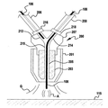
이제 도 2를 참조하면, 아크(A)가 소모품(108)과 공작물(115) 사이에 발생되는 용접 작업 중의 토치의 개략적인 단면도가 도시된다. 일반적으로, 토치(200)의 구현예들은 공작물에 소모품 및/또는 보호 가스를 전달하는 데에 사용되는 주지의 토치들과 유사하게 구성되며 작동된다. 이하에 논의되는 상세를 제외하면, 대부분의 작동 및 구성이 주지의 토치들과 유사하다. 토치(200)는 작업 영역으로 보호 가스(G)와 같은 가스를 안내하는 노즐(201)을 구비한다. 노즐(201)은 적절한 가스 전달을 제공하기 위해 주지의 노즐 구성들과 유사하게 구성될 수 있다. 토치 팁(203)이 노즐 내에 위치한다. 토치 팁(203)은 전원(101)에 전기적으로 결합되고, 전류가 토치 팁(203)의 스로트(205)를 통과함에 따라, 전류가 토치 팁을 통해 소모품(106/108)에 공급될 수 있다. 일부 응용들에서, 팁(203)이 작업에 소모품(106/108)을 간단히 전달하는 데에 사용됨에 따라, 팁(203)에 전류를 공급하는 것이 필요하지 않을 수도 있다. 이와 같은 작업은 GTAW를 포함할 수 있다. 어떤 경우든, 팁(203)은 주지의 팁 구성들과 유사하게 구성될 수 있다. 예컨대, 팁은 구리로 이루어지며 단일 스로트(205)를 구비할 수 있되, 소모품(106/108)이 이를 통과하여 공작물에 전달된다. 다중-와이어 팁 매니폴드(207)가 팁(203)의 상위 단부에 결합된다.Referring now to FIG. 2, there is shown a schematic cross-sectional view of a torch during a welding operation in which an arc A is generated between a consumable 108 and a
매니폴드(207)는 공통 스로트부(215)를 구비하되, 소모품들(106/108)이 이를 통과하여 팁(203)에 들어간다. 즉, 매니폴드(207)의 스로트(215)는 소모품이 매니폴드(215)로부터 팁(203)으로 용이하게 전달될 수 있도록 팁(203)의 스로트(205)와 정합된다. 매니폴드(207)는 또한 서로 및 스로트(215)와 연결되는 적어도 2개의 피더 스로트(213, 214)를 구비한다. 와이어 전달 케이블들(206, 208)이 연결되는 적어도 2개의 커넥터(216, 218)가 매니폴드(207)의 외표면 상에 있다. 케이블들(206/208)을 통해, 소모품들(106, 108)이 매니폴드(207)에 전달된다. 그러나, 도시된 바와 같이, 한 번에, 소모품들(106/108) 중 하나만이 공통 스로트(215)를 통해(203) 내로 전달된다. 2개의 소모품(106/108)만이 개시된 구현예들에 도시되지만, 본 발명의 다른 구현예들은 3개 이상의 소모품을 허용한다는 것을 주목해야 한다. 즉, 3개 이상의 소모품이 매니폴드(207)로 안내될 수 있고, 이들 각각은 공통 스로트(215)에 결합되는 독자적인 피더를 구비한다. 팁 및 매니폴드의 추가적인 논의가 이하에 기술된다.The manifold 207 has a
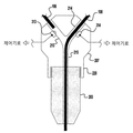
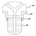
도 3은 본 발명의 예시적인 구현예의 단면도를 도시한다. 도시된 바와 같이, 매니폴드(207)는 팁(203)에 결합될 수 있도록 매니폴드(207)의 원위 단부 상에 연결부(220)를 구비한다. 도시된 구현예에서, 연결은 나사산식 연결일 수 있다. 그러나, 압입 등과 같은 다른 연결 방법이 사용될 수 있다. 또한, 다른 예시적인 구현예들에서, 팁 및 매니폴드는 일체형 구조일 수 있고, 도시된 바와 같이 별개의 부품들로 형성될 필요가 없다. 게다가, 매니폴드가 일반적으로 일체형 부품으로 도시되지만, 다른 구현예들에서는, 매니폴드(207)가 2개의 절반부와 같은 복수의 부품으로 이루어질 수 있다. 즉, 매니폴드(207)를 별개의 부품들로 제조한 후, 볼트 또는 체결구 또는 이와 유사한 것으로 서로 고정하는 것이 더 용이할 수 있다. 이와 같은 구성은 본 발명의 정신 또는 범주를 벗어나지 않는다.Figure 3 shows a cross-sectional view of an exemplary embodiment of the present invention. As shown, the manifold 207 has a
도 3에 도시된 바와 같이, 일부 예시적인 구현예들에서, 매니폴드는 각각의 피더 스로트들(213, 214) 내의 소모품들(106, 108)의 존재를 검출하는 데에 사용되는 센서들(313, 314)을 포함한다. 센서들은 시스템(100)의 제어기(103)가 소모품이 각각의 스로트들 내에 존재하는지 판단할 수 있도록 제어기에 전기적으로 결합된다. 이는 제어기(103)가 한 번에 팁을 통해 하나의 소모품만을 유지하도록 보장한다. 이러한 작동은 이하에 더 상세히 논의될 것이다. 센서들(313/314)은 피더 스로트들(213, 214) 내의 소모품의 존재를 검출할 수 있는 임의의 유형의 센서일 수 있다. 도 3의 센서들은, 압력 스위치와 같은, 각각의 소모품(106/108)이 각각의 스로트 내에 존재하는지 판단하기 위해 이와 접촉하는 접촉식 센서이다. 그러나, 접촉식 스위치들이 사용되는 한, 이들은 매니폴드를 통한 소모품들의 이동을 실질적으로 방해하지 않는 유형이어야 한다. 다른 예시적인 구현예들에서, 센서들은 광학, 자기 등과 같은 다른 유형의 센서들일 수 있다. 어떤 경우든, 센서들(313/314)은 소모품의 존재를 검출할 수 있고/있거나 소모품이 스위치(313/314) 상류의 위치로 후퇴한 시점을 검출할 수 있는 유형이어야 한다.As shown in Figure 3, in some exemplary embodiments, the manifold includes sensors (not shown) used to detect the presence of consumables 106,108 in each of the feeder lots 213,214 313, 314). The sensors are electrically coupled to the controller so that the
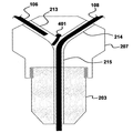
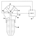
도 4a는 매니폴드(207)가 밸브 구조(401)를 포함하는 본 발명의 다른 예시적인 구현예를 도시하되, 이는 피더 스로트들(213/214)이 메인 스로트(215)를 형성하기 위해 수렴되는 지점과 가까운 위치에서 매니폴드(207)에 피벗 가능하게 결합된다. 이러한 밸브 구조(401)는 임의의 원하는 형상 또는 구성을 가질 수 있고, 밸브 구조(401)로 하여금 스로트들 내에서 피벗할 수 있게 하는 임의의 방식으로 매니폴드에 장착될 수 있다. 밸브 구조(401)는 상이한 피더 스로트로부터의 소모품이 메인 스로트(215) 내에 존재할 때 다른 피더 스로트를 차단하는 설계를 가진다. 예컨대, 도 4a에 도시된 바와 같이, 소모품(108)이 메인 스로트(215) 및 팁(207)에 삽입된다. 이 때문에, 밸브 구조(401)는 메인 스로트(215)로부터 피더 스로트를 폐쇄하기 위해 편향된다. 그러므로, 소모품(106)은 메인 스로트(215)로부터 물리적으로 차단되고, 그에 따라 소모품(106)이 우발적으로 전진할지라도, 이는 소모품(108)이 충분히 인출되는 시점까지 메인 스로트로부터 물리적으로 차단될 것이다. 밸브 구조(401)가 소모품의 우발적인 삽입을 방지하기 위해 메인 스로트를 물리적으로 차단할 정도로 견고해야 하지만, 이는 또한 소모품의 적절한 전진을 방해하거나 소모품의 표면에 자국이나 흠집을 남기지 않는 형상 및 구성이어야 한다. 예컨대, 밸브 구조(401)는 경질 플라스틱 재료로 이루어질 수 있다. 또한, 일부 구현예들에서 밸브 구조(401)의 이동이 소모품들에 의해 용이해질 수 있지만(즉, 수동 제어), 다른 예시적인 구현예들에서는 밸브(401)가 솔레노이드 또는 액추에이터, 또는 유사한 유형의 모션 제어 메커니즘에 의해 제어될 수 있다. 수동 시스템에서는, 피더 스로트로부터 메인 스로트로의 소모품의 간단한 움직임이 밸브(401)로 하여금 이동하여 다른 피더 채널을 차단하게 하는 반면, 액추에이터가 사용되는 구현예들에서는, 제어기(103)가 밸브(401)의 작동을 제어할 수 있고, 밸브의 제어에 도움이 되도록 센서들(313/314)로부터의 정보를 사용할 수 있다.Figure 4a illustrates another exemplary embodiment of the present invention in which the
다른 예시적인 구현예들에서, 도 4b에 일반적으로 도시된 바와 같이, 밸브(401)는 피더 스로트들(213/214)의 각각의 내표면 상의 2개의 전기 접점(403) 중 하나와 맞물리는 스위치용 접점의 역할을 할 수 있고, 그에 따라 어떤 회로 경로가 폐쇄되는지에 기초하여, 제어기(103)는 각각의 소모품들의 상태를 각각 판단할 수 있다. 예컨대, 도 4에 도시된 바와 같이, 소모품(108)이 토치(200) 내에 완전히 삽입되면, 밸브(401)의 원위 선단은 피더 스로트(213)의 내표면 상의 접점부(403)와 접촉하고, 이는 소모품(108)이 토치(200)를 통해 공급되고 소모품(106)이 충분히 후퇴된 것을 제어기(103)에 알린다. 소모품(106)이 메인 스로트(215)에 삽입되고 소모품(108)이 후퇴되는 경우 유사한 제어 방법이 적용될 것이다. 추가 구현예들에서, 밸브(401)는 제어 회로가 개방되도록 임의의 측벽과 신호 접촉하지 않는 중립 위치를 가질 것이다. 이는 밸브(401)가 임의의 측벽과 맞물리지 않으므로 어떤 소모품도 메인 스로트(215) 내에 있지 않다는 것을 제어기에 알리는데, 이는 제어기(103)로 하여금 다른 전극을 후퇴시킬 필요 없이 원하는 전극을 전진시킬 수 있게 한다. 본 발명의 구현예들은 공급 스로트들(213/214)의 공동 내에 접점들(403)을 구비하는 것에 제한되는 것이 아니라, 본 발명의 정신 또는 범주를 벗어남 없이 메인 스로트(215)의 각각의 측벽 상에 위치할 수도 있다는 것을 주목해야 한다.In other exemplary embodiments, as shown generally in FIG. 4B, the
도 5는 유전체 스페이서(207')가 매니폴드(207)와 팁(203) 사이에 위치하는 본 발명의 다른 예시적인 구현예를 도시한다. 스페이서(207')는 격리가 요구되는 토치 구성을 위해 팁(203)과 매니폴드(207)를 전기적으로 격리시키는 데에 사용된다. 게다가, 다른 예시적인 구현예들에서, 매니폴드(207) 자체가 유전체 재료로 이루어질 수 있다. 도 5의 구현예에서, 매니폴드(207)는 유전체 스페이서(207')에 압입되고, 이는 이후 원위 나사산부(220)를 통해 팁(203)에 고정된다.FIG. 5 illustrates another exemplary embodiment of the present invention in which dielectric spacer 207 'is located between
도 6은 본 발명의 예시적인 구현예에 따른 시스템(100)의 작동을 위한 흐름도이다. 이러한 작동은 와이어 피더들(105/107) 및/또는 시스템(100)의 작동을 제어하는 데에 사용되는 제어기(103) 또는 임의의 다른 제어 시스템 또는 장치에 의해 실행될 수 있다. 게다가, 도 6의 흐름도는 예시적인 시스템(100)이 작동될 수 있는 일례이므로, 본 발명의 정신 또는 범주를 벗어남 없이 다른 제어 방법들이 사용될 수 있다.6 is a flow chart for operation of
원하는 작업이 시작되어야 할 때, 사용자 또는 제어기 또는 제어 시스템은 선택된 작업을 위해 원하는 소모품을 결정할 것이다(단계 601). 예컨대, 사용자 또는 로봇식 제어 시스템은 제1 소모품(예컨대, 연강)이 사용되어야 한다고 결정할 것이다. 이후, 제어기(103)는 원하는 소모품이 토치(200)를 통해 전진하는지 판단할 것이다(단계 603). 이는 전술한 바와 같이 센서의 사용을 비롯한 다수의 방식으로 이행될 수 있다. 이는 또한 이전 작업으로부터의 데이터를 이용함으로써 제어기(103)에 의해 판단될 수 있다. 즉, 원하는 소모품이 이전 작업으로부터 사용된 최종 소모품이었다면, 필요 시 제어기(103)는 원하는 소모품이 토치(200) 내에 남아있다고 판단할 수 있다. 도시되지 않지만, 제어기(103)는 원하는 소모품이 주어진 작업을 위해 원하는 거리만큼 팁(203)을 지나 연장되도록 보장하기 위해, 임의의 주지의 제어 방법을 사용할 수 있음은 물론이다. 도시된 바와 같이, 원하는 소모품이 토치(200)를 통해 전진하면, 필요 시 작업을 시작할 수 있다(단계 610). 그러나, 원하는 소모품이 전진하지 않으면, 다른 소모품이 전진하거나 토치(200) 내에 남아있는지에 관한 판단이 이루어진다(단계 605). (예컨대, 상기에 논의된 센서들을 통해) 다른 소모품이 토치(200) 내에 존재하는 것으로 검출되지 않으면, 제어기(103)는 원하는 소모품을 원하는 스틱아웃(stickout)까지 전진하게 할 것이며, 이후 작업을 시작할 수 있다(단계 610).When the desired job is to be started, the user or controller or control system will determine the desired consumable for the selected job (step 601). For example, the user or robotic control system will determine that a first consumable (e.g., mild steel) should be used. Thereafter, the
그러나, 다른 소모품이 전진하거나 토치(200)(또는 메인 스로트(215)) 내에 있는 것으로 검출되면, 제어기(103)는 소모품을 후퇴하게 할 것이다(단계 609). 이후, 제어기(103)는 적절한 와이어 피더로 하여금 다른 소모품을 후퇴시키게 하고, 다른 소모품이 충분히 인출되었다고 판단될 때까지(예컨대, 센서에 의해 더 이상 감지되지 않을 때까지) 그 존재를 계속 검출할 것이다(단계 611). 다른 소모품이 후퇴한 후에, 적절한 소모품이 전진할 것이며(607), 작업을 시작할 수 있다(610).However, if another consumable is detected to be moving forward or within the torch 200 (or the main throat 215), the
본 발명은 특히 예시적인 구현예들을 참조하여 도시되고 설명되었지만, 본 발명은 이러한 구현예들에 제한되지 않는다. 당업자들은 후술하는 청구범위에 의해 정의된 바와 같이 본 발명의 정신 및 범주를 벗어남 없이 형태 및 상세의 다양한 변경이 이루어질 수 있음을 이해할 것이다.While the invention has been particularly shown and described with reference to exemplary embodiments, the invention is not limited to these embodiments. It will be understood by those skilled in the art that various changes in form and detail may be made therein without departing from the spirit and scope of the invention as defined by the following claims.
100
시스템
101
전원
103
제어기
105
와이어 피더
106
소모품
107
와이어 피더
108
소모품
109
가스 유동 매니폴드
111
가스 공급원
113
가스 공급원
115
공작물
190
모션 제어 장치
200
토치
201
노즐
203
토치 팁
205
스로트
206
와이어 전달 케이블
207
매니폴드
207'
유전체 스페이서
208
와이어 전달 케이블
213
스로트
214
스로트
215
스로트
216
커넥터
218
커넥터
220
연결부
313
센서
314
센서
401
밸브 구조
403
전기 접점
601
단계
603
단계
607
단계
605
단계
609
단계
610
단계
611
단계
A
아크100 system
101 Power Supply
103 controller
105 wire feeder
106 Consumables
107 Wire feeder
108 Consumables
109 Gas Flow Manifold
111 gas supply source
113 gas supply source
115 Workpiece
190 Motion control device
200 torches
201 nozzle
203 Torch tips
205 throat
206 Wire Transfer Cable
207 Manifold
207 'dielectric spacer
208 Wire Transfer Cable
213 throat
214 throat
215 throat
216 connector
218 connector
220 connection
313 sensor
314 sensor
401 valve structure
403 Electrical contacts
A arc
Claims (15)
상기 매니폴드부에 결합되며 접촉 팁 스로트를 구비한 접촉 팁으로, 상기 접촉 팁 스로트로의 유입구가 상기 매니폴드부 단일 출구 스로트와 정렬되는 접촉 팁을 포함하고,
상기 매니폴드 단일 출구 스로트 및 상기 접촉 팁 스로트 각각은 상기 제1 및 제2 소모품(106, 108) 중 하나만이 한 번에 상기 각각의 스로트들 내에 존재할 수 있도록 구성되는, 소모품 전달 토치.Wherein the first and second consumable inlet throats are separated from each other by a manifold portion having at least a first and a second consumable inlet throat and a single outlet throat to which the first and second inlet throats are respectively coupled, Wherein the first inlet throat is configured to receive a first consumable (106, 108), the second inlet throat comprises a manifold portion configured to receive a second consumable (106, 108), and
A contact tip coupled to the manifold portion and having a contact tip throat, the inlet to the contact tip throat comprising a contact tip aligned with the manifold portion single exit throat,
Wherein the manifold single outlet throat and the contact tip throat, respectively, are configured such that only one of the first and second consumables (106, 108) can reside within the respective throats at a time.
상기 매니폴드부는 상기 제1 및 제2 소모품(106, 108) 중 하나가 상기 매니폴드부의 단일 출구 스로트 내에 존재할 때 제1 및 제2 소모품(106, 108) 중 다른 하나의 전진을 방지하는 밸브 구조(401)를 추가로 포함하는, 소모품 전달 토치.The method according to claim 1,
The manifold portion includes a valve for preventing advancement of the other of the first and second consumables (106, 108) when one of the first and second consumables (106, 108) is within the single outlet throat of the manifold portion ≪ / RTI > further comprising a structure (401).
상기 밸브 구조(401)는, 상기 제1 소모품(106, 108)이 상기 단일 출구 스로트 내에 존재할 때 상기 밸브 구조(401)가 상기 제2 소모품(106, 108)이 상기 단일 출구 스로트 내로 전진하는 것을 방지하고, 상기 제2 소모품(106, 108)이 상기 단일 출구 스로트 내에 존재할 때 상기 밸브 구조(401)가 상기 제1 소모품이 상기 단일 출구 스로트 내로 전진하는 것을 방지하도록, 상기 제1 및 제2 소모품(106, 108) 각각에 의해 제어되고/제어되거나,
상기 밸브 구조(401)는 상기 제1 및 제2 소모품(106, 108) 중 하나만이 주어진 시점에 상기 단일 출구 스로트 내로 전진할 수 있도록 제어기에 의해 제어되는, 소모품 전달 토치.3. The method according to claim 1 or 2,
The valve structure (401) is configured such that when the first supply (106,108) is in the single outlet throat, the valve structure (401) causes the second supply (106,108) to advance into the single outlet throat And prevents the valve structure (401) from advancing the first supply into the single outlet throat when the second supply (106, 108) is within the single outlet throttle, And second consumables 106 and 108, respectively,
Wherein the valve structure (401) is controlled by a controller so that only one of the first and second consumables (106, 108) can advance into the single outlet throat at a given time.
상기 매니폴드부는 유전체 스페이서(207)를 통해 상기 접촉 팁에 결합되는, 소모품 전달 토치.4. The method according to any one of claims 1 to 3,
Wherein the manifold portion is coupled to the contact tip via a dielectric spacer (207).
상기 단일 출구 스로트는 상기 제1 및 제2 소모품(106, 108) 중 하나만이 한 번에 상기 단일 출구 스로트 내에 존재할 수 있도록 구성되는, 소모품 전달 토치용 매니폴드.A manifold body portion having at least a first and a second supply inlet throat and a single outlet throat to which the first and second inlet throats are respectively coupled, the first and second consumable inlet throats being separated from each other , The first inlet throttle is configured to receive a first supply (106,108), and the second inlet throat includes a manifold body configured to receive a second consumable (106,108)
Wherein the single outlet throat is configured such that only one of the first and second consumables (106, 108) can be present in the single outlet throat at a time.
상기 제1 유입 스로트는 상기 제2 유입 스로트와 상이한 직경을 가지는, 소모품 전달 토치 또는 매니폴드.6. The method according to any one of claims 1 to 5,
Wherein the first inlet throat has a different diameter than the second inlet throat.
상기 제1 및 제2 유입 스로트 중 적어도 하나는 각각 상기 제1 및 제2 유입 스로트 내의 상기 제1 및 제2 소모품(106, 108)의 존재를 검출하는 센서를 포함하는, 소모품 전달 토치 또는 매니폴드.7. The method according to any one of claims 1 to 6,
Wherein at least one of the first and second inflow throats comprises a sensor for detecting the presence of the first and second consumables (106, 108) in the first and second inflow throats, respectively, Manifold.
상기 센서는 상기 제1 또는 제2 소모품(106, 108)의 존재를 검출하기 위해 이와 접촉하는, 소모품 전달 토치 또는 매니폴드.8. The method according to any one of claims 1 to 7,
Wherein the sensor is in contact therewith to detect the presence of the first or second consumables (106, 108).
상기 매니폴드 몸체부는 상기 제1 및 제2 소모품(106, 108) 중 하나가 상기 매니폴드부의 단일 출구 스로트 내에 존재할 때 제1 및 제2 소모품(106, 108) 중 다른 하나의 전진을 방지하는 밸브 구조(401)를 추가로 포함하는, 매니폴드.9. The method according to any one of claims 5 to 8,
The manifold body prevents advancement of the other of the first and second consumables (106, 108) when one of the first and second consumables (106, 108) is within a single outlet throat of the manifold portion Further comprising a valve structure (401).
상기 밸브 구조(401)는, 상기 제1 소모품(106, 108)이 상기 단일 출구 스로트 내에 존재할 때 상기 밸브 구조가 상기 제2 소모품(106, 108)이 상기 단일 출구 스로트 내로 전진하는 것을 방지하고, 상기 제2 소모품(106, 108)이 상기 단일 출구 스로트 내에 존재할 때 상기 밸브 구조가 상기 제1 소모품(106, 108)이 상기 단일 출구 스로트 내로 전진하는 것을 방지하도록, 상기 제1 및 제2 소모품(106, 108) 각각에 의해 제어되는, 매니폴드.10. The method according to any one of claims 5 to 9,
The valve structure (401) is configured to prevent the valve structure from advancing the second supply (106,108) into the single outlet throat when the first supply (106,108) is within the single outlet throttle And wherein the valve structure prevents the first supply (106, 108) from advancing into the single outlet throttle when the second supply (106, 108) is in the single outlet throttle. (106, 108), respectively.
상기 밸브 구조(401)는 상기 제1 및 제2 소모품(106, 108) 중 하나만이 주어진 시점에 상기 단일 출구 스로트 내로 전진할 수 있도록 제어기에 의해 제어되는, 매니폴드.11. The method according to any one of claims 5 to 10,
The valve structure (401) is controlled by the controller so that only one of the first and second consumables (106, 108) can advance into the single outlet throat at a given point in time.
상기 제1 소모품을 상기 매니폴드부로 안내하는 제1 와이어 공급 시스템,
상기 제2 소모품을 상기 매니폴드부로 안내하는 제2 와이어 공급 시스템, 및
상기 제1 및 제2 소모품(106, 108) 중 하나만이 임의의 주어진 시점에 상기 단일 출구 스로트 내에 존재하도록 상기 제1 및 제2 와이어 공급 시스템을 각각 제어하는 제어기를 포함하는, 소모품 전달 시스템.Wherein the first and second consumable inlet throats are separated from each other by a manifold portion having at least a first and a second consumable inlet throat and a single outlet throat to which the first and second inlet throats are respectively coupled, Wherein the first inlet throttle is configured to receive a first consumable product (106,108), the second inlet throat includes a manifold portion configured to receive a second consumable product (106,108), and a manifold portion coupled to the manifold portion And a contact tip having a contact tip throat, the inlet to the contact tip throat comprising a contact tip aligned with the manifold single-outlet throat, the manifold single exit throat and the contact tip throat Each of which is configured such that only one of said first and second consumables (106, 108) can reside within said respective throats at a time,
A first wire feeding system for guiding the first consumable item to the manifold part,
A second wire supply system for guiding the second consumable item to the manifold part, and
And a controller for controlling said first and second wire supply systems, respectively, such that only one of said first and second consumables (106, 108) is present in said single outlet throat at any given point in time.
상기 제1 및 제2 유입 스로트 중 적어도 하나는 각각 상기 제1 및 제2 유입 스로트 내의 상기 제1 및 제2 소모품(106, 108)의 존재를 검출하는 센서를 포함하는, 시스템.13. The method of claim 12,
Wherein at least one of the first and second inflow throats comprises a sensor for detecting the presence of the first and second consumables (106, 108) in the first and second inflow throats, respectively.
상기 매니폴드부는 상기 제1 및 제2 소모품(106, 108) 중 하나가 상기 매니폴드부의 단일 출구 스로트 내에 존재할 때 제1 및 제2 소모품(106, 108) 중 다른 하나의 전진을 방지하는 밸브 구조(401)를 추가로 포함하는, 시스템.The method according to claim 12 or 13,
The manifold portion includes a valve for preventing advancement of the other of the first and second consumables (106, 108) when one of the first and second consumables (106, 108) is within the single outlet throat of the manifold portion ≪ / RTI > further comprising a structure (401).
상기 밸브 구조(401)는 상기 제1 및 제2 소모품(106, 108) 중 하나만이 주어진 시점에 상기 단일 출구 스로트 내로 전진할 수 있도록 상기 제어기에 의해 제어되는, 시스템.15. The method according to any one of claims 12 to 14,
The valve structure (401) is controlled by the controller such that only one of the first and second consumables (106, 108) can advance into the single outlet throat at a given time.
Applications Claiming Priority (3)
| Application Number | Priority Date | Filing Date | Title |
|---|---|---|---|
| US14/470,459 US20160059341A1 (en) | 2014-08-27 | 2014-08-27 | Multi-consumable torch tip and systems and methods of using the same |
| US14/470,459 | 2014-08-27 | ||
| PCT/IB2015/001439 WO2016030739A1 (en) | 2014-08-27 | 2015-08-24 | Manifold for a multi-consumable delivery torch with two inlets and one outlet; consumable delivery torch and system |
Publications (1)
| Publication Number | Publication Date |
|---|---|
| KR20170046667A true KR20170046667A (en) | 2017-05-02 |
Family
ID=54427803
Family Applications (1)
| Application Number | Title | Priority Date | Filing Date |
|---|---|---|---|
| KR1020177005356A KR20170046667A (en) | 2014-08-27 | 2015-08-24 | Manifold for a multi-consumable delivery torch with two inlets and one outlet, consumable delivery torch and system |
Country Status (7)
| Country | Link |
|---|---|
| US (1) | US20160059341A1 (en) |
| EP (1) | EP3186026A1 (en) |
| JP (1) | JP2017530009A (en) |
| KR (1) | KR20170046667A (en) |
| CN (1) | CN106573327A (en) |
| BR (1) | BR112017003598A2 (en) |
| WO (1) | WO2016030739A1 (en) |
Families Citing this family (12)
| Publication number | Priority date | Publication date | Assignee | Title |
|---|---|---|---|---|
| EP3366404B1 (en) * | 2015-10-23 | 2020-09-16 | Panasonic Intellectual Property Management Co., Ltd. | Welding torch |
| US10537958B2 (en) | 2016-08-15 | 2020-01-21 | Illinois Tool Works Inc. | System and method for controlling shielding gas flow in a welding device |
| US11801569B2 (en) * | 2017-06-28 | 2023-10-31 | Esab Ab | Stopping an electroslag welding process |
| CN108115253A (en) * | 2017-12-20 | 2018-06-05 | 中建钢构武汉有限公司 | Steel structure node manufacture system and method |
| EP3546104B1 (en) * | 2018-03-28 | 2023-04-26 | Purem GmbH | Welding wire supply system |
| DE102018114754A1 (en) * | 2018-03-28 | 2019-10-02 | Eberspächer Exhaust Technology GmbH & Co. KG | Schweißdrahtzuführsystem |
| PL3959029T3 (en) * | 2019-04-24 | 2022-11-07 | Alexander Binzel Schweisstechnik Gmbh & Co. Kg | Welding device and method for operating a welding device |
| US20210101221A1 (en) * | 2019-10-02 | 2021-04-08 | Lincoln Global, Inc. | Shielding gas customized welding apparatus and method |
| US20210283708A1 (en) * | 2020-03-11 | 2021-09-16 | Illinois Tool Works Inc. | Smart regulators for welding-type systems |
| US20210283724A1 (en) * | 2020-03-11 | 2021-09-16 | Illinois Tool Works Inc. | Smart manifolds for welding-type systems |
| US11938574B2 (en) | 2021-01-22 | 2024-03-26 | Illinois Tool Works Inc. | Gas surge prevention using improved flow regulators in welding-type systems |
| US11801482B2 (en) | 2021-02-17 | 2023-10-31 | Illinois Tool Works Inc. | Mixing fluids in welding-type equipment |
Family Cites Families (10)
| Publication number | Priority date | Publication date | Assignee | Title |
|---|---|---|---|---|
| DE1948633A1 (en) * | 1969-09-26 | 1971-04-01 | Zinser Textilmaschinen Gmbh | Twisting or spinning machine |
| JPS56168967A (en) * | 1980-05-30 | 1981-12-25 | Mitsubishi Electric Corp | Wire feeder for welding |
| JPH01170593A (en) * | 1987-12-25 | 1989-07-05 | Kawasaki Steel Corp | Welding wire feeding device |
| US5302805A (en) * | 1993-05-27 | 1994-04-12 | The United States Of America As Represented By The Administrator Of The National Aeronautics And Space Administration | Welding wire pressure sensor assembly |
| DE10204818C2 (en) * | 2002-02-06 | 2003-11-27 | Eurotope Entwicklungsgesellsch | Device and method for loading implantation needles with radiation sources from radiation source chains for interstitial brachytherapy of tissue |
| JP2006198628A (en) * | 2005-01-18 | 2006-08-03 | Fanuc Ltd | Arc welding equipment, and arc robot system |
| US7335854B2 (en) * | 2005-03-11 | 2008-02-26 | Illinois Tool Works Inc. | Method and system of determining wire feed speed |
| JP2006281284A (en) * | 2005-04-01 | 2006-10-19 | Sango Co Ltd | Welding equipment |
| AU2011384252B2 (en) * | 2011-12-23 | 2015-05-28 | Esab Ab | An arc welding head and a welding arrangement |
| US9821402B2 (en) * | 2012-03-27 | 2017-11-21 | Illinois Tool Works Inc. | System and method for submerged arc welding |
-
2014
- 2014-08-27 US US14/470,459 patent/US20160059341A1/en not_active Abandoned
-
2015
- 2015-08-24 BR BR112017003598A patent/BR112017003598A2/en not_active Application Discontinuation
- 2015-08-24 JP JP2017511165A patent/JP2017530009A/en active Pending
- 2015-08-24 EP EP15790646.2A patent/EP3186026A1/en not_active Withdrawn
- 2015-08-24 WO PCT/IB2015/001439 patent/WO2016030739A1/en active Application Filing
- 2015-08-24 KR KR1020177005356A patent/KR20170046667A/en unknown
- 2015-08-24 CN CN201580042861.9A patent/CN106573327A/en active Pending
Also Published As
| Publication number | Publication date |
|---|---|
| EP3186026A1 (en) | 2017-07-05 |
| JP2017530009A (en) | 2017-10-12 |
| US20160059341A1 (en) | 2016-03-03 |
| BR112017003598A2 (en) | 2017-12-12 |
| WO2016030739A1 (en) | 2016-03-03 |
| CN106573327A (en) | 2017-04-19 |
Similar Documents
| Publication | Publication Date | Title |
|---|---|---|
| KR20170046667A (en) | Manifold for a multi-consumable delivery torch with two inlets and one outlet, consumable delivery torch and system | |
| KR102152482B1 (en) | Voltage sensing wire feeder with weld procedure memories | |
| US8581146B2 (en) | Automatic wire feeding system | |
| JP5021643B2 (en) | Configurable dual process welding head and method for configuring the same | |
| JP4892341B2 (en) | Welding torch including drive unit and wire buffer storage | |
| US9486874B2 (en) | Control assembly for a welding gun | |
| US11524354B2 (en) | Systems, methods, and apparatus to control weld current in a preheating system | |
| US20140263253A1 (en) | Welding diffuser insert | |
| US9527155B2 (en) | Welding diffuser with debris removal | |
| CN111386167B (en) | Contact tip having a thread and a head for effecting loosening by the thread | |
| WO2007144999A1 (en) | Tandem arc welding device | |
| EP2988901B1 (en) | Hybrid thread for welding gun neck | |
| EP3366404B1 (en) | Welding torch | |
| US10322464B2 (en) | Welding system and method of control | |
| US10888946B2 (en) | TIG gun power pin for welding device or system and multi-process welder with a single gas flow path | |
| JP4615779B2 (en) | Tandem arc automatic welding system | |
| JP6434320B2 (en) | Thermal spray gun and thermal spray apparatus provided with the same | |
| CN111315524A (en) | Welding torch having two contacts and multiple liquid cooled assemblies for conducting current to the contacts | |
| EP4353390A1 (en) | Welding system, welding power supply and welding wire feeder employing dedicated power and communication cable and connections circuitries | |
| US20230398622A1 (en) | Systems and methods for weld process selection and isolation from a voltage sensing wire feeder |