KR20170041475A - Feeding Roller Assembly and Feeding Apparatus using the Same - Google Patents
Feeding Roller Assembly and Feeding Apparatus using the Same Download PDFInfo
- Publication number
- KR20170041475A KR20170041475A KR1020150140940A KR20150140940A KR20170041475A KR 20170041475 A KR20170041475 A KR 20170041475A KR 1020150140940 A KR1020150140940 A KR 1020150140940A KR 20150140940 A KR20150140940 A KR 20150140940A KR 20170041475 A KR20170041475 A KR 20170041475A
- Authority
- KR
- South Korea
- Prior art keywords
- skeleton frame
- molded body
- conveying
- coupled
- drive shaft
- Prior art date
Links
Images


Classifications
-
- B—PERFORMING OPERATIONS; TRANSPORTING
- B65—CONVEYING; PACKING; STORING; HANDLING THIN OR FILAMENTARY MATERIAL
- B65G—TRANSPORT OR STORAGE DEVICES, e.g. CONVEYORS FOR LOADING OR TIPPING, SHOP CONVEYOR SYSTEMS OR PNEUMATIC TUBE CONVEYORS
- B65G39/00—Rollers, e.g. drive rollers, or arrangements thereof incorporated in roller-ways or other types of mechanical conveyors
- B65G39/02—Adaptations of individual rollers and supports therefor
-
- B—PERFORMING OPERATIONS; TRANSPORTING
- B65—CONVEYING; PACKING; STORING; HANDLING THIN OR FILAMENTARY MATERIAL
- B65G—TRANSPORT OR STORAGE DEVICES, e.g. CONVEYORS FOR LOADING OR TIPPING, SHOP CONVEYOR SYSTEMS OR PNEUMATIC TUBE CONVEYORS
- B65G13/00—Roller-ways
-
- B—PERFORMING OPERATIONS; TRANSPORTING
- B65—CONVEYING; PACKING; STORING; HANDLING THIN OR FILAMENTARY MATERIAL
- B65G—TRANSPORT OR STORAGE DEVICES, e.g. CONVEYORS FOR LOADING OR TIPPING, SHOP CONVEYOR SYSTEMS OR PNEUMATIC TUBE CONVEYORS
- B65G13/00—Roller-ways
- B65G13/11—Roller frames
-
- B—PERFORMING OPERATIONS; TRANSPORTING
- B65—CONVEYING; PACKING; STORING; HANDLING THIN OR FILAMENTARY MATERIAL
- B65G—TRANSPORT OR STORAGE DEVICES, e.g. CONVEYORS FOR LOADING OR TIPPING, SHOP CONVEYOR SYSTEMS OR PNEUMATIC TUBE CONVEYORS
- B65G39/00—Rollers, e.g. drive rollers, or arrangements thereof incorporated in roller-ways or other types of mechanical conveyors
- B65G39/10—Arrangements of rollers
Abstract
Thereby providing a conveying roller assembly. A conveying roller assembly according to an embodiment of the present invention is a conveying roller assembly mounted on a rotary drive shaft and having at least two divided rollers coupled to each other so as to convey the conveyed object in one direction, And a joint block extending from the skeleton frame and exposed to protrude from at least one side of the molded body, wherein the joint of the skeleton frame and the skeleton frame is integrally formed with the skeleton frame, The at least two division rollers are coupled to the rotary drive shaft by a circular roller as the engagement blocks of the corresponding conveying rollers and the block are coupled to each other by the fastening means.
Description
BACKGROUND OF THE INVENTION 1. Field of the Invention The present invention relates to a conveying roller assembly and a conveying device using the conveying roller assembly. More particularly, the present invention relates to a conveying roller and a conveying device using the conveying roller.
In general, a plate-like substrate such as a glass substrate is applied to various products and can be applied to flat panel display devices such as an LCD (Liquid Crystal Display) and an OLED (Organic Light Emitting Diode).
The substrate used in such a device is produced as a final product through various semiconductor manufacturing processes, and is transferred to a post-process by a conveying roller that is rotationally driven to perform each semiconductor manufacturing process.
That is, the conveying roller, on which the substrate is lifted to convey the substrate to be conveyed, to a post-process, is assembled at a predetermined interval to a rotary driving shaft driven to rotate by a driving source such as a driving motor, The substrate on which the outer circumferential surface and the lower surface of the substrate are in contact with each other is conveyed in one direction by a frictional force generated therebetween.
The outer periphery of the conveying roller is provided with a frictional force at the time of conveyance of the substrate to prevent slippage between the conveying object and the substrate and to smoothly convey the substrate while preventing damage to the surface of the substrate. Can be installed.
Meanwhile, the conveying roller is assembled at a predetermined interval to the rotary drive shaft by a coupling method in which the rotary drive shaft is inserted through a shaft hole formed in the center of the body.
Accordingly, any one of the plurality of conveying rollers is damaged or worn and replaced with a new conveying roller, the other normal conveying rollers adjacent to the conveying roller as a replacement object must also be separated from the rotary driving shaft, and after the conveying roller replacing operation It is necessary to reassemble to the original position of the rotary drive shaft. Therefore, the workload of the worker is increased and the work time required for replacing the conveying roller becomes longer, so that it takes much time and the work stoppage time becomes long.
Further, since the conveying rollers on the rough disc surface are accompanied by hole machining for forming the shaft hole at the center of the roller body and cutting machining for machining the outer surface of the roller body formed with the shaft hole into a disk shape, Resulting in an increase in manufacturing cost due to processing.
Further, in order to increase the frictional force with the object to be conveyed, there is a problem that the work is cumbersome and the workload of the worker is increased because the operation of additionally assembling and assembling a separately manufactured O-ring is carried out on the outer surface of the conveying roller.
(Patent Document 1) KR10-2007-0048044 A
(Patent Document 2) KR10-2013-0133551 A
SUMMARY OF THE INVENTION Accordingly, the present invention has been made to solve the above-mentioned problems occurring in the prior art, and it is an object of the present invention to provide an image forming apparatus, And to provide a conveying device using the conveying roller assembly and a conveying device using the conveying roller assembly.
It is to be understood that both the foregoing general description and the following detailed description are exemplary and explanatory and are not restrictive of the invention, unless further departing from the spirit and scope of the invention as defined by the appended claims. It will be possible.
According to one aspect of the present invention, there is provided a conveying roller assembly mounted on a rotary drive shaft and having at least two dividing rollers coupled to each other so as to convey the conveying object in one direction, A molding body formed to integrate the skeleton frame therein, and a joint block extending from the skeleton frame and exposed to protrude from at least one side of the molding body, wherein the skeleton frame has an inner groove formed on one side corresponding to the rotation drive shaft, And the at least two split rollers are coupled to the rotary drive shaft by a circular roller as the engagement block of the conveying roller and the corresponding engagement block of the other conveyance roller are coupled to each other by the fastening means.
In this case, the fastening means may include a coupling hole formed in the coupling block, and a coupling member passing through the coupling hole of the coupling block and coupled to the coupling hole of the other coupling block.
In this case, the skeleton frame includes a plurality of through-holes, and the plurality of through-holes may be formed to fill the formed body.
At this time, the skeleton frame may include a plurality of embedding grooves formed at one side or both sides of the body and recessed at a predetermined depth to embed the molded body.
At this time, the formed body may have an inner circumferential groove which is in contact with the rotary drive shaft on one side corresponding to the inner circumferential groove.
In this case, the inner circumferential grooves may include a plurality of rows of grooves formed to be continuously recessed along the inner circumferential direction.
At this time, a contact portion is formed on an outer edge of the molded body which is in contact with the conveying object, and the contact portion may include a toothed groove formed at an outer edge of the formed body with a predetermined pitch in the circumferential direction.
At this time, the contact portion may include a drain groove formed in the outer edge of the molded body in a circumferential direction.
In this case, the contact portion may include a drain groove recessed between a pair of right and left tooth grooves formed at an outer edge of the molded body at a predetermined pitch in a circumferential direction.
At this time, the coupling block may be provided as an integral block extending from the skeleton frame.
At this time, the coupling block may be provided as a coupling and coupling block that forms a fitting groove to be fitted into the skeleton frame.
At this time, the molded body may be coupled to the skeletal frame by injection molding.
In this case, the skeleton frame may be made of a metal material, and the molded body may be made of a resin material.
According to another aspect of the present invention, there is provided a conveyance apparatus for conveying a conveyed object placed on a conveying roller assembly, the conveying roller assembly being provided with a driving source for rotationally driving a rotary driving shaft having a plurality of conveying roller assemblies.
The present invention as described above has the following effects.
(1) A plurality of division rollers are arranged so that the inner circumferential groove is in contact with the rotary drive shaft, and then a circular conveying roller assembly is assembled by a fastening member fastened to the engagement hole of the engagement block facing each other, Assembly and replacement of damaged or worn conveyor roller assemblies can be performed more easily and quickly than single-piece conveyor rollers, thereby reducing the amount of time required for work, While the workload of the operator can be reduced.
(2) The produced skeleton frame is disposed in the mold, and the formed body is integrated by the insert injection molding process so as to be integrated with the skeleton frame, whereby the conveying roller assembly can be manufactured without the need of machining to cut through the shaft hole or to cut the outer surface Therefore, it is possible to reduce the overall weight by reducing the amount of material used by optimizing the design of the mold, and it is possible to reduce the cost of manufacturing the conveying roller, thereby enhancing the price competitiveness.
(3) Since the surface of the object to be conveyed can be reduced while the frictional force that is formed on the outer edge of the molded body and in contact with the object to be conveyed is increased, the work efficiency of transferring the object to the post- And it is possible to reduce the surface defects of the object to be conveyed, thereby enhancing the reliability.
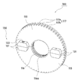
FIG. 1 is an assembled state of a conveying roller assembly according to a preferred embodiment of the present invention assembled with a rotary drive shaft.
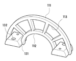
2 is an overall perspective view showing a conveying roller assembly according to a preferred embodiment of the present invention.
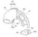
3 is an exploded perspective view showing a conveying roller assembly according to a preferred embodiment of the present invention.
4A and 4B are detailed views illustrating a skeleton frame employed in a conveying roller assembly according to a preferred embodiment of the present invention.
5A and 5B are cross-sectional perspective views illustrating a connection relationship between a skeleton frame, a molded body, and a coupling portion in a conveying roller assembly according to a preferred embodiment of the present invention.
6 is a perspective view showing another embodiment of a conveying roller assembly according to a preferred embodiment of the present invention.
7 is a schematic view showing a conveying apparatus using a conveying roller assembly according to a preferred embodiment of the present invention.
DETAILED DESCRIPTION OF THE PREFERRED EMBODIMENTS Hereinafter, preferred embodiments of the present invention will be described in detail with reference to the accompanying drawings. In the following description, a detailed description of known functions and configurations incorporated herein will be omitted when it may obscure the subject matter of the present invention.
The same reference numerals are used for portions having similar functions and functions throughout the drawings.
In addition, in the entire specification, when a part is referred to as being 'connected' to another part, it may be referred to as 'indirectly connected' not only with 'directly connected' . Also, to include an element does not exclude other elements unless specifically stated otherwise, but may also include other elements.
1 to 4B, a
The dividing
The
The molded
A
Here, the molded
The
Accordingly, the dividing
In addition, it is possible to prevent surface damage of a conveyed object contacting a molded body of a soft material, which is relatively soft compared with a
5A, the
A plurality of rows of
The
The
At this time, the
The
The width of the
The
At least two split
As shown in FIG. 5A, the
The
The
It will be easily understood by those skilled in the art that adjacent joint blocks in this embodiment can be joined by various fastening means not shown.
2, the two conveying
7, the conveying
It will be apparent to those skilled in the art that various modifications and variations can be made in the present invention without departing from the spirit or scope of the inventions. It will be apparent to those of ordinary skill in the art.
110: split roller
111: skeletal frame
112: inner groove
113a: Through hole
113a: buried groove
115: molded article
116: inner circumference groove
117:
117a: serration groove
117b: drainage groove
130:
131: Coupling block
132: coupling ball
133: fastening member
Claims (14)
The split roller
A skeleton frame having an inner groove formed on one side corresponding to the rotary drive shaft,
A molded body that is molded to integrate the skeletal frame therein
And a joint block extending from the skeleton frame and exposed to protrude from at least one side of the molded body,
Wherein the at least two division rollers are coupled to the rotary drive shaft as circular rollers as the engagement blocks of the conveying rollers and the corresponding engagement blocks of the other conveyance rollers are coupled to each other by the fastening means.
The fastening means
A coupling hole formed in the coupling block and
And a fastening member passing through the fastening hole of the fastening block and coupled to the fastening hole of another fastening block.
Wherein the skeleton frame has a plurality of through-holes, and the plurality of through-holes are formed to fill the formed body.
Wherein the skeleton frame includes a plurality of embedding grooves formed at one side or both sides of the body to be recessed at a predetermined depth to embed the molded body.
Wherein the molded body has an inner circumferential groove formed on one side thereof corresponding to the inner groove, the inner circumferential groove being in contact with the rotating drive shaft.
Wherein the inner circumferential groove comprises a plurality of rows of grooves which are formed so as to extend continuously along the inner circumferential direction.
Wherein the forming body has a contact portion formed on an outer edge thereof that is in contact with the conveying object, and the contact portion includes a toothed groove formed at an outer edge of the formed body at a predetermined pitch in the circumferential direction.
Wherein the contact portion has a drain groove recessed circumferentially at an outer edge of the molded body.
Wherein the contact portion includes a drain groove recessed between a pair of right and left tooth grooves formed at an outer edge of the molded body at a predetermined pitch in the circumferential direction.
And the coupling block is provided as an integral block extending from the skeletal frame.
Wherein the coupling block is provided as a separate and coupled block that forms a fitting groove to be fitted into the skeleton frame.
Wherein the molded body is coupled to the skeleton frame by injection molding.
Wherein the skeleton frame is made of a metal material, and the molded body is made of a resin material.
Priority Applications (1)
| Application Number | Priority Date | Filing Date | Title |
|---|---|---|---|
| KR1020150140940A KR101821806B1 (en) | 2015-10-07 | 2015-10-07 | Feeding Roller Assembly and Feeding Apparatus using the Same |
Applications Claiming Priority (1)
| Application Number | Priority Date | Filing Date | Title |
|---|---|---|---|
| KR1020150140940A KR101821806B1 (en) | 2015-10-07 | 2015-10-07 | Feeding Roller Assembly and Feeding Apparatus using the Same |
Publications (2)
| Publication Number | Publication Date |
|---|---|
| KR20170041475A true KR20170041475A (en) | 2017-04-17 |
| KR101821806B1 KR101821806B1 (en) | 2018-01-24 |
Family
ID=58703070
Family Applications (1)
| Application Number | Title | Priority Date | Filing Date |
|---|---|---|---|
| KR1020150140940A KR101821806B1 (en) | 2015-10-07 | 2015-10-07 | Feeding Roller Assembly and Feeding Apparatus using the Same |
Country Status (1)
| Country | Link |
|---|---|
| KR (1) | KR101821806B1 (en) |
Cited By (2)
| Publication number | Priority date | Publication date | Assignee | Title |
|---|---|---|---|---|
| KR200488922Y1 (en) * | 2018-01-25 | 2019-04-04 | 두산중공업 주식회사 | Guide roller assembly for continuous ship unloader |
| KR102349117B1 (en) * | 2021-05-21 | 2022-01-10 | 이병훈 | Roller assembly for transferring thin sheet |
Families Citing this family (1)
| Publication number | Priority date | Publication date | Assignee | Title |
|---|---|---|---|---|
| KR102491488B1 (en) * | 2020-09-03 | 2023-01-25 | 주식회사 지아이텍 | roller of conveyor for transferring display panel |
Family Cites Families (2)
| Publication number | Priority date | Publication date | Assignee | Title |
|---|---|---|---|---|
| JP4570584B2 (en) * | 2006-05-01 | 2010-10-27 | 直行 岡本 | Bearing wheel |
| CN102795477B (en) * | 2012-08-03 | 2015-06-24 | 深圳市华星光电技术有限公司 | Roller and roller core shaft group for glass base plate carrying |
-
2015
- 2015-10-07 KR KR1020150140940A patent/KR101821806B1/en active IP Right Grant
Cited By (2)
| Publication number | Priority date | Publication date | Assignee | Title |
|---|---|---|---|---|
| KR200488922Y1 (en) * | 2018-01-25 | 2019-04-04 | 두산중공업 주식회사 | Guide roller assembly for continuous ship unloader |
| KR102349117B1 (en) * | 2021-05-21 | 2022-01-10 | 이병훈 | Roller assembly for transferring thin sheet |
Also Published As
| Publication number | Publication date |
|---|---|
| KR101821806B1 (en) | 2018-01-24 |
Similar Documents
| Publication | Publication Date | Title |
|---|---|---|
| KR101821806B1 (en) | Feeding Roller Assembly and Feeding Apparatus using the Same | |
| CN202245193U (en) | Deviation prevention belt conveyor | |
| KR20130000764U (en) | structure for joining magnetic gear to shaft | |
| US20130029003A1 (en) | Compression molding machine | |
| US20140034444A1 (en) | Roller for conveying glass substrate and roller axle assembly | |
| CN103906573A (en) | Granulator | |
| KR101388506B1 (en) | Guide roller for substrate processing apparatus | |
| KR200483153Y1 (en) | Conveyor chain link formed different thickness | |
| KR101184107B1 (en) | Deburring machine and deburring wheel | |
| KR20170003046U (en) | Driving apparatus for conveyor | |
| US10773905B2 (en) | Magnetic rack, conveying truck and corresponding conveyor | |
| KR100537148B1 (en) | Roller for roller conveyer | |
| KR100725726B1 (en) | Glass transfer system | |
| KR20160003653U (en) | magnet gear | |
| JP4097576B2 (en) | Friction roller on conveyor | |
| CN211517619U (en) | Antiseized device of slitting equipment | |
| KR20140065581A (en) | Side roller unit and substrate transfer apparatus having the side roller unit | |
| KR200394211Y1 (en) | Conveyor apparatus | |
| CN105422639A (en) | Embedded type bearing seat with special cushion block | |
| KR20130098747A (en) | Free roller using low power of goods transfer conveyor | |
| JP5505610B2 (en) | Drive roller conveyor | |
| KR101041573B1 (en) | Multi-purpose sliding module | |
| KR200433324Y1 (en) | A mould guide block for manufac turing corrugated pipe | |
| CN209871703U (en) | Vamp blanking machine is used in production of house slippers | |
| KR102013892B1 (en) | Apparatus for conveyance of material |
Legal Events
| Date | Code | Title | Description |
|---|---|---|---|
| A201 | Request for examination | ||
| E902 | Notification of reason for refusal | ||
| E701 | Decision to grant or registration of patent right | ||
| GRNT | Written decision to grant |