KR20170040971A - Radar module and method for controlling thereof - Google Patents
Radar module and method for controlling thereof Download PDFInfo
- Publication number
- KR20170040971A KR20170040971A KR1020150140327A KR20150140327A KR20170040971A KR 20170040971 A KR20170040971 A KR 20170040971A KR 1020150140327 A KR1020150140327 A KR 1020150140327A KR 20150140327 A KR20150140327 A KR 20150140327A KR 20170040971 A KR20170040971 A KR 20170040971A
- Authority
- KR
- South Korea
- Prior art keywords
- radar
- vehicle
- lateral
- offset error
- radar signal
- Prior art date
Links
Images


Classifications
-
- G—PHYSICS
- G01—MEASURING; TESTING
- G01S—RADIO DIRECTION-FINDING; RADIO NAVIGATION; DETERMINING DISTANCE OR VELOCITY BY USE OF RADIO WAVES; LOCATING OR PRESENCE-DETECTING BY USE OF THE REFLECTION OR RERADIATION OF RADIO WAVES; ANALOGOUS ARRANGEMENTS USING OTHER WAVES
- G01S7/00—Details of systems according to groups G01S13/00, G01S15/00, G01S17/00
- G01S7/02—Details of systems according to groups G01S13/00, G01S15/00, G01S17/00 of systems according to group G01S13/00
- G01S7/40—Means for monitoring or calibrating
- G01S7/4004—Means for monitoring or calibrating of parts of a radar system
- G01S7/4008—Means for monitoring or calibrating of parts of a radar system of transmitters
-
- G—PHYSICS
- G01—MEASURING; TESTING
- G01S—RADIO DIRECTION-FINDING; RADIO NAVIGATION; DETERMINING DISTANCE OR VELOCITY BY USE OF RADIO WAVES; LOCATING OR PRESENCE-DETECTING BY USE OF THE REFLECTION OR RERADIATION OF RADIO WAVES; ANALOGOUS ARRANGEMENTS USING OTHER WAVES
- G01S13/00—Systems using the reflection or reradiation of radio waves, e.g. radar systems; Analogous systems using reflection or reradiation of waves whose nature or wavelength is irrelevant or unspecified
- G01S13/88—Radar or analogous systems specially adapted for specific applications
- G01S13/93—Radar or analogous systems specially adapted for specific applications for anti-collision purposes
- G01S13/931—Radar or analogous systems specially adapted for specific applications for anti-collision purposes of land vehicles
- G01S2013/9325—Radar or analogous systems specially adapted for specific applications for anti-collision purposes of land vehicles for inter-vehicle distance regulation, e.g. navigating in platoons
Abstract
Description
BACKGROUND OF THE INVENTION 1. Field of the Invention The present invention relates to a radar module mounted on a vehicle, and more particularly, to a vehicle radar module for detecting an offset error in a lateral direction of a radar using a low pass filter (LPF) .
2. Description of the Related Art Generally, a radar system of a vehicle radiates an electromagnetic wave in a transmission unit and analyzes an electromagnetic wave reflected from an object or an object to estimate a distance and a speed with respect to the object.
The radar can be classified into a Doppler radar using a continuous wave RADAR, a frequency modulation continuous wave (FMCW) radar, a pulse doppler using a pulse wave RADAR, There are radar (pulse Doppler RADAR) and pulse compression RADAR.
Based on the radar system, the transmitted signal is reflected from the detected object and the reflected signal is converted into a frequency characteristic such as a frequency, a signal bandwidth, a signal intensity, Time and other characteristics.
In addition, the Smart Adaptive Cruise Control system today is equipped with a radar and is accelerating and decelerating so as to keep the inter-vehicle distance constant during cruise control by receiving the distance from the front car.
In addition, when the vehicle is traveling at a low speed, a control technique is developed to assist the driver in driving the road in a road area where a low-speed dedicated acceleration / deceleration auxiliary system (Traffic Jam Assist: TJA) have.
However, in the case of the TJA system, precise transverse position information of the front vehicle is required. If the center position of the front vehicle is not followed accurately, the vehicle may be continuously driven to the left or right of the front vehicle.
The embodiment of the present invention attempts to reduce the offset error that may occur when following the lateral position of the front vehicle from the radar signal of the radar module.
According to an aspect of the present invention, there is provided a radar system including a radar sensor unit for transmitting and receiving a radar signal, a communication unit for receiving a vehicle speed and a yaw rate value, And a control unit for decreasing a lateral offset error of the radar signal when it is determined that the vehicle is running straight ahead on the basis of the vehicle speed and the yaw rate value and the front vehicle is located below a predetermined distance based on the radar signal A radar module may be provided.
Further, the lateral offset error of the radar signal can be calculated based on the lateral position value of the front vehicle and the radar transverse output value transmitted from the radar sensor unit.
In addition, the control unit may calculate a difference value obtained by passing the lateral position value of the front vehicle through two low-pass filters having different gains and a radar sensor output value transmitted from the radar sensor unit to two low- It can be determined that the offset error has occurred if the difference value acquired through the pass filter is smaller than a preset threshold value.
In addition, when the controller determines that the offset error has occurred, the control unit may add a lateral vibration to the transmitted radar signal.
According to another aspect of the present invention, there is provided a method for controlling a vehicle, comprising: transmitting and receiving a radar signal; receiving a vehicle speed and a yaw rate value; Determining whether the vehicle is traveling straight ahead on the basis of the vehicle speed and the yaw rate value, and determining whether a preceding vehicle is located at a predetermined distance or less based on the radar signal; And decreasing a lateral offset error of the radar signal when the vehicle is in a straight run and the front vehicle is judged to be located at a predetermined distance or less.
The lateral offset error of the radar signal can be calculated based on the lateral position value of the front vehicle and the lateral output value of the transmitted radar signal.
Also, a difference value obtained by passing the lateral position value of the front vehicle through two low-pass filters having different gains and a radar sensor output value transmitted from the radar sensor unit may be divided into two low-pass filters having different gains It is possible to determine that the offset error has occurred if the difference value acquired by passing through the threshold value is smaller than a preset threshold value.
In addition, if it is determined that the offset error has occurred, lateral vibration can be added to the transmitted radar signal.
The embodiment of the present invention can reduce the offset error that may occur when following the lateral position of the front vehicle from the radar signal of the radar system.
1 is a block diagram of a driving assistance system including a radar system according to an embodiment of the present invention.
2 is a schematic view showing the lateral position and the actual lateral position of the front vehicle estimated from the radar signal according to the distance from the front vehicle.
3 is a schematic view showing the positions of the vehicle and the front vehicle when a lateral position offset error of the radar signal occurs.
4 is a block diagram illustrating a radar module according to an embodiment of the present invention.
5 is a flowchart showing a control method of a radar module according to an embodiment of the present invention.
6 is a schematic diagram showing a method of calculating an output 1.
7 is a schematic diagram showing a method of calculating the output 2.
Hereinafter, embodiments of the present invention will be described in detail with reference to the accompanying drawings. The following embodiments are provided to fully convey the spirit of the present invention to a person having ordinary skill in the art to which the present invention belongs. The present invention is not limited to the embodiments shown herein but may be embodied in other forms. For the sake of clarity, the drawings are not drawn to scale, and the size of the elements may be slightly exaggerated to facilitate understanding.
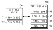
1 is a block diagram of a driving assistance system including a radar module according to an embodiment of the present invention.
The vehicle 1 according to the present invention includes a
Such a
In addition, the
Specifically, the
The acceleration sensor 196 measures the acceleration of the vehicle and may include a lateral acceleration sensor (not shown) and an acceleration sensor (not shown).
Assuming that the lateral acceleration sensor is the X-axis of the moving direction of the vehicle, the vertical acceleration (Y-axis) direction is referred to as the lateral direction, and the lateral acceleration is measured.
The longitudinal acceleration sensor can measure the acceleration in the direction of movement of the vehicle in the X-axis direction.
The acceleration sensor 196 detects a change in velocity per unit time and senses a dynamic force such as acceleration, vibration, shock, etc., and measures the inertia force, the electric strain, and the principle of the gyro. Thereafter, the measured acceleration value can be transmitted to the
The yaw rate sensor 197 can be installed on each wheel of the vehicle and can detect the yaw rate value in real time.
The yaw rate sensor (197) has a cesium crystal element inside the sensor. When the vehicle rotates while moving, the cesium crystal element itself generates a voltage while rotating. The yaw rate of the vehicle can be sensed based on the voltage thus generated.
Then, the measured yaw rate value can be transmitted to the
The
The
The
Specifically, the camera module 172 can be used for front and rear vehicles such as a lane departure warning device and a lane keeping assistant device, and an apparatus that operates according to an image of a road.
Also, the
However, as shown in FIG. 2, when detecting the position of the front vehicle through the
Further, when the distance from the front vehicle is increased, the section (b) where the radar measurement transverse position exhibits the tilting phenomenon may occur.
Therefore, as shown in FIG. 3, when the front vehicle is located near (a), a large offset error occurs so that the vehicle can continuously travel without being followed accurately by the center of the front vehicle.
The configuration of the
The configuration and operation of the
5 is a flow chart showing a control method of the
Referring to FIG. 4, the
First, the
The
The
Specifically, the signal processing unit 154 receives the electromagnetic wave transmitted from the
The signal processing unit 31 may receive sensor output values from various sensors included in the
For example, the yaw rate value acquired from the yaw rate sensor 197 and the vehicle speed acquired from the
The signal processing unit 31 transmits the time information of the electromagnetic wave transmitted from the
The main processor 32 determines whether the vehicle is traveling straight ahead or not based on the communication signals of various electronic devices through the
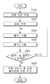
Specifically, FIG. 5 is a flowchart showing a control method of the
First, the main processor 32 calculates the current running radius of curvature based on the vehicle speed acquired from the
That is, when the radius of curvature exceeds a predetermined value on the basis of the calculated radius of curvature, it is determined that the vehicle is running straight. The
Further, based on the signal obtained from the
Thereafter, the main processor 32 calculates outputs 1 and 2 (S300 and S400) to determine whether an error in the lateral offset of the
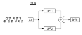
Specifically, Output 1 and Output 2 can be calculated with reference to FIGS. 6 and 7. FIG.
As shown in Fig. 6, the output 1 is input to the radar lateral position value X1 of the front vehicle sensed by the
That is, the difference between the two values obtained by passing through the LPF 1 having a large gain and the LPF 2 having a small gain can be regarded as an output 1.
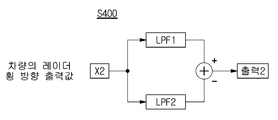
7, the output 2 receives the radar transverse output value X2 transmitted by the
That is, the difference between the two values obtained by passing through the LPF 1 having a large gain and the LPF 2 having a small gain can be regarded as an output 2.
At this time, if the obtained output 1 and output 2 are maintained for a predetermined time in a state where the obtained output 1 and output 2 are smaller than a preset threshold value (YES in S500), the lateral position value of the front vehicle sensed by the radar It can be judged that the offset error is likely to occur because the variation is small.
Accordingly, the
The additional vibration value is to compensate for the lateral offset error, and the lateral vibration width must not exceed half of the vehicle width to minimize the driver's discomfort. In addition, the vibration period should also be set appropriately to minimize discomfort to the driver (for example, 5 seconds or more).
Next, the memory 33 stores the program and data of the
Specifically, the memory (not shown) may be a volatile memory such as an S-RAM or a D-RAM, as well as a flash memory, a read only memory, an erasable programmable read only memory ), And electrically erasable programmable read only memory (EEPROM).
The nonvolatile memory may semi-permanently store a control program and control data for controlling the operation of the
While the present invention has been particularly shown and described with reference to exemplary embodiments thereof, it is clearly understood that the same is by way of illustration and example only and is not to be construed as limited to the embodiments set forth herein; It will be understood that various modifications may be made without departing from the spirit and scope of the invention.
1: vehicle 100: electronic device
Claims (8)
A communication unit receiving the vehicle speed and the yaw rate value; And
And a controller for decreasing a lateral offset error of the radar signal when it is determined that the vehicle is running straight ahead on the basis of the vehicle speed and the yaw rate value and the front vehicle is located below a predetermined distance based on the radar signal The radar module.
Wherein the lateral offset error of the radar signal is calculated based on the lateral position value of the front vehicle and the radar transverse output value transmitted from the radar sensor unit.
Wherein the control unit calculates a difference value obtained by passing the lateral position value of the front vehicle through two low pass filters having different gains and a radar lateral output value transmitted from the radar sensor unit using two low pass filters And determines that the offset error has occurred if the difference value obtained by passing the offset error is smaller than a preset threshold value.
Wherein the controller adds lateral vibration to the transmitted radar signal when it is determined that the offset error has occurred.
Receiving a vehicle speed and yaw rate value;
Determining whether the vehicle is traveling straight ahead based on the vehicle speed and the yaw rate;
Determining whether a preceding vehicle is located at a predetermined distance or less based on the radar signal; And
And decreasing a lateral offset error of the radar signal when the vehicle is in a straight traveling state and the front vehicle is judged to be located at a predetermined distance or less.
Wherein the lateral offset error of the radar signal is calculated on the basis of the lateral position value of the front vehicle and the lateral output value of the transmitted radar signal.
A difference value obtained by passing the transverse position value of the front vehicle through two low-pass filters having different gains and a radar transverse output value transmitted from the radar sensor unit are passed through two low-pass filters having different gains And determines that the offset error has occurred if the obtained difference value is smaller than a preset threshold value.
And adding a lateral vibration to the transmitted radar signal when it is determined that the offset error has occurred.
Priority Applications (1)
| Application Number | Priority Date | Filing Date | Title |
|---|---|---|---|
| KR1020150140327A KR20170040971A (en) | 2015-10-06 | 2015-10-06 | Radar module and method for controlling thereof |
Applications Claiming Priority (1)
| Application Number | Priority Date | Filing Date | Title |
|---|---|---|---|
| KR1020150140327A KR20170040971A (en) | 2015-10-06 | 2015-10-06 | Radar module and method for controlling thereof |
Publications (1)
| Publication Number | Publication Date |
|---|---|
| KR20170040971A true KR20170040971A (en) | 2017-04-14 |
Family
ID=58579567
Family Applications (1)
| Application Number | Title | Priority Date | Filing Date |
|---|---|---|---|
| KR1020150140327A KR20170040971A (en) | 2015-10-06 | 2015-10-06 | Radar module and method for controlling thereof |
Country Status (1)
| Country | Link |
|---|---|
| KR (1) | KR20170040971A (en) |
Cited By (13)
| Publication number | Priority date | Publication date | Assignee | Title |
|---|---|---|---|---|
| KR20180138477A (en) * | 2017-06-21 | 2018-12-31 | 현대오트론 주식회사 | Apparatus and method for detecting object in vehicle |
| WO2019009671A2 (en) | 2017-07-06 | 2019-01-10 | 주식회사 엘지화학 | Method for manufacturing composite material |
| WO2019009670A1 (en) | 2017-07-06 | 2019-01-10 | 주식회사 엘지화학 | Composite material |
| WO2019054815A1 (en) | 2017-09-15 | 2019-03-21 | 주식회사 엘지화학 | Method for producing composite material |
| WO2019054818A1 (en) | 2017-09-15 | 2019-03-21 | 주식회사 엘지화학 | Composite |
| WO2019054799A1 (en) | 2017-09-15 | 2019-03-21 | 주식회사 엘지화학 | Composite material |
| WO2019059730A1 (en) | 2017-09-22 | 2019-03-28 | 주식회사 엘지화학 | Composite material |
| WO2020032535A1 (en) | 2018-08-06 | 2020-02-13 | 주식회사 엘지화학 | Asymmetric composite material |
| WO2020067839A1 (en) | 2018-09-28 | 2020-04-02 | 주식회사 엘지화학 | Composite material |
| WO2020067838A1 (en) | 2018-09-28 | 2020-04-02 | 주식회사 엘지화학 | Wireless charging device |
| WO2020067837A1 (en) | 2018-09-28 | 2020-04-02 | 주식회사 엘지화학 | Composite material |
| WO2020067743A1 (en) | 2018-09-28 | 2020-04-02 | 주식회사 엘지화학 | Composite material |
| KR20230020083A (en) * | 2021-08-03 | 2023-02-10 | 공주대학교 산학협력단 | Road marking paint removal equipment and how to remove road marking paint using them |
-
2015
- 2015-10-06 KR KR1020150140327A patent/KR20170040971A/en not_active Application Discontinuation
Cited By (13)
| Publication number | Priority date | Publication date | Assignee | Title |
|---|---|---|---|---|
| KR20180138477A (en) * | 2017-06-21 | 2018-12-31 | 현대오트론 주식회사 | Apparatus and method for detecting object in vehicle |
| WO2019009671A2 (en) | 2017-07-06 | 2019-01-10 | 주식회사 엘지화학 | Method for manufacturing composite material |
| WO2019009670A1 (en) | 2017-07-06 | 2019-01-10 | 주식회사 엘지화학 | Composite material |
| WO2019054815A1 (en) | 2017-09-15 | 2019-03-21 | 주식회사 엘지화학 | Method for producing composite material |
| WO2019054818A1 (en) | 2017-09-15 | 2019-03-21 | 주식회사 엘지화학 | Composite |
| WO2019054799A1 (en) | 2017-09-15 | 2019-03-21 | 주식회사 엘지화학 | Composite material |
| WO2019059730A1 (en) | 2017-09-22 | 2019-03-28 | 주식회사 엘지화학 | Composite material |
| WO2020032535A1 (en) | 2018-08-06 | 2020-02-13 | 주식회사 엘지화학 | Asymmetric composite material |
| WO2020067839A1 (en) | 2018-09-28 | 2020-04-02 | 주식회사 엘지화학 | Composite material |
| WO2020067838A1 (en) | 2018-09-28 | 2020-04-02 | 주식회사 엘지화학 | Wireless charging device |
| WO2020067837A1 (en) | 2018-09-28 | 2020-04-02 | 주식회사 엘지화학 | Composite material |
| WO2020067743A1 (en) | 2018-09-28 | 2020-04-02 | 주식회사 엘지화학 | Composite material |
| KR20230020083A (en) * | 2021-08-03 | 2023-02-10 | 공주대학교 산학협력단 | Road marking paint removal equipment and how to remove road marking paint using them |
Similar Documents
| Publication | Publication Date | Title |
|---|---|---|
| KR20170040971A (en) | Radar module and method for controlling thereof | |
| EP3052961B1 (en) | Adaptive cruise control with on-ramp detection | |
| KR102005253B1 (en) | Lane assistance system responsive to extremely fast approaching vehicles | |
| JP6600001B2 (en) | How to control the distance between vehicles | |
| CN105121246B (en) | Method and apparatus for auxiliary of overtaking other vehicles | |
| US9508261B2 (en) | Method and device for operating a vehicle | |
| EP2698776B1 (en) | Vehicle control device and vehicle control method | |
| KR101987636B1 (en) | Control method for collision avoidance of vehicle and Apparatus for collision avoidance of vehicle implementing the same | |
| US20150239472A1 (en) | Vehicle-installed obstacle detection apparatus having function for judging motion condition of detected object | |
| US20140297170A1 (en) | Driving support system | |
| KR101946043B1 (en) | Vehicle-mounted apparatus for selecting preceding vehicle positioned in the travel path of the host vehicle of the apparatus | |
| KR20160115448A (en) | Driving assistant system in a vehicle and method thereof | |
| US9352774B2 (en) | Vehicle driving assistance apparatus | |
| KR101592971B1 (en) | On-board apparatus | |
| EP2405416B1 (en) | Adaptive cruise control method and system for controlling speed of vehicle | |
| JP2020021179A (en) | Driving support device | |
| KR101286466B1 (en) | Adaptive cruise control apparatus and control method for the same | |
| KR20190105155A (en) | Apparatus and method for setting velocity of vehicle | |
| JP4919849B2 (en) | Automotive radar equipment | |
| KR20210114689A (en) | Vehicle and method of controlling the same | |
| KR102221837B1 (en) | Apparatus for changing lane | |
| GB2564854A (en) | Vehicle controller and method | |
| JP4919850B2 (en) | Automotive radar equipment | |
| KR101976822B1 (en) | Smart cruise control system using radar & speed sensor and the control method | |
| KR102526079B1 (en) | Vehicle and control method for the same |
Legal Events
| Date | Code | Title | Description |
|---|---|---|---|
| A201 | Request for examination | ||
| E902 | Notification of reason for refusal |