KR20170040563A - Optical Film - Google Patents
Optical Film Download PDFInfo
- Publication number
- KR20170040563A KR20170040563A KR1020150139698A KR20150139698A KR20170040563A KR 20170040563 A KR20170040563 A KR 20170040563A KR 1020150139698 A KR1020150139698 A KR 1020150139698A KR 20150139698 A KR20150139698 A KR 20150139698A KR 20170040563 A KR20170040563 A KR 20170040563A
- Authority
- KR
- South Korea
- Prior art keywords
- liquid crystal
- degrees
- film
- angle
- optical film
- Prior art date
- Legal status (The legal status is an assumption and is not a legal conclusion. Google has not performed a legal analysis and makes no representation as to the accuracy of the status listed.)
- Granted
Links
- 239000012788 optical film Substances 0.000 title claims abstract description 116
- 239000010408 film Substances 0.000 claims abstract description 261
- 230000001747 exhibiting effect Effects 0.000 claims abstract description 4
- 239000004973 liquid crystal related substance Substances 0.000 claims description 267
- 239000007921 spray Substances 0.000 claims description 52
- 238000002834 transmittance Methods 0.000 claims description 51
- 238000010521 absorption reaction Methods 0.000 claims description 37
- 150000001875 compounds Chemical class 0.000 claims description 35
- 230000003287 optical effect Effects 0.000 claims description 30
- 239000004988 Nematic liquid crystal Substances 0.000 claims description 14
- 239000004984 smart glass Substances 0.000 claims description 7
- 230000005540 biological transmission Effects 0.000 abstract description 18
- 230000000903 blocking effect Effects 0.000 abstract description 6
- 239000010410 layer Substances 0.000 description 69
- 239000000758 substrate Substances 0.000 description 13
- 239000004820 Pressure-sensitive adhesive Substances 0.000 description 11
- 239000000853 adhesive Substances 0.000 description 9
- 230000001070 adhesive effect Effects 0.000 description 9
- 239000000203 mixture Substances 0.000 description 6
- 230000035699 permeability Effects 0.000 description 6
- 229920002284 Cellulose triacetate Polymers 0.000 description 5
- NNLVGZFZQQXQNW-ADJNRHBOSA-N [(2r,3r,4s,5r,6s)-4,5-diacetyloxy-3-[(2s,3r,4s,5r,6r)-3,4,5-triacetyloxy-6-(acetyloxymethyl)oxan-2-yl]oxy-6-[(2r,3r,4s,5r,6s)-4,5,6-triacetyloxy-2-(acetyloxymethyl)oxan-3-yl]oxyoxan-2-yl]methyl acetate Chemical compound O([C@@H]1O[C@@H]([C@H]([C@H](OC(C)=O)[C@H]1OC(C)=O)O[C@H]1[C@@H]([C@@H](OC(C)=O)[C@H](OC(C)=O)[C@@H](COC(C)=O)O1)OC(C)=O)COC(=O)C)[C@@H]1[C@@H](COC(C)=O)O[C@@H](OC(C)=O)[C@H](OC(C)=O)[C@H]1OC(C)=O NNLVGZFZQQXQNW-ADJNRHBOSA-N 0.000 description 5
- 230000000052 comparative effect Effects 0.000 description 5
- 229920000089 Cyclic olefin copolymer Polymers 0.000 description 4
- 239000011247 coating layer Substances 0.000 description 4
- 230000000694 effects Effects 0.000 description 4
- 238000000034 method Methods 0.000 description 4
- 229920000106 Liquid crystal polymer Polymers 0.000 description 3
- 239000004977 Liquid-crystal polymers (LCPs) Substances 0.000 description 3
- 229920000491 Polyphenylsulfone Polymers 0.000 description 3
- 239000004372 Polyvinyl alcohol Substances 0.000 description 3
- 230000007423 decrease Effects 0.000 description 3
- 238000011156 evaluation Methods 0.000 description 3
- 239000011521 glass Substances 0.000 description 3
- -1 polyethylene Polymers 0.000 description 3
- 229920002451 polyvinyl alcohol Polymers 0.000 description 3
- VYPSYNLAJGMNEJ-UHFFFAOYSA-N silicon dioxide Inorganic materials O=[Si]=O VYPSYNLAJGMNEJ-UHFFFAOYSA-N 0.000 description 3
- NIXOWILDQLNWCW-UHFFFAOYSA-M Acrylate Chemical compound [O-]C(=O)C=C NIXOWILDQLNWCW-UHFFFAOYSA-M 0.000 description 2
- 239000004697 Polyetherimide Substances 0.000 description 2
- 239000004698 Polyethylene Substances 0.000 description 2
- 230000003098 cholesteric effect Effects 0.000 description 2
- 239000011248 coating agent Substances 0.000 description 2
- 238000000576 coating method Methods 0.000 description 2
- 229920005994 diacetyl cellulose Polymers 0.000 description 2
- 238000010586 diagram Methods 0.000 description 2
- AMGQUBHHOARCQH-UHFFFAOYSA-N indium;oxotin Chemical compound [In].[Sn]=O AMGQUBHHOARCQH-UHFFFAOYSA-N 0.000 description 2
- 230000001678 irradiating effect Effects 0.000 description 2
- 239000007788 liquid Substances 0.000 description 2
- 239000000463 material Substances 0.000 description 2
- 230000010355 oscillation Effects 0.000 description 2
- 229920000058 polyacrylate Polymers 0.000 description 2
- 229920001230 polyarylate Polymers 0.000 description 2
- 239000004417 polycarbonate Substances 0.000 description 2
- 229920001601 polyetherimide Polymers 0.000 description 2
- 229920000573 polyethylene Polymers 0.000 description 2
- 235000012239 silicon dioxide Nutrition 0.000 description 2
- LIVNPJMFVYWSIS-UHFFFAOYSA-N silicon monoxide Chemical compound [Si-]#[O+] LIVNPJMFVYWSIS-UHFFFAOYSA-N 0.000 description 2
- 239000007787 solid Substances 0.000 description 2
- AUXIEQKHXAYAHG-UHFFFAOYSA-N 1-phenylcyclohexane-1-carbonitrile Chemical compound C=1C=CC=CC=1C1(C#N)CCCCC1 AUXIEQKHXAYAHG-UHFFFAOYSA-N 0.000 description 1
- WLPATYNQCGVFFH-UHFFFAOYSA-N 2-phenylbenzonitrile Chemical group N#CC1=CC=CC=C1C1=CC=CC=C1 WLPATYNQCGVFFH-UHFFFAOYSA-N 0.000 description 1
- ZCYVEMRRCGMTRW-UHFFFAOYSA-N 7553-56-2 Chemical compound [I] ZCYVEMRRCGMTRW-UHFFFAOYSA-N 0.000 description 1
- RYGMFSIKBFXOCR-UHFFFAOYSA-N Copper Chemical compound [Cu] RYGMFSIKBFXOCR-UHFFFAOYSA-N 0.000 description 1
- 239000004976 Lyotropic liquid crystal Substances 0.000 description 1
- 229920012266 Poly(ether sulfone) PES Polymers 0.000 description 1
- 239000004642 Polyimide Substances 0.000 description 1
- 239000004743 Polypropylene Substances 0.000 description 1
- BQCADISMDOOEFD-UHFFFAOYSA-N Silver Chemical compound [Ag] BQCADISMDOOEFD-UHFFFAOYSA-N 0.000 description 1
- YXFVVABEGXRONW-UHFFFAOYSA-N Toluene Chemical compound CC1=CC=CC=C1 YXFVVABEGXRONW-UHFFFAOYSA-N 0.000 description 1
- 235000010724 Wisteria floribunda Nutrition 0.000 description 1
- 229910021417 amorphous silicon Inorganic materials 0.000 description 1
- 229910052802 copper Inorganic materials 0.000 description 1
- 239000010949 copper Substances 0.000 description 1
- 229910021419 crystalline silicon Inorganic materials 0.000 description 1
- 150000001925 cycloalkenes Chemical class 0.000 description 1
- 238000001035 drying Methods 0.000 description 1
- 230000009977 dual effect Effects 0.000 description 1
- 239000000975 dye Substances 0.000 description 1
- 125000000524 functional group Chemical group 0.000 description 1
- PCHJSUWPFVWCPO-UHFFFAOYSA-N gold Chemical compound [Au] PCHJSUWPFVWCPO-UHFFFAOYSA-N 0.000 description 1
- 229910052737 gold Inorganic materials 0.000 description 1
- 239000010931 gold Substances 0.000 description 1
- 230000001771 impaired effect Effects 0.000 description 1
- 239000003999 initiator Substances 0.000 description 1
- 229910052740 iodine Inorganic materials 0.000 description 1
- 239000011630 iodine Substances 0.000 description 1
- 239000002346 layers by function Substances 0.000 description 1
- 238000004519 manufacturing process Methods 0.000 description 1
- 150000002848 norbornenes Chemical class 0.000 description 1
- 239000012994 photoredox catalyst Substances 0.000 description 1
- 239000004033 plastic Substances 0.000 description 1
- 229920003023 plastic Polymers 0.000 description 1
- 239000002985 plastic film Substances 0.000 description 1
- 229920006255 plastic film Polymers 0.000 description 1
- 230000010287 polarization Effects 0.000 description 1
- 229920003229 poly(methyl methacrylate) Polymers 0.000 description 1
- 229920000515 polycarbonate Polymers 0.000 description 1
- 229920001721 polyimide Polymers 0.000 description 1
- 229920000642 polymer Polymers 0.000 description 1
- 239000004926 polymethyl methacrylate Substances 0.000 description 1
- 229920001155 polypropylene Polymers 0.000 description 1
- 239000010453 quartz Substances 0.000 description 1
- 239000011347 resin Substances 0.000 description 1
- 229920005989 resin Polymers 0.000 description 1
- 150000003377 silicon compounds Chemical class 0.000 description 1
- 239000000377 silicon dioxide Substances 0.000 description 1
- 229910052709 silver Inorganic materials 0.000 description 1
- 239000004332 silver Substances 0.000 description 1
- 238000004088 simulation Methods 0.000 description 1
- 239000010409 thin film Substances 0.000 description 1
- 239000013598 vector Substances 0.000 description 1
Images


Classifications
-
- G—PHYSICS
- G02—OPTICS
- G02B—OPTICAL ELEMENTS, SYSTEMS OR APPARATUS
- G02B5/00—Optical elements other than lenses
- G02B5/30—Polarising elements
- G02B5/3025—Polarisers, i.e. arrangements capable of producing a definite output polarisation state from an unpolarised input state
- G02B5/3033—Polarisers, i.e. arrangements capable of producing a definite output polarisation state from an unpolarised input state in the form of a thin sheet or foil, e.g. Polaroid
- G02B5/3041—Polarisers, i.e. arrangements capable of producing a definite output polarisation state from an unpolarised input state in the form of a thin sheet or foil, e.g. Polaroid comprising multiple thin layers, e.g. multilayer stacks
-
- G—PHYSICS
- G02—OPTICS
- G02B—OPTICAL ELEMENTS, SYSTEMS OR APPARATUS
- G02B5/00—Optical elements other than lenses
- G02B5/30—Polarising elements
- G02B5/3083—Birefringent or phase retarding elements
-
- G—PHYSICS
- G02—OPTICS
- G02C—SPECTACLES; SUNGLASSES OR GOGGLES INSOFAR AS THEY HAVE THE SAME FEATURES AS SPECTACLES; CONTACT LENSES
- G02C7/00—Optical parts
- G02C7/10—Filters, e.g. for facilitating adaptation of the eyes to the dark; Sunglasses
-
- G—PHYSICS
- G02—OPTICS
- G02F—OPTICAL DEVICES OR ARRANGEMENTS FOR THE CONTROL OF LIGHT BY MODIFICATION OF THE OPTICAL PROPERTIES OF THE MEDIA OF THE ELEMENTS INVOLVED THEREIN; NON-LINEAR OPTICS; FREQUENCY-CHANGING OF LIGHT; OPTICAL LOGIC ELEMENTS; OPTICAL ANALOGUE/DIGITAL CONVERTERS
- G02F1/00—Devices or arrangements for the control of the intensity, colour, phase, polarisation or direction of light arriving from an independent light source, e.g. switching, gating or modulating; Non-linear optics
- G02F1/01—Devices or arrangements for the control of the intensity, colour, phase, polarisation or direction of light arriving from an independent light source, e.g. switching, gating or modulating; Non-linear optics for the control of the intensity, phase, polarisation or colour
- G02F1/13—Devices or arrangements for the control of the intensity, colour, phase, polarisation or direction of light arriving from an independent light source, e.g. switching, gating or modulating; Non-linear optics for the control of the intensity, phase, polarisation or colour based on liquid crystals, e.g. single liquid crystal display cells
- G02F1/133—Constructional arrangements; Operation of liquid crystal cells; Circuit arrangements
- G02F1/1333—Constructional arrangements; Manufacturing methods
- G02F1/1335—Structural association of cells with optical devices, e.g. polarisers or reflectors
- G02F1/133528—Polarisers
Landscapes
- Physics & Mathematics (AREA)
- General Physics & Mathematics (AREA)
- Optics & Photonics (AREA)
- Health & Medical Sciences (AREA)
- Ophthalmology & Optometry (AREA)
- Nonlinear Science (AREA)
- General Health & Medical Sciences (AREA)
- Mathematical Physics (AREA)
- Chemical & Material Sciences (AREA)
- Crystallography & Structural Chemistry (AREA)
- Liquid Crystal (AREA)
- Polarising Elements (AREA)
Abstract
본 출원은, 광학 필름 및 광학 필름의 용도에 관한 것으로, 시야각에 따른 선택적인 투과 및 차단 특성을 나타내는 광학 필름을 제공할 수 있고, 이러한 광학 필름은 LCD와 같은 표시 장치의 보안 필름, 스마트 윈도우 및 선 글라스 등에 유용하게 사용될 수 있다. The present application relates to the use of an optical film and an optical film, and can provide an optical film exhibiting selective transmission and blocking characteristics depending on a viewing angle. Such an optical film can be used as a security film for a display device such as an LCD, Sunglasses and the like.
Description
본 출원은, 광학 필름 및 광학 필름의 용도에 관한 것이다. This application relates to the use of optical films and optical films.
정보 보호 또는 개인 프라이버시의 중요성에 따라 보안 필름의 사용량이 증가하고 있다. 예를 들어 특허 문헌 1은 마이크로 루버(Micro Louver) 기술을 적용한 보안 필름을 개시하고 있다. 마이크로 루버 필름은 다수의 미세 루버가 일정한 간격으로 패턴화되어 있는 구조를 가진다. 루버 필름 내부에 형성된 다수의 미세 루버는 루버 필름을 투과하는 빛의 진행 방향을 소정의 유출 각도 범위로 제어하는 효과(방향 제어 효과)를 발휘한다. 따라서, 측면 방향으로의 액정 패널 투과광의 불필요한 유출을 방지할 수 있으며, 이와 같은 루버 필름을 광 제어 필름(Light Control Film)이라고도 부른다. 그러나, 마이크로 루버 필름은 종횡비가 보안 필름 성능의 주요 인자인데 선폭이 커질수록 높이는 작아질 수 있으나 선폭이 커지면 그만큼 투과도가 저하하는 문제점이 있다. The use of security films is increasing with the importance of information protection or personal privacy. For example,
본 출원은, 광학 필름 및 광학 필름의 용도를 제공한다.The present application provides uses of optical films and optical films.
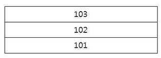
본 출원은 광학 필름에 관한 것이다. 예시적인 광학 필름은 제 1 선편광자, 제 1 액정 필름 및 제 2 액정 필름을 포함한다. 제 1 액정 필름 및 제 2 액정 필름은 제 1 선편광자의 상부에 순차로 형성되어 있을 수 있다. 또한, 제 1 액정 필름 및 제 2 액정 필름은 각각 스프레이 배향된 액정 화합물을 포함할 수 있다. 하나의 예시에서, 제 1 액정 필름 및 제 2 액정 필름 내의 액정 화합물은 각각 선형 스프레이 배향된 상태로 존재할 수 있다. 도 1은 제 1 선편광자(101), 제 1 액정 필름(102) 및 제 2 액정 필름(103)이 순차로 형성된 구조의 광학 필름을 예시적으로 나타낸다. The present application relates to optical films. An exemplary optical film includes a first linear polarizer, a first liquid crystal film, and a second liquid crystal film. The first liquid crystal film and the second liquid crystal film may be sequentially formed on the first linear polarizer. Further, the first liquid crystal film and the second liquid crystal film may each comprise a spray-aligned liquid crystal compound. In one example, the liquid crystal compounds in the first liquid crystal film and the second liquid crystal film may each be present in a linear spray orientation. Fig. 1 exemplarily shows an optical film having a structure in which a first
본 명세서에서 「편광자」는 입사 광에 대하여 선택적 투과 및 차단 특성, 예를 들어 반사 또는 흡수 특성을 나타내는 기능성 층을 의미한다. 편광자는 예를 들어, 여러 방향으로 진동하는 입사 광으로부터 어느 한쪽 방향으로 진동하는 광은 투과하고, 나머지 방향으로 진동하는 광은 차단시키는 기능을 가질 수 있다. 본 명세서에서 「선편광자」는 선택적으로 투과하는 광이 어느 하나의 방향으로 진동하는 선편광이고 선택적으로 차단하는 광이 상기 선편광의 진동 방향과 수직하는 방향으로 진동하는 선편광인 경우를 의미한다. 선 편광자의 종류는 특별히 제한되지 않고, 예를 들어 반사형 편광자으로서 예를 들어, DBEF(Dual Brightness Enhancement Film), 유방성 액정층(LLC층: Lyotropic Liquid Crystal) 또는 와이어 그리드 편광기(wire grid polarizer) 등을 사용할 수 있고, 흡수형 편광자으로서 예를 들어, PVA 연신 필름 등과 같은 고분자 연신 필름에 요오드를 염착한 편광자 또는 배향된 상태로 중합된 액정을 호스트로 하고, 상기 액정의 배향에 따라 배열된 이방성 염료를 게스트로 하는 게스트-호스트형 편광자를 사용할 수 있으나 이에 제한되는 것은 아니다. As used herein, the term " polarizer " means a functional layer that exhibits selective transmission and blocking characteristics, e.g., reflection or absorption characteristics, with respect to incident light. For example, the polarizer may have a function to transmit light that vibrates in one direction from incident light that vibrates in various directions, and to block light that vibrates in the other direction. In the present specification, the term " linear polarizer " means a linearly polarized light in which the light selectively transmitted is oscillated in one direction and the light selectively blocked is linearly polarized light oscillating in a direction perpendicular to the oscillation direction of the linearly polarized light. Examples of the polarizer include a dual brightness enhancement film (DBEF), a lyotropic liquid crystal (LLC layer), and a wire grid polarizer. Polarizers in which iodine is immobilized on a polymeric stretched film such as a PVA stretched film or a liquid crystal polymerized in an oriented state are used as the absorptive polarizers and anisotropic Guest-host polarizers with dyes as guest may be used, but are not limited thereto.
본 명세서에서 용어 「스프레이 배향」은 액정 필름 내에 존재하는 액정 화합물의 틸트각이 액정 필름의 두께 방향에 따라 점진적으로 변화하는 배향 상태를 의미한다. 본 명세서에서 용어 「틸트각」은 액정 화합물의 광축과 액정 필름의 표면이 이루는 최소각을 의미한다. 본 명세서에서 용어 「평균 틸트각」은 전체 액정 화합물의 틸트각의 평균치 또는 전체 액정 화합물의 배열을 평균치로 환산하였을 경우의 틸트각을 의미한다. 본 명세서에서 용어 「광축」은 액정 화합물이 막대 (rod) 모양인 경우 막대 모양의 장축 방향의 축을 의미하고, 액정 화합물이 원판 (discotic) 모양인 경우 원판 평면의 법선 방향의 축을 의미한다. 따라서, 본 명세서에서 「액정 필름이 스프레이 배향된 액정 화합물을 포함한다」는 것은 액정 화합물이 막대 모양인 경우 장축 방향이 액정 필름의 두께 방향에 따라 점진적으로 변화하는 것을 의미하고, 혹은 액정 화합물이 원판 모양인 경우 원판 평면의 법선 방향이 액정 필름의 두께 방향에 따라 점진적으로 변화하는 것을 의미한다. The term " spray orientation " as used herein means an alignment state in which the tilt angle of the liquid crystal compound present in the liquid crystal film changes gradually along the thickness direction of the liquid crystal film. In the present specification, the term " tilt angle " means the minimum angle formed by the optical axis of the liquid crystal compound and the surface of the liquid crystal film. In the present specification, the term " average tilt angle " means the tilt angle when the average value of the tilt angle of the whole liquid crystal compound or the total arrangement of liquid crystal compounds is converted into an average value. The term " optical axis " in this specification means a rod-shaped long axis in the case of a rod-shaped liquid crystal compound and an axis in the normal direction of the circular plate plane in the case where the liquid crystal compound is in a discotic form. Therefore, in the present specification, "the liquid crystal film includes a spray-aligned liquid crystal compound" means that the long axis direction gradually changes in accordance with the thickness direction of the liquid crystal film when the liquid crystal compound has a rod shape, Shape means that the normal direction of the plane of the disk gradually changes along the thickness direction of the liquid crystal film.
하나의 예시에서, 스프레이 배향은 예를 들어, 액정 필름 내의 액정 화합물의 최소 틸트각이 약 0도 내지 20도인 범위 내이고, 최대 틸트각이 약 70도 내지 90도인 범위 내에서, 상기 틸트각이 액정 필름의 두께 방향에 따라 점진적으로 변화하는 배향 상태를 의미할 수 있다. In one example, the spray orientation is, for example, within a range in which the minimum tilt angle of the liquid crystal compound in the liquid crystal film is within the range of about 0 to 20 degrees, and within a range of about 70 to 90 degrees of the maximum tilt angle, It may mean an alignment state that gradually changes in accordance with the thickness direction of the liquid crystal film.
스프레이 배향은 선형(Linear) 스프레이 배향과 비선형(non-Linear) 스프레이 배향으로 구분될 수 있다. 본 명세서에서 용어 「선형(Linear) 스프레이 배향」은 액정 필름의 두께를 x축으로 하고 해당 두께에 대응하는 로컬 틸트각(Local Tilt Angle)을 y축으로 하여 도시된 그래프가 선형 그래프를 나타내는 배향 상태, 즉 그 기울기가 상수(常數, constant)인 배향 상태를 의미한다. 하나의 예시에서, 선형 스프레이 배향은 액정 필름의 전체 두께(d)에 대한 해당 두께(z)의 비(z/d)를 x축으로 하고 (즉, x= 0 내지 1.0), 해당 두께에 대응하는 로컬 틸트각을 y축으로 하되, y축에서 최소 틸트각과 최대 틸트각의 간격(b)을 x= 0 내지 1.0 범위 내의 간격(a)과 동일하게 하여, 도시된 그래프의 기울기가 x축에 따라 일정한 배향 상태, 예를 들어, 평균 기울기가(tilt factor)가 약 0.95 내지 1.05 범위 내인 배향 상태를 의미할 수 있다 (도 24의 그래프 A 참조). The spray orientation can be divided into a linear spray orientation and a non-linear spray orientation. In the present specification, the term " linear spray orientation " refers to an orientation state in which the graph shown with the thickness of the liquid crystal film as x-axis and the local tilt angle corresponding to the thickness as y- , I.e., an orientation state in which the slope thereof is constant. In one example, the linear spray orientation is such that the ratio (z / d) of the thickness (z) to the total thickness (d) of the liquid crystal film is taken as the x axis (that is, x = 0 to 1.0) (B) of the minimum tilt angle and the maximum tilt angle in the y-axis is the same as the interval (a) in the range of x = 0 to 1.0, and the slope of the graph shown in FIG. May refer to an orientation state in which a constant orientation state, for example, an average tilt factor is in the range of about 0.95 to 1.05 (see graph A in FIG. 24).
이와 달리, 본 명세서에서 용어「비선형(non-linear) 스프레이 배향」은 액정 필름의 두께를 x축으로 하고 해당 두께에 대응하는 로컬 틸트각을 y축으로 하여 도시된 그래프가 비선형 그래프를 나타내는 배향 상태, 즉 그 기울기가 액정 필름의 두께에 따라 변화하는 배향 상태를 의미한다. 하나의 예시에서, 비선형 스프레이 배향은 액정 필름의 두께에 대한 틸트각의 기울기가 점진적으로 증가하거나 또는 점진적으로 감소하는 배향 상태를 의미할 수 있다. 하나의 예시에서, 비선형 스프레이 배향은 액정 필름의 전체 두께(d)에 대한 해당 두께(z)의 비(z/d)를 x축으로 하고 (즉, x= 0 내지 1.0), 해당 두께에 대응하는 로컬 틸트각을 y축으로 하되, y축에서 최소 틸트각과 최대 틸트각의 간격(b)을 x= 0 내지 1.0 범위 내의 간격(a)과 동일하게 하여, 도시된 그래프의 기울기가 x축에 따라 점진적으로 감소하되, 평균 기울기(tilt factor)가 약 0.95 미만이거나 (도 24의 그래프 B 참조) 또는 x축에 따라 점진적으로 증가하되, 평균 기울기(tilt factor)가 약 1.05 초과인 배향 상태를 의미할 수 있다 (도 24의 그래프 C 참조). Alternatively, the term " non-linear spray orientation " is used herein to mean an orientation state in which the graph shown by the thickness of the liquid crystal film on the x-axis and the local tilt angle corresponding to the thickness on the y- , I.e., an orientation state in which the slope thereof changes with the thickness of the liquid crystal film. In one example, the non-linear spray orientation may mean an orientation state in which the slope of the tilt angle relative to the thickness of the liquid crystal film gradually increases or gradually decreases. In one example, the non-linear spray orientation corresponds to the thickness (x = 0 to 1.0) with the ratio (z / d) of the corresponding thickness z to the total thickness d of the liquid crystal film as x axis (B) of the minimum tilt angle and the maximum tilt angle in the y-axis is the same as the interval (a) in the range of x = 0 to 1.0, and the slope of the graph shown in FIG. (See graph B in FIG. 24) or gradually increase along the x-axis, but with an average tilt factor of greater than about 1.05, meaning that the average tilt factor is less than about 0.95 (See graph C in Fig. 24).
본 명세서에서 틸트 팩터(tilt factor)에 대하여 특별한 언급이 없는 한, Axoscan((주)Axometrix사)을 이용하여 각도별 필름의 위상차를 측정하여 도출된 틸트 팩터 값을 의미할 수 있다. 스프레이 배향 액정 필름의 틸트 팩터는 스프레이 배향 액정 필름의 제조 시에 공정 온도를 조절함으로써 조절될 수 있다. 하나의 예시에서, 스프레이 배향 액정 필름은 공지의 스프레이 배향성 액정 조성물의 층을 경화시켜 제조될 수 있다. 상기에서 경화는 스프레이 배향성 액정 조성물의 층에 자외선을 조사함으로써 수행될 수 있고, 상기 자외선의 조사 시의 온도를 조절하는 것에 의하여 스프레이 배향 액정 필름의 틸트 팩터를 조절할 수 있다. 예를 들어, 자외선 조사 시의 온도가 높을수록 틸트 팩터가 상승하는 경향이 있다. As used herein, the tilt factor may be a derived tilt factor value obtained by measuring the phase difference of the film at different angles using Axoscan (Axometrix). The tilt factor of the spray alignment liquid crystal film can be controlled by adjusting the process temperature during the production of the spray alignment liquid crystal film. In one example, a spray-aligned liquid crystal film can be prepared by curing a layer of a known spray-oriented liquid crystal composition. The curing can be performed by irradiating ultraviolet rays to the layer of the spray orientation liquid crystal composition, and the tilt factor of the spray alignment liquid crystal film can be controlled by adjusting the temperature at the time of irradiation of the ultraviolet rays. For example, the higher the temperature at the time of ultraviolet irradiation, the more the tilt factor tends to rise.
제 1 및 제 2 액정 필름이 각각 선형 스프레이 배향된 액정 화합물을 포함하는 경우 광학 필름이 시야각에 다른 선택적인 투과율을 나타내는 데 유리하다. 선형 스프레이 배향 액정 필름을 형성하는 방법은 특별히 제한되지 않고, 예를 들어, 당 업계에 공지된 스프레이 배향성 액정 조성물의 층을 적절한 온도로 유지하면서 자외선을 조사하여 경화시킴으로써 형성할 수 있다. When the first and second liquid crystal films each include a linear spray-aligned liquid crystal compound, it is advantageous that the optical film exhibits a selective transmittance different from the viewing angle. The method of forming the linear spray-aligned liquid crystal film is not particularly limited and can be formed, for example, by irradiating ultraviolet rays and curing while keeping the layer of the spray-oriented liquid crystal composition known in the art at an appropriate temperature.
제 1 및/또는 제 2 액정 필름의 두께는, 스프레이 배향 액정의 굴절률 이방성, 액정 필름의 위상차 값, 균일한 코팅을 형성한다는 측면을 고려하여 적절히 조절될 수 있다. 예를 들어 제 1 및 제 2 액정 필름은 각각 약 0.1㎛ 내지 약 5㎛, 약 0.5㎛ 내지 약 5㎛, 약 1㎛ 내지 약 5㎛, 약 1.5㎛ 내지 약 4.5㎛, 약 2㎛ 내지 약 4㎛, 약 2.5㎛ 내지 3.5㎛ 또는 약 2.75㎛ 내지 3.25㎛ 범위의 두께로 형성할 수 있으나, 두께 범위가 반드시 상기 범위로 제한되는 것은 아니다. The thickness of the first and / or second liquid crystal films can be appropriately adjusted in consideration of the refractive index anisotropy of the spray alignment liquid crystal, the retardation value of the liquid crystal film, and the aspect of forming a uniform coating. For example, the first and second liquid crystal films may each have a thickness of from about 0.1 탆 to about 5 탆, from about 0.5 탆 to about 5 탆, from about 1 탆 to about 5 탆, from about 1.5 탆 to about 4.5 탆, 탆, about 2.5 탆 to 3.5 탆, or about 2.75 탆 to 3.25 탆, but the thickness range is not necessarily limited to the above range.
또한, 제 1 및/또는 제 2 액정 필름의 두께는, 경사각에서 선택적인 투과 특성을 나타내는데 있어서, Cut-off angle, 즉 투과도가 처음으로 최소가 되는 동경각의 각도와 Cut-off angle 및 그 이후 각도에서의 투과율과 연관성이 있다. 하나의 예시에서, 제 1 및/또는 제 2 액정 필름의 두께가 증가할수록 Cut-off angle이 작아지고, Cut-off angle에서의 투과율이 감소하는 경향이 있다. 따라서, 광학 필름의 차단 성능을 고려하면 액정 필름의 두께를 두껍게 설계하는 것이 유리할 수 있다. 다만, 제 1 및/또는 제 2 액정 필름의 두께가 증가할수록 Cut-off angle 이후의 각도에서 투과율이 상대적으로 빠르게 상승하는 경항이 있다. 상기 액정 필름의 두께에 따른 선택적인 투과 특성의 경향성을 고려하면 제 1 및 제 2 액정 필름의 두께 범위를 각각 상기 범위 내로 하는 것이 적절할 수 있다. 다만, 전술한 바와 같이 제 1 및/또는 제 2 액정 필름의 두께는 상기 범위에 제한되는 것은 아니고 선택적이 투과 특성에 있어서 요구되는 Cut-off angle과 Cut-off angle 및 그 후의 각도에서의 투과율을 적절히 고려하여 상기 범위 외의 두께로도 조절될 수 있다.In addition, the thickness of the first and / or second liquid crystal films may be selected so that the cut-off angle, that is, the angle of the longest angle of view for which the transmittance first becomes minimum and the cut-off angle, It is related to the transmittance at an angle. In one example, as the thickness of the first and / or second liquid crystal film increases, the cut-off angle tends to decrease and the transmittance tends to decrease at the cut-off angle. Therefore, considering the blocking performance of the optical film, it may be advantageous to design the thickness of the liquid crystal film to be large. However, as the thickness of the first and / or second liquid crystal film increases, the transmittance increases relatively rapidly at an angle after the cut-off angle. Considering the tendency of selective transmission characteristics depending on the thickness of the liquid crystal film, it may be appropriate to set the thickness ranges of the first and second liquid crystal films within the respective ranges. However, as described above, the thickness of the first and / or second liquid crystal films is not limited to the above range, and the cut-off angle and the cut-off angle required for the selective transmission characteristics and the transmittance at an angle thereafter And may be adjusted to a thickness other than the above-mentioned range with proper consideration.
하나의 예시에서, 제 1 및/또는 제 2 액정 필름 내에 포함되는 액정 화합물은 중합성 액정 화합물일 수 있다. 제 1 및/또는 제 2 액정 필름은 예를 들어, 중합성 액정 화합물을 중합된 형태로 포함할 수 있다. 본 명세서에서 용어 「중합성 액정 화합물」은, 액정성을 나타낼 수 있는 부위, 예를 들면, 메소겐(mesogen) 골격 등을 포함하고, 또한 중합성 관능기를 하나 이상 포함하는 화합물을 의미할 수 있다. 또한, 「중합성 액정 화합물이 중합된 형태로 포함되어 있다는 것」은 상기 액정 화합물이 중합되어 액정 필름 내에서 액정 고분자의 주쇄 또는 측쇄와 같은 골격을 형성하고 있는 상태를 의미할 수 있다. 중합성 액정 화합물로는 막대 형상의 중합성 액정 화합물 또는 원판 현상의 액정 화합물도 적절히 선택하여 사용할 수 있다. In one example, the liquid crystal compound contained in the first and / or second liquid crystal film may be a polymerizable liquid crystal compound. The first and / or second liquid crystal film may contain, for example, a polymerizable liquid crystal compound in a polymerized form. As used herein, the term " polymerizable liquid crystal compound " may mean a compound containing a moiety capable of exhibiting liquid crystallinity, for example, a mesogen skeleton, and further containing at least one polymerizable functional group . Further, "the polymerizable liquid crystal compound is contained in a polymerized form" may mean a state in which the liquid crystal compound is polymerized to form a skeleton such as a main chain or side chain of the liquid crystal polymer in the liquid crystal film. As the polymerizable liquid crystal compound, a rod-shaped polymerizable liquid crystal compound or a liquid crystal compound of a discotic phenomenon can be appropriately selected and used.
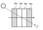
광학 필름은 예를 들어, 시야각에 따른 선택적인 투과율을 나타낼 수 있다. 하나의 예시에서, 광학 필름은 소정 동경각 및 경사각에서 관찰하는 경우 낮은 투과율을 나타낼 수 있고, 상기 소정 동경각 이외의 동경각의 경사각에서 관찰하는 경우 높은 투과율을 나타낼 수 있다. 본 명세서에서 용어 「경사각 및 동경각」은 도 2를 참조하여 설명할 수 있다. 예를 들어, 도 2에서 x축과 y축에 의한 평면 (xy 평면)을 광학 필름의 표면이라고 하면, 경사각은 상기 xy 평면의 법선, 즉 도 2의 z축과 관찰 방향(P)이 이루는 각도(도 2의 Θ)를 의미한다. 또한, 동겨각은 예를 들면, x축과 관찰 방향(P)의 xy 평면에 대한 투영이 이루는 각도(도 2의 Φ)를 의미한다. 본 명세서에서 특별한 언급이 없는 한 경사 광은 약 30도 내지 50도 범위 내의 경사각에서 입사되는 광을 의미할 수 있다.The optical film may exhibit a selective transmittance depending on, for example, a viewing angle. In one example, the optical film may exhibit a low transmittance when observed at a predetermined isometric angle and a tilt angle, and may exhibit a high transmittance when observed at an inclination angle other than the predetermined isometric angle. In this specification, the terms "tilt angle and longitude angle" can be described with reference to FIG. For example, in FIG. 2, when the plane (xy plane) by the x axis and the y axis is the surface of the optical film, the inclination angle is an angle formed by the normal of the xy plane, (&Amp;thetas; in Fig. 2). The coarse angle means, for example, the angle (陸 in Fig. 2) formed by the projection on the x-axis and the xy plane of the viewing direction (P). Unless otherwise specified herein, tilted light may refer to light incident at an oblique angle within a range of about 30 degrees to about 50 degrees.
광학 필름은 예를 들어, 제 1 및 제 2 액정 필름의 광축과 제 1 선 편광자의 흡수축을 조절하는 것에 의하여 시야각에 따른 선택적인 투과율을 설계할 수 있다. 이하, 본 명세서에서 용어 「수직, 직교, 수평 또는 평행」은, 목적하는 효과를 손상시키지 않은 범위에서의 실질적인 수직, 직교, 수평 또는 평행을 의미한다. 따라서, 상기 각 용어는, 예를 들면, ±15도 이내, ±10도 이내, ±5도 이내 또는 ±3도 이내의 오차를 포함할 수 있다.The optical film can design a selective transmittance according to the viewing angle, for example, by adjusting the optical axis of the first and second liquid crystal films and the absorption axis of the first linear polarizer. Herein, the term " vertical, orthogonal, horizontal, or parallel " means substantially vertical, orthogonal, horizontal, or parallel to the extent that the desired effect is not impaired. Therefore, each of the above terms may include an error within ± 15 °, within ± 10 °, within ± 5 °, or within ± 3 °, for example.
하나의 예시에서, 제 1 및/또는 제 2 액정 필름의 평균 광축의 제 1 및 제 2 액정 필름 평면으로의 투영은 제 1 선평자의 흡수축과 평행을 이룰 수 있다. 본 명세서에서 용어 「평균 광축」은 액정 필름 내의 존재하는 광축의 벡터들의 합을 의미할 수 있다. In one example, the projection of the average optical axis of the first and / or second liquid crystal film onto the first and second liquid crystal film planes may be parallel to the absorption axis of the first line. As used herein, the term " average optical axis " may mean the sum of the vectors of the optical axes present in the liquid crystal film.
하나의 구체적인 예시에서, 제 1 및 제 2 액정 필름의 평균 광축의 제 1 및 제 2 액정 필름 평면으로의 투영은 각각 제 1 선평자의 흡수축과 평행을 이룰 수 있다. 이러한 광학 필름은 예를 들어, 동경각 85 내지 95의 경사각에서 관찰하는 경우 및 동경각 265도 내지 275도의 경사각에서 관찰하는 경우에 대하여 상대적으로 낮은 투과율을 나타낼 수 있다. 이러한 광학 필름은 또한, 상기 동경각 이외의 동경각, 예를 들어 동경각 355도 내지 5도의 경사각에서 관찰하는 경우 및 동경각 175도 내지 185도의 경사각에서 관찰하는 경우에 대하여 상대적으로 높은 투과율을 나타낼 수 있다. In one specific example, the projections of the average optical axis of the first and second liquid crystal films to the first and second liquid crystal film planes may be parallel to the absorption axis of the first line chart, respectively. Such an optical film can exhibit a relatively low transmittance, for example, when observed at an oblique angle of 85 to 95 degrees and at an oblique angle of 265 to 275 degrees. Such an optical film may also exhibit a relatively high transmissivity relative to a case of observing at a long-angle angle other than the above-mentioned long-angle angle, for example, an oblique angle of 355 to 5 degrees and a oblique angle of 175 to 185 degrees .
하나의 예시에서, 상기 광학 필름은 동경각 85 내지 95도에서 경사각 50도로 입사하는 광 및 동경각 265도 내지 275에서 경사각 50도로 입사하는 광에 대하여 각각 약 30% 이하의 투과율을 나타낼 수 있다. 또한, 상기 광학 필름은 동경각 355도 내지 5도에서 경사각 50도로 입사하는 광 및 동경각 175도 내지 185도에서 경사각 50도로 입사하는 광에 대하여 각각 약 80% 이상의 투과율을 나타낼 있다. In one example, the optical film may exhibit transmittance of about 30% or less for light incident at an inclination angle of 50 degrees at a longitude angle of 85 to 95 degrees and light incident at an inclination angle of 50 degrees at an aperture angle of 265 to 275 degrees. In addition, the optical film exhibits a transmittance of about 80% or more for light incident at an inclination angle of 50 degrees at a longitude of 355 degrees to 5 degrees and for light incident at an angle of incidence of 50 degrees at an angle of 175 degrees to 185 degrees.
본 명세서에서 경사각에 대한 투과율에 대하여 기재하면서 특별한 언급이 없는 경우 약 50도 경사각에서의 투과율을 의미할 수 있다. 또한, 본 명세서에서 동경각에 대한 투과율을 기재하면서 특별한 언급이 없는 경우, 제 1 선편자의 흡수축을 동경각 약 0도 및 약 180도로 보는 경우의 동경각에 대한 투과율을 의미할 수 있다. In the present specification, the transmittance at an oblique angle is described while it may mean a transmittance at an oblique angle of about 50 degrees unless otherwise specified. In the present specification, the transmittance for the long axis can be referred to as the transmittance for the long axis when the absorption axis of the first line segment is viewed at about 0 degrees and about 180 degrees.
다른 하나의 예시에서, 제 1 및/또는 제 2 액정 필름의 평균 광축의 제 1 및/또는 제 2 액정 필름의 평면으로의 투영은 각각 제 1 선편광자의 흡수축과 약 10도 이상의 각도를 이루도록 배치될 수 있다. 상기 각도는, 보다 구체적으로 약 10도 이상, 약, 12.5도 이상, 약 15도 이상, 약 17.5도 이상, 약 20도 이상일 수 있으나, 이에 제한되는 것은 아니고 목적하는 시야각의 선택적인 투과 특성을 고려하여 적절히 선택될 수 있다. 이러한 광학 필름은 동경각 85 내지 95의 경사각에서 관찰하는 경우 및 동경각 265도 내지 275의 경사각에서 관찰하는 경우에 대하여 상대적으로 낮은 투과율을 나타낼 수 있고, 상기 동경각 이외의 동경각, 예를 들어 동경각 355도 내지 5도의 경사각에서 관찰하는 경우 및 동경각 175도 내지 185도의 경사각에서 관찰하는 경우에 대하여 상대적으로 높은 투과율을 나타낼 수 있다. In another example, the projection of the average optical axis of the first and / or second liquid crystal film onto the plane of the first and / or second liquid crystal film is arranged so as to form an angle of about 10 degrees or more with respect to the absorption axis of the first linear polarizer, . The angle may be more specifically about 10 degrees or more, about 12.5 degrees or more, about 15 degrees or more, about 17.5 degrees or more, about 20 degrees or more, but it is not limited thereto and the selective transmission characteristic of a desired viewing angle may be considered And can be appropriately selected. Such an optical film can exhibit a relatively low transmittance when observed at an oblique angle of 85 to 95 nm and at an oblique angle of 265 to 275, A relatively high transmittance can be exhibited when observed at an inclination angle of 355 degrees to 5 degrees and at an inclination angle of 175 degrees to 185 degrees.
하나의 예시에서, 상기 광학 필름은 동경각 85 내지 95도에서 경사각 50도로 입사되는 광에 대하여 약 10% 이하의 투과율을 나타낼 수 있고, 동경각 265도 내지 275에서 경사각 50로 입사되는 광에 대하여 약 60% 이하의 투과율을 나타낼 수 있다. 또한, 상기 광학 필름은 동경각 355도 내지 5도에서 경사각 50도로 입사되는 광 및 동경각 175도 내지 185도에서 경사각 50도로 입사되는 광에 대하여 각각 약 80% 이상의 투과율을 나타낼 있다.In one example, the optical film may exhibit transmittance of about 10% or less with respect to light incident at an inclination angle of 50 to 95 degrees with respect to a light incident at an inclination angle of 50 to 265 to 275, A transmittance of about 60% or less can be exhibited. In addition, the optical film exhibits a transmittance of about 80% or more for light incident at an inclination angle of 50 degrees at a longitude of 355 degrees to 5 degrees and for light incident at an angle of incidence of 50 degrees at 175 degrees to 185 degrees.
다른 하나의 예시에서, 제 1 및/또는 제 2 액정 필름의 평균 광축의 제 1 및 제 2 액정 필름 평면으로의 투영은 제 1 선평자의 흡수축과 평행을 이루도록 배치될 수 있다. 하나의 구체적인 예시에서, 제 1 및 제 2 액정 필름의 평균 광축의 제 1 및 제 2 액정 필름 평면으로의 투영은 제 1 선평자의 흡수축과 평행을 이루도록 배치될 수 있다. 이러한 광학 필름은 동경각 355도 내지 5의 경사각에서 관찰하는 경우 및 동경각 175도 내지 185도의 경사각에서 관찰하는 경우 상대적으로 낮은 투과율을 나타낼 수 있고. 상기 동걍각 이외의 동경각, 예를 들어 동경각 85 내지 95도의 경사각에서 관찰하는 경우 및 동경각 265도 내지 275도의 경사각에서 관찰하는 경우 상대적으로 높은 투과율을 나타낼 수 있다.In another example, the projection of the average optical axis of the first and / or second liquid crystal film onto the first and second liquid crystal film planes may be arranged to be parallel to the absorption axis of the first line chart. In one specific example, the projection of the average optical axis of the first and second liquid crystal films onto the first and second liquid crystal film planes may be arranged to be parallel to the absorption axis of the first line film. Such an optical film can exhibit a relatively low transmittance when observed at an inclination angle of 355 degrees to 5 degrees and at an inclination angle of 175 degrees to 185 degrees. A relatively high transmittance can be exhibited when observation is performed at a longitude angle other than the above-mentioned copper angle, for example, at an inclination angle of 85 to 95 degrees and at an inclination angle of 265 to 275 degrees.
하나의 예시에서, 상기 광학 필름은 동경각 355도 내지 5도에서 경사각 50로 입사되는 광 및 동경각 175도 내지 185도에서 경사각 50도로 입사하는 광에 대하여 각각 약 30% 이하의 투과율을 나타낼 수 있다. 또한, 상기 광학 필름은 동경각 85 내지 95도에서 경사각 50도로 입사하는 광 및 동경각 265도 내지 275도에서 경사각 50도로 입사하는 광에 대하여 각각 약 80% 이상의 투과율을 나타낼 수 있다. In one example, the optical film may have a transmittance of about 30% or less for light incident at an oblique angle of 50 at an angular range of 355 to 5 degrees and for light incident at an oblique angle of 50 degrees at an angle of 175 to 185 degrees have. In addition, the optical film may exhibit transmittance of about 80% or more for light incident at an inclination angle of 50 degrees at a longitude angle of 85 to 95 degrees and for light incident at an inclination angle of 50 degrees at an aperture angle of 265 to 275 degrees.
본 출원에서 제 1 및 제 2 액정 필름의 광축과 제 1 선 편광자의 흡수축의 설계는 상기에 제한되는 것은 아니고 목적하는 시야각에 따른 선택적인 투과율을 고려하여 적절히 변경될 수 있다. The design of the optical axis of the first and second liquid crystal films and the absorption axis of the first linear polarizer in the present application is not limited to the above but may be appropriately changed in consideration of the selective transmittance according to the desired viewing angle.
제 1 및/또는 제 2 액정 필름의 스프레이 배향의 회전 방향은 본 출원의 목적을 손상시키지 않는 범위 내에서 적절히 선택될 수 있다. 본 명세서에서 용어 「스프레이 배향의 회전 방향」은 틸트각이 증가하는 방향을 의미할 수 있다. 예를 들어, 틸트각이 증가하는 방향이 시계 방향인 경우 우회전 스프레이 배향으로 호칭할 수 있고, 틸트각이 증가하는 방향이 반 시계 방향인 경우 좌회전 스프레이 배향으로 호칭할 수 있다. 하나의 예시에서, 제 1 및 제 2 액정 필름의 스프레이 배향의 회전 방향은 서로 동일할 수 있다. 예를 들어, 제 1 및 제 2 액정 필름은 각각 우회전 스프레이 배향 상태를 가지거나 또는 각각 좌회전 스프레이 배향 상태를 가질 수 있다. 다른 하나의 예시에서, 제 1 및 제 2 액정 필름은 스프레이 배향의 회전 방향이 서로 상이할 수 있다. 예를 들어, 제 1 액정 필름은 우회전 스프레이 배향을 가지고, 제 2 액정 필름은 좌회전 스프레이 배향을 가지거나, 또는 제 1 액정 필름은 좌회전 스프레이 배향을 가지고, 제 2 액정 필름은 우회전 스프레이 배향을 가질 수 있다. The direction of rotation of the spray orientation of the first and / or second liquid crystal film can be appropriately selected within a range that does not impair the purpose of the present application. As used herein, the term " rotational direction of spray orientation " may refer to a direction in which the tilt angle increases. For example, when the direction in which the tilt angle increases is clockwise, it can be referred to as a right rotation spray orientation, and when the direction in which the tilt angle increases is counterclockwise, it can be referred to as a left rotation spray orientation. In one example, the rotational directions of the spray orientations of the first and second liquid crystal films may be the same as each other. For example, the first and second liquid crystal films may each have a right turn spray orientation state or a left turn spray orientation state, respectively. In another example, the first and second liquid crystal films may have different rotation directions of the spray orientation. For example, the first liquid crystal film may have a right turn spray orientation, the second liquid crystal film may have a left turn spray orientation, or the first liquid crystal film may have a left turn spray orientation and the second liquid crystal film may have a right turn spray orientation have.
제 1 및 제 2 액정 필름 간의 계면에서의 틸트각은 본 출원의 목적을 손상시키지 않는 범위 내에서 적절히 조절될 수 있다. 본 명세서에서 「제 1 및 제 2 액정 필름 간의 계면에서의 틸트각」은 제 1 액정 필름에서 제 2 액정 필름과 가장 인접하는 영역의 틸트각과 제 2 액정 필름에서 제 1 액정 필름과 가장 인접하는 영역의 틸트각이 이루는 각도를 의미할 수 있다. 하나의 예시에서, 제 1 및 제 2 액정 필름 간의 계면에서의 틸트각은 약 0도 내지 20도, 약 0도 내지 18도, 약 0도 내지 16도, 약 0도 내지 14도 약 0도 내지 12도 또는 약 0도 내지 10도를 이룰 수 있다. 다른 하나의 예시에서, 제 1 및 제 2 액정 필름 간의 계면에서의 틸트각은 약 70도 내지 90도, 약 72도 내지 90도, 약 74도 내지 90도, 약 76도 내지 90도, 약 78도 내지 90도 또는 약 80 도 내지 90도를 이룰 수 있다. The tilt angle at the interface between the first and second liquid crystal films can be appropriately adjusted within a range that does not impair the purpose of the present application. In the present specification, the "tilt angle at the interface between the first and second liquid crystal films" is the tilt angle of the region closest to the second liquid crystal film in the first liquid crystal film and the tilt angle of the region closest to the first liquid crystal film in the second liquid crystal film And the tilt angle of the tilt angle. In one example, the tilt angle at the interface between the first and second liquid crystal films is about 0 to 20 degrees, about 0 to 18 degrees, about 0 to 16 degrees, about 0 to 14 degrees, 12 degrees or about 0 degrees to 10 degrees. In another example, the tilt angle at the interface between the first and second liquid crystal films is about 70 to 90 degrees, about 72 to 90 degrees, about 74 to 90 degrees, about 76 to 90 degrees, about 78 To about 90 degrees or about 80 degrees to about 90 degrees.
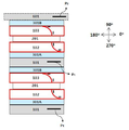
도 3 및 4는 제 1 및/또는 제 2 액정 필름의 스프레이 배향의 회전 방향 및 계면에서의 틸트각을 설명하기 위한 예시적인 도면이다. 하나의 예시에서, 광학 필름은 도 3에 나타낸 바와 같이, 제 1 액정 필름 (102) 및 제 2 액정 필름(103)이 각각 우회전 스프레이 배향을 가지며, 제 1 및 제 2 액정 필름 간의 계면에서의 틸트각이 약 0도를 이룰 수 있다 (─표시는 광축). 다른 하나의 예시에서, 광학 필름은 도 4에 나타낸 바와 같이, 제 1 액정 필름(102)은 좌회전 스프레이 배향을 가지고, 제 2 액정 필름(103)은 우회전 스프레이 배향을 가지며, 제 1 및 제 2 액정 필름 간의 계면에서의 틸트각이 약 80도 내지 90도를 이룰 수 있다(─표시는 광축)Figs. 3 and 4 are exemplary views for explaining the tilt angle in the rotation direction and the interface of the spray orientation of the first and / or second liquid crystal films. In one example, as shown in Fig. 3, the optical film has the first
제 1 및/또는 제 2 액정 필름의 위상차 값은 본 출원의 목적을 손상시키지 않는 범위 내에서 적절히 선택될 수 있다. 예를 들어, 제 1 및/또는 제 2 액정 필름은 하기 수식 A로 규정되는 면상 위상차 값(Rin)이 약 150 nm 내지 약 650 nm 범위 내일 수 있다. 제 1 및/또는 제 2 액정 필름이 상기 위상차 값을 가지는 경우, 광학 필름이 시야각에 대한 선택적인 투과율을 나타내는 것에 유리하지만, 위상차 값이 반드시 상기 범위로 제한되는 것은 아니다. The retardation value of the first and / or second liquid crystal film can be appropriately selected within a range not to impair the purpose of the present application. For example, the first and / or second liquid crystal films may have an in-plane retardation value (Rin) defined by the following formula A within the range of about 150 nm to about 650 nm. When the first and / or second liquid crystal film has the retardation value, it is advantageous that the optical film exhibits a selective transmittance with respect to the viewing angle, but the retardation value is not necessarily limited to the above range.
[수식 A] [Formula A]
Rin = d × (nx - ny)Rin = d x (nx - ny)
수식 A에서 d는 액정 필름의 두께이고, nx는 액정 필름의 평면에서 지상축 방향의 굴절률이며, ny는 액정 필름의 상기 지상축에 수직하는 방향의 굴절률이다. 본 명세성서 용어 「굴절률」은 특별히 달리 규정하지 않는 한, 550nm파장의 광에 대한 굴절률일 수 있다. In the formula A, d is the thickness of the liquid crystal film, nx is the refractive index in the slow axis direction in the plane of the liquid crystal film, and ny is the refractive index in the direction perpendicular to the slow axis of the liquid crystal film. The term "refractive index" in this specification can be a refractive index for light with a wavelength of 550 nm, unless otherwise specified.
광학 필름은 또한, 선형 스프레이 배향된 액정 화합물을 포함하는 제 3 액정 필름을 추가로 포함할 수 있다. 제 3 액정 필름에서 선형 스프레이 배향에 대한 구체적인 사항은 제 1 액정 필름 및 제 2 액정 필름의 항목에서 기술한 내용이 동일하게 적용될 수 있다. 하나의 예시에서, 제 3 액정 필름은 도 5에 나타낸 바와 같이, 제 1 액정 필름 (102) 및 제 2 액정 필름 (103)의 사이에 존재할 수 있다. 이 경우, 제 1 및 제 2 액정 필름은 스프레이 배향의 회전 방향이 서로 동일할 수 있고, 예를 들어, 서로 동일한 우회전 스프레이 배향을 가질 수 있다. 또한, 도 5에 나타낸 바와 같이, 상기 제 3 액정 필름과 제 1 액정 필름 간의 계면에서의 틸트각 및/또는 제 3 액정 필름과 제 1 액정 필름 간의 계면에서의 틸트각은 각각 약 70도 내지 90도, 약 72도 내지 90도, 약 74도 내지 90도, 약 76도 내지 90도, 약 78도 내지 90도 또는 약 80 도 내지 90도를 이룰 수 있다. 이러한 광학 필름은 넓은 파장 대역의 광, 예를 들어, 가시광의 전 파장 대역의 광에 대하여 상기 시야각에 따른 선택적인 투과 특성을 균일하게 나타낸다는 측면에서 유리하다. 즉, 상기 광학 필름은 넓은 파장 대역에서 균일한 투과 특성을 나타내므로 우수한 컬러 특성을 나타낼 수 있다. The optical film may further comprise a third liquid crystal film comprising a linear spray oriented liquid crystal compound. The details of the linear spray orientation in the third liquid crystal film may be the same as those described in the items of the first liquid crystal film and the second liquid crystal film. In one example, the third liquid crystal film may exist between the first
광학 필름은 하기 일반식 1을 만족하고 하기 수식 B로 규정되는 두께 방향 위상차 값(Rth)이 양수인 위상차 필름을 추가로 포함할 수 있다. 이러한 위상차 필름은 소위 +C Plate로 호칭될 수 있다. The optical film may further include a retardation film satisfying the following general formula (1) and having a thickness direction retardation value (Rth) defined by the following equation (B) being positive. Such a retardation film can be called a so-called + C plate.
[일반식 1] [Formula 1]
nx≒ny≠nz n x ≒ n y ≠ n z
[수식 B] [Formula B]
Rth = d × (nz - ny)Rth = d x (nz - ny)
일반식 1 또는 수식 B에서 d는 위상차 필름의 두께이고, nx는 위상차 필름의 평면에서 지상축 방향의 굴절률이며, ny는 위상차 필름의 상기 지상축에 수직하는 방향의 굴절률이고, nz는 위상차 필름의 두께 방향, 즉 상기 지상축과 그에 수직하는 방향 모두와 수직하는 방향의 굴절률이다In the formula (1) or (B), d is the thickness of the retardation film, nx is the refraction index in the slow axis direction in the plane of the retardation film, ny is the refraction index in the direction perpendicular to the slow axis of the retardation film, That is, the refractive index in the direction perpendicular to both the slow axis and the direction perpendicular thereto
하나의 예시에서, 상기 위상차 필름은 수직 배향 상태로 존재하는 액정 화합물을 포함할 수 있다. 본 명세서에서 「수직 배향」은 액정 화합물의 광축이 액정 필름 평면에 대하여 약 90도 내지 약 65도, 약 90도 내지 약 75도, 약 90도 내지 약 80도, 약 90도 내지 약 85도 약 90도의 경사각을 가지는 것을 의미할 수 있다. 하나의 예시에서, 위상차 필름은 도 7에 나타낸 바와 같이, 제 1 액정 필름 및 제 2 액정 필름의 사이에 존재할 수 있다. . 이 경우, 제 1 및 제 2 액정 필름은 스프레이 배향의 회전 방향이 서로 동일할 수 있고, 예를 들어, 서로 동일한 우회전 스프레이 배향을 가질 수 있다. 또한, 도 6에 나타낸 바와 같이, 위상차 필름과 제 1 액정 필름 간의 계면에서의 틸트각 및/또는 위상차 필름과 제 1 액정 필름 간의 계면에서의 틸트각은 약 0도 내지 20도, 약 0도 내지 18도, 약 0도 내지 16도, 약 0도 내지 14도 약 0도 내지 12도 또는 약 0도 내지 10도를 이룰 수 있다. 이러한 광학 필름은 넓은 파장 대역의 광, 예를 들어, 가시광의 전 파장 대역의 광에 대하여 상기 시야각에 따른 선택적인 투과 특성을 균일하게 나타낸다는 측면에서 유리하다. 즉, 상기 광학 필름은 넓은 파장 대역에서 균일한 투과 특성을 나타내므로 우수한 컬러 특성을 나타낼 수 있다.In one example, the retardation film may comprise a liquid crystal compound present in a vertically aligned state. As used herein, the term " vertical alignment " means that the optical axis of the liquid crystal compound is in a range of from about 90 degrees to about 65 degrees, from about 90 degrees to about 75 degrees, from about 90 degrees to about 80 degrees, from about 90 degrees to about 85 degrees It may mean having an inclination angle of 90 degrees. In one example, the retardation film may exist between the first liquid crystal film and the second liquid crystal film, as shown in Fig. . In this case, the first liquid crystal film and the second liquid crystal film may have the same rotation direction of the spray orientation, and may have the same right rotation spray orientation, for example. Further, as shown in Fig. 6, the tilt angle at the interface between the retardation film and the first liquid crystal film and / or the tilt angle at the interface between the retardation film and the first liquid crystal film is about 0 to 20 degrees, About 0 degrees to about 16 degrees, about 0 degrees to about 14 degrees, about 0 degrees to about 12 degrees, or about 0 degrees to about 10 degrees. Such an optical film is advantageous in that it exhibits selective transmission characteristics uniformly according to the viewing angle with respect to light of a wide wavelength band, for example, light of a full wavelength band of visible light. That is, since the optical film exhibits uniform transmission characteristics in a wide wavelength band, it can exhibit excellent color characteristics.
광학 필름은 또한 트위스트 네마틱 액정층 또는 1/2파장 위상지연층을 추가로 포함할 수 있다. 트위스트 네마틱 액정층 또는 1/2파장 위상지연층 (201)은 예를 들어, 도 7에 도시한 바와 같이, 제 1 선편광자(101) 및 제 1 액정 필름(102)의 사이에 존재할 수 있다. The optical film may further comprise a twisted nematic liquid crystal layer or a half-wave retardation layer. The twisted nematic liquid crystal layer or the half-wave
본 명세서에서 「트위스트 네마틱 액정층」은 트위스티드 배향된 네마틱 액정 화합물을 포함하는 층을 의미하고, 이러한 층은, 예를 들면, 액정 고분자층일 수 있다. 액정 고분자층은, 예를 들면, 중합성의 액정 화합물이 트위스티드 배향된 상태로 중합되어 고분자를 형성한 층을 의미할 수 있다. 본 명세서에서 「액정 화합물이 트위스티드 배향되어 있다는 것」은, 액정 분자의 도파기가 나선축을 따라 꼬이면서 층을 이루며 배향한 나선형의 배향 구조를 의미할 수 있다. 이와 같은 구조는 소위 콜레스테릭 배향 형태와 유사하지만, 액정 분자의 도파기가 360도의 회전을 완성하기까지의 거리를 「피치(pitch)」라고 할 때에 트위스티드 네마틱 액정층은 두께가 상기 피치 미만인 점에서 콜레스테릭 배향과는 구별될 수 있다. 즉, 트위스티드 네마틱 액정층에서는 액정 분자의 도파기가 360도의 회전하고 있지 않을 수 있다. 이러한 트위스티드 네마틱 액정층은 예를 들면 적절한 필름 또는 시트상에 형성되어 있을 수 있다. As used herein, the term " twisted nematic liquid crystal layer " means a layer containing a twisted nematic liquid crystal compound, and this layer may be, for example, a liquid crystal polymer layer. The liquid crystal polymer layer may mean, for example, a layer in which a polymerizable liquid crystal compound is polymerized in a twisted orientation to form a polymer. In the present specification, " the liquid crystal compound is twisted oriented " can mean a spiral alignment structure in which waveguides of liquid crystal molecules are twisted along a spiral axis and oriented in layers. Such a structure is similar to the so-called cholesteric alignment, but when the distance from the waveguide of the liquid crystal molecule to the completion of rotation of 360 degrees is referred to as " pitch ", the twisted nematic liquid crystal layer has a thickness Can be distinguished from the cholesteric orientation. That is, in the twisted nematic liquid crystal layer, the waveguide of the liquid crystal molecules may not be rotated 360 degrees. Such a twisted nematic liquid crystal layer may be formed, for example, on a suitable film or sheet.
본 명세서에서「n 파장 위상 지연 특성」은 적어도 일부의 파장 범위 내에서, 입사 광을 그 입사광의 파장의 n배 만큼 위상 지연 시킬 수 있는 특성을 의미할 수 있다. 따라서, 1/2 위상지연층은 적어도 일부의 파장 범위 내에서, 입사 광을 그 입사광의 파장의 1/2배 큼 위상 지연 시킬 수 있는 특성을 의미할 수 있다. 1/2파장 위상지연층은 예를 들어, 550 nm의 파장에 대하여 200 nm 내지 290 nm 또는 220nm 내지 280nm의 범위 내의 면상 위상차를 발현할 수 있다. 1/2파장 위상지연층은 상기 위상 지연 특성을 나타내는 것이라면 특별히 제한되지 않고, 예를 들어, 액정 필름 또는 고분자 연신 필름을 사용할 수 있다. In this specification, the "n-wavelength phase delay characteristic" may mean a characteristic that the incident light can be phase-delayed by n times the wavelength of the incident light within at least a part of the wavelength range. Therefore, the half-phase retardation layer can have a characteristic that the incident light can be retarded by a half of the wavelength of the incident light within at least a part of the wavelength range. The half-wave phase retardation layer can exhibit a phase retardation within a range of 200 nm to 290 nm or 220 nm to 280 nm, for example, at a wavelength of 550 nm. The half-wave-length phase-retarding layer is not particularly limited as long as it exhibits the phase-retarding property, and for example, a liquid crystal film or a polymeric stretched film can be used.
광학 필름이 트위스트 네마틱 액정층 또는 1/2파장 위상지연층을 추가로 포함하는 경우 전술한 제 1 편광자자의 흡수축과 제 1 및 제 2 액정 필름의 평균 광축의 액정 필름의 평면으로의 투영이 이루는 각도와 경사각에서 동경각에 따른 선택적인 투과 특성의 경향을 반대로 할 수 있다. 하기 예시에서 투과율 및 경사각에 대한 구체적인 수치는 전술한 수치가 동일하게 적용될 수 있다. When the optical film further includes a twisted nematic liquid crystal layer or a half-wave retardation layer, the above-described projection of the absorption axis of the first polarizer and the average optical axis of the first and second liquid crystal films onto the plane of the liquid crystal film It is possible to reverse the tendency of the selective transmission characteristic according to the angular range at the angle formed and the inclination angle. In the following examples, specific numerical values for the transmittance and the inclination angle can be equally applied to the above-described numerical values.
예를 들어, 광학 필름이 제 1 선편광자와 제 1 액정필름의 사이에 트위스트 네마틱 액정층 또는 1/2 위상지연층을 포함할 때, 제 1 및 제 2 액정 필름의 평균 광축의 제 1 및 제 2 액정 필름의 평면으로의 투영이 각각 제 1 선편광자의 흡수축과 평행을 이루는 경우 동경각 355 내지 5의 경사각에서 관찰하는 경우 및 동경각 175도 내지 185의 경사각에서 관찰하는 경우에 대하여 상대적으로 낮은 투과율을 나타낼 수 있고, 상기 동경각 이외의 동경각, 예를 들어 동경각 85도 내지 95도의 경사각에서 관찰하는 경우 및 동경각 265도 내지 275도의 경사각에서 관찰하는 경우에 대하여 상대적으로 높은 투과율을 나타낼 수 있다For example, when the optical film includes the twisted nematic liquid crystal layer or the half-phase retardation layer between the first linear polarizer and the first liquid crystal film, the first and second retardation layers of the average optical axis of the first and second liquid crystal films, When the projections of the second liquid crystal film to the plane are parallel to the absorption axis of the first linearly polarized light beam, the light is observed at an inclination angle of 355 to 5 at an east longitude and at an inclination angle of 175 to 185, It is possible to exhibit a low transmittance and a relatively high transmissivity relative to a case of observing at a longing angle other than the above-mentioned longing angle, for example, an oblique angle of 85 to 95 degrees and a oblique angle of 265 to 275 degrees Can be represented
또는, 광학 필름이 제 1 선편광자와 제 1 액정필름의 사이에 트위스트 네마틱 액정층 또는 1/2 위상지연층을 포함할 때, 제 1 및 제 2 액정 필름의 평균 광축의 제 1 및 제 2 액정 필름의 평면으로의 투영이 각각 제 1 선편광자의 흡수축과 수직을 이루는 경우 동경각 85 내지 95의 경사각에서 관찰하는 경우 및 동경각 265도 내지 275의 경사각에서 관찰하는 경우에 대하여 상대적으로 낮은 투과율을 나타낼 수 있고, 상기 동경각 이외의 동경각, 예를 들어 동경각 355도 내지 5도의 경사각에서 관찰하는 경우 및 동경각 175도 내지 185도의 경사각에서 관찰하는 경우에 대하여 상대적으로 높은 투과율을 나타낼 수 있다.Alternatively, when the optical film includes the twisted nematic liquid crystal layer or the half-phase retardation layer between the first linear polarizer and the first liquid crystal film, the first and second When the projection onto the plane of the liquid crystal film is perpendicular to the absorption axis of the first linearly polarized light, respectively, when observed at an oblique angle of 85 to 95 degrees and at a oblique angle of 265 to 275, And it is possible to exhibit a relatively high transmissivity relative to a case of observation at an exceptional angle other than the above-mentioned long-angle angle, for example, an oblique angle of 355 degrees to 5 degrees and a oblique angle of 175 degrees to 185 degrees have.
본 출원의 광학 필름에 있어서, 전술한 바와 같이, 제 1 및 제 2 액정 필름의 평균 광축의 제 1 및 제 2 액정 필름 평면으로의 투영이 제 1 선편광자의 흡수축과 이루는 각도에 따라 경사각에서 동경각 선택적인 투과 특성을 나타낼 수 있다. 특히, 제 1 및 제 2 액정 필름의 평균 광축의 제 1 및 제 2 액정 필름 평면으로의 투영이 제 1 선편광자의 흡수축과 수직을 이루는 경우 평행을 이루는 경우에 비하여 동경각 전 방위에서 균일하고 예리한 타원 형상의 투과율을 나타내는데 유리하다. 따라서, 광학 필름이 동경각 85 내지 95의 경사각에서 관찰하는 경우 및 동경각 265도 내지 275의 경사각에서 관찰하는 경우에 대하여 상대적으로 낮은 투과율을 나타내도록 설계함에 있어서, 광학 필름의 제 1 액정 필름과 제 1 선편광자의 사이에 트위스트 네마틱 액정층 또는 1/2파장 위상지연층을 배치하고, 제 1 및 제 2 액정 필름의 평균 광축의 제 1 및 제 2 액정 필름 평면으로의 투영이 제 1 선편광자의 흡수축과 수직을 이루도록 하는 것이 동경각 전 방위에서 균일한 타원 형상의 투과율 저하를 나타낸다는 측면에서 유리할 수 있으나, 반드시 이에 제한되는 것은 아니다. In the optical film of the present application, as described above, the projection angle of the average optical axis of the first and second liquid crystal films to the plane of the first and second liquid crystal films, with respect to the absorption axis of the first linear polarizer, Each of which can exhibit selective transmission characteristics. Particularly, when the projections of the average optical axis of the first and second liquid crystal films onto the plane of the first and second liquid crystal films are perpendicular to the absorption axis of the first linear polarizer, the uniform and sharp It is advantageous to show an elliptical transmittance. Therefore, in designing the optical film to exhibit a relatively low transmittance when observed at an oblique angle of 85 to 95 degrees and a oblique angle of 265 to 275, the first liquid crystal film and the second liquid crystal film of the optical film A twisted nematic liquid crystal layer or a half-wave phase retardation layer is disposed between the first linearly polarized light and the projection of the average optical axis of the first and second liquid crystal films onto the first and second liquid crystal film planes is It is advantageous in terms of showing a uniform elliptical transmittance reduction in the full-paraxial all-azimuth direction, but the present invention is not limited thereto.
광학 필름은 또한 점착제층을 추가로 포함할 수 있다. 도 8에 나타낸 바와 같이, 제 1 액정 필름(102) 및 제 2 액정 필름(103)은 점착제층(301)에 의하여 부착된 상태로 존재할 수 있다. 점착제층으로는 본 출원의 목적을 손상시키지 않는 범위 내에서 공지의 점착제층 중에서 적절히 선택하여 사용할 수 있다. 예를 들어, 경화성 화합물을 포함하는 조성물의 경화물을 점착제층으로 사용할 수 있고, 경화성 화합물로는 가열 경화성 또는 자외선 경화성 화합물을 사용할 수 있으나, 이에 제한되는 것은 아니다. 또한, 점착제층의 타입도 본 출원의 목적을 손상시키지 않는 범위 내에서 적절히 선택될 수 있다. 예를 들어, 고상 접착제, 반고상 접착제, 탄성 접착제 또는 액정 접착제를 적절히 선택하여 사용할 수 있다. 고상 접착제, 반고상 접착제 또는 탄성 접착제는 소위 감압성 접착제(PSA; Pressure Sensitive Adhesive)로 호칭될 수 있으며, 접착 대상이 합착되기 전에 경화될 수 있다. 액상 접착제는 소위 광학 투명 레진(OCR; Optical Clear Resin)으로 호칭될 수 있으며, 접착 대상이 합착된 후에 경화될 수 있다. 본 출원의 일 실시예에 의하면, 점착제로서 PSA를 사용할 수 있으나, 이에 제한되는 것은 아니다. The optical film may further include a pressure-sensitive adhesive layer. As shown in Fig. 8, the first
광학 필름은 또한, 기재층을 추가로 포함할 수 있다. 기재층은 제 1 및/또는 제 2 액정 필름에 인접하여 존재할 수 있다. 하나의 예시에서, 도 9에 나타낸 바와 같이, 기재층(401A)은 제 1 액정 필름(102)의 제 2 액정 필름(103)이 형성된 반대 측면에 인접하여 존재하거나, 즉 제 1 액정 필름(102)과 제 1 선편광자(101)의 사이에 존재하거나, 또는 기재층(401B)는 제 2 액정 필름(103)의 제 1 액정 필름(102)이 형성된 반대 측면에 인접하여 존재할 수 있다. The optical film may further comprise a substrate layer. The substrate layer may be present adjacent to the first and / or second liquid crystal film. 9, the
기재층으로는, 특별한 제한 없이 공지의 소재를 사용할 수 있다. 예를 들면, 유리 필름, 결정성 또는 비결정성 실리콘 필름, 석영 또는 ITO(Indium Tin Oxide) 필름 등의 무기계 필름이나 플라스틱 필름 등을 사용할 수 있다. 기재층으로는, 또한, 광학적으로 등방성인 기재층 또는 위상차층과 같이 광학적으로 이방성인 기재층을 사용할 수 있다. As the substrate layer, known materials can be used without any particular limitation. For example, inorganic films such as glass films, crystalline or amorphous silicon films, quartz or indium tin oxide (ITO) films, and plastic films can be used. As the base layer, an optically isotropic base layer such as an optically isotropic base layer or a retardation layer can also be used.
플라스틱 기재층으로는, TAC(triacetyl cellulose); COC(cyclo olefin polymer), 노르보르넨 유도체 등의 COP(cyclo olefin copolymer); PMMA(poly(methyl methacrylate); PC(polycarbonate); PE(polyethylene); PP(polypropylene); PVA(polyvinyl alcohol); DAC(diacetyl cellulose); Pac(Polyacrylate); PES(poly ether sulfone); PEEK(polyetheretherketon); PPS(polyphenylsulfone), PEI(polyetherimide); PEN(polyethylenemaphthatlate); PET(polyethyleneterephtalate); PI(polyimide); PSF(polysulfone); PAR(polyarylate) 또는 비정질 불소 수지 등을 포함하는 기재층을 사용할 수 있지만 이에 제한되는 것은 아니다. 기재층에는, 필요에 따라서 금, 은, 이산화 규소 또는 일산화 규소 등의 규소 화합물의 코팅층이나, 반사 방지층 등의 코팅층이 존재할 수도 있다. Examples of the plastic substrate layer include TAC (triacetyl cellulose); COE (cyclo olefin copolymer) such as COC (cyclo olefin polymer) and norbornene derivatives; Poly (methyl methacrylate), PC (polycarbonate), polyethylene (PE), polypropylene (PVP), polyvinyl alcohol (PVA), diacetyl cellulose (DAC), polyacrylate (PAC), polyether sulfone (PES) (PPS), polyarylate (PAR), amorphous fluororesin, or the like may be used as the base layer, but it is possible to use a base layer containing at least one selected from the group consisting of PPS (polyphenylsulfone), PEI (polyetherimide), PEN (polyethylenemaphthatate) A coating layer of a silicon compound such as gold, silver, silicon dioxide or silicon monoxide, or a coating layer such as an antireflection layer may be present on the base layer.
하나의 예시에서, 기재층으로는 면상 위상차 값이 적은 기재층을 사용할 수 있다. 상기 기재층으로는, 예를 들어, 면상 위상차 값이 약 10 nm 이하인 연신되지 않은 상태의 Normal TAC이나 또는 면상 위상차 값이 약 10 nm이하이고 두께 방향 위상차 값도 약 5nm인 NRT (no retardation TAC) 또는 ORT(O-retardation TAC)이나, 또는 면상 위상차 값이 실질적으로 없는 COP 또는 COC 등을 사용할 수 있으나, 이에 제한되는 것은 아니고 광학 필름의 용도에 따라 전술한 기재층의 종류를 적절히 선택하여 사용할 수 있다. In one example, a substrate layer having a small phase retardation value may be used as the base layer. Examples of the base layer include Normal TAC in an unstretched state having an in-plane retardation value of about 10 nm or less, or NRT (no retardation TAC) having an in-plane retardation value of about 10 nm or less and a thickness retardation value of about 5 nm, Or ORT (O-retardation TAC), or COP or COC having substantially no phase retardation value. However, the present invention is not limited thereto, and the type of the substrate layer may be suitably selected depending on the use of the optical film have.
광학 필름은 하나 이상의 배향막을 추가로 포함할 수 있다. 배향막은 상기 제 1 및/또는 제 2 액정 필름의 평균 광축의 액정 필름으로의 투영을 조정할 수 있다. 상기 배향막은 제 1 및/또는 제 2 액정 필름에 인접하여 존재할 수 있다. 하나의 예시에서, 배향막은 제 1 액정 필름의 제 2 액정 필름이 형성된 반대 측면에 인접하여 존재하거나 또는 제 2 액정 필름의 제 1 액정 필름이 형성된 반대 측면에 인접하여 존재할 수 있다. 또한, 광학 필름이 도 10과 같이 2장의 기재층을 포함하는 경우, 배향막(501A, 501B)은 각각 기재층(401A)과 제 1 액정 필름(102)의 사이와 기재층(401B)와 제 2 액정 필름(103)의 사이에 배치될 수 있다. 배향막으로는, 예를 들어 러빙 배향막과 같이 접촉식 배향막 또는 광배향막 화합물을 포함하여 직선 편광의 조사 등과 같은 비접촉식 방식에 의해 배향 특성을 나타낼 수 있는 것으로 공지된 배향막을 제한없이 사용할 수 있다.The optical film may further include one or more alignment films. The orientation film can adjust the projection of the average optical axis of the first and / or second liquid crystal film onto the liquid crystal film. The orientation film may be present adjacent to the first and / or second liquid crystal films. In one example, the alignment film may be present adjacent to the opposite side of the first liquid crystal film on which the second liquid crystal film is formed, or may be adjacent to the opposite side on which the first liquid crystal film of the second liquid crystal film is formed. 10, the
광학 필름은 또한 제 2 선편광자를 추가로 포함할 수 있다. 제 2 선편광자(601)는 예를 들어, 도 11에 나타낸 바와 같이, 제 2 액정 필름(103)의 제 1 액정 필름 반대 측면에 인접하여 존재할 수 있다. 제 2 선편광자의 정의 및 종류 등에 대한 사항은 제 1 선편광자의 항목에서 기술한 내용이 동일하게 적용될 수 있다. 하나의 예시에서, 광학 필름은 제 2 선편광자는 흡수축은 제 1 선편광자의 흡수축과 서로 평행을 이루도록 배치될 수 있다. 이러한 광학 필름은 예를 들어, 소정 동경각의 경사각에서 관찰하는 경우 제 1 및 제 2 액정 필름이 제 1 및 제 2 선편광자 중 어느 하나의 선 편광자를 통과한 편광의 진동 방향을 약 80도 내지 90도로 회전하는 역할을 수행할 수 있고, 진동 방향이 회전된 편광은 나머지 하나의 선편광자를 통과하지 못하므로, 소정 동경각의 경사각에서 관찰하는 경우 투과율을 조절할 수 있다. The optical film may further include a second linear polarizer. The
본 출원은 또한 상기 광학 필름의 용도에 관한 것이다. 상기 광학 필름은 소정의 경사각에서 동경각에 따른 선택적인 투과 및 차단 특성을 나타낼 수 있다. 이러한 광학 필름은 표시 장치의 보안 필름 또는 반사 방지 필름으로 유용하게 사용될 수 있다. 상기 광학 필름은 표시 장치의 관찰자 측에 배치될 수 있다. The present application also relates to the use of said optical film. The optical film may exhibit selective transmittance and shielding characteristics according to a long axis angle at a predetermined tilt angle. Such an optical film can be usefully used as a security film or an anti-reflection film of a display device. The optical film may be disposed on the observer side of the display device.
하나의 예시에서, 투과 특성을 나타내는 동경각에서 표시 장치를 관찰하는 경우 관찰자는 표시 장치의 이미지를 상대적으로 잘 관찰할 수 있고, 차단 특성을 나타내는 동경각에서 표시 장치를 관찰하는 경우 관찰자는 표시 장치의 이미지를 상대적으로 잘 관찰할 수 없으므로, 상기 광학 필름은 표시 장치의 보안 필름으로서 기능할 수 있다. In one example, the observer can observe the image of the display device relatively well when observing the display device at a long angle showing the transmission characteristic, and when the observer observes the display device at a large angle indicating the shielding characteristic, The optical film can function as a security film of the display device.
다른 하나의 예시에서, 표시 장치를 반사 기능을 가지는 외부 환경에서 사용하는 경우 상기 반사 기능을 가지는 외부 환경에 표시 장치의 이미지가 반사되어 비치는 현상을 감소 시킬 수 있으므로 반사 방지 필름으로 사용될 수 있다. 상기 반사 기능을 가지는 외부 환경으로는 차량의 윈도우를 예시할 수 있다. 예를 들어, 관찰자가 투과 특성을 나타내는 동경각에서 표시 장치를 관찰할 수 있도록 표시 장치를 배치하고, 반사 기능을 가지는 외부 환경이 차단 특성을 나타내는 동경각에 위치하도록 표시 장치를 배치하는 경우, 관찰자는 표시 장치의 이미지를 관찰할 수 있고, 반사성 외부 환경에 의해 표시 장치의 이미지가 반사되어 비치는 현상은 감소시킬 수 있다. 예를 들어, 상기 반사 기능을 가지는 외부 환경이 차량의 윈도우인 경우, 상기 표시 장치를 차량의 운전석의 측면에서 관찰할 수 있도록 배치하는 경우, 차량 전면 윈도우에 표시 장치의 이미지가 반사되어 관찰자에게 비치는 현상을 감소시킬 수 있다.In another example, when the display device is used in an external environment having a reflection function, the reflection of the image of the display device to the external environment having the reflection function can be reduced, so that it can be used as an anti-reflection film. The external environment having the reflection function may exemplify a window of the vehicle. For example, when a display device is disposed so that the observer can observe the display device at a long angle indicating the transmission characteristic, and the display device is disposed so that the external environment having a reflection function is positioned at a long angle indicating the shielding characteristic, It is possible to observe the image of the display device, and the phenomenon that the image of the display device is reflected by the reflective external environment can be reduced. For example, when the external environment having the reflection function is the window of the vehicle, when the display device is arranged to be observable from the side of the driver's seat of the vehicle, the image of the display device is reflected on the vehicle front window, The phenomenon can be reduced.
하나의 예시에서 상기 표시 장치는 액정 표시 장치일 수 있다. 상기 액정 표시 장치는 광원, 액정 패널 및 본 출원의 광학 필름을 순차로 포함할 수 있다. In one example, the display device may be a liquid crystal display device. The liquid crystal display device may include a light source, a liquid crystal panel, and an optical film of the present application sequentially.
광원으로는, 예를 들면, LCD(Liquid Crystal Display)에서 통상적으로 사용되는 직하형(direct type) 또는 에지형(edge type)의 백라이트 유닛(BLU; Back Light Unit)을 사용할 수 있다. 광원으로는 상기 외에도 다양한 종류가 제한 없이 사용될 수 있다. As the light source, for example, a direct type or an edge type backlight unit (BLU) commonly used in a liquid crystal display (LCD) can be used. Various kinds of light sources other than the above can be used without limitation.
액정 패널은, 예를 들면, 광원측으로부터 순차적으로 형성된 제 1 기판, 화소 전극, 제 1 배향막, 액정층, 제 2 배향막, 공통 전극 및 제 2 기판을 포함할 수 있다. 광원측의 제 1 기판에는, 예를 들면, 투명 화소 전극에 전기적으로 접속된 구동 소자로서 TFT(Thin Film Transistor)와 배선 등을 포함하는 액티브형 구동 회로가 형성되어 있을 수 있다. 상기 화소 전극은, 예를 들면 ITO(Indium Tin Oxide) 등을 포함하고, 화소별 전극으로 기능할 수 있다. 또한, 제 1 또는 제 2 배향막은, 예를 들면, 폴리이미드 등의 재료를 포함할 수 있다. The liquid crystal panel may include, for example, a first substrate, a pixel electrode, a first alignment film, a liquid crystal layer, a second alignment film, a common electrode, and a second substrate sequentially formed from the light source side. In the first substrate on the light source side, for example, an active driving circuit including TFT (Thin Film Transistor), wiring and the like may be formed as a driving element electrically connected to the transparent pixel electrode. The pixel electrode includes, for example, ITO (Indium Tin Oxide) or the like and can function as an electrode for each pixel. In addition, the first or second alignment film may include a material such as polyimide.
상기 액정층은, 구동하고자 하는 액정 표시 소자의 모드에 따라 적절한 종류의 액정을 포함할 수 있다. 예를 들어, 본 발명의 광학 필름은 IPS(In Plane Switching), TN(Twisted Nematic) 모드의 액정 표시 장치에 시야각에 따른 투과 특성을 조절하기 위하여 적용될 수 있으나, 액정 표시 장치의 모드가 반드시 이에 제한되는 것은 아니고, 다양한 모드의 액정 표시 장치에 적용될 수 있다.The liquid crystal layer may include an appropriate type of liquid crystal depending on the mode of the liquid crystal display device to be driven. For example, the optical film of the present invention can be applied to the IPS (In Plane Switching) or TN (Twisted Nematic) mode liquid crystal display device to adjust the transmission characteristics according to the viewing angle. However, But can be applied to liquid crystal display devices of various modes.
하나의 예시에서, 본 발명의 광학 필름이 IPS 모드의 액정 표시 소자에 적용되는 경우 시야각에 따른 선택적인 투과 및 차단 특성을 나타내는데 유리하다. 다른 하나의 예시에서, 본 발명의 광학 필름을 TN 모드의 액정 표시 소자에 적용하는 경우, 필요에 따라, 별도의 광학 필름이 추가로 배치되는 경우, 시야각에 따른 선택적인 투과 및 차단 특성을 나타내는 것에 더욱 유리할 수 있다. 상기 별도의 광학 필름으로는 1/2 파장 위상지연층 또는 트위스티드 네마틱 액정층 등이 예시될 수 있다. 상기 별도의 광학 필름으로 1/2 파장 위상지연층을 사용하는 경우 상기 1/2 파장 위상지연층의 광축과 제1 선편광자의 흡수축은 약 20도 내지 25도, 구체적으로 약 22도 내지 약 23도, 보다 구체적으로 약 22.5도의 각도를 이룰 수 있다. 액정층은 구동 회로로부터 인가되는 전압에 의해서 광원으로부터의 광을 화소별로 투과 또는 차단하는 기능을 가질 수 있다. 공통 전극은, 예를 들면 ITO 등을 포함하고, 공통의 대향 전극으로 기능할 수 있다. In one example, when the optical film of the present invention is applied to an IPS mode liquid crystal display device, it is advantageous to exhibit selective transmission and blocking characteristics according to viewing angles. In another example, in the case where the optical film of the present invention is applied to a liquid crystal display device of a TN mode, if a separate optical film is additionally disposed as required, Can be more advantageous. As the separate optical film, a half-wave phase retardation layer or a twisted nematic liquid crystal layer or the like can be exemplified. When the half-wave phase retardation layer is used as the separate optical film, the optical axis of the half-wave phase retardation layer and the absorption axis of the first linearly polarized light are about 20 to 25 degrees, specifically about 22 to about 23 degrees , More specifically about 22.5 degrees. The liquid crystal layer may have a function of transmitting or blocking the light from the light source for each pixel by the voltage applied from the driving circuit. The common electrode includes, for example, ITO or the like, and can serve as a common counter electrode.
액정 표시 장치는 또한 액정 패널의 상부 및 하부에 존재하는 상부 및 하부 편광판을 추가로 포함할 수 있다. 하부 편광판은 예를 들어 상부 편광판에 비해 광원 측에 인접하여 배치될 수 있다. 하나의 예시에서, 상부 편광판은 광학 필름의 항목에서 기술한 제 2 선편광자에 대응되는 역할을 수행할 수 있다. 예를 들어, 광학 필름은 제 2 액정 필름과 액정 패널의 상부 편광판이 부착된 상태로 존재하도록 배치될 수 있다. 하나의 예시에서, 광학 필름은 제 1 선편광자의 흡수축과 액정패널의 상부 편광판의 흡수축이 평행하도록 배치될 수 있다. 도 12는 제 1 선편광자(101), 제 1 액정 필름(102), 제 2 액정 필름(103) 및 상부 편광판(701)을 순차로 포함하는 액정 표시 소자를 예시적으로 나타낸다. 이러한 액정 표시 소자는, 예를 들어, 제 1 선편광자가 관찰자에 인접한 상태에서 소정 동경각의 경사각에서 액정 표시 장치를 관찰하는 경우, 제 1 및 제 2 액정 필름이, 광원으로부터 액정 패널의 상부 편광판을 통과한 편광의 진동 방향을 약 80도 내지 90도로 회전하는 역할을 수행할 수 있고, 진동 방향이 회전된 편광은 광학 필름의 제 1 선 편광자를 통과하지 못하므로, 투과율을 감소시킬 수 있다.The liquid crystal display may further include upper and lower polarizers present in upper and lower portions of the liquid crystal panel. The lower polarizer plate may be arranged adjacent to the light source side, for example, as compared with the upper polarizer plate. In one example, the upper polarizer plate may play a role corresponding to the second linear polarizer described in the item of optical film. For example, the optical film may be disposed so that the second liquid crystal film and the upper polarizer of the liquid crystal panel adhere to each other. In one example, the optical film may be arranged such that the absorption axis of the first linear polarizer and the absorption axis of the upper polarizer of the liquid crystal panel are parallel. 12 exemplarily shows a liquid crystal display element including a first
상기에서, 액정 표시장치가 본 출원의 광학 필름을 포함하는 한, 다른 부품 내지 구조 등은 특별히 제한되지 않으며, 이 분야에서 공지되어 있는 모든 내용이 적절하제 적용될 수 있다.As long as the liquid crystal display device includes the optical film of the present application, the other components, structures, and the like are not particularly limited, and all contents well known in the art can be appropriately applied.
본 출원의 광학 필름은 또한 스마트 윈도우 또는 선 글라스에 유용하게 사용될 수 있다. 본 명세서에서 용어 「스마트 윈도우는(Smart Window)」는 입사 광, 예를 들어 태양 광의 투과율을 조절할 수 있는 기능을 가지는 윈도를 의미하는 것으로서, 소위 스마트 블라인드, 전자 커튼, 투과도 가변 유리 또는 조광 유리 등으로 불리는 기능성 소자를 포괄하는 개념이다. 본 명세서에서 용어 「선 글라스(Sun Glass)」는 태양 광으로부터 눈을 보호하기 위한 기능성 소자를 의미할 수 있다. 본 출원의 광학 필름을 포함하는 예를 들어, 스마트 윈도우 또는 선 글라스는 도 13에 나타낸 바와 같이, 특히 소정 동경각의 경사각에서 입사하는 광에 대한 투과율은 낮출 수 있고, 상기 소정 동걍각 이외의 동경각의 경사각에서 입사하는 광에 대한 투과율은 높일 수 있는 특성을 가질 수 있다. 따라서, 본 출원의 광학 필름은 시야각에 따른 선택적인 투과율을 나타내고자 하는 스마트 윈도우 또는 선 글라스에 유용하게 사용될 수 있다. 상기에서, 스마트 윈도우 또는 선 글라스가 본 출원의 광학 필름을 포함하는 한, 다른 부품 내지 구조 등은 특별히 제한되지 않으며, 이 분야에서 공지되어 있는 모든 내용이 적절하제 적용될 수 있다. The optical film of the present application can also be usefully used in smart windows or sunglasses. As used herein, the term " Smart Window " refers to a window having a function of controlling incident light, for example, transmittance of sunlight, and is called a smart blind, an electronic curtain, a variable transmittance glass, Is a concept encompassing functional devices called " functional devices " As used herein, the term " Sun Glass " may refer to a functional element for protecting the eye from sunlight. For example, as shown in Fig. 13, the smart window or the sunglass including the optical film of the present application can lower the transmittance particularly for the light incident at an inclination angle of a predetermined greatest angle, The transmittance for light incident at an angle of incidence can be increased. Therefore, the optical film of the present application can be usefully used in a smart window or a sunglass which is intended to exhibit a selective transmittance according to a viewing angle. As long as the smart window or sunglass includes the optical film of the present application, the other parts, structures, and the like are not particularly limited, and all contents well known in the art can be appropriately applied.
본 출원은 시야각에 따른 선택적인 투과 및 차단 특성을 나타내는 광학 필름을 제공할 수 있고, 이러한 광학 필름은 LCD와 같은 표시 장치의 보안 필름, 스마트 윈도우 및 선 글라스 등에 유용하게 사용될 수 있다. The present application can provide an optical film showing selective transmission and blocking characteristics according to viewing angles, and such an optical film can be usefully used for a security film, a smart window and a sunglass of a display device such as an LCD.
도 1은 본 출원의 광학 필름의 모식도이다.
도 2는 경사각 및 동경각을 설명하기 위한 모식도이다.
도 3 내지 6는 제 1 및 제 2 액정 필름의 스프레이 배향 모식도이다.
도 7 내지 11은 본 출원의 광학 필름의 모식도이다.
도 12은 본 출원의 액정 표시 장치의 모식도이다.
도 13은 본 출원의 스마트 윈도우 또는 선글라스의 시야각에 따른 선택적인 투과 및 차단 특성을 설명하기 위한 모식도이다.
도 14는 실시예 1의 광학 필름의 구조이다.
도 15는 실시예 4의 광학 필름의 구조이다.
도 16 내지 23은 투과도 평과 결과를 나타낸다.
도 24는 스프레이 배향을 설명하기 위한 모식도이다.1 is a schematic view of an optical film of the present application.
2 is a schematic view for explaining the inclination angle and the longing angle.
Figs. 3 to 6 are schematic views of the spray alignment of the first and second liquid crystal films. Fig.
Figs. 7 to 11 are schematic views of the optical film of the present application. Fig.
12 is a schematic diagram of a liquid crystal display device of the present application.
13 is a schematic view for explaining selective transmission and shielding characteristics according to the viewing angle of the smart window or sunglass of the present application.
14 shows the structure of the optical film of Example 1. Fig.
15 shows the structure of the optical film of Example 4. Fig.
Figs. 16 to 23 show the evaluation of permeability and the results.
24 is a schematic diagram for explaining the spray orientation.
이하 실시예 및 비교예를 통하여 상기 내용을 보다 구체적으로 설명하지만, 본 출원의 범위가 하기 제시된 내용에 의해 제한되는 것은 아니다.Hereinafter, the present invention will be described in more detail with reference to Examples and Comparative Examples. However, the scope of the present application is not limited to the following examples.
실시예Example 1 One
도 14의 구조를 가지는 실시예 1의 광학 필름을 제조하였다. 구체적으로, NRT 기재 필름(fuji사) (301A, 301B) 위에 광 배향막을 형성한 후, 상기 광 배향막 상에 시아노 비페닐계 아크릴레이트, 시아노 페닐 시클로헥산계 아크릴레이트 및 시아노 페닐 에스테르계 아크릴레이트로 이루어진 스플레이 배향이 가능한 중합성 액정 화합물(Merck社제) 95 중량%와 광개시제인 이가큐어 907(스위스, Ciba-Geigy社제) 5 중량%가 혼합된 고형분을 전체 용액의 25중량%가 되도록 톨루엔 용매에 용해시켜 제조한 스프레이 배향 액정 조성물을 건조 후 두께가 약 2㎛가 되도록 바 코팅을 통해 코팅한 후, 상기 코팅층을 약 80℃의 오븐에서 2분간 방치하여 건조하였다. The optical film of Example 1 having the structure of Fig. 14 was produced. Specifically, after a photo alignment film is formed on NRT base film (fuji yarns) 301A and 301B, cyanobiphenyl-based acrylate, cyanophenylcyclohexane-based acrylate, and cyanophenyl ester based (25% by weight of the total solution) of 95% by weight of a polymerizable liquid crystal compound (made by Merck) and 5% by weight of a photo-initiator, IGACURE 907 (manufactured by Ciba-Geigy Switzerland) Dissolved in a toluene solvent to prepare a spray alignment liquid crystal composition. The spray alignment liquid crystal composition was coated by bar coating to a thickness of about 2 탆 after drying, and then the coating layer was left to stand in an oven at about 80 캜 for 2 minutes and dried.
다음으로 상기 건조된 코팅층에 온도를 약 80℃로 유지하면서 자외선(300mW/cm2)을 약 10초 동안 조사하여 하여 액정층을 형성함으로써 제 1 스프레이 배향 액정 필름(102)를 제조하였다. 다음으로 상기 제 1 선형 스프레이 배향 액정 필름의 제조 방법과 동일한 방법으로 제 2 스프레이 배향 액정 필름(103)을 제조하였다. 상기 제 1 및 제 2 스프레이 배향 액정 필름의 기재 면의 최하부 틸트각은 약 16도이고, 에어 면의 최상부 틸트각은 약 73도이며, 평균 틸트각은 약 45도 이며, 틸트 팩터(tilt factor)가 약 0.95 내지 1.05 범위 내인 선형 스프레이 배향 액정 필름이었다.Next, the dried coating layer was irradiated with ultraviolet rays (300 mW / cm 2 ) for about 10 seconds while maintaining the temperature at about 80 ° C to form a liquid crystal layer, thereby preparing a first spray alignment
다음으로, 상기 방법으로 제조된 2장의 액정 필름을 에어(air)면이 서로 마주하고 계면에서의 틸트각이 서로 동일하도록 점착제(201)를 통해 접착하였다. 다음으로, 상기 기재 필름(301A)의 액정 필름(102)이 형성된 반대 측면에 제 1 흡수형 선편광(101)를 배치하고, 상기 기재 필름(301B)의 액정 필름(103)이 형성된 반대 측면에 LCD의 상부 편광판으로 기능하는 제 2 흡수형 선편광자(601)을 배치하였다. 실시예 1의 광학 필름은, 상기 제 1 및 제 2 액정 필름(102, 103)의 평균 광축의 액정 필름 평면으로의 투영이 각각 제 1 선편광자의 흡수축(P1)과 평행하도록 배치하고, 제 2 선편광자의 흡수축(P2)도 제 1 선편광자의 흡수축(P1)과 평행하도록 배치되어 있다. Next, the two liquid crystal films produced by the above method were bonded to each other through the adhesive 201 such that the air surfaces faced each other and the tilt angles at the interface were the same. Next, the first absorption type linearly
실시예Example 2 2
제 1 및 제 2 액정 필름의 두께를 각각 3.5㎛로 형성한 것을 제외하고는 실시예 1과 동일한 방법으로 광학 필름을 제조하였다. 실시예 2의 제 1 및 제 2 스프레이 배향 액정 필름의 기재 면의 최하부 틸트각은 약 3도이고, 에어 면의 최상부 틸트각은 약 85도로서, 평균 틸트각은 약 50도 이며, 틸트 팩터(tilt factor)가 약 0.95 내지 1.05 범위 내인 선형 스프레이 배향 액정 필름이었다.An optical film was prepared in the same manner as in Example 1 except that the thicknesses of the first and second liquid crystal films were respectively set to 3.5 탆. The lowest tilt angle of the substrate surface of the first and second spray aligned liquid crystal films of Example 2 is about 3 degrees, the highest tilt angle of the air plane is about 85 degrees, the average tilt angle is about 50 degrees, and the tilt factor tilt factor in the range of about 0.95 to 1.05.
실시예Example 3 3
제 1 및 제 2 액정 필름의 두께를 각각 4.5㎛로 형성한 것을 제외하고는 실시예 1과 동일한 방법으로 광학 필름을 제조하였다. 실시예 3의 제 1 및 제 2 스프레이 배향 액정 필름의 기재 면의 최하부 틸트각은 약 2도이고, 에어 면의 최상부 틸트각은 약 86도로서, 평균 틸트각은 약 51도 이며, 틸트 팩터(tilt factor)가 약 0.95 내지 1.05 범위 내인 선형 스프레이 배향 액정 필름이다.An optical film was produced in the same manner as in Example 1 except that the thickness of the first and second liquid crystal films was 4.5 mu m, respectively. The lowest tilt angle of the substrate surface of the first and second spray aligned liquid crystal films of Example 3 was about 2 degrees, the highest tilt angle of the air surface was about 86 degrees, the average tilt angle was about 51 degrees, and the tilt factor tilt factor is in the range of about 0.95 to 1.05.
실시예Example 4 4
도 15의 연속(Cascade) 구조를 가지는 실시예 4의 광학 필름을 제조하였다. 구체적으로 실시예 2의 광학 필름에 있어서, 제 2 선편광자(601) 이외의 구조들을 실시예 2의 광학 필름의 제 1 선편광자(101)의 측에 추가로 적층함으로써 실시예 4의 광학 필름을 제조하였다.The optical film of Example 4 having the continuous (cascade) structure of Fig. 15 was produced. Specifically, in the optical film of Example 2, structures other than the second
실시예Example 5 5
1 및 제 2 액정 필름의 평균 광축의 액정 필름 평면으로의 투영이 제 1 편광자의 흡수축과 약 5도를 이루도록 배치한 것을 제외하고는 실시예 1과 동일한 방법으로 광학 필름을 제조하였다. An optical film was prepared in the same manner as in Example 1, except that the projection of the average optical axis of the first liquid crystal film onto the plane of the liquid crystal film was arranged at about 5 degrees with the absorption axis of the first polarizer.
실시예Example 6 6
제 1 및 제 2 액정 필름의 평균 광축의 액정 필름 평면으로의 투영이 제 1 편광자의 흡수축과 약 10도를 이루도록 배치한 것을 제외하고는 실시예 1과 동일한 방법으로 광학 필름을 제조하였다. An optical film was produced in the same manner as in Example 1, except that the projection of the average optical axis of the first and second liquid crystal films onto the plane of the liquid crystal film was arranged to be about 10 degrees with the absorption axis of the first polarizer.
실시예Example 7 7
제 1 및 제 2 액정 필름의 평균 광축의 액정 필름 평면으로의 투영이 제 1 편광자의 흡수축과 약 15도를 이루도록 배치한 것을 제외하고는 실시예 1과 동일한 방법으로 광학 필름을 제조하였다. An optical film was prepared in the same manner as in Example 1, except that the projection of the average optical axis of the first and second liquid crystal films onto the plane of the liquid crystal film was arranged to be about 15 degrees with the absorption axis of the first polarizer.
비교예Comparative Example 1 One
실시예 1에서 제 1 및 제 2 선형 스프레이 배향 액정 필름의 적층체 대신에 3M 사의 마이크로 루버 필름을 사용한 것을 제외하고는 실시예 1과 동일한 방식으로 비교예 1을 준비하였다.Comparative Example 1 was prepared in the same manner as in Example 1, except that a micro-louver film of 3M was used instead of the laminate of the first and second linear spray aligned liquid crystal films in Example 1.
평가예Evaluation example 1 투과도 평가 1 Evaluation of permeability
실시예 1에서 제조한 광학 필름에 대하여 Axoscan (Axometrix사)를 이용하여 각각 30도, 40도 및 50도 경사각에서 동경각 0도 내지 360도에 따른 투과율을 평가하고 그 결과를 도 16 및 표 1에 나타내었다. The optical films prepared in Example 1 were evaluated for transmittance according to their angular ranges of 0 degree to 360 degrees at 30 degree, 40 degree, and 50 degree inclination angles respectively using Axoscan (Axometrix). The results are shown in Fig. 16 and Table 1 Respectively.
실시예 1 내지 3에서 제조한 광학 필름에 대하여 Axoscan (Axometrix사)를 이용하여 약 50도 경사각에서 동경각 0도 내지 360도에 따른 투과율을 평가하고 그 결과를 도 17 및 표 2에 나타내었다. 또한, 실시예 1 내지 3에서 제조한 광학 필름에 대하여 상하 (동경각 80도 및 270도) 및 좌우 (동경각 0도(360도) 및 180도)에서의 경사각에 따른 투과율을 평가하고 그 결과를 도 18 내지 20에 나타내었다. The optical films prepared in Examples 1 to 3 were evaluated for transmittance at an angle of inclination of about 50 degrees from 0 degrees to 360 degrees using Axoscan (Axometrix). The results are shown in FIG. 17 and Table 2. The optical films prepared in Examples 1 to 3 were evaluated for the transmittance according to the inclination angles at the top and bottom (long-
실시예 2 및 실시예 4에서 제조한 광혁 필름에 대하여 Axoscan (Axometrix사)를 이용하여 약 50도 경사각에서 동경각 0도 내지 360도에 따른 투과율을 평가하고 그 결과를 표 3에 나타내었다.Transmission ratios of the greenhouse films prepared in Example 2 and Example 4 were measured at an angle of inclination of about 50 degrees from 0 to 360 degrees using Axoscan (Axometrix), and the results are shown in Table 3.
실시예 1 및 5 내지 7에서 제조한 광학 필름에 대하여 약 50도 경사각에서 동경각 0도 내지 360도에 따른 투과율을 시뮬레이션 평가하고 그 결과를 도 21 (실시예 1 및 5 내지 7 도시), 도 22(실시예 7 도시) 및 표 4에 나타내었다The transmittances of the optical films prepared in Examples 1 and 5 to 7 were evaluated at a tilt angle of about 50 degrees with respect to a range of 0 to 360 degrees from the simulation. The results are shown in Fig. 21 (Examples 1 and 5 to 7) 22 (shown in Example 7) and Table 4
실시예 1의 광학 필름 및 비교예 1의 마이크로 루버 필름에 대하여 Axoscan (Axometrix사)를 이용하여 상하 (동경각 80도 및 270도) 및 좌우(동경각 0도(360도) 및 180도)에서의 경사각에 따른 투과율을 평가하고 그 결과를 도 23에 나타내었다. 도 24에 나타낸 바와 같이, 비교예 1의 마이크로 루버 필름 대비 실시예 1의 광학 필름은 전체적으로 정면 투과율 상승 효과가 큰 것을 확인할 수 있다. The optical film of Example 1 and the micro-louver film of Comparative Example 1 were measured by using an Axoscan (Axometrix Co.) at the top and bottom (
101: 제 1 선편광자
102: 제 1 액정 필름
103: 제 2 액정 필름
104: 제 3 액정 필름
105: 위상차 필름
201: 트위스트네마틱 액정층 또는 1/2파장 위상지연층
301: 점착제층
401A, 401B: 기재층
501A, 501B: 배향막
601: 제 2 편광자
701: 상부 편광판101: first line polarizer
102: first liquid crystal film
103: second liquid crystal film
104: third liquid crystal film
105: retardation film
201: a twisted nematic liquid crystal layer or a half-wave phase retardation layer
301: pressure-sensitive adhesive layer
401A, 401B: substrate layer
501A and 501B: alignment films
601: Second polarizer
701: Upper polarizer
Claims (24)
[일반식 1]
nx≒ny≠nz
[수식 B]
Rth = d × (nz - ny)
일반식 1 또는 수식 B에서 d는 위상차 필름의 두께이고, nx는 위상차 필름의 평면에서 지상축 방향의 굴절률이며, ny는 위상차 필름의 상기 지상축에 수직하는 방향의 굴절률이고, nz는 위상차 필름의 두께 방향, 즉 상기 지상축과 그에 수직하는 방향 모두와 수직하는 방향의 굴절률이다.The optical film according to claim 1, further comprising a retardation film satisfying the following general formula (1) and having a thickness retardation value defined by the following equation (B)
[Formula 1]
n x ≒ n y ≠ n z
[Formula B]
Rth = d x (nz - ny)
In the formula (1) or (B), d is the thickness of the retardation film, nx is the refractive index in the slow axis direction in the plane of the retardation film, ny is the refractive index in the direction perpendicular to the slow axis of the retardation film, I.e., the refractive index in a direction perpendicular to both the slow axis and the direction perpendicular thereto.
Priority Applications (5)
| Application Number | Priority Date | Filing Date | Title |
|---|---|---|---|
| KR1020150139698A KR102034462B1 (en) | 2015-10-05 | 2015-10-05 | Optical Film |
| US15/764,116 US10564337B2 (en) | 2015-10-05 | 2016-10-05 | Optical film |
| CN201680055801.5A CN108027470B (en) | 2015-10-05 | 2016-10-05 | Optical film |
| PCT/KR2016/011139 WO2017061768A1 (en) | 2015-10-05 | 2016-10-05 | Optical film |
| JP2018510082A JP6733869B2 (en) | 2015-10-05 | 2016-10-05 | Optical film |
Applications Claiming Priority (1)
| Application Number | Priority Date | Filing Date | Title |
|---|---|---|---|
| KR1020150139698A KR102034462B1 (en) | 2015-10-05 | 2015-10-05 | Optical Film |
Publications (2)
| Publication Number | Publication Date |
|---|---|
| KR20170040563A true KR20170040563A (en) | 2017-04-13 |
| KR102034462B1 KR102034462B1 (en) | 2019-10-21 |
Family
ID=58580010
Family Applications (1)
| Application Number | Title | Priority Date | Filing Date |
|---|---|---|---|
| KR1020150139698A Active KR102034462B1 (en) | 2015-10-05 | 2015-10-05 | Optical Film |
Country Status (1)
| Country | Link |
|---|---|
| KR (1) | KR102034462B1 (en) |
Cited By (1)
| Publication number | Priority date | Publication date | Assignee | Title |
|---|---|---|---|---|
| EP3614183A4 (en) * | 2017-04-20 | 2020-04-15 | LG Chem, Ltd. | OPTICAL ANTIREFLEX FILTER AND ORGANIC LIGHT-EMITTING DEVICE |
Citations (6)
| Publication number | Priority date | Publication date | Assignee | Title |
|---|---|---|---|---|
| JP2001500984A (en) * | 1996-09-17 | 2001-01-23 | メルク パテント ゲゼルシャフト ミット ベシュレンクテル ハフトング | Optical retardation film |
| KR20050000958A (en) * | 2003-06-25 | 2005-01-06 | 엘지.필립스 엘시디 주식회사 | In Plane Switching mode Liquid Crystal Display Device |
| KR20070090662A (en) | 2006-03-03 | 2007-09-06 | 쓰리엠 이노베이티브 프로퍼티즈 컴파니 | Improved Light Control Film Composites and LCD Devices Comprising the Same |
| JP2007298844A (en) * | 2006-05-01 | 2007-11-15 | Nec Corp | Light control film device, light control device, illumination angle variable light source, display device including the same, and terminal device |
| KR20110132616A (en) * | 2009-03-26 | 2011-12-08 | 메르크 파텐트 게엠베하 | Method for producing anisotropic multilayer using particle beam alignment |
| JP2015523605A (en) * | 2012-11-29 | 2015-08-13 | エルジー・ケム・リミテッド | Display device |
-
2015
- 2015-10-05 KR KR1020150139698A patent/KR102034462B1/en active Active
Patent Citations (8)
| Publication number | Priority date | Publication date | Assignee | Title |
|---|---|---|---|---|
| JP2001500984A (en) * | 1996-09-17 | 2001-01-23 | メルク パテント ゲゼルシャフト ミット ベシュレンクテル ハフトング | Optical retardation film |
| KR20050000958A (en) * | 2003-06-25 | 2005-01-06 | 엘지.필립스 엘시디 주식회사 | In Plane Switching mode Liquid Crystal Display Device |
| KR20070090662A (en) | 2006-03-03 | 2007-09-06 | 쓰리엠 이노베이티브 프로퍼티즈 컴파니 | Improved Light Control Film Composites and LCD Devices Comprising the Same |
| JP2007298844A (en) * | 2006-05-01 | 2007-11-15 | Nec Corp | Light control film device, light control device, illumination angle variable light source, display device including the same, and terminal device |
| KR20110132616A (en) * | 2009-03-26 | 2011-12-08 | 메르크 파텐트 게엠베하 | Method for producing anisotropic multilayer using particle beam alignment |
| US20120013831A1 (en) * | 2009-03-26 | 2012-01-19 | Merck Patent Gmbh | Process of preparing an anisotropic multilayer using particle beam alignment |
| JP2012521571A (en) * | 2009-03-26 | 2012-09-13 | メルク パテント ゲゼルシャフト ミット ベシュレンクテル ハフツング | Method for preparing anisotropic multilayers using particle beam orientation |
| JP2015523605A (en) * | 2012-11-29 | 2015-08-13 | エルジー・ケム・リミテッド | Display device |
Cited By (2)
| Publication number | Priority date | Publication date | Assignee | Title |
|---|---|---|---|---|
| EP3614183A4 (en) * | 2017-04-20 | 2020-04-15 | LG Chem, Ltd. | OPTICAL ANTIREFLEX FILTER AND ORGANIC LIGHT-EMITTING DEVICE |
| US11175443B2 (en) | 2017-04-20 | 2021-11-16 | Lg Chem, Ltd. | Optical filter for anti-reflection and organic light-emitting device |
Also Published As
| Publication number | Publication date |
|---|---|
| KR102034462B1 (en) | 2019-10-21 |
Similar Documents
| Publication | Publication Date | Title |
|---|---|---|
| KR102069487B1 (en) | Optical Film | |
| US10564337B2 (en) | Optical film | |
| JP6747754B2 (en) | Optical device | |
| US9358768B2 (en) | Polarizing plate, method of preparing the same, and liquid crystal display apparatus including the same | |
| KR102041815B1 (en) | Liquid crystal device and the use thereof | |
| JP6858206B2 (en) | Liquid crystal display device | |
| US11003032B2 (en) | Transmittance-variable device | |
| JP2020518016A (en) | Optical device | |
| TW201937214A (en) | Multi-layer liquid crystal film, polarizing plate and method for manufacturing polarizing plate | |
| KR102024250B1 (en) | Optical Film | |
| CN111033373B (en) | Method for driving an optical element | |
| KR101991999B1 (en) | Polarizing plate and liquid crystal display apparatus comprising the same | |
| CN111149048B (en) | Transmittance variable device | |
| KR102079143B1 (en) | Optical Device | |
| KR102034462B1 (en) | Optical Film | |
| KR102024266B1 (en) | Optical Film | |
| KR20200050750A (en) | Polarizing plates and liquid crystal display devices | |
| KR102079136B1 (en) | Transmission Controllable Device | |
| JP5365184B2 (en) | Liquid crystal display | |
| KR20220003721A (en) | Viewing angle variable element and display assembly | |
| CN113711092A (en) | Polarization variable element | |
| KR20200050751A (en) | Polarizing plates and liquid crystal display devices | |
| JP2005099229A (en) | Liquid crystal display device | |
| KR20190052829A (en) | Optical Device | |
| JP2009157244A (en) | Liquid crystal display device |
Legal Events
| Date | Code | Title | Description |
|---|---|---|---|
| PA0109 | Patent application |
Patent event code: PA01091R01D Comment text: Patent Application Patent event date: 20151005 |
|
| PG1501 | Laying open of application | ||
| PA0201 | Request for examination |
Patent event code: PA02012R01D Patent event date: 20180112 Comment text: Request for Examination of Application Patent event code: PA02011R01I Patent event date: 20151005 Comment text: Patent Application |
|
| E902 | Notification of reason for refusal | ||
| PE0902 | Notice of grounds for rejection |
Comment text: Notification of reason for refusal Patent event date: 20190221 Patent event code: PE09021S01D |
|
| E701 | Decision to grant or registration of patent right | ||
| PE0701 | Decision of registration |
Patent event code: PE07011S01D Comment text: Decision to Grant Registration Patent event date: 20190822 |
|
| GRNT | Written decision to grant | ||
| PR0701 | Registration of establishment |
Comment text: Registration of Establishment Patent event date: 20191015 Patent event code: PR07011E01D |
|
| PR1002 | Payment of registration fee |
Payment date: 20191016 End annual number: 3 Start annual number: 1 |
|
| PG1601 | Publication of registration | ||
| PR1001 | Payment of annual fee |
Payment date: 20220926 Start annual number: 4 End annual number: 4 |