KR20170036012A - Method and apparatus for the chemical ionization of samples - Google Patents
Method and apparatus for the chemical ionization of samples Download PDFInfo
- Publication number
- KR20170036012A KR20170036012A KR1020177004971A KR20177004971A KR20170036012A KR 20170036012 A KR20170036012 A KR 20170036012A KR 1020177004971 A KR1020177004971 A KR 1020177004971A KR 20177004971 A KR20177004971 A KR 20177004971A KR 20170036012 A KR20170036012 A KR 20170036012A
- Authority
- KR
- South Korea
- Prior art keywords
- ion
- ions
- reactant
- dopant
- sample
- Prior art date
Links
Images


Classifications
-
- H—ELECTRICITY
- H01—ELECTRIC ELEMENTS
- H01J—ELECTRIC DISCHARGE TUBES OR DISCHARGE LAMPS
- H01J49/00—Particle spectrometers or separator tubes
- H01J49/02—Details
- H01J49/10—Ion sources; Ion guns
- H01J49/14—Ion sources; Ion guns using particle bombardment, e.g. ionisation chambers
- H01J49/145—Ion sources; Ion guns using particle bombardment, e.g. ionisation chambers using chemical ionisation
-
- G—PHYSICS
- G01—MEASURING; TESTING
- G01N—INVESTIGATING OR ANALYSING MATERIALS BY DETERMINING THEIR CHEMICAL OR PHYSICAL PROPERTIES
- G01N27/00—Investigating or analysing materials by the use of electric, electrochemical, or magnetic means
- G01N27/62—Investigating or analysing materials by the use of electric, electrochemical, or magnetic means by investigating the ionisation of gases, e.g. aerosols; by investigating electric discharges, e.g. emission of cathode
- G01N27/622—Ion mobility spectrometry
- G01N27/623—Ion mobility spectrometry combined with mass spectrometry
-
- H—ELECTRICITY
- H01—ELECTRIC ELEMENTS
- H01J—ELECTRIC DISCHARGE TUBES OR DISCHARGE LAMPS
- H01J49/00—Particle spectrometers or separator tubes
- H01J49/0009—Calibration of the apparatus
-
- H—ELECTRICITY
- H01—ELECTRIC ELEMENTS
- H01J—ELECTRIC DISCHARGE TUBES OR DISCHARGE LAMPS
- H01J49/00—Particle spectrometers or separator tubes
- H01J49/0027—Methods for using particle spectrometers
- H01J49/0031—Step by step routines describing the use of the apparatus
-
- H—ELECTRICITY
- H01—ELECTRIC ELEMENTS
- H01J—ELECTRIC DISCHARGE TUBES OR DISCHARGE LAMPS
- H01J49/00—Particle spectrometers or separator tubes
- H01J49/004—Combinations of spectrometers, tandem spectrometers, e.g. MS/MS, MSn
- H01J49/0045—Combinations of spectrometers, tandem spectrometers, e.g. MS/MS, MSn characterised by the fragmentation or other specific reaction
- H01J49/0072—Combinations of spectrometers, tandem spectrometers, e.g. MS/MS, MSn characterised by the fragmentation or other specific reaction by ion/ion reaction, e.g. electron transfer dissociation, proton transfer dissociation
-
- H—ELECTRICITY
- H01—ELECTRIC ELEMENTS
- H01J—ELECTRIC DISCHARGE TUBES OR DISCHARGE LAMPS
- H01J49/00—Particle spectrometers or separator tubes
- H01J49/02—Details
- H01J49/10—Ion sources; Ion guns
-
- H—ELECTRICITY
- H01—ELECTRIC ELEMENTS
- H01J—ELECTRIC DISCHARGE TUBES OR DISCHARGE LAMPS
- H01J49/00—Particle spectrometers or separator tubes
- H01J49/02—Details
- H01J49/10—Ion sources; Ion guns
- H01J49/14—Ion sources; Ion guns using particle bombardment, e.g. ionisation chambers
Landscapes
- Chemical & Material Sciences (AREA)
- Analytical Chemistry (AREA)
- Physics & Mathematics (AREA)
- Chemical Kinetics & Catalysis (AREA)
- Spectroscopy & Molecular Physics (AREA)
- Health & Medical Sciences (AREA)
- Life Sciences & Earth Sciences (AREA)
- Engineering & Computer Science (AREA)
- Plasma & Fusion (AREA)
- Electrochemistry (AREA)
- Biochemistry (AREA)
- General Health & Medical Sciences (AREA)
- General Physics & Mathematics (AREA)
- Immunology (AREA)
- Pathology (AREA)
- Molecular Biology (AREA)
- Other Investigation Or Analysis Of Materials By Electrical Means (AREA)
- Electron Tubes For Measurement (AREA)
- Investigating Or Analyzing Non-Biological Materials By The Use Of Chemical Means (AREA)
- Physical Or Chemical Processes And Apparatus (AREA)
- Silicon Compounds (AREA)
Abstract
가스 유체의 샘플을 이온화하기 위한 이온화 장치가 제공된다. 이온화 장치는 반응물 이온을 제공하도록 구성된 이온화기; 반응물 이온을 변경시키도록 구성된 이온 변경자, 및 변경된 반응물 이온 및 샘플을 수용하고, 샘플에서 관심 물질을 확인하도록 구성된 검출기에 의한 분석을 위해 샘플을 이온화하기 위해 샘플을 변경된 반응물 이온과 조합하도록 배치된 반응 영역을 포함한다.An ionization apparatus for ionizing a sample of a gaseous fluid is provided. An ionizer comprising an ionizer configured to provide reactant ions; An ion modifier configured to alter the reactant ion and a reaction arranged to receive the modified reactant ion and sample and to combine the sample with the altered reactant ion to ionize the sample for analysis by a detector configured to identify the substance of interest in the sample Region.
Description
본 발명의 실시예는 샘플, 예를 들어 가스, 증기 및 에어로졸과 같은 가스 유체의 샘플의 이온화를 위한 방법 및 장치에 관한 것이다.Embodiments of the present invention are directed to a method and apparatus for ionizing a sample, for example, a sample of a gaseous fluid such as gas, vapor, and aerosol.
이온에 대한 전자기장의 영향은 특성을 특징짓기 위해 사용될 수 있다. 예를 들어, 질량 분광(mass spectrometry)에서, 전기장은 이온을 가속시키는데 사용될 수 있고, 자기장에 의해 가속된 이온의 편향은 질량 대 전하 비를 추론하는데 사용될 수 있다. 이온 이동도 분광(ion mobility spectrometry)에서, 이온은 드리프트 가스의 흐름에 대해 검출기로 이동될 수 있고, 이온의 이동 속도는 드리프트 가스를 통한 이동도에 대한 추론을 이끌어내는데 사용될 수 있다. 두 기술은 주변 대기압에서든, 진공 상태와 같은 제어된 압력 조건 하에서든 이온에 대한 전기장 및/또는 자기장과 같은 전자기장의 영향을 분석함으로써 관심 물질을 식별할 수 있다.The effect of the electromagnetic field on the ions can be used to characterize the properties. For example, in mass spectrometry, an electric field can be used to accelerate ions, and the deflection of ions accelerated by a magnetic field can be used to deduce the mass to charge ratio. In ion mobility spectrometry, ions can be transferred to the detector for the flow of drift gas, and the rate of ion movement can be used to derive reasoning about mobility through the drift gas. Both techniques can identify substances of interest by analyzing the effects of electromagnetic fields, such as electric and / or magnetic fields, on ions, either at ambient atmospheric pressure or under controlled pressure conditions such as a vacuum.
본 발명은 검출기에 의한 분석을 위해 가스 유체의 샘플을 이온화하기 위한 개선된 방법 및 장치를 제공하는 것을 목적으로 한다. 가스 유체의 예는 가스 및 증기를 포함한다.It is an object of the present invention to provide an improved method and apparatus for ionizing a sample of a gaseous fluid for analysis by a detector. Examples of gaseous fluids include gases and vapors.
본 발명의 양태 및 실시예는 첨부된 청구 범위에 기재되어 있으며, 이제 첨부된 도면을 참조하여 단지 예로서 설명될 것이다.Aspects and embodiments of the present invention are described in the appended claims and will now be described, by way of example only, with reference to the accompanying drawings.
본 발명의 실시예는 다양한 상이한 반응물 이온이 이온화 장치에 제공되도록 하는 것을 목적으로 한다. 그 다음, 이러한 반응물 이온은 검출기에 의한 분석을 위해 가스 유체의 샘플을 이온화하는데 사용될 수 있다. 일부 타입의 반응물 이온은 검출기에 의한 샘플의 분석을 혼동시킬 수 있는 원치 않는 간섭 이온을 생성하도록 일부 타입의 샘플과 상호 작용할 수 있다. 일부 실시예에서, 반응물 이온은 이러한 원치 않는 간섭 이온의 생성을 억제하도록 변경(modify)될 수 있다. 따라서, 이것은 달리 이용 가능한 샘플에 대한 더욱 정확한 정보를 제공할 수 있다.Embodiments of the present invention aim to provide a variety of different reactant ions to the ionization apparatus. This reactant ion can then be used to ionize a sample of the gaseous fluid for analysis by the detector. Some types of reactant ions can interact with some types of samples to produce unwanted interfering ions that can confuse the analysis of the sample by the detector. In some embodiments, the reactant ions can be modified to inhibit the production of these unwanted interfering ions. Thus, this can provide more accurate information about the otherwise available samples.
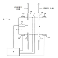
도 1a는 이온화 장치의 예를 도시한다.
도 1b는 이온화 장치의 다른 예를 도시한다.
도 2는 이온화 장치를 포함하는 검출기의 예를 도시한다.
도 3은 도 2의 장치의 동작 방법을 도시하는 흐름도를 도시한다.1A shows an example of an ionization apparatus.
1B shows another example of an ionization apparatus.
Figure 2 shows an example of a detector comprising an ionization device.
Figure 3 shows a flow chart illustrating the method of operation of the device of Figure 2;
도면에서, 동일한 구성 요소는 동일한 참조 번호를 나타내기 위해 사용된다.In the drawings, like elements are used to denote the same reference numerals.
본 발명의 실시예는 가스 유체의 샘플을 반응물 이온(reactant ion)과 조합함으로써 이러한 샘플을 이온화하는 방법 및 장치에 관한 것이다.An embodiment of the present invention is directed to a method and apparatus for ionizing such a sample by combining a sample of a gaseous fluid with a reactant ion.
본 발명의 일례는, 예를 들어 공기 및/또는 도펀트와 같은 가스 유체를 이온화함으로써 반응물 이온을 제공하도록 배치된 이온화기를 포함하는 이온화 장치이다. 이러한 장치는 또한 가스 유체의 샘플이 샘플을 이온화하기 위해 변경된 반응물 이온과 조합되기 전에 반응물 이온을 변경시키도록 구성된 이온 변경자(ion modifier)를 포함한다. 반응물 이온을 변경시킬지의 여부를 선택함으로써, 샘플과 혼합되는 반응물 이온의 타입은 변경될 수 있다. 이것은 원치 않는 간섭 이온의 생성이 억제되거나, 선택된 상이한 타입의 생성물 이온(product ion)이 동일한 가스 유체의 샘플로부터 얻어지도록 할 수 있다.An example of the present invention is an ionization apparatus comprising an ionizer disposed to provide reactant ions by ionizing a gaseous fluid, for example, air and / or a dopant. The apparatus also includes an ion modifier configured to alter the reactant ions before the sample of the gaseous fluid is combined with the reactant ions modified to ionize the sample. By choosing whether to change the reactant ion, the type of reactant ion to be mixed with the sample can be varied. This may inhibit the generation of unwanted interfering ions or cause selected different types of product ions to be obtained from a sample of the same gas fluid.
이러한 검출기에서 분석을 위해 상이한 기술이 샘플을 이온화하기 위해 사용될 수 있다. 자외선은 샘플을 직접 이온화하는 데 사용될 수 있다. 더욱 일반적으로, 샘플은, 먼저 코로나 방전 및 β 입자와 같은 이온화 방사선 소스를 사용하여 검출기 내의 공기로부터 이온을 생성시킨 다음, 이러한 이온이 샘플 분자와의 이온 분자 반응을 겪도록 허용하는 샘플과 이러한 이온을 혼합함으로써 간접적으로 이온화된다. 이러한 상황에서, 생성된 초기 이온은 반응물 이온이라고 부르며, 샘플 분자로부터 생성된 이온을 생성물 이온이라고 부른다. 또한, 도펀트라고 부르는 증기를 검출기에 부가함으로써, 초기 공기 이온에 의해 이온화되고, 그 다음 이러한 새로운 반응물 이온이 이온 분자 반응을 통해 샘플을 이온화하도록 하는 것이 유용할 수 있다. 이러한 방식으로, 샘플의 이온화의 화학 작용은 검출될 화합물을 우선적으로 이온화하고, 샘플 내의 일부 잠재적 간섭 화합물을 이온화시키지 않도록 제어될 수 있다. 이것은 이온이 달리 서로 구별하기 어려울 수 있는 물질을 식별하도록 할 수 있다Different techniques can be used to ionize the sample for analysis in these detectors. Ultraviolet light can be used to directly ionize the sample. More generally, a sample can be prepared by first generating ions from the air in the detector using an ionizing radiation source, such as a corona discharge and beta particles, and then providing a sample that allows such ions to undergo ionic molecular reactions with the sample molecules, Which is indirectly ionized. In this situation, the generated initial ions are called reactant ions, and the ions generated from the sample molecules are called product ions. It may also be useful to add ionized vapor to the detector, called a dopant, which is ionized by the initial air ions, and then allowing the new reactant ions to ionize the sample through ionic molecular reactions. In this way, the chemical action of the ionization of the sample can be controlled so as to preferentially ionize the compound to be detected and not ionize some potential interfering compounds in the sample. This allows ions to identify substances that may otherwise be difficult to distinguish from one another
실시예에서, 이온은 반응물 이온 생성 영역에서 생성되고, 전기장은 이온 변경 영역을 통해 샘플이 투여되는 반응 영역으로 통과하도록 배열된다. 도펀트 증기의 흐름은 반응물 이온 생성 영역에 투여될 수 있고, 도펀트 증기를 함유하지 않은 흐름은 변경 영역으로부터 도펀트 증기를 이동시키도록 구성됨으로써, 변경 영역 내의 도펀트 증기의 농도가 반응물 이온 생성 영역 내의 도펀트의 농도에 비해 감소되도록 할 수 있다. 변경 영역은 반응물 이온 생성 영역으로의 도펀트의 흐름과 반응 영역으로의 샘플의 흐름 사이에 위치된다. 일 실시예에서, 전기장은 반응물 이온 및/또는 변경된 반응물 이온을 반응 영역 내의 샘플로 이동시키도록 배열된다. 이온 게이트는 반응 영역으로부터 생성물 이온의 흐름을 제어하도록 제공될 수 있다.In an embodiment, the ions are generated in the reactant ion generating region and the electric field is arranged to pass through the ion changing region to the reaction region where the sample is administered. The flow of dopant vapor can be administered to the reactant ion generating region and the flow without dopant vapor can be configured to transfer the dopant vapor from the changing region such that the concentration of dopant vapor in the changing region is greater than the concentration of the dopant in the reactant ion generating region It can be made to be reduced compared to the concentration. The alteration region is located between the flow of the dopant to the reactant ion generating region and the flow of the sample to the reaction region. In one embodiment, the electric field is arranged to transfer reactant ions and / or modified reactant ions to a sample in the reaction zone. The ion gate may be provided to control the flow of product ions from the reaction region.
본 발명의 실시예는 또한 관심 물질을 검출하기 위한 검출 장치를 제공한다. 검출 장치는 검출기에 생성물 이온을 제공하는 샘플을 이온화하도록 구성되는 상술한 바와 같은 이온화 장치를 포함할 수 있다.Embodiments of the present invention also provide a detection device for detecting a substance of interest. The detection device may comprise an ionization device as described above configured to ionize a sample that provides product ions to the detector.
검출기는 이온 이동도 분광계 및/또는 질량 분광계를 포함할 수 있다.The detector may comprise an ion mobility spectrometer and / or a mass spectrometer.
실시예에서, 장치는 반응물 이온을 생성하고, 검출기에 의한 분석을 위한 생성물 이온을 생성하기 위해 샘플과 변경된 반응물 이온을 조합하기 전에 반응물 이온을 변경시키도록 구성된다.In an embodiment, the apparatus is configured to generate reactant ions and to modify the reactant ions prior to combining the sample with the altered reactant ions to produce product ions for analysis by the detector.
실시예에서, 장치는 제 1 생성물 이온을 생성하기 위해 반응물 이온과 샘플을 조합하고, 이러한 제 1 생성물 이온을 검출기에 제공하는 것에 기초하여 샘플을 분석하도록 제어될 수 있다. 그 다음, 장치는 반응물 이온을 얻고, 제 2 생성물 이온을 생성하기 위해 샘플과 변경된 반응물 이온을 조합하기 전에 반응물 이온을 변경시키도록 제어될 수 있다. 변경된 반응물 이온은 반응물 이온과 상이할 수 있으며, 예를 들어 이것은 상이한 구성 부분, 예를 들어 상이한 질량, 또는 상이한 화학적 성질, 예를 들어 상이한 에너지 성질을 가질 수 있다. 이온 변경자는 선택적으로 동작될 수 있으며, 예를 들어, 이온 변경자는 제 1 반응물 이온을 샘플과 조합하는 것으로부터 얻어진 검출기 신호에 기초하여 반응물 이온을 변경시키도록 동작될 수 있다. 일부 실시예에서, 제 2 이온 변경자는 생성물 이온을 변경시키기 위해 제공되고 배열될 수 있다.In an embodiment, the apparatus can be controlled to analyze the sample based on combining the sample with the reactant ions to produce a first product ion, and providing the first product ion to the detector. The apparatus can then be controlled to obtain reactant ions and alter the reactant ions prior to combining the sample with the modified reactant ions to produce the second product ions. The altered reactant ion may be different from the reactant ion, for example it may have different constituent parts, for example different masses, or different chemical properties, for example different energy properties. The ion modifier can be selectively operated, for example, the ion modifier can be operated to change the reactant ions based on detector signals obtained from combining the first reactant ions with the sample. In some embodiments, the second ion modifier may be provided and arranged to alter product ions.
도 1a는 이온화 장치(1)를 도시한다. 이온화 장치(1)는 반응물 이온 생성 영역(6), 이온 변경자(2) 및 반응 영역(8)을 포함한다.Fig. 1A shows an
반응물 이온 생성 영역(6)은 이온화기(12) 및 도펀트 증기를 도입하기 위한 제 1 유입구(14)를 포함할 수 있고, 제 1 배출구(16)를 포함할 수 있다. 도 1a에 도시된 예에서, 이온 변경자(2)는 반응 영역(8)으로부터 이온화기(12)를 분리하도록 배열된다. 반응 영역(8)은 샘플을 반응 영역으로 도입하기 위한 제 2 유입구(18)를 포함하고, 제 2 배출구(20)를 포함할 수 있다.The reactant ion generating region 6 may include an
도 1a에 도시된 바와 같이, 제어기(4)는 이온화기(12) 및 이온 변경자(2)와, 이온화기(12)로부터 이온 변경자(2)로 이온을 이동시키기 위해 전기장을 인가하도록 배치된 전기장 인가 장치(applier)(10)에 결합된다.1A, the
이온화기(12)는 반응물 이온 생성 영역(6)에 반응물 이온을 형성하기 위해 이온화 에너지를 인가하도록 동작할 수 있으며, 예를 들어 여기서 반응물 이온 생성 영역이 도펀트를 도입하기 위한 제 1 유입구를 포함하는 경우, 이온화기는 도펀트를 이온화함으로써 반응물 이온을 생성할 수 있고, 도펀트가 사용되지 않을 경우, 이온화기는 공기를 이온화함으로써 반응물 이온을 생성할 수 있다. 일부 실시예에서, 이온화기(12)는 코로나 방전 이온화기(12)를 포함하고, 이온화기(12)는 또한 β 입자와 같은 이온화 방사선의 방사성 선원(radioactive source)을 포함할 수 있다.The
이온 변경자(2)는, 예를 들어 이온의 유효 온도를 상승시킴으로써, 예를 들어 이온을 가열하고/하거나 이온을 교류 전기장(alternating electric field), 예를 들어 무선 주파수(RF) 전기장에 가해짐으로써 이온을 단편화(fragment)하도록 구성될 수 있다. 일부 예에서, 이온 변경자(2)는 2개의 전극을 포함한다. 이온 변경자(2)의 전극 사이의 영역은, 반응물 생성 영역(6)으로부터 반응 영역(8)으로 이동하기 위해, 반응물 이온이 교류 전기장에 가해질 수 있는 이온 변경 영역을 통과하도록 배열된 이온 변경 영역을 제공할 수 있다. 일례에서, 2개의 전극은 반응물 이온 생성 영역(6)으로부터 반응 영역(8)으로의 이온의 이동 방향으로 서로 이격될 수 있다. 이러한 전극은 각각 평면일 수 있고, 각각이 복수의 도체를 포함할 수 있으며, 이러한 도체는 예를 들어 그리드, 예를 들어 메시(mesh)와 같은 규칙적인 패턴으로 배치될 수 있다. 이온 변경자(2)는 히터를 포함할 수 있다.The
제 2 유입구(18)는 가스 유체 샘플을 이온화될 반응 영역(8)으로 통과시키도록 구성될 수 있다. 제 2 배출구(20)는 샘플이 이온 변경 영역으로 흐르는 것보다 우선적으로 반응 영역(8)에서 흐르도록 배치될 수 있다.The
제 1 유입구(14) 및 배출구(16)는 반응물 이온 생성 영역(6)을 통해 도펀트, 예를 들어 가스 유체의 흐름을 제공하도록 구성될 수 있다. 유입구 및 배출구는 이온화기(12) 주위에 도펀트의 흐름을 지향시키도록 배치될 수 있고, 또한 이온 변경자(2)로 흐르는 것보다 우선적으로 배출구에서 도펀트의 흐름을 지향시키도록 구성될 수 있다.The
전기장 인가 장치(10)는 이온 변경 영역을 통해 반응물 이온 생성 영역(8)으로부터 반응 영역(8)으로 반응물 이온을 이동시키도록 전기장을 인가하기 위해 배치된 전극을 포함할 수 있다.The
동작 중에, 도펀트, 예를 들어 가스 유체는 제 1 유입구(14)를 통해 반응물 이온 생성 영역(6)으로 도입될 수 있다. 그 다음, 제어기(4)는 이온화 에너지를 인가하여 반응물 이온을 제공하도록 이온화기(12)를 동작시킬 수 있다. 도펀트는 제 1 유입구(14)로부터 제 1 배출구(16)로 흐르는 도펀트의 흐름에서 반응물 이온 생성 영역(6)으로부터 수행될 수 있다. 이것은 반응물 이온 생성 영역(6)에서의 농도와 비교하여 이온 변경 영역에서의 도펀트의 농도를 감소시킬 수 있다. 제어기(4)는 이러한 도핑된 흐름과 상이한 방향으로, 예를 들어 전기장의 인가에 의한 흐름에 대해 횡 방향 또는 반대 방향으로 반응물 이온을 이동시키도록 전기장 인가 장치(10)를 제어할 수 있다. 실시예에서, 도펀트의 흐름은 도펀트와 조합한 변경된 반응물 이온으로부터 형성된 이온의 수를 선택된 임계 레벨 미만으로 감소시키도록 선택된다. 이를 수행하는 하나의 방식은 아래에 더욱 상세히 설명된다.In operation, a dopant, such as a gaseous fluid, may be introduced into the reactant ion generating region 6 through the
그 다음, 제어기(4)는 에너지, 예를 들어 교류 전기장 및/또는 열을 인가하도록 이온 변경자(2)를 동작시킬 수 있다. 이것은 이온 변경 영역에서 반응물 이온의 유효 온도를 상승시킬 수 있다. 이것은 반응물 이온을 단편화하고/하거나 첨가(adduct) 반응물 이온을 분리시킴으로써 반응물 이온을 변경시킬 수 있다. 제어기(4)는 변경되거나 변경되지 않은 반응물 이온을 제공하기 위해 이온 변경자(2)를 동작시킬지의 여부를 선택할 수 있다.The
그 다음, 변경되거나 변경되지 않은 반응물 이온은 이온 변경 영역으로부터 반응 영역(8)으로 이동될 수 있으며, 여기서 이러한 반응물 이온은 생성물 이온을 생성하기 위해 샘플을 이온화하도록 가스 유체의 샘플과 조합된다.The reactant ions, which have not been modified or modified, can then be transferred from the ion-exchange zone to the
본 발명과 관련하여 알 수 있는 바와 같이, 반응물 이온을 변경시키기 위해 이온 변경자(2)를 동작시킬지의 여부를 선택함으로써, 상이한 타입의 생성물 이온은 동일한 타입의 샘플 유체 및 동일한 도펀트 공급으로부터 제공될 수 있다. 이것은 생성물 이온이 샘플 유체를 분석할 목적으로 검출기에 제공될 수 있는 특별한 이점을 가질 수 있다.By choosing whether or not to operate the
실시예에서, 도 1a를 참조하여 설명된 것과 같은 이온화 장치는 달리 쉽게 이용할 수 없는 반응물 이온의 생성을 허용할 수 있다. 예를 들어, 본 경우의 발명자는 이온, NO2- 및 NO3-이 질산(HNO3)으로부터와 같이 도펀트 증기로부터 직접 생성하기 어려울 수 있음을 발견하였다.In an embodiment, an ionization device such as that described with reference to FIG. 1A may allow the production of reactant ions that are otherwise not readily available. For example, the present inventors have found that ions, NO 2 - and NO 3 - can be difficult to generate directly from dopant vapors, such as from nitric acid (HNO 3).
예를 들어, 질산 증기가 이온화되면, NOx- 이온은 이온화 프로세스에서 해리에 의해 형성될 수 있지만, 이것은 HNO3 분자로 첨가물을 형성할 수 있다. 실시예에서, 이러한 첨가물 이온(adduct ion)은 NOx- 이온만을 방출하기 위해 단편화될 수 있으며, 이는 그 후 반응 영역(8)으로 이동될 수 있다. NOx- 이온은 코로나 방전과 같은 다른 수단에 의해 생성될 수 있지만, 생성된 반응물 이온은 일반적으로 방전의 동작(전류, 전압, 치수(dimension)) 및 방전의 부근에서 방전의 생성물의 축적에 허용된 시간에 따라 다양한 양의 NO2 -, NO3 -, CO3 - 및 O3 - 이온의 혼합물이다. 이러한 반응물 이온의 혼합물은 샘플 내의 타겟 화합물의 존재에 대해 해석하기 어려운 복잡한 분석 데이터, 예를 들어 복잡한 이온 이동도 스펙트럼으로 이어진다. 본 발명과 관련하여, NOx는 본 명세서에서 단지 예로서 사용되었으며, 물론 다른 타입의 도펀트가 또한 사용될 수 있다는 것을 이해할 것이다.For example, when nitrate vapor is ionized, NOx - ions can be formed by dissociation in the ionization process, but this can form additives with HNO3 molecules. In an embodiment, such an additive ion can be fragmented to release only NO x - ions, which can then be transferred to the
도 1b는 제 2 이온화 장치를 도시한다. 도 1b에 도시된 장치는 도 1a를 참조하여 상술한 것과 유사하다. 그러나, 도 1b의 장치는 또한 이온 변경자(2) 주위에 퍼지 가스의 흐름을 제공하도록 배치된 퍼지 가스 제공자(30)를 포함한다. 이러한 퍼지 가스 제공자(30)는 전기장이 이온 변경자(2)를 통해 반응물 이온을 이동시키도록 허용하면서 도펀트 및 비이온화된 샘플과 같은 중성 종을 이온 변경자(2)로부터 멀리 이동시키도록 구성된다. 이것은 반응물 이온이 도펀트보다 우선적으로 변경 영역으로 이동되도록 할 수 있다. 예를 들어, 이러한 퍼지 가스의 흐름은 이온 변경 영역에 국한될 수 있고, 도펀트(및 샘플)가 예를 들어 그것을 옮기고/옮기거나 운반함으로써 이온 변경 영역으로 들어가는 경향을 감소시키도록 구성될 수 있으며, 예를 들어 퍼지 가스 제공자(30)는 이온 변경자(2)에 걸친 퍼지 가스의 흐름을 제공하도록 배치된 유입구 및 배출구를 포함할 수 있다.Figure IB shows a second ionization device. The apparatus shown in Figure 1B is similar to that described above with reference to Figure 1A. 1B also includes a
도 2는 도 1a 또는 도 1b를 참조하여 상술한 이온화 장치(1)와 같은 이온화 장치(1), 제어기(4) 및 검출기(24)를 포함하는 검출 장치(100)의 일례를 도시한다. 도 1a를 참조하여 상술한 바와 같이, 도 2에 도시된 이온화 장치(1)는 반응물 이온 생성 영역(6), 이온 변경 영역 및 반응 영역(8)을 포함할 수 있다. 도 2에 도시된 예에서, 검출기(24)는 반응 영역(8)을 통해 이온화 장치(1)에 결합된다. 이온 게이트는 반응 영역(8)과 검출기(24) 사이에 배치될 수 있고, 제 2 이온 변경자(22)는 이온 게이트와 검출기(24) 사이에 배치될 수 있다. 도 2에 도시된 전기장 인가 장치(10)는 또한 생성물 이온을 반응 영역(8)으로부터 검출기(24)로 이동시키도록 배치될 수 있다.FIG. 2 shows an example of a
도 2에 도시된 제어기(4)는 도 1a를 참조하여 상술한 제어기(4)와 동일한 방식으로 이온화 장치(1)에 결합될 수 있다. 또한, 도 2에 도시된 제어기(4)는 이온 게이트, 제 2 이온 변경자(22) 및 검출기(24)에 결합될 수 있다.The
이온화 장치(1)의 이온 변경자(2)와 마찬가지로, 제 2 이온 변경자(22)는 2개의 전극을 포함할 수 있으며, 이러한 2개의 전극은 이들 사이에 이온 변경 영역을 제공하도록 이격될 수 있다. 2개의 전극은 생성물 이온이 검출기(24)에 도달하도록 이온 변경 영역을 통과하도록 배치될 수 있다. 일례에서, 2개의 전극은 반응 영역(8)으로부터 검출기(24)로의 이온의 이동 방향으로 서로 이격될 수 있다. 이러한 전극은 각각 평면일 수 있고, 각각이 복수의 도체를 포함할 수 있으며, 이러한 도체는 예를 들어 그리드, 예를 들어 메시와 같은 규칙적인 패턴으로 배치될 수 있다. 제 2 이온 변경자(22)는 히터를 포함할 수 있다.Like the
이온 게이트는 이온이 반응 영역(8)으로부터 검출기(24)로 이동하는 것을 방지하도록 전기장을 제공하기 위해 이격되어 배치된 복수의 도체를 포함할 수 있다. 예를 들어, 이온 게이트는 예를 들어 동일 평면 구성으로 배치될 수 있는 교차 연결된(inter-digitated) 도체를 포함할 수 있다. 일부 실시예에서, 이온 게이트의 도체는 반응 영역으로부터 검출기로의 이온의 이동 방향으로 서로 오프셋될 수 있으며, 예를 들어 이온 게이트는 Tyndall-Powell 게이트를 포함할 수 있다. 이온 게이트는 반응 영역(8)으로부터 검출기(24)로의 생성물 이온의 통과를 제어하도록 동작할 수 있다. 이온 게이트의 도체는 도체가 상이한 전위에 있을 때 이온이 게이트를 통과할 수 없도록 배치될 수 있다. 그러나 도체가 동일한 전위에 있을 때, 도체에 부딪치지 않는 이온은 게이트를 통과할 수 있다. 이온 게이트는 Bradbury-Nielsen 게이트를 제공하도록 배치될 수 있다.The ion gate may comprise a plurality of conductors spaced apart to provide an electric field to prevent ions from moving from the
제 2 이온 변경자(22)는, 예를 들어, 생성물 이온을 단편화함으로써, 예를 들어 이러한 이온의 유효 온도를 상승시킴으로써, 예를 들어 이온을 가열하고/하거나 이온을 교류 전기장에 가함으로써 생성물 이온을 변경시키도록 동작할 수 있다.The
검출기(24)는 생성물 이온을 수용하도록 구성되고, 예를 들어 전자기장, 예를 들어 전기장 및/또는 자기장과의 생성물 이온의 상호 작용에 기초하여 관심 물질을 확인하기 위해 생성물 이온을 추가로 분석할 수 있다. 검출기(24)는 생성물 이온의 분석에 기초하여 신호를 제어기(4)에 제공하도록 구성될 수 있다. 일부 실시예에서, 검출기(24)는 이온 이동도 분광계의 이온 수집기를 포함하고, 일부 실시예에서 검출기(24)는 질량 분광계를 포함한다. 다른 타입의 검출기가 또한 사용될 수 있다.The
제어기(4)는 도 1a를 참조하여 상술한 바와 같이 가스 유체의 샘플로부터 생성물 이온을 얻기 위해 이온화 장치를 제어하도록 동작할 수 있다. 제어기(4)는 또한 반응물 이온을 변경할지의 여부를 결정하고, 반응물 이온이 변경되어야 하는 것으로 결정하는 경우에, 샘플과 조합되기 전에 반응물 이온을 변경하기 위해 이온 변경자를 제어하도록 동작할 수 있다. 제어기(4)는 가스 유체의 샘플의 분석에 기초하여 검출기(24)에 의해 제공된 신호에 기초하여 반응물 이온을 변경할지의 여부를 결정하도록 동작할 수 있다.The
동작 시에, 도 2에 도시된 검출 장치(100)는 일련의 사이클에서 동작될 수 있다. 제 1 동작 사이클에서, 제어기(4)는 가스 유체의 제 1 샘플로부터 제 1 생성물 이온을 제공하기 위해 이온화 장치를 동작시킬 수 있다. 제 1 생성물 이온은 반응물 이온을 변경시키기 위해 이온 변경자를 동작시키지 않고 생성될 수 있다. 그 후, 제어기(4)는 생성물 이온이 분석을 위해 검출기(24)로 이동되도록 허용하기 위해 이온 게이트를 제어할 수 있다. 검출기(24)는 제 1 생성물 이온을 분석하고, 제 1 생성물 이온의 분석에 기초한 제 1 신호를 제어기(4)에 제공할 수 있다. 예를 들어, 이러한 신호는 가스 유체에서의 관심 물질의 존재를 확인하기 위한 데이터를 포함할 수 있다.In operation, the
제 2 동작 사이클에서, 제어기(4)는 가스 유체의 제 2 샘플로부터 제 2 생성물 이온을 제공하기 위해 이온화 장치를 동작시킬 수 있다. 제 2 생성물 이온은 가스 유체의 제 2 샘플과 조합되기 전에 반응물 이온을 변경함으로써 생성될 수 있다. 그 후, 제어기(4)는 제 2 생성물 이온이 분석을 위해 검출기(24)로 이동되도록 허용하기 위해 이온 게이트를 제어할 수 있다. 검출기(24)는 제 2 생성물 이온을 분석하고, 제 2 생성물 이온의 분석에 기초한 제 2 신호를 제어기(4)에 제공할 수 있다. 그 후, 제어기(4)는 제 1 신호 및 제 2 신호에 기초한 가스 유체에서의 관심 물질의 존재를 확인할 수 있다. 추가의 동작 사이클에서, 제어기(4)는 관심 물질의 존재를 확인하기 위한 추가의 신호를 제공하도록 생성물 이온을 변경하기 위해 제 2 이온 변경자(22)를 동작시킬지의 여부를 결정할 수 있다.In a second operating cycle, the
실시예에서, 제어기(4)는 반응물 이온이 변경되거나 변경되지 않는 사이클과 생성물 이온이 변경되거나 변경되지 않는 사이클 사이에서 전환하도록 제 1 이온 변경자 및 제 2 이온 변경자(22)를 동작시킨다. 일부 실시예에서, 제어기(4)는 이온 변경자를 동작시키지 않을지를 결정하고, 그렇다면 어느 것을 동작시킬 것인지, 또는 검출기(24)로부터의 신호에 기초하여 둘 다를 동작시킬지를 결정하도록 구성될 수 있다. 예를 들어, 제어기(4)는 신호가 관심 물질의 존재를 나타내지만, 물질을 모호하지 않게 식별하기에 충분한 정보를 제공하지 않는 것으로 결정하면, 그것은 제 1 및/또는 제 2 이온 변경자(22)를 동작시킬 수 있다.In an embodiment, the
본 발명의 하나의 방법은 이제 도 3을 참조하여 설명될 것이다.One method of the present invention will now be described with reference to FIG.
도 3에 도시된 바와 같이, 도펀트가 제공되고(110), 이온화되어(112), 반응물 이온을 제공할 수 있다. 그 다음, 도펀트는 반응물 이온으로부터 적어도 부분적으로 분리되어(114), 반응물 이온 생성 영역에서의 농도에 비해 이온 변경 영역에서의 도펀트의 농도를 감소시킬 수 있다. 그 다음, 반응물 이온을 변경할지에 관한 선택(116)이 이루어질 수 있다. 그럴 경우, 반응물 이온은, 예를 들어 이의 유효 온도를 상승시킴으로써, 예를 들어, 이러한 이온을 단편화함으로써 변경된다(118). 그 다음, 변경된 반응물 이온(또는 경우에 따라 변경되지 않은 반응물 이온)은 생성물 이온을 제공하기 위해 샘플을 이온화하도록 가스 유체의 샘플과 조합될 수 있다(120).As shown in FIG. 3, a dopant may be provided 110 and ionized 112 to provide reactant ions. The dopant may then be at least partially separated (114) from the reactant ions to reduce the concentration of the dopant in the ion-change region relative to the concentration in the reactant ion-generating region. A
그 다음, 생성물 이온은 검출기에 제공될 수 있고(122), 그 다음, 생성물 이온을 변경시킬지 여부에 관한 선택(124)이 이루어질 수 있다. 그럴 경우, 반응물 이온은, 예를 들어 이의 유효 온도를 상승시킴으로써, 예를 들어, 이러한 이온을 단편화함으로써 변경된다(126). 그 다음, 변경되거나 변경되지 않은 생성물 이온은 검출기에 의해 분석될 수 있다(128, 130).The product ions may then be provided to the detector (122), and then a
일부 실시예에서, 장치는 반응물 이온을 도펀트보다 우선적으로 변경 영역으로 이동시키도록 구성된다. 예를 들어, 상술한 바와 같이, 반응물 이온 생성 영역을 통한 도펀트의 흐름은 반응물 이온 생성 영역으로부터 이온 변경자로의 도펀트의 통과를 방지하도록 선택될 수 있다. 예를 들어, 제 1 유입구(14) 및 제 1 배출구(16) 중 적어도 하나를 통한 체적 유량(volume flow rate)은 이것을 달성하도록 선택될 수 있다. 이것이 행해질 수 있는 하나의 방식은 도펀트의 흐름을 지향시키기 위해 제 1 유입구(14) 또는 제 1 배출구(16)의 단면 형상 또는 영역을 선택하는 것이다. 일부 예에서, 제 1 유입구(14) 및/또는 제 1 배출구(16)는 이온 변경자로의 도펀트의 통과를 방지하도록 선택된 경로를 따라 도펀트의 흐름을 지향시키도록 구성된다.In some embodiments, the apparatus is configured to transfer reactant ions to the change region preferentially over the dopant. For example, as discussed above, the flow of dopant through the reactant ion generating region may be selected to prevent the dopant from passing through the reactant ion generating region into the ion modifier. For example, the volume flow rate through at least one of the
실시예에서, 도펀트의 흐름은 도펀트 증기와 검출기에 의해 카운트된 변경된 반응물 이온 사이의 반응에 의해 형성된 이러한 이온의 수가 선택된 임계 레벨보다 작도록 선택된다. 이러한 임계 레벨은 검출기의 분해능 및/또는 신호 대 잡음비에 기초하여 선택될 수 있다. 이러한 임계 레벨은 또한 일상적인 실험에 기초하여, 예를 들어 도펀트와 반응되는 변경된 반응물 이온의 실험적으로 결정된 수용 가능한 레벨에 기초하여 선택될 수 있다(예를 들어, 시스템은 이러한 특정 이온 형성의 어떤 레벨을 용인하고(tolerate), 여전히 정확하게 동작할 수 있다). 예를 들어 첨가물 이온은 이온 변경자에 의해 변경된 도펀트와 반응물 이온 사이의 반응에 의해 형성된 이온을 포함할 수 있다. 이온 변경 영역에서 도펀트의 양을 제어하기 위해 도펀트의 흐름을 선택하는 하나의 방식은 이러한 첨가물 이온의 존재를 테스트하고, 유량, 흐름의 방향, 위치, 제 1 유입구(14), 제 1 배출구(16), 제 2 유입구(18) 및 제 2 배출구(20) 중 적어도 하나의 형상 및/또는 크기를 조정하는 것에 기초할 수 있다. 이러한 파라미터는 충분히 낮은 첨가물 이온 생성의 레벨을 달성하기 위해 테스트하는 것에 기초하여 선택될 수 있다. 이것에 접근하는 하나의 방식은 교정 절차를 수행하는 것이다. 이러한 교정은 도펀트 또는 샘플 중 어느 하나를 도입하지 않고 제 1 이온 이동도 스펙트럼(예를 들어, 플라즈마그램(plasmagram))을 얻기 위해 장치를 동작시키는 것을 포함할 수 있다. 그 다음, 이러한 스펙트럼은 도핑되지 않은 시스템에서 예상되는 이온과 다른 검출된 어떤 이온이 있는지(예를 들어 "깨끗한(clean)" 상태인지, 오염이 없는지)를 확인하도록 체크될 수 있다.In an embodiment, the flow of the dopant is selected such that the number of such ions formed by the reaction between the dopant vapor and the altered reactant ions counted by the detector is less than the selected threshold level. This threshold level can be selected based on the resolution of the detector and / or the signal-to-noise ratio. This threshold level can also be selected based on routine experimentation, for example based on an experimentally determined acceptable level of the reactant ions that are reacted with the dopant (e.g., Tolerate and still operate correctly). For example, the additive ions may comprise ions formed by the reaction between the dopant and the reactant ions modified by the ionic modifier. One way to select the dopant flow to control the amount of dopant in the ion change region is to test for the presence of such additive ions and to determine the flow rate, direction and location of the flow, the
이러한 체크는 다음과 같이 이루어질 수 있다:This check can be done as follows:
(1) 스펙트럼에서 지배적인 피크(dominant peak)를 찾고, 이것이 첨가된 도펀트가 없는 경우 클린 시스템에 존재할 것으로 예상되는 이온에 의해서만 형성된 피크라고 가정한다(이러한 이온의 예는 음이온 모드에서는 O2-·(H2O)n 및 양이온 모드에서는 H+·(H2O)n을 포함한다).(1) looking at the dominant peak (dominant peak) from the spectra, it is assumed that a peak is formed only by the ions that are expected to be present in the absence of the added dopant Clean system (examples of such ions in the negative ion mode O2 - · ( H2O) n in cationic mode and H +. (H2O) n in cationic mode.
(2) 이러한 피크와 연관된 이온 이동도 상수(ion mobility constant)를 결정하고, 감소된 이온 이동도 상수 Ko를 얻기 위해 온도 및 압력 변화를 보정한다.(2) determine ion mobility constants associated with these peaks, and correct temperature and pressure changes to obtain a reduced ion mobility constant K o .
(3) 지배적인 피크가 어떤 형태의 오염물로부터 보다는 오히려 어떤 첨가된 도펀트 또는 샘플이 없는 경우에 시스템에 존재하는 것으로 예상되는 이온으로부터 형성되는지를 Ko 값에 기초하여 결정한다.(3) Determine whether the dominant peak is formed from ions expected to be present in the system in the absence of any added dopant or sample, rather than from some form of contaminant, based on the K o value.
(4) 피크의 형상은 또한 예상되는 이온(예를 들어 오염물)과 유사한 Ko 값을 갖는 다른 이온 종의 존재에 대해 체크될 수 있다.(4) The shape of the peaks can also be checked for the presence of other ionic species with K o values similar to the expected ions (eg, contaminants).
(5) 선택한 레벨보다 큰 피크 크기, 예를 들어 지배적인 피크의 선택된 퍼센티지를 가진 스펙트럼에서 임의의 다른 피크의 존재를 체크한다. 이러한 임계값은 검출기의 분해능 및/또는 신호 대 잡음비에 기초하여 선택될 수 있다. 예를 들어, 임계값은 최소 분해 가능한 피크 크기에 기초할 수 있다. 이러한 임계값은 또한 실험적으로 결정된 수용 가능한 최소 레벨(예를 들어 허용 가능한 오염물의 레벨)에 기초하여 선택될 수 있다.(5) Check for the presence of any other peak in the spectrum with a peak size greater than the selected level, e.g., a selected percentage of dominant peaks. This threshold value can be selected based on the resolution and / or the signal-to-noise ratio of the detector. For example, the threshold may be based on a minimum resolvable peak size. This threshold value may also be selected based on an empirically determined acceptable minimum level (e.g., the level of acceptable contaminants).
그 다음, 도펀트는 반응물 이온 생성 영역에 제공될 수 있고, 제 2 이온 이동도 스펙트럼은 어떤 샘플을 반응 영역에 도입하지 않고 얻어질 수 있다. 제 1 이온 이동도 스펙트럼에서 확인된 "도핑되지 않은" 피크가 제 2 이온 이동도 스펙트럼에서 선택된 최소 레벨 미만이고, 예를 들어 검출될 수 없고, 관찰된 유일한 피크가 첨가된 도펀트를 이온화함으로써 얻어지는 관련된 이온이도록 도펀트의 농도는 선택될 수 있다. 이러한 선택된 최소 레벨은 첨가된 도펀트와 관련된 피크 높이의 크기의 일부, 예를 들어 피크의 크기의 1/100에 기초할 수 있다. 그 다음, 부가적인 도펀트의 동작 농도는 이러한 방식으로 "도핑되지 않은" 이온의 검출을 스웜프(swamp)하는데 필요한 첨가된 도펀트의 농도에 기초하여 결정될 수 있다. 동작 농도는 "도핑되지 않은" 피크를 선택된 최소 레벨 아래로 제공하는데 필요한 것 이상의 부가적인 도펀트의 초과량을 포함할 수 있다. 이러한 초과량은 몇 배 또는 심지어 열배 단위 또는 백배 단위 이상일 수 있다.The dopant can then be provided in the reactant ion generating region and the second ion mobility spectrum can be obtained without introducing any sample into the reaction region. The " undoped "peak identified in the first ion mobility spectrum is below the minimum level selected in the second ion mobility spectrum and can not be detected, for example, and the only peak observed can be obtained by ionizing the doped dopant. The concentration of the dopant can be selected to be an ion. This selected minimum level may be based on a fraction of the magnitude of the peak height associated with the added dopant, e.g., 1/100 of the magnitude of the peak. The operating concentration of the additional dopant may then be determined based on the concentration of the added dopant needed to swamp the detection of "undoped" ions in this manner. The operating concentration may include an excess amount of additional dopant beyond what is needed to provide a "undoped" peak below the selected minimum level. This excess amount may be several times or even ten times or more than ten times.
이러한 농도를 선택하면, 교정은 반응물 이온 생성 영역에서 도펀트의 흐름의 파라미터를 선택하는 것을 더 포함할 수 있다. 이러한 파라미터는 다음 중 적어도 하나를 포함할 수 있다:Choosing such a concentration, the calibration may further include selecting a parameter of the dopant flow in the reactant ion generating region. These parameters may include at least one of the following:
(a) 제 1 유입구(14)를 통한 반응물 이온 생성 영역으로의 도펀트의 유량;(a) the flow rate of the dopant to the reactant ion generating region through the
(b) 제 1 배출구(16)를 통한 반응물 이온 생성 영역에서의 도펀트의 유량;(b) the flow rate of the dopant in the reactant ion generating region through the
(c) 도펀트의 흐름 경로, 예를 들어 제 1 유입구 및/또는 제 1 배출구의 정렬, 형상, 위치 및/또는 방향.(c) the alignment, shape, location and / or orientation of the flow path of the dopant, e.g., the first inlet and / or the first outlet.
이러한 초기 파라미터를 선택하면, 교정은 선택된 도펀트의 농도 및 이러한 파라미터를 사용하여 제 3 이온 이동도 스펙트럼을 얻는 것과, 반응물 이온을 변경하지만 반응 영역에 임의의 샘플을 도입하지 않고 (반응물 이온 생성 영역과 반응 영역 사이에서) 이온 변경자를 동작시키는 것을 더 포함할 수 있다.By choosing these initial parameters, calibration can be accomplished by obtaining the concentration of the selected dopant and using these parameters to obtain a third ion mobility spectrum, and changing the reactant ions but without introducing any sample into the reaction zone Lt; RTI ID = 0.0 > a < / RTI > reaction zone).
변경되지 않은 잔류 반응물 이온이 (예를 들어, 상술한 선택된 최소 레벨보다 큰 레벨에서) 이러한 제 3 이온 이동도 스펙트럼에서 검출된다면, 도펀트는 일부 변경된 이온이 도펀트와 반응하는 농도로 이온 변경 영역에 존재한다는 것을 의미할 수 있다. 원래의 변경되지 않은 반응물 이온은 변경된 이온 또는 다른 종류의 이온으로부터 변형되었을 수 있다. 이것은 일부 실험에서 나타났다. 또한, 변경된 반응물 이온이 도펀트 증기와 반응할 시에 원래의 도핑된 반응물 이온과 상이한 이온 종을 형성하는 경우가 있을 수 있다. 따라서, 이러한 제 3 스펙트럼은 도핑된 반응물 피크의 존재뿐만 아니라 다른 이온과 관련된 다른 피크의 존재를 위해 검사될 수 있다.If the unchanged residual reactant ion is detected in this third ion mobility spectrum (e.g., at a level greater than the selected minimum level discussed above), the dopant will be present in the ion-altering region at a concentration at which some altered ions will react with the dopant . The original unaltered reactant ions may have been modified from altered ions or other types of ions. This appeared in some experiments. It may also be the case that the modified reactant ion forms an ionic species different from the originally doped reactant ion when reacting with the dopant vapor. Thus, this third spectrum can be examined for the presence of doped reactant peaks as well as for the presence of other peaks associated with other ions.
(도펀트와 관련이 있든 없든) 원하지 않는 이온이 이온 이동도 스펙트럼에서 검출되면, (위에 열거된) 흐름의 파라미터 중 하나 이상이 달라질 수 있고, 원하지 않는 이온의 레벨이 수용 가능한 레벨(예를 들어, 상술한 선택된 최소 레벨 미만)에 도달할 때까지 부가적인 스펙트럼이 획득될 수 있다.If undesired ions are detected in the ion mobility spectrum (whether or not associated with a dopant), one or more of the parameters of the flow (listed above) may be different, and the level of undesired ions may be at an acceptable level (e.g., Less than the above selected minimum level) can be obtained.
동일한 교정 프로세스가 반응 영역으로의 샘플의 흐름을 선택하는데 사용될 수 있다. 예를 들어, 반응 영역으로의 샘플의 흐름을 제어하는 파라미터가 선택될 수 있으며, 이러한 파라미터는 다음 중 적어도 하나를 포함할 수 있다:The same calibration process can be used to select the flow of samples to the reaction zone. For example, a parameter that controls the flow of the sample to the reaction zone may be selected, and this parameter may include at least one of the following:
(a) 제 2 유입구(18)를 통한 반응 영역으로의 샘플의 유량;(a) the flow rate of the sample through the
(b) 제 2 배출구(20)를 통한 반응 영역에서의 유량;(b) the flow rate in the reaction zone through the
(c) 샘플의 흐름 경로, 예를 들어 제 2 유입구 및/또는 제 2 배출구의 정렬, 형상, 위치 및/또는 방향.(c) the alignment, shape, position and / or orientation of the flow path of the sample, for example the second inlet and / or the second outlet.
본 발명과 관련하여, 이러한 교정 방법은 장치의 검출기가 이온 이동도 분광계를 포함하는 경우, 및 또한 검출기가 질량 분광계, 예를 들어 조합된 이온 이동도 분광계 및 질량 분광계(IMS-MS) 검출기를 포함하는 경우에 사용될 수 있다는 것이 이해될 것이다.In the context of the present invention, such a calibration method includes the case where the detector of the apparatus comprises an ion mobility spectrometer and also the detector comprises a mass spectrometer, for example a combined ion mobility spectrometer and mass spectrometer (IMS-MS) detector It will be understood that the present invention can be used in the following cases.
실시예에서, 이온 변경이 불완전할 수 있는 가능성을 제어하기 위해, 본 발명의 이온화 장치는 예를 들어 퍼지 가스 내에서(예를 들어 이온이 반응물 이온 생성 영역에서 도펀트로부터 생성되지 않고, 반응물 이온 생성 영역으로의 도펀트의 흐름의 존재에서) 이온이 변경 영역에만 주입되도록 구성될 수 있다. 원하지 않는 이온이 검출되면, 그것은 이온 변경 영역에서의 도펀트의 존재로부터 있는 것으로 추정될 수 있다. 이러한 접근 방식의 이점은 100% 미만의 변경 효율로 인해 혼란이 없다는 것, 즉 변경자가 동작되지 않는다는 것이다. 이러한 방식은 모든 자체 문제를 가지며, 다른 테스트 방식이 고려될 수 있음을 보여주기 위해서만 본 명세서에 포함되었다.In an embodiment, to control the likelihood that the ion change may be incomplete, the ionization apparatus of the present invention may be used, for example, in a purge gas (e.g., where ions are not generated from the dopant in the reactant ion generating region, In the presence of a flow of dopant into the region). If an unwanted ion is detected, it can be assumed that it is from the presence of a dopant in the ion-altering region. An advantage of this approach is that there is no confusion due to less than 100% change efficiency, i.e. the modifier is not working. This approach has its own problems and is included herein only to show that other test methods can be considered.
교정 방법은 다양한 환경 조건(특히 온도 및 압력) 하에서 반복될 수 있으며, 또한 도펀트의 농도가 환경 조건에 따라 다를 수 있기 때문에 사용된 도펀트의 타입마다 반복될 수 있다.The calibration method can be repeated under various environmental conditions (especially temperature and pressure) and can be repeated for each type of dopant used since the concentration of the dopant can vary depending on the environmental conditions.
본 발명의 다른 예 및 변형은 본 발명과 관련하여 당업자에게 명백할 것이며, 예를 들어, 도 1a를 참조하여 설명된 실시예, 및 도 2를 참조하여 설명된 실시예의 제어기(4)는 또한 이온화기(12) 및 이온 변경자 및/또는 이온 게이트의 동작의 타이밍을 제어함으로써, 이들의 동작이 동기화되도록, 예를 들어 이들이 동시에 동작되도록 구성될 수 있어, 예를 들어 이들의 동작의 타이밍이 중첩하거나 동시에 시작하고/하거나 종료한다. 예를 들어, 제어기(4)는 이온화 에너지의 펄스를 인가하기 위해 이온화기(12)를 동작시키고, 이러한 펄스의 타이밍에 기초하여 이온을 변경시키기 위해 이온 변경자를 동작시키도록 구성될 수 있다. 예를 들어, 제어기(4)는, 이온화기(12)에 인가된 펄스와 동시에, 또는 이온화기의 동작으로부터 지연된 어떤 시간에 시작 및/또는 종료 중에 교류 전기장 및/또는 열 에너지를 인가하기 위해 이온 변경자를 제어하도록 구성될 수 있다. 마찬가지로, 제어기(4)는 이온화기(12) 및/또는 이온 변경자의 동작 타이밍에 기초하여 이온 게이트를 개방할 시간을 선택하도록 구성될 수 있다.Other embodiments and variations of the present invention will be apparent to those skilled in the art in light of the present invention, for example, the embodiment described with reference to FIG. 1A, and the
일반적으로 도면을 참조하면, 개략적인 기능 블록도가 본 명세서에 설명된 시스템 및 장치의 기능을 나타내기 위해 사용되는 것으로 이해될 것이다. 그러나, 기능이 이러한 방식으로 분할될 필요는 없으며, 아래에서 설명되고 청구된 것과 다른 임의의 특정 하드웨어의 구조체를 암시하는 것으로 취해지지 않아야 하는 것으로 이해될 것이다. 도면에 도시된 요소 중 하나 이상의 기능은 본 발명의 장치 전체에 걸쳐 더 세분되고 및/또는 분산될 수 있다. 일부 실시예에서, 도면에 도시된 하나 이상의 요소의 기능은 단일 기능 유닛으로 통합될 수 있다.Referring generally to the drawings, it will be appreciated that schematic functional block diagrams are used to describe the functionality of the system and apparatus described herein. It will be appreciated, however, that the functionality need not be partitioned in this manner, and should not be taken to imply any particular hardware structure that is different from what is described and claimed below. The functionality of one or more of the elements shown in the figures may be further subdivided and / or distributed throughout the apparatus of the present invention. In some embodiments, the functionality of one or more of the elements shown in the figures may be incorporated into a single functional unit.
상술한 실시예는 예시적인 예로서 이해되어야 한다. 추가의 실시예가 고려된다. 임의의 일 실시예와 관련하여 설명된 임의의 특징은 단독으로 또는 설명된 다른 특징과 조합하여 사용될 수 있고, 또한 임의의 다른 실시예의 하나 이상의 특징 또는 임의의 다른 실시예의 임의의 조합과 함께 사용될 수 있다. 더욱이, 상술하지 않은 등가물 및 수정이 또한 첨부된 청구 범위에 규정된 본 발명의 범위를 벗어나지 않고 사용될 수 있다.The above-described embodiments are to be understood as illustrative examples. Additional embodiments are contemplated. Any feature described in connection with any one embodiment may be used alone or in combination with other features described and may also be used with any combination of one or more features of any other embodiment or any other embodiment have. Moreover, equivalents and modifications not described above may also be used without departing from the scope of the invention as set forth in the appended claims.
일부 예에서, 하나 이상의 메모리 요소는 본 명세서에 설명된 동작을 구현하는데 사용되는 데이터 및/또는 프로그램 명령어를 저장할 수 있다. 본 발명의 실시예는 본 명세서에 설명되고/되거나 청구된 방법 중 임의의 하나 이상을 수행하는 프로세서를 프로그램하고/하거나, 본 명세서에 설명되고/되거나 청구된 바와 같은 데이터 처리 장치를 제공하도록 동작 가능한 프로그램 명령어를 포함하는 유형의 비일시적 저장 매체를 제공한다.In some instances, one or more memory elements may store data and / or program instructions used to implement the operations described herein. Embodiments of the invention may also be practiced in the art, either by programming a processor that performs any one or more of the methods described and / or claimed herein, or may be operable to provide data processing apparatus as described and / A non-volatile storage medium of the type comprising program instructions.
본 명세서에 개략적으로 도시된 제어기와 같은 활동 및 장치는 로직 게이트의 어셈블리와 같은 고정된 로직, 또는 프로세서에 의해 실행되는 소프트웨어 및/또는 컴퓨터 프로그램 명령어와 같은 프로그램 가능한 로직으로 구현될 수 있다. 다른 종류의 프로그램 가능한 로직은 프로그램 가능한 프로세서, 프로그램 가능한 디지털 로직(예 : FPGA(field programmable gate array), EPROM(erasable programmable read only memory), EEPROM(electrically erasable programmable read only memory), ASIC(application specific integrated circuit), 또는 임의의 다른 종류의 디지털 로직, 소프트웨어, 코드, 전자 명령어, 플래시 메모리, 광학 디스크, CD-ROM, DVD ROM, 자기 또는 광학 카드, 전자 명령어를 저장하기에 적합한 다른 타입의 머신 판독 가능한 매체, 또는 이의 임의의 적절한 조합을 포함한다.Actions and devices, such as the controller schematically illustrated herein, may be implemented in fixed logic, such as an assembly of logic gates, or in programmable logic, such as software and / or computer program instructions, executed by a processor. Other types of programmable logic include programmable processors, programmable digital logic (e.g., field programmable gate array (FPGA), erasable programmable read only memory (EPROM), electrically erasable programmable read only memory (EEPROM) or any other type of digital logic, software, code, electronic instructions, flash memory, optical disks, CD-ROMs, DVD ROMs, magnetic or optical cards, Media, or any suitable combination thereof.
Claims (24)
반응물 이온을 제공하도록 구성된 이온화기;
상기 반응물 이온을 변경시키도록 구성된 이온 변경자, 및
변경된 반응물 이온 및 샘플을 수용하고, 상기 샘플에서 관심 물질을 확인하도록 구성된 검출기에 의한 분석을 위해 상기 샘플을 이온화하기 위해 상기 샘플을 상기 변경된 반응물 이온과 조합하도록 배치된 반응 영역을 포함하는 장치.An ionization apparatus for ionizing a sample of a gaseous fluid,
An ionizer configured to provide reactant ions;
An ion modifier configured to alter the reactant ion, and
And a reaction zone arranged to receive the modified reactant ions and sample and to combine the sample with the modified reactant ions to ionize the sample for analysis by a detector configured to identify the substance of interest in the sample.
상기 이온화기를 지나서 도펀트의 흐름을 제공하도록 배치된 도펀트 흐름 제공자, 및 상기 이온 변경자로의 상기 흐름에서 반응물 이온을 이동시키도록 배치된 전기장 인가 장치를 포함하는 장치.The method according to claim 1,
A dopant flow provider disposed to provide a flow of dopant past the ionizer, and an electric field application device arranged to transfer reactant ions in the flow to the ion modifier.
생성물 이온을 제공하기 위해 샘플을 이온화하도록 구성된 제 1 항 또는 제 2 항에 따른 이온화 장치;
상기 이온화 장치에 의해 생성된 상기 생성물 이온을 분석하는 것에 기초하여 관심 물질을 검출하도록 구성된 검출기; 및
상기 생성물 이온을 상기 검출기로 이동시키도록 배치된 전기장 인가 장치를 포함하는 장치.A detection device for detecting a substance of interest,
An ionization apparatus according to claims 1 or 2, configured to ionize a sample to provide product ions;
A detector configured to detect a substance of interest based on analyzing the product ions produced by the ionization apparatus; And
And an electric field application device arranged to move the product ions to the detector.
상기 이온 변경자는 상기 이온화기와 상기 반응 영역 사이에 배치되는 장치.4. The method according to any one of claims 1 to 3,
Wherein the ion modifier is disposed between the ionizer and the reaction zone.
상기 이온 변경자는 반응물 이온을 교류 전기장에 가하도록 구성되는 장치.5. The method according to any one of claims 1 to 4,
Wherein the ion modifier is configured to apply reactant ions to an alternating electric field.
반응물 이온을 생성하도록 상기 이온화기를 동작시키고, 상기 이온 변경자의 동작의 타이밍이 상기 이온화기의 동작의 타이밍에 기초하여 선택되도록 상기 이온 변경자를 동작시키기 위해 구성된 제어기를 포함하는 장치.6. The method according to any one of claims 1 to 5,
And a controller configured to operate the ionizer to produce reactant ions and to operate the ion modifier such that the timing of operation of the ion modifier is selected based on the timing of operation of the ionizer.
상기 반응 영역에서의 생성물 이온의 통과를 제어하도록 배치된 이온 게이트를 포함하고, 상기 제어기는 상기 이온화기 및 상기 이온 변경자 중 적어도 하나의 상기 동작의 타이밍에 기초하여 상기 이온 게이트의 상기 동작의 타이밍을 제어하도록 구성되는 장치.The method according to claim 6,
Wherein the controller is configured to control the timing of the operation of the ion gate based on the timing of the operation of at least one of the ionizer and the ion modifier, Gt;
상기 도펀트 흐름 제공자는 제 1 방향으로 도펀트 흐름을 제공하도록 구성되고, 상기 전기장 인가 장치는 상기 제 1 방향과 상이한 제 2 방향으로 상기 변경 영역을 향해 상기 반응물 이온을 이동시키도록 구성되는 장치.8. The method according to any one of claims 3 to 7,
Wherein the dopant flow provider is configured to provide a dopant flow in a first direction and the electric field application device is configured to move the reactant ions toward the change region in a second direction different from the first direction.
상기 반응 영역으로보다는 상기 이온 변경자로의 퍼지 가스의 더 큰 흐름을 제공하기 위해 상기 이온 변경자에 걸쳐 퍼지 가스의 흐름을 제공하도록 배치된 퍼지 가스 제공자를 포함하는 장치.9. The method according to any one of claims 1 to 8,
And a purge gas provider arranged to provide a flow of purge gas across the ion modifier to provide a greater flow of purge gas to the ion modifier than to the reaction region.
상기 제어기는 상기 검출기로부터의 신호에 기초하여 상기 이온 변경자를 동작시키도록 구성되는 장치.10. A method according to any one of claims 4 to 9,
And the controller is configured to operate the ion modifier based on a signal from the detector.
상기 검출기는 이온 이동도 분광계 및 질량 분광계 중 하나를 포함하는 장치.11. The method according to any one of claims 4 to 10,
Wherein the detector comprises one of an ion mobility spectrometer and a mass spectrometer.
반응물 이온을 제공하기 위해 도펀트를 이온화하는 단계;
상기 반응물 이온을 변경시키는 단계; 및
상기 가스 유체를 이온화하기 위해 상기 샘플과 변경된 반응물 이온을 조합시키는 단계를 포함하는 방법.A method of ionizing a gas fluid,
Ionizing the dopant to provide reactant ions;
Altering the reactant ions; And
And combining the sample with the modified reactant ions to ionize the gaseous fluid.
생성물 이온을 제공하기 위해 제 12 항에 따른 방법에 의해 상기 샘플을 이온화하는 단계,
상기 생성물 이온을 검출기로 이동시키도록 전기장을 인가하는 단계, 및
관심 물질을 검출하기 위한 상기 검출기로의 상기 생성물 이온의 이동에 기초하여 상기 생성물 이온을 분석하는 단계를 포함하는, 샘플을 분석하는 방법.In a method for analyzing a sample,
Ionizing the sample by a method according to claim 12 to provide product ions,
Applying an electric field to move the product ions to a detector, and
And analyzing the product ions based on the movement of the product ions to the detector for detecting a substance of interest.
상기 도펀트보다 우선적으로 반응물 이온을 상기 변경 영역으로 이동시키는 단계를 포함하는, 샘플을 분석하는 방법.The method according to claim 12 or 13,
And shifting reactant ions to the alteration region prior to the dopant.
상기 반응물 이온을 변경시키는 단계는 상기 반응물 이온의 유효 온도를 상승시키는 단계를 포함하는, 샘플을 분석하는 방법.15. The method according to any one of claims 12 to 14,
Wherein altering the reactant ion comprises raising the effective temperature of the reactant ion.
상기 반응물 이온의 유효 온도를 상승시키는 단계는 상기 반응물 이온을 교류 전기장에 가하는 것, 및 상기 반응물 이온을 가열하는 것 중 적어도 하나를 포함하는, 샘플을 분석하는 방법.16. The method of claim 15,
Wherein the step of raising the effective temperature of the reactant ion comprises at least one of applying the reactant ion to an alternating electric field and heating the reactant ion.
상기 도펀트는 이온화 에너지의 펄스에 의해 이온화되고, 상기 교류 전기장은 상기 이온화 에너지의 펄스의 시간으로부터 지연된 시간에 있도록 타이밍되는, 샘플을 분석하는 방법.17. The method of claim 16,
Wherein the dopant is ionized by a pulse of ionizing energy and the alternating electric field is timed to be at a delayed time from the time of the pulse of the ionizing energy.
상기 도펀트에 대한 반응물 이온의 농도를 증가시키는 단계는 도펀트를 제 1 방향으로 이동시키는 단계, 및 상기 반응물 이온을 상기 이온 변경자를 향한 제 2 방향으로 이동시키는 단계를 포함하며, 상기 제 2 방향은 상기 제 1 방향과 상이한, 샘플을 분석하는 방법.18. The method according to any one of claims 14 to 17,
Wherein increasing the concentration of reactant ions to the dopant comprises moving the dopant in a first direction and moving the reactant ions in a second direction toward the ion modifier, Wherein the first direction is different from the first direction.
상기 도펀트는 반응물 이온 생성 영역에서 이온화되고, 상기 도펀트를 제 1 방향으로 이동시키는 단계는 상기 반응물 이온 생성 영역에서의 도펀트의 흐름을 제공하는 단계를 포함하는, 샘플을 분석하는 방법.18. The method of claim 17,
Wherein the dopant is ionized in a reactant ion generating region and moving the dopant in a first direction comprises providing a flow of dopant in the reactant ion generating region.
상기 반응물 이온을 상기 제 2 방향으로 이동시키는 단계는 상기 반응물 이온을 상기 변경 영역으로 이동시키도록 구성된 전기장에 상기 반응물 이온을 가하는 단계를 포함하는, 샘플을 분석하는 방법.20. The method according to claim 18 or 19,
Wherein moving the reactant ions in the second direction comprises applying the reactant ions to an electric field configured to move the reactant ions to the change region.
상기 이온 변경자에 걸친 퍼지 가스의 흐름을 제공하는 단계를 포함하며, 상기 퍼지 가스의 흐름은 상기 반응 영역에서보다 상기 이온 변경 영역에서 더 큰, 샘플을 분석하는 방법.20. The method according to any one of claims 11 to 19,
Providing a flow of purge gas across the ion modifier wherein the flow of purge gas is greater in the ion change region than in the reaction region.
가스 유체의 샘플을 이온화하기 위한 이온화 장치의 반응물 이온 생성 영역을 통해 도펀트의 흐름을 제공하는 단계;
반응물 이온을 제공하기 위해 상기 도펀트를 이온화하는 단계;
상기 반응물 이온을 변경시키기 위해 이온 변경자를 동작시키는 단계로서, 상기 이온 변경자는 상기 반응물 이온 생성 영역과 상기 이온화 장치의 반응 영역 사이에 배치되는 상기 동작시키는 단계;
원하지 않는 이온이 상기 이온 변경자로부터 얻어지는지를 결정하는 단계; 및
원하지 않는 이온이 얻어지는 경우에, 원하지 않는 이온의 생성을 줄이기 위해 도펀트의 흐름을 조절하는 단계를 포함하는, 교정 방법.In the calibration method,
Providing a flow of dopant through a reactant ion generating region of an ionizer for ionizing a sample of a gaseous fluid;
Ionizing the dopant to provide reactant ions;
Operating the ion modifier to change the reactant ion, wherein the ion modifier is disposed between the reactant ion generating region and the reaction region of the ionizing apparatus;
Determining whether unwanted ions are obtained from the ion modifier; And
And adjusting the flow of the dopant to reduce the generation of undesired ions, if unwanted ions are obtained.
상기 도펀트의 흐름을 조절하는 단계는,
(a) 상기 반응물 이온 생성 영역으로의 도펀트의 유량;
(b) 상기 반응물 이온 생성 영역에서의 도펀트의 유량; 및
(c) 상기 도펀트의 흐름 경로, 예를 들어 제 1 유입구 및/또는 제 1 배출구의 정렬, 형상, 위치 및/또는 방향 중 적어도 하나를 조절하는 단계를 포함하는, 교정 방법.23. The method of claim 22,
Wherein adjusting the flow of the dopant comprises:
(a) a flow rate of a dopant to the reactant ion generating region;
(b) the flow rate of the dopant in the reactant ion generating region; And
(c) adjusting at least one of the alignment, shape, position and / or orientation of the flow path of the dopant, e.g., the first inlet and / or the first outlet.
Applications Claiming Priority (3)
| Application Number | Priority Date | Filing Date | Title |
|---|---|---|---|
| GB1413236.9 | 2014-07-25 | ||
| GBGB1413236.9A GB201413236D0 (en) | 2014-07-25 | 2014-07-25 | Method and apparatus |
| PCT/GB2015/052116 WO2016012787A1 (en) | 2014-07-25 | 2015-07-22 | Method and apparatus for the chemical ionization of samples |
Publications (2)
| Publication Number | Publication Date |
|---|---|
| KR20170036012A true KR20170036012A (en) | 2017-03-31 |
| KR102477769B1 KR102477769B1 (en) | 2022-12-14 |
Family
ID=51587257
Family Applications (1)
| Application Number | Title | Priority Date | Filing Date |
|---|---|---|---|
| KR1020177004971A KR102477769B1 (en) | 2014-07-25 | 2015-07-22 | Method and apparatus for the chemical ionization of samples |
Country Status (11)
| Country | Link |
|---|---|
| US (2) | US9953823B2 (en) |
| EP (2) | EP3172759B1 (en) |
| JP (1) | JP6788572B2 (en) |
| KR (1) | KR102477769B1 (en) |
| CN (1) | CN106716593B (en) |
| CA (1) | CA2956238C (en) |
| GB (3) | GB201413236D0 (en) |
| MX (2) | MX2017001169A (en) |
| PL (1) | PL3172759T3 (en) |
| RU (1) | RU2696088C2 (en) |
| WO (1) | WO2016012787A1 (en) |
Families Citing this family (1)
| Publication number | Priority date | Publication date | Assignee | Title |
|---|---|---|---|---|
| GB201413236D0 (en) * | 2014-07-25 | 2014-09-10 | Smiths Detection Watford Ltd | Method and apparatus |
Citations (4)
| Publication number | Priority date | Publication date | Assignee | Title |
|---|---|---|---|---|
| US5892364A (en) * | 1997-09-11 | 1999-04-06 | Monagle; Matthew | Trace constituent detection in inert gases |
| US6888132B1 (en) * | 2002-06-01 | 2005-05-03 | Edward W Sheehan | Remote reagent chemical ionization source |
| US20070102634A1 (en) * | 2005-11-10 | 2007-05-10 | Frey Brian L | Electrospray ionization ion source with tunable charge reduction |
| JP2013541130A (en) * | 2010-08-19 | 2013-11-07 | レコ コーポレイション | Mass spectrometer with soft ionization glow discharge and regulator |
Family Cites Families (22)
| Publication number | Priority date | Publication date | Assignee | Title |
|---|---|---|---|---|
| US4005291A (en) * | 1972-01-04 | 1977-01-25 | Massachusetts Institute Of Technology | Ionization method for mass spectrometry |
| JPS5440369A (en) * | 1977-09-05 | 1979-03-29 | Senichi Masuda | Particle charging device |
| US5218203A (en) * | 1991-03-22 | 1993-06-08 | Georgia Tech Research Corporation | Ion source and sample introduction method and apparatus using two stage ionization for producing sample gas ions |
| TW503263B (en) * | 1997-12-03 | 2002-09-21 | Matsushita Electric Works Ltd | Plasma processing apparatus and method |
| JP4802104B2 (en) * | 2003-11-25 | 2011-10-26 | サイオネックス コーポレイション | Mobility-based apparatus and method using dispersion characteristics, sample dissociation and / or pressure control to improve sample analysis |
| US8668873B2 (en) * | 2005-02-02 | 2014-03-11 | The Florida International University Board Of Trustees | Method and apparatus for extraction, detection, and characterization of vapors from explosives, taggants in explosives, controlled substances, and biohazards |
| JP5193880B2 (en) | 2006-01-02 | 2013-05-08 | エクセリムス コーポレイション | Apparatus and method for multidimensional ion mobility spectrometry |
| GB0704137D0 (en) | 2007-03-03 | 2007-04-11 | Smiths Detection Watford Ltd | Ion mobility spectrometers |
| GB0704547D0 (en) * | 2007-03-09 | 2007-04-18 | Smiths Detection Watford Ltd | Ion mobility spectrometers |
| WO2009018305A1 (en) * | 2007-07-30 | 2009-02-05 | Particle Measuring Systems, Inc. | Detection of analytes using ion mobility spectrometry |
| US8334505B2 (en) * | 2007-10-10 | 2012-12-18 | Mks Instruments, Inc. | Chemical ionization reaction or proton transfer reaction mass spectrometry |
| KR101260631B1 (en) * | 2007-10-10 | 2013-05-06 | 엠케이에스 인스트루먼츠, 인코포레이티드 | Chemical ionization reaction or proton transfer reaction mass spectrometry with a quadrupole or time-of-flight mass spectrometer |
| CN202172060U (en) | 2008-05-30 | 2012-03-21 | 珀金埃尔默健康科学股份有限公司 | Apparatus used for ionization chemical species |
| WO2010104981A2 (en) * | 2009-03-10 | 2010-09-16 | University Of Maryland Biotechnology Institute | Deuterium isobaric tag reagents for quantitative analysis |
| EP2780930A4 (en) | 2011-11-15 | 2015-07-22 | Univ Helsinki | Method and device for determining properties of gas phase bases or acids |
| KR102139986B1 (en) * | 2012-02-16 | 2020-08-11 | 스미스 디텍션-워트포드 리미티드 | Synchronised ion modification |
| US9123520B2 (en) * | 2012-04-02 | 2015-09-01 | Battelle Memorial Institute | Method for selective detection of explosives in mass spectrometer or ion mobility spectrometer at parts-per-quadrillion level |
| GB201208733D0 (en) | 2012-05-18 | 2012-07-04 | Micromass Ltd | Excitation of reagent molecules within a rf confined ion guide or ion trap to perform ion molecule, ion radical or ion-ion interaction experiments |
| GB201307141D0 (en) | 2013-04-19 | 2013-05-29 | Johnson & Starley | Heating appliance |
| EP2796868B1 (en) * | 2013-04-24 | 2015-09-09 | Bruker Daltonik GmbH | Ion mobility spectrometer with device for generating ammonia gas |
| DE102013114421B4 (en) * | 2013-12-19 | 2016-02-18 | Gottfried Wilhelm Leibniz Universität Hannover | Gas analysis device and method for gas analysis |
| GB201413236D0 (en) * | 2014-07-25 | 2014-09-10 | Smiths Detection Watford Ltd | Method and apparatus |
-
2014
- 2014-07-25 GB GBGB1413236.9A patent/GB201413236D0/en not_active Ceased
-
2015
- 2015-07-22 JP JP2017504374A patent/JP6788572B2/en active Active
- 2015-07-22 US US15/329,147 patent/US9953823B2/en active Active
- 2015-07-22 RU RU2017103986A patent/RU2696088C2/en active
- 2015-07-22 WO PCT/GB2015/052116 patent/WO2016012787A1/en active Application Filing
- 2015-07-22 CN CN201580051142.3A patent/CN106716593B/en active Active
- 2015-07-22 CA CA2956238A patent/CA2956238C/en active Active
- 2015-07-22 EP EP15744641.0A patent/EP3172759B1/en active Active
- 2015-07-22 PL PL15744641.0T patent/PL3172759T3/en unknown
- 2015-07-22 EP EP23183153.8A patent/EP4239329A3/en active Pending
- 2015-07-22 MX MX2017001169A patent/MX2017001169A/en unknown
- 2015-07-22 KR KR1020177004971A patent/KR102477769B1/en active IP Right Grant
- 2015-07-27 GB GB1800874.8A patent/GB2556256B/en active Active
- 2015-07-27 GB GB1513190.7A patent/GB2532540B/en active Active
-
2017
- 2017-01-25 MX MX2023006071A patent/MX2023006071A/en unknown
-
2018
- 2018-03-15 US US15/922,377 patent/US10607827B2/en active Active
Patent Citations (4)
| Publication number | Priority date | Publication date | Assignee | Title |
|---|---|---|---|---|
| US5892364A (en) * | 1997-09-11 | 1999-04-06 | Monagle; Matthew | Trace constituent detection in inert gases |
| US6888132B1 (en) * | 2002-06-01 | 2005-05-03 | Edward W Sheehan | Remote reagent chemical ionization source |
| US20070102634A1 (en) * | 2005-11-10 | 2007-05-10 | Frey Brian L | Electrospray ionization ion source with tunable charge reduction |
| JP2013541130A (en) * | 2010-08-19 | 2013-11-07 | レコ コーポレイション | Mass spectrometer with soft ionization glow discharge and regulator |
Also Published As
| Publication number | Publication date |
|---|---|
| EP3172759A1 (en) | 2017-05-31 |
| MX2023006071A (en) | 2023-06-06 |
| CA2956238C (en) | 2023-03-21 |
| EP4239329A2 (en) | 2023-09-06 |
| EP3172759B1 (en) | 2023-08-16 |
| GB201800874D0 (en) | 2018-03-07 |
| RU2017103986A3 (en) | 2019-02-13 |
| RU2696088C2 (en) | 2019-07-31 |
| GB2556256B (en) | 2018-12-05 |
| GB2532540B (en) | 2018-05-23 |
| GB201413236D0 (en) | 2014-09-10 |
| EP3172759C0 (en) | 2023-08-16 |
| KR102477769B1 (en) | 2022-12-14 |
| US20170207074A1 (en) | 2017-07-20 |
| GB2556256A (en) | 2018-05-23 |
| MX2017001169A (en) | 2017-10-04 |
| WO2016012787A1 (en) | 2016-01-28 |
| GB2556256A8 (en) | 2018-06-27 |
| RU2017103986A (en) | 2018-08-27 |
| GB2532540A (en) | 2016-05-25 |
| PL3172759T3 (en) | 2023-12-18 |
| JP6788572B2 (en) | 2020-11-25 |
| US20180277349A1 (en) | 2018-09-27 |
| CN106716593A (en) | 2017-05-24 |
| EP4239329A3 (en) | 2023-10-18 |
| US9953823B2 (en) | 2018-04-24 |
| GB201513190D0 (en) | 2015-09-09 |
| CN106716593B (en) | 2019-08-09 |
| US10607827B2 (en) | 2020-03-31 |
| CA2956238A1 (en) | 2016-01-28 |
| JP2017523416A (en) | 2017-08-17 |
Similar Documents
| Publication | Publication Date | Title |
|---|---|---|
| US10049868B2 (en) | Apparatus for detecting constituents in a sample and method of using the same | |
| JP5325121B2 (en) | Ion mobility spectrometer with two drift chambers. | |
| US11215582B2 (en) | Method and apparatus for an ion filter of a mass spectrometer | |
| WO2015136273A1 (en) | Using theoretical collision cross section ("ccs") in sample identification | |
| KR101458475B1 (en) | combination ion gate and modifier | |
| US10607827B2 (en) | Method and apparatus for the chemical ionization of samples | |
| US20200027713A1 (en) | Apparatuses for Detecting Constituents in a Sample and Method of Using the Same | |
| GB2527879A (en) | Using theoretical collision cross section ("CCS") in sample identification | |
| JP7416760B2 (en) | Method and apparatus for identifying substances using ion mobility type ion separation technology | |
| WO2019226472A1 (en) | Apparatuses for detecting constituents in a sample and methods of using the same | |
| BR112020017433A2 (en) | METHOD AND APPARATUS OF MASS SPECTROMETER FOR MONITORING FOR TATP | |
| Shiva et al. | SEPARATION OF SARCOSINE AND L-ALANINE ISOMERS USING CORONA DISCHARGE ION MOBILITY SPECTROMETRY | |
| GB2569059A (en) | Method and apparatus |
Legal Events
| Date | Code | Title | Description |
|---|---|---|---|
| E902 | Notification of reason for refusal | ||
| E701 | Decision to grant or registration of patent right | ||
| GRNT | Written decision to grant |