KR20170035818A - Method of producing a workpiece having a modified gearing geometry - Google Patents
Method of producing a workpiece having a modified gearing geometry Download PDFInfo
- Publication number
- KR20170035818A KR20170035818A KR1020160121892A KR20160121892A KR20170035818A KR 20170035818 A KR20170035818 A KR 20170035818A KR 1020160121892 A KR1020160121892 A KR 1020160121892A KR 20160121892 A KR20160121892 A KR 20160121892A KR 20170035818 A KR20170035818 A KR 20170035818A
- Authority
- KR
- South Korea
- Prior art keywords
- tool
- workpiece
- modification
- dresser
- machining
- Prior art date
Links
- 238000000034 method Methods 0.000 title claims abstract description 128
- 230000004048 modification Effects 0.000 claims abstract description 246
- 238000012986 modification Methods 0.000 claims abstract description 246
- 238000003754 machining Methods 0.000 claims abstract description 119
- 238000012937 correction Methods 0.000 claims description 117
- 238000000227 grinding Methods 0.000 claims description 55
- 230000006870 function Effects 0.000 claims description 51
- 238000004519 manufacturing process Methods 0.000 claims description 51
- 230000008569 process Effects 0.000 claims description 25
- 239000013078 crystal Substances 0.000 claims description 12
- 238000004590 computer program Methods 0.000 claims description 10
- 238000012905 input function Methods 0.000 claims description 7
- 238000005096 rolling process Methods 0.000 claims description 7
- 238000013507 mapping Methods 0.000 claims description 6
- 239000006260 foam Substances 0.000 claims description 5
- 238000012887 quadratic function Methods 0.000 claims description 4
- 230000000694 effects Effects 0.000 claims description 3
- 239000013598 vector Substances 0.000 description 43
- 238000004088 simulation Methods 0.000 description 19
- 238000004364 calculation method Methods 0.000 description 13
- 230000008901 benefit Effects 0.000 description 7
- 238000012546 transfer Methods 0.000 description 7
- 230000008859 change Effects 0.000 description 6
- 238000005459 micromachining Methods 0.000 description 5
- 238000004422 calculation algorithm Methods 0.000 description 4
- 230000007704 transition Effects 0.000 description 4
- 230000001419 dependent effect Effects 0.000 description 3
- 238000013461 design Methods 0.000 description 3
- 238000010586 diagram Methods 0.000 description 3
- 230000014509 gene expression Effects 0.000 description 3
- 238000012886 linear function Methods 0.000 description 3
- 238000010276 construction Methods 0.000 description 2
- 238000006073 displacement reaction Methods 0.000 description 2
- 238000010304 firing Methods 0.000 description 2
- 239000000463 material Substances 0.000 description 2
- 239000011159 matrix material Substances 0.000 description 2
- 230000010363 phase shift Effects 0.000 description 2
- 230000009466 transformation Effects 0.000 description 2
- 238000013519 translation Methods 0.000 description 2
- 229920000742 Cotton Polymers 0.000 description 1
- 230000009471 action Effects 0.000 description 1
- 238000004458 analytical method Methods 0.000 description 1
- 238000006243 chemical reaction Methods 0.000 description 1
- 229910052593 corundum Inorganic materials 0.000 description 1
- 239000010431 corundum Substances 0.000 description 1
- 238000005520 cutting process Methods 0.000 description 1
- 230000007547 defect Effects 0.000 description 1
- 210000004513 dentition Anatomy 0.000 description 1
- 238000004049 embossing Methods 0.000 description 1
- 238000005516 engineering process Methods 0.000 description 1
- 238000011156 evaluation Methods 0.000 description 1
- 238000002955 isolation Methods 0.000 description 1
- 230000013011 mating Effects 0.000 description 1
- 230000037361 pathway Effects 0.000 description 1
- 238000002360 preparation method Methods 0.000 description 1
- 239000000700 radioactive tracer Substances 0.000 description 1
- 230000009467 reduction Effects 0.000 description 1
- 230000000717 retained effect Effects 0.000 description 1
- 238000004904 shortening Methods 0.000 description 1
- 229910052709 silver Inorganic materials 0.000 description 1
- 239000004332 silver Substances 0.000 description 1
- 230000003746 surface roughness Effects 0.000 description 1
- 230000036346 tooth eruption Effects 0.000 description 1
- 238000007514 turning Methods 0.000 description 1
Images


Classifications
-
- B—PERFORMING OPERATIONS; TRANSPORTING
- B24—GRINDING; POLISHING
- B24B—MACHINES, DEVICES, OR PROCESSES FOR GRINDING OR POLISHING; DRESSING OR CONDITIONING OF ABRADING SURFACES; FEEDING OF GRINDING, POLISHING, OR LAPPING AGENTS
- B24B51/00—Arrangements for automatic control of a series of individual steps in grinding a workpiece
-
- B—PERFORMING OPERATIONS; TRANSPORTING
- B23—MACHINE TOOLS; METAL-WORKING NOT OTHERWISE PROVIDED FOR
- B23F—MAKING GEARS OR TOOTHED RACKS
- B23F5/00—Making straight gear teeth involving moving a tool relatively to a workpiece with a rolling-off or an enveloping motion with respect to the gear teeth to be made
-
- B—PERFORMING OPERATIONS; TRANSPORTING
- B23—MACHINE TOOLS; METAL-WORKING NOT OTHERWISE PROVIDED FOR
- B23F—MAKING GEARS OR TOOTHED RACKS
- B23F19/00—Finishing gear teeth by other tools than those used for manufacturing gear teeth
- B23F19/002—Modifying the theoretical tooth flank form, e.g. crowning
-
- B—PERFORMING OPERATIONS; TRANSPORTING
- B23—MACHINE TOOLS; METAL-WORKING NOT OTHERWISE PROVIDED FOR
- B23F—MAKING GEARS OR TOOTHED RACKS
- B23F21/00—Tools specially adapted for use in machines for manufacturing gear teeth
- B23F21/02—Grinding discs; Grinding worms
-
- B—PERFORMING OPERATIONS; TRANSPORTING
- B23—MACHINE TOOLS; METAL-WORKING NOT OTHERWISE PROVIDED FOR
- B23F—MAKING GEARS OR TOOTHED RACKS
- B23F21/00—Tools specially adapted for use in machines for manufacturing gear teeth
- B23F21/12—Milling tools
- B23F21/16—Hobs
-
- B—PERFORMING OPERATIONS; TRANSPORTING
- B23—MACHINE TOOLS; METAL-WORKING NOT OTHERWISE PROVIDED FOR
- B23F—MAKING GEARS OR TOOTHED RACKS
- B23F23/00—Accessories or equipment combined with or arranged in, or specially designed to form part of, gear-cutting machines
- B23F23/12—Other devices, e.g. tool holders; Checking devices for controlling workpieces in machines for manufacturing gear teeth
- B23F23/1225—Arrangements of abrasive wheel dressing devices on gear-cutting machines
-
- B—PERFORMING OPERATIONS; TRANSPORTING
- B23—MACHINE TOOLS; METAL-WORKING NOT OTHERWISE PROVIDED FOR
- B23F—MAKING GEARS OR TOOTHED RACKS
- B23F5/00—Making straight gear teeth involving moving a tool relatively to a workpiece with a rolling-off or an enveloping motion with respect to the gear teeth to be made
- B23F5/02—Making straight gear teeth involving moving a tool relatively to a workpiece with a rolling-off or an enveloping motion with respect to the gear teeth to be made by grinding
- B23F5/04—Making straight gear teeth involving moving a tool relatively to a workpiece with a rolling-off or an enveloping motion with respect to the gear teeth to be made by grinding the tool being a grinding worm
-
- B—PERFORMING OPERATIONS; TRANSPORTING
- B23—MACHINE TOOLS; METAL-WORKING NOT OTHERWISE PROVIDED FOR
- B23F—MAKING GEARS OR TOOTHED RACKS
- B23F5/00—Making straight gear teeth involving moving a tool relatively to a workpiece with a rolling-off or an enveloping motion with respect to the gear teeth to be made
- B23F5/20—Making straight gear teeth involving moving a tool relatively to a workpiece with a rolling-off or an enveloping motion with respect to the gear teeth to be made by milling
-
- B—PERFORMING OPERATIONS; TRANSPORTING
- B24—GRINDING; POLISHING
- B24B—MACHINES, DEVICES, OR PROCESSES FOR GRINDING OR POLISHING; DRESSING OR CONDITIONING OF ABRADING SURFACES; FEEDING OF GRINDING, POLISHING, OR LAPPING AGENTS
- B24B53/00—Devices or means for dressing or conditioning abrasive surfaces
- B24B53/06—Devices or means for dressing or conditioning abrasive surfaces of profiled abrasive wheels
- B24B53/075—Devices or means for dressing or conditioning abrasive surfaces of profiled abrasive wheels for workpieces having a grooved profile, e.g. gears, splined shafts, threads, worms
-
- G—PHYSICS
- G05—CONTROLLING; REGULATING
- G05B—CONTROL OR REGULATING SYSTEMS IN GENERAL; FUNCTIONAL ELEMENTS OF SUCH SYSTEMS; MONITORING OR TESTING ARRANGEMENTS FOR SUCH SYSTEMS OR ELEMENTS
- G05B19/00—Programme-control systems
- G05B19/02—Programme-control systems electric
- G05B19/04—Programme control other than numerical control, i.e. in sequence controllers or logic controllers
- G05B19/042—Programme control other than numerical control, i.e. in sequence controllers or logic controllers using digital processors
- G05B19/0426—Programming the control sequence
-
- G—PHYSICS
- G05—CONTROLLING; REGULATING
- G05B—CONTROL OR REGULATING SYSTEMS IN GENERAL; FUNCTIONAL ELEMENTS OF SUCH SYSTEMS; MONITORING OR TESTING ARRANGEMENTS FOR SUCH SYSTEMS OR ELEMENTS
- G05B19/00—Programme-control systems
- G05B19/02—Programme-control systems electric
- G05B19/18—Numerical control [NC], i.e. automatically operating machines, in particular machine tools, e.g. in a manufacturing environment, so as to execute positioning, movement or co-ordinated operations by means of programme data in numerical form
- G05B19/402—Numerical control [NC], i.e. automatically operating machines, in particular machine tools, e.g. in a manufacturing environment, so as to execute positioning, movement or co-ordinated operations by means of programme data in numerical form characterised by control arrangements for positioning, e.g. centring a tool relative to a hole in the workpiece, additional detection means to correct position
-
- G—PHYSICS
- G05—CONTROLLING; REGULATING
- G05B—CONTROL OR REGULATING SYSTEMS IN GENERAL; FUNCTIONAL ELEMENTS OF SUCH SYSTEMS; MONITORING OR TESTING ARRANGEMENTS FOR SUCH SYSTEMS OR ELEMENTS
- G05B2219/00—Program-control systems
- G05B2219/30—Nc systems
- G05B2219/35—Nc in input of data, input till input file format
- G05B2219/35035—Design gear, tooth surfaces
-
- G—PHYSICS
- G05—CONTROLLING; REGULATING
- G05B—CONTROL OR REGULATING SYSTEMS IN GENERAL; FUNCTIONAL ELEMENTS OF SUCH SYSTEMS; MONITORING OR TESTING ARRANGEMENTS FOR SUCH SYSTEMS OR ELEMENTS
- G05B2219/00—Program-control systems
- G05B2219/30—Nc systems
- G05B2219/36—Nc in input of data, input key till input tape
- G05B2219/36196—Grinding cycle
Abstract
Description
본 발명은 창성 방법(generating method)에 의해 수정 기어링 기하 구조를 가지는 워크피스(workpiece)를 제작하는 방법에 관한 것으로, 워크피스는 적어도 하나의 기계 가공 행정(machining stroke)에서 수정 기어링 기하구조를 가지는 툴(tool)에 의해서 창성 기계 가공되고, 여기서 툴은 위상 수정(topological modification)을 지닌다. 창성 방법은 특히 창성 연삭 방법(generating grinding method)일 수 있다. 더욱이 툴은 특히 연삭 웜(grinding worm)일 수 있다.The present invention relates to a method of manufacturing a workpiece having a modified gearing geometry by a generating method, the workpiece having a modified gearing geometry in at least one machining stroke, The tool is machined by a tool, where the tool has topological modification. The creation method may be a generating grinding method in particular. Moreover, the tool may be a grinding worm.
위상 수정 툴들은 대각 창성 방법(diagonal generating method)에 의해서 워크피스 상에 대응하는 위상 수정을 제작(produce)하기 위하여 예를 들어, DE 102012015846A1, EP 1995010A1, WO 2010/060596A1, DE 19624842A1, DE 19706867, DE 102005030846A1 및 DE 102006061759A1에서 사용되었다. 이 목적을 위하여 대각비(diagonal ratio)가 선택됨으로써, 기계 가공 행정 동안 워크피스와의 접촉 경로가 위상 수정이 적용되는 규정된 툴의 영역을 넘어 지나가게(sweep over) 되어 이 위상 수정이 워크피스에 적용이 된다.Phase correction tools are described, for example, in DE 102012015846A1, EP 1995010A1, WO 2010/060596 A1, DE 19624842 A1, DE 19706867, DE 102005030846A1 and DE 102006061759A1. By selecting a diagonal ratio for this purpose, the contact path to the workpiece during the machining stroke sweeps over the area of the prescribed tool to which the phase correction is applied, .
프로파일 수정들은 반면에 전형적으로, 프로파일 형상의 희망하는 수정을 제공하고 드레싱(dressing) 동안 이 형상을 툴에 전달하는 드레서(dresser)를 사용하여 툴이 드레싱되는 종래 기술에 따라 구현되었다. 창성 기계 가공에서, 수정은 그 이후에 워크피스에 전달된다.Profile modifications, on the other hand, have typically been implemented in accordance with the prior art in which the tool is dressed using a dresser that provides the desired modifications of the profile shape and delivers the shape to the tool during dressing. In the machining process, the crystal is then transferred to the workpiece.
그러나, 이것은 대응하는 드레서가 희망하는 프로파일 수정 별로 제작되어야만 하는 단점을 지닌다. 이와 연계되는 비용 및 시간적인 노고는 이 점에 있어서 모든 상황에서 가치가 있는 것은 아니다.However, this has the disadvantage that the corresponding dresser must be manufactured for each desired profile modification. Cost and time work associated with it are not worthy in all respects in this respect.
대안으로, 윤곽 드레싱(contour dressing)에 의해 툴 상에 희망하는 프로파일 형상이 또한 제작될 수 있다. 그러나, 윤곽 드레싱은 매우 시간 집약적이고 많은 경우들에서 원치 않는 표면 거칠기(surface roughness)를 추가로 발생시킨다.Alternatively, the desired profile shape on the tool can also be produced by contour dressing. Contour dressing, however, is very time intensive and in many cases additionally generates unwanted surface roughness.
그러므로 본 발명의 목적은 수정 기어링 기하구조를 가지는 워크피스를 제작하기 위한 개선된 방법을 제공하는 것이다.It is therefore an object of the present invention to provide an improved method for manufacturing a workpiece having a modified gearing geometry.
이 목적은 본 발명에 따르면 제 1 항에 따른 방법에 의하여 달성된다.This object is achieved according to the invention by the method according to
본 발명의 유용한 실시예들은 종속 청구항들의 주제를 형성한다.Useful embodiments of the invention form the subject of dependent claims.
본 발명은 창성 방법(generating method)에 의해 수정 기어링 기하구조를 가지는 워크피스(workpiece)를 제작하는 방법을 포함하고, 여기서 워크피스는 수정 기어링 기하구조를 가지는 툴(tool)에 의해 적어도 하나의 기계 가공 행정에서 창성 기계 가공되고, 툴은 위상 수정을 가진다. 본 발명에 따른 상기 방법은 워크피스와의 접촉 경로가 기계 가공 행정 동안 툴 상에서 시프트(shift)되지 않는 것을 특징으로 한다.The present invention includes a method of fabricating a workpiece having a modified gearing geometry by a generating method wherein the workpiece is machined by a tool having a modified gearing geometry, The machining is machined in machining, and the tool has a phase correction. The method according to the invention is characterized in that the contact path with the workpiece is not shifted on the tool during the machining stroke.
본 발명의 발명자는 창성 방법에 의해 기계 가공되는 워크피스의 프로파일 수정을 제작하는 데 위상이 수정되는 툴들이 또한 사용될 수 있음을 인식하였다. 이에 의해 저렴하면서 빠르게 실현될 수 있고 그리고 프로파일 수정들이 또한 워크피스 상에서 대응 수정되는 드레서 없이 그리고 윤곽 드레싱 공정의 사용 없이 제작될 수 있는 방법이 제공된다. 이는 종래 기술로부터 공지되어 있는 위상 수정 툴들을 사용하는 것과는 달리, 접촉 경로가 툴의 규정된 영역 위에서 더 이상 시프트되지 않고, 오히려 기계 가공 행정에 걸쳐 변동되지 않고 유지되므로 달성된다. 그러므로 워크피스의 총 너비(width)은 위상 수정 툴임에도 불구하고 워크피스 상에 어떠한 위상 수정 결과들도 일으키지 않고 오히려 프로파일 수정이 일어나도록 동일한 툴의 접촉 경로에 의해 기계 가공된다.The inventors of the present invention have recognized that tools whose phase is modified to produce profile modifications of workpieces machined by the inventive method can also be used. Thereby a method is provided that can be realized inexpensively and quickly and that profile modifications can also be made without the corresponding modified dresser on the workpiece and without the use of a contour dressing process. This is achieved because, unlike using phase correction tools known from the prior art, the contact path is no longer shifted over a defined area of the tool, but rather remains unchanged throughout the machining stroke. Thus, the total width of the workpiece is machined by the same tool's contact path so that the profile correction takes place rather than causing any phase correction results on the workpiece, despite being a phase correction tool.
본 발명은 바람직하게는 평 기어(spur gear)의 기어링(gearing)으로 기어 휠들을 제작하는 데 사용된다. 워크피스는 그러므로 원통형 및 원추형 기초 형상을 가질 수 있다.The present invention is preferably used to fabricate gear wheels with gearing of spur gears. The workpiece may therefore have a cylindrical and conical base shape.
본 발명의 제 1 실시예에서, 본 발명에 따른 방법은 원통형 워크피스를 기계 가공하는 데 사용된다. 이 경우에, 워크피스의 기계 가공은 바람직하게는 축방향 창성 방법(axial generating method)에 의해, 즉 기계 가공 행정 중에 자체의 회전축을 따르는 툴의 시프트 없이 이루어진다. 이것은 툴 상의 접촉 경로가 기계 가공 행정 중에 시프트되지 않는 축방향 창성 방법에 의해 보장된다.In a first embodiment of the invention, the method according to the invention is used for machining a cylindrical workpiece. In this case, the machining of the workpiece is preferably carried out by an axial generating method, i.e. without a shift of the tool along its axis of rotation during the machining stroke. This is ensured by an axial creation method in which the contact path on the tool is not shifted during the machining stroke.
본 발명의 제 2 실시예에서, 본 발명에 따른 방법은 원추형 워크피스를 기계 가공하는 데 사용된다. 이 경우에, 워크피스의 기계 가공은 바람직하게는 대각 창성 방법에 의해 일어나고, 대각비는 툴 상의 접촉 경로가 기계 가공 행정 동안 시프트되지 않도록 선택된다. 원통형 워크피스의 기계 가공과는 달리, 원추형 워크피스의 기계 가공 시의 축방향 창성 방법은 결과적으로 툴 상의 접촉 경로의 시프트를 야기할 것이다. 본 발명에 따른 방법에 따른 원추형 워크피스들의 기계 가공은 그러므로 접촉 경로가 시프트되지 않는 기계 가공 행정 중에 자체의 회전축을 따른 대응하는 툴의 시프트에 의해서 대각 창성 방법의 사용을 보장할 필요가 있다.In a second embodiment of the invention, the method according to the invention is used for machining conical workpieces. In this case, the machining of the workpiece is preferably done by a diagonal creasing method, and the diagonal ratio is chosen such that the contact path on the tool is not shifted during the machining stroke. Unlike the machining of cylindrical workpieces, axial machining methods in machining conical workpieces will result in a shift in the contact path on the tool. The machining of conical workpieces according to the method according to the invention thus needs to ensure the use of the diagonal creation method by shifting the corresponding tool along its axis of rotation during the machining stroke in which the contact path is not shifted.
제 1 변형에서, 원통형 기초 형상을 가지는 툴이 사용된다. 이 경우에, 기계 가공은 바람직하게는 하나의 플랭크(flank) 상에서 발생한다. 이것은 접촉 경로가 시프트되지 않도록 좌 및 우 플랭크들에 대해 일반적으로 상이한 대각비들이 필요하다는 사실에 기인한다. 워크피스의 2-플랭크(two-flank) 기계 가공은 그러므로 일반적으로 가능하지 않다.In the first variant, a tool having a cylindrical base shape is used. In this case, machining preferably occurs on one flank. This is due to the fact that generally different diagonal ratios are required for the left and right flanks so that the contact path is not shifted. Two-flank machining of workpieces is therefore generally not possible.
제 2 변형에서, 대조적으로 원추 기초 형상을 가지는 툴이 사용된다. 원추형 툴을 사용하는 것에 의하여 원추각(conical angle)으로 추가 자유도가 이용 가능하고 상기 자유도는 본 발명에 따른 방법에 따를 2-플랭크 기계 가공이 가능해지도록 선택될 수 있다. 원추형 기초 형상을 가지는 툴을 사용하면, 워크피스의 기계 가공은 그러므로 바람직하게는 2개의 플랭크들 상에서 발생하고, 여기서 툴의 원추각 및 대각비는 더 바람직하게는 접촉 경로가 2-플랭크 기계 가공 동안 우 및 좌 플랭크들 상에서 시프트되지 않도록 선택된다.In a second variant, in contrast, a tool with a conical base shape is used. Additional degrees of freedom are available at the conical angle by using conical tools and the degrees of freedom can be selected to allow for 2-flank machining in accordance with the method of the present invention. Using a tool having a conical base shape, the machining of the workpiece therefore preferably takes place on two flanks, wherein the cone angle and diagonal ratio of the tool is more preferably such that the contact path is between two- Are not shifted on the right and left flanks.
원통형 워크피스들을 기계 가공하는 것에 대해 그리고 원추형 워크피스들을 기계 가공하는 것에 대해 모두 사용될 수 있는 본 발명의 바람직한 실시예들은 다음에 기술될 것이다.Preferred embodiments of the present invention which can be used both for machining cylindrical workpieces and for machining conical workpieces will be described next.
툴의 위상 수정은 툴이 프로파일 수정 및 치열 수정(tooth trace modification)의 결합을 지니는 것을 의미한다.The phase correction of the tool means that the tool has a combination of profile modification and tooth trace modification.
본 발명의 제 1 실시예에 따르면, 툴의 면 기하구조의 위상 수정은 창성 패턴에서 적어도 국지적으로 툴의 제 1 방향으로 상수 값을 가지고 제 1 방향에 수직으로 연장되는 툴의 제 2 방향으로 함수(FFt1)에 의해 제공될 수 있다. 위상 수정은 바람직하게는 또한 이 방식으로 툴의 적어도 하나의 영역에 전역적으로 제공된다. 그와 같은 위상 수정들은 툴에 비교적 간단히 적용되지만 그럼에도 불구하고 워크피스의 실질적으로 자유로이 특정가능한 프로파일 수정들의 제작을 가능하게 할 수 있다.According to a first embodiment of the present invention, the phase modification of the face geometry of the tool is performed in a second direction of the tool, which has a constant value in the first direction of the tool, at least locally, (F Ft1 ). The phase correction is preferably also provided globally in at least one area of the tool in this manner. Such phase corrections may be relatively simple to apply to the tool but nevertheless enable the production of substantially free freely definable profile modifications of the workpiece.
본 발명의 대안의 확장된 실시예에서, 창성 패턴에서의 툴의 면 기하구조의 위상 수정은 적어도 대략적으로 툴의 제 1 방향으로 상수(constant), 1차(linear) 또는 2차(quadratic) 함수로서 기술될 수 있고, 툴의 너비 방향으로의 이들의 계수들은 상수 부분에 대해 FFtC,1, 1차 부분에 대해 FFtL,1, 그리고/또는 2차 부분에 대해 FFtQ,1인 계수 함수(coefficient function)들에 의해 제공된다. 그와 같은 수정들은 마찬가지로 여전히 간단하게 제조될 수 있고 툴의 사용 가능한 영역을 연장할 수 있다. 1차 부분에 대해 FFtL,1 그리고 2차 부분에 대해 FFtQ,1인 계수 함수들이 0과 같은 경우에, 제 2 대안은 제 1 대안에 대응한다. 그러나, 적어도 하나의 계수 함수 및 더 바람직하게는 1차 부분에 대해 FFtL,1 및 2차 부분에 대해 FFtQ,1인 이 모두의 계수 함수들은 바람직하게는 0과 상이하다.In an alternate embodiment of the invention, the phase modification of the tool's face geometry in the creation pattern includes at least approximately a constant in the first direction of the tool, a linear or quadratic function And their coefficients in the width direction of the tool may be described as F FtC for a constant part, F FtL for a 1 st, 1 , and / or F FtQ for a 1 st, and are provided by coefficient functions. Such modifications can likewise still be manufactured simply and extend the usable area of the tool. If F FtL for the first part, F FtQ for the first and second part, and the coefficient functions of 1 are equal to zero, then the second alternative corresponds to the first alternative. However, it is at least one coefficient function and more preferably a function of the coefficient F FtQ, a 1 for both F FtL, 1 and the second part for the first portion are different and preferably 0.
툴의 수정의 제 1 방향은 바람직하게는 드레싱 동안 제 1 대안 및 제 2 대안 모두에서 드레서의 동작 라인의 방향에 대응한다. 이것은 특히 드레싱 공정 중에 드레서 및 툴 사이의 위치의 변동에 의해 간단한 수정의 제작을 가능하게 한다.The first direction of modification of the tool preferably corresponds to the direction of the operating line of the dresser in both the first alternative and the second alternative during dressing. This enables the fabrication of simple modifications, particularly by variation of the position between the dresser and the tool during the dressing process.
이미 상술한 바와 같이, 본 발명에 따른 방법에 의해 프로파일 수정들의 제조가 가능하게 된다. 그러므로 워크피스의 희망하는 프로파일 수정이 특히 특정되고 본 발명의 프레임워크(framework) 내에서 툴 상에서 창성 기계 가공에 의해 제작될 수 있다.As already mentioned above, the manufacture of profile modifications is made possible by the method according to the invention. The desired profile modification of the workpiece is therefore particularly specified and can be fabricated by machining on a tool within the framework of the present invention.
희망하는 프로파일 수정 및/또는 희망하는 프로파일 수정의 속성들은 바람직하게는 특정 조건들 내에서 자유로이 특정가능하다. 대안으로 또는 추가로, 프로파일 수정의 다음의 속성들: 크라우닝(crowning), 프로파일 각 편위(profile angle deviation), 팁 릴리프(tip relief) 및/또는 루트 릴리프(root relief) 중 하나가 특정될 수 있다. 다음의 데이터: 크라우닝의 크기, 프로파일 각 편위의 크기, 팁 릴리프의 양 및 위치, 루트 릴리프의 양 및 위치는 바람직하게는 상기의 속성들 중 적어도 하나에 의해 특정될 수 있다.The attributes of the desired profile modification and / or the desired profile modification are preferably freely specifiable within certain conditions. Alternatively or additionally, one of the following properties of the profile modification: crowning, profile angle deviation, tip relief and / or root relief can be specified have. The following data: the size of the crowning, the size of the profile deviations, the amount and location of the tip relief, the amount and location of the root relief can preferably be specified by at least one of the above attributes.
바람직하게는 상기의 속성들 및/또는 데이터 중 복수 개가 특정될 수 있고; 더 바람직하게는 상기의 속성들 및/또는 데이터의 모두가 특정될 수 있다.Preferably, a plurality of the above attributes and / or data may be specified; More preferably, all of the above attributes and / or data can be specified.
더 바람직하게는 상기의 속성들 중 적어도 하나에 대해 그리고/또는 속성들의 데이터에 대하여 입력 박스(input box)들을 가지는 적어도 하나의 입력 마스크(input mask)가 제공될 수 있다. 입력 마스크는 바람직하게는 상기의 속성들 및 속성들의 데이터의 복수 개에 대하여, 그리고 더 바람직하게는 상기 속성들 및/또는 속성들의 데이터 모두에 대하여 입력 박스들을 가진다.More preferably, at least one input mask may be provided having input boxes for at least one of the attributes and / or for data of the attributes. The input mask preferably has input boxes for a plurality of such attributes and attributes data, and more preferably for both the attributes and / or attributes data.
대안으로 또는 추가로, 희망하는 프로파일 수정은 연속 수정으로서 그리고/또는 복수의 롤링 각(rolling angle)들로 자유로이 특정 가능할 수 있다. 수정이 복수의 롤링 각들로 자유로이 특정 가능하면, 수정의 범위는 바람직하게는 본 발명에 따른 방법의 프레임워크 내에서 이 롤링 각들 사이에서 보간(interplate)된다.Alternatively or additionally, the desired profile modification can be freely specified as a continuous modification and / or with a plurality of rolling angles. If the correction is freely specifiable with a plurality of rolling angles, the extent of the correction is preferably interposed between the rolling angles within the framework of the method according to the invention.
본 발명에 따른 툴의 위상 수정은 바람직하게는 드레싱 동안 툴에 대한 드레서의 위치가 툴의 회전각에 따라 그리고/또는 툴 너비 위치에 따라 변동되므로 제작될 수 있다. 이에 의해 드레싱 동안 위상 수정, 즉 툴의 회전각 및 툴 너비 위치에 좌우되는 값을 가지는 수정을 제작하는 것이 가능하다. 위상 수정은 바람직하게는 이미 위에서 더 상세하게 보인 바와 같이 그러한 방식으로 제작된다.The phase correction of the tool according to the present invention may preferably be made because the position of the dresser relative to the tool during dressing varies with the rotation angle of the tool and / or with the tool width position. It is thereby possible to produce a modification with a phase correction during dressing, i. E. A value depending on the rotational angle and tool width position of the tool. The phase modification is preferably fabricated in such a manner as shown in more detail above.
워크피스가 기계 가공되는 창성 방법은 본 발명에 따르면 바람직하게는 툴 상의 규정된 접촉 경로로 수행되고, 여기서 위상 수정 및/또는 접촉 경로는 툴 상의 위상 수정이 접촉 경로를 따라 워크피스 상에 희망하는 프로파일 수정을 제작하는 그러한 형상을 가지도록 선택된다.The inventive method of machining a workpiece is preferably carried out with a defined contact path on the tool according to the invention, wherein the phase correction and / or the contact path is such that the phase correction on the tool is carried out along the contact path, It is chosen to have such a shape to produce a profile modification.
위상 수정은 특히 접촉 경로에 따라 선택될 수 있거나 또는 접촉 경로는 툴 상의 위상 수정이 접촉 경로를 따라 워크피스 상에 희망하는 프로파일 수정을 제작하는 그러한 형상을 가지도록 위상 수정에 따라 선택될 수 있다.The phase modification may in particular be selected according to the contact path or the contact path may be selected according to the phase modification such that the phase modification on the tool has such a shape to produce the desired profile modification on the workpiece along the contact path.
규정된 접촉 경로에 있어서의 기계 가공은 바람직하게는 기계 가공 행정의 시작 시에 툴의 규정된 초기 시프트 위치에 의해서 기계 가공하는 것을 포함한다.The machining in the defined contact path preferably includes machining by the prescribed initial shift position of the tool at the beginning of the machining stroke.
원통형 워크피스를 기계 가공할 때, 이 초기 시프트 위치는 바람직하게는 전체 기계 가공 행정에 걸쳐 유지된다.When machining a cylindrical workpiece, this initial shift position is preferably maintained over the entire machining stroke.
원추형 워크피스를 기계 가공할 때, 툴은 그에 반해 초기 시프트 위치에서부터 시작하여, 기계 가공 행정에 걸쳐 접촉 경로가 시프트되지 않는 그러한 대각비만큼 시프트된다.When machining a conical workpiece, the tool is shifted by such a diagonal ratio, starting from the initial shift position, but not shifting the contact path over the machining stroke.
본 발명은 창성 기계 가공 동안 툴 상에서 접촉 지점(contact point)이 커버하는 접촉 경로가 전형적으로 툴의 드레싱 중에 드레서의 동작 라인과 동일한 방향을 가지지 않는다는 기저의 인식에 기초한다. 위상 수정은 그러므로 위에 더 상세하게 규정된 형태에 따르고 이 접촉 경로를 따라 희망하는 수정을 제작하는 접촉 경로의 경우 항상 발견될 수 있다. 드레서에 의한 동작 라인(line of action)에 따른 수정이 툴 상에서 일정한 가장 단순한 경우에, 접촉 경로를 따른 희망하는 수정은 함수(FFt1)의 형태를 규정하거나, 또는 확장된 경우에, 바람직하게는 수정의 상수 부분에 대한 계수 함수(FFtC,1)를 규정한다. 실질적으로 임의의 희망하는 프로파일 수정들은 이에 의해 본 발명에 따라 제작될 수 있다.The present invention is based on the recognition of the ground that the contact path covered by the contact point on the tool during machining machining typically does not have the same direction as the operating line of the dresser during dressing of the tool. The phase correction can therefore always be found in the case of a contact path that follows the form defined in more detail above and makes the desired crystal along this contact path. In the simplest case where the modification according to the line of action by the dresser is constant on the tool, the desired modification along the contact path defines the form of the function F Ft1 , or, if expanded, (F FtC, 1 ) for the constant part of the correction. Substantially any desired profile modifications may be made in accordance with the present invention thereby.
본 발명에 따른 방법은 특히 다음의 단계들:The process according to the invention is particularly suitable for the following steps:
- 워크피스 상에 희망하는 프로파일 수정을 특정하는 단계;Specifying the desired profile modification on the workpiece;
- 워크피스 상에 희망하는 프로파일 수정을 제작하는 데 필요한 규정된 접촉 경로를 따라 툴의 수정을 결정하는 단계;Determining a modification of the tool along a prescribed contact path necessary to produce the desired profile modification on the workpiece;
- 접촉 경로를 따라 이 방식으로 결정되는 수정에 대응하는 툴의 위상 수정을 결정하고; 그리고/또는 접촉 경로를 따라 이 방식으로 결정되는 수정에 대응하는 위상 수정을 제공하는 데 적합한, 툴의 드레싱 동안 툴에 대한 드레서의 위치의 변동을 결정하는 단계를 포함할 수 있다.Determining a phase correction of the tool corresponding to the modification determined in this way along the contact path; And / or determining a variation in the position of the dresser relative to the tool during dressing of the tool, suitable for providing a phase correction corresponding to a modification determined in this manner along the contact path.
위상 수정은 바람직하게는 드레싱 동안 드레서의 툴에 대한 드레서의 위치가 툴의 회전각에 따라 그리고/또는 툴 너비 위치에 따라 변동되므로 제작된다. 변동은 더 바람직하게는 특정한 수정이 각각 툴의 특정한 회전각 및 특정한 툴 너비 위치로 제공되는 드레서의 툴과의 동작 라인 및 툴의 워크피스와의 접촉 경로 사이에서의 교차 지점에서 발생하도록 결정되거나 발생하고, 상기 특정한 수정은 그리고 나서 창성 기계 가공 방법의 프레임워크 내에서 워크피스 상에 희망하는 수정을 제작한다.The phase correction is preferably made because the position of the dresser relative to the tool of the dresser during dressing varies with the rotation angle of the tool and / or with the tool width position. The variation is more preferably determined or occurs to occur at the intersection point between the operating line of the dresser with the tool and the contact path with the workpiece of the tool, each of which is provided with a specific rotation angle of the tool and a specific tool width position, respectively The specific modification then produces the desired modification on the workpiece within the framework of the machining process.
규정된 접촉 경로는 바람직하게는 툴의 규정된 초기 시프트 위치에 의해서 특정된다.The defined contact path is preferably specified by the prescribed initial shift position of the tool.
더 바람직하게는 창성 기계 가공 시에 접촉 경로를 형성하는 툴 및 워크피스 사이의 접촉 지점들의 결정은 워크피스 상에 희망하는 수정을 제작하는 데 적합한 접촉 경로를 따른 툴의 수정을 결정하기 위해 먼저 발생하는 것이 제공된다. 이에 의해 형성되는 접촉 지점들 또는 접촉 경로는 바람직하게는 분석적으로 결정된다.More preferably, the determination of the contact points between the tool and the workpiece forming the contact path in the machining machining occurs first to determine the modification of the tool along the contact path suitable for making the desired corrections on the workpiece Is provided. The contact points or contact paths thereby formed are preferably determined analytically.
드레서의 툴로의 동작 라인의 위치는 더욱이 위상 수정을 제공하는 데 적합한, 드레서의 툴에 대한 위치의 변동을 결정하기 위하여 툴의 회전각에 따라 그리고/또는 툴 너비 위치에 따라 결정될 수 있다. 이 결정은 예를 들어, 드레싱 시뮬레이션에 의해 발생할 수 있다.The position of the motion line to the tool of the dresser may be further determined by the rotation angle of the tool and / or the tool width position to determine the positional variation with respect to the tool of the dresser, which is suitable for providing the phase correction. This determination can be made, for example, by a dressing simulation.
동작 라인의 방향은 바람직하게는 일정한 것으로 그리고 특히 사용되는 수정과는 독립적인 것으로 취해진다. 이것은 특히 인벌루트 기어링들에 양호한 근사로 적용된다.The direction of the operating line is preferably taken to be constant and independent of the modifications used in particular. This is particularly well suited for involute gearing.
대안으로, 동작 라인의 방향에 대한 수정의 영향이 고려될 수 있다. 그와 같은 고려는 특히 동작 라인의 방향에 대한 수정의 영향이 더 클 수 있는 비 인벌루트(non-involute) 기어링들의 경우에 일어날 수 있다. 이는 더욱이 동작 라인이 전형적으로 직선에 더 이상 대응하지 않는 비 인벌루트 기어링들이 있는 경우 고려되어야만 한다.Alternatively, the effect of correction on the direction of the operating line can be considered. Such considerations may arise especially in the case of non-involute gearing where the effect of correction on the direction of the operating line may be greater. This must also be taken into consideration when there are non-involute root gearings in which the operating line is typically no longer correspondent to the straight line.
본 발명에 따라 제작되는 프로파일 수정은 또한 자체 상에 중첩되는 다른 수정들을 가질 수 있다.The profile modification made in accordance with the present invention may also have other modifications superimposed on itself.
제 1 양태에 따르면, 기계 가공 키네마틱스(kinematics)는 툴의 위상 수정에 의해 제작되는 워크피스 상의 수정 상에 기계 가공 키네마틱스의 수정에 의해 제작되는 수정을 중첩하기 위하여 창성 방법의 프레임워크 내에서 수정될 수 있다. 본 발명에 따라 제작되는 프로파일 수정은 특히 자연스럽게 비틀려서 자체 상에 중첩되는 치열 수정을 가질 수 있다.According to a first aspect, machining kinematics is performed in a framework of a creation method to superpose a modification made by modification of a machining kinematics on a modification on a workpiece produced by phase correction of the tool Can be modified. Profile modifications made according to the present invention can be particularly twisted naturally and have dentition modifications that overlap on their own.
더욱이 본 발명의 프레임워크 내에서 툴을 드레싱하기 위하여 수정 드레서가 사용될 수 있다. 드레서의 수정에 의해 제작되는 툴의 수정은 자체에 중첩되고 드레서의 툴에 대한 위치가 드레싱 동안 툴의 회전각에 따라 그리고/또는 툴 너비 위치에 따라 변동되므로 제작되는 위상 수정을 가질 수 있다. 위상 수정은 특히 이미 상술한 바와 동일한 방식으로 결정 및 제작될 수 있다.Furthermore, a correction dresser may be used to dress the tool within the framework of the present invention. The modification of the tool produced by the modification of the dresser may have a phase correction that is built up because it overlaps itself and the position of the dresser with respect to the tool varies with the rotation angle of the tool and / or the position of the tool width during dressing. The phase modification can be determined and fabricated in the same manner as already mentioned above.
위상 변동(topological variation)은 바람직하게는 워크피스와의 선택된 접촉 경로를 따른 툴 상의 수정들의 중첩이 워크피스 상에 희망하는 프로파일 수정을 제작하는 데 적합한 접촉 경로를 따른 수정에 대응하도록 선택된다. 본 발명의 이 실시예에서, 수정 드레서가 드레싱에 사용되는 사실은 그러므로 선택된 접촉 경로를 따라 수정의 형태에 영향을 미치지 않는다. 위상 수정은 오히려 또한 여기서 창성 기계 가공의 프레임워크 내에서 희망하는 프로파일 수정을 제작하는 이 선택된 접촉 경로를 따른 형태를 가지도록 선택된다.The topological variation is preferably chosen so that the superposition of the modifications on the tool along the selected contact path with the workpiece corresponds to a modification along the contact path suitable for producing the desired profile modification on the workpiece. In this embodiment of the invention, the fact that a correction dresser is used for dressing therefore does not affect the type of modification along the selected contact path. The phase modification is rather chosen to have a shape along this selected contact path which also produces the desired profile modification within the framework of the machining process.
그러나, 본 발명의 프레임워크 내에서 수정 드레서를 사용하는 것은 특정 드레싱 작업에 단지 수정 드레서만이 이용 가능할지라도 장점을 가질 수 있다. 이는 그러한 경우에 본 발명에 따라 사용될 수 있는데 왜냐하면 드레서의 수정은 접촉 경로를 따른 수정에 대하여 그리고 이에 따라 프로파일 수정에 대하여 보상되기 때문이다.However, using a correction dresser within the framework of the present invention may have advantages, although only a correction dresser is available for a particular dressing operation. This can be used in accordance with the present invention in such a case because the modification of the dresser is compensated for the modification along the contact path and thus for the profile modification.
수정 드레서의 선택은 위상 프로파일 수정이 제작되었던 선택된 접촉 경로 외에, 창성 기계 가공을 위해 훨씬 더 많은 접촉 경로들이 사용되고 수정이 그러므로 창성 기계 가공에서 더 이상 최적이 아니므로 본 발명의 프레임워크 내에서 또한 적절성을 가질 수 있다. 여전히 워크피스 상에 수정들을 허용된 공차 내에서 제작하는 접촉 경로들의 양 또는 영역은 수정 드레서의 사용에 의해 선택적으로 확장될 수 있다.The selection of the correction dresser is such that in addition to the selected contact path where the phase profile modification was made, much more contact paths are used for machining machining and the modification is no longer optimal in machining machining, Lt; / RTI > The amount or area of contact paths that still make modifications within the tolerances allowed on the workpiece can optionally be expanded by use of a correction dresser.
드레서는 더욱이 본 발명에 따르면 툴을 드레싱하기 위하여 사용될 수 있고, 드레서는 상이한 매크로 기하구조(macrogeometry)를 가지는 툴을 위해 설계된, 그리고 특히 상이한 직경 및/또는 상이한 수의 스레드(thread)들을 가지는 툴을 위해 설계되었다.The dresser may furthermore be used according to the invention for dressing tools, and the dresser may be designed for tools with different macro-geometries, and in particular tools with different diameters and / or different numbers of threads .
상이한 툴을 위해 설계된 그와 같은 드레서들은 드레싱 공정의 수정 없이 워크피스 상의 희망하는 수정으로부터의 편위를 일으킨다. 비 정합(non-matching) 드레서에 의해 제작되는 툴의 면 기하구조의 수정은 그러므로 바람직하게는 본 발명에 따르면 드레싱 동안 드레서의 툴에 대한 위치가 툴의 회전각에 따라 그리고/또는 툴 너비 위치에 따라 적절하게 변동되므로 워크피스와의 선택된 접촉 경로에서 보상된다. 비 정합 드레서에 의해 제작되는 원치 않는 수정은 그러므로 적어도 접촉 경로에 대해 보상될 수 있다. 창성 기계 가공 방법은 그리고나서 바람직하게는 수정이 보상된 선택된 접촉 경로를 따라 수행된다.Such dressers designed for different tools cause deviations from the desired modifications on the workpiece without modification of the dressing process. The modification of the surface geometry of the tool produced by the non-matching dresser is therefore preferably carried out according to the invention in that the position of the dresser relative to the tool during dressing depends on the rotation angle of the tool and / And is compensated in the selected contact path with the workpiece. An unwanted modification made by the unmatched dresser can therefore be compensated for at least the contact path. The machining machining method is then preferably performed along a selected contact path whose compensation is compensated.
그와 같은 방법은 특히 드레서가 툴과 더 이상 정합하지 않도록 또는 드레싱 동안 툴의 감소된 직경에 의해 제작되는 수정들이 허용된 공차 밖에 있도록 복수의 드레싱 절차들 후에 툴의 직경이 감소되었을 때 사용될 수 있다. 종래 기술에 따르면, 감소된 직경들을 가지는 그와 같은 툴들은 상이한 드레서에 의해 드레싱되어야 하거나 또는 계속 사용될 수 없다. 본 발명은 허용되지 않는 수정들이 적어도 접촉 경로에 대하여 보상될 수 있으므로 그와 같은 툴들을 더 사용하는 것이 가능하다.Such a method may be used particularly when the dresser is no longer mating with the tool or when the diameter of the tool is reduced after multiple dressing procedures so that the modifications made by the reduced diameter of the tool during dressing are outside the allowed tolerances . According to the prior art, such tools with reduced diameters have to be dressed by a different dresser or they can not continue to be used. It is possible for the present invention to further use such tools since unacceptable modifications can be compensated for at least the contact path.
본 발명은 제 2 독립 양태에서, 적절하게 드레싱된 툴에 의해 희망하는 기어링 기하구조를 가지는 워크피스를 제조하는 방법은:The present invention, in a second independent aspect, a method of manufacturing a workpiece having a desired gearing geometry by means of a suitably dressed tool comprises:
- 워크피스의 희망하는 프로파일 수정을 특정하는 단계;Specifying the desired profile modification of the workpiece;
- 드레싱 공정의 어떠한 수정 없이 드레서 및 툴의 복수의 결합들로부터, 희망하는 프로파일 수정에서부터 가장 작은 편위들을 발생시키는 결합을 선택하는 단계;Selecting a combination from a plurality of combinations of the dresser and the tool to produce the smallest deviations from the desired profile modification without any modification of the dressing process;
편위들을 보상하기 위한 툴의 위상 수정을 제작하기 위하여 라인 접촉되어 있는 드레서에 의해 툴을 수정 드레싱하는 단계; 및A step of modifying and dressing the tool by a line-contacting dresser to produce a phase modification of the tool to compensate for deviations; And
희망하는 프로파일 수정을 제작하기 위해 기계 가공 행정에 걸쳐 변동되지 않은 접촉 경로를 가지는 드레싱된 툴에 의해 워크피스를 창성 기계 가공하는 단계를 포함한다.Machining the workpiece by a dressed tool having an unchanged contact path throughout the machining stroke to produce the desired profile modification.
위에서 이미 제시된 바와 같이, 본 발명에 따른 방법을 사용하지 않고 워크피스 상에 이미 프로파일 범위를 제작하는 드레서 및 툴의 결합을 선택하는 장점을 가질 수 있고, 상기 프로파일 범위는 희망하는 프로파일 수정에서부터 가능한 가장 적은 편위들을 가진다. 본 발명에 따른 방법의 사용에 의해 그리고 사용되는 툴의 위상 수정에 의해 더 작은 편위들 또는 이에 의한 더 작은 수정만이 제작되어야만 한다. 이것은 특히 허용된 공차 내에서 여전히 사용될 수 있는 접촉 경로들의 양 또는 영역이 더 크게 되는 장점을 가질 수 있다.As already indicated above, it may have the advantage of choosing a combination of a dresser and a tool that already produces a profile range on the workpiece without using the method according to the invention, Have fewer deviations. By using the method according to the invention and by modifying the phase of the tool used, smaller deviations or only smaller modifications due thereto must be made. This may have the advantage that the amount or area of contact paths that can still be used, especially within tolerances allowed.
드레서들 및/또는 툴들은 바람직하게는 적어도 부분적으로 특정되거나 이미 존재하는 범위이다. 바람직하게는 가능한 최상의 정합인, 드레서 및 툴의 결합을 찾기 위하여 이 범위로부터 선택이 행해진다.The dressers and / or tools are preferably at least partially specified or pre-existing ranges. A selection is made from this range to find a combination of the dresser and tool, preferably the best match possible.
제 2 양태에 따른 본 발명에 따른 방법은 바람직하게는 제 1 양태에 대하여 이미 위에 더 상세하게 기술되었던 바대로 수행된다. 툴의 위상 수정의 결정 및/또는 제작 및 창성 기계 가공은 특히 이미 위에서 더 상세하게 보인 바와 같이 수행된다.The method according to the invention according to the second aspect is preferably carried out as has already been described in more detail above for the first aspect. The determination of the phase modification of the tool and / or the fabrication and fabrication of the machining are carried out in particular as already shown in more detail above.
마찬가지로 독립적인, 본 발명의 제 3 양태에서, 본 발명은 적절하게 드레싱된 툴에 의해 희망하는 기어링 기하구조를 가지는 하나 이상의 워크피스들을 제조하는 방법을 포함하고, 여기서, 하나 이상의 기계 가공 단계들을 수행한 후에, 툴은 동일한 워크피스에서 또는 추가 워크피스들에서 추가 기계 가공 단계들이 수행되기 전에 각각 드레싱된다. 본 발명에 따르면 이후의 드레싱 공정에서, 툴의 상이한 위상 수정은 이전의 드레싱 공정에 대하여 제작되는 것이 제공된다. 복수의 드레싱 공정들로 인하여 크기가 감소되는 툴의 직경은 그러므로 특히 위상 수정의 제작 시에 본 발명의 프레임워크 내에서 고려될 수 있다. 위상 수정은 이 점에 있어서 특히 수정이 워크피스의 창성 연삭(generating grinding)의 프레임워크 내에서 희망하는 프로파일 수정을 제작하는 특정된 접촉 경로를 따라 채택되도록(adopted) 각각의 드레싱 공정 동안 제작될 수 있다.Similarly, in a third independent aspect of the present invention, the present invention includes a method of manufacturing one or more workpieces having a desired gearing geometry by suitably dressed tools, wherein one or more machining steps are performed The tool is individually dressed in the same workpiece or in additional workpieces before further machining steps are performed. According to the present invention, in a subsequent dressing process, different phase correction of the tool is provided for the previous dressing process. The diameter of the tool, which is reduced in size due to the plurality of dressing processes, can therefore be considered in the framework of the present invention, especially in the fabrication of the phase modification. The phase modification can be made in this regard especially during each dressing process in which the crystal is adopted along the specified contact path to produce the desired profile modification in the framework of the generating grinding of the workpiece have.
제 3 양태에 따른 방법은 바람직하게는 제 1 및/또는 제 2 양태에 따른 방법과 결합될 수 있다. 이 점에 있어서, 위상 드레싱(topological dressing) 및/또는 창성 기계 가공은 특히 이미 위에서 더 상세하게 설명된 바와 같이 수행될 수 있다.The method according to the third aspect can preferably be combined with the method according to the first and / or second aspect. In this regard, topological dressing and / or embossing machining can be performed, in particular as already described in more detail above.
본 발명의 상술한 양태들 중 임의의 양태뿐만 아니라 이 양태들의 임의의 희망하는 결합들에서 사용될 수 있는 본 발명의 유리한 실시예들은 다음에 더 상세하게 밝혀질 것이다:Advantageous embodiments of the present invention that may be used in any of the above-described aspects of the invention as well as any of the embodiments of these aspects will be described in further detail below.
이미 위에서 더 상세하게 제시된 바와 같이, 본 방법은 특정되는 초기 시프트 위치 또는 이 초기 시프트 위치에 의해 규정되는 접촉 경로에 의한 창성 기계 가공에서 특정되는 프로파일 수정이 실질적으로 정확하게 제작되는 것을 가능하게 한다. 대조적으로, 그와 같은 이상적인 초기 시프트 위치 또는 그와 같은 이상적인 접촉 경로에 대하여 시프트되는 초기 시프트 위치들에 있어서 또는 접촉 경로에 있어서, 희망하는 프로파일 수정으로부터의 변위들이 발생하는데 왜냐하면 위상 수정은 단지 하나의 접촉 경로에 대해 또는 하나의 초기 시프트 위치에 대해 정확히 희망하는 형태만을 가질 수 있기 때문이다. 그러나 많은 경우들에서, 희망하는 프로파일 수정이 허용된 공차 내에서 여전히 제작될 수 있는 시프트된 접촉 경로들 또는 초기 시프트 위치들이 존재한다. 툴 또는 툴 너비는 이에 의해 더 양호하게 활용될 수 있다.As has already been shown in more detail above, the present method makes it possible to make the profile modification specified in the incisive machining by the specified initial shift position or by the contact path defined by this initial shift position substantially precisely. In contrast, displacements from the desired profile modification occur at the initial shift positions that are shifted with respect to such ideal initial shift positions or such ideal contact paths, or in the contact path, Since it can only have exactly the desired shape for the contact path or for one initial shift position. However, in many cases, there are shifted contact paths or initial shift positions that can still be fabricated within the tolerance that the desired profile modification permits. The tool or tool width can thereby be better utilized.
본 발명에 따르면, 하나 이상의 워크피스들의 기계 가공 동안, 적어도 하나의 행정은 툴의 제 1 초기 시프트 위치로 그리고/또는 제 1 접촉 경로로 수행될 수 있고, 그리고 적어도 하나의 제 2 행정은 툴의 제 2, 시프트된 초기 시프트 위치로 그리고/또는 제 2, 시프트된 접촉 경로로 수행될 수 있다. 툴 너비는 이에 의해 더 양호하게 활용될 수 있다.According to the present invention, during machining of one or more workpieces, at least one stroke can be performed at a first initial shift position of the tool and / or with a first contact path, and at least one second stroke Shifted initial shift position, and / or a second, shifted contact path. The tool width can thereby be better utilized.
제 1 초기 시프트 위치 및/또는 제 1 접촉 경로는 바람직하게는 제 2 초기 시프트 위치 및/또는 제 2 접촉 경로보다는 이상적인 초기 시프트 위치 또는 이상적인 접촉 경로에 대하여 더 적게 시프트된다. 제 1 초기 시프트 위치는 특히 이상적인 초기 시프트 위치에 대응할 수 있고 그리고/또는 제 1 접촉 경로는 이상적인 접촉 경로에 대응할 수 있다. 본 발명에 따르면, 그러므로 창성 기계 가공은 한편으로는 이상적인 초기 시프트 위치로 또는 이상적인 접촉 경로로 수행될 수 있다. 그러나, 툴을 더 균일하게 활용하기 위하여, 작업은 또한 그와 같은 이상적인 초기 시프트 위치 또는 그와 같은 이상적인 접촉 경로에 대하여 시프트되는 제 2 초기 시프트 위치 또는 제 2 접촉 경로를 사용하여, 특히 이 제 2 초기 시프트 위치 및/또는 이 제 2 접촉 경로가 희망하는 프로파일 수정에 대하여 허용된 공차 내에 있는 수정을 제작할 때 수행될 수 있다.The first initial shift position and / or the first contact path is preferably shifted less for the ideal initial shift position or ideal contact path than for the second initial shift position and / or the second contact path. The first initial shift position may correspond in particular to an ideal initial shift position and / or the first contact path may correspond to an ideal contact path. According to the invention, therefore, the machining machining can be carried out on the one hand to an ideal initial shift position or on an ideal contact path. However, in order to utilize the tool more uniformly, the work may also be carried out using a second initial shift position or a second contact path which is also shifted with respect to such ideal initial shift position or such an ideal contact path, This initial shifting position and / or this second contact path may be performed when making modifications that are within tolerances allowed for the desired profile modification.
본 발명의 가능한 실시예에서, 거친 기계 가공(rough machining) 단계, 특히 황삭(roughing) 단계는 제 2 초기 시프트 위치를 사용하여 수행될 수 있다. 그와 같은 거친 기계 가공 단계에서, 허용되는 공차들은 이상적인 초기 시프트 위치 또는 이상적인 접촉 경로로부터의 편위 및 이에 의해 제작되는 희망하는 수정들로부터의 편위들이 더 용이하게 용인될(tolerated) 수 있도록 프로파일 형상에 관하여 더 크다. 미세 기계 가공(fine machining) 단계는 더욱이 바람직하게는 제 1 초기 시프트 위치 및/또는 제 1 접촉 라인을 사용하여 수행된다. 허용되는 공차들은 작업이 여기서 이상적인 접촉 라인에 또는 이상적인 초기 시프트 위치에 더 가까이에서 또는 이상적인 초기 시프트 위치 및/또는 이상적인 접촉 경로를 따라 수행되어야 하도록 미세 기계 가공 단계에서는 더 작다.In a possible embodiment of the invention, a rough machining step, in particular a roughing step, can be performed using a second initial shift position. In such a coarse machining step, the tolerances allowed are such that the deviation from the ideal initial shift position or ideal contact path and the deviations from the desired modifications produced thereby are more tolerated, It is bigger about. The fine machining step is further preferably performed using a first initial shift position and / or a first contact line. The allowable tolerances are smaller in the micromachining step so that the work must be performed here at an ideal contact line or closer to an ideal initial shift position or along an ideal initial shift position and / or an ideal contact path.
이미 위에서 보인 바와 같이, 본 방법을 사용하지 않고 툴 상에 수정을 제작하는 드레서를 선택하고, 상기 수정이 창성 방법에서 워크피스 상에 희망하는 수정에 가능한 한 더 가까워지는 수정을 제작함으로써, 초기 시프트 위치들 및 접촉 라인들의 사용 가능한 범위가 증가될 수 있다. 그러나, 본 발명은 또한 이와는 독립적으로 위상 수정의 대응하는 설계에 의해 사용 가능한 범위를 증가시킬 가능성들을 제공한다.As already shown above, by selecting a dresser to make the modifications on the tool without using the present method and making the modifications in the creation method that are as close as possible to the desired modifications on the workpiece, The usable range of positions and contact lines can be increased. However, the present invention also provides possibilities to increase the usable range by the corresponding design of the phase correction independently thereof.
본 발명에 따르면, 툴의 수정은 창성 패턴에서 적어도 국지적으로 툴의 제 1 방향으로 1차(linear) 및/또는 2차(quadratic) 함수에 의해 적어도 근사적으로 기술될 수 있고, 이 1차 및/또는 2차 함수들의 계수들은 상수 부분에 대해 FFtC,1, 1차 부분에 대해 FFtL,1, 그리고/또는 2차 부분에 대해 FFtQ,1의 계수 함수들에 의해 제 1 방향에 수직으로 연장되는 툴의 제 2 방향으로 형성된다. 1차 및/또는 2차 부분이 있는 그와 같은 수정은 제 1 방향으로 일정한 수정에 대하여 추가적인 자유도를 가지고, 상기 추가 자유도는 바람직하게는 사용 가능한 범위를 연장하는 데 사용될 수 있다.According to the invention, the modification of the tool can be described at least approximately by means of a linear and / or quadratic function in the first direction of the tool, at least locally in the creation pattern, / Or the coefficients of the quadratic functions are determined by F FtC for the constant portion, F FtL for the 1 st, 1 , and / or F k for the quadratic portion, In the second direction of the tool. Such modifications with primary and / or secondary moieties have an additional degree of freedom for certain modifications in the first direction, and the additional degrees of freedom can be used to extend the usable range, preferably.
본 발명에 따르면, 상수 부분에 대한 계수 함수(FFtC,1)는 희망하는 프로파일 수정이 창성 연삭 시에 특정된 초기 시프트 위치에서 그리고/또는 특정된 접촉 경로를 따라 제작되도록 결정된다. 1차 부분에 대한 계수 함수(FFtL,1) 및/또는 2차 부분에 대한 계수 함수(FFtQ,1)는 그 후에 바람직하게는 창성 기계 가공 중에 적어도 하나의 시프트된 초기 시프트 위치들 및/또는 접촉 경로로 그리고/또는 초기 시프트 위치들 및/또는 접촉 경로들의 적어도 하나의 대역(band) 또는 범위(range)로 워크피스 상에서 발생하는 희망하는 프로파일 수정으로부터의 편위가 최소가 되도록 결정된다. 계수 함수들의 결정은 예를 들어, 보상 계산에 의해 발생할 수 있다.According to the present invention, the coefficient function (F FtC, 1 ) for the constant part is determined such that the desired profile modification is made at an initial shift position specified at the time of the ground grinding and / or along a specified contact path. The coefficient function (F FtQ, 1 ) for the primary part and / or the coefficient function (F FtQ, 1 ) for the secondary part is then preferably at least one shifted initial shift position and / Or deviations from the desired profile modification occurring on the workpiece to the contact path and / or to at least one band or range of initial shift positions and / or contact paths. The determination of the coefficient functions may occur, for example, by compensation calculation.
본 발명의 가능한 실시예에서, 편위들은 프로파일에 따라 상이한 공차들을 고려하기 위하여 창성 경로에 따라 상이하게 가중될 수 있다.In a possible embodiment of the invention, the deviations can be weighted differently according to the profile path in order to take into account the different tolerances according to the profile.
시프트된 시프트 위치들 및/또는 접촉 경로들의 간격(spacing) 또는 대역의 너비는 더욱이 워크피스 상에서 발생하는 편위가 모든 접촉 경로들에서의 특정된 공차 내에 계속해서 있도록 반복해서 결정될 수 있다.The spacing or width of the shifted shift positions and / or contact paths may also be repeatedly determined so that deviations occurring on the workpiece continue within a specified tolerance in all contact paths.
본 발명은 툴 너비를 가능한 한 더 많이 활용할 수 있는 더 추가적인 가능성들을 제공한다.The present invention provides further possibilities for utilizing the tool width as much as possible.
본 발명에 따르면, 툴은 제 1 위상 수정을 가지는 적어도 하나의 영역 및 제 2 위상 수정을 가지는 제 2 영역을 가지고, 제 1 초기 시프트 위치에서의 워크피스와의 접촉 경로를 따른 제 1 위상 수정은 제 2 초기 시프트 위치에서의 툴과의 접촉 경로를 따른 제 2 위상 수정과 동일하다. 희망하는 프로파일 수정은 이에 의해 이 경우에 제 1 및 제 2 초기 시프트 위치들에서 정확하게 제작될 수 있다.According to the present invention, the tool has at least one region having a first phase correction and a second region having a second phase correction, wherein the first phase modification along a contact path with the workpiece at a first initial shift position Is the same as the second phase correction along the contact path with the tool at the second initial shift position. The desired profile modification can thereby be made precisely in this case at the first and second initial shift positions.
이 점에 있어서, 적어도 하나의 행정은 하나 이상의 워크피스들의 기계 가공 중에 툴의 제 1 초기 시프트 위치로 그리고 적어도 하나의 제 2 행정은 툴의 제 2 초기 시프트 위치로 수행될 수 있다. 툴의 제 1 영역 및 제 2 영역 모두는 이에 의해 워크피스를 기계 가공하기 위하여 본 발명의 프레임워크 내에서 사용된다.At this point, at least one stroke may be performed to the first initial shift position of the tool during machining of the one or more workpieces and the at least one second stroke to the second initial shift position of the tool. Both the first region and the second region of the tool are thereby used within the framework of the present invention to machine the workpiece.
제 1 영역은 바람직하게는 제 1 초기 시프트 위치에서 워크피스와의 완전한 접촉 경로를 포함하고 제 2 영역은 마찬가지로 제 2 초기 시프트 위치에서 워크피스와의 완전한 접촉 경로를 포함한다. 이 두 영역들은 그러므로 각각 워크피스의 완전한 프로파일을 제작하고 희망하는 프로파일 수정을 제공하는 데 사용될 수 있다.The first region preferably includes a complete contact path with the workpiece at a first initial shift position and the second region similarly includes a complete contact path with the workpiece at a second initial shift position. These two areas can therefore be used to produce a complete profile of the workpiece and provide the desired profile modification, respectively.
본 발명의 바람직한 실시예에서, 제 1 위상 수정은 제 2 위상 수정과 동일하다. 복수의 동일한 위상 수정들은 그러므로 특히 툴 상에서 서로 옆에 배열된다. 툴 너비는 이에 의해 더 양호하게 사용될 수 있다.In a preferred embodiment of the present invention, the first phase modification is the same as the second phase modification. A plurality of identical phase modifications are therefore arranged next to each other on the tool in particular. The tool width can thereby be used better.
본 발명에 따르면, 툴의 희망하는 프로파일 수정은 특정될 수 있고 그리고 이 희망하는 수정의 제작에 적합한 툴의 수정 및/또는 드레서의 툴에 대한 위치의 적절한 변동(variation)은 드레싱 동안 툴의 회전각에 따라 그리고/또는 툴 너비 위치에 따라 결정될 수 있다. 툴 및 워크피스 사이의 접촉 라인에 따른 툴의 수정은 바람직하게는 툴의 특정한 초기 시프트 위치에 있어서의 창성 연삭 중에 툴의 면의 워크피스의 면으로의 매핑(mapping)을 기술하는 연관 함수(association function)의 역함수에 의해 워크피스의 희망하는 프로파일 수정으로부터 결정된다. 결정은 바람직하게는 창성 연삭 중에 툴의 면의 워크피스의 면으로의 매핑을 분석적으로 기술하는 함수를 사용하여 이루어진다. 이 함수는 특히 바람직하게는 워크피스 상의 접촉 경로를 따른 지점(point) 및 그러므로 워크피스 상의 프로파일을 따른 지점을 툴 상의 접촉 경로에 따른 각각의 지점과 연관시킨다.According to the present invention, the desired profile modification of the tool can be specified and a suitable modification of the tool and / or a variation of the position of the dresser relative to the tool of the dresser, And / or the tool width position. The modification of the tool along the line of contact between the tool and the workpiece is preferably carried out by means of an association function describing the mapping of the plane of the tool to the plane of the workpiece during grinding at a particular initial shift position of the tool function is determined from the desired profile modification of the workpiece by the inverse function. The determination is preferably made using a function that analytically describes the mapping of the tool face to the workpiece face during the crease grinding. This function particularly preferably associates points along the contact path on the workpiece and hence along the profile on the workpiece with respective points along the contact path on the tool.
본 발명에 따르면, 툴은 바람직하게는 프로파일 롤러 드레서 및/또는 폼 롤러(form roller) 드레서에 의해 수정 형태로 드레싱된다. 그와 같은 프로파일 롤러 드레서 및/또는 폼 롤러 드레서는 바람직하게는 회전축 및 이 회전축을 중심으로 회전 대칭하는 프로파일을 가진다.According to the present invention, the tool is preferably dressed in a modified form by a profile roller dresser and / or a form roller dresser. Such a profile roller dresser and / or foam roller dresser preferably has a rotational axis and a profile rotationally symmetric about the rotational axis.
드레싱은 바람직하게는 본 발명에 따르면 툴과의 라인 접촉으로 발생한다. 본 발명에 따른 위상 수정은 윤곽 드레싱이 자체의 제작에 필요하지 않도록 설계된다. 수정은 오히려 또한 상술한 바와 같이 드레서 및 툴 사이의 위치가 툴 너비 위치에 따라 그리고/또는 툴의 회전각에 따라 변동되므로 드레싱 동안 라인 접촉으로 제작될 수 있다.The dressing preferably occurs in line contact with the tool according to the present invention. The phase modification according to the present invention is designed so that contour dressing is not necessary for its fabrication. The modification may rather be made in line contact during dressing as the position between the dresser and the tool varies with the tool width position and / or the rotational angle of the tool, as described above.
본 발명의 제 1 변형에 따르면, 프로파일 롤러 드레서 또는 폼 롤러 드레서는 수정이 하나의 행정 내에서 총 치 깊이(tooth depth)에 걸쳐 제작되도록 드레싱 동안 근(root) 영역에서부터 선단(tip) 영역까지 툴의 치(tooth)와 접촉될 수 있다. 제 2의 대안의 변형에서, 프로파일 롤러 드레서 또는 폼 롤러 드레서는 특정한 수정이 복수의 행정들 내에서 그리고 드레서의 각각의 상이한 상대 측위(relative positioning)에서 총 치 깊이에 걸쳐 발생하도록 드레싱 동안 단지 부분적으로만 근 및 선단 사이의 영역들에서 툴의 치와 접속할 수 있다. 복수의 행정들에서의 툴의 그와 같은 드레싱은 이론상 위상 수정들의 훨씬 더 큰 클래스(class)가 제작될 수 있는 장점을 가진다. 그러나, 이것은 본 발명을 실행하는 데 필요한 것은 아닌데 왜냐하면 본 발명에 따른 방법에 적합한 위상 수정은 또한 단일 행정에서 제작될 수 있기 때문이다. 그러나, 복수의 행정들에서의 드레싱은 또한, 예를 들어 충분한 프로파일 길이를 가지는 드레서가 이용 가능하지 않을 때 기술적인 장점들을 가질 수 있다.According to a first variant of the present invention, the profile roller dresser or the foam roller dresser is designed so that the dressing can be performed from the root area to the tip area during dressing so that the correction is made across the tooth depth in one stroke. Of the tooth surface. In a second alternative variant, the profile roller dresser or foam roller dresser is designed so that the particular correction occurs only partially during dressing so as to occur over a plurality of strokes and at a total relative depth in each of the different relative positioning of the dresser And can be connected to the teeth of the tool in areas between the boss and the tip. Such dressing of the tool in a plurality of strokes has the advantage that a much larger class of theoretical phase modifications can be produced. However, this is not necessary to practice the invention, since phase correction suitable for the method according to the invention can also be produced in a single stroke. However, dressing in a plurality of strokes may also have technical advantages when, for example, a dresser with a sufficient profile length is not available.
본 발명에 따른 툴의 위상 수정의 제작은 종래의 드레싱 키네마틱스에 대한 축방향 이동(axial movement)들의 다음의 정정(correction)들 중 하나 이상이 수행되므로 발생할 수 있다.Fabrication of the phase correction of the tool according to the present invention may occur because at least one of the following corrections of axial movements for the conventional dressing kinematics is performed.
a) 툴의 회전각에 따라 또는 툴 너비 위치에 따라 드레서의 툴로부터의 중심 거리의 변동, 즉 툴의 회전각에 따라 그리고/또는 툴 너비 위치에 따라 이송(feed)의 변동;a) the variation of the center distance from the tool's tool according to the tool's rotation angle or the position of the tool width, i.e. the variation of the feed according to the rotation angle of the tool and / or the tool width position;
b) 툴의 회전각에 따라 그리고/또는 툴 너비 위치에 따라 툴의 또는 드레서의 축방향 이송(axial feed)의 변동, 즉 툴의 회전각에 따라 그리고/또는 툴 너비 위치에 따라 드레서의 또는 툴의 시프트 이동(shift movement)의 변동;b) Depending on the rotational angle of the tool and / or the variation of the axial feed of the tool or dresser depending on the tool width position, i.e. the rotational angle of the tool and / or the position of the tool width, A shift of the shift movement of the second gear;
c) 툴의 회전각에 따라 그리고/또는 툴 너비 위치에 따라 툴의 그리고 드레서의 축방향 교차각(axial cross angle)의 변동, 즉 툴의 회전각에 따라 그리고/또는 툴 너비 위치에 따라 툴에 대한 드레서의 가변 가능한 피봇 이동(variable pivot movement); 및c) Depending on the angle of rotation of the tool and / or the position of the tool width, the variation of the axial cross angle of the tool and of the dresser, ie the rotation angle of the tool and / A variable pivot movement of the dresser; And
d) 툴의 회전각에 따라 그리고/또는 툴 너비 위치에 따라 툴 속도의 변동. 툴의 회전각은 전형적으로 치 플랭크(tooth flank)를 따라 드레서에 의해 툴 상에 제작되는 프로파일을 시프트하기 위해 툴 너비 위치에 고정 결합된다. 그러므로 툴의 회전각 및 툴 너비 위치 사이의 비를 변동함으로써 수정이 제작될 수 있다.d) Variation of tool speed according to tool rotation angle and / or tool width position. The rotational angle of the tool is typically fixedly coupled to the tool width position to shift the profile produced on the tool by the dresser along the tooth flank. Thus, a modification can be made by varying the ratio between the rotation angle of the tool and the tool width position.
대안으로 또는 추가로, 툴의 수정 드레싱은 드레서가 대체로 툴의 각 위치(angular position)에 따라 그리고/또는 툴 너비 위치에 따라 이송되므로 또는 툴이 대체로 자체의 각 위치에 따라 그리고/또는 툴 너비 위치에 따라 드레서 상으로 이송되거나 또는 그 역으로 이송되므로 발생할 수 있다.Alternatively or additionally, the modified dressing of the tool can be used as the dresser is largely transferred according to the angular position of the tool and / or according to the tool width position, or the tool is generally positioned according to its own respective position and / Or transferred to the dresser in the reverse direction.
더욱이, 희망하는 수정을 제작하기 위하여 드레서 및 툴 사이의 상대 측위 중에 적어도 3개의 자유도들 및 바람직하게는 4 또는 5개의 자유도들이 사용될 수 있다. 자유도들은 바람직하게는 희망하는 수정을 제작하기 위하여 서로 독자적으로 세팅된다. 바람직하게는 특히 다음의 5개의 자유도들: 툴의 회전각; 툴의 축방향 위치; 드레서의 y 위치; 중심 거리; 및/또는 축방향 교차각 중 적어도 3, 4 또는 모두가 사용될 수 있다. 툴의 축방향 위치, 즉 툴 너비 위치는 바람직하게는 드레서의 접촉 라인을 변위시키기(displace) 위해 사용된다. 나머지 4개의 자유도들 중 2, 3 또는 4개의 자유도들은 이제 접촉 라인을 따라 특정한 수정을 제작하기 위하여 서로 독자적으로 세팅될 수 있다.Moreover, at least three degrees of freedom and preferably four or five degrees of freedom may be used during relative positioning between the dresser and the tool to produce the desired crystal. The degrees of freedom are preferably set independently of each other to produce the desired modifications. Preferably, in particular, the following five degrees of freedom: rotation angle of the tool; The axial position of the tool; Y position of the dresser; Center distance; And / or at least three, four, or all of the axial crossing angles may be used. The axial position of the tool, i.e. the tool width position, is preferably used to displace the contact line of the dresser. Two, three or four degrees of freedom of the remaining four degrees of freedom can now be set independently of each other to produce a particular modification along the contact line.
본 발명은 더욱이 위에서 보인 바와 같은 본 발명에 따른 방법을 수행하기 위한 툴을 포함한다. 본 발명에 따른 툴은 제 1 위상 수정을 가지는 적어도 하나의 제 1 영역을 가진다. 위상 수정은 본 발명에 따르면 기계 가공 행정에 걸쳐 변경되지 않은 접촉 경로로 창성 기계 가공하는 중에 워크피스와의 접촉 경로를 따라 워크피스 상에 희망하는 수정을 제작하도록 구성된다. 위상 수정은 바람직하게는 위에서 더 상세하게 기술된 바와 같은 실시예를 가진다.The present invention further includes a tool for performing the method according to the present invention as shown above. The tool according to the invention has at least one first region with a first phase correction. The phase modification is configured in accordance with the present invention to produce the desired corrections on the workpiece along the contact path with the workpiece during the creative machining with unchanged contact paths throughout the machining stroke. The phase modification preferably has an embodiment as described in more detail above.
본 발명에 따른 툴은 가능한 실시예에서 단일 위상 수정을 가지는 단 하나의 영역만을 가질 수 있다. 그러나, 툴 너비를 더 양호하게 활용하기 위해, 본 발명에 따른 툴은 더욱이 제 2 위상 수정을 가지는 제 2 영역을 가질 수 있고, 여기서 제 1 초기 시프트 위치를 가지는 워크피스와의 접촉 경로를 따른 제 1 위상 수정은 제 2 초기 시프트 위치에서의 워크피스와의 접촉 경로를 따른 제 2 위상 수정과 동일하다. 툴은 그러므로 동일한 프로파일을 제작하기 위해 각각의 경우에 제 1 및 제 2 초기 시프트 위치들과 함께 사용될 수 있다. 툴은 더욱이 또한 수정 영역 외에 비수정(unmodified) 영역을 가질 수 있다. 비수정 영역은 바람직하게는 워크피스들의 거친 기계 가공에 사용되고; 수정 영역은 미세 기계 가공에 사용된다. 이것은 이 실시예에서, 주된 기계 가공 수행이 비수정 거친 가공 영역에 의해서 일어나고 최종 품질 결정 컷(last quality-determining cut)들만이 수정 미세 가공 영역(modified finishing region)에서 발생하고 따라서 이것은 그러므로 매우 빠르게 마모되지 않으므로 드레싱 사이클들 사이에 기계 가공되는 워크피스들의 수가 더 많은 장점을 제공한다.The tool according to the present invention may have only one region with a single phase modification in the possible embodiment. However, in order to better utilize the tool width, the tool according to the present invention may further have a second region with a second phase shift, wherein the second region has a first phase shift, 1 phase correction is the same as the second phase correction along the contact path with the workpiece at the second initial shift position. The tool can therefore be used with the first and second initial shift positions in each case to produce the same profile. The tool may also have an unmodified area in addition to the correction area. The non-modified area is preferably used for the rough machining of the workpieces; The correction area is used for micro-machining. This is because, in this embodiment, the main machining operation takes place by the non-modified rough machining zone and only the last quality-determining cuts occur in the modified finishing region, The number of workpieces machined between the dressing cycles provides a further advantage.
제 1 영역은 각각의 경우에 본 발명에 따르면 제 1 초기 시프트 위치에서 워크피스와의 각각의 완전한 접촉 경로를 포함하고 그리고/또는 제 2 영역은 제 2 초기 시프트 위치에서 워크피스와의 각각의 완전한 접촉 경로를 포함한다.The first region comprises in each case according to the invention a respective complete contact path with the workpiece at a first initial shift position and / or a second region comprises a respective complete contact path with the workpiece at a first initial shift position and / Contact path.
본 발명에 따르면, 제 1 위상 수정은 바람직하게는 제 2 위상 수정과 동일할 수 있다. 이 경우에, 툴은 서로 옆에 있는 적어도 2개의 동일한 위상 수정들을 가진다.According to the present invention, the first phase correction may preferably be the same as the second phase correction. In this case, the tool has at least two identical phase modifications next to each other.
본 발명은 더욱이 위에서 더 상세하게 기술된 바와 같은 방법을 수행하는 기어 제조 기계(gear manufacturing machine)를 포함한다. 기어 제조 기계는 이 점에 있어서 바람직하게는 본 발명에 따른 방법을 수행하기 위한 제어를 가진다.The present invention further includes a gear manufacturing machine that performs the method as described in more detail above. The gear manufacturing machine preferably has control for performing the method according to the present invention in this respect.
본 발명에 따른 기어 제조 기계는 특히 워크피스의 희망하는 수정이 특정 가능한 입력 기능(input function)을 포함하고, 기어 제조 기계는 바람직하게는 툴의 회전각에 따라 그리고/또는 툴 너비 위치에 따라 이 희망하는 수정의 제작에 적합한 툴의 수정 및/또는 드레싱 동안 툴에 대한 드레서의 위치의 적절한 변동을 결정하는 결정 기능(determination function)을 가진다. 기어 제조 기계는 더욱이 툴 상의 드레싱 동안 워크피스의 희망하는 수정의 제작에 적합한 툴의 수정을 제작하는 드레싱 기능(dressing function)을 가질 수 있다.The gear manufacturing machine according to the invention is particularly advantageous in that the desired modification of the workpiece comprises an input function which can be specified and the gear manufacturing machine is preferably adapted to vary according to the rotation angle of the tool and / Has a determination function that determines the appropriate variation of the position of the dresser relative to the tool during the modification and / or dressing of a suitable tool for making the desired crystal. The gear manufacturing machine may further have a dressing function to produce a modification of the tool suitable for making the desired modification of the workpiece during dressing on the tool.
기어 제조 기계는 특히 본 발명에 따른 창성 기계 가공을 수행하기 위해 각각 회전축을 중심으로 회전 가능하고 기어 제조 기계의 추가 이동축들에 대해 서로 상대적으로 이동 가능한 워크피스 홀더(holder) 및 툴 홀더(tool holder)를 가질 수 있다. 기어 제조 기계는 더 바람직하게는 드레서로 툴을 드레싱하기 위해 회전축을 중심으로 마찬가지로 이동 가능한 드레서 홀더를 가진다. 툴은 자신이 드레싱되고 있는 동안 툴 홀더, 워크피스 홀더 내에 또는 별개의 추가 홀더 내에 위치될 수 있다. 기어 제조 기계는 바람직하게는 드레싱 동안 본 발명에 따라 드레서 및 툴 사이의 상대 위치를 변동시키기 위해 이동축을 가진다.The gear manufacturing machine comprises a workpiece holder and a tool holder, each of which is rotatable about a rotation axis and movable relative to the further movement axes of the gear manufacturing machine, holder. The gear manufacturing machine more preferably has a dresser holder that is equally movable about the axis of rotation to dress the tool with the dresser. The tool may be positioned within the tool holder, the workpiece holder, or in a separate additional holder while it is being dressed. The gear manufacturing machine preferably has a moving axis for varying the relative position between the dresser and the tool according to the present invention during dressing.
본 발명은 워크피스의 희망하는 수정에 대한 데이터를 입력하기 위한 입력 기능을 가지고, 그리고 이 희망하는 수정의 제작에 적합한 툴의 위상 수정 그리고/또는 워크피스의 희망하는 수정이 기계 가공 행정에 걸쳐 변하지 않는 접촉 경로를 가지는 위상 수정 툴을 사용하는 창성 기계 가공에 의하여 제작될 수 있도록 드레싱 동안 툴의 회전각에 따라 그리고/또는 툴 너비 위치에 따라 드레서의 툴에 대한 위치의 적절한 변동을 결정하는 기능을 가지는 컴퓨터 프로그램을 더 포함한다. 원추형 워크피스들의 경우에, 컴퓨터 프로그램은 더욱이 접촉 경로가 기계 가공 동안 툴 상에서 시프트되지 않도록 좌 및/또는 우 플랭크에 대한 단일 플랭크 창성 기계 가공 시의 대각비를 결정하는 기능을 가질 수 있고, 선택사양으로 좌 및 우 플랭크들에 대해 동일한 결과의 대각비가 발생하도록 툴의 기하구조, 특히 원추각 및/또는 프로파일 각을 결정하는 기능을 가지고 바람직하게는 또한 이 대각비를 결정한다. 본 발명에 따른 컴퓨터 프로그램은 예를 들어 데이터 캐리어(data carrier) 상에 또는 메모리 내에 저장될 수 있다. 컴퓨터 프로그램은 바람직하게는 기어 제조 기계 상에 설치 가능할 수 있고/있거나 기어 제조 기계 상에서 사용하는 데이터에 대한 출력 기능을 가질 수 있다. 컴퓨터 프로그램의 기능들은 바람직하게는 위에서 더 상세하게 제시된 바와 같은 방법을 구현한다.The present invention has an input function for inputting data for a desired modification of the workpiece and has a function of modifying the phase of the tool and / or the desired modification of the workpiece, which is suitable for making this desired modification, The ability to determine the appropriate variation of the position of the dresser relative to the tool's rotation angle and / or tool width position during dressing so that it can be made by machining machining using a phase modification tool having a contact path ≪ / RTI > further includes a computer program. In the case of conical workpieces, the computer program may furthermore have the function of determining the diagonal ratio in single-flank machining to the left and / or right flanks so that the contact path is not shifted on the tool during machining, Preferably the function of determining the geometry of the tool, in particular the cone angle and / or profile angle, such that a diagonal ratio of the same result for the left and right flanks is generated, preferably also determines this diagonal ratio. A computer program according to the present invention may be stored, for example, on a data carrier or in a memory. The computer program may preferably be installed on the gear manufacturing machine and / or may have an output function on data used on the gear manufacturing machine. The functions of the computer program preferably implement the method as detailed above.
본 발명에 따른 기어 제조 기계 또는 본 발명에 따른 컴퓨터 프로그램의 입력 기능은 바람직하게는 희망하는 프로파일 수정의 특정를 가능하게 하고, 희망하는 프로파일 수정 및/또는 이의 속성들은 바람직하게는 특정한 조건들 내에서 특정 가능하다. 대안으로 또는 추가로, 프로파일 수정의 다음의 속성들 중 적어도 하나는 특정될 수 있다: 크라우닝, 프로파일 각 편위, 팁 릴리프 및/또는 루트 릴리프.The input function of the gear manufacturing machine according to the invention or of the computer program according to the invention preferably enables the specification of the desired profile modification and the desired profile modification and / or properties thereof are preferably selected within certain conditions It is possible. Alternatively or additionally, at least one of the following attributes of the profile modification can be specified: crowning, profile angle deviation, tip relief and / or root relief.
다음의 데이터는 바람직하게는 다음의 속성들 중 적어도 하나에 대하여 특정될 수 있다: 크라우닝의 크기, 프로파일 각 편위의 크기, 팁 릴리프의 양 및 위치, 루트 릴리프의 양 및 위치.The following data may preferably be specified for at least one of the following attributes: the size of the crowning, the size of each profile deviation, the amount and location of the tip relief, the amount and location of the root relief.
특히 바람직하게는 상기의 속성들 및/또는 데이터 중 복수 개가 특정 가능할 수 있고; 더 바람직하게는 상기의 속성들 및/또는 데이터 중 모두가 특정 가능할 수 있다.Particularly preferably, a plurality of the above properties and / or data can be specified; More preferably, all of the above attributes and / or data can be specified.
기어 제조 기계 또는 컴퓨터 프로그램은 특히 바람직하게는 상기의 속성들 및/또는 이 속성들의 데이터 중 적어도 하나에 대한 입력 박스(input box)들을 가지는 입력 마스크(input mask)를 가진다. 입력 마스크는 바람직하게는 상기의 속성들 및/또는 이들의 데이터 중 복수개 그리고 더 바람직하게는 상기 속성들 및/또는 이들의 데이터 중 모두에 대한 입력 박스들을 가진다.The gear manufacturing machine or computer program particularly preferably has an input mask with input boxes for at least one of the above properties and / or data of these properties. The input mask preferably has input boxes for all of the above attributes and / or a plurality of these data, and more preferably the attributes and / or their data.
대안으로 또는 추가로, 희망하는 프로파일 수정은 연속 수정으로서 그리고/또는 복수의 롤링 각(rolling angle)들로 자유로이 특정 가능할 수 있다.Alternatively or additionally, the desired profile modification can be freely specified as a continuous modification and / or with a plurality of rolling angles.
본 발명에 따른 기어 제조 기계의 그리고/또는 본 발명에 따른 컴퓨터 프로그램의 입력 기능, 결정 기능 및/또는 드레싱 기능은 바람직하게는 이것들이 위에서 기술된 바와 같은 본 발명에 따른 방법을 구현하도록 구성된다. 바람직하게는, 기어 제조 기계 및/또는 컴퓨터 프로그램은 특히 본 발명에 따른 방법에 대하여 위에서 더 상세하게 기술한 바와 같은 결정들을 실행한다.The input function, the determining function and / or the dressing function of the gear manufacturing machine according to the present invention and / or the computer program according to the present invention are preferably configured such that they implement the method according to the invention as described above. Preferably, the gear manufacturing machine and / or computer program executes the determinations as described in more detail above with respect to the method according to the present invention.
본 발명은 원칙상 워크피스를 기계 가공하기 위하여 임의의 희망하는 창성 방법들과 함께 사용될 수 있다. 그러나 본 발명은 특히 바람직하게는 창성 연삭 방법에서 특히 워크피스의 강 미세 기계 가공(hard fine machining)에 사용된다.The present invention can in principle be used with any desired creation methods for machining a workpiece. However, the present invention is particularly preferably used in a hard grinding process, especially for hard fine machining of workpieces.
워크피스들은 임의의 희망하는 치형 워크피스들일 수 있다. 본 발명은 특히 바람직하게는 기어 휠(wheel)들을 제조하는 데 사용된다. 기어 휠들은 바람직하게는 평(spur) 기어 기어링을 가진다. 기어 휠들은 내부 기어링 또는 외부 기어링을 가질 수 있다. 기어링은 직선(straight) 기어링 또는 나선(helical) 기어링을 가질 수 있다. 워크피스들 또는 기어 휠들은 원통형 또는 원추형 기초 형상을 가질 수 있다.The workpieces may be any desired toothed workpieces. The present invention is particularly preferably used to manufacture gear wheels. The gear wheels preferably have spur gearing. The gear wheels may have internal gearing or external gearing. The gearing may have straight gearing or helical gearing. The workpieces or gear wheels may have a cylindrical or conical base shape.
특히 바람직하게는 연삭 웜이 툴로서 사용된다. 연삭 웜은 바람직하게는 드레싱 가능하고 그리고 예를 들어, 강옥 재료(corundum material)로 구성되는 연삭 몸체를 가진다.Particularly preferably, a grinding worm is used as a tool. The grinding worm is preferably dressable and has a grinding body comprised of, for example, corundum material.
본 발명은 대칭 기어링들을 제조하고 비대칭 기어링들을 제조하는 것 모두에 대해 사용될 수 있다.The present invention can be used for both producing symmetrical gearings and manufacturing asymmetric gearings.
본 발명은 더욱이 원통형 기어링들을 제조하는 데 그리고 원추형 기어링들을 제조하는 데 사용될 수 있다.The present invention may further be used to manufacture cylindrical gear rings and to manufacture conical gear rings.
원통형 연삭 웜 및 원추형 기초 몸체를 가지는 연삭 웜 이 둘 모두가 툴로서 사용될 수 있다.Cylindrical grinding worms and grinding worms with conical base bodies can both be used as tools.
본 발명은 바람직하게는 인벌루트(involute) 기어링을 제작하는 데 사용된다. 그러나, 본 발명은 또한 비 인벌루트 기어링들을 제작하는 데 사용될 수 있다.The present invention is preferably used to produce involute gearing. However, the present invention can also be used to fabricate non-involute root gearings.
본 발명에 따른 드레싱은 바람직하게는 두 플랭크들 상에서 발생한다. 워크피스의 기계 가공은 더욱이 바람직하게는 또한 두 플랭크들 상에서 발생한다. 작업은 바람직하게는 원통형 툴에 의한 원추형 기어링의 제조 시에 하나의 플랭크 상에서 수행된다.The dressing according to the present invention preferably occurs on two flanks. The machining of the workpiece furthermore preferably also occurs on the two flanks. The work is preferably carried out on one flank in the manufacture of conical gearing by a cylindrical tool.
본 발명은 이제 도면들 및 실시예들을 참조하여 더 상세하게 설명될 것이다. 도면들은 단지 예로서 실린더형 기어링들의 w - z 도들만을 도시한다. 원추형의 기어들의 w - z 도들은 창성 경로의 평가 영역(evaluation region)이 기어링 너비(width)에 걸쳐서 변하기 때문에 일반적으로 직시각형이 아니고, 전형적으로 사다리꼴이다.
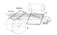
도 1은 전체 너비에 걸쳐 드레싱되지 않은 웜에 대해 수직인 방향의 벡터들을 가지는 웜 스레드(worm thread)의 프랭크(flank)의 부분을 개략적으로 도시한다. 벡터들의 수는 시뮬레이션 계산에 비해 여기서는 상당히 축소되었다. 여기서 개략적으로 도시되는 평면(4)은 벡터들이 배치되어 있는 전체적으로 곡선인 비 수정 웜의 프랭크에 대응한다. 벡터들(1 및 1')은 접촉 라인이 이미 넘어가 있으므로 전적으로 단축되어 있다. 벡터들(2 및 2')은 이미 적어도 한번 단축되었지만, 아직 접촉 라인이 넘어가 있지 않았다. 벡터들(3 및 3')은 아직 단축되지 않았고 그러므로 여전히 선택된 허용차(allowance)에 대응하는 길이를 가진다.
도 2는 예로서 여기서 기술되는 방법으로 워크피스 상에 선형의 팁 릴리프(tip relief)를 만드는 데 필요한 인벌루트 웜(involute worm) 상에서의 위상 표면 수정(topological surface modification)을 도시한다. 22는 접촉 경로를 표시하고; 25 내지 27은 드레서 및 웜 사이의 상이한 접촉 라인들을 표시한다.
도 3은 도 2와 동일하지만, 22에 대하여 약간 오프셋(offset)되어 연삭 중에 상이한 시프트(shift) 위치에 대응하는 추가 접촉 경로(23)가 있는 위상 표면 수정을 도시한다.
도 4는 예로서 여기서 기술되는 방법으로 워크피스 상에 선형의 팁 릴리프를 만드는 데 필요한 비 인벌루트 웜(non-involute worm) 상에서의 위상 표면 수정을 도시한다. 32는 접촉 경로를 표시하고; 35 내지 37은 드레서 및 웜 사이의 상이한 접촉 라인들을 표시한다.
도 5는 공통 랙(common rack) 및 2개의 기어링(gearing)들의 맞물림 평면(engagement plane)들을 포함하는 연속 창성 기어열(gear train)에서의 양 기어링들에 대한 표현을 도시한다. 더 양호한 실례를 위하여, 2개의 기어링들의 상대 위치는 연속 창성 기어열에서의 상대 위치에 대응하지 않는다. 본 도면은 또한 창성 랙(generating rack)에 대한 원통형 기어링의 상태 위치를 도시한다(출처는 1983년 베를린, Niemann, G; Winter, H: Maschinenelemente Band 3 2. Auflage, [Machine Elements Vol. 3, 2nd Edition] Springer Verlag).
도 6은 자신들을 창성하는 랙을 가지는 원추형 기어링에 대한 표현을 도시한다. 랙은 나선각(helix angle) ![]()
![]()
도 7은 횡절면(transverse section)에서의 우 프랭크의 창성 비대칭 랙과의 맞물림을 도시한다. 횡절면에서의 프로파일 각(![]()
![]()
![]()
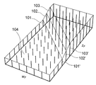
도 8은 전체 너비에 걸쳐 연삭되지 않은 워크피스에 대해 수직인 방향의 벡터들을 가지는 워크피스 치(tooth)의 플랭크의 부분을 개략적으로 도시한다. 벡터들의 수는 시뮬레이션 계산에 비해 여기서는 상당히 축소되었다. 여기서 개략적으로 도시되는 평면(104)은 벡터들이 배치되어 있는 전체적으로 곡선인 비 수정 워크피스의 프랭크에 대응한다. 벡터들(101 및 101')은 접촉 경로가 이미 넘어 지나갔으므로 전적으로 단축되어 있다. 벡터들(102 및 102')은 이미 적어도 한번 단축되었지만, 아직 접촉 경로가 넘어 지나가지 않았다. 벡터들(103 및 103')은 아직 단축되지 않았고 그러므로 여전히 선택된 허용차에 대응하는 길이를 가진다.
도 9는 여기에서 예들로서 기재되는 이동 장치를 가지는 기어 제작 기계를 개략적으로 도시한다.The present invention will now be described in more detail with reference to the drawings and embodiments. The figures show only the w-z diagrams of the cylindrical gearings as an example only. The w - z diagrams of conical gears are typically not trapezoidal, typically trapezoidal because the evaluation region of the creation path varies over the gearing width.
Figure 1 schematically shows a portion of the flank of a worm thread having vectors in a direction perpendicular to the unwound worm over its entire width. The number of vectors is considerably reduced here compared to the simulation calculation. The
Figure 2 shows a topological surface modification on an involute worm necessary to make a linear tip relief on a workpiece in the manner described herein by way of example. 22 denotes a contact path; 25 to 27 indicate different contact lines between the dresser and the worm.
Fig. 3 shows a phase surface modification, similar to Fig. 2, but with a slight offset relative to 22, with an
Figure 4 shows a phase surface modification on a non-involute worm required to make a linear tip relief on a workpiece in the manner described herein by way of example. 32 denotes a contact path; 35 to 37 indicate different contact lines between the dresser and the worm.
Figure 5 shows a representation of both gearings in a continuous gear train including a common rack and engagement planes of two gearings. For a better example, the relative positions of the two gear rings do not correspond to their relative positions in the continuous rise gear train. This figure also shows the state position of the cylindrical gearing with respect to the generating rack (source is 1983 Berlin, Niemann, G; Winter, H .:
Figure 6 shows a representation for a conical gearing with a rack that creates them. The rack has a helix angle, ![]()
![]()
Fig. 7 shows the engagement of the right flanks of the asymmetrical rack in the transverse section. The profile angle at the transverse plane ( ![]()
![]()
![]()
Figure 8 schematically shows a portion of a flank of a workpiece tooth having vectors in a direction perpendicular to a workpiece that is not ground across the entire width. The number of vectors is considerably reduced here compared to the simulation calculation. The
Figure 9 schematically illustrates a gear manufacturing machine having a moving device as described herein by way of example.
본 발명은 웜들을 드레싱하고 대응하여 드레싱된 웜을 가지는 평 기어(spur gear) 기어링을 창성 연삭하는 방법을 기술한다. 상기 방법에 의하여 윤곽 드레서(contour dresser)들의 시간 소모적인 사용 없이 소정의 드레서에 대한 특정한 제한들 내에서 창성 연삭(generating grinding)되는 기어링의 프로파일 형상이 자유로이 특정(specify)되는 것이 가능하다. 크라우닝(crowing)들 또는 루트(root)/팁(tip) 릴리프들과 같은 자유로운 프로파일 수정들은 특히 이 수정들을 저장하지 않거나 또는 다른 수정들을 저장하는 드레서에 의해서 구현될 수 있다. 기어링들은 모두 창성될 수 있는 프로파일들, 즉 웜에 의해 연삭될 수 있는 프로파일들을 가질 수 있다. 기어링들은 특히 인벌루트 프로파일들을 가질 수 있다. 기어링들은 대칭 및 비대칭 모두일 수 있다. 인벌루트 프로파일들의 경우, 이것은 프로파일 각들 및/또는 좌 및 우 프랭크들의 프로파일 수정이 또한 상이할 수 있음을 의미한다. 더욱이, 웜 및 기계 가공되는 워크피스 모두는 원통형이거나 원추형일 수 있다. 원추형 웜들 또는 워크피스들은 좌 및 우 플랭크들 상에서의 상이한 리드(lead)들을 특징으로 한다. 원통형인 경우에, 리드들은 양 측들에서 동일하다. 인벌루트, 원추형 기어링들은 흔히 또한 베벨로이드(beveloid)로 칭해진다.The present invention describes a method for grinding spur gearing with dressing worms and correspondingly dressed worms. With this method it is possible for the profile shape of the gearing to be generated grinding within certain limits for a given dresser to be freely specified without the time consuming use of contour dressers. Free profile modifications, such as crowings or root / tip reliefs, may be implemented by a dresser that does not specifically store these modifications or that stores other modifications. The gearings can all have profiles that can be created, that is, profiles that can be ground by the worm. The gearings may have particularly involute profiles. The gearings can be both symmetric and asymmetric. For involute profiles, this means that the profile angles of the profile angles and / or the profile modifications of the left and right flanks may also be different. Moreover, both the worm and the workpiece being machined can be cylindrical or conical. Conical worms or workpieces feature different leads on the left and right flanks. In the case of a cylindrical shape, the leads are the same on both sides. Involute, conical gearings are often also referred to as beveloids.
연삭 공정은 웜에 의해 발생하고, 상기 웜은 툴 길이에 걸쳐 위상이 수정되고 이의 축 방향은 웜 상의 접촉 경로가 기계 가공 동안 이동되지 않도록 연삭 공정 동안 워크피스의 축방향 이송(axial feed) 위치에 따라 시프트된다. 원통형 워크피스들이 연삭되면, 이 조건은 웜이 축 방향(축방향 창성 연삭)으로 시프트되지 않는 것과 등가이다. 원추형 워크피스들이 연삭되면, 상기 방법은 일반적으로 대각 창성 방법으로 발생한다. 접촉 경로가 웜 상에서 연장되는 곳은 여기서 상기 방법에 대해 결정적인 중요성을 가진다. 원통형 워크피스들이 연삭되는 경우, 어떤 시프트 위치(웜의 축방향 위치)에서 연삭이 발생하는지가 그러므로 중대하다. 원추형 워크피스가 연삭되는 경우, 대각비 및 연삭이 발생하는 시프트 범위, 즉 행정이 연삭 중에 어느 시프트 위치에서 시작되는지가 중대하다.The grinding process is caused by the worm and the worm is corrected in phase over the tool length and its axial direction is shifted to the axial feed position of the workpiece during the grinding process so that the worm- . When the cylindrical work pieces are ground, this condition is equivalent to the worm not being shifted in the axial direction (axial direction grinding). When the conical workpieces are ground, the method generally occurs in a diagonal creasing method. Where the contact path extends on the worm is of crucial importance to the method here. When cylindrical workpieces are to be ground, it is therefore important that the grinding takes place at a certain shift position (axial position of the worm). When the conical workpiece is ground, the diagonal ratio and the shift range at which the grinding occurs, i.e., at which shift position, the stroke is started during grinding, is great.
좌 및 우 플랭크들에 대해 상이하거나 상이할 수 있는 파라미터들에는 인덱스 F가 제공된다. F는 l(좌) 또는 r(우)일 수 있다. 인덱스 F가 나타나는 식들은 항상 좌 및 우 플랭크들에 적용된다.Parameters that may be different or different for the left and right flanks are provided with the index F. [ F may be l (left) or r (right). The expressions in which the index F appears are always applied to the left and right planks.
먼저 다음에 더 상세하게 논의될 인벌루트 기어링들은 기본 원 반경들(![]()
![]()
![]()
![]()
1. 원통형 대칭: rb := rbr = rbl 및 βb:=βbr=βbl 1. Cylindrical symmetry: r b : = r br = r bl and β b : = β br = β bl
2. 원통형 비대칭: rbr ≠ rbl 및 ![]()
![]()
3. 원추형 대칭: βbr ≠ βbl 및 rbrcosβbr = rblcosβbl 3. Conic symmetry: β br ≠ β bl And r br cos 硫br = r bl cos 硫bl
4. 원추형 비대칭: βbr ≠ βbl 및 rbrcosβbr ≠ rblcosβbl 및 ![]()
![]()
툴과 관련되는 값들에는 인텍스 1이 제공되고 워크피스와 관련되는 값들은 인덱스 2가 제공된다.Values associated with the tool are provided with
기어링 상의 프로파일 수정들은 함수 ![]()
![]()
![]()
![]()
![]()
![]()
인벌루트의 경우에 여기에서 기술되는 방법으로 웜 상에 제작 또는 사용되는 위상 면 수정(topological surface modification)들의 클래스가 다음에 규정된다. 위상 수정들은 일반적으로 함수 ![]()
![]()
![]()
![]()
![]()
![]()
![]()
![]()
인 함수 ![]()
![]()
실례로 말하자면, 이것은 면 수정이 치 플랭크(tooth flank) 상에서 모든 ![]()
![]()
![]()
![]()
![]()
![]()
이고, ![]()
![]()
![]()
![]()
![]()
![]()
![]()
![]()
본 발명의 기저의 개념은 다음에 더 상세하게 고찰될 것이다. 마찬가지로 인벌루트 기어링들을 가지는 웜은 큰 나선각을 가지는 경우에 하나의 규칙으로서 인벌루트 기어링들의 창성 연삭에 사용된다. 기계 가공 공정 동안에 이론적으로는 웜 및 기어링의 종단 기하 구조 사이에 점 접촉이 발생된다. 워크피스 및 치의 모두의 치 플랭크들의 면들은 전형적으로 롤링 경로(rolling path)(![]()
![]()
![]()
![]()

(3) (3)
ηbF: 또한 출원 DE 10 2012 015 846 A1을 참조할 것η bF : See also application DE 10 2012 015 846 A1.
sF는 좌 및 우 플랭크들에 대한 식들을 컴팩트한 형태로 기록하는 역할을 하고:s F serves to record the formulas for the left and right flanks in a compact form:

에 의해 규정된다.Lt; / RTI >
이 파라미터화는 툴 상에서 그리고 워크피스 상에서의 접촉점(접촉 경로)의 진행(progression)에 대하여 단순한 관계들이 계산되는 것을 가능하게 한다. 이 진행은 워크피스 상에서 워크피스의 축방향 이송에 의해 계속해서 변위된다. 이 진행들을 인지하면 워크피스 상의 지점을 툴 상의 지점과 분명하게 연관시키고 그리고 그 역으로 연관시키는 것이 가능해진다. 툴 상의 면 수정은 희망하는 수정이 워크피스 상에 제작되도록 이 연관에 의해 조정될 수 있다.This parameterization enables simple relationships to be calculated on the tool and on the progression of the contact points on the workpiece. This progression is continuously displaced by axial transfer of the workpiece on the workpiece. Recognizing these progresses makes it possible to correlate the points on the workpiece with the points on the tool and vice versa. The face modification on the tool can be adjusted by this association so that the desired modification is made on the workpiece.
관계들을 수학적으로 공식화하기 위하여 다음의 정의들이 행해진다:In order to formulate the relations mathematically, the following definitions are made:
다음의 항들은 변환을 위하여 사용된다:The following terms are used for conversion:
- ![]()
![]()
![]()
![]()
- Tx(v) x 방향으로 경로 v에 의한 평행 이동. y 및 z에 대해 유사- T x (v) translation by path v in the x direction. Similar to y and z
- H(A1,...,AN) 총 N개의 좌표들(A1 내지 AN)을 가지는 동질의 매트릭스(matrix)에 의해 기술 가능한 일반 변환. - H (A 1, ..., A N) N-number of coordinates (A 1 to A N) technology available general converted by a matrix (matrix) having a homogeneous.
용어 "좌표들"은 여기에서는 일반화된, 그러나 반드시 독립적인 것이 아닌 좌표에 대해 사용된다.The term "coordinates" is used herein for coordinates that are generalized but not necessarily independent.
휴지 중인 자체의 시스템에서의 기어링의 회전축은 항상 z 축과 일치한다. 기어링 중심은 z = 0에 있다.The axis of rotation of the gearing in its own system, which is idle, always coincides with the z-axis. The gearing center is at z = 0.
게다가 관계들의 공식이 워크피스 및 툴 사이의 상대 위치들을 기술하는 키네마틱 연쇄(kinematic chain)들을 규정하는 것이 중요하다. 이것은 툴 또는 워크피스가 원통형인지 또는 원추형인지에 좌우된다. 여기서는 모든 4개의 가능한 결합들이 고찰될 것이다.In addition, it is important to define the kinematic chains that describe the relative positions of the relationships between the workpiece and the tools. This depends on whether the tool or workpiece is cylindrical or conical. All four possible combinations will be considered here.
원통형 툴 및 원통형 Cylindrical tools and cylinders 워크피스에On the workpiece 대한 About 키네마틱Kinematic 연쇄 chain
툴 및 워크피스 사이의 상대 위치는 다음의 키네마틱 연쇄 KR에 의해 기술된다:The relative position between the tool and the workpiece is described by the following kinematic chain K R :
![]()
![]()
- ![]()
![]()
- ![]()
![]()
- zV1 : 툴의 축방향 이송(또한 시프트 위치로 칭해짐).- z V1 : Axial movement of tool (also referred to as shift position).
- zV2: 워크피스의 축방향 이송- z V2 : axial feed of the workpiece
- d: 중심 거리(툴/워크피스)- d: Center distance (tool / workpiece)
- γ: 축방향 교차각(툴/워크피스)- γ: Axial crossing angle (tool / workpiece)
원추형 툴 및 원통형 Conical tool and cylindrical 워크피스에On the workpiece 대한 About 키네마틱Kinematic 연쇄 chain
툴 및 워크피스 사이의 상대 위치는 다음의 키네마틱 연쇄 KR에 의해 기술된다:The relative position between the tool and the workpiece is described by the following kinematic chain K R :
![]()
![]()
- ![]()
![]()
- ![]()
![]()
- zV1 : 툴의 이송(또한 시프트 위치로 칭해짐).- z V1 : tool feed (also referred to as shift position).
- zV2: 워크피스의 축방향 이송- z V2 : axial feed of the workpiece
- d: 중심 거리에 대한 치수(툴/워크피스)- d: Dimension for center distance (tool / workpiece)
- γ: 축방향 교차각(툴/워크피스)- γ: Axial crossing angle (tool / workpiece)
- ![]()
![]()
- ![]()
![]()
원통형 툴 및 원추형 Cylindrical tools and cones 워크피스에On the workpiece 대한 About 키네마틱Kinematic 연쇄 chain
툴 및 워크피스 사이의 상대 위치는 다음의 키네마틱 연쇄 KR에 의해 기술된다:The relative position between the tool and the workpiece is described by the following kinematic chain K R :
![]()
![]()
- ![]()
![]()
- ![]()
![]()
- zV1 : 툴의 축방향 이송(또한 시프트 위치로 칭해짐).- z V1 : Axial movement of tool (also referred to as shift position).
- zV2: 워크피스의 이송- z V2 : Feed of workpiece
- d: 중심 거리에 대한 치수(툴/워크피스)- d: Dimension for center distance (tool / workpiece)
- γ: 축방향 교차각(툴/워크피스)- γ: Axial crossing angle (tool / workpiece)
- ![]()
![]()
- ![]()
![]()
원추형 툴 및 원추형 Conical tools and cones 워크피스에On the workpiece 대한 About 키네마틱Kinematic 연쇄 chain
툴 및 워크피스 사이의 상대 위치는 다음의 키네마틱 연쇄 KR에 의해 기술된다:The relative position between the tool and the workpiece is described by the following kinematic chain K R :

- ![]()
![]()
- ![]()
![]()
- zV1 : 툴의 이송(또한 시프트 위치로 칭해짐).- z V1 : tool feed (also referred to as shift position).
- zV2: 워크피스의 이송- z V2 : Feed of workpiece
- d: 중심 거리에 대한 치수(툴/워크피스)- d: Dimension for center distance (tool / workpiece)
- γ: 축방향 교차각(툴/워크피스)- γ: Axial crossing angle (tool / workpiece)
- ![]()
![]()
- ![]()
![]()
- ![]()
![]()
- ![]()
![]()
이 키네마틱 연쇄들은 처음에는 다만 여기에서 기술되는 본 발명의 수학적 기술만을 제공한다. 이것들은 본 발명이 사용되는 기계의 물리적 축들과 정합하지 않아도 된다. 기계가 변환식These kinematic chains initially provide only the mathematical description of the present invention described herein. They do not have to match the physical axes of the machine in which the present invention is used. The machine converts
![]()
![]()
에 따라 툴 및 워크피스 사이의 상대 위치들을 가능하게 하는 이동 장치를 가지면, 본 발명은 방금 기술된 키네마틱 연쇄들로부터의 좌표들의 세트별로(이 세트는 본 발명에서 계산된다) 좌표들(![]()
![]()
![]()
![]()
이다.to be.
좌표들(![]()
![]()
모든 필요한 상대 위치들을 가능하게 하는 전형적인 이동 장치는 예를 들어, 다음의 키네마틱 연쇄들에 의해 기술된다:A typical mobile device that enables all necessary relative positions is described by, for example, the following kinematic chains:
![]()
![]()
![]()
![]()
도 9는 ![]()
![]()
기어 제조 기계는 제조 기계 및 드레싱 기계의 결합이다. 기어 제조 기계는 툴 홀더(tool holder)를 가지는 좌측에 도시되는 기계 가공 헤드, 중앙에 도시되는 워크피스 홀더 및 우측에 개략적으로 도시되는 드레서 홀더를 가진다. 워크피스 홀더에 고정되는 워크피스는 기어 제조 기계 가공을 수행하기 위하여 툴 홀더에 고정되는 툴에 의해 기계 가공될 수 있다. 드레싱 공정을 수행하기 위해, 툴 홀더에 고정되는 툴은 드레서 홀더에 고정되는 드레서에 의해 기계 가공될 수 있다. 이것은 드레싱을 위한 툴이 툴 홀더 내에서 유지될 수 있는 장점을 가진다. 기계 가공 헤드(head)의 이동축들은 더욱이 드레서 상에 트레서 및 툴의 상대 위치를 설정하는 데 사용될 수 있다.The gear manufacturing machine is a combination of a manufacturing machine and a dressing machine. The gear manufacturing machine has a machining head shown on the left with a tool holder, a workpiece holder shown at the center and a dresser holder shown schematically on the right. The workpiece secured to the workpiece holder may be machined by a tool secured to the toolholder to perform gearmaking machining. To perform the dressing process, the tool fixed to the tool holder can be machined by a dresser fixed to the dresser holder. This has the advantage that the tool for dressing can be retained in the tool holder. The movement axes of the machining head can furthermore be used to set the relative positions of the tool and the tracer on the dresser.
기어 제조 기계는 툴 홀더를 이동시키기 위하여 A1, B1, V1, X1 및 Z1, 워크피스 홀더를 이동시키기 위해 C2, 그리고 드레서를 이동시키기 위해 B3, C5의 이동축들을 가진다.The gear manufacturing machine has movement axes A1, B1, V1, X1 and Z1 to move the tool holder, C2 to move the workpiece holder, and B3, C5 to move the dresser.
상세하게, B1은 툴의 자체의 회전축을 중심으로 툴의 회전을 가능하게 하고; X1은 툴 또는 워크피스의 회전 축에 수직인 툴의 병진 이동을 가능하게 하고; Z1은 수직 방향이거나 워크피스의 회전축과 평행한 툴의 병진 이동을 가능하게 하고; A1은 툴의 피봇 이동을 가능하게 하고; V1은 자체의 회전 축의 방향으로의 툴의 시프트 이동 또는 접선방향 이동을 가능하게 하고; C2는 워크피스의 회전 이동을 가능하게 하고; B3는 자체의 회전 축을 중심으로 드레싱 툴의 회전 이동을 가능하게 하고; 그리고 C5는 드레싱 툴의 피봇 이동이 툴에서 압력각(α)을 변경시키는 것을 가능하게 한다.In detail, B1 makes it possible to rotate the tool about its own axis of rotation; X1 enables translation of the tool perpendicular to the axis of rotation of the tool or workpiece; Z1 permits translational movement of the tool in a vertical direction or parallel to the axis of rotation of the workpiece; A1 enables pivotal movement of the tool; V1 enables shift or tangential movement of the tool in the direction of its own axis of rotation; C2 enables rotational movement of the workpiece; B3 enables rotational movement of the dressing tool about its own axis of rotation; And C5 enables the pivoting movement of the dressing tool to change the pressure angle [alpha] in the tool.
본 발명에 따른 방법들을 수행하기 위해 다른 기어 제조 기계들 및/또는 드레싱 기계들이 또한 사용될 수 있다. zV2 좌표는 기계 가공 공정 동안 이동되고 그러므로 워크피스의 이송이 구현된다. 원통형 휠들에 있어서, 이것은 축방향 이송이고; 원추형 휠들에 있어서, 이 이송은 축방향은 아니지만 기어링의 축에 대해 원추 각(![]()
![]()
그러나, 추가 과정에서, 용어 이송은 또한 원통형 툴들 또는 워크피스들의 경우 ![]()
![]()
![]()
![]()
원통형 및/또는 원추형 툴들 및 워크피스들의 4개의 가능한 결합들이 별개로 고찰될 것이다. 각각의 경우에서의 시작 지점은 창성 연삭 시 툴 상에서의 그리고 워크피스 상에서의 접촉점의 진행을, 이송 위치들(![]()
![]()
![]()
![]()
이에 대한 준비로, 이 목적에 필요한 웜들 상의 수정들 및 드레싱에 의한 이것들의 제작이 먼저 논의될 것이다.In preparation for this, modifications to the worms required for this purpose and the production of these by dressing will be discussed first.
툴들, 여기서에 고찰될 대칭 또는 비대칭인 원통형 및 원추형 웜들은 마찬가지로 식 (1)에 따른 수정을 가진다. 이 수정의 유형은 특히 드레싱 가능 연삭 웜들에 있어서 매우 유용한데 왜냐하면 이것은 드레싱 휠로 드레싱할 때 웜 상에 용이하게 제작될 수 있기 때문이다. 드레싱 휠로 드레싱할 때, 드레싱 휠 및 웜의 플랭크들 사이에는 라인 접촉이 있다. 이 접촉 라인이 양 플랭크들에 대해 ![]()
![]()
![]()
![]()
![]()
![]()
에 의해 주어지는, 매우 양호한 근사치로 직선이 획득된다.A straight line is obtained with a very good approximation.
![]()
![]()
![]()
![]()
![]()
![]()
웜 및 드레서 사이의 상대 위치는 다음의 키네마틱 연쇄 KBR에 의해 기술된다:The relative position between the worm and the dresser is described by the following kinematic chain K BR :
![]()
![]()
- ![]()
![]()
- ![]()
![]()
- ![]()
![]()
- ![]()
![]()
- d: 중심 거리- d: center distance
- ![]()
![]()
이 키네마틱 연쇄는 처음에는 먼저 여기서 기술되는 본 발명의 수학적 기술을 제공한다. 이것은 본 발명이 사용되는 기계의 물리적 축들과 정합하지 않아도 된다. 기계가 변환식This kinematic chain first provides a mathematical description of the present invention as described herein. This does not necessarily correspond to the physical axes of the machine in which the present invention is used. The machine converts
![]()
![]()
![]()
![]()
에 따라 웜 및 드레서 사이의 상대 위치들을 가능하게 하는 이동 장치를 가지면, 본 발명은 방금 설명된 키네마틱 연쇄들로부터의 좌표들의 세트별로(세트는 본 발명에서 계산된다) 좌표들(![]()
![]()
H(![]()
![]()
이다.to be.
좌표들(![]()
![]()
모든 필요한 상대 위치들을 가능하게 하는 전형적인 이동 장치는 예를 들어, 다음의 키네마틱 연쇄들에 의해 기술된다:A typical mobile device that enables all necessary relative positions is described by, for example, the following kinematic chains:
![]()
![]()
![]()
![]()
도 9는 ![]()
![]()
![]()
![]()
· 중심 거리 및/또는Center distance and / or
· 웜의 축방향 위치 및/또는The axial position of the worm and / or
· 드레서의 y 위치 및/또는The y position of the dresser and / or
· 웜의 회전 각 및/또는Rotation angle of the worm and / or
· 웜 축 및 드레서 축 사이의 축방향 교차각· Axial crossing angle between the worm axis and the dresser axis
은 현재의 접촉 라인을 따라 일정한 수정이 제작되도록 정정될 수 있다.May be corrected to produce a constant correction along the current contact line.
웜이 비수정 상태에서 드레싱되면, 웜의 축방향 위치만이 웜의 피치 높이를 통해 결합되고, 웜의 회전각은 드레싱 공정 동안 변경된다. 이에 의해 접촉 라인은 나선 라인에 따른 웜 길이를 따라 이동되고 플랭크의 특정 영역까지 넘어 지나가며 이를 드레싱한다. XF1는 그러므로 웜의 축방향 위치의 함수이다.When the worm is dressed in a non-modified state, only the axial position of the worm is coupled through the pitch height of the worm, and the rotational angle of the worm is changed during the dressing process. Whereby the contact line is moved along the worm length along the spiral line and overshoots to a certain area of the flank and dresses it. X F1 is therefore a function of the axial position of the worm.
![]()
![]()
이 관계는 단일 플랭크 드레싱 및 2-플랭크 드레싱 모두에 적용된다.This relationship applies to both single-faced dressing and two-flange dressing.
드레싱이 2개의 플랭크들 상에서 수행되면, 상대 위치의 정정들은 임의의 희망하는 일정한 수정들(ftl1 및 ftr1)이 특정한 한도들 내에서 서로에 독립적으로 웜의 양 플랭크들 상에서 현재의 접촉 라인들을 따라 좌에 그리고 우에 적용될 수 있도록 선택될 수 있다. 특정한 한도들 내에서 자유로운, 좌 및 우 플랭크들 상에서의 수정들의 선택은 상술한 상대 위치의 정정들이 모두 좌 및 우 플랭크들에서 동일하게 작용하지 않는다는 사실에 기인한다. 축방향 간격의 변화는 예를 들어, 결과적으로 좌 및 우 플랭크들 상에서의 수정이 동일한 부호로 발생하고; 대칭 원통형 웜의 경우에 또한 동일한 양으로 발생한다. 반대로, 웜의 회전 각의 변화는 결과적으로 좌 및 우 플랭크들 상에서의 수정이 상이한 부호들로 발생하고; 대칭 원통형 웜의 경우에 동일한 양으로 발생한다. 웜의 회전각 및 축방향 간격은 그러므로 예를 들어, 희망하는 수정들(ftl1 및 ftr1)이 현재의 접촉 라인을 따라 달성되도록 세팅될 수 있다. 이것은 일반적으로 다음과 같이 기술될 수 있다: 드레싱 공정 중에 이용할 수 있고, 좌표들(![]()
![]()
![]()
![]()
![]()
![]()
![]()
![]()
웜이 비수정된 상태로 드레싱되면, 웜의 축방향 위치(zS)만이 상술한 바와 같이 변경된다. 이 위치는 그러므로 이 경우에 대하여 zS의 함수:When the worm is dressed in a non-modified state, only the axial position z s of the worm is changed as described above. This position is therefore a function of z S for this case:
![]()
![]()
![]()
![]()
인 좌표들(![]()
![]()
이는 여기에서 기술되는 수정들을 가지는 웜의 드레싱 중에 좌표들(![]()
![]()
, 여기서 ![]()
![]()
좌표들의 정정들(![]()
![]()
![]()
![]()
![]()
![]()
웜들은 여기에서 기술되는 방법을 위해 필요하고 이는 식 (1)에서 기술되는 바와 같은 수정을 가지며, 방향(![]()
![]()
![]()
![]()
![]()
![]()
![]()
![]()
![]()
![]()
![]()
![]()
![]()
![]()
![]()
![]()
수정들(![]()
![]()
![]()
![]()
![]()
![]()
접촉 라인의 위치들(![]()
![]()
![]()
![]()
2-플랭크 드레싱에 대하여 여기서 제시되는 방법은 단일-플랭크 드레싱에 직접적으로 전해질 수 있다. 이 경우에, 좌 및 우 플랭크들에 대한 식들은 완전히 분리되고 계산은 각 플랭크 별로 별개로 수행될 수 있다.The method presented here for 2-flank dressing can be conducted directly to the single-flank dressing. In this case, the expressions for the left and right planes are completely separate and the computation can be performed separately for each flank.
식 (13)에 따라 필요한 축 정정들(![]()
![]()
![]()
![]()
![]()
![]()
![]()
![]()
![]()
![]()
![]()
![]()
![]()
![]()
이후에 필요한 모든 정보를 전달할 수 있는 가능한 알고리즘이 여기서 상세하게 제시될 것이다. 이 목적을 위해, 일반적으로 수정되지 않은 웜이 먼저 고찰된다. 이전에 고정된 길이를 가지는 수직 방향의 벡터들이 이 웜의 스레드들 상에 좌표들(![]()
![]()
![]()
![]()
![]()
![]()
![]()
![]()
![]()
![]()
![]()
![]()
![]()
![]()
![]()
![]()
![]()
![]()
![]()
![]()
![]()
![]()
길이의 약간의 차들은 여기에서 기술되는 알고리즘이 시간의 이산화(discretization)로 인하여 이송 마킹(feed marking)들을 발생시킨다는 사실로부터 기인한다. 이 이송 마킹들 및 따라서 또한 웜의 소정의 반경 상에서의 벡터들의 길이들의 차들은 시간 단계들의 단축과 등가인 더 미세한 시간의 이산화에 의해 감소될 수 있다. 시뮬레이션이 웜의 총 너비에 걸쳐 수행되지 않고, 오히려 웜의 소정의 축방향 시프트 위치(![]()
![]()
![]()
![]()
![]()
![]()
![]()
![]()
![]()
![]()
![]()
![]()
![]()
![]()
![]()
![]()
![]()
![]()
![]()
![]()
인벌루트 웜들의 경우, 접촉 라인은 좌표들(![]()
![]()
![]()
![]()
여기서 ![]()
![]()
![]()
![]()
![]()
![]()
![]()
![]()
접촉 라인이 연장되는 벡터들이 결정되면, 이를 위해 이전에 저장된 드레서 상의 반경들(![]()
![]()
![]()
![]()
![]()
![]()
![]()
![]()
![]()
![]()
접촉 라인 및 반경의 연관이 이 방식으로 결정될 수 있는 정확도는 지점들의 선택된 거리 그리고 또한 이산의 시간 단계들의 길이 모두에 좌우된다. 양 값들은 이론적으로는 원하는 만큼 작게 선택될 수 있으나, 실제적으로 이 값들은 이용 가능한 RAM 및 최대 허용 가능 계산 시간에 의해 제한된다. 이 계산은 실제로 멀티플 기가바이트 RAM 및 초고속 다중 코어 시스템들을 구비한 현재 이용 가능한 PC들을 사용하여 충분한 정확도로 가능하다.The accuracy with which the association of contact lines and radii can be determined in this way depends on both the selected distance of points and also the length of the discrete time steps. The positive values may be selected theoretically as small as desired, but practically these values are limited by the available RAM and the maximum allowable calculation time. This calculation is actually possible with sufficient accuracy using currently available PCs with multiple gigabytes of RAM and ultra-fast multicore systems.
웜 스레드 면 상에서 수직 방향으로 규정되는, 웜 상의 지점에서의 수정(![]()
![]()
![]()
![]()
![]()
![]()
![]()
![]()
![]()
![]()
식 (19)에 기술되는 바와 같이, ![]()
![]()
![]()
![]()
![]()
![]()
![]()
![]()
![]()
![]()
원통형 툴 및 원통형 워크피스Cylindrical tool and cylindrical workpiece
다음에는 식 (1)에 따른 수정을 가지는 웜의 도움으로, 원통형 툴 및 원통형 워크피스의 경우에 대하여 축방향 창성 연삭 시에 순 프로파일 수정이 어떻게 제작될 수 있는지가 도시된다. 이 목적을 위해, 워크피스 및 웜 사이의 접촉점의 진행 은 축 이송들(![]()
![]()
![]()
![]()
![]()
![]()
![]()
![]()
![]()
![]()
![]()
![]()
![]()
![]()
여기에서 도입된 계수들(![]()
![]()
![]()
![]()
![]()
![]()
![]()
![]()
![]()
![]()
![]()
![]()
![]()
![]()
![]()
![]()
이 관계는 웜 및 워크피스 모두의 경우 ![]()
![]()
![]()
![]()
![]()
![]()
고정된 창성 경로(![]()
![]()
![]()
![]()
![]()
![]()
로 제공된다..
여기에서 도입되는 계수들(![]()
![]()
![]()
![]()
![]()
![]()
![]()
![]()
![]()
![]()
![]()
![]()
방금 제시된 관계들은 식 (4)로부터의 키네마틱 연쇄에 따라 서로에 대하여 지향되는 2개의 인벌루트 기어링들의 접촉 지점들의 분석 계산으로부터 직접적으로 도출된다.The relationships just presented are derived directly from the analysis calculations of the points of contact of the two involute gearings oriented with respect to each other according to the kinematic chain from Eq. (4).
이제 웜 상의 지점을 워크피스 상의 모든 지점과 연관시키기 위하여 상기 관계들을 활용하는 것이 본 발명의 기본 개념이다. 여기에서는 웜이 식 (1)에 따라 특정한 한도들 내에서 임의의 바람직한 수정을 가지고 프로파일 수정이 워크피스 상에서 제작되어야 하는 사실이 활용된다.It is now a fundamental concept of the present invention to utilize these relationships to associate points on the worm with all points on the workpiece. Here, the worm exploits the fact that the profile modification must be made on the workpiece with any desired modifications within certain limits according to equation (1).
이를 위해, 워크피스 상의 창성 경로(![]()
![]()
![]()
![]()
![]()
![]()
![]()
![]()
![]()
![]()
![]()
![]()
![]()
![]()
![]()
![]()
![]()
![]()
![]()
![]()
![]()
![]()
![]()
![]()
소정의 ![]()
![]()
![]()
![]()
이는 웜 상의 접촉 경로가 행정 중에 시프트되지 않는다는 사실과 동등하다.This is equivalent to the fact that the contact path on the worm is not shifted during the stroke.
이 이론은 이제 전이 영역 없는 선형 팁 릴리프의 예를 위해 도 2의 도움으로 실례의 방식으로 보일 것이다. 이 도는 ![]()
![]()
![]()
![]()
![]()
![]()
![]()
![]()
![]()
![]()
![]()
![]()
원추형 툴 및 원통형 워크피스Conical tool and cylindrical workpiece
창성 연삭은 지금까지 단지 원통형 웜들에 의한 것만이 공지되어 있다. 그러나, 또한 원추형 웜들을 툴로서 사용하는 것이 가능하다. 이 공정의 키네마틱스는 원추형 및 원통형 휠을 가지는 연속 창성 기어열에 의해 기술될 수 있다. 이 키네마틱스들은 식 (5)에서 제공되는 키네마틱 연쇄에 의해 기술된다. 2개의 원통형 휠들을 포함하는 연속 창성 기어열에서와 같이, 양 휠들 사이에서는 또한 이론적인 점 접촉이 있다. 이것으로 인해 원통형 툴들의 경우에서와 동일한 방법이 사용되는 것이 가능한, 즉, 식 (1)에 따른 수정을 가지는 웜은 대각 창성 방법에서 마찬가지로 워크피스 상에 식 (1)에 따라 수정을 제작하기 위하여 사용된다. 워크피스 및 웜 사이의 접촉점의 진행은 다음과 같이 수학적으로 기술될 수 있다.In grinding grinding, only cylindrical worms have been known so far. However, it is also possible to use conical worms as tools. The kinematics of this process can be described by a continuous rudimentary gear train with conical and cylindrical wheels. These kinematics are described by the kinematic chain provided in Eq. (5). There is also a theoretical point contact between both wheels, as in a continuous dynamoing gear train comprising two cylindrical wheels. This makes it possible to use the same method as in the case of cylindrical tools, that is, worms with modifications according to equation (1) can be used in the diagonal creasing method to produce crystals according to equation (1) Is used. The progress of the contact point between the workpiece and the worm can be described mathematically as follows.
![]()
![]()
![]()
![]()
여기에서 도입되는 계수들(![]()
![]()
![]()
![]()
![]()
![]()
![]()
![]()
![]()
![]()
![]()
![]()
![]()
![]()
![]()
![]()
![]()
![]()
![]()
![]()
![]()
![]()
![]()
![]()
식 (34)는:Equation (34) is:
![]()
![]()
에 의해 대체된다.Lt; / RTI >
여기에서 도입되는 계수들(![]()
![]()
![]()
![]()
![]()
![]()
![]()
![]()
![]()
![]()
![]()
![]()
![]()
![]()
이 관계들에 대한 정보로, 원통형 툴들 및 워크피스들의 경우와 유사한 방식으로 웜 상의 지점들의 워크피스 상의 지점들로의 매핑이 계산될 수 있다. 식 (1)에 따른 웜 상의 수정이 다시 여기에서 취해지면 ![]()
![]()
![]()
![]()
![]()
![]()
![]()
![]()
원통형 툴 및 원추형 Cylindrical tools and cones 워크피스Workpiece
여기에서 기술되는 방법은 원추형 워크피스들의 창성 연삭으로 이전될 수 있고, 여기서 연삭은 일반적으로 대각 창성 방법에 의해 실행되어야만 한다. 식 (1)에 따른 수정을 가지는 원통형 웜의 경우가 여기에서 먼저 고찰된다. 웜 및 워크피스는 다시 키네마틱스가 식 (6)에 의해 제공되는 연속 창성 기어열을 형성한다. 다시 웜 및 워크피스 사이에는 이론적인 점접촉이 또한 존재한다. 워크피스 및 웜 사이의 접촉점의 진행은 수학적으로 다음과 같이 기술될 수 있다:The method described herein can be transferred to the creased grinding of conical workpieces, where the grinding generally has to be carried out by a diagonal creasing method. The case of a cylindrical worm with modification according to equation (1) is considered here first. The worm and the workpiece again form a continuous crew gear train in which the kinematics is provided by Eq. (6). Again there is theoretical point contact between the worm and the workpiece. The progress of the contact point between the workpiece and the worm can be mathematically described as:
![]()
![]()
![]()
![]()
여기에서 도입되는 계수들(![]()
![]()
![]()
![]()
![]()
![]()
![]()
![]()
![]()
![]()
![]()
![]()
![]()
![]()
![]()
![]()
![]()
![]()
![]()
![]()
![]()
![]()
![]()
![]()
식 (34)는:Equation (34) is:
![]()
![]()
에 의해 대체된다.Lt; / RTI >
여기에서 도입되는 계수들(![]()
![]()
![]()
![]()
![]()
![]()
![]()
![]()
![]()
![]()
![]()
![]()
![]()
![]()
원추형 워크피스들의 경우에, 식 (53)은 ![]()
![]()
![]()
![]()
![]()
![]()
![]()
![]()
![]()
![]()
![]()
![]()
![]()
![]()
![]()
![]()
![]()
![]()
![]()
![]()
![]()
![]()
![]()
![]()
![]()
![]()
![]()
![]()
![]()
![]()
![]()
![]()
식 (66)에 따른 ![]()
![]()
![]()
![]()
![]()
![]()
![]()
![]()
![]()
![]()
![]()
![]()
![]()
![]()
![]()
![]()
![]()
![]()
![]()
![]()
![]()
![]()
원추형 워크피스의 2-플랭크 연삭은 원추형 툴을 사용함으로써 가능해진다.Two-flange grinding of the conical workpiece is made possible by using a conical tool.
원추형 툴 및 원추형 Conical tools and cones 워크피스Workpiece
원추형 툴 및 원추형 워크피스에 대한 계산은 이전에 논의된 결합들과 유사하게 발생한다. 웜 및 워크피스는 식 (7)에 의해 제공되는 키네마틱스를 지니는 연속 창성 기어열을 다시 형성한다. 다시 웜 및 워크피스 사이의 이론적인 점 접촉이 또한 존재한다. 워크피스 및 웜 사이의 접촉점의 진행은 수학적으로 다음과 같이 기술될 수 있다.The calculations for the conical tool and the conical workpiece occur similar to the combinations discussed previously. The worm and the workpiece re-form the continuous creeping gear train with the kinematics provided by equation (7). Again there is theoretical point contact between the worm and the workpiece. The progress of the contact point between the workpiece and the worm can be mathematically described as follows.
![]()
![]()
![]()
![]()
여기에서 도입되는 계수들(![]()
![]()
![]()
![]()
![]()
![]()
![]()
![]()
![]()
![]()
![]()
![]()
![]()
![]()
![]()
![]()
![]()
![]()
![]()
![]()
![]()
![]()
![]()
![]()
![]()
![]()
![]()
![]()
![]()
![]()
![]()
![]()
식 (34)는:Equation (34) is:
![]()
![]()
으로 대체된다..
여기에서 도입되는 계수들(![]()
![]()
![]()
![]()
![]()
![]()
![]()
![]()
![]()
![]()
![]()
![]()
![]()
![]()
![]()
![]()
![]()
![]()
![]()
![]()
식 (67)은 또한 시프트되지 않는 접촉 경로가 단지 대각 창성 연삭에 의해서 다시 달성될 수 있도록 원추형 툴들의 경우에서의 ![]()
![]()
![]()
![]()
![]()
![]()
![]()
![]()
![]()
![]()
![]()
![]()
![]()
![]()
여기에서 일반적으로 좌 및 우 플랭크들에 대한 계산된 대각비는 단일 플랭크 연삭만이 가능하도록 상이하다. 그러나, 대각비가 양 측들에 대해 동일하도록 웜의, 특히 원추각(![]()
![]()
![]()
![]()
![]()
![]()
![]()
![]()
여기에서 편위 대각비에 의한 대각 창성 연삭으로의 전이는 또한 DE 10 2015 000 907에 마찬가지로 기술되어 있는 추가 가능성을 제공한다.Here, the transition to diagonal grinding by the diagonal diagonal ratio also provides the additional possibility described in DE 10 2015 000 907 as well.
툴 상의 그리고 Tools and 워크피스Workpiece 상의 접촉 경로들을 계산하는 계산 방법 A calculation method for calculating contact paths on a wafer
다음에는, 이송들에 따라 위에서 사용되는 접촉 경로들이 계산될 수 있는 계산 방법을 보일 것이다. 워크피스 및 툴 사이의 접촉에 대한 이 계산은 하나하나 각각 워크피스 및 툴에 대한 랙(rack)인, 2개의 이론적인 랙들(또한 기초 랙들로 칭해짐)의 도움으로 수행되고, 각각은 기어링들을 발생시킬 수 있는 사다리꼴, 일반적으로 비대칭인 프로파일들을 가진다. 툴 및 워크피스 모두가 인벌루트 기어링들이므로, 이 관찰은 툴 및 워크피스의 전환점에 대하여 대칭이다.Next, we will show the calculation method by which the contact paths used above can be calculated according to the movements. This calculation for the contact between the workpiece and the tool is carried out with the aid of two theoretical racks (also referred to as basic racks), one each for the workpiece and the tool rack, Trapezoidal, generally asymmetric profiles that can be generated. Since both the tool and the workpiece are involute gearings, this observation is symmetrical about the turning point of the tool and the workpiece.
도 7은 횡절면에서 우 인벌루트 플랭크가 프로파일 각(![]()
![]()
![]()
![]()
![]()
![]()
![]()
![]()
![]()
![]()
![]()
![]()
![]()
![]()
![]()
![]()
![]()
![]()
![]()
![]()
![]()
![]()
![]()
![]()
![]()
![]()
![]()
![]()
![]()
![]()
랙 대 기어링의 상대 위치 및 기하구조가 공지되면, 임의의 희망하는 너비 위치들에 대해 횡절면들이 결정되고 이들 내에서 랙 및 플랭크 사이의 접촉점이 결정될 수 있다. 개별 횡절면들에서의 모든 이 접촉점들은 회전각(![]()
![]()
![]()
![]()
![]()
![]()
![]()
![]()
![]()
![]()
![]()
![]()
![]()
![]()
![]()
![]()
![]()
![]()
![]()
![]()
![]()
![]()
기어링들의 2 세트들이 연속 창성 기어열에서 쌍을 이루고 있으면, 이들의 2개의 랙들은 도 5에 도시되는 바와 같이, 항상 합치되어야 한다. 이것은 프로파일 각들(![]()
![]()
![]()
![]()
랙들이 항상 합치되도록, 결과적으로 두 이송들 및 두 회전각들 사이에는 선형 제약(R4)이 있다.As a result, there is a linear constraint R4 between the two traverses and the two rotation angles so that the racks are always aligned.
두 이송들 및 두 회전각들이 공지되면, 두 기어 치들의 세트의 접촉점은 두 직선의 접촉 라인들의 교차점을 계산함으로써 직접적으로 결정될 수 있다. 기어(1) 또는 기어링(2) 상의 접촉점을 기술하는 파라미터들(![]()
![]()
![]()
![]()
![]()
![]()
![]()
![]()
![]()
![]()
![]()
![]()
![]()
![]()
![]()
![]()
선형 관계(R7)는 ![]()
![]()
![]()
![]()
![]()
![]()
![]()
![]()
![]()
![]()
![]()
![]()
툴 및 워크피스가 서로 맞물리도록 다음이 적용되어야 한다:In order for the tool and the workpiece to mesh with each other, the following shall apply:
![]()
![]()
방금 기술된 방법 또는 인벌루트 기어링들에 대한 대안으로, 시뮬레이션 계산의 도움으로 피치각들 사이의 관계(R7) 및 접촉 경로들(R6)을 수행하는 것이 또한 가능하다. 그와 같은 시뮬레이션들에 의해 소정의 툴로부터, 특히 웜으로부터 그리고 소정의 키네마틱스로부터, 특히 툴 및 워크피스 사이의 소정의 상대 위치로부터 워크피스의 정확한 기하구조를 계산하는 것이 가능하다. 그와 같은 시뮬레이션들은 이 시뮬레이션들에 의해 워크피스의 그리고 툴의 이송에 따라 툴 상의 어떤 지점이 워크피스 상의 어떤 지점을 제작하는지를 결정하는 것이 또한 가능하도록 확장될 수 있다. 이 경로에서, 이 경로가 비 인벌루트 프로파일들에 대하여 또한 사용될 수 있도록 인벌루트 프로파일들이 사용되지 않는다. 이에 적합한 알고리즘이 다음에 설명될 것이다.As an alternative to the method just described or involute gearing, it is also possible to perform the relationship R7 and the contact paths R6 between the pitch angles with the aid of simulation calculations. With such simulations it is possible to calculate the exact geometry of the workpiece from a given tool, in particular from a worm and from certain kinematics, in particular from a given relative position between the tool and the workpiece. Such simulations can be extended by these simulations to make it possible to determine which points on the tool produce the workpiece and which points on the workpiece, depending on the transfer of the tool. In this path, involute profiles are not used so that this path can also be used for non-involuntary profiles. An algorithm suitable for this will be described next.
이 목적을 위해, 대개 수정되지 않은 워크피스가 먼저 검토된다. 이전에 고정된 길이를 가지는 수직 방향으로의 벡터들은 이 워크피스의 치들 상에 좌표들(![]()
![]()
![]()
![]()
![]()
![]()
![]()
![]()
![]()
![]()
길이들에서의 약간의 차들은 여기에서 기술되는 알고리즘이 시간의 이산화(discretization)로 인하여, 창성 동안의 창성 컷들과 유사하게, 마킹들을 발생시킨다는 사실로부터 기인한다. 이 마킹들, 그리고 따라서 워크피스의 소정의 반경에서의 벡터들의 길이들의 차는 시간 단계들의 축소와 등가인 시간의 더 미세한 이산화에 의해 감소될 수 있다. 시뮬레이션이 워크피스의 총 너비에 걸쳐 수행되지 않고, 오히려 워크피스의 소정의 축방향 시프트 위치(![]()
![]()
![]()
![]()
![]()
![]()
![]()
![]()
![]()
![]()
![]()
![]()
인벌루트 경우에 웜이 원추형이고 워크피스가 원통형이면, 적어도 2개의 상이한 이송들(![]()
![]()
![]()
![]()
![]()
![]()
![]()
![]()
![]()
![]()
다른 수정들과의 중첩Overlap with other modifications
종래 기술로부터 공지되어 있는 수정들은 여기에서 기술된 방법을 사용하여 제작될 수 있는 순 프로파일 수정들에 대한 간섭없이 추가로 중첩될 수 있다. 한편, 이것들은 부가적으로 사용되는 드레서에 저장될 수 있는 순 프로파일 수정들이다. 그러므로 여기에서 기술된 방법을 사용하는 특정한 제약들 내에서, 프로파일 수정을 저장하는 드레서를 사용하여, 웜 상에 그리고 이에 따라 워크피스 상에 상이한 자유 프로파일 수정을 제작하는 것 또한 가능하다. 이 목적을 위해서, 희망하는 프로파일 수정으로부터의 그리고 드레서에 저장되어 있는 프로파일 수정으로부터의 차만이 여기에서 기술된 방법으로 제작되어야만 한다. 예를 들어, 한편, 프로파일 크라우닝들은 그러므로 변경 또는 제작될 수 있지만, 팁 릴리프들 및/또는 루트 릴리프들은 예를 들어 드레서가 이미 그것들을 저장하고 있는지 또는 그것들이 어떤 양 또는 어떤 길이를 가지는 것과는 관계없이 자유로이 생성될 수 있다.The modifications known from the prior art can be further superimposed without interference to the net profile modifications that may be made using the methods described herein. On the other hand, these are net profile modifications that can be stored in the dresser to be used additionally. Thus, within certain constraints using the method described herein, it is also possible to produce different free profile modifications on the worm and thus on the workpiece, using a dresser that stores profile modifications. For this purpose, only the differences from the desired profile modification and from the profile modification stored in the dresser must be produced in the manner described herein. For example, on the one hand, profile crowns can therefore be altered or fabricated, but tip reliefs and / or root reliefs can be used, for example, if the dresser already stores them or if they have any amount or any length Can be freely generated.
예를 들어, 드레서가 프로파일 크라우닝을 저장하면, 달성되는 프로파일 크라우닝이 드레서 상의 프로파일 크라우닝으로부터 벗어나도록 여기에서 기술된 방법으로 추가 프로파일 크라우닝이 제작될 수 있다.For example, if the dresser stores a profile crowning, additional profile crowning can be made in the manner described here so that the profile crowning achieved is free from profile crowning on the dresser.
기어링들 상에 수정들을 제작하는 종래 기술 DE10208531로부터 공지되는 추가 방법은 연삭 공정 동안 키네마틱스를 정정하는 것을 포함한다. 그와 같은 수정들은 예를 들어 축방향 간격을 변경함으로써 그리고/또는 회전각을 정정함으로써 그리고/또는 이송들을 정정함으로써 구현될 수 있다. 그와 같은 정정들은 항상 접촉 경로를 따라 영향을 미치고 이를 따라 동일한 값을 가진다. 이 방법에 의해 제작될 수 있는 수정들은 그러므로 식 (1)에 의해 또한 기술될 수 있다. 그러나, ![]()
![]()
![]()
![]()
![]()
![]()
이 점에 있어서, 함수들 ![]()
![]()
![]()
![]()
대각 창성 연삭과는 별개로 또는 연삭이 원통형 워크피스 상에서 수행되어야 하는 규정되는 시프트 위치와는 별개로, 본 출원의 기저인 본 발명에서는 연삭 키네마틱스의 정정이 필요하지 않으므로, 연삭 키네마틱스의 정정 및 이에 따른 식 (84)에 따른 수정은 간섭 없이 추가로 중첩될 수 있다.Independent of the diagonal creasing grinding or the defined shift position where the grinding should be performed on the cylindrical workpiece, the correction of the grinding kinematics is not necessary in the present invention, which is the basis of the present application, The corrections according to equation (84) can then be further superimposed without interference.
툴의Of the tool 분리 및 활용 Isolation and Utilization
여기에서 기술된 방법을 사용하여 워크피스를 연삭하기 위하여, 특정한 너비를 가지는 웜 상에는 영역이 필요하다. 이 너비는 일반적으로 축방향 창성 연삭에서와 같이, 플랭크마다, 웜의 너비 방향에서의 접촉 경로(22)의 범위에 대응한다. 상기 방법이 원추형 워크피스들에 적용되는 연삭은 인정컨대 대각이지만, 접촉 경로는 웜 상의 실제로 사용되는 영역의 너비가 축방향 창성 연삭에서의 너비와 대응하도록 시프트되지 않는다. 웜을 최적으로 활용하기 위해, 그와 같은 영역들이 웜 상에 복수개로 적용될 수 있다. 그러나, 이 영역들의 각각에서는 프로파일 수정이 정확하게 제작될 수 있는 단 하나의 접촉 경로가 존재하고, 이에 의해 웜의 면 중 적어도 일부만이 사용될 수 있다. 웜을 더 효율적으로 사용할 수 있기 위하여, 웜을 시프트함으로써 이상적인 접촉 경로에 대하여 미세하게 시프트되는 접촉 경로들을 활용하는 것 또한 가능하다. 원추형 워크피스들 및 이에 필요한 대각 창성 연삭의 경우에, 시프트하는 것은 고정 오프셋(![]()
![]()
접촉 라인에 따른 일정하지 않은 수정Uncorrected corrections along the contact line
접촉 경로가 이상적인 접촉 경로에 대하여 시프트될 때 희망하는 수정에 대해 발생하는 편위들을 줄이기 위하여, 드레서 및 웜 사이의 접촉 라인에 따른 수정이 일정하지 않는 경우가 장점이 될 수 있다. 웜의 드레싱 상에서 모든 이용 가능한 자유도들을 활용함으로써 w에서 적어도 대략 1차 또는 2차인 수정을 제작하는 것이 가능하다. 그러한 경우 웜 상의 위상 수정은 적어도 근사적으로:It may be advantageous if the correction along the contact line between the dresser and the worm is not constant in order to reduce the deviations occurring to the desired correction when the contact path is shifted relative to the ideal contact path. It is possible to make modifications that are at least approximately first or second order in w by utilizing all available degrees of freedom on the dressing of the worm. In such a case, the phase correction on the worm is at least approximate:
![]()
![]()
로서 기재될 수 있다.≪ / RTI >
희망하는 1차 또는 2차 수정을 달성하기 위해 ![]()
![]()
함수들(![]()
![]()
![]()
![]()
![]()
![]()
![]()
![]()
![]()
![]()
![]()
![]()
비 ratio 인벌루트Involute 기어링들에To gearing 있어서의 적용 Application
이전에 기술된 바와 같은 방법은 또한 비 인벌루트 기어링들 또는 프로파일들로 바로 확장될 수 있고, 여기서 기어링들은 또한 다시 비대칭이고/이거나 원추형일 수 있다. 이 점에 있어서, 인벌루트 기어링들에 대해 위해 표시된 선형 관계들은 일반적으로 선형이 아니다. 여기서 파라미터(![]()
![]()
![]()
![]()
![]()
![]()
![]()
![]()
![]()
![]()
![]()
![]()
이 식은 식 (25)의 일반화를 표현한다. 웜에 적용되는 수직 방향으로의 위상 수정은 식 (1)의 일반화를 통해 기술될 수 있다.This expression expresses the generalization of Eq. (25). The phase correction in the vertical direction applied to the worm can be described through generalization of Eq. (1).
![]()
![]()
![]()
![]()
![]()
![]()
![]()
![]()
![]()
![]()
![]()
![]()
![]()
![]()
![]()
![]()
![]()
![]()
인벌루트 경우와는 대조적으로, 수정들은 여기에서 수직의 절면으로 고려되었다. 관계들 및 접촉 경로 및 접촉 라인 모두는 더 이상 선형 관계들에 의해 기술될 수 없으므로, 연관들은 보통 수치적으로 계산되어야만 한다. 도 4는 3개의 상이한 ![]()
![]()
상이한 매크로 기하구조에 대한 For different macro geometries 드레서들Dresser
드레서는 항상 단지 하나의 웜 기하구조와만 수학적으로 정확하게 정합한다. 웜의 매크로 기하구조가 변하면, 특히, 스레드들의 수 및/또는 직격이 변하면, 드레서는 더 이상 정합되지 않고 드레싱 동안 원치 않는 프로파일 에러가 발생한다. 순 프로파일 각 에러가 종래 기술에 따라 드레서의 내향 피봇에 의해 정정되는 반면에, 다른 프로파일 에러들은 정정될 수 없다. 인벌루트 기어링들에서, 예를 들어, 드레서가 드레싱될 웜과 정확하게 정합하지 않을 때 그에 따라 그 중에서도 특히 프로파일 크라우닝들이 발생한다. 그와 같은 프로파일 에러들은 이전에 정정될 수 없고 비 정합 드레서들은 사용될 수 없다. 그러나, 이제 여기에서 제시되는 방법을 사용하여 비정합 드레서로 인해 발생하는 프로파일 에러를 정정하는 것이 가능하다. 희망하는 프로파일 수정 및 비정합 드레서에 의해 발생하는 프로파일 에러 사이의 차로부터 기인하는 프로파일 수정은 이 목적을 위해 상기 방법을 사용하여 제작된다. 이에 의해 이미 이용 가능한 드레서들을 더 빈번하게 이용하는 것이 가능하고 새로운 드레서들에 대한 투가 비용들 및 드레서의 전달까지의 대기 시간 모두가 없어도 된다.The dresser always mathematically matches exactly one worm geometry only. If the macro geometry of the worm changes, especially if the number and / or stiffness of the threads changes, then the dresser is no longer matched and an unwanted profile error occurs during dressing. While the net profile each error is corrected by the inward pivot of the dresser according to the prior art, other profile errors can not be corrected. In involute root gearing, for example, when the dresser is not correctly aligned with the worm to be dressed, profile creeping occurs accordingly, amongst others. Such profile errors can not be corrected previously, and unmatched dressers can not be used. However, it is now possible to correct the profile error caused by the unmatched dresser using the method presented here. The profile modification resulting from the difference between the desired profile modification and the profile error caused by the unmatched dresser is made using this method for this purpose. Thereby, it is possible to use the already available dressers more frequently, and it is not necessary to have both the transfer costs for the new dressers and the waiting time until the delivery of the dresser.
비정합 드레서 기하구조의 문제는 웜이 드레싱되도록 설계되지 않은 드레서가 사용되어야 할 때뿐만 아니라 웜 직경이 드레싱 사이클에 따라서 더 작아질 때에도 존재한다. 많은 경우들에서, 변하는 웜 직경에 의하여 발생하는 프로파일 에러들은 너무 작아더 이 에러들은 허용된 공차 내에 있게 된다. 그러나, 이는 웜 직경 대 연삭될 기어링의 모듈의 비가 너무 작아질 때 그리고/또는 스레드들의 수가 아주 많을 때 더 이상 유효하지 않다. 작은 직경들을 가지는 웜들은 예를 들어, 더 큰 웜에 의한 창성 연삭이 간섭 윤곽으로 인해 더 이상 가능하지 않을 때 사용될 수 있다. 추가 적용은 큰 모듈 기어링들의 연삭이다. 사용될 수 있는 웜 직경들이 상향으로 제한되므로, 웜 직경 대 모듈의 비는 모듈이 증가할수록 감소한다. 또한 높은 테이블 속도들을 구현하기 위한 현대의 기어 제조 기계들의 용량으로 인하여 더 큰 수들의 스타트(start)들을 가지는 웜들을 사용하는 것 또한 가능하다.The problem of unmatched dresser geometry exists not only when a dresser not designed to dress the worm is used, but also when the worm diameter becomes smaller along the dressing cycle. In many cases, profile errors caused by varying worm diameters are so small that these errors are within the allowed tolerances. However, this is no longer valid when the ratio of the worm diameter to the module of gearing to be ground is too small and / or the number of threads is very large. Worms with small diameters can be used, for example, when a larger worm-induced grinding is no longer possible due to interference contours. Additional application is grinding of large module gearings. Since the worm diameters that can be used are limited upwards, the ratio of worm diameter to module is reduced as the module is increased. It is also possible to use worms with a larger number of starts due to the capacity of modern gear making machines to implement high table speeds.
그와 같은 웜들이 사용되면, 새로운 상태로 웜에 대하여 구성되는 드레서는 드레싱이 종래의 방법에 따라 일어나면, 더 작은 반경의 경우에 원치 않은 프로파일 결함을, 인벌루트 웜들의 경우에 원치 않는 프로파일 크라우닝을 발생시킨다. 이 프로파일 에러 또는 이 프로팡리 크라우닝이 공차 밖에서 웜 직경 아래에 있으면, 웜은 소정의 드레서를 사용하여 더 드레싱될 수 없고, 이에 의해, 최대 유용한 층 두께는 제한된다. 이 문제는 이전에는 단지 상이한 직경 범위들에 대해 상이한 드레서들을 사용함으로써 해결되는 것이 가능하였다. 그러나, 여기에서 기술된 방법에 의해서, 프로파일 형상을 단 하나의 드레서에 의해 큰 직경 범위에 걸쳐 일정하게 유지하는 것이 가능하다. 드레서는 이 목적을 위해 웜과 정합하지 않는 드레서가 된다.If such worms are used, the dresser constructed for the worm in a new state will cause undesirable profile defects in the case of smaller radii, undesirable profile crowding in the case of involute worms, . If this profile error or this proximal crowning is below the worm diameter outside the tolerance, the worm can not be further dressed using a given dresser, thereby limiting the maximum useful layer thickness. This problem has previously been possible to be solved by using different dressers only for different diameter ranges. However, by the method described herein, it is possible to keep the profile shape constant over a large diameter range by only one dresser. The dresser becomes a dresser that does not match the worm for this purpose.
Claims (23)
상기 워크피스와의 접촉 경로는 상기 기계 가공 행정 동안 상기 툴 상에서 시프트(shift)되지 않는 것을 특징으로 하는 방법.CLAIMS What is claimed is: 1. A method of making a workpiece having a modified gearing geometry by a generating method, the workpiece being machined by a tool having a modified gearing geometry, Wherein said tool has a phase correction, said method comprising the steps of:
Wherein the contact path with the workpiece is not shifted on the tool during the machining stroke.
원통형 워크피스가 기계 가공되고 상기 기계 가공은 축방향(axial) 창성 방법에 의해 이루어지는 방법.The method according to claim 1,
Wherein the cylindrical workpiece is machined and the machining is performed by an axial creasing method.
원추형 워크피스가 기계 가공되고 상기 기계 가공은 대각(diagonal) 창성 방법에 의해 이루어지고, 대각비(diagonal ratio)는 상기 툴 상의 접촉 경로가 상기 기계 가공 행정 동안 시프트되지 않도록 선택되고; 바람직하게는 원통형 기초 형태를 가지는 툴이 사용되고 상기 기계 가공은 하나의 플랭크 상에서 이루어지거나; 또는 바람직하게는 원추형 기초 형상을 가지는 툴이 사용되고 상기 기계 가공은 2개의 플랭크들 상에서 이루어지고; 상기 툴의 원추각 및 상기 대각비는 더 바람직하게는 상기 접촉 경로가 2-플랭크(two-flank) 기계 가공 동안 우 및 좌 플랭크들 상에서 시프트되지 않도록 선택되는 방법.The method according to claim 1,
Wherein the conical workpiece is machined and the machining is by a diagonal creasing method and a diagonal ratio is selected such that the contact path on the tool is not shifted during the machining stroke; A tool having a cylindrical base shape is preferably used and the machining is done on one flank; Or preferably a tool having a conical basic shape is used and the machining is done on two flanks; Wherein the cone angle and the diagonal ratio of the tool are more preferably selected such that the contact path is not shifted on the right and left flanks during two-flank machining.
상기 툴의 면 기하구조의 위상 수정은 창성 패턴(pattern)에서 적어도 국지적으로 상기 툴의 제 1 방향으로 상수 값을 가지고 상기 제 1 방향에 수직으로 연장되는 상기 툴의 제 2 방향으로 함수(FFt1)에 의해 제공되고;
그리고/또는 상기 창성 패턴에서의 상기 툴의 제 1 방향으로의 상기 툴의 상기 면 기하구조의 상기 위상 수정은 적어도
툴 너비 방향에서의 계수들이 상수 부분에 대해 FFtC,1, 1차 부분에 대해 FFtL,1, 그리고/또는 2차 부분에 대해 FFtQ,1인 계수 함수들이 제공되는 상수, 1차 또는 2차 함수로서 근사적으로 나타내어질 수 있고;
상기 제 1 방향은 바람직하게는 드레싱 동안의 드레서의 동작 라인의 방향에 대응하는 방법.4. The method according to any one of claims 1 to 3,
Phase modification of the surface geometry of the tool in the second direction of the tool and extending perpendicular to the first direction, at least locally, have a constant value in the first direction of the tool in Changsung pattern (pattern) function (F Ft1 );
And / or the phase modification of the surface geometry of the tool in a first direction of the tool in the creation pattern is at least
Coefficients in the tool width direction are F FtC for the constant part, F FtL for the 1 st, 1 , and / or constants for which the F FtQ, 1 coefficient functions are provided for the quadratic part, Can be approximated as a difference function;
Wherein the first direction preferably corresponds to the direction of the operating line of the dresser during dressing.
상기 워크피스의 희망하는 프로파일 수정은 특정되고 상기 워크피스 상에서 상기 창성 기계 가공에 의해서 제작되고; 상기 희망하는 프로파일 수정 및/또는 상기 희망하는 수정의 속성들은 바람직하게는 특정 조건들 내에서 자유로이 특정 가능하고; 그리고/또는 상기 프로파일 수정의 다음의 속성들:
- 크라우닝(crowning);
- 프로파일 각 편위(angle deviation);
- 팁 릴리프(tip relief);
- 루트 릴리프(root relief);
중 하나, 바람직하게는 상기 속성들 중 복수의 속성들, 그리고 더 바람직하게는 상기 속성들 중 모두는 특정 가능하고;
바람직하게는 다음의 데이터:
- 상기 크라우닝의 크기;
- 상기 프로파일 각 편위의 크기;
- 상기 팁 릴리프의 양 및 위치;
- 상기 루트 릴리프의 양 및 위치
가 특정될 수 있고,
더 바람직하게는, 상기 속성들 중 적어도 하나에 대해 그리고/또는 상기 속성들의 데이터에 대하여 입력 박스(input box)들을 가지는 적어도 하나의 입력 마스크(input mask)가 제공되고;
그리고/또는 상기 희망하는 프로파일 수정은 연속 수정(continuous modification)으로서 그리고/또는 복수의 롤링 각(rolling angle)들로 자유로이 특정 가능한 방법.5. The method according to any one of claims 1 to 4,
The desired profile modification of the workpiece is specified and made on said workpiece by said incising machining; The attributes of the desired profile modification and / or the desired modification are preferably freely definable within certain conditions; And / or the following properties of the profile modification:
- crowning;
- profile angle deviation;
- tip relief;
- root relief;
One of the attributes, preferably all of the attributes, and more preferably all of the attributes are identifiable;
Preferably the following data:
The size of the crowning;
The magnitude of said profile angular deviation;
The amount and position of the tip relief;
The amount and location of the root relief
Can be specified,
More preferably, at least one input mask is provided having input boxes for at least one of the attributes and / or for data of the attributes;
And / or the desired profile modification is freely determinable as a continuous modification and / or with a plurality of rolling angles.
상기 툴의 상기 위상 수정은 상기 드레싱 동안 상기 툴에 대한 상기 드레서의 위치가 상기 툴의 회전각에 따라 그리고/또는 상기 툴 너비 위치에 따라 변동됨으로써 제작되는 방법.6. The method according to any one of claims 1 to 5,
Wherein the phase modification of the tool is fabricated by varying the position of the dresser relative to the tool during the dressing according to the rotational angle of the tool and / or the tool width position.
상기 창성 방법은 상기 툴 상에서 규정된 접촉 경로로 실행되고; 상기 위상 수정 및/또는 상기 접촉 경로는 상기 접촉 경로를 따른 상기 툴 상에서의 상기 위상 수정이 상기 워크피스 상에 희망하는 프로파일 수정을 제작하는 형상을 가지도록 선택되고; 상기 위상 수정은 바람직하게는 상기 접촉 경로에 따라 선택되거나 또는 상기 접촉 경로는 바람직하게는 상기 접촉 경로를 따른 상기 툴 상의 상기 위상 수정이 상기 워크피스 상에 희망하는 프로파일 수정을 제작하는 형상을 가지도록 상기 위상 수정에 따라 선택되고; 그리고/또는 규정된 접촉 경로에 있어서의 상기 기계 가공은 바람직하게는 상기 툴의 규정된 초기 시프트 위치에 있어서의 기계 가공을 포함하고; 원통형 워크피스의 기계 가공 중에, 상기 초기 시프트 위치는 더 바람직하게는 유지되고 그리고/또는 원추형 워크피스의 기계 가공 중에 상기 툴은 상기 초기 시프트 위치에서부터 시작하여, 상기 접촉 경로가 시프트되지 않는 그러한 대각비만큼 시프트되는 방법.7. The method according to any one of claims 1 to 6,
The creation method is performed with a contact path defined on the tool; Wherein the phase correction and / or the contact path is selected such that the phase modification on the tool along the contact path has a shape to produce a desired profile modification on the workpiece; The phase correction is preferably selected according to the contact path or the contact path is preferably such that the phase correction on the tool along the contact path has a shape to produce the desired profile modification on the workpiece Selected according to the phase modification; And / or said machining in a defined contact path preferably comprises machining at a defined initial shift position of said tool; During machining of the cylindrical workpiece, the initial shift position is more preferably maintained and / or during the machining of the conical workpiece, the tool is started from the initial shift position, such diagonal ratio Lt; / RTI >
- 상기 워크피스 상에 희망하는 프로파일 수정을 특정하는 단계;
- 상기 워크피스 상에 상기 희망하는 프로파일 수정을 제작하는 데 필요한 규정된 접촉 경로를 따라 상기 툴의 수정을 결정하는 단계;
- 상기 접촉 경로를 따라 이 방식으로 결정되는 상기 수정에 대응하는 상기 툴의 위상 수정을 결정하고; 그리고/또는 상기 접촉 경로를 따라 이 방식으로 결정되는 상기 수정에 대응하는 위상 수정을 제공하는 데 적합하게 상기 툴의 드레싱 동안 상기 툴에 대한 상기 드레서의 위치의 변동을 결정하는 단계를 포함하고,
상기 위상 수정은 바람직하게는 드레싱 동안 상기 툴에서부터의 상기 드레서의 위치가 상기 툴의 상기 회전각에 따라 그리고/또는 상기 툴 너비 위치에 따라 변동됨으로써 제작되고; 그리고 상기 변동은 바람직하게는 각각 상기 툴의 특정한 회전각 및/또는 툴 너비 위치로 제공되는 상기 드레서의 상기 툴과의 동작 라인 및 상기 툴의 상기 워크피스와의 상기 접촉 경로 사이의 교차 지점에서 특정한 수정이 일어나도록 발생하거나 또는 결정되고; 그리고
상기 규정된 접촉 경로는 바람직하게는 규정된 초기 시프트 위치에 의해서 특정되는 방법.8. The method according to any one of claims 1 to 7,
- specifying the desired profile modification on the workpiece;
- determining a modification of the tool along a prescribed contact path necessary to produce the desired profile modification on the workpiece;
Determine a phase correction of the tool corresponding to the modification determined in this way along the contact path; And / or determining a variation in the position of the dresser relative to the tool during dressing of the tool, the dressing being adapted to provide a phase correction corresponding to the modification determined in this manner along the contact path,
The phase modification is preferably made by varying the position of the dresser from the tool during dressing according to the rotation angle of the tool and / or the tool width position; And said variations are preferably determined at intersection points between the working line of the dresser with the tool and the contact path with the workpiece of the tool, each of which is provided at a specific rotation angle and / or tool width position of the tool, respectively Occurs or is determined such that a correction occurs; And
Wherein said defined contact path is preferably specified by a defined initial shift position.
상기 워크피스 상에 상기 희망하는 수정을 제작하는 데 적합한 접촉 경로를 따른 상기 툴의 상기 수정을 결정하기 위해, 각각의 접촉 경로들을 형성하는 상기 툴 및 상기 워크피스 사이의 접촉 지점들의 결정이 상기 창성 기계 가공 중에 먼저 발생하고; 그리고/또는
위상 수정을 제공하는 데 적합한 상기 툴에 대한 상기 드레서의 상기 위치의 변동을 결정하기 위해, 상기 드레서의 상기 툴로의 동작 라인은 상기 툴의 회전각에 따라 그리고/또는 상기 툴 너비 위치에 따라 결정되고; 상기 동작 라인의 방향은 바람직하게는 특히 인벌루트 기어링들에 대하여 일정한 것으로 취해지거나; 또는 상기 동작 라인의 방향에 대한 수정의 영향은 특히 비 인벌루트 기어링들에 대하여 고려되는 방법.9. The method of claim 8,
Wherein the determination of the contact points between the tool and the workpiece forming respective contact paths is performed to determine the modification of the tool along a contact path suitable for fabricating the desired crystal on the workpiece, Occurs first during machining; And / or
The operating line to the tool of the dresser is determined according to the rotation angle of the tool and / or the tool width position to determine a variation of the position of the dresser relative to the tool that is suitable for providing a phase correction ; The direction of the operating line is preferably taken as constant, especially for involute gearings; Or the effect of the correction on the direction of the operating line is taken into account, in particular for non-involute root gearings.
기계 가공 키네마틱스(kinematics)는 상기 툴의 상기 위상 수정에 의해 제작되는 상기 워크피스 상의 수정 상에 상기 기계 가공 키네마틱스의 수정에 의해 제작되는 수정을 중첩(superpose)하기 위하여 상기 창성 방법의 프레임워크(framework) 내에서 수정되는 방법.10. The method according to any one of claims 1 to 9,
Mechanical machining kinematics is performed by superposing a modification made on the machining kinematics on a modification on the workpiece produced by the phase modification of the tool, the framework is modified within the framework.
상기 툴을 드레싱하기 위하여 수정 드레서가 사용되고; 그리고 상기 드레서의 상기 수정에 의해 제작되는 상기 툴의 상기 수정은 자체에 중첩되고 상기 드레서의 상기 툴에 대한 위치가 드레싱 동안 상기 툴의 상기 회전각에 따라 그리고/또는 상기 툴 너비 위치에 따라 변동됨으로써 제작되는 위상 수정을 가지고; 상기 위상 변동은 바람직하게는 상기 워크피스와의 선택된 접촉 경로를 따른 상기 툴 상의 수정들의 중첩이 상기 워크피스 상에 희망하는 프로파일 수정을 제작하는 데 필요한 상기 접촉 경로를 따른 수정에 대응하도록 선택되는 방법.11. The method according to any one of claims 1 to 10,
A correction dresser is used to dress the tool; And wherein the modification of the tool produced by the modification of the dresser is superimposed on itself and the position of the dresser relative to the tool is varied according to the rotation angle of the tool during dressing and / Having a phase correction made; The phase variation is preferably selected such that the superposition of the modifications on the tool along the selected contact path with the workpiece is selected to correspond to a modification along the contact path required to produce the desired profile modification on the workpiece .
상이한 매크로 기하구조(macrogeometry)를 가지는 툴, 특히 상이한 직경 및/또는 상이한 수의 스레드(thread)들을 가지는 툴을 위해 설계된, 상기 툴을 드레싱하기 위한 드레서가 사용되고; 비 정합 드레서에 의해 제작되는 상기 워크피스와의 선택된 접촉 경로에서의 상기 툴의 면 기하구조의 수정은 드레싱 동안 상기 드레서의 상기 툴에 대한 위치가 상기 툴의 상기 회전각에 따라 그리고/또는 상기 툴 너비 위치에 따라 적절하게 변동되므로 보상되고; 그리고 상기 창성 기계 가공 방법은 바람직하게는 상기 선택된 접촉 경로를 사용하여 수행되는 방법.12. The method according to any one of claims 1 to 11,
A dresser for dressing the tool is designed which is designed for a tool having a different macrogeometry, especially for a tool having different diameters and / or different numbers of threads; Correction of the surface geometry of the tool in the selected contact path with the workpiece made by the unmatched dresser is achieved by adjusting the position of the dresser relative to the tool during dressing according to the rotation angle of the tool and / It is compensated because it varies appropriately according to the width position; And the inventive machining method is preferably performed using the selected contact path.
적절하게 드레싱된 툴에 의해 희망하는 기어링 기하구조를 가지는 워크피스를 제조하기 위하여,
- 상기 워크피스의 희망하는 프로파일 수정을 특정하는 단계;
- 드레싱 공정의 수정 없이 드레서 및 툴의 복수의 결합들로부터, 상기 희망하는 프로파일 수정에서부터 가장 작은 편위들을 발생시키는 결합을 선택하는 단계;
상기 편위들을 보상하기 위한 상기 툴의 위상 수정을 제작하기 위하여 라인 접촉되어 있는 상기 드레서에 의해 상기 툴을 수정 드레싱하는 단계; 및
상기 희망하는 프로파일 수정을 제작하기 위해 상기 기계 가공 행정에 걸쳐 변경되지 않은 접촉 경로를 가지는 상기 드레싱된 툴에 의해 상기 워크피스를 기계 가공하는 단계를 포함하고,
상기 드레서들 및/또는 툴들은 바람직하게는 적어도 부분적으로 특정되거나 이미 존재하는 범위인 방법.13. The method according to any one of claims 1 to 12,
To produce a workpiece having the desired gearing geometry by a suitably dressed tool,
- specifying the desired profile modification of the workpiece;
Selecting a combination from a plurality of combinations of the dresser and tool without modifying the dressing process to produce the smallest deviations from the desired profile modification;
Modifying the tool by the dresser in line contact to produce a phase correction of the tool to compensate for the deviations; And
Machining the workpiece by the dressed tool having an unaltered contact path throughout the machining stroke to produce the desired profile modification,
Wherein the dressers and / or tools are preferably at least partially specified or pre-existing ranges.
적절하게 드레싱된 툴에 의해 희망하는 기어 기하구조를 가지는 하나 이상의 워크피스들을 제조하기 위하여, 하나 이상의 기계 가공 단계들을 수행한 후에, 상기 툴은 동일한 워크피스에서 또는 추가 워크피스들에서 추가 기계 가공 단계들이 수행되기 전에 각각 드레싱되고,
이후의 드레싱 공정에서, 상기 툴의 상이한 위상 수정은 이전의 드레싱 공정에 대하여 제작되는 것을 특징으로 하는 방법.14. The method according to any one of claims 1 to 13,
After one or more machining steps have been carried out, in order to manufacture one or more workpieces with the desired gear geometry by suitably dressed tools, the tool may be machined at the same workpiece or at additional machining steps Are each dressed before being performed,
In a subsequent dressing process, different phase modifications of the tool are made for a previous dressing process.
하나 이상의 워크피스들의 기계 가공 동안, 적어도 하나의 행정은 상기 툴의 제 1 초기 시프트 위치로 그리고/또는 제 1 접촉 경로로 수행되고 적어도 하나의 제 2 행정은 상기 툴의 시프트된 제 2 초기 시프트 위치로 그리고/또는 시프트된 제 2 접촉 경로로 수행되고,
상기 제 1 초기 시프트 위치 및/또는 상기 제 1 접촉 경로는 바람직하게는 상기 제 2 초기 시프트 위치 및/또는 상기 제 2 접촉 경로보다는 이상적인 초기 시프트 위치 및/또는 이상적인 접촉 경로에 대하여 더 적게 시프트되고; 상기 제 1 초기 시프트 위치는 바람직하게는 상기 이상적인 시프트 위치에 대응하고 그리고/또는 상기 제 1 접촉 경로는 상기 이상적인 접촉 경로에 대응하고;
그리고/또는 거친 기계 가공(rough machining) 단계는 바람직하게는 상기 제 2 초기 시프트 위치로 그리고/또는 상기 제 2 접촉 라인으로 수행되고 미세 기계 가공(fine machining) 단계는 상기 제 1 초기 시프트 위치로 그리고/또는 상기 제 1 접촉 라인으로 수행되는 방법.15. The method according to any one of claims 1 to 14,
During machining of the one or more workpieces, at least one stroke is performed to a first initial shift position of the tool and / or to a first contact path and at least one second stroke is performed to a shifted second initial shift position And / or with a shifted second contact path,
The first initial shift position and / or the first contact path are preferably shifted less for an ideal initial shift position and / or an ideal contact path than the second initial shift position and / or the second contact path; The first initial shift position preferably corresponds to the ideal shift position and / or the first contact path corresponds to the ideal contact path;
And / or a rough machining step is preferably performed to the second initial shift position and / or to the second contact line and a fine machining step is performed to the first initial shift position and / / ≪ / RTI > or the first contact line.
상기 툴의 상기 수정은 창성 패턴에서 적어도 국지적으로 상기 툴의 제 1 방향으로 1차 및/또는 2차 함수에 의해 상기 적어도 근사적으로 기술될 수 있고; 상기 1차 및/또는 2차 함수들의 계수들은 상수 부분에 대해 FFtC,1, 1차 부분에 대해 FFtL,1, 그리고/또는 2차 부분에 대해 FFtQ,1인 계수 함수들에 의해 상기 제 1 방향에 수직으로 연장되는 상기 툴의 제 2 방향으로 형성되고;
상기 상수 부분에 대한 상기 계수 함수(FFtC,1)는 희망하는 프로파일 수정이 상기 창성 기계 가공 시에 특정된 시프트 위치에서 그리고/또는 특정된 접촉 경로를 따라 정확하게 제작되도록 결정되고; 그리고 상기 1차 부분에 대한 상기 계수 함수(FFtL,1) 및/또는 상기 2차 부분에 대한 상기 계수 함수(FFtQ,1)는 창성 기계 가공 중에 적어도 하나의 시프트된 초기 시프트 위치 및/또는 접촉 경로 그리고/또는 초기 시프트 위치들 및/또는 접촉 경로들의 적어도 하나의 대역(band) 또는 범위(range)로 상기 워크피스에서 발생하는 상기 희망하는 프로파일 수정으로부터의 편위가 최소가 되도록 결정되고;
상기 결정은 바람직하게는 곡선 맞춤(curve fitting)에 의해 발생하고, 그리고/또는 상기 편위들은 바람직하게는 상기 프로파일에 따라 상이한 공차들을 고려하기 위하여 상기 창성 경로에 따라 상이하게 가중되고; 그리고/또는 상기 시프트된 초기 시프트 위치들 및/또는 접촉 경로들의 간격 또는 상기 대역의 폭은 바람직하게는 상기 워크피스 상에 발생하는 편위가 모든 접촉 경로들에서 미리 규정된 공차 내에 계속해서 있도록 반복해서 결정되는 방법.16. The method according to any one of claims 1 to 15,
The modification of the tool may be described at least approximately by a first order and / or a second order function in a first direction of the tool, at least locally in a creation pattern; The coefficients of the primary and / or quadratic functions are calculated by F FtC for a constant part, F FtL for a 1 st, 1 , and / or F FQ for a quadratic part, A second direction of the tool extending perpendicular to the first direction;
The coefficient function (F FtC, 1 ) for the constant part is determined such that the desired profile modification is made exactly at the shift position specified in the machining machining and / or along the specified contact path; And wherein said coefficient function for the primary part (F FtL, 1) and / or the coefficient function for the second part (F FtQ, 1) is at least one of the shifted initial shift position during Changsung machining and / or The deviation from the desired profile modification occurring in the workpiece to a contact path and / or at least one band or range of initial shift positions and / or contact paths is minimized;
The determination is preferably made by curve fitting, and / or the deviations are weighted differently according to the creation path, preferably to account for different tolerances according to the profile; And / or the spacing of the shifted initial shift positions and / or contact paths or the width of the band is preferably repeated so that the deviations occurring on the workpiece continue within a predefined tolerance in all contact paths How to be determined.
상기 툴은 제 1 위상 수정을 가지는 적어도 하나의 영역 및 제 2 위상 수정을 가지는 제 2 영역을 가지고, 제 1 초기 시프트 위치에서의 상기 워크피스와의 접촉 경로를 따른 상기 제 1 위상 수정은 제 2 초기 시프트 위치에서의 상기 워크피스와의 접촉 경로를 따른 상기 제 2 위상 수정과 동일하고;
적어도 하나의 행정은 하나 이상의 워크피스들의 기계 가공 중에 상기 툴의 상기 제 1 초기 시프트 위치로 수행되고 적어도 하나의 제 2 행정은 상기 툴의 상기 제 2 초기 시프트 위치로 수행되고;
그리고/또는 상기 제 1 초기 시프트 위치에서의 상기 제 1 영역 및 상기 제 2 초기 시프트 위치에서의 상기 제 2 영역 각각은 바람직하게는 상기 워크피스와의 각각의 완전한 접촉 경로를 포함하고;
그리고/또는 상기 제 1 위상 수정은 상기 제 2 위상 수정과 동일한 방법.17. The method according to any one of claims 1 to 16,
Wherein the tool has at least one region having a first phase modification and a second region having a second phase modification and wherein the first phase modification along a contact path with the workpiece at a first initial shift position comprises The second phase correction along a contact path with the workpiece at an initial shift position;
At least one stroke is performed to the first initial shift position of the tool during machining of the at least one workpiece and at least one second stroke is performed to the second initial shift position of the tool;
And / or the first region at the first initial shift position and the second region at the second initial shift position each preferably comprise a respective complete contact path with the workpiece;
And / or the first phase modification is the same as the second phase modification.
상기 툴의 희망하는 프로파일 수정이 특정되고 이 희망하는 수정의 제작 및/또는 상기 드레서의 상기 툴에 대한 위치의 적절한 변동에 적합한 상기 툴의 수정은 드레싱 동안 상기 툴의 상기 회전각에 따라 그리고/또는 상기 툴 너비 위치에 따라 결정되고;
상기 툴의 상기 수정은 특정한 접촉 경로 그리고 특히 상기 툴의 특정한 초기 시프트 위치에 있어서의 창성 연삭 중에 상기 툴의 면의 상기 워크피스의 면으로의 매핑(mapping)을 나타내는 연관 함수(association function)의 역함수에 의해 상기 워크피스의 상기 희망하는 프로파일 수정으로부터 상기 워크피스 및 상기 툴 사이의 접촉 라인을 따라 결정되고; 상기 결정은 바람직하게는 창성 연삭 중에 상기 툴의 상기 면의 상기 워크피스의 상기 면으로의 매핑을 분석적으로 나타내는 함수를 사용하여 발생하는 방법.18. The method according to any one of claims 1 to 17,
The desired profile modification of the tool is specified and modifications of the tool suitable for the production of the desired modifications and / or the appropriate variation of the position of the dresser relative to the tool are performed according to the rotational angle of the tool during dressing and / Is determined according to the tool width position;
Wherein said modification of said tool comprises an inverse function of an association function that represents a mapping of a plane of said tool to a plane of said workpiece during a crease grinding at a particular contact path and in particular at a particular initial shift position of said tool From the desired profile modification of the workpiece along a line of contact between the workpiece and the tool; Wherein the determination is preferably generated using a function that analytically indicates a mapping of the surface of the tool to the surface of the workpiece during grinding.
상기 툴은 프로파일 롤러 드레서 및/또는 폼 롤러(form roller) 드레서에 의해 수정 방식으로 드레싱되고,
상기 드레싱은 바람직하게는 상기 툴과의 라인 접촉으로 발생하고; 그리고/또는
더 바람직하게는 상기 프로파일 롤러 드레서 및/또는 폼 롤러 드레서는 상기 수정이 하나의 행정 내에서 총 치 깊이(total tooth depth)에 걸쳐 발생하도록 상기 드레싱 동안 근(root) 영역에서부터 선단(tip) 영역까지 상기 툴의 치와 접촉되고;
또는 대안으로
상기 프로파일 롤러 드레서 및/또는 폼 롤러 드레서는 상기 특정한 수정이 복수의 행정들 내에서 그리고 상기 드레서의 각각의 상이한 상대 측위(relative positioning)에서 상기 총 치 깊이에 걸쳐 발생하도록 드레싱 동안 단지 부분적으로만 상기 근 및 상기 선단 사이의 영역들에서 상기 툴의 상기 치와 접촉되고;
그리고/또는 상기 툴의 상기 위상 수정의 상기 제작은 상기 종래의 드레싱 키네마틱스에 대한 축방향 이동들의 다음의 정정들:
a) 상기 툴의 상기 회전각에 따라 그리고/또는 상기 툴 너비 위치에 따라 상기 드레서의 상기 툴로부터의 축방향 간격의 변동(인피드(infeed));
b) 상기 툴의 상기 회전각에 따라 그리고/또는 상기 툴 너비 위치에 따라 상기 툴의 또는 상기 드레서의 축방향 이송의 변동 (시프트);
c) 상기 툴의 상기 회전각에 따라 그리고/또는 상기 툴 너비 위치에 따라 상기 툴의 그리고 상기 드레서의 축방향 교차각의 변동 (피봇); 및
d) 상기 툴의 상기 회전각에 따라 그리고/또는 상기 툴 너비 위치에 따라 툴 속도의 변동;
중 하나 이상이 수행됨으로써 발생하고;
그리고/또는 상기 툴의 상기 수정 드레싱은 상기 드레서가 대체로 상기 툴의 각 위치(angular position)에 따라 그리고/또는 상기 툴 너비 위치에 따라 이송됨으로써 또는 상기 툴이 대체로 자체의 각 위치에 따라 그리고/또는 상기 툴 너비 위치에 따라 상기 드레서 상으로 이송되거나 또는 그 역으로 이송됨으로써 발생하고;
그리고/또는 적어도 3개의 자유도들 및 바람직하게는 4개 또는 5개의 자유도들은 상기 희망하는 수정을 제작하기 위하여 상기 드레서와 상기 툴 사이의 상대 측위 중에 사용되고, 상기 자유도들은 바람직하게는 상기 희망하는 수정을 제작하기 위하여 서로 독자적으로 세팅 가능하고, 그리고/또는 이는 바람직하게는 다음의 5개의 자유도들: 상기 툴의 회전각; 상기 툴의 축방향 위치; 상기 드레서의 y 위치; 중심 거리 및/또는 축방향 교차각 중 적어도 3개, 4개 또는 모두의 경우이고, 상기 툴의 상기 축방향 위치, 즉 상기 툴 너비 위치는 바람직하게는 상기 드레서의 상기 접촉 라인을 변위(displace)시키는 데 사용되고, 그리고 나머지 4개의 자유도들 중 2개, 3개 또는 4개는 상기 접촉 라인을 따라 상기 특정되는 수정을 제작하기 위하여 서로 독자적으로 세팅되는 방법.19. The method according to any one of claims 1 to 18,
The tool is dressed in a modified manner by a profile roller dresser and / or a form roller dresser,
The dressing preferably occurs in line contact with the tool; And / or
More preferably, the profile roller dresser and / or the foam roller dresser is configured such that the dressing extends from the root area to the tip area during the dressing such that the correction occurs over a total tooth depth within one stroke. Contacting the teeth of the tool;
Or alternatively
Wherein said profile roller dresser and / or foam roller dresser is adapted to be positioned so that said specific correction occurs over a plurality of strokes and over said total tooth depth at respective different relative positioning of said dresser, Contacting the teeth of the tool in areas between the root and the tip;
And / or said fabrication of said phase correction of said tool comprises the following corrections of axial movements for said conventional dressing kinematics:
a) variation (infeed) of the axial spacing of the dresser from the tool according to the rotation angle of the tool and / or the tool width position;
b) variation (shift) of the axial feed of the tool or of the dresser according to the rotation angle of the tool and / or according to the tool width position;
c) variation (pivot) of the axial crossing angle of the tool and of the dresser according to the rotation angle of the tool and / or the tool width position; And
d) variation of tool speed according to said rotation angle of said tool and / or said tool width position;
≪ / RTI > is performed;
And / or the dressing dressing of the tool may be arranged such that the dresser is generally transferred according to the angular position of the tool and / or according to the tool width position, or that the tool is substantially in accordance with its respective position and / By being transferred onto the dresser according to the tool width position or vice versa;
And / or at least three degrees of freedom and preferably four or five degrees of freedom are used during relative positioning between the dresser and the tool to produce the desired crystal, And / or it is preferably of the following five degrees of freedom: rotation angle of the tool; An axial position of the tool; The y position of the dresser; At least three, four or both of the center distance and / or the axial crossing angle, and the axial position of the tool, i.e. the tool width position, preferably displaces the contact line of the dresser, And two, three or four of the remaining four degrees of freedom are set independently of each other to produce the specified modification along the contact line.
상기 툴은 바람직하게는 제 2 위상 수정을 가지는 제 2 영역을 가지고; 제 1 초기 시프트 위치에서의 상기 워크피스와의 접촉 경로를 따른 상기 제 1 위상 수정은 상기 워크피스의 제 2 초기 시프트 위치에서의 상기 워크피스와의 접촉 경로를 따른 상기 제 2 위상 수정과 동일하고;
상기 제 1 초기 시프트 위치에서의 상기 제 1 영역 및/또는 상기 워크피스의 상기 제 2 초기 시프트 위치에서의 상기 제 2 영역 각각은 바람직하게는 상기 워크피스와의 각각의 완전한 접촉 경로를 포함하고;
그리고/또는 상기 제 1 위상 수정은 바람직하게는 상기 제 2 위상 수정과 동일한 것을 특징으로 하는 툴.19. A tool for performing a method according to any one of claims 1 to 19, wherein the tool has at least one first region with a first phase modification,
The tool preferably has a second region having a second phase modification; The first phase correction along a contact path with the workpiece at a first initial shift position is identical to the second phase correction along a contact path with the workpiece at a second initial shift position of the workpiece ;
Each of said first region at said first initial shift position and / or said second region at said second initial shift position of said workpiece preferably each comprising a respective complete contact path with said workpiece;
And / or said first phase correction is preferably the same as said second phase correction.
- 크라우닝;
- 프로파일 각 편위;
- 팁 릴리프;
- 루트 릴리프;
중 적어도 하나가 특정 가능하고;
바람직하게는 다음의 데이터:
- 상기 크라우닝의 크기;
- 상기 프로파일 각 편위의 크기;
- 상기 팁 릴리프의 양 및 위치;
- 상기 루트 릴리프의 양 및 위치
가 특정될 수 있고,
더 바람직하게는, 상기 속성들 중 적어도 하나에 대해 그리고/또는 상기 속성들의 데이터에 대하여 입력 박스들을 가지는 적어도 하나의 입력 마스크가 제공되고;
그리고/또는 상기 희망하는 프로파일 수정은 연속 수정으로서 그리고/또는 복수의 롤링 각들로 자유로이 특정 가능한 기어 제조 기계 또는 컴퓨터 프로그램.A gear manufacturing machine according to claim 21 or a computer program according to claim 22, wherein the input function enables specification of a desired profile modification of the workpiece; The attributes of the desired profile modification and / or the desired profile modification are preferably freely definable within certain conditions; And / or the following properties of the profile modification:
- crowning;
- profile angular deviation;
- tip relief;
- Root relief;
Lt; / RTI > can be specified;
Preferably the following data:
The size of the crowning;
The magnitude of said profile angular deviation;
The amount and position of the tip relief;
The amount and location of the root relief
Can be specified,
More preferably, at least one input mask is provided having input boxes for at least one of the attributes and / or for data of the attributes;
And / or said desired profile modification is freely specifiable as a continuous modification and / or with a plurality of rolling angles.
Applications Claiming Priority (4)
| Application Number | Priority Date | Filing Date | Title |
|---|---|---|---|
| DE102015012308.4A DE102015012308A1 (en) | 2015-09-23 | 2015-09-23 | Method for producing a workpiece with modified tooth geometry |
| DE102015012308.4 | 2015-09-23 | ||
| EP16183528.5 | 2016-08-10 | ||
| EP16183528.5A EP3147059B1 (en) | 2015-09-23 | 2016-08-10 | Method for the production of a workpiece with modified toothing geometry |
Publications (1)
| Publication Number | Publication Date |
|---|---|
| KR20170035818A true KR20170035818A (en) | 2017-03-31 |
Family
ID=56855266
Family Applications (1)
| Application Number | Title | Priority Date | Filing Date |
|---|---|---|---|
| KR1020160121892A KR20170035818A (en) | 2015-09-23 | 2016-09-23 | Method of producing a workpiece having a modified gearing geometry |
Country Status (6)
| Country | Link |
|---|---|
| US (1) | US10773356B2 (en) |
| EP (1) | EP3147059B1 (en) |
| JP (1) | JP7058069B2 (en) |
| KR (1) | KR20170035818A (en) |
| CN (1) | CN107020422B (en) |
| DE (1) | DE102015012308A1 (en) |
Cited By (1)
| Publication number | Priority date | Publication date | Assignee | Title |
|---|---|---|---|---|
| KR20170007198A (en) * | 2015-07-10 | 2017-01-18 | 리브에르-베르잔테크니크 게엠베하 | Method of dressing a tool |
Families Citing this family (4)
| Publication number | Priority date | Publication date | Assignee | Title |
|---|---|---|---|---|
| DE102015000974A1 (en) * | 2015-01-23 | 2016-07-28 | Liebherr-Verzahntechnik Gmbh | Method and device for gear processing a workpiece by a diagonal rolling process |
| DE102015000908A1 (en) * | 2015-01-23 | 2016-07-28 | Liebherr-Verzahntechnik Gmbh | Method and device for gear processing a workpiece by a diagonal rolling process |
| DE102018109067A1 (en) * | 2018-04-17 | 2019-10-17 | Klingelnberg Gmbh | A method of gear grinding a gear workpiece and a grinding machine with a control for generating grinding of a gear workpiece |
| EP3745222A1 (en) * | 2019-05-28 | 2020-12-02 | Flender GmbH | Production method for a cog, tool and machine component |
Family Cites Families (24)
| Publication number | Priority date | Publication date | Assignee | Title |
|---|---|---|---|---|
| JPS5375591A (en) * | 1976-12-15 | 1978-07-05 | Kobe Steel Ltd | Method of dressing thread surface of screw formed grinder wheel |
| CH654782A5 (en) * | 1982-03-19 | 1986-03-14 | Maag Zahnraeder & Maschinen Ag | METHOD AND DEVICE FOR COMPENSATING THE WEAR OF AN ADJUSTABLE GRINDING WHEEL DRESSING TOOL. |
| CH664717A5 (en) * | 1984-11-03 | 1988-03-31 | Maag Zahnraeder & Maschinen Ag | METHOD AND DEVICE FOR PRODUCING EVOLVENT-SHAPED TOOTHED FLANGES. |
| CN1053852C (en) * | 1992-12-16 | 2000-06-28 | 国营江南光学仪器厂 | Generating electrospark precision machining equipment |
| DE4329360C2 (en) * | 1993-09-01 | 1996-09-26 | Gleason Works | Process for finishing gearwheels with an internally toothed tool that remains in the finishing machine for dressing |
| DE19624842C2 (en) | 1996-06-21 | 2000-08-10 | Reishauer Ag | Method for the flexible profiling of grinding worms, a profiling tool and a device for carrying out the method |
| US6491568B1 (en) * | 1997-02-21 | 2002-12-10 | Reishauer Ag | Profiling methods and apparatus for generation of modified grinding worms |
| DE19706867C5 (en) | 1997-02-21 | 2014-12-11 | Reishauer Ag | Profiling methods for the production of modified grinding worms |
| EP1064116B1 (en) | 1998-03-18 | 2004-05-06 | The Gleason Works | Threaded grinding wheel and method of dressing |
| DE19911235B4 (en) * | 1999-03-15 | 2007-08-16 | Gleason-Pfauter Maschinenfabrik Gmbh | Process for machining the flanks of substantially cylindrical, but breitballig modified gears in the continuous diagonal rolling process |
| DE10131060A1 (en) * | 2001-06-27 | 2003-01-09 | Zahnradfabrik Friedrichshafen | Device for manufacturing and processing linear or spiral gearing of workpieces comprises rotation axes for the tool and workpiece, and translation axes for linear displacement of the tool holder and workpiece table relative to each other |
| DE10208531B4 (en) | 2002-02-27 | 2009-06-04 | Reishauer Ag | Method for modifying flank lines and / or for correcting flank line deviations of a gear |
| DE10220513B4 (en) * | 2002-05-08 | 2004-04-15 | Gleason-Pfauter Maschinenfabrik Gmbh | Process for dressing or profiling a cylindrical or essentially cylindrical grinding worm |
| DE102004057596B4 (en) | 2004-04-22 | 2009-06-04 | Reishauer Ag | Profiling gear and method for profiling a grinding worm |
| JP4220944B2 (en) | 2004-07-15 | 2009-02-04 | 三菱重工業株式会社 | Gear grinding machine |
| JP2006035340A (en) | 2004-07-23 | 2006-02-09 | Mitsubishi Heavy Ind Ltd | Gear grinding device and gear grinding method |
| DE202005014619U1 (en) * | 2005-09-13 | 2005-12-29 | Fette Gmbh | Tool arrangement for producing beveled gearing of spur gear has rough hobbing cutter, trimming cutter and plane hobbing cutter fixed relative to each other, in specified rotating position, on mandrel and gearing of plane cutter has section |
| JP4648219B2 (en) | 2006-02-28 | 2011-03-09 | 三菱重工業株式会社 | Gear grinding machine |
| EP1995010B1 (en) | 2007-05-22 | 2012-10-31 | GLEASON-PFAUTER, Maschinenfabrik GmbH | Diagonal milling method for creating crowned tooth flanks with pre-defined offsets |
| WO2010060596A1 (en) | 2008-11-25 | 2010-06-03 | Gleason-Pfauter Maschinenfabrik Gmbh | Method for machining the flanks of substantially cylindrical gearing having modified crowning, in a diagonal rolling method |
| DE102010026412A1 (en) * | 2010-07-07 | 2012-01-12 | Stoyan Radev | Method of manufacturing periodic tooth flank modifications, machine tool and computer readable medium |
| DE102012015846A1 (en) | 2012-04-17 | 2013-10-17 | Liebherr-Verzahntechnik Gmbh | Method and device for hard finishing of modified gears |
| DE102013015232A1 (en) * | 2013-09-13 | 2015-03-19 | Liebherr-Verzahntechnik Gmbh | Method for producing a dressing tool, dressing tool and method for dressing a grinding worm |
| DE102015000907A1 (en) | 2015-01-23 | 2016-07-28 | Liebherr-Verzahntechnik Gmbh | Method for tooth processing a workpiece by a diagonal rolling process |
-
2015
- 2015-09-23 DE DE102015012308.4A patent/DE102015012308A1/en active Pending
-
2016
- 2016-08-10 EP EP16183528.5A patent/EP3147059B1/en active Active
- 2016-09-08 JP JP2016175610A patent/JP7058069B2/en active Active
- 2016-09-22 US US15/273,623 patent/US10773356B2/en active Active
- 2016-09-23 KR KR1020160121892A patent/KR20170035818A/en not_active Application Discontinuation
- 2016-09-23 CN CN201610847267.3A patent/CN107020422B/en active Active
Cited By (1)
| Publication number | Priority date | Publication date | Assignee | Title |
|---|---|---|---|---|
| KR20170007198A (en) * | 2015-07-10 | 2017-01-18 | 리브에르-베르잔테크니크 게엠베하 | Method of dressing a tool |
Also Published As
| Publication number | Publication date |
|---|---|
| EP3147059B1 (en) | 2020-08-05 |
| DE102015012308A1 (en) | 2017-03-23 |
| EP3147059A3 (en) | 2017-11-01 |
| CN107020422B (en) | 2021-05-04 |
| JP7058069B2 (en) | 2022-04-21 |
| CN107020422A (en) | 2017-08-08 |
| EP3147059A2 (en) | 2017-03-29 |
| JP2017109298A (en) | 2017-06-22 |
| US20170080546A1 (en) | 2017-03-23 |
| US10773356B2 (en) | 2020-09-15 |
Similar Documents
| Publication | Publication Date | Title |
|---|---|---|
| KR20170035818A (en) | Method of producing a workpiece having a modified gearing geometry | |
| KR102507478B1 (en) | Method of dressing a tool | |
| KR102577122B1 (en) | Method for the manufacture of a workpiece having a corrected gear tooth geometry and/or a modified surface structure | |
| KR20160091274A (en) | Method for the gear manufacturing machining of a workpiece by a diagonal generating method | |
| KR102593364B1 (en) | Method and apparatus for the gear manufacturing machining of a workpiece by a diagonal generating method | |
| KR102518347B1 (en) | Method of dressing a tool | |
| KR102619354B1 (en) | Method of producing a toothed workpiece having a modified surface geometry | |
| KR102561731B1 (en) | Method of producing a workpiece having a desired gear geometry | |
| KR102616618B1 (en) | Method of producing a toothed workpiece having a modified surface geometry | |
| KR102596366B1 (en) | Method and apparatus for the gear manufacturing machining of a workpiece by a diagonal generating method | |
| JP2016500342A (en) | Method for machining a rotor with unequal lead screws | |
| KR102637469B1 (en) | Method of producing a toothed workpiece having a modified surface geometry | |
| KR102575457B1 (en) | Method of producing one or more workpieces |
Legal Events
| Date | Code | Title | Description |
|---|---|---|---|
| E902 | Notification of reason for refusal | ||
| E90F | Notification of reason for final refusal |