KR20170033752A - Apparatus and method of transmission and reception of feedback control information for MTC UEs - Google Patents
Apparatus and method of transmission and reception of feedback control information for MTC UEs Download PDFInfo
- Publication number
- KR20170033752A KR20170033752A KR1020150136275A KR20150136275A KR20170033752A KR 20170033752 A KR20170033752 A KR 20170033752A KR 1020150136275 A KR1020150136275 A KR 1020150136275A KR 20150136275 A KR20150136275 A KR 20150136275A KR 20170033752 A KR20170033752 A KR 20170033752A
- Authority
- KR
- South Korea
- Prior art keywords
- ack
- pdcch
- harq
- rnti
- transmission
- Prior art date
Links
Images

Classifications
-
- H—ELECTRICITY
- H04—ELECTRIC COMMUNICATION TECHNIQUE
- H04L—TRANSMISSION OF DIGITAL INFORMATION, e.g. TELEGRAPHIC COMMUNICATION
- H04L1/00—Arrangements for detecting or preventing errors in the information received
- H04L1/12—Arrangements for detecting or preventing errors in the information received by using return channel
- H04L1/16—Arrangements for detecting or preventing errors in the information received by using return channel in which the return channel carries supervisory signals, e.g. repetition request signals
- H04L1/18—Automatic repetition systems, e.g. Van Duuren systems
- H04L1/1829—Arrangements specially adapted for the receiver end
- H04L1/1864—ARQ related signaling
-
- H—ELECTRICITY
- H04—ELECTRIC COMMUNICATION TECHNIQUE
- H04L—TRANSMISSION OF DIGITAL INFORMATION, e.g. TELEGRAPHIC COMMUNICATION
- H04L1/00—Arrangements for detecting or preventing errors in the information received
- H04L1/12—Arrangements for detecting or preventing errors in the information received by using return channel
- H04L1/16—Arrangements for detecting or preventing errors in the information received by using return channel in which the return channel carries supervisory signals, e.g. repetition request signals
- H04L1/18—Automatic repetition systems, e.g. Van Duuren systems
- H04L1/1812—Hybrid protocols; Hybrid automatic repeat request [HARQ]
Abstract
The present invention relates to a method and apparatus for performing transmission of a physical uplink shared channel (PUSCH) of a UE supporting low complexity UEs or Coverage Enhancement (MTC) operations in a 3GPP LTE / LTE- A HARQ ACK / NACK feedback method will be proposed. In particular, the present invention relates to a method of receiving response information by a UE, the method comprising: transmitting a PUSCH to a base station; and generating a HARQ ACK / NACK for the PUSCH using an RNTI for CRC scrambling of a HACK ACK / NACK M- And receiving the response information including the response information via the M-PDCCH.
Description
The present invention relates to a method and apparatus for performing transmission of a physical uplink shared channel (PUSCH) of a UE supporting low complexity UEs or Coverage Enhancement (MTC) operations in a 3GPP LTE / LTE- A HARQ ACK / NACK feedback method will be proposed.
The present invention relates to a method for receiving response information by a UE, the method comprising the steps of transmitting a PUSCH to a base station and generating an HARQ ACK / NACK for the PUSCH using an RNTI for CRC scrambling of a HACK ACK / NACK M- And receiving response information on the M-PDCCH.
1 is a diagram illustrating a configuration of a base station according to another embodiment of the present invention.
2 is a block diagram illustrating a configuration of a user terminal according to another embodiment of the present invention.
Hereinafter, some embodiments of the present invention will be described in detail with reference to exemplary drawings. It should be noted that, in adding reference numerals to the constituent elements of the drawings, the same constituent elements are denoted by the same reference numerals even though they are shown in different drawings. In the following description of the present invention, a detailed description of known functions and configurations incorporated herein will be omitted when it may make the subject matter of the present invention rather unclear.
Herein, the MTC terminal may mean a terminal supporting low cost (or low complexity) or a terminal supporting coverage enhancement. In this specification, the MTC terminal may mean a terminal supporting low cost (or low complexity) and coverage enhancement. Alternatively, the MTC terminal may refer to a terminal defined in a specific category for supporting low cost (or low complexity) and / or coverage enhancement.
In other words, the MTC terminal in this specification may mean a newly defined 3GPP Release-13 low cost (or low complexity) UE category / type for performing LTE-based MTC-related operations. Alternatively, the MTC terminal may support enhanced coverage over the existing LTE coverage or a UE category / type defined in the existing 3GPP Release-12 or lower that supports low power consumption, or a newly defined Release-13 low cost low complexity UE category / type.
The wireless communication system in the present invention is widely deployed to provide various communication services such as voice, packet data and the like. A wireless communication system includes a user equipment (UE) and a base station (BS, or eNB). The user terminal in this specification is a comprehensive concept of a terminal in wireless communication. It is a comprehensive concept which means a mobile station (MS), a user terminal (UT), an SS (User Equipment) (Subscriber Station), a wireless device, and the like.
A base station or a cell generally refers to a station that communicates with a user terminal and includes a Node-B, an evolved Node-B (eNB), a sector, a Site, a BTS A base transceiver system, an access point, a relay node, a remote radio head (RRH), a radio unit (RU), and a small cell.
That is, the base station or the cell in this specification is interpreted as a comprehensive meaning indicating a partial region or function covered by BSC (Base Station Controller) in CDMA, NodeB in WCDMA, eNB in LTE or sector (site) And covers various coverage areas such as megacell, macrocell, microcell, picocell, femtocell and relay node, RRH, RU, and small cell communication range.
Since the various cells listed above exist in the base station controlling each cell, the base station can be interpreted into two meanings. i) a device itself providing a megacell, a macrocell, a microcell, a picocell, a femtocell, or a small cell in relation to a wireless region, or ii) the wireless region itself. i indicate to the base station all devices that are controlled by the same entity or that interact to configure the wireless region as a collaboration. An eNB, an RRH, an antenna, an RU, an LPN, a point, a transmission / reception point, a transmission point, a reception point, and the like are exemplary embodiments of a base station according to a configuration method of a radio area. ii) may indicate to the base station the wireless region itself that is to receive or transmit signals from the perspective of the user terminal or from a neighboring base station.
Therefore, a base station is collectively referred to as a base station, collectively referred to as a megacell, macrocell, microcell, picocell, femtocell, small cell, RRH, antenna, RU, low power node do.
Herein, the user terminal and the base station are used in a broad sense as the two transmitting and receiving subjects used to implement the technical or technical idea described in this specification, and are not limited by a specific term or word. The user terminal and the base station are used in a broad sense as two (uplink or downlink) transmitting and receiving subjects used to implement the technology or technical idea described in the present invention, and are not limited by a specific term or word. Here, an uplink (UL, or uplink) means a method of transmitting / receiving data to / from a base station by a user terminal, and a downlink (DL or downlink) .
There are no restrictions on multiple access schemes applied to wireless communication systems. Various multiple access schemes such as Code Division Multiple Access (CDMA), Time Division Multiple Access (TDMA), Frequency Division Multiple Access (FDMA), Orthogonal Frequency Division Multiple Access (OFDMA), OFDM-FDMA, OFDM- Can be used. An embodiment of the present invention can be applied to asynchronous wireless communication that evolves into LTE and LTE-advanced via GSM, WCDMA, and HSPA, and synchronous wireless communication that evolves into CDMA, CDMA-2000, and UMB. The present invention should not be construed as limited to or limited to a specific wireless communication field and should be construed as including all technical fields to which the idea of the present invention can be applied.
A TDD (Time Division Duplex) scheme in which uplink and downlink transmissions are transmitted using different time periods, or an FDD (Frequency Division Duplex) scheme in which they are transmitted using different frequencies can be used.
In systems such as LTE and LTE-Advanced, the uplink and downlink are configured on the basis of one carrier or carrier pair to form a standard. The uplink and the downlink are divided into a Physical Downlink Control Channel (PDCCH), a Physical Control Format Indicator CHannel (PCFICH), a Physical Hybrid ARQ Indicator CHannel, a Physical Uplink Control CHannel (PUCCH), an Enhanced Physical Downlink Control Channel (EPDCCH) Transmits control information through the same control channel, and is configured with data channels such as PDSCH (Physical Downlink Shared CHannel) and PUSCH (Physical Uplink Shared CHannel), and transmits data.
On the other hand, control information can also be transmitted using EPDCCH (enhanced PDCCH or extended PDCCH).
In this specification, a cell refers to a component carrier having a coverage of a signal transmitted from a transmission point or a transmission point or transmission / reception point of a signal transmitted from a transmission / reception point, and a transmission / reception point itself .
The wireless communication system to which the embodiments are applied may be a coordinated multi-point transmission / reception system (CoMP system) or a coordinated multi-point transmission / reception system in which two or more transmission / reception points cooperatively transmit signals. antenna transmission system, or a cooperative multi-cell communication system. A CoMP system may include at least two multipoint transmit and receive points and terminals.
The multi-point transmission / reception point includes a base station or a macro cell (hereinafter referred to as 'eNB'), and at least one mobile station having a high transmission power or a low transmission power in a macro cell area, Lt; / RTI >
Hereinafter, a downlink refers to a communication or communication path from a multipoint transmission / reception point to a terminal, and an uplink refers to a communication or communication path from a terminal to a multiple transmission / reception point. In the downlink, a transmitter may be a part of a multipoint transmission / reception point, and a receiver may be a part of a terminal. In the uplink, the transmitter may be a part of the terminal, and the receiver may be a part of multiple transmission / reception points.
Hereinafter, a situation in which a signal is transmitted / received through a channel such as PUCCH, PUSCH, PDCCH, EPDCCH, and PDSCH is expressed as 'PUCCH, PUSCH, PDCCH, EPDCCH and PDSCH are transmitted and received'.
In the following description, an indication that a PDCCH is transmitted or received or a signal is transmitted or received via a PDCCH may be used to mean transmitting or receiving an EPDCCH or transmitting or receiving a signal through an EPDCCH.
That is, the physical downlink control channel described below may mean a PDCCH, an EPDCCH, or a PDCCH and an EPDCCH.
Also, for convenience of description, EPDCCH, which is an embodiment of the present invention, may be applied to the portion described with PDCCH, and EPDCCH may be applied to the portion described with EPDCCH according to an embodiment of the present invention.
Meanwhile, the High Layer Signaling described below includes RRC signaling for transmitting RRC information including RRC parameters.
The eNB performs downlink transmission to the UEs. The eNB includes a physical downlink shared channel (PDSCH) as a main physical channel for unicast transmission, downlink control information such as scheduling required for reception of a PDSCH, A physical downlink control channel (PDCCH) for transmitting scheduling grant information for transmission in a Physical Uplink Shared Channel (PUSCH). Hereinafter, the transmission / reception of a signal through each channel will be described in a form in which the corresponding channel is transmitted / received.
[Low complexity UE category / type for MTC operation ]
As the LTE network spreads, mobile operators want to minimize the number of Radio Access Terminals (RATs) to reduce network maintenance costs. However, conventional MTC products based on a GSM / GPRS network are increasing, and MTC using a low data rate can be provided at low cost. Therefore, there is a problem in that two RATs must be operated respectively, since LTE network is used for general data transmission and GSM / GPRS network is used for MTC. Therefore, Of the total revenue.
To solve this problem, it is necessary to replace a cheap MTC terminal using a GSM / EGPRS network with an MTC terminal using an LTE network. To achieve this, a low complexity UE category that reflects various requirements for lowering the price of an LTE MTC terminal There is a need for the definition of / type and the need for standard techniques to support it.
In addition, about 20% of MTC terminals supporting MTC services such as smart metering are installed in a 'Deep indoor' environment such as a basement. Therefore, for successful MTC data transmission, the coverage of LTE MTC terminals is compared with the coverage of conventional LTE terminals It should be improved by about 15 dB. Also, if the performance degradation due to introduction of the low complexity UE category / type for the MTC operation is additionally considered, the coverage of the LTE MTC terminal should be improved by more than 15dB.
Various methods for robust transmission such as PSD boosting or low coding rate and time domain repetition are considered for each physical channel in order to improve the coverage while lowering the price of the LTE MTC terminal.
Specifically, the requirements of low complexity UE category / type for MTC operation are as follows.
Reduced UE bandwidth of 1.4 MHz in downlink and uplink.
◆ Bandwidth reduced UEs should be able to operate within any system bandwidth.
◆ Frequency multiplexing of bandwidth reduced UEs and non-MTC UEs should be supported.
◆ The UE only needs to support 1.4 MHz RF bandwidth in downlink and uplink.
■ Reduced maximum transmit power.
Reduced support for downlink transmission modes.
● further UE processing relaxations
◆ Reduced maximum transport block size for unicast and / or broadcast signaling.
◆ Reduced support for simultaneous reception of multiple transmissions.
◆ Relaxed transmit and / or receive EVM requirements including restricted modulation scheme. Reduced physical control channel processing (e.g., reduced number of blind decoding attempts).
Reduced physical data channel processing (e.g., relaxed downlink HARQ time line or reduced number of HARQ processes).
◆ Reduced support for CQI / CSI reporting modes.
● Target a relative LTE coverage improvement - corresponding to 15 dB for FDD - for the UE category / type defined above and other UEs operating delay tolerant MTC applications with respect to their respective nominal coverage.
● Provide power consumption reduction for the UE category / type defined above, both in normal coverage and enhanced coverage, to target ultra-long battery life:
In the present invention, for convenience of description, the existing LTE terminal is referred to as a normal LTE terminal, and a new low complexity UE category / type satisfying the above conditions for the MTC operation will be simply referred to as an MTC terminal. Also, the normal LTE terminal or the MTC terminal supporting the coverage enhancement function or mode is also referred to as an MTC terminal or a MTC terminal supporting the CE (Coverage Enhancement) for convenience of explanation.
[Narrowband definition ]
In the case of the MTC terminal, transmission / reception is possible only at 1.4 MHz (i.e., 6 PRBs) through arbitrary subframes regardless of the system bandwidth. As a result, a transmission band of an arbitrary MTC terminal in an arbitrary uplink / downlink subframe is defined, and a narrowband consisting of consecutive 6 PRBs is defined as a unit for allocating the transmission / reception band. In accordance with each system bandwidth


[Physical Downlink Control Channel]
PDCCH and EPDCCH are defined as downlink control channels for transmitting and receiving downlink control information (DCI) in a conventional 3GPP LTE / LTE-A rel-12 or lower system. In particular, in a system below rel-10, the UE receives the downlink control channel through the PDCCH transmitted through the first to third OFDM symbols of all downlink subframes (2 to 4 OFDM symbols when the system bandwidth is 1.4 MHz) .
In addition, EPDCCH, which is a new downlink control channel, is defined in 3GPP LTE / LTE-A rel-11, and any UE receives downlink control information through PDCCH or sets up downlink control information through EPDCCH It is now possible to receive.
Basically, in the LTE / LTE-A system, the reception of the downlink control information is performed by blind detection method through monitoring of multiple PDCCH candidates or EPDCCH candidates of the UE. For this purpose, an arbitrary LTE / LTE-A UE monitors a Common Search Space (CSS) and a UE-specific Search Space (CSS) composed of a plurality of PDCCH candidates through a PDCCH region, or a plurality of EPDCCH candidates It is defined to monitor the configured USS. At this time, each PDCCH candidate or EPDCCH candidate can be composed of a set of CCE (Control Channel Element) or ECCE (Enhanced Control Channel Element) which is a basic transmission unit of PDCCH and EPDCCH, In order to apply link adaptation to information transmission and reception, corresponding search spaces (CSS and USS) are defined so that monitoring can be performed on PDCCH candidates or EPDCCH candidates having a plurality of aggregation levels, which are different from each other.
However, unlike the conventional PDCCH / EPDCCH in which transmission is performed through a single downlink subframe, in the case of M-PDCCH, which is a downlink control channel for a MTC terminal newly defined in rel-13, It is defined that repetition is possible through subframes. Accordingly, in the case of the M-PDCCH, an existing set level L (where L = {1,2,4,8} for PDCCH, L = {1,2,4,8,16,32} ), In addition to the number of repetitive transmissions, the domain of R was added. That is, an arbitrary M-PDCCH candidate is a set level defined by the number of CCEs (or M-CCEs) used for the corresponding M-PDCCH transmission in a single downlink subframe, a downlink sub- PDCCH candidates having L and R different from each other according to a coverage level, and each MTC terminal may be defined as a set of Rs, i.e., {L, R} Can be defined to perform monitoring.
[ PHICH ]
In the existing 3GPP LTE / LTE-A system, the PHICH is defined through the control region of the downlink subframe for HARQ ACK / NACK feedback of the base station for PUSCH transmission of the UE. Any PHICH resource can be determined by a PHICH group associated with an RE assignment for transmitting and receiving a corresponding PHICH and a PHICH sequence for distinguishing a plurality of PHICH resources from a code domain, and a PHICH group number and a PHICH sequence index corresponding to an arbitrary PUSCH transmission Is determined as a function of the lowest PRB index of the transmission of the corresponding PUSCH and the cyclic shift value of the DM RS.
In case of the MTC terminal, the transmission / reception band is limited to 1.4 MHz, that is, 6 PRBs. Therefore, when the system bandwidth is larger than 1.4 MHz, it is impossible to receive the PHICH transmitted over the entire system bandwidth. Therefore, the HARQ ACK / NACK feedback for the PUSCH transmission of any MTC terminal can be received via the M-PDCCH. In this case, it is necessary to define the RNTI for monitoring the corresponding HARQ ACK / NACK M-PDCCH.
The present invention proposes a HARQ ACK / NACK feedback method of a base station for PUSCH transmission of an MTC terminal. In particular, we propose a method to define RNTI value for CRC scrambling of HACK ACK / NACK M-PDCCH.
According to a method of transmitting and receiving downlink control information (DCI) through a PDCCH or an EPDCCH in an existing LTE / LTE-A system, each PDCCH or EPDCCH is configured such that control information included in the corresponding control channel is cell- specific CRC scrambled based on a separate RNTI value depending on whether it is control information or UE-specific control information. Specifically, PDCCH including scheduling control information for system information, RAR (Random Access Response), and paging message is CRC scrambled with SI-RNTI, RA-RNTI, and P-RNTI, In the case of UE-specific control information such as DL assignment DCI or UL grant DCI for an uplink / downlink shared channel (PDSCH, PUSCH) for an arbitrary UE, the C-RNTI of the corresponding target UE (or the DCI associated with the SPS scheduling , SPS C-RNTI).
However, as described above, the MTC terminal can transmit / receive the HARQ ACK / NACK feedback control information for the PUSCH through the M-PDCCH, which is a downlink control channel for the MTC terminal, since the reception of the PHICH is not guaranteed. In this case, it is necessary to define an RNTI value for CRC scrambling of the M-PDCCH including the HARQ ACK / NACK feedback control information.
Reuse of C-RNTI
The HARQ ACK / NACK M-PDCCH for an arbitrary MTC terminal may be CRC scrambled in the C-RNTI of the corresponding UE in a UE-specific manner as in the DL assignment DCI or the UL grant DCI. That is, when a DCI format including HARQ ACK / NACK feedback information is newly defined and an MTC terminal transmitting a PUSCH through an arbitrary uplink sub-frame, a CRC scrambled HARQ ACK / NACK M-PDCCH. ≪ / RTI >
2. UE-specific HARQ-ACK RNTI allocation
Any cell / base station may define a separate RNTI for the MTC terminal to receive the HARQ ACK / NACK M-PDCCH and assign it to each MTC terminal. That is, each MTC UE may define a UE-specific HARQ-ACK RNTI defined separately from the C-NRTI and the SPS C-RNTI. Accordingly, when transmitting the HARQ ACK / NACK M-PDCCH for the PUSCH transmission of the MTC terminal, the base station scrambles the CRC based on the HARQ-ACK RNTI allocated for the corresponding terminal and transmits the CRC to the MTC terminal. And performs HARQ ACK / NACK M-PDCCH transmission to the corresponding MTC terminal based on the HARQ-ACK RNTI. In this case, the corresponding UE-specific HARQ-ACK RNTI may be allocated to each MTC terminal through UE-specific higher layer signaling from the base station or implicitly as a function of the C-RNTI of the MTC terminal.
3. Temporary HARQ-ACK RNTI allocation
HARQ ACK / NACK of the MTC terminal As another method of defining the RNTI for transmitting and receiving M-PDCCH, it is possible to define that an arbitrary HARQ-ACK RNTI is temporarily allocated to each PUSCH transmission. Specifically, the temporary HARQ-ACK RNTI for the PUSCH transmission of the MTC terminal is a function of a narrowband index, a lowest PRB index, a subframe (or slot) index allocated for the PUSCH transmission of the corresponding MTC terminal, a cyclic shift value of the DM RS, Can be determined. However, if repetition is applied to the PUSCH, the parameters may be a value corresponding to the last iteration of the corresponding PUSCH, or a value corresponding to the first iteration of the corresponding PUSCH may be applied.
Or the temporary HARQ-ACK RNTI is explicitly signaled through the UL grant DCI for the corresponding PUSCH or as a function of the resource (lowest M-CCE index, subframe index, etc.) to which the M-PDCCH including the corresponding UL grant is transmitted Can be determined.
4. Cell-specific or coverage-specific HARQ-ACK RNTI allocation
HARQ ACK / NACK of the MTC terminal As another method of defining an RNTI for transmission and reception of M-PDCCH, the corresponding HARQ-ACK RNTI may be cell-specific allocated. Specifically, an arbitrary cell / base station can allocate an HARQ-ACK RNTI for the MTC terminal in the corresponding cell and define signaling to the MTC terminals in the corresponding cell through cell-specific higher layer signaling. In this case, a single HARQ-ACK RNTI is assigned to each cell through the corresponding cell-specific higher layer signaling, and all MTC terminals monitor HARQ ACK / NACK M-PDCCH based on the cell-specific HARQ-ACK RNTI . Or a plurality of HARQ-ACK RNTIs may be signaled through corresponding cell-specific higher layer signaling. For example, each cell / base station can allocate different HARQ-ACK RNTIs according to a coverage level and assign it to a MTC terminal in a corresponding cell through cell-specific higher layer signaling. In this case, each of the MTC MSs can perform monitoring of the HARQ ACK / NACK M-PDCCH for the corresponding MS based on the HARQ-ACK RNTI assigned according to the coverage level to which the corresponding MS belongs.
Or the cell-specific HARQ-ACK RNTI can be implicitly assigned. For example, a HARQ-ACK RNTI value for HARQ ACK / NACK M-PDCCH transmission / reception for each cell is assigned a single HARQ-ACK RNTI value as a function of the PCID of the corresponding cell, and perform HARQ ACK / NACK M-PDCCH monitoring based on the cell-specific HARQ-ACK RNTI. Or an HARQ-ACK RNTI to be used in an arbitrary cell is a function of the PCID and the coverage level of the corresponding cell, a separate HARQ-ACK RNTI is defined for each coverage level in the corresponding cell, and each MTC terminal sets a coverage level And perform HARQ ACK / NACK M-PDCCH monitoring for the UE based on the HARQ-ACK RNTI assigned according to the HARQ-ACK RNTI.
5. System specific RNTI value allocation for HARQ-ACK M-PDCCH
It is possible to system-specifically define a fixed HARQ-ACK RNTI value (s) for transmission and reception of HARQ ACK / NACK M-PDCCH between the base station and the MTC terminal in the RNTI value domain used in the LTE / LTE-A system. That is, it is possible to define that a specific RNTI value (s) like the existing SI-RNTI is fixedly used as the HARQ-ACK RNTI (s) for the MTC terminal. In this case, a single RNTI value is fixed to a corresponding HARQ-ACK RNTI value, and all MTC terminals are defined to monitor HARQ ACK / NACK M-PDCCH based on a corresponding HARQ-ACK RNTI value regardless of coverage level ACK RNTI value according to the coverage level, and the MTC UE defines the HARQ ACK / NACK M-PDCCH to be monitored based on the HARQ-ACK RNTI value corresponding to the coverage level to which the corresponding UE belongs .
However, in applying the above-described measures, different measures may be applied depending on the coverage level of the MTC terminal. For example, if the coverage enhancement level for the MTC terminal is defined as no / small / medium / large 4 levels, a separate HARQ-ACK RNTI definition for MTC terminals belonging to no or small coverage enhancement level 4 And MTC terminals belonging to a medium or large coverage enhancement level may be implemented with a scheme 1 for reusing the C-RNTI of the corresponding MTC terminal. All combinations that apply different schemes for coverage enhancement levels to the RNTI allocation schemes other than the embodiment may be included in the scope of the present invention.
The present invention relates to a method for allocating HARQ-ACK RNTIs for transmitting and receiving HARQ ACK / NACK M-PDCCH, and more specifically, regardless of a resource allocation method for transmitting and receiving a corresponding HARQ ACK / NACK M-PDCCH.
In addition, in the case of the MTC terminal, only HARQ-ACK may be fed back or only HARQ-NACK may be fed back for overhead reduction. Even when the HARQ-ACK only or HARQ-NACK only feedback scheme is applied, the above method is applied to the M-PDCCH resource mapping method for M-PDCCH feedback or HARQ-NACK feedback for the corresponding HARQ-ACK feedback .
1 is a diagram illustrating a configuration of a base station according to another embodiment of the present invention.
Referring to FIG. 1, a
The
The
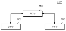
2 is a block diagram illustrating a configuration of a user terminal according to another embodiment of the present invention.
2, a
The receiving
Also, the
The
The standard content or standard documents referred to in the above-mentioned embodiments constitute a part of this specification, for the sake of simplicity of description of the specification. Therefore, it is to be understood that the content of the above standard content and some of the standard documents is added to or contained in the scope of the present invention, as falling within the scope of the present invention.
1. 3GPP TS36.213
2. 3GPP TS36.211
The foregoing description is merely illustrative of the technical idea of the present invention, and various changes and modifications may be made by those skilled in the art without departing from the essential characteristics of the present invention. Therefore, the embodiments disclosed in the present invention are intended to illustrate rather than limit the scope of the present invention, and the scope of the technical idea of the present invention is not limited by these embodiments. The scope of protection of the present invention should be construed according to the following claims, and all technical ideas within the scope of equivalents should be construed as falling within the scope of the present invention.
Claims (1)
Transmitting a PUSCH to a base station; And
HACK ACK / NACK M-PDCCH using RNTI for CRC scrambling of the PUSCH, and receiving response information including an HARQ ACK / NACK for the PUSCH through an M-PDCCH.
Applications Claiming Priority (2)
| Application Number | Priority Date | Filing Date | Title |
|---|---|---|---|
| KR1020150131099 | 2015-09-16 | ||
| KR20150131099 | 2015-09-16 |
Publications (1)
| Publication Number | Publication Date |
|---|---|
| KR20170033752A true KR20170033752A (en) | 2017-03-27 |
Family
ID=58496894
Family Applications (1)
| Application Number | Title | Priority Date | Filing Date |
|---|---|---|---|
| KR1020150136275A KR20170033752A (en) | 2015-09-16 | 2015-09-25 | Apparatus and method of transmission and reception of feedback control information for MTC UEs |
Country Status (1)
| Country | Link |
|---|---|
| KR (1) | KR20170033752A (en) |
-
2015
- 2015-09-25 KR KR1020150136275A patent/KR20170033752A/en unknown
Similar Documents
| Publication | Publication Date | Title |
|---|---|---|
| US10567939B2 (en) | Method for transmitting/receiving signal by MTC UE, and apparatus therefor | |
| US10869303B2 (en) | Method for monitoring, transmitting, and receiving downlink pre-emption indication information in new radio networks and apparatus thereof | |
| US10856307B2 (en) | Method for transmitting and receiving downlink pre-emption indication information using bitmap in new radio networks and apparatus thereof | |
| US10085249B2 (en) | Method of transmitting and receiving downlink control information and apparatuses thereof | |
| KR101856304B1 (en) | Methods for transmitting a downlink control information and Apparatuses thereof | |
| US20240008048A1 (en) | Method and device for transmitting or receiving data in next generation wireless access network | |
| KR101919636B1 (en) | Methods for Transmitting and Receiving Downlink Control Channels and Apparatuses thereof | |
| US11765735B2 (en) | Method and device for transmitting or receiving data in next generation wireless access network | |
| EP3800815A1 (en) | Devices and methods for epdcch monitoring in wireless communication systems | |
| KR20160091491A (en) | Apparatus and method of downlink data channel reception of MTC UEs | |
| US10820318B2 (en) | User terminal, radio base station and radio communication method based upon downlink control in current subframe | |
| US20140092836A1 (en) | Adjusting blind decoding of downlink control channel | |
| EP3534561B1 (en) | Method and device for allocating data channel resource for next-generation wireless access network | |
| KR101562704B1 (en) | Methods of adjusting blind decoding of downlink control channel and apparatuses thereof | |
| KR20150087805A (en) | Methods for receiving of HARQ ACK-NACK and Apparatuses thereof | |
| KR101920111B1 (en) | Methods for transmitting and receiving a signal of MTC UEs and Apparatuses thereof | |
| KR20160135013A (en) | Apparatus and method of UL physical channel transmission and reception for MTC UEs | |
| KR20150056450A (en) | Methods for Transmitting and Receiving Control Information and Apparatuses Thereof | |
| KR20150051303A (en) | Methods for random access in wireless communication systems and Apparatuses Thereof | |
| KR101896766B1 (en) | Methods for transmitting and receiving downlink control information and Apparatuses thereof | |
| KR20170033752A (en) | Apparatus and method of transmission and reception of feedback control information for MTC UEs | |
| KR20160037087A (en) | Methods for configuring Downlink resource for a MTC UE and Apparatuses thereof | |
| KR20170031589A (en) | Apparatus and method of HARQ ACK/NACK feedback timing configuration for MTC UEs | |
| KR20160040418A (en) | Methods for transmitting system information and Apparatuses thereof | |
| KR20170032799A (en) | Apparatus and method of HARQ ACK/NACK feedback resource allocation for MTC UEs |