KR20170032142A - Ice maker - Google Patents
Ice maker Download PDFInfo
- Publication number
- KR20170032142A KR20170032142A KR1020150141732A KR20150141732A KR20170032142A KR 20170032142 A KR20170032142 A KR 20170032142A KR 1020150141732 A KR1020150141732 A KR 1020150141732A KR 20150141732 A KR20150141732 A KR 20150141732A KR 20170032142 A KR20170032142 A KR 20170032142A
- Authority
- KR
- South Korea
- Prior art keywords
- ice
- sensing unit
- water
- sensing
- casing
- Prior art date
Links
Images


Classifications
-
- F—MECHANICAL ENGINEERING; LIGHTING; HEATING; WEAPONS; BLASTING
- F25—REFRIGERATION OR COOLING; COMBINED HEATING AND REFRIGERATION SYSTEMS; HEAT PUMP SYSTEMS; MANUFACTURE OR STORAGE OF ICE; LIQUEFACTION SOLIDIFICATION OF GASES
- F25C—PRODUCING, WORKING OR HANDLING ICE
- F25C1/00—Producing ice
- F25C1/22—Construction of moulds; Filling devices for moulds
- F25C1/24—Construction of moulds; Filling devices for moulds for refrigerators, e.g. freezing trays
-
- F—MECHANICAL ENGINEERING; LIGHTING; HEATING; WEAPONS; BLASTING
- F25—REFRIGERATION OR COOLING; COMBINED HEATING AND REFRIGERATION SYSTEMS; HEAT PUMP SYSTEMS; MANUFACTURE OR STORAGE OF ICE; LIQUEFACTION SOLIDIFICATION OF GASES
- F25C—PRODUCING, WORKING OR HANDLING ICE
- F25C5/00—Working or handling ice
- F25C5/02—Apparatus for disintegrating, removing or harvesting ice
-
- F—MECHANICAL ENGINEERING; LIGHTING; HEATING; WEAPONS; BLASTING
- F25—REFRIGERATION OR COOLING; COMBINED HEATING AND REFRIGERATION SYSTEMS; HEAT PUMP SYSTEMS; MANUFACTURE OR STORAGE OF ICE; LIQUEFACTION SOLIDIFICATION OF GASES
- F25C—PRODUCING, WORKING OR HANDLING ICE
- F25C2400/00—Auxiliary features or devices for producing, working or handling ice
- F25C2400/10—Refrigerator units
-
- F—MECHANICAL ENGINEERING; LIGHTING; HEATING; WEAPONS; BLASTING
- F25—REFRIGERATION OR COOLING; COMBINED HEATING AND REFRIGERATION SYSTEMS; HEAT PUMP SYSTEMS; MANUFACTURE OR STORAGE OF ICE; LIQUEFACTION SOLIDIFICATION OF GASES
- F25C—PRODUCING, WORKING OR HANDLING ICE
- F25C2600/00—Control issues
- F25C2600/04—Control means
-
- F—MECHANICAL ENGINEERING; LIGHTING; HEATING; WEAPONS; BLASTING
- F25—REFRIGERATION OR COOLING; COMBINED HEATING AND REFRIGERATION SYSTEMS; HEAT PUMP SYSTEMS; MANUFACTURE OR STORAGE OF ICE; LIQUEFACTION SOLIDIFICATION OF GASES
- F25C—PRODUCING, WORKING OR HANDLING ICE
- F25C2700/00—Sensing or detecting of parameters; Sensors therefor
- F25C2700/04—Level of water
-
- F—MECHANICAL ENGINEERING; LIGHTING; HEATING; WEAPONS; BLASTING
- F25—REFRIGERATION OR COOLING; COMBINED HEATING AND REFRIGERATION SYSTEMS; HEAT PUMP SYSTEMS; MANUFACTURE OR STORAGE OF ICE; LIQUEFACTION SOLIDIFICATION OF GASES
- F25C—PRODUCING, WORKING OR HANDLING ICE
- F25C2700/00—Sensing or detecting of parameters; Sensors therefor
- F25C2700/12—Temperature of ice trays
Abstract
Description
본 발명의 실시예는 제빙기에 관한 것으로서, 보다 구체적으로는, 공급되는 제빙수의 양을 정확하게 제어할 수 있는 제빙기에 관한 것이다.An embodiment of the present invention relates to an ice maker, and more particularly, to an ice maker capable of accurately controlling the amount of ice making water to be supplied.
일반적으로, 냉장고는 음식물을 냉장 보관하는 냉장실 및 음식물을 냉동 보관하는 냉동실을 구비하는 본체를 구비하며 본체의 후방에는 냉매를 압축하는 압축기와 냉기를 생성하기 위한 열교환기가 설치된다. 열교환기에서 발생되는 냉기는 팬에 의해 냉장실이나 냉동실 내부로 공급되고 냉장실이나 냉동실을 순환하여 온도가 상승된 공기는 다시 열교환기를 거쳐 냉장실 또는 냉동실로 공급되도록 함으로써 냉장실 또는 냉동실에 보관 중인 식품을 항상 신선한 상태로 유지할 수 있게 된다. Generally, a refrigerator has a main body having a refrigerating chamber for refrigerating and storing foods and a freezing chamber for refrigerating and storing food, and a compressor for compressing the refrigerant and a heat exchanger for generating cold air are installed at the rear of the main body. The cold air generated by the heat exchanger is supplied to the refrigerator compartment or the freezer compartment by the fan and circulated in the refrigerator compartment or the freezer compartment to supply the heated air to the refrigerator compartment or the freezer compartment through the heat exchanger. State.
과거에는 제빙기로서 단순히 냉동실에 수납이 가능하며 일정한 용적을 가지는 용기가 사용되었지만, 근래에 들어와서는 정수의 공급에서 얼음의 보관 및 취출/공급이 자동으로 이루어짐으로써 사용자의 편의성을 높인 제빙기가 냉동실 또는 냉장실에 설치된다. In recent years, ice storage and extraction / supply have been automatically performed in the supply of purified water, so that the ice maker, which improves the convenience of the user, can be stored in the freezer compartment or the refrigerator compartment. It is installed in the refrigerator room.
이러한 냉장고에 구비되는 제빙기는 물을 제빙용기에 자동으로 공급받고 제빙상태를 체크하여 제빙이 완료되면 제빙된 얼음을 제빙용기로부터 자동으로 이탈시켜 얼음보관용기에 적재하도록 하고, 제빙동작을 위한 사용자의 별도 조작이 없이 얼음을 얻을 수 있어서 최근 널리 이용되고 있다.The ice maker provided in the refrigerator automatically supplies water to the ice maker and checks the ice making condition, and when the ice maker is finished, the ice cubes are automatically released from the ice maker to be loaded on the ice maker. It is widely used in recent years because it can obtain ice without any special operation.
이와 같은 제빙기는, 정수를 공급하는 급수장치와, 얼음으로 만들어질 정수를 수용하는 트레이와, 트레이 내의 물이 모두 얼었을 때 트레이 내를 ?f어서 얼음을 취출하는 이젝터와, 이젝터를 회전시키기 위한 동력을 제공하는 모터와, 얼음을 보관하기 위한 얼음 보관 용기를 포함한다.Such an ice maker includes a water supply device for supplying purified water, a tray for receiving purified water made of ice, an ejector for extracting ice from the tray when the water in the tray is frozen, and an ejector for rotating the ejector A motor for providing power, and an ice storage container for storing ice.
이러한 구성의 제빙기는, 정수를 수납하는 트레이가 냉기를 받아 제빙을 완료하면 보관하고 있다가 만빙레버가 얼음 보관 용기 내의 얼음의 양을 체크하여 비어있는 것으로 확인되면, 트레이 하단에 설치되는 히터를 가동하여 트레이로부터 제빙된 얼음을 분리하고 이젝터로 트레이로부터 이탈시켜서 하부에 위치하는 얼음 보관 용기로 얼음을 낙하시켜서 적재하도록 하는 구조로 되어 있다.In the ice-making machine having such a configuration, when the tray storing the purified water receives the cool air and the ice-making is completed, the ice-making lever checks the amount of ice in the ice storage container and checks that the freezing lever is empty. The ice cubes are separated from the tray and separated from the tray by an ejector so that the ice cubes are dropped and placed in an ice storage container located at the bottom.
또한, 제빙기는, 이빙이 완료된 후 다음의 제빙을 위하여 냉장고 내에 마련된 물탱크 및 급수 펌프로부터 정수를 자동적으로 공급받도록 되어 있다. The ice maker is automatically supplied with purified water from a water tank and a water supply pump provided in the refrigerator for the next ice making after the ice making is completed.
제빙기의 급수를 제어하기 위한 제어 방법으로서, 급수시간을 측정하여 미리 설정된 급수 시간이 경과한 경우에 급수 밸브를 폐쇄하는 방식을 사용한다. 그러나, 이러한 급수 제어 방법은 단순히 설정된 시간 동안 트레이에 물을 공급하도록 제어할 뿐 수압의 변동과 같은 다른 요소가 고려되지 않기 때문에 트레이에 정확한 양의 물을 공급할 수 없다. 즉, 트레이 내에 급수되는 물이 너무 적어서 얼음의 크기가 너무 작게 되거나 너무 많아서 트레이로부터 오버플로우(over-flow)하여 얼음 수납통이나 기타 냉장고의 공간으로 물이 흐르게 된다.As a control method for controlling the water supply of the ice maker, a method of measuring the water supply time and closing the water supply valve when a preset water supply time has elapsed is used. However, this water supply control method merely controls water supply to the tray for a set time, and can not supply the correct amount of water to the tray because other factors such as fluctuation of water pressure are not considered. That is, the amount of water to be fed into the tray is too small to allow the ice to be over-flowed from the tray because the ice is too small or too large to allow water to flow into the ice tray or other refrigerator.
또는, 트레이의 온도를 측정하여 미리 설정된 온도 이하인 경우에는 물이 존재하지 않는 것으로 판단하여 물을 공급하는 제어 방식도 있다. 그러나 이 방법도 트레이에 공급되는 물의 양을 정확하게 제어하기는 어렵다.Alternatively, when the temperature of the tray is measured and the temperature is lower than a preset temperature, it is determined that there is no water and the water is supplied. However, this method is also difficult to accurately control the amount of water supplied to the tray.
본 발명의 실시예들은 제빙 공간 내의 제빙수의 수위를 정확하게 측정하기 위한 제빙기를 제공하기 위한 것이다.Embodiments of the present invention are intended to provide an ice maker for accurately measuring the level of ice-making water in an ice-making space.
또한, 본 발명의 실시예들은 간단한 구성으로 제빙수의 수위를 정확하게 측정하기 위한 제빙기를 제공하고자 한다.Embodiments of the present invention also provide an ice maker for accurately measuring the level of de-iced water with a simple structure.
본 발명의 실시예들은 제빙수의 수위 측정의 동작 신뢰성이 향상된 제빙기를 제공하고자 한다.Embodiments of the present invention are intended to provide an ice maker in which operational reliability of measurement of ice water level is improved.
본 발명의 일 실시예에 따르면, 제빙수를 수용하는 적어도 하나의 제빙 공간이 구비된 아이스 트레이; 및 상기 아이스 트레이의 일측에 배치되고, 모터 및 회로부가 포함되는 제어 박스를 포함하고, 상기 아이스 트레이의 상기 적어도 하나의 제빙 공간의 일측에는 센싱부가 하나이상 위치하고, 상기 센싱부는 상기 제빙 공간에 수용되는 상기 제빙수에 직접 접촉하도록 형성되며, 상기 센싱부는 상기 아이스 트레이로부터 절연되거나 이격 배치되고, 상기 센싱부에서 감지되는 정전용량 또는 통전 변화는 급수 제어부에 전기적으로 전달되는, 제빙기가 제공된다.According to an embodiment of the present invention, there is provided an ice tray having at least one ice making space for receiving iced water; And a control box disposed on one side of the ice tray and including a motor and a circuit part, wherein at least one sensing part is located at one side of the at least one ice-making space of the ice tray, and the sensing part is accommodated in the ice- Wherein the sensing unit is insulated from the ice tray or is spaced apart from the ice tray and the electrostatic capacity or current change sensed by the sensing unit is electrically transmitted to the water supply control unit.
상기 센싱부는 상기 아이스 트레이와 기 결정된 거리만큼 이격되거나 기 결정된 두께의 절연부재에 의해 절연될 수 있다.The sensing unit may be isolated from the ice tray by a predetermined distance or by an insulation member having a predetermined thickness.
상기 센싱부의 외부는 절연 고정부가 구비되며, 상기 절연 고정부의 일측에 제빙트레이의 제빙수 저장공간부 방향으로 개구부가 형성될 수 있다.The sensing unit may be provided with an insulating fixing unit, and an opening may be formed on one side of the insulating fixing unit in the direction of the ice-making water storage space of the ice-making tray.
상기 제어 박스 또는 상기 아이스 트레이 일측에 온도 센서가 배치되며, 상기 온도 센서의 외측에는 상기 온도 센서를 보호하는 케이싱이 형성될 수 있다.A temperature sensor may be disposed on one side of the control box or the ice tray, and a casing may be formed on the outside of the temperature sensor to protect the temperature sensor.
상기 센싱부는 하나 이상의 금속 재질 봉 형상의 정전 용량 또는 통전전극 센서이며, 상기 센싱부는 부도체에 의해 고정되거나 케이싱에 의해 보호될 수 있다.The sensing unit may be one or more metal rod-shaped capacitive or energizing electrode sensors, and the sensing unit may be fixed by an insulator or protected by a casing.
상기 케이싱의 적어도 일부는 금속 재질일 수 있다.At least a part of the casing may be made of a metal material.
상기 케이싱은 전기적 접속되는 접속선에 의해 상기 급수 제어 관련부와 연결될 수 있다.The casing may be connected to the water supply control related part by a connection line electrically connected thereto.
상기 전기적 접속은 웰딩(welding), 압입, 브레이징(brazing), 단자 삽입, 리베팅(riveting) 중 하나에 의할 수 있다.The electrical connection may be in one of welding, indentation, brazing, terminal insertion, or riveting.
상기 센싱부는 상기 아이스 트레이의 제빙 적정 수위부의 상하 10 mm 이내에 위치할 수 있다.The sensing unit may be located within 10 mm above and below the proper ice level of the ice tray.
상기 센싱부에 온도 센서가 일체로 형성되거나 상기 센싱부와 별개의 온도 센서가 형성될 수 있다.A temperature sensor may be formed integrally with the sensing unit or a temperature sensor may be formed separately from the sensing unit.
상기 센싱부는 온도센서의 금속 케이싱을 포함할 수 있다.The sensing unit may include a metal casing of a temperature sensor.
상기 센싱부의 일측에는 전기적 센싱 신호 증폭 출력부가 구비될 수 있다.An electrical sensing signal amplification output may be provided on one side of the sensing unit.
상기 센싱부는 상기 제빙 공간의 외곽라인부에 배치되어 제빙수와 직접 접촉하며 센싱할 수 있다.The sensing unit may be disposed in an outer line portion of the ice making space and may be in direct contact with the ice making water.
상기 정전 용량 또는 통전 변화를 감지하는 센싱부와 온도 센서가 하나의 케이싱에 의해 보호될 수 있다.The sensing unit and the temperature sensor for sensing the capacitance change or the change in the energization can be protected by a single casing.
상기 정전 용량 또는 통전 변화를 감지하는 센싱부와 온도 센서가 하나의 인쇄 회로 기판(PCB) 상에 형성될 수 있다.The sensing unit and the temperature sensor for sensing the electrostatic capacity or the change in the energization may be formed on one printed circuit board (PCB).
상기 센싱부는 상기 센싱부와 연결되는 회로부와 하나의 기판 상에 형성될 수 있다.The sensing unit may be formed on one substrate and a circuit unit connected to the sensing unit.
상기 케이싱 중 급수 여부를 센싱하는 일부분은 다른 부분보다 얇게 형성될 수 있다.A portion of the casing sensing whether water is supplied may be formed thinner than other portions.
상기 케이싱의 내부의 적어도 일부는 절연 물질로 충진, 몰딩(molding) 또는 코팅될 수 있다.At least a portion of the interior of the casing may be filled, molded or coated with an insulating material.
상기 봉 형상의 센서는 상기 아이스 트레이 측으로 3 mm 이하로 돌출될 수 있다.The bar sensor may protrude to the ice tray side by 3 mm or less.
상기 통전 변화는 3 V 이상의 전압에 대하여 2.5 V 이상의 전압의 감지 여부로 결정될 수 있다.The energization change can be determined by detecting a voltage of 2.5 V or more with respect to a voltage of 3 V or more.
상기 온도 센서의 상기 케이싱은 실리콘 재질로 형성될 수 있다.The casing of the temperature sensor may be formed of a silicon material.
상기 온도 센서의 상기 케이싱을 통해 정전 용량을 감지하여 급수 수위를 감지할 수 있다.The water level can be sensed by sensing the capacitance through the casing of the temperature sensor.
상기 케이싱은 이탈 방지 구조를 포함할 수 있다.The casing may include an escape prevention structure.
상기 이탈 방지 구조는 원형 구조, 단차 구조 또는 경사 구조를 포함할 수 있다.The departure-avoidance structure may include a circular structure, a stepped structure, or an inclined structure.
상기 센싱부에서 정전 용량을 센싱하는 경우, 상기 센싱부와 상기 회로부 사이는 리드선에 의해 연결될 수 있다.When the capacitance is sensed by the sensing unit, the sensing unit and the circuit unit may be connected by a lead wire.
상기 센싱부에서 정전 용량을 센싱하는 경우, 상기 리드선은 쉴드(shield) 처리된 리드선일 수 있다.When the sensing unit senses the capacitance, the lead wire may be a shielded lead wire.
본 발명의 다른 실시예에 따르면, 냉장실 및 냉동실 중 적어도 하나를 포함하는 챔버; 상기 챔버 내에 배치되는 제빙기; 상기 제빙기에 제빙수를 공급하는 워터 밸브; 및 상기 워터 밸브를 제어하는 제어부를 포함하고, 상기 제빙기의 일측에는 제빙수가 수용되는 트레이가 형성되고, 상기 트레이의 일측에는 전극이 구비되며, 상기 전극에 의해 감지되는 전기적 신호 변화가 상기 제어부에 전송되는, 제빙기가 제공된다.According to another embodiment of the present invention, there is provided a refrigerator comprising: a chamber including at least one of a refrigerating chamber and a freezing chamber; An ice maker disposed in the chamber; A water valve for supplying iced water to the icemaker; And a controller for controlling the water valve, wherein a tray for receiving ice-making water is formed on one side of the ice-maker, an electrode is provided on one side of the tray, and an electrical signal change sensed by the electrode is transmitted to the controller An ice maker is provided.
본 발명의 또 다른 실시예에 따르면, 냉장고에 포함되는 제빙기에 있어서, 상기 제빙기의 정전 용량 또는 전극의 통전 변화에 의한 급수 신호가 상기 제빙기 내의 제어부 또는 냉장고의 제어부로 전송되는, 제빙기가 제공된다.According to another embodiment of the present invention, in the ice maker included in the refrigerator, a water supply signal caused by a change in energization of the electrostatic capacity of the ice-maker or the electrode is transmitted to a controller of the ice-maker or a controller of the refrigerator.
본 발명의 또 다른 실시예에 따르면, 냉장고에 포함되는 제빙기에 있어서, 상기 제빙기에 포함되는 온도 센서에 의한 급수 제어 또는 상기 제빙기 내의 정전 용량 또는 전극의 통전 변화에 의한 급수 제어가 수행되거나, 상기 온도 센서에 의한 급수 제어와 상기 제빙기의 정전 용량 또는 전극의 통전 변화에 의한 급수 제어가 같이 수행되는, 제빙기가 제공된다.According to another embodiment of the present invention, in the ice making machine included in the refrigerator, water supply control by a temperature sensor included in the ice-making machine or water supply control by change in energization of the electrostatic capacity or the electrode in the ice- The water supply control by the sensor and the water supply control by the capacitance of the icemaker or the change of the energization of the electrode are performed in the same manner.
본 발명의 또 다른 실시예에 따르면, 제빙기를 포함하는 냉장고에 있어서, 상기 제빙기에 포함되는 온도 센서에 의한 급수 제어 또는 상기 제빙기 내의 정전 용량 또는 전극의 통전 변화에 의한 급수 제어가 수행되거나, 상기 온도 센서에 의한 급수 제어와 상기 제빙기의 정전 용량 또는 전극의 통전 변화에 의한 급수 제어가 같이 수행되는, 냉장고가 제공된다.According to another embodiment of the present invention, in the refrigerator including the ice maker, the water supply control by the temperature sensor included in the ice-maker or the water supply control by the change in the electrostatic capacitance or the energization of the electrode is performed, The water supply control by the sensor and the water supply control by the capacitance of the icemaker or the change of the energization of the electrode are performed together.
1회 이상의 급수 제어를 수행할 수 있다.It is possible to perform water feed control more than once.
1회 급수후 센싱 유무룰 판별할 수 있다.After one water supply, it is possible to determine the presence or absence of sensing.
본 발명의 실시예들에 의하면, 센싱부의 케이싱을 이용함으로써, 제빙 공간의 제빙수의 수위를 정확하게 측정할 수 있다.According to the embodiments of the present invention, by using the casing of the sensing portion, the level of the ice-making water in the ice-making space can be accurately measured.
또한, 제빙 공간의 제빙수의 수위를 정확하게 측정함으로써, 적절한 크기의 얼음을 형성할 수 있으며 아이스 트레이에서 제빙수가 오버플로우하는 것을 방지할 수 있다. In addition, by accurately measuring the level of the ice-making water in the ice-making space, it is possible to form an ice of an appropriate size and to prevent the ice-making water from overflowing in the ice tray.
또한, 간단한 구성으로 제빙 공간의 제빙수를 정확하게 측정함으로써, 제빙수 측정 동작의 신뢰성이 향상될 수 있다. In addition, the reliability of the ice-making number measuring operation can be improved by accurately measuring the ice-making number of the ice-making space with a simple structure.
도 1은 본 발명의 일 실시예에 따른 제빙기를 나타낸 도면
도 2는 본 발명의 일 실시예에 따른 센싱부를 나타내는 도면
도 3은 본 발명의 다른 실시예에 따른 센싱부를 나타내는 도면
도 4는 본 발명의 또 다른 실시예에 따른 센싱부를 나타내는 도면
도 5는 본 발명의 또 다른 실시예에 따른 센싱부와 제 1 연결선 간의 결합 상태를 나타내는 도면
도 6은 본 발명의 또 다른 실시예에 따른 센싱부와 제 1 연결선 간의 다른 결합 상태를 나타내는 도면
도 7은 본 발명의 다른 실시예에 따른 제빙기를 나타내는 도면
도 8은 본 발명의 다른 실시예에 따른 제빙기의 일부를 확대한 도면
도 9는 본 발명의 또 다른 실시예에 따른 제빙기의 일부를 확대한 단면도
도 10은 트위스트 제빙기에서 센싱부가 형성된 것을 나타내는 도면1 is a view showing an ice maker according to an embodiment of the present invention;
2 is a diagram showing a sensing unit according to an embodiment of the present invention;
3 is a view showing a sensing unit according to another embodiment of the present invention;
4 is a view showing a sensing unit according to another embodiment of the present invention;
5 is a view showing a state of engagement between a sensing part and a first connection line according to another embodiment of the present invention;
6 is a view showing another coupling state between a sensing part and a first connection line according to another embodiment of the present invention;
7 is a view showing an ice maker according to another embodiment of the present invention;
8 is an enlarged view of a part of an ice maker according to another embodiment of the present invention;
9 is an enlarged cross-sectional view of a part of an ice maker according to another embodiment of the present invention
10 is a view showing a state in which a sensing portion is formed in a twisted ice maker
이하, 도면을 참조하여 본 발명의 구체적인 실시예를 설명하기로 한다. 그러나 이는 예시적 실시예에 불과하며 본 발명은 이에 제한되지 않는다.Hereinafter, specific embodiments of the present invention will be described with reference to the drawings. However, this is an exemplary embodiment only and the present invention is not limited thereto.
본 발명을 설명함에 있어서, 본 발명과 관련된 공지기술에 대한 구체적인 설명이 본 발명의 요지를 불필요하게 흐릴 수 있다고 판단되는 경우에는 그 상세한 설명을 생략하기로 한다. 그리고, 후술되는 용어들은 본 발명에서의 기능을 고려하여 정의된 용어들로서 이는 사용자, 운용자의 의도 또는 관례 등에 따라 달라질 수 있다. 그러므로 그 정의는 본 명세서 전반에 걸친 내용을 토대로 내려져야 할 것이다.In the following description, a detailed description of known functions and configurations incorporated herein will be omitted when it may make the subject matter of the present invention rather unclear. The following terms are defined in consideration of the functions of the present invention, and may be changed according to the intention or custom of the user, the operator, and the like. Therefore, the definition should be based on the contents throughout this specification.
본 발명의 기술적 사상은 청구범위에 의해 결정되며, 이하 실시예는 진보적인 본 발명의 기술적 사상을 본 발명이 속하는 기술분야에서 통상의 지식을 가진자에게 효율적으로 설명하기 위한 일 수단일 뿐이다.The technical idea of the present invention is determined by the claims, and the following embodiments are merely a means for efficiently describing the technical idea of the present invention to a person having ordinary skill in the art to which the present invention belongs.
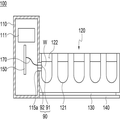
도 1은 본 발명의 일 실시예에 따른 제빙기(100)를 나타낸 도면이다. 1 is a view illustrating an
도 1을 참조하면, 제빙기(100)는 아이스 트레이(120), 이젝터(미도시됨), 및 제어 박스(110)를 포함할 수 있다. Referring to FIG. 1, the
아이스 트레이(120)는 그 내부에 기 결정된 내면(121)을 형성하며, 물을 수용하는 복수의 제빙 공간(122)을 가질 수 있다. 아이스 트레이(120)의 내부에는 복수 개의 격벽이 형성되어 복수 개의 제빙 공간(122)으로 분리할 수 있다. 이 때, 아이스 트레이(120) 내의 분리된 각 제빙 공간(122)은 이젝터의 이젝터 핀과 대응하여 형성될 수 있다. 아이스 트레이(120)의 내주면은 이젝터 핀이 회전하여 얼음을 이빙할 수 있도록 이젝터 핀의 길이에 대응하는 반경을 가지는 반원호 형상으로 마련될 수 있다. The
이젝터는 아이스 트레이(120) 내의 얼음을 이빙시키는 역할을 할 수 있다. 이젝터는 제어 박스(110) 내의 모터(111)와 연결된 이젝터 축 및 이젝터 축에 상호 이격하여 형성되는 복수 개의 이젝터 핀을 포함할 수 있다. 이젝터 핀은 이젝터 축을 중심으로 기 결정된 방향으로 회전하여 아이스 트레이(120) 내의 얼음을 이빙시킬 수 있다.The ejector can serve to freeze the ice in the
히터(130)는 아이스 트레이(120)의 하부에 마련될 수 있다. 이 때, 히터(130)는 아이스 트레이(120)의 외주면과 면접촉하여 마련되게 될 수 있다. 히터(130)는 아이스 트레이(120)의 길이 방향을 따라 마련될 수 있다. 히터(130)는 소정 면적에 걸쳐 열을 발생시킬 수 있다. 히터(130)는 시즈 히터(sheath heater), 코드 히터(cord heater) 및 면상 히터 중 하나로 이루어질 수 있다. 또는, 히터(130)는 코드 히터가 면상의 절연체로 절연되는 형태일 수도 있다. 히터(130)는 박형으로 제조될 수 있는데, 예를 들어, 히터(130)의 두께는 0 초과 1mm 이하로 이루어질 수 있다. 히터(130)의 두께의 하한은 히터(130)를 구성하는 발열체 및 절연 부재 등의 재질에 따라 당업자의 수준에서 적절하게 설정될 수 있다. 히터(130)가 박형으로 제조되어 히터(130)의 열 용량을 작게 함으로써, 히터(130)는 빠른 시간 내에 소정 온도로 상승될 수 있게 된다. 이 경우, 히터(130)에 사용되는 전력 소모를 줄일 수 있게 된다. 히터(130)는 예를 들어, PTC(Positive Temperature Coefficient) 히터가 사용될 수 있으나, 이에 한정되는 것은 아니다.The
히터(130)의 하부에는 커버(140)가 형성될 수 있다. 커버(140)는 히터(130)를 아이스 트레이(120) 측으로 밀착시키는 역할을 할 수 있고, 외부로부터 히터(130) 및 아이스 트레이(120)를 보호하는 역할을 할 수도 있다. 또한, 커버(140)는 아이스 트레이(120)로부터 낙하하는 물이나 서리가 냉장고의 다른 공간으로 낙하하는 것을 방지하는 역할을 할 수도 있다.The
제어 박스(110)는 아이스 트레이(120)의 일측에 마련될 수 있다. 제어 박스(110)는 아이스 트레이(120)의 일측에서 아이스 트레이(120)와 결합될 수 있다. 제어 박스(110)에는 제빙기(100)의 전체 동작을 제어하는 제어부(미도시)가 마련될 수 있다. 또한, 제어 박스(110)에는 이젝터를 소정 방향으로 회전시키는 이빙 모터(111)가 마련될 수 있다. 제어 박스에는 이빙 모터 및 히터에 전원을 공급하는 전원 공급부(미도시)가 마련될 수 있다. The
여기서, 제어부는 예를 들어, 이젝터의 회전 위치 또는 이젝터의 동작 시간 경과에 따라 히터(130)의 온 또는 오프 동작을 제어할 수 있다. 구체적으로, 제어부(미도시)는 아이스 트레이(120)의 온도가 기설정된 제빙 온도(즉, 아이스 트레이(120) 내의 제빙수가 완빙되는 온도)에 도달하면, 히터(130)를 동작시킬 수 있다. Here, the control unit can control the ON or OFF operation of the
다음으로, 제어부는 이젝터를 회전하여 아이스 트레이(120) 내의 얼음을 이빙시키기 시작한다. 제어부는 이젝터의 위치가 히터를 지나는 경우, 히터(130)를 오프(OFF)시킬 수 있다. 이 경우, 얼음을 녹이는데 소요되는 전력 소모를 줄일 수 있게 된다. 이 때, 제어부는 위치 센서를 통해 이젝터의 홈 위치를 확인한 후 이빙 모터(111)로부터 입력되는 펄스 신호수를 누적하여 연산함으로써, 현재 이젝터의 위치를 확인할 수 있게 된다.Next, the control unit rotates the ejector, and starts to ice the ice in the
여기서는, 제어부가 히터(130)를 모두 온(ON) 시킨 후, 이젝터가 히터(130)를 지났을 때 히터(130)를 오프(OFF)시키는 것으로 설명하였으나, 이에 한정되는 것은 아니며 그 이외의 다양한 방식으로 히터(130)의 동작을 조절할 수 있다. Here, it is described that the
또한, 여기서는 제어부가 이젝터의 위치에 따라 히터(130)를 제어하는 것으로 설명하였으나, 이에 한정되는 것은 아니며 제어부는 이젝터를 회전시킨 후 경과 시간에 따라 히터(130)를 제어할 수도 있다.Here, the control unit controls the
본 발명의 일 실시예에 따른 제빙기(100)는 센싱부(160)를 포함할 수 있다. 센싱부(160)는 아이스 트레이(120) 내에서의 여러 정보를 센싱하기 위한 것일 수 있다. 센싱부(160)는 아이스 트레이(120)와 제어 박스(110)의 사이에 배치될 수 있다. 센싱부(160)의 일측은 아이스 트레이(120)에 형성된 복수의 제빙 공간(122) 중 하나에 노출되어 제빙 공간(122)의 조건에 관한 여러 정보를 센싱할 수 있다. 센싱부(160)는 제어 박스(110) 내에 위치하는 회로부(150)와 전기적으로 연결되어 센싱부(160)에서 센싱한 정보를 회로부(150)로 전송하고, 이를 통해 제빙기(100)의 동작이 제어될 수 있다. 본 발명의 일 실시에에 따르면, 센싱부(160)와 회로부(150) 간을 연결하기 위하여 제 1 연결선(170) 및 제 2 연결선(180)이 사용될 수 있다. 여기에서, 센싱부(160)는 제빙 공간(122) 내에 수용되는 제빙수에 직접 접촉하도록 형성될 수 있다. 센싱부(160)가 제빙수에 직접 노출됨으로써, 센싱부(160)에 의해 센싱되는 정전용량 또는 통전 변화와 같은 전기적 신호의 감지를 보다 확실하게 할 수 있다.The
여기에서, 회로부(150)는 인쇄회로기판(PCB)에 배선이 연결되어 여러 구성 간을 연결하거나, 소자가 부착되는 경우 뿐만 아니라, 인쇄회로기판 없이 배선으로 연결되는 경우도 포함할 수 있다. Here, the
센싱부(160)는 아이스 트레이(120) 및/또는 제빙 공간(122) 내에 수용되는 제빙수(W)에 관한 여러 정보를 센싱할 수 있는데, 특히 아이스 트레이(120) 및 제빙수(W)의 온도라던지 제빙수(W)의 공급 수위를 센싱할 수 있다. 이를 통해, 간단한 구성으로도 아이스 트레이(120)에 공급되는 제빙수(W)의 양을 정확하게 감지할 수 있어서 최적의 얼음을 형성할 수 있다.The
또한, 센싱부(160)는 아이스 트레이(120)와 기 결정된 거리만큼 이격되거나 기 결정된 두께의 절연부재에 의해 절연될 수 있다. 이를 통해 센싱부(160)에 의해 감지되는 전기적 신호가 아이스 트레이(120) 측으로 흘러나가서 전기적 신호가 약해지는 것을 방지할 수 있다.The
도 2는 본 발명의 일 실시예에 따른 센싱부(160)를 나타내는 도면이다.2 is a diagram illustrating a
도 2를 참조하면, 센싱부(160)는 케이싱(161)의 내부에 온도센서(163)를 포함할 수 있다. 앞서 설명한 바와 같이, 센싱부(160)의 케이싱(161)은 그 일측이 제빙 공간(122)에 노출될 수 있다. 도 2에 따르면, 케이싱(161)의 우측면이 제빙 공간(122)에 노출될 수 있다. 케이싱(161)은 전도성 재질로 이루어져서 전류가 흐르는 것이 가능하다. 예를 들어, 케이싱(161)은 금속 재질로 형성될 수 있다.Referring to FIG. 2, the
케이싱(161)의 내부에는 온도센서(163)가 위치할 수 있다. 온도센서(163)는 아이스 트레이(120)의 온도를 검지할 수 있다. 온도센서(163)는 제 2 연결선(180)을 통해 회로부(150)와 연결되며, 온도센서(163)를 통해 검지된 온도 정보를 제 2 연결선(180)을 통해 회로부로 전달할 수 있다.A
본래, 센싱부(160)는 아이스 트레이(120)의 온도를 측정하는데 중점을 두고 있는 것이나, 센싱부(160)의 케이싱(161)이 전도성 재질인 것에 착안하여 케이싱(161)을 통해 제빙 공간(122) 내의 제빙수(W)의 수위를 확인하는 수위 센서로의 역할도 행할 수 있다. 즉, 센싱부(160)의 케이싱(161)이 수위 센서의 전극의 역할을 할 수 있다. 제빙 공간(122) 내의 제빙수(W)의 수위가 케이싱(161)의 위치까지 도달하면 케이싱(161)을 통해 흐르는 전류가 통전(通電)하게 되어서 제빙수(W)의 수위가 케이싱(161)의 위치까지 도달하였음을 감지할 수 있다. 이러한 방식을 통해 제빙수(W)의 수위를 정확하게 확인할 수 있다.The
케이싱(161)의 내측에는 케이싱(161)과 전기적으로 연결된 연결 부재(162)가 배치되고 연결 부재(162)와 회로부(150) 간이 제 1 연결선(170)을 통해 전기적으로 연결될 수 있다. 따라서, 케이싱(161)을 통해 감지된 제빙수(W)의 수위 정보가 연결 부재(162)를 통해 회로부(150)로 전달될 수 있다.A
케이싱(161)의 내측의 기타 공간은 절연성 물질로 구성된 충진부(165)가 차지하여 케이싱(161) 내부에 위치하는 구성 간을 절연할 수 있다.The other space inside the
케이싱(161)은 아이스 트레이(120)의 제빙 적정 수위에 위치할 수 있다. 제빙 적정 수위란, 아이스 트레이(120)의 제빙 공간(122) 내에 수용되는 제빙수(W)가 아이스 트레이(120)로부터 넘치거나 제빙수(W)가 적어서 만들어지는 얼음이 작게 되는 것이 없는 적정 수위를 지칭하는 것일 수 있다.The
도 3은 본 발명의 다른 실시예에 따른 센싱부(160a)를 나타내는 도면이다. 앞선 실시예와 대응되는 구성에 관한 설명은 생략한다.3 is a diagram illustrating a
도 3을 참조하면, 본 실시예에 따른 센싱부(160a)에서는 케이싱(161a)의 일부가 절개되고, 케이싱(161a)의 절개된 부분을 관통하여 접촉부재(162a)가 배치될 수 있다. 접촉부재(162a)는 케이싱(161a)을 관통하여 배치되며, 일측이 제빙 공간(122)에 노출될 수 있다. 접촉부재(162a)는 전도성 재질인 금속으로 형성될 수 있다. 본 실시예에서는, 앞선 실시에서와 달리, 접촉부재(162a)가 제빙 공간(122)에 노출되어 제빙 공간 내의 제빙수(W)와 직접 접촉할 수 있기 때문에, 접촉부재(162a)가 전도성 재질이면 되고, 케이싱(161a)이 전도성일 필요는 없을 수 있다. 접촉부재(162a)와 회로부(150) 간은 제 1 연결선(170)을 통해 전기적으로 연결될 수 있다. 따라서, 접촉부재(162a)를 통해 감지된 제빙수(W)의 수위 정보가 회로부(150)로 전달될 수 있다.Referring to FIG. 3, in the
도 4는 본 발명의 또 다른 실시예에 따른 센싱부(160b)를 나타내는 도면이다. 앞선 실시예와 대응되는 구성에 관한 설명은 생략한다.4 is a diagram illustrating a
도 4를 참조하면, 본 실시예에 따른 센싱부(160b)에서는 케이싱(161)이 직접 제 1 연결선(170)을 통해 회로부(150)와 연결될 수 있다. 케이싱(161)이 제빙 공간(122)에 노출되는 일측이 아닌 타측에 제 1 연결선(170)과 접합하는 연결부(161-1)가 형성될 수 있다. 도 4에 따르면, 케이싱(161)이 제빙 공간(122)에 노출되는 일측이 우측이기 때문에, 연결부(161-1)는 좌측에 형성될 수 있다. 그러나, 연결부(161-1)의 위치가 이에 한정되는 것은 아니다.4, in the
도 5는 본 발명의 또 다른 실시예에 따른 센싱부(160b)와 제 1 연결선(170) 간의 결합 상태를 나타내는 도면이다.5 is a view illustrating a state of coupling between the
도 5를 참조하면, 센싱부(160b)에 형성된 연결부(161-1)와 제 1 연결선(170)간의 접합 상태를 견고하게 하기 위하여, 압입을 이용할 수 있다. 도 5(a)에 도시되는 바와 같이, 연결부(161-1)와 제 1 연결선(170) 간을 기 결정된 접착력으로 연결한 상태에서 센싱부(160b)가 제어 박스(110)의 아이스 트레이(120) 측에 형성되는 수용부(115) 내로 압입될 수 있다. 센싱부(160b)가 수용부(115) 내로 압입됨으로써, 센싱부(160b)와 수용부(115) 간이 밀착될 수 있다. 이로 인하여, 연결부(161-1)와 제 1 연결선(170) 간의 접합 상태가 견고하게 고정될 수 있다. 연결부(161-1)와 제 1 연결선(170) 간이 견고하게 고정된 상태는 도 5(b)에 도시된 바와 같다.Referring to FIG. 5, indentation may be used to firmly connect the connection portion 161-1 formed in the
도 6은 본 발명의 또 다른 실시예에 따른 센싱부(160b)와 제 1 연결선(170) 간의 다른 결합 상태를 나타내는 도면이다.6 is a view illustrating another coupling state between the
도 6을 참조하면, 센싱부(160b)의 연결부(161-1) 측에 웰딩(welding)을 행하여 웰딩부(161-2)를 형성할 수 있다. 이로 인하여, 웰딩부(161-2)가 연결부(161-1) 상을 덮음으로써, 연결부(161-1)와 제 1 연결선(170) 간의 접합을 견고하게 고정할 수 있다. 상기 웰딩은 전기 용접 및 아크 용접 등을 포함하는 스폿 용접일 수 있다.Referring to FIG. 6, a welding portion 161-2 may be formed by welding to the connection portion 161-1 side of the
도 7은 본 발명의 다른 실시예에 따른 제빙기(100)를 나타내는 도면이다. 본 실시예에 있어서, 앞선 실시예와 대응되는 구성에 관한 설명은 생략한다.7 is a view showing an
도 7을 참조하면, 제빙기(100)는 센싱부(160) 대신 수위 센싱 부재(190)를 포함할 수 있다. 앞선 실시예에서의 센싱부(160)는 온도 센서(163)를 내재하고 있는 것에 반해, 수위 센싱 부재(190)는 온도 센서(163)를 포함하지 않고 단지 제빙 공간(122) 내의 제빙수(W)의 수위를 센싱하는 역할을 한다. 수위 센싱 부재(190)는 아이스 트레이(120)와 제어 박스(110)의 사이에 배치되며, 수위 센싱 부재(190)를 배치하기 위하여 아이스 트레이(120)에는 삽입부(115a)가 형성될 수 있다.Referring to FIG. 7, the
수위 센싱 부재(190)는 일측에 제빙 공간(122)에 노출되는 금속 부재(191)와 금속 부재(191) 주위를 감싸는 절연 부재(192)를 포함할 수 있다. 금속 부재(191)는 제 1 연결선(170)을 통해 회로부(150)와 전기적으로 연결될 수 있다. 금속 부재(191)는 길이 방향이 아이스 트레이(120)와 제어 박스(110) 간을 관통하도록 배치되는 금속 봉일 수 있다. The water level sensing member 190 may include a
금속 부재(191)의 일측이 제빙 공간(122)에 노출되기 때문에, 제빙 공간(122) 내의 제빙수(W)가 금속 부재(191)의 위치에 도달하게 되면, 제빙수(W)가 금속 부재(191)와 접촉할 수 있다. 따라서, 앞선 센싱부(160)의 경우와 유사하게, 금속 부재(191)가 수위 센서의 전극의 역할을 할 수 있다. 제빙 공간(122) 내의 제빙수(W)의 수위가 금속 부재(191)의 위치까지 도달하면 금속 부재(191)을 통해 흐르는 전류가 통전(通電)하게 되어서 제빙수(W)의 수위가 금속 부재(191)의 위치까지 도달하였음을 감지할 수 있다. 이러한 방식을 통해 제빙수(W)의 수위를 정확하게 확인할 수 있다. 이 경우, 3 V 이상의 전압을 걸었을 때, 2.5 V 이상의 전압을 감지함으로써 확인할 수 있다.When the ice making water W in the
도 8은 본 발명의 다른 실시예에 따른 제빙기(100)의 일부를 확대한 도면이다.8 is an enlarged view of a part of the
도 8을 참조하면, 금속 부재(191)는 제빙 공간(122) 내의 제빙수(W)와의 접촉을 용이하게 하기 위하여 기 결정된 간격(d)만큼 제빙 공간(122) 측으로 돌출될 수 있다. 다만, 금속 부재(191)가 지나치게 제빙 공간(122) 측으로 돌출되면 제빙수(W)가 얼음이 되었을 때 금속 부재(191)에 걸려서 이빙되지 않을 수 있다. 이를 방지하기 위해, 금속 부재(191)의 돌출 간격(d)은 3 mm 이하로 할 수 있다.8, the
본 실시예에서는 금속 부재(191)가 하나인 것을 예시로서 설명하고 있지만, 이에 한정되는 것은 아니다. 금속 부재(191)는 복수개일 수 있어서, 제빙수(W)의 수위를 단계별로 감지할 수도 있다. 또한, 수위 센싱 부재(190)가 센싱부(160)를 대체하는 것 뿐만 아니라 수위 센싱 부재(190)와 센싱부(160)가 같이 사용되는 것도 가능하다. 이 경우에는, 센싱부(160)와 수위 센싱 부재(190) 모두 회로부(150)와 연결되며, 각각이 서로 다른 위치에서 제빙수(W)의 수위를 감지할 수 있다.In the present embodiment, one
도 9는 본 발명의 또 다른 실시예에 따른 제빙기의 일부를 확대한 단면도이다.9 is an enlarged cross-sectional view of a part of an icemaker according to another embodiment of the present invention.
도 9를 참조하면, 본 실시예에 따른 제빙기에서의 센싱부(160)의 케이싱은 적어도 일부가 실리콘 재질로 형성될 수 있으며, 센싱부(160)의 케이싱 중 아이스 트레이(120) 측으로 노출되는 측은 금속으로 형성될 수 있다.Referring to FIG. 9, at least a part of the casing of the
센싱부(160)의 케이싱) 내에는 정전용량 센서(210), 통전 센서(미도시됨) 및 온도 센서(미도시됨) 중 적어도 하나가 그 내부에 포함될 수 있고, 센싱부(160)의 케이싱의 내측의 적어도 일부는 절연물질로 몰딩(molding)되거나 코팅(coating)될 수 있다.At least one of a
센싱부(160)의 케이싱에 있어서, 아이스 트레이(120)의 제빙 공간(122) 내의 수위를 측정하기 위한 정전용량 센서(210) 및 정전용량 센서(210)의 측정값과 비교되는 비교값을 저장하고 이 둘 간을 비교하여 제빙 공간(122) 내의 수위를 판단하는 회로부가 하나의 기판(200)에 형성될 수 있다.A comparison value to be compared with the measured values of the
또한, 정전용량 센서(210) 및 통전 센서는 온도 센서와 하나의 기판(200)에 배치될 수 있다.In addition, the
센싱부(160)의 케이싱 중 외부로 노출되어 급수 여부를 센싱하는 일부의 두께(d2)는 다른 부분의 두께(d1) 보다 얇게 형성되어 케이싱(160)을 통한 센싱능력이 향상될 수 있다.The thickness d2 of the
도 9에서는 센싱부(160)의 케이싱이 아이스 트레이(120)의 하나의 제빙 공간(122)에 배치되는 것으로 도시하고 있지만, 이에 한정되는 것은 아니고, 복수의 제빙 공간(122) 각각에 센싱부(160)의 케이싱이 배치될 수도 있다.9 shows that the casing of the
센싱부(160)의 케이싱에는 제어 박스(110) 또는 아이스 트레이(120)로부터 이탈되는 것을 방지하기 위한 단차 구조 또는 경사 구조가 형성될 수 있다.The casing of the
또한, 정전용량 센서(210)를 통해 정전 용량을 센싱하는 경우, 정전용량 센서(210)와 회로부 사이에는 리드선에 의해 연결될 수 있다. 연결선은 쉴드(shield) 처리된 리드선일 수 있다.When the electrostatic capacitance is sensed through the
앞선 실시예들에서, 본 발명의 센싱부 및 케이싱이 이젝터를 포함하는 제빙기에 적용되는 것으로 설명하고 있지만, 이에 한정되는 것은 아니다. 도 10은 트위스트 제빙기(300)에서 센싱부(330)가 형성된 것을 나타내는 도면이다.In the above embodiments, the sensing unit and the casing of the present invention are applied to the ice maker including the ejector, but the present invention is not limited thereto. 10 is a view showing that the
도 10을 참조하면, 트위스트 제빙기(300)에서도 급수를 제어하기 위한 센싱부(330)가 형성될 수 있다. 트위스트 제빙기(300)는 모터를 통해 바디(310)를 비틀어서 아이스 트레이(310) 내에 제빙된 얼음을 이빙시킬 수 있다. 센싱부(330)가 연결선(340)을 통해 제어부와 연결되는 것은 앞선 실시예와 같을 수 있다.Referring to FIG. 10, a
그 외에도 오거(auger)식 제빙기에서도 물이 수용되는 아이스 트레이 내의 급수를 제어하기 위하여 센싱부가 설치될 수 있다. 뿐만 아니라, 냉장고, 세탁기, 탈수기, 건조기, 가습기, 제습기, 연료펌핑모듈과 같이 물 기타 액체가 들어가는 다양한 기기에 센싱부, 온도 센서가 삽입되어서 급수를 제어할 수 있다. 이 경우에는 센싱 제어 신호의 출력을 높이기 위해서 센싱 제어 시그널 출력부를 센싱부의 일측에 형성할 수 있다.In addition, the auger type ice maker may be provided with a sensing unit for controlling water supply in the ice tray in which water is received. In addition, the water supply can be controlled by inserting a sensing part and a temperature sensor in various devices such as a refrigerator, a washing machine, a dehydrator, a dryer, a humidifier, a dehumidifier, and a fuel pump module. In this case, a sensing control signal output unit may be formed on one side of the sensing unit to increase the output of the sensing control signal.
또한, 본 발명의 일 실시예에 의한 제빙기는 1회 이상의 급수 제어를 수행할 수 있으며, 1회 급수 후 센싱 유무를 판별할 수 있다.Also, the ice maker according to an embodiment of the present invention can perform at least one water supply control, and can determine whether or not the water is sensed once after the water supply.
이상에서 대표적인 실시예를 통하여 본 발명에 대하여 상세하게 설명하였으나, 본 발명이 속하는 기술분야에서 통상의 지식을 가진 자는 상술한 실시예에 대하여 본 발명의 범주에서 벗어나지 않는 한도 내에서 다양한 변형이 가능함을 이해할 것이다. 그러므로 본 발명의 권리범위는 설명된 실시예에 국한되어 정해져서는 안 되며, 후술하는 특허청구범위뿐만 아니라 이 특허청구범위와 균등한 것들에 의해 정해져야 한다.While the present invention has been particularly shown and described with reference to exemplary embodiments thereof, it is clearly understood that the same is by way of illustration and example only and is not to be construed as limiting the scope of the present invention. I will understand. Therefore, the scope of the present invention should not be limited to the above-described embodiments, but should be determined by equivalents to the appended claims, as well as the appended claims.
100 : 제빙기
110 : 제어 박스
111 : 모터
115 : 수용부
115a : 삽입부
120 : 아이스 트레이
121 : 내면
122 : 제빙 공간
130 : 히터
140 : 커버
150 : 회로부
160, 160a, 160b : 센싱부
161, 161a : 케이싱
161-1 : 연결부
161-2 : 웰딩부
162 : 연결 부재
162a : 접촉부재
163 : 온도센서
165 : 충진부
170 : 제 1 연결선
180 : 제 2 연결선
190 : 수위 센싱 부재
191 : 금속 부재
192 : 절연 부재
200 : 기판
210 : 정전용량 센서100: Ice machine
110: control box
111: Motor
115:
115a:
120: Ice tray
121: inner surface
122: Ice-making space
130: heater
140: cover
150:
160, 160a, 160b:
161, 161a: casing
161-1: Connection
161-2: Welding
162:
162a: contact member
163: Temperature sensor
165: filling part
170: first connection line
180: second connecting line
190: Water level sensing member
191: metal member
192: Insulation member
200: substrate
210: Capacitive sensor
Claims (32)
상기 아이스 트레이의 일측에 배치되고, 모터 및 회로부가 포함되는 제어 박스를 포함하고,
상기 아이스 트레이의 상기 적어도 하나의 제빙 공간의 일측에는 센싱부가 하나이상 위치하고,
상기 센싱부는 상기 제빙 공간에 수용되는 상기 제빙수에 직접 접촉하도록 형성되며,
상기 센싱부는 상기 아이스 트레이로부터 절연되거나 이격 배치되고,
상기 센싱부에서 감지되는 정전용량 또는 통전 변화는 급수 제어부에 전기적으로 전달되는, 제빙기.
An ice tray provided with at least one ice making space for accommodating ice making water; And
And a control box disposed on one side of the ice tray and including a motor and a circuit portion,
Wherein at least one sensing unit is located at one side of the at least one ice-making space of the ice tray,
Wherein the sensing unit is formed to be in direct contact with the ice-making water accommodated in the ice-making space,
Wherein the sensing unit is insulated or spaced from the ice tray,
Wherein the electrostatic capacity or the change in energization sensed by the sensing unit is electrically transmitted to the water supply control unit.
상기 센싱부는 상기 아이스 트레이와 기 결정된 거리만큼 이격되거나 기 결정된 두께의 절연부재에 의해 절연되는, 제빙기.
The method according to claim 1,
Wherein the sensing portion is insulated by an insulating member having a predetermined thickness or a predetermined distance from the ice tray.
상기 센싱부의 외부는 절연 고정부가 구비되며,
상기 절연 고정부의 일측에 제빙트레이의 제빙수 저장공간부 방향으로 개구부가 형성되는 제빙기.
The method according to claim 1,
Wherein the sensing unit is provided with an insulating fixing unit,
And an opening is formed in one side of the insulating fixing unit in the direction of the ice-making water storage space of the ice-making tray.
상기 제어 박스 또는 상기 아이스 트레이 일측에 온도 센서가 배치되며,
상기 온도 센서의 외측에는 상기 온도 센서를 보호하는 케이싱이 형성되는, 제빙기.
The method according to claim 1,
A temperature sensor is disposed on one side of the control box or the ice tray,
And a casing for protecting the temperature sensor is formed outside the temperature sensor.
상기 센싱부는 하나 이상의 금속 재질 봉 형상의 정전 용량 또는 통전전극 센서이며,
상기 센싱부는 부도체에 의해 고정되거나 케이싱에 의해 보호되는, 제빙기.
The method according to claim 1,
Wherein the sensing unit is at least one metal rod-shaped electrostatic capacity or energizing electrode sensor,
Wherein the sensing unit is fixed by an insulator or is protected by a casing.
상기 케이싱의 적어도 일부는 금속 재질인, 제빙기.
The method according to claim 4 or 5,
Wherein at least a part of the casing is made of a metal material.
상기 케이싱은 전기적 접속되는 접속선에 의해 상기 급수 제어 관련부와 연결되는, 제빙기.
The method according to claim 4 or 5,
And said casing is connected to said water supply control related section by a connection line electrically connected thereto.
상기 전기적 접속은 웰딩(welding), 압입, 브레이징(brazing), 단자 삽입, 리베팅(riveting) 중 하나에 의하는, 제빙기.
The method of claim 7,
The electrical connection is by one of welding, indentation, brazing, terminal insertion, or riveting.
상기 센싱부는 상기 아이스 트레이의 제빙 적정 수위부의 상하 10 mm 이내에 위치하는, 제빙기.
The method according to claim 1,
Wherein the sensing unit is located within 10 mm above and below the proper ice level of the ice tray.
상기 센싱부에 온도 센서가 일체로 형성되거나 상기 센싱부와 별개의 온도 센서가 형성되는, 제빙기.
The method according to claim 1,
Wherein a temperature sensor is formed integrally with the sensing unit or a temperature sensor separate from the sensing unit is formed.
상기 센싱부는 온도센서의 금속 케이싱을 포함하는 제빙기.
The method according to claim 1,
Wherein the sensing unit includes a metal casing of a temperature sensor.
상기 센싱부의 일측에는 전기적 센싱 신호 증폭 출력부가 구비된 제빙기.
The method according to claim 1,
And an electric sensing signal amplification output unit is provided on one side of the sensing unit.
상기 센싱부는 상기 제빙 공간의 외곽라인부에 배치되어 제빙수와 직접 접촉하며 센싱하는 제빙기
The method according to claim 1,
The sensing unit is disposed in an outer line portion of the ice-making space and is in direct contact with the ice-
상기 정전 용량 또는 통전 변화를 감지하는 센싱부와 온도 센서가 하나의 케이싱에 의해 보호되는, 제빙기.
The method according to claim 1,
Wherein the sensing unit and the temperature sensor for sensing the change in the capacitance or the energization are protected by a single casing.
상기 정전 용량 또는 통전 변화를 감지하는 센싱부와 온도 센서가 하나의 인쇄 회로 기판(PCB) 상에 형성되는, 제빙기.
The method according to claim 1,
Wherein the sensing unit and the temperature sensor for sensing the change in the capacitance or the energization are formed on one printed circuit board (PCB).
상기 센싱부는 상기 센싱부와 연결되는 회로부와 하나의 기판 상에 형성되는, 제빙기.
The method according to claim 1,
Wherein the sensing unit is formed on one substrate and a circuit unit connected to the sensing unit.
상기 케이싱 중 급수 여부를 센싱하는 일부분은 다른 부분보다 얇게 형성되는, 제빙기.
The method according to claim 4 or 5,
Wherein a portion of the casing sensing whether water is supplied is formed thinner than other portions.
상기 케이싱의 내부의 적어도 일부는 절연 물질로 충진, 몰딩(molding) 또는 코팅되는, 제빙기.
The method according to claim 4 or 5,
Wherein at least a part of the interior of the casing is filled, molded or coated with an insulating material.
상기 봉 형상의 센서는 상기 아이스 트레이 측으로 3 mm 이하로 돌출되는, 제빙기.
The method of claim 5,
Wherein the rod-like sensor is protruded by 3 mm or less toward the ice tray.
상기 통전 변화는 3 V 이상의 전압에 대하여 2.5 V 이상의 전압의 감지 여부로 결정되는, 제빙기.
The method according to claim 1,
Wherein the energization change is determined by detecting a voltage of 2.5 V or more with respect to a voltage of 3 V or more.
상기 온도 센서의 상기 케이싱은 실리콘 재질로 형성되는, 제빙기.
The method of claim 4,
Wherein the casing of the temperature sensor is formed of a silicon material.
상기 온도 센서의 상기 케이싱을 통해 정전 용량을 감지하여 급수 수위를 감지하는, 제빙기.
The method of claim 4,
And detects a water supply level by sensing a capacitance through the casing of the temperature sensor.
상기 케이싱은 이탈 방지 구조를 포함하는, 제빙기.
The method according to claim 4 or 5,
Wherein the casing comprises an escape prevention structure.
상기 이탈 방지 구조는 원형 구조, 단차 구조 또는 경사 구조를 포함하는, 제빙기.
24. The method of claim 23,
Wherein the escape prevention structure includes a circular structure, a stepped structure, or an inclined structure.
상기 센싱부에서 정전 용량을 센싱하는 경우, 상기 센싱부와 상기 회로부 사이는 리드선에 의해 연결되는, 제빙기.
The method according to claim 1,
Wherein when the sensing unit senses the capacitance, the sensing unit and the circuit unit are connected by a lead wire.
상기 센싱부에서 정전 용량을 센싱하는 경우, 상기 리드선은 쉴드(shield) 처리된 리드선인 제빙기.
26. The method of claim 25,
Wherein the lead wire is a shielded lead wire when the sensing unit senses the capacitance.
상기 챔버 내에 배치되는 제빙기;
상기 제빙기에 제빙수를 공급하는 워터 밸브; 및
상기 워터 밸브를 제어하는 제어부를 포함하고,
상기 제빙기의 일측에는 제빙수가 수용되는 트레이가 형성되고,
상기 트레이의 일측에는 전극이 구비되며,
상기 전극에 의해 감지되는 전기적 신호 변화가 상기 제어부에 전송되는, 제빙기.
A chamber including at least one of a refrigerating chamber and a freezing chamber;
An ice maker disposed in the chamber;
A water valve for supplying iced water to the icemaker; And
And a control unit for controlling the water valve,
A tray for receiving ice-making water is formed on one side of the ice-
An electrode is provided on one side of the tray,
And an electrical signal change sensed by the electrode is transmitted to the control unit.
상기 제빙기의 정전 용량 또는 전극의 통전 변화에 의한 급수 신호가 상기 제빙기 내의 제어부 또는 냉장고의 제어부로 전송되는, 제빙기.
In an ice maker included in a refrigerator,
Wherein a water supply signal generated by a change in energization of the electrostatic capacity of the ice-maker or the electrode is transmitted to a controller of the ice-maker or a controller of the refrigerator.
상기 제빙기에 포함되는 온도 센서에 의한 급수 제어 또는 상기 제빙기 내의 정전 용량 또는 전극의 통전 변화에 의한 급수 제어가 수행되거나, 상기 온도 센서에 의한 급수 제어와 상기 제빙기의 정전 용량 또는 전극의 통전 변화에 의한 급수 제어가 같이 수행되는, 제빙기.
In an ice maker included in a refrigerator,
Water supply control by the temperature sensor included in the ice-making machine or water supply control by change in electric capacity of the electrostatic capacity or the electrode in the ice-making machine is performed, or water supply control by the temperature sensor and change of electric capacity of the ice- Wherein the water supply control is performed together.
상기 제빙기에 포함되는 온도 센서에 의한 급수 제어 또는 상기 제빙기 내의 정전 용량 또는 전극의 통전 변화에 의한 급수 제어가 수행되거나, 상기 온도 센서에 의한 급수 제어와 상기 제빙기의 정전 용량 또는 전극의 통전 변화에 의한 급수 제어가 같이 수행되는, 냉장고.
In a refrigerator including an ice maker,
Water supply control by the temperature sensor included in the ice-making machine or water supply control by change in electric capacity of the electrostatic capacity or the electrode in the ice-making machine is performed, or water supply control by the temperature sensor and change of electric capacity of the ice- The water control is performed together with the refrigerator.
1회 이상의 급수 제어를 수행하는, 제빙기.
27. A method according to any one of claims 1 to 27,
And performs one or more water supply control.
1회 급수후 센싱 유무룰 판별하는, 제빙기.
27. A method according to any one of claims 1 to 27,
An ice maker for judging the presence or absence of sensing after one water supply.
Applications Claiming Priority (4)
| Application Number | Priority Date | Filing Date | Title |
|---|---|---|---|
| KR20150129906 | 2015-09-14 | ||
| KR1020150129906 | 2015-09-14 | ||
| KR20150137813 | 2015-09-30 | ||
| KR1020150137813 | 2015-09-30 |
Publications (2)
| Publication Number | Publication Date |
|---|---|
| KR20170032142A true KR20170032142A (en) | 2017-03-22 |
| KR102409775B1 KR102409775B1 (en) | 2022-06-17 |
Family
ID=58497566
Family Applications (1)
| Application Number | Title | Priority Date | Filing Date |
|---|---|---|---|
| KR1020150141732A KR102409775B1 (en) | 2015-09-14 | 2015-10-08 | Ice maker |
Country Status (1)
| Country | Link |
|---|---|
| KR (1) | KR102409775B1 (en) |
Cited By (2)
| Publication number | Priority date | Publication date | Assignee | Title |
|---|---|---|---|---|
| KR102084560B1 (en) * | 2019-01-09 | 2020-04-23 | 주식회사 디알텍 | Ice maker with measuring device for water level |
| WO2021020664A1 (en) * | 2019-07-29 | 2021-02-04 | 주식회사 대창 | Ice maker, refrigerator, and control method therefor |
Citations (6)
| Publication number | Priority date | Publication date | Assignee | Title |
|---|---|---|---|---|
| KR20030015060A (en) * | 2001-08-14 | 2003-02-20 | 주식회사 엘지이아이 | Device for mounting Thermal sensor to ice maker for refrigerator |
| KR20050045494A (en) * | 2003-11-11 | 2005-05-17 | 주식회사 대창 | Water level sensing device of lce maker |
| KR100636553B1 (en) | 2004-07-06 | 2006-10-20 | 주식회사 대창 | Water supplying control apparutus for a ice maker and control method thereof |
| KR20070075500A (en) * | 2006-01-13 | 2007-07-24 | 주식회사 대창 | Water level sensing device of lce maker |
| KR20090012680A (en) * | 2007-07-31 | 2009-02-04 | 엘지전자 주식회사 | Apparatus and method for supplying water to icemaker of refrigerator by fixed volume |
| KR101442838B1 (en) * | 2008-02-27 | 2014-09-23 | 엘지전자 주식회사 | Ice making assembly for a refrigerator and method for preventing an overflow therein |
-
2015
- 2015-10-08 KR KR1020150141732A patent/KR102409775B1/en active IP Right Grant
Patent Citations (6)
| Publication number | Priority date | Publication date | Assignee | Title |
|---|---|---|---|---|
| KR20030015060A (en) * | 2001-08-14 | 2003-02-20 | 주식회사 엘지이아이 | Device for mounting Thermal sensor to ice maker for refrigerator |
| KR20050045494A (en) * | 2003-11-11 | 2005-05-17 | 주식회사 대창 | Water level sensing device of lce maker |
| KR100636553B1 (en) | 2004-07-06 | 2006-10-20 | 주식회사 대창 | Water supplying control apparutus for a ice maker and control method thereof |
| KR20070075500A (en) * | 2006-01-13 | 2007-07-24 | 주식회사 대창 | Water level sensing device of lce maker |
| KR20090012680A (en) * | 2007-07-31 | 2009-02-04 | 엘지전자 주식회사 | Apparatus and method for supplying water to icemaker of refrigerator by fixed volume |
| KR101442838B1 (en) * | 2008-02-27 | 2014-09-23 | 엘지전자 주식회사 | Ice making assembly for a refrigerator and method for preventing an overflow therein |
Cited By (3)
| Publication number | Priority date | Publication date | Assignee | Title |
|---|---|---|---|---|
| KR102084560B1 (en) * | 2019-01-09 | 2020-04-23 | 주식회사 디알텍 | Ice maker with measuring device for water level |
| WO2020145657A1 (en) * | 2019-01-09 | 2020-07-16 | 주식회사 디알텍 | Ice maker including water level measuring device |
| WO2021020664A1 (en) * | 2019-07-29 | 2021-02-04 | 주식회사 대창 | Ice maker, refrigerator, and control method therefor |
Also Published As
| Publication number | Publication date |
|---|---|
| KR102409775B1 (en) | 2022-06-17 |
Similar Documents
| Publication | Publication Date | Title |
|---|---|---|
| EP2304351B1 (en) | Ice detecting method | |
| US7487645B2 (en) | Automatic icemaker | |
| US4833894A (en) | Ice maker with overtemperature protection | |
| EP2304350B1 (en) | Ice amount detecting method of ice detecting apparatus of ice maker for refrigerator | |
| US20170089629A1 (en) | Ice maker, refrigerator comprising same, and method for controlling ice maker heater | |
| EP2420773B1 (en) | Refrigerator | |
| KR20070119271A (en) | Refrigerator and method for ice making using the same | |
| KR20170032142A (en) | Ice maker | |
| KR20050069319A (en) | Automatic ice cube-making apparatus for refrigerators | |
| KR100710711B1 (en) | Ice-maker | |
| US20180156515A1 (en) | Icemaker | |
| EP2096385B1 (en) | Ice making assembly for refrigerator and method for controlling the same | |
| KR100376164B1 (en) | Refrigerator having Automatic Ice-Making Apparatus | |
| KR100756994B1 (en) | Ice maker for refrigerator | |
| KR102407257B1 (en) | Ice maker including full ice sensing apparatus | |
| KR100756993B1 (en) | Water supplying control apparatus for a ice maker and control method thereof | |
| US20100064704A1 (en) | Refrigerating appliance comprising an ice-making machine | |
| JP7162339B2 (en) | refrigerator | |
| KR100693095B1 (en) | Ice-maker | |
| US20220260296A1 (en) | Ice maker, refrigerator and control method of the same | |
| KR20160020101A (en) | Ice-maker and refrigerator including the same | |
| KR20060009405A (en) | Ice maker having improved heater | |
| KR20090006518A (en) | A refrigerator comprising an ice sensor and a control method of the same | |
| KR20160127541A (en) | Ice maker | |
| KR100609919B1 (en) | Refrigerator |
Legal Events
| Date | Code | Title | Description |
|---|---|---|---|
| E902 | Notification of reason for refusal | ||
| AMND | Amendment | ||
| E601 | Decision to refuse application | ||
| X091 | Application refused [patent] | ||
| AMND | Amendment | ||
| X701 | Decision to grant (after re-examination) | ||
| GRNT | Written decision to grant |