KR20170031402A - Electric brake system - Google Patents
Electric brake system Download PDFInfo
- Publication number
- KR20170031402A KR20170031402A KR1020150128865A KR20150128865A KR20170031402A KR 20170031402 A KR20170031402 A KR 20170031402A KR 1020150128865 A KR1020150128865 A KR 1020150128865A KR 20150128865 A KR20150128865 A KR 20150128865A KR 20170031402 A KR20170031402 A KR 20170031402A
- Authority
- KR
- South Korea
- Prior art keywords
- hydraulic pressure
- hydraulic
- valve
- reservoir
- oil
- Prior art date
Links
Images


Classifications
-
- B—PERFORMING OPERATIONS; TRANSPORTING
- B60—VEHICLES IN GENERAL
- B60T—VEHICLE BRAKE CONTROL SYSTEMS OR PARTS THEREOF; BRAKE CONTROL SYSTEMS OR PARTS THEREOF, IN GENERAL; ARRANGEMENT OF BRAKING ELEMENTS ON VEHICLES IN GENERAL; PORTABLE DEVICES FOR PREVENTING UNWANTED MOVEMENT OF VEHICLES; VEHICLE MODIFICATIONS TO FACILITATE COOLING OF BRAKES
- B60T13/00—Transmitting braking action from initiating means to ultimate brake actuator with power assistance or drive; Brake systems incorporating such transmitting means, e.g. air-pressure brake systems
- B60T13/10—Transmitting braking action from initiating means to ultimate brake actuator with power assistance or drive; Brake systems incorporating such transmitting means, e.g. air-pressure brake systems with fluid assistance, drive, or release
- B60T13/66—Electrical control in fluid-pressure brake systems
- B60T13/68—Electrical control in fluid-pressure brake systems by electrically-controlled valves
- B60T13/686—Electrical control in fluid-pressure brake systems by electrically-controlled valves in hydraulic systems or parts thereof
-
- B—PERFORMING OPERATIONS; TRANSPORTING
- B60—VEHICLES IN GENERAL
- B60T—VEHICLE BRAKE CONTROL SYSTEMS OR PARTS THEREOF; BRAKE CONTROL SYSTEMS OR PARTS THEREOF, IN GENERAL; ARRANGEMENT OF BRAKING ELEMENTS ON VEHICLES IN GENERAL; PORTABLE DEVICES FOR PREVENTING UNWANTED MOVEMENT OF VEHICLES; VEHICLE MODIFICATIONS TO FACILITATE COOLING OF BRAKES
- B60T13/00—Transmitting braking action from initiating means to ultimate brake actuator with power assistance or drive; Brake systems incorporating such transmitting means, e.g. air-pressure brake systems
- B60T13/74—Transmitting braking action from initiating means to ultimate brake actuator with power assistance or drive; Brake systems incorporating such transmitting means, e.g. air-pressure brake systems with electrical assistance or drive
- B60T13/745—Transmitting braking action from initiating means to ultimate brake actuator with power assistance or drive; Brake systems incorporating such transmitting means, e.g. air-pressure brake systems with electrical assistance or drive acting on a hydraulic system, e.g. a master cylinder
-
- B—PERFORMING OPERATIONS; TRANSPORTING
- B60—VEHICLES IN GENERAL
- B60T—VEHICLE BRAKE CONTROL SYSTEMS OR PARTS THEREOF; BRAKE CONTROL SYSTEMS OR PARTS THEREOF, IN GENERAL; ARRANGEMENT OF BRAKING ELEMENTS ON VEHICLES IN GENERAL; PORTABLE DEVICES FOR PREVENTING UNWANTED MOVEMENT OF VEHICLES; VEHICLE MODIFICATIONS TO FACILITATE COOLING OF BRAKES
- B60T7/00—Brake-action initiating means
- B60T7/02—Brake-action initiating means for personal initiation
- B60T7/04—Brake-action initiating means for personal initiation foot actuated
- B60T7/06—Disposition of pedal
-
- B—PERFORMING OPERATIONS; TRANSPORTING
- B60—VEHICLES IN GENERAL
- B60T—VEHICLE BRAKE CONTROL SYSTEMS OR PARTS THEREOF; BRAKE CONTROL SYSTEMS OR PARTS THEREOF, IN GENERAL; ARRANGEMENT OF BRAKING ELEMENTS ON VEHICLES IN GENERAL; PORTABLE DEVICES FOR PREVENTING UNWANTED MOVEMENT OF VEHICLES; VEHICLE MODIFICATIONS TO FACILITATE COOLING OF BRAKES
- B60T8/00—Arrangements for adjusting wheel-braking force to meet varying vehicular or ground-surface conditions, e.g. limiting or varying distribution of braking force
- B60T8/17—Using electrical or electronic regulation means to control braking
- B60T8/171—Detecting parameters used in the regulation; Measuring values used in the regulation
-
- B—PERFORMING OPERATIONS; TRANSPORTING
- B60—VEHICLES IN GENERAL
- B60T—VEHICLE BRAKE CONTROL SYSTEMS OR PARTS THEREOF; BRAKE CONTROL SYSTEMS OR PARTS THEREOF, IN GENERAL; ARRANGEMENT OF BRAKING ELEMENTS ON VEHICLES IN GENERAL; PORTABLE DEVICES FOR PREVENTING UNWANTED MOVEMENT OF VEHICLES; VEHICLE MODIFICATIONS TO FACILITATE COOLING OF BRAKES
- B60T8/00—Arrangements for adjusting wheel-braking force to meet varying vehicular or ground-surface conditions, e.g. limiting or varying distribution of braking force
- B60T8/32—Arrangements for adjusting wheel-braking force to meet varying vehicular or ground-surface conditions, e.g. limiting or varying distribution of braking force responsive to a speed condition, e.g. acceleration or deceleration
- B60T8/34—Arrangements for adjusting wheel-braking force to meet varying vehicular or ground-surface conditions, e.g. limiting or varying distribution of braking force responsive to a speed condition, e.g. acceleration or deceleration having a fluid pressure regulator responsive to a speed condition
- B60T8/40—Arrangements for adjusting wheel-braking force to meet varying vehicular or ground-surface conditions, e.g. limiting or varying distribution of braking force responsive to a speed condition, e.g. acceleration or deceleration having a fluid pressure regulator responsive to a speed condition comprising an additional fluid circuit including fluid pressurising means for modifying the pressure of the braking fluid, e.g. including wheel driven pumps for detecting a speed condition, or pumps which are controlled by means independent of the braking system
- B60T8/4018—Pump units characterised by their drive mechanisms
-
- B—PERFORMING OPERATIONS; TRANSPORTING
- B60—VEHICLES IN GENERAL
- B60T—VEHICLE BRAKE CONTROL SYSTEMS OR PARTS THEREOF; BRAKE CONTROL SYSTEMS OR PARTS THEREOF, IN GENERAL; ARRANGEMENT OF BRAKING ELEMENTS ON VEHICLES IN GENERAL; PORTABLE DEVICES FOR PREVENTING UNWANTED MOVEMENT OF VEHICLES; VEHICLE MODIFICATIONS TO FACILITATE COOLING OF BRAKES
- B60T8/00—Arrangements for adjusting wheel-braking force to meet varying vehicular or ground-surface conditions, e.g. limiting or varying distribution of braking force
- B60T8/32—Arrangements for adjusting wheel-braking force to meet varying vehicular or ground-surface conditions, e.g. limiting or varying distribution of braking force responsive to a speed condition, e.g. acceleration or deceleration
- B60T8/34—Arrangements for adjusting wheel-braking force to meet varying vehicular or ground-surface conditions, e.g. limiting or varying distribution of braking force responsive to a speed condition, e.g. acceleration or deceleration having a fluid pressure regulator responsive to a speed condition
- B60T8/40—Arrangements for adjusting wheel-braking force to meet varying vehicular or ground-surface conditions, e.g. limiting or varying distribution of braking force responsive to a speed condition, e.g. acceleration or deceleration having a fluid pressure regulator responsive to a speed condition comprising an additional fluid circuit including fluid pressurising means for modifying the pressure of the braking fluid, e.g. including wheel driven pumps for detecting a speed condition, or pumps which are controlled by means independent of the braking system
- B60T8/4072—Systems in which a driver input signal is used as a control signal for the additional fluid circuit which is normally used for braking
- B60T8/4081—Systems with stroke simulating devices for driver input
Abstract
Description
BACKGROUND OF THE
The vehicle is essentially equipped with a brake system for braking. Recently, various types of systems have been proposed to obtain a more powerful and stable braking force.
Examples of the brake system include an anti-lock brake system (ABS) that prevents slippage of the wheel during braking, a brake traction control system (BTCS: Brake) that prevents slippage of the drive wheels And an electronic stability control system (ESC) that stably maintains the running state of the vehicle by controlling the brake hydraulic pressure by combining an anti-lock brake system and traction control.
Generally, an electronic brake system includes a hydraulic pressure supply device that receives an electric signal of a driver's braking will from a pedal displacement sensor that senses displacement of a brake pedal when the driver depresses the brake pedal, and supplies pressure to the wheel cylinder.
An electronic brake system equipped with such a hydraulic pressure supply device is disclosed in European Patent EP 2 520 473. According to the disclosed document, the hydraulic pressure supply device is configured to operate the motor in accordance with the power of the brake pedal to generate the braking pressure. At this time, the braking pressure is generated by converting the rotational force of the motor into a linear motion and pressing the piston.
The electronic brake system also includes a simulation device that can provide the driver with reaction force in response to the brake pedal force. At this time, the simulation apparatus is connected to the oil reservoir, and a simulator valve is provided in the oil passage to which the simulation apparatus and the reservoir are connected.
On the other hand, when the hydraulic pressure is not generated by the hydraulic pressure supply device and the hydraulic pressure discharged from the master cylinder is directly transmitted to the wheel cylinder according to the driver's pressing force, the simulator valve is closed to prevent the hydraulic pressure discharged from the master cylinder from leaking.
However, when a leak occurs in the simulator valve, the braking force as intended by the driver is not generated, which may cause a risk, and the filling of the braking pressure may be deteriorated, thereby hindering the upgrading of the product.
Embodiments of the present invention are intended to provide an electronic brake system capable of checking leakage of hydraulic pressure discharged from a master cylinder in a backup mode.
According to an aspect of the present invention, there is provided an oil pump comprising: a master cylinder connected to a first reservoir in which oil is stored and discharging oil according to the pressure of the brake pedal; And a simulator valve connected to the master cylinder and connected to the simulation chamber in which the oil is received and the second reservoir in which the oil is stored, to provide a reaction force according to the power of the brake pedal; A hydraulic pressure supply device for generating a hydraulic pressure by using a rotational force of a motor which is operated by an electrical signal output corresponding to a displacement of the brake pedal; And a check valve provided in a flow path connecting the first reservoir and the master cylinder, wherein the simulator valve opens a flow path connecting the simulation chamber and the first reservoir in a normal mode, The check valve is provided to close the flow path connecting the chamber and the first reservoir, and the check valve opens the flow path connecting the first reservoir and the master cylinder in the braking mode, An electromagnetic brake system can be provided which is provided to close a flow path connecting the oil passage.
A pedal displacement sensor for sensing a displacement of the brake pedal; A hydraulic pressure control unit for transmitting hydraulic pressure discharged from the hydraulic pressure supply device to a wheel cylinder provided in each wheel; And an electronic control unit for controlling the motor and the valves on the basis of the hydraulic pressure information and the displacement information of the brake pedal, wherein the hydraulic pressure supply device comprises: a rotational force of a motor operated by an electric signal output from the pedal displacement sensor Can be used to generate the hydraulic pressure.
The hydraulic cylinder is connected to the master cylinder and the hydraulic control unit. The backup cylinder is connected to the hydraulic cylinder connected to the hydraulic pressure supply unit. The backup cylinder is coupled between the master cylinder and the hydraulic cylinder. Wherein in the normal mode, the cut valve is closed and a hydraulic pressure discharged from the hydraulic pressure supply device is transmitted to the wheel cylinder, and in the abnormal mode, the cut valve is opened so that the master A hydraulic pressure discharged from the cylinder can be transmitted to the wheel cylinder.
The apparatus may further include a pressure sensor provided on the backup channel between the master cylinder and the simulation apparatus.
Further, the pressure sensor may be provided between the master cylinder of the backup channel and the flow channel branched to the simulation device.
Further, the electronic control unit may determine whether the simulator valve is leaking by measuring the pressure in the pressure sensor after closing the simulator valve and the check valve in the inspection mode and generating a hydraulic pressure in the hydraulic pressure supply device have.
In addition, the check valve may be a normally open type valve that is normally open and operates to close upon receipt of a close signal.
The hydraulic pressure supply device further includes a hydraulic pressure supply chamber in which the hydraulic pressure supply oil passage is connected to the first reservoir to receive oil, and a second hydraulic pressure supply chamber that allows oil to flow from the first reservoir to the hydraulic pressure supply chamber, And a check valve installed in the hydraulic pressure supply oil passage to block oil from flowing from the pressure chamber to the first reservoir.
Further, the hydraulic pressure supply oil passage may be branched between the first reservoir and the master cylinder, and the check valve may be provided between a point where the first reservoir and the hydraulic pressure supply oil passage are branched.
According to another aspect of the present invention, A master cylinder having first and second hydraulic ports formed therein and connected to the reservoir and having one or more pistons to discharge oil according to the pressure of the brake pedal; A pedal displacement sensor for sensing a displacement of the brake pedal; A first backup oil channel connecting the first hydraulic port and the wheel cylinder; A second backup oil channel connecting the second hydraulic port and the wheel cylinder; A first cut valve provided in the first backup passage to control the flow of oil; A second cut valve provided in the second backup passage to control the flow of oil; A simulator provided in a flow path branched from the first backup passage and provided with a simulation chamber in which oil is received and a simulator valve provided in a flow path connecting the reservoir and providing a reaction force according to the power of the brake pedal; A hydraulic pressure supply device for generating a hydraulic pressure using a rotational force of a motor operated by an electrical signal output from the pedal displacement sensor; An inspection valve provided in a flow path connecting the reservoir and the master cylinder; A pressure sensor provided between the master cylinder and a flow path branched to the simulation apparatus; A first hydraulic oil connected to the hydraulic pressure supply device and joined to the first backup hydraulic passage; A second hydraulic oil connected to the hydraulic pressure supply device and joined to the second backup oil passage; And a hydraulic circuit connected to the first and second hydraulic oil passages and transmitting the hydraulic pressure discharged from the hydraulic pressure supply device to wheel cylinders provided to the wheels, A control unit; And an electronic control unit for controlling the motor and the valves based on the hydraulic pressure information and the displacement information of the brake pedal, wherein the simulator valve opens a flow path connecting the simulation chamber and the reservoir in a normal mode, Wherein the check valve opens the flow path connecting the reservoir and the master cylinder in the braking mode and connects the reservoir and the master cylinder in the check mode It may be arranged to close the flow path.
The hydraulic control unit may include first to fourth inlet valves provided on the upstream side of the wheel cylinder to control the hydraulic pressure flowing to the wheel cylinders provided in the respective wheels; A first switching valve that controls connection between the hydraulic pressure supply device and the first and second inlet valves, and the hydraulic pressure supply device is provided in a flow path joining the first backup passage; And a second switching valve that controls the connection between the hydraulic pressure supply device and the third and fourth inlet valves, and the hydraulic pressure supply device is provided in a flow path joining the second backup passage.
The hydraulic control unit may include first to fourth inlet valves provided on the upstream side of the wheel cylinder to control the hydraulic pressure flowing to the wheel cylinders provided in the respective wheels; And a control unit for controlling the connection between the third inlet valve and the two wheel cylinders to which the fourth inlet valve is connected, and a second balance valve for controlling the connection between the first inlet valve and the second inlet valve, And a second balance valve for controlling the second balance valve.
Further, in the first drag reduction mode, the electronic control unit opens the first cut valve and the check valve so that the hydraulic pressure provided by the hydraulic pressure supply device is transmitted to the reservoir. In the second drag reduction mode, The hydraulic pressure of the wheel cylinder can be transmitted to the hydraulic pressure supply device by the negative pressure provided by the hydraulic pressure supply device.
The embodiments of the present invention can check whether or not the hydraulic pressure discharged from the hydraulic pressure supply device leaks by operating the check valve to form a closed circuit including the hydraulic pressure supply device, Can be prevented from leaking.
Further, when the pressure is released from the hydraulic pressure supply device, the check valve is operated to shut off the reservoir, thereby reducing the drag generated in the wheel cylinder.
In addition, when the pressure is released in the hydraulic pressure supply device within a short period of time, the inspection valve is operated to shut off the reservoir, thereby preventing the hydraulic pressure from being transmitted from the reservoir to generate a residual pressure.
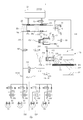
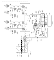
BRIEF DESCRIPTION OF THE DRAWINGS FIG. 1 is a hydraulic circuit diagram showing an uninterrupted state of an electronic brake system according to an embodiment of the present invention; FIG.
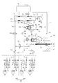
2 is a hydraulic circuit diagram showing a state in which the electronic brake system according to the embodiment of the present invention is normally braked.
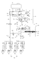
3 is a hydraulic circuit diagram showing a state in which the electronic brake system according to the embodiment of the present invention is normally released.
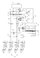
4 is a hydraulic circuit diagram for explaining a state in which the ABS is operated through the electromagnetic brake system according to the embodiment of the present invention.
5 is a hydraulic circuit diagram showing a state in which the electromagnetic brake system according to the embodiment of the present invention operates abnormally.
6 is a hydraulic circuit diagram showing a state in which leakage occurs in the simulator valve.
7 is a hydraulic circuit diagram showing a state in which a leak of a simulator valve is checked in an electronic brake system according to an embodiment of the present invention.
8 and 9 are hydraulic circuit diagrams showing a state in which the drag reduction mode is operated in the electromagnetic brake system according to the embodiment of the present invention.
FIG. 10 is a hydraulic circuit diagram showing an uninterrupted state of an electronic brake system according to another embodiment of the present invention. FIG.
11 is a hydraulic circuit diagram showing a state in which the electronic brake system according to another embodiment of the present invention is normally braked and operated.
12 is a hydraulic circuit diagram showing a state in which the electronic brake system according to another embodiment of the present invention is normally released.
13 is a hydraulic circuit diagram for explaining a state in which the ABS is operated through the electronic brake system according to another embodiment of the present invention.
14 is a hydraulic circuit diagram for explaining a state in which the electronic braking system is operated in a dump mode according to another embodiment of the present invention.
15 is a hydraulic circuit diagram showing a state in which the electromagnetic brake system according to another embodiment of the present invention operates abnormally.
16 is a hydraulic pressure circuit diagram showing a state in which a leakage of a simulator valve is checked in an electronic brake system according to another embodiment of the present invention.
17 and 18 are hydraulic circuit diagrams showing a state in which the drag reduction mode is operated in the electromagnetic brake system according to the embodiment of the present invention.
Hereinafter, embodiments of the present invention will be described in detail with reference to the accompanying drawings. The following embodiments are provided to fully convey the spirit of the present invention to a person having ordinary skill in the art to which the present invention belongs. The present invention is not limited to the embodiments shown herein but may be embodied in other forms. For the sake of clarity, the drawings are not drawn to scale, and the size of the elements may be slightly exaggerated to facilitate understanding.
Fig. 1 is a hydraulic circuit diagram showing the non-synchronized state of the
1, the
The
On the other hand, the
To this end, the
A
The
On the other hand, the
The
1, the
The
On the other hand, the
The
In the meantime,
On the other hand, the
Further, a
The simulating
Since the inside of the
An
The hydraulic
The
The
The
The
On the other hand, the electronic control unit includes the
The driving force of the
The
The
A signal sensed by the
On the other hand, when the
The hydraulic
Alternatively, although not shown in the drawings, the
In addition, it should be understood that the
Next, the
The
The
The first and second
For example, the first
The plurality of
The
And the
The
The first and
The
The
The
A
The first and
Reference numeral " PS11 " is a first hydraulic oil pressure sensor for sensing the hydraulic pressure of the first
Hereinafter, the operation of the
2 is a hydraulic circuit diagram showing a state in which the
Referring to FIG. 2, when the braking by the driver is started, the amount of brake demand of the driver can be sensed through the
The electronic control unit includes a backup hydraulic pressure sensor PS2 provided at the outlet side of the
Specifically, when the driver depresses the
On the other hand, when hydraulic pressure is generated in the hydraulic
The hydraulic pressure discharged from the hydraulic
The pressure generated by the pressing force of the
Next, the case of releasing the braking force in the braking state in the normal operation of the
3, when the pedal force applied to the
On the other hand, the
The
The oil flow in the
The
4 is a hydraulic circuit diagram for explaining a state in which the ABS is actuated through the
FIG. 4 shows a case where only the wheel cylinder is to be braked during the ABS operation, and only the wheels RL and FR of the first
4, the
In addition, only the
The structure for controlling the hydraulic pressure transmitted to the
That is, the
Next, the case where the above-described
5, each
The hydraulic pressure discharged from the
Next, referring to FIGS. 6 and 7, a description will be given of a case where a leak occurs in the
6 is a hydraulic circuit diagram showing a state in which a leak occurs in the
When the
The first and
Accordingly, when the driver depresses the
6, when a leak occurs in the
In this way, when leakage occurs in the
FIG. 7 is a hydraulic circuit diagram showing a state in which an occurrence of leakage of a simulator valve is checked in an
The
The
The
The
And the
The inspection mode is a mode for checking whether a pressure is lost by generating a hydraulic pressure in the hydraulic
Therefore, in the inspection mode, the hydraulic circuit connected to the hydraulic
The
In the inspection mode, after generating the hydraulic pressure in the hydraulic
On the other hand, the inspection mode can be controlled to operate in the case of stopping or when it is determined that there is no acceleration will of the driver. In the inspection mode, since the hydraulic pressure discharged from the hydraulic
For example, the inspection mode can be controlled so as to be operated when a predetermined period of time has elapsed, when the hand brake is in operation, or when the driver is applying a constant braking force.
It is also possible to quickly remove the hydraulic pressure in the
8 and 9 are hydraulic circuit diagrams showing a state in which the drag reduction mode is operated in the
In the drawing, a disk brake is shown as an example of the
The disc brake forms the braking force by the frictional force of the disc brake pad. This frictional force is generated by the brake pads pushed by the hydraulic pressure generated by the operation of the
However, in such a method, a drag phenomenon in which the brake pads and the disk are not completely separated occurs frequently, unnecessary friction shortens the service life of the brake pads, lowers the output, and decreases fuel efficiency.
The
On the other hand, the execution or non-execution of the drag reduction mode can be controlled by the electronic control unit. Alternatively, the driver may operate the separate operation device to execute the drag reduction mode.
8 shows a first drag reduction mode which is a process of operating the hydraulic
In the first drag reduction mode, the
9 shows a second drag reduction mode, which is a process of operating the hydraulic
In the second drag reduction mode, the
Further, in the second drag reduction mode, the
The
Next, the hydraulic control unit 200-1 according to another embodiment of the present invention will be described with reference to FIG. Fig. 10 is a hydraulic circuit diagram showing the non-synchronized state of the electromagnetic brake system 2 according to another embodiment of the present invention.
The hydraulic control unit 200-1 may include a first hydraulic circuit 201-1 and a second hydraulic circuit 202-1, each of which receives hydraulic pressure to control two wheels, and a second hydraulic circuit 202-1. The first hydraulic circuit 201-1 controls the right front wheel FR and the left rear wheel RL and the second hydraulic circuit 202-1 controls the left front wheel FL and the right rear wheel RR Can be controlled. The
The hydraulic control unit 200-1 can receive hydraulic pressure from the hydraulic
The first hydraulic circuit 201-1 includes first and
More specifically, the
The
The
The second hydraulic circuit 201-1 includes third and
More specifically, the
The
The
On the other hand, the opening and closing operations of the first to
The opening and closing operations of the first to
The electronic brake system 2 opens any two inlet valves of the four
The hydraulic pressure through the first and
The first to
The first and
The electromagnetic brake system 2 according to another embodiment of the present invention includes first and second
A
The first
The first and
Reference numeral " PS1 " is a hydraulic pressure sensor for sensing hydraulic pressure of the hydraulic control unit 200-1, and PS2 is a backup hydraulic pressure sensor for measuring the oil pressure of the
Hereinafter, the operation of the electromagnetic brake system 2 according to another embodiment of the present invention will be described in detail.
11 is a hydraulic circuit diagram showing a state in which the electromagnetic brake system 2 according to another embodiment of the present invention is normally braked and operated.
Referring to FIG. 11, when the braking by the driver is started, the amount of braking required by the driver can be sensed through the
The electronic control unit receives the magnitude of the regenerative braking amount through the back-flow passage pressure sensor PS2 provided at the outlet side of the
Specifically, when the driver depresses the
On the other hand, when the hydraulic pressure is supplied from the hydraulic
The hydraulic pressure discharged from the hydraulic
This operation is an operation in a general braking state. When urgent braking is required, both
The pressure generated by the pressing force of the
Next, a description will be made of a case where the braking force is released in the braking state in the normal operation of the electromagnetic brake system 2 according to another embodiment of the present invention. 12 is a hydraulic circuit diagram showing a state in which the electromagnetic brake system 2 according to another embodiment of the present invention is normally released.
12, when the pedal force applied to the
The first to
The
The oil flow in the
The electromagnetic brake system 2 according to the other embodiment of the present invention is also applicable to the
13 is a hydraulic circuit diagram for explaining a state in which the ABS is actuated through the electronic brake system 2 according to another embodiment of the present invention.
FIG. 13 shows a case where only the wheel cylinder is to be braked during the ABS operation, and only the left wheels RL and FL are braked.
13, the
In addition, the first and
That is, the electromagnetic brake system 2 according to another embodiment of the present invention includes first to
14 is a hydraulic circuit diagram for explaining a state in which the electronic braking system 2 is operated in the dump mode according to another embodiment of the present invention.
The electromagnetic brake system 2 according to another embodiment of the present invention can discharge only the braking pressure provided to the
14 shows a state in which the second and
On the other hand, the second and
In this manner, the
Finally, the case where the electronic brake system 2 does not operate normally will be described. 15 is a hydraulic circuit diagram showing a state in which the electromagnetic brake system 2 according to another embodiment of the present invention operates abnormally.
Referring to FIG. 15, when the electronic brake system 2 is not operating normally, the
The hydraulic pressure discharged from the
Next, referring to FIG. 16, a description will be made of a method for checking whether a leak occurs in the
16 is a hydraulic circuit diagram showing a state for checking whether a leak of a simulator valve has occurred in an electronic brake system 2 according to another embodiment of the present invention.
The electronic brake system 2 according to another embodiment of the present invention may further include an
The
The
The
And the
The inspection mode is a mode for checking whether a pressure is lost by generating a hydraulic pressure in the hydraulic
Therefore, in the inspection mode, the hydraulic circuit connected to the hydraulic
The electronic brake system 2 according to another embodiment of the present invention provides hydraulic pressure only to the
In the inspection mode, after generating the hydraulic pressure in the hydraulic
On the other hand, the inspection mode can be controlled to operate in the case of stopping or when it is determined that there is no acceleration will of the driver. In the inspection mode, since the hydraulic pressure generated in the hydraulic
For example, the inspection mode can be controlled so as to be operated when a predetermined period of time has elapsed, when the hand brake is in operation, or when the driver is applying a constant braking force.
In addition, when it is determined that the driver has an intention to accelerate in the test mode, it is possible to quickly remove the hydraulic pressure of the
The electronic brake system 2 according to another embodiment of the present invention can perform a drag reduction mode capable of reducing the occurrence of drag. 17 and 18 are hydraulic circuit diagrams showing a state in which the drag reduction mode is operated in the electromagnetic brake system 2 according to the embodiment of the present invention.
17 shows a first drag reduction mode, which is a process of operating the hydraulic
In the first drag reduction mode, the first and
The figure shows a state in which the second and
18 shows a second drag reduction mode, which is a process of operating the hydraulic
In the second drag reduction mode, the first to
Further, in the second drag reduction mode, the
The
10: Brake pedal 11: Pedal displacement sensor
20: master cylinder 30: reservoir
40: Wheel cylinder 50: Simulation device
54: simulator valve 60: check valve
100: hydraulic pressure supply device 110: pressure supply unit
120: motor 130: power conversion section
200: Hydraulic control unit 201: First hydraulic circuit
202: second hydraulic circuit 211: first hydraulic oil
212: second hydraulic oil passage 221: inlet valve
222: outlet valve 231: first switching valve
232: second switching valve 233: release valve
241: first balance valve 242: second balance valve
251: first backup channel 252: second backup channel
261: first cut valve 262: second cut valve
Claims (13)
A simulation device connected to the master cylinder and having a simulator valve provided in a flow path connecting a simulation chamber in which oil is received and a second reservoir in which oil is stored, to provide a reaction force according to the power of the brake pedal;
A hydraulic pressure supply device for generating a hydraulic pressure by a hydraulic piston operated by an electrical signal output corresponding to the displacement of the brake pedal; And
And a check valve provided in a flow path connecting the first reservoir and the master cylinder,
The simulator valve is arranged to open a flow path connecting the simulation chamber and the first reservoir in a normal mode and to close a flow path connecting the simulation chamber and the first reservoir in an abnormal mode,
Wherein the check valve opens the flow path connecting the first reservoir and the master cylinder in the braking mode and closes the flow path connecting the first reservoir and the master cylinder in the check mode.
The hydraulic pressure supply device generates a hydraulic pressure by using a rotational force of a motor operated by an electrical signal output from the pedal displacement sensor,
A pedal displacement sensor for sensing a displacement of the brake pedal;
A hydraulic pressure control unit for transmitting hydraulic pressure discharged from the hydraulic pressure supply device to a wheel cylinder provided in each wheel; And
And an electronic control unit for controlling the motor and the valves based on the hydraulic pressure information and the displacement information of the brake pedal.
A backup oil channel connecting the master cylinder and the oil pressure control unit, the backup oil channel joining the hydraulic oil channel connected to the hydraulic pressure supply unit,
Further comprising a cut valve provided between a confluence point of the backup channel where the master cylinder and the hydraulic oil path join together to control the flow of hydraulic pressure,
In the normal mode, the cut valve is closed so that a hydraulic pressure discharged from the hydraulic pressure supply device is transmitted to the wheel cylinder,
And in the abnormal mode, the cut valve is opened and a hydraulic pressure discharged from the master cylinder is transmitted to the wheel cylinder.
Further comprising a pressure sensor provided on the backup channel between the master cylinder and the simulation device.
Wherein the pressure sensor is provided between the master cylinder of the backup passage and a flow path branched to the simulation device.
Wherein the electronic control unit is configured to close the simulator valve and the check valve in the test mode and to measure the pressure in the pressure sensor after generating a hydraulic pressure in the hydraulic pressure supply device to determine whether the simulator valve is leaked or not, .
Wherein the check valve is normally open and operates to close upon receipt of a closing signal.
The hydraulic pressure supply device includes a hydraulic pressure supply chamber in which oil is supplied by a hydraulic pressure supply oil passage and is connected to the first reservoir to allow oil to flow from the first reservoir to the hydraulic pressure supply pressure chamber, And a check valve installed in the hydraulic pressure supply oil passage to prevent oil from flowing to the first reservoir.
The hydraulic pressure supply oil passage is branched between the first reservoir and the master cylinder,
Wherein the check valve is provided between a point where the first reservoir and the hydraulic pressure supply oil passage are branched.
A master cylinder having first and second hydraulic ports formed therein and connected to the reservoir and having one or more pistons to discharge oil according to the pressure of the brake pedal;
A pedal displacement sensor for sensing a displacement of the brake pedal;
A first backup oil channel connecting the first hydraulic port and the wheel cylinder;
A second backup oil channel connecting the second hydraulic port and the wheel cylinder;
A first cut valve provided in the first backup passage to control the flow of oil;
A second cut valve provided in the second backup passage to control the flow of oil;
A simulator provided in a flow path branched from the first backup passage and provided with a simulation chamber in which oil is received and a simulator valve provided in a flow path connecting the reservoir and providing a reaction force according to the power of the brake pedal;
A hydraulic pressure supply device for generating a hydraulic pressure using a rotational force of a motor operated by an electrical signal output from the pedal displacement sensor;
An inspection valve provided in a flow path connecting the reservoir and the master cylinder;
A pressure sensor provided between the master cylinder and a flow path branched to the simulation apparatus;
A first hydraulic oil connected to the hydraulic pressure supply device and joined to the first backup hydraulic passage;
A second hydraulic oil connected to the hydraulic pressure supply device and joined to the second backup oil passage;
And a hydraulic circuit connected to the first and second hydraulic oil passages and transmitting the hydraulic pressure discharged from the hydraulic pressure supply device to wheel cylinders provided in the respective wheels, A control unit; And
And an electronic control unit for controlling the motor and the valves based on the hydraulic pressure information and the displacement information of the brake pedal,
Wherein the simulator valve is arranged to open a flow path connecting the simulation chamber and the reservoir in a normal mode and to close a flow path connecting the simulation chamber and the reservoir in an abnormal mode,
Wherein the check valve opens the flow path connecting the reservoir and the master cylinder in the braking mode and closes the flow path connecting the reservoir and the master cylinder in the check mode.
The hydraulic control unit includes:
First to fourth inlet valves respectively provided on the upstream side of the wheel cylinders so as to control the hydraulic pressure flowing into the wheel cylinders provided in the respective wheels;
A first switching valve that controls connection between the hydraulic pressure supply device and the first and second inlet valves, and the hydraulic pressure supply device is provided in a flow path joining the first backup passage; And
Further comprising a second switching valve that controls connection between the hydraulic pressure supply device and the third and fourth inlet valves, and the hydraulic pressure supply device is provided in a flow path joining the second backup passage.
The hydraulic control unit includes:
First to fourth inlet valves respectively provided on the upstream side of the wheel cylinders so as to control the hydraulic pressure flowing into the wheel cylinders provided in the respective wheels; And
A first balance valve for controlling the connection between the first inlet valve and the two wheel cylinders to which the second inlet valve is connected and a second balance valve for controlling the connection between the third inlet valve and the two wheel cylinders to which the fourth inlet valve is connected Further comprising a second balance valve.
The electronic control unit opens the first cut valve and the check valve in the first drag reduction mode to cause the hydraulic pressure provided by the hydraulic pressure supply device to be transmitted to the reservoir and close the check valve in the second drag reduction mode And the hydraulic pressure of the wheel cylinder is transmitted to the hydraulic pressure supply device by the negative pressure provided by the hydraulic pressure supply device.
Priority Applications (1)
| Application Number | Priority Date | Filing Date | Title |
|---|---|---|---|
| KR1020150128865A KR20170031402A (en) | 2015-09-11 | 2015-09-11 | Electric brake system |
Applications Claiming Priority (1)
| Application Number | Priority Date | Filing Date | Title |
|---|---|---|---|
| KR1020150128865A KR20170031402A (en) | 2015-09-11 | 2015-09-11 | Electric brake system |
Publications (1)
| Publication Number | Publication Date |
|---|---|
| KR20170031402A true KR20170031402A (en) | 2017-03-21 |
Family
ID=58502447
Family Applications (1)
| Application Number | Title | Priority Date | Filing Date |
|---|---|---|---|
| KR1020150128865A KR20170031402A (en) | 2015-09-11 | 2015-09-11 | Electric brake system |
Country Status (1)
| Country | Link |
|---|---|
| KR (1) | KR20170031402A (en) |
Cited By (7)
| Publication number | Priority date | Publication date | Assignee | Title |
|---|---|---|---|---|
| KR20180128187A (en) * | 2017-05-23 | 2018-12-03 | 주식회사 만도 | Electric brake system |
| KR20190016269A (en) * | 2017-08-08 | 2019-02-18 | 주식회사 만도 | Electric brake system and method thereof |
| KR20190037599A (en) * | 2017-09-29 | 2019-04-08 | 주식회사 만도 | Electric brake system and control method |
| KR20190127045A (en) * | 2018-05-03 | 2019-11-13 | 주식회사 만도 | Electric brake system and method thereof |
| KR102042608B1 (en) * | 2018-09-06 | 2019-11-27 | 주식회사 만도 | Electric brake system |
| KR20200007062A (en) * | 2018-02-22 | 2020-01-21 | 주식회사 만도 | Electric brake system and method thereof |
| US11066056B2 (en) * | 2017-12-11 | 2021-07-20 | Hyundai Motor Company | Control system of regenerative braking of hybrid vehicle and control method for the same |
Citations (1)
| Publication number | Priority date | Publication date | Assignee | Title |
|---|---|---|---|---|
| EP2520473A1 (en) | 2010-02-26 | 2012-11-07 | Honda Motor Co., Ltd. | Vehicle brake device and vehicle brake device control method |
-
2015
- 2015-09-11 KR KR1020150128865A patent/KR20170031402A/en unknown
Patent Citations (1)
| Publication number | Priority date | Publication date | Assignee | Title |
|---|---|---|---|---|
| EP2520473A1 (en) | 2010-02-26 | 2012-11-07 | Honda Motor Co., Ltd. | Vehicle brake device and vehicle brake device control method |
Cited By (9)
| Publication number | Priority date | Publication date | Assignee | Title |
|---|---|---|---|---|
| KR20180128187A (en) * | 2017-05-23 | 2018-12-03 | 주식회사 만도 | Electric brake system |
| KR20190016269A (en) * | 2017-08-08 | 2019-02-18 | 주식회사 만도 | Electric brake system and method thereof |
| KR20190037599A (en) * | 2017-09-29 | 2019-04-08 | 주식회사 만도 | Electric brake system and control method |
| US11084473B2 (en) | 2017-09-29 | 2021-08-10 | Mando Corporation | Electric brake system and control method thereof |
| US11066056B2 (en) * | 2017-12-11 | 2021-07-20 | Hyundai Motor Company | Control system of regenerative braking of hybrid vehicle and control method for the same |
| KR20200007062A (en) * | 2018-02-22 | 2020-01-21 | 주식회사 만도 | Electric brake system and method thereof |
| KR20190127045A (en) * | 2018-05-03 | 2019-11-13 | 주식회사 만도 | Electric brake system and method thereof |
| KR102042608B1 (en) * | 2018-09-06 | 2019-11-27 | 주식회사 만도 | Electric brake system |
| US10919509B2 (en) | 2018-09-06 | 2021-02-16 | Mando Corporation | Electronic brake system |
Similar Documents
| Publication | Publication Date | Title |
|---|---|---|
| KR20170031400A (en) | Electric brake system | |
| KR20170065827A (en) | Electric brake system and method for leak check of the same | |
| KR102495106B1 (en) | Electric brake system | |
| KR102435304B1 (en) | Electric brake system | |
| KR102475862B1 (en) | Electric brake system | |
| KR102473927B1 (en) | Diagnosis method of Electric brake system | |
| KR102461255B1 (en) | Electric brake system | |
| KR102424997B1 (en) | Electric brake system | |
| KR20170059042A (en) | Electric brake system | |
| KR20170031402A (en) | Electric brake system | |
| KR20180045556A (en) | Electric brake system | |
| CN108928333B (en) | Electronic brake system and control method thereof | |
| KR20190034931A (en) | Electric brake system | |
| KR20170059039A (en) | Electric brake system | |
| KR20170130995A (en) | Electric brake system | |
| KR20170031396A (en) | Electric brake system | |
| KR20180109179A (en) | Electric brake system | |
| KR20180045568A (en) | Electric brake system | |
| CN108928334B (en) | Electronic brake system | |
| KR20170031405A (en) | Electric brake system | |
| KR20170031397A (en) | Electric brake system | |
| KR20150118211A (en) | Electric brake system | |
| KR20180128183A (en) | Electric brake system | |
| KR20180128187A (en) | Electric brake system | |
| KR20190023827A (en) | Electric brake system |