Hereinafter, embodiments of the present invention will be described in detail with reference to the accompanying drawings, wherein like reference numerals are used to designate identical or similar elements, and redundant description thereof will be omitted. The suffix "module" and " part "for the components used in the following description are given or mixed in consideration of ease of specification, and do not have their own meaning or role. In the following description of the embodiments of the present invention, a detailed description of related arts will be omitted when it is determined that the gist of the embodiments disclosed herein may be blurred. It is to be understood that both the foregoing general description and the following detailed description are exemplary and explanatory and are intended to provide further explanation of the invention as claimed. , ≪ / RTI > equivalents, and alternatives.
Terms including ordinals, such as first, second, etc., may be used to describe various elements, but the elements are not limited to these terms. The terms are used only for the purpose of distinguishing one component from another.
It is to be understood that when an element is referred to as being "connected" or "connected" to another element, it may be directly connected or connected to the other element, . On the other hand, when an element is referred to as being "directly connected" or "directly connected" to another element, it should be understood that there are no other elements in between.
The singular expressions include plural expressions unless the context clearly dictates otherwise.
In the present application, the terms "comprises", "having", and the like are used to specify that a feature, a number, a step, an operation, an element, a component, But do not preclude the presence or addition of one or more other features, integers, steps, operations, elements, components, or combinations thereof.
1 shows a block diagram of a vehicle 1 according to an embodiment of the present invention.
1, a vehicle 1 includes a communication unit 110, an input unit 120, a memory 130, an output unit 140, a vehicle driving unit 150, a sensing unit 160, a control unit 170, Unit 180, and a power source unit 190. [
The communication unit 110 may include one or more modules that enable wireless communication between the vehicle 1 and an external device (e.g., portable terminal, external server, other vehicle). In addition, the communication unit 110 may include one or more modules for connecting the vehicle 1 to one or more networks.
The communication unit 110 may include a broadcast receiving module 111, a wireless Internet module 112, a local area communication module 113, a location information module 114, and an optical communication module 115.
The broadcast receiving module 111 receives broadcast signals or broadcast-related information from an external broadcast management server through a broadcast channel. Here, the broadcast includes a radio broadcast or a TV broadcast.
The wireless Internet module 112 refers to a module for wireless Internet access and may be built in or externally mounted on the vehicle 1. [ The wireless Internet module 112 is configured to transmit and receive wireless signals in a communication network according to wireless Internet technologies.
Wireless Internet technologies include, for example, WLAN (Wireless LAN), Wi-Fi (Wireless Fidelity), Wi-Fi (Wireless Fidelity) Direct, DLNA, WiBro Interoperability for Microwave Access, High Speed Downlink Packet Access (HSDPA), High Speed Uplink Packet Access (HSUPA), Long Term Evolution (LTE) and Long Term Evolution-Advanced (LTE-A) 112 transmit and receive data according to at least one wireless Internet technology, including Internet technologies not listed above. For example, the wireless Internet module 112 may exchange data wirelessly with an external server. The wireless Internet module 112 can receive weather information and road traffic situation information (for example, TPEG (Transport Protocol Expert Group)) from an external server.
The short-range communication module 113 is for short-range communication, and includes Bluetooth ™, Radio Frequency Identification (RFID), Infrared Data Association (IrDA), Ultra Wideband (UWB) (Near Field Communication), Wi-Fi (Wireless-Fidelity), Wi-Fi Direct, and Wireless USB (Wireless Universal Serial Bus) technology.
The short-range communication module 113 may form short-range wireless communication networks to perform short-range communication between the vehicle 1 and at least one external device. For example, the short-range communication module 113 can wirelessly exchange data with the occupant's portable terminal. The short-range communication module 113 can receive weather information and road traffic situation information (for example, TPEG (Transport Protocol Expert Group)) from a portable terminal or an external server. For example, when the user has boarded the vehicle 1, the portable terminal of the user and the vehicle 1 can perform the pairing with each other automatically or by the execution of the user's application.
The position information module 114 is a module for obtaining the position of the vehicle 1, and a representative example thereof is a Global Positioning System (GPS) module. For example, when the vehicle utilizes a GPS module, it can acquire the position of the vehicle using a signal sent from the GPS satellite.
The optical communication module 115 may include a light emitting portion and a light receiving portion.
The light receiving section can convert the light signal into an electric signal and receive the information. The light receiving unit may include a photodiode (PD) for receiving light. Photodiodes can convert light into electrical signals. For example, the light receiving section can receive information of the front vehicle through light emitted from the light source included in the front vehicle.
The light emitting unit may include at least one light emitting element for converting an electric signal into an optical signal. Here, the light emitting element is preferably an LED (Light Emitting Diode). The optical transmitter converts the electrical signal into an optical signal and transmits it to the outside. For example, the optical transmitter can emit the optical signal to the outside through the blinking of the light emitting element corresponding to the predetermined frequency. According to an embodiment, the light emitting portion may include a plurality of light emitting element arrays. According to the embodiment, the light emitting portion can be integrated with the lamp provided in the vehicle 1. [ For example, the light emitting portion may be at least one of a headlight, a tail light, a brake light, a turn signal lamp, and a car light. For example, the optical communication module 115 can exchange data with other vehicles through optical communication.
The input unit 120 may include a driving operation unit 121, a microphone 123, and a user input unit 124.
The driving operation means 121 receives a user input for driving the vehicle 1. [ The driving operation means 121 may include a steering input means 121a, a shift input means 121b, an acceleration input means 121c and a brake input means 121d.
The steering input means 121a receives a forward direction input of the vehicle 1 from the user. The steering input means 121a may include a steering wheel. According to the embodiment, the steering input means 121a may be formed of a touch screen, a touch pad, or a button.
The shift input means 121b receives inputs of parking (P), forward (D), neutral (N) and reverse (R) of the vehicle 1 from the user. The shift input means 121b is preferably formed in a lever shape. According to an embodiment, the shift input means 121b may be formed of a touch screen, a touch pad, or a button.
The acceleration input means 121c receives an input for acceleration of the vehicle 1 from the user. The brake input means 121d receives an input for decelerating the vehicle 1 from the user. The acceleration input means 121c and the brake input means 121d are preferably formed in the form of a pedal. According to the embodiment, the acceleration input means 121c or the brake input means 121d may be formed of a touch screen, a touch pad, or a button.
The microphone 123 can process an external acoustic signal into electrical data. The processed data can be variously utilized depending on the function being performed in the vehicle 1. [ The microphone 123 can convert the voice command of the user into electrical data. The converted electrical data may be transmitted to the control unit 170.
The camera 122 or the microphone 123 may be a component included in the sensing unit 160 and not a component included in the input unit 120. [
The user input unit 124 is for receiving information from a user. When information is inputted through the user input unit 124, the control unit 170 can control the operation of the vehicle 1 so as to correspond to the input information. The user input unit 124 may include a touch input means or a mechanical input means. According to an embodiment, the user input 124 may be located in one area of the steering wheel. In this case, the user can operate the user input unit 124 with his / her finger while holding the steering wheel.
The input unit 120 may include a plurality of buttons or a touch sensor. It is also possible to perform various input operations through a plurality of buttons or touch sensors.
The sensing unit 160 senses a signal relating to the running of the vehicle 1 or the like. To this end, the sensing unit 160 may include a sensor, a steering sensor, a speed sensor, a tilt sensor, a weight sensor, a heading sensor, a yaw sensor, a gyro sensor, Position sensor, vehicle forward / backward sensor, battery sensor, fuel sensor, tire sensor, steering sensor by steering wheel rotation, vehicle internal temperature sensor, internal humidity sensor, ultrasonic sensor, infrared sensor, radar, . ≪ / RTI >
Accordingly, the sensing unit 160 can sense the vehicle collision information, the vehicle direction information, the vehicle position information (GPS information), the vehicle angle information, the vehicle speed information, the vehicle acceleration information, the vehicle tilt information, Fuel information, tire information, vehicle lamp information, vehicle interior temperature information, vehicle interior humidity information, steering wheel rotation angle, and the like. The control unit 170 also controls the acceleration and deceleration of the vehicle 1 based on the external environment information obtained by at least one of the camera, the ultrasonic sensor, the infrared sensor, the radar, A control signal for changing direction, etc. can be generated. Here, the external environment information may be information related to various objects located within a predetermined distance range from the vehicle 1 while driving. For example, the external environment information may include information on the number of obstacles located within a distance of 100 m from the vehicle 1, the distance to the obstacle, the size of the obstacle, the type of the obstacle, and the like.
The sensing unit 160 may further include an accelerator pedal sensor, a pressure sensor, an engine speed sensor, an air flow sensor AFS, an intake air temperature sensor ATS, a water temperature sensor WTS, A sensor (TPS), a TDC sensor, a crank angle sensor (CAS), and the like.
The sensing unit 160 may include a biometric information sensing unit. The biometric information sensing unit senses and acquires the biometric information of the passenger. The biometric information may include fingerprint information, iris-scan information, retina-scan information, hand geo-metry information, facial recognition information, Voice recognition information. The biometric information sensing unit may include a sensor that senses the passenger's biometric information. Here, the camera 162 and the microphone 123 can operate as sensors. The biometric information sensing unit can acquire the hand shape information and the face recognition information through the camera 162. [
The sensing unit 160 may include at least one camera 161 for photographing the outside of the vehicle 2. [ For example, the sensing unit 160 may include a plurality of cameras 161 disposed at different positions of the vehicle exterior. The camera 161 may include an image sensor and an image processing module. The camera 161 can process still images or moving images obtained by an image sensor (e.g., CMOS or CCD). The image processing module may process the still image or the moving image obtained through the image sensor, extract necessary information, and transmit the extracted information to the control unit 170.
The sensing unit 160 may include at least one camera 162 for photographing the interior of the vehicle 1. [ For example, the camera 162 may generate an image including the occupant of the vehicle 1, and then provide the image to the control unit 170. [
The cameras 161 and 162 may include an image sensor (e.g., CMOS or CCD) and an image processing module. In addition, the cameras 161 and 162 can process still images or moving images obtained by the image sensor. The image processing module can process the still image or moving image obtained through the image sensor. In addition, the cameras 161 and 162 can acquire images including at least one of traffic lights, traffic signs, pedestrians, other vehicles, and road surfaces.
The output unit 140 may include a display unit 141, an acoustic output unit 142, a haptic output unit 143, and an optical output unit 144, for outputting information processed by the control unit 170 have.
The display unit 141 outputs an image for guiding various information related to the vehicle 1. [
In one embodiment, the display unit 141 may display information processed by the control unit 170. [ For example, the display unit 141 can display vehicle-related information. Here, the vehicle-related information may include vehicle control information for direct control of the vehicle 1, or vehicle driving assistance information for a driving guide to the user of the vehicle 1. [ Further, the vehicle-related information may include vehicle state information indicating the current state of the vehicle or vehicle driving information related to the driving of the vehicle.
The display unit 141 may be a liquid crystal display (LCD), a thin film transistor-liquid crystal display (TFT LCD), an organic light-emitting diode (OLED) display, a 3D display, and an e-ink display.
The display unit 141 may have a mutual layer structure with the touch sensor or may be integrally formed to realize a touch screen. Such a touch screen may function as a user input 124 to provide an input interface between the vehicle 1 and the user and at the same time provide an output interface between the vehicle 1 and the user. In this case, the display unit 141 may include a touch sensor that senses a touch with respect to the display unit 141 so as to receive a control command by a touch method. When a touch is made to the display unit 141, the touch sensor senses the touch, and the control unit 170 generates a control command corresponding to the touch based on the touch. The content input by the touch method may be a letter or a number, an instruction in various modes, a menu item which can be designated, and the like.
Meanwhile, the display unit 141 may include a cluster for outputting vehicle status information or vehicle driving information while the driver is driving. Clusters can be located in one area of the dashboard. In this case, the driver can confirm the information displayed in the cluster while keeping the gaze ahead of the vehicle.
Meanwhile, according to the embodiment, the display unit 141 may include a Head Up Display (HUD). The HUD can output information through a windshield.
The sound output unit 142 converts an electric signal from the control unit 170 into an audio signal and outputs the audio signal. For this purpose, the sound output unit 142 may include a speaker or the like. It is also possible that the sound output unit 142 outputs a sound corresponding to the operation of the user input unit 124. [
The haptic output unit 143 generates a tactile output. For example, the haptic output section 143 may vibrate the steering wheel, the seat belt, and the seat so that the user can operate to recognize the output.
The optical output unit 154 is configured to output light for notifying the occurrence of an event. Examples of events include user input reception via a touch sensor, over speed limit, fuel shortage, destination arrival, music playback, and the like. The light output section 154 may be disposed at a position in the interior of the vehicle 1. [ For example, the light output section 154 may be disposed on the steering wheel. The controller 170 may control the light output unit 154 to start or stop the output of light when the event confirmation of the user is detected.
The vehicle driving unit 150 can control the operation of various devices of the vehicle. The vehicle driving unit 150 includes a power source driving unit 151, a steering driving unit 152, a brake driving unit 153, a lamp driving unit 154, an air conditioning driving unit 155, a window driving unit 156, a seat driving unit 157, A driving unit 158, and a wiper driving unit 159. [0035]
The power source drive unit 151 may perform electronic control of the power source in the vehicle 1. [ The power source drive section 151 may include an accelerator for increasing the speed of the vehicle 1 and a decelerator for decreasing the speed of the vehicle 1. [ Cruise control can be implemented by the accelerator and the decelerator.
For example, when the fossil fuel-based engine (not shown) is a power source, the power source drive unit 151 can perform electronic control of the engine. Thus, the output torque of the engine and the like can be controlled. When the power source drive unit 151 is an engine, the speed of the vehicle can be limited by limiting the engine output torque under the control of the control unit 170. [
In another example, when the electric motor (not shown) is a power source, the power source drive unit 151 can perform control on the motor. Thus, the rotation speed, torque, etc. of the motor can be controlled.
The steering driver 152 may include a steering apparatus. Thus, the steering driver 152 can perform electronic control of the steering apparatus in the vehicle 1. [ For example, the steering driver 152 may be provided with a steering torque sensor, a steering angle sensor, and a steering motor, and the steering torque applied by the driver to the steering wheel may be sensed by the steering torque sensor. The steering driver 152 can control the steering force and the steering angle by changing the magnitude and direction of the current applied to the steering motor based on the speed of the vehicle 1 and the steering torque. In addition, the steering driver 152 can determine whether the running direction of the vehicle 1 is properly adjusted based on the steering angle information obtained by the steering angle sensor. Thereby, the running direction of the vehicle can be changed. In addition, the steering driver 152 reduces the weight of the steering wheel by increasing the steering force of the steering motor when the vehicle 1 travels at low speed, and reduces the steering force of the steering motor when the vehicle 1 travels at high speed, The weight can be increased. When the autonomous running function of the vehicle 1 is executed, the steering drive unit 152 may be configured so that even when the driver operates the steering wheel (e.g., a situation where the steering torque is not detected) It is also possible to control the steering motor to generate appropriate steering force based on the sensing signal or the control signal provided by the control unit 170. [
The brake driver 153 can perform electronic control of a brake apparatus (not shown) in the vehicle 1. [ For example, it is possible to reduce the speed of the vehicle 1 by controlling the operation of the brakes disposed on the wheels. As another example, it is possible to adjust the traveling direction of the vehicle 1 to the left or right by differently operating the brakes respectively disposed on the left wheel and the right wheel.
The lamp driving unit 154 may control the turn-on / turn-off of at least one or more lamps disposed inside or outside the vehicle. The lamp driver 154 may include a lighting device. Further, the lamp driving unit 154 can control intensity, direction, etc. of light output from each of the lamps included in the lighting apparatus. For example, it is possible to perform control for a direction indicating lamp, a head lamp, a brake lamp, and the like.
The air conditioning driving unit 155 may perform electronic control on an air conditioner (not shown) in the vehicle 1. [ For example, the air conditioning driving unit 155 can control the air conditioner to operate so that the cool air is supplied to the inside of the vehicle when the inside temperature of the vehicle is high or there is a user input for commanding cooling. For example, when the temperature inside the vehicle is low or there is a user input for commanding heating, the air conditioning driving unit 155 operates the air conditioner so that the warmth (which may be provided from the engine) To be supplied.
The window driving unit 156 may perform electronic control of the window apparatus in the vehicle 1. [ For example, it is possible to control the opening or closing of the side of the vehicle with respect to the left and right windows.
The seat driving unit 157 electrometrically adjusts the position or posture of at least one seat (e.g., driver's seat, driver's seat) provided on the vehicle 1. [ Specifically, the seat driving unit 167 can move the seat vertically and horizontally or adjust the angle of the backrest by using an electric pump or an electric motor combined with the seat. The sheet to be electrically controlled in accordance with the driving of the seat driving unit 167 may be called a power seat.
The sunroof driving unit 158 may perform electronic control of a sunroof apparatus (not shown) in the vehicle 1. [ For example, the opening or closing of the sunroof can be controlled.
The wiper driving unit 159 can control the wiper 13 provided in the vehicle 1. [ For example, the wiper driving unit 159 may be configured to drive the wiper 13 via the user input unit 124. When the wiper 13 is driven by the user, Control can be performed. For example, the wiper driving unit 159 may determine the amount or intensity of the rainwater based on the sensing signal of the rain sensor included in the sensing unit 160, and automatically drive the wiper without user input .
Meanwhile, the vehicle driving unit 150 may further include a suspension driving unit (not shown). The suspension driving unit may perform electronic control of a suspension apparatus (not shown) in the vehicle 1. [ For example, when there is a curvature on the road surface, it is possible to control the suspension device so as to reduce the vibration of the vehicle 1. [
The memory 130 is electrically connected to the controller 170. The memory 170 may store basic data for the unit, control data for controlling the operation of the unit, and input / output data. The memory 190 may be, in hardware, various storage devices such as ROM, RAM, EPROM, flash drive, hard drive, and the like. The memory 130 may store various data for operation of the entire vehicle 1, such as a program for processing or controlling the controller 170. [
The interface unit 180 may serve as a pathway to various kinds of external devices connected to the vehicle 1. [ For example, the interface unit 180 may include a port connectable to the portable terminal, and may be connected to the portable terminal through the port. In this case, the interface unit 180 can exchange data with the portable terminal.
The interface unit 180 may receive the turn signal information. Here, the turn signal information may be a turn-on signal of the turn signal lamp for the left turn or the turn right turn inputted by the user. When the left or right turn signal turn-on input is received through the user input portion (724 in Fig. 6) of the vehicle, the interface portion 180 can receive left turn signal information or right turn signal information.
The interface unit 180 may receive vehicle speed information, rotation angle information of the steering wheel, or gear shift information. The interface unit 180 may receive the sensed vehicle speed information, the steering wheel rotation angle information, or the gear shift information through the sensing unit 160 of the vehicle. Alternatively, the interface unit 180 may receive the vehicle speed information, the steering wheel rotation angle information, or the gear shift information from the control unit 170 of the vehicle. Here, the gear shift information may be information on which state the shift lever of the vehicle is in. For example, the gear shift information may be information on which state the shift lever is in the parking (P), reverse (R), neutral (N), running (D) .
The interface unit 180 may receive a user input received via a user input 124 of the vehicle 1. [ The interface unit 180 may receive user input from the input unit 120 of the vehicle 1 or via the control unit 170. [
The interface unit 180 can receive information obtained from an external device. For example, when the traffic light change information is received from the external server through the communication unit 110 of the vehicle 1, the interface unit 180 can receive the traffic light change information from the control unit 170. [
The control unit 170 can control the overall operation of each unit in the vehicle 1. [ The control unit 170 may be referred to as an ECU (Electronic Control Unit).
The control unit 170 may be implemented in hardware as application specific integrated circuits (ASICs), digital signal processors (DSPs), digital signal processing devices (DSPDs), programmable logic devices (PLDs), field programmable gate arrays (FPGAs) ), Controllers, micro-controllers, microprocessors, and other electronic units for performing other functions.
The power supply unit 190 can supply power necessary for the operation of each component under the control of the controller 170. [ In particular, the power supply unit 170 can receive power from a battery (not shown) or the like inside the vehicle.
The AVN (Audio Video Navigation) device 400 can exchange data with the control unit 170. [ The control unit 170 may receive navigation information from the AVN apparatus or a separate navigation apparatus (not shown). Here, the navigation information may include set destination information, route information according to the destination, map information about the vehicle driving, or vehicle location information.
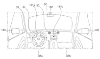
Fig. 2 shows an exemplary appearance of the vehicle 1 shown in Fig. 1, and Fig. 3 shows an exemplary interior view of the vehicle 1 shown in Fig.
2 (a) and 2 (b), the vehicle 1 may include a wheel 11, a window 12, a side mirror 14, a loop 16, and the like.
The wheel 11 includes the front wheels 11A and 11B disposed on the front left and right of the vehicle 1 and the rear wheels 11C and 11D disposed on the rear left and right sides to bear the load of the vehicle 1. [
The window 12 may include a front window 12A, a side window 12B, and a rear window 12C.
An external background is illuminated on the side mirrors 14 so that the user can check the situation behind the left and right sides of the vehicle 1. [ As shown, the side mirrors 14 may include a first side mirror 14A mounted outside the driver's seat of the vehicle 1 and a second side mirror 14B mounted outside the front passenger's seat.
At least one camera 161 for photographing the periphery of the vehicle 1 may be disposed on the exterior of the vehicle 1. [
Specifically, the camera 161 can generate images for the front, rear, left room, or right room of the vehicle 1. For example, the camera 161 may include a first camera 161a, a second camera 161b, a first camera 161c, and a fourth camera 161d. The first camera 161a generates a forward image, the second camera 161b generates a left image, the third camera 161b generates a right image, and the fourth camera 161d generates a rear image Can be generated. The camera 161 may generate an image for a blind spot that is not visible to the user.
2, the vehicle 1 is shown as a four-wheel vehicle, but the present invention is not limited thereto.
3, the interior of the vehicle 1 is provided with a steering wheel 31, a rear view mirror 32, a tuyer 33, a dashboard 34, a plurality of sheets 35a and 35b, a camera 162 And a display unit 141 may be disposed. In one embodiment, the display unit 141 may include a first display 141a and a second display 141b. For example, the first display 141a may be an LCD display window located in one area of the instrument panel 34 of the vehicle 1, as shown. Also, the second display 141b may be a multimedia display located in one area of the center pager of the vehicle 1. [ The second display 141b may be operatively associated with the multimedia device of the vehicle 1. [ The second display 141b may output an image corresponding to a radio, a DMB, a music, a movie, etc. reproduced by the multimedia device. Also, the second display 141b can output the route guidance image provided by the multimedia device.
On the other hand, some of the components shown in Figs. 1 to 3 may not be essential for realizing the vehicle 1. Fig. Thus, the vehicle 1 described herein may have more or fewer components than those listed above.
4 shows an exemplary process (S400) executed by the vehicle 1 according to an embodiment of the present invention.
Referring to Fig. 4, in step S410, the vehicle 1 can sense the rotation angle of the steering wheel 31. Fig. In one embodiment, the rotation axis of the steering wheel 31 may be coupled with a rotation angle sensor. The rotation angle sensor may provide the control unit 170 with a signal corresponding to the angle at which the steering wheel 31 is rotated clockwise or counterclockwise. The controller 170 may sense the rotation angle of the steering wheel 31 based on a signal provided from the rotation angle sensor.
In step S420, the vehicle 1 can judge whether the rotational angle of the detected steering wheel 31 is equal to or less than the reference angle. In one embodiment, the reference angle may be stored in the memory 130, and the controller 170 may obtain a reference angle from the memory 130 and compare it to the current rotational angle of the steering wheel 31. [ For example, when the reference angle is 30 degrees, if the steering wheel 31 is rotated by 20 degrees in the clockwise direction, the controller 170 determines that the rotation angle of the steering wheel 31 is smaller than the reference angle have. On the other hand, if the steering wheel 31 is rotated by 40 degrees in the counterclockwise direction, the controller 170 may determine that the rotation angle of the steering wheel 31 is larger than the reference angle. If it is determined that the detected rotation angle of the steering wheel 31 is equal to or less than the reference angle, the controller 170 may perform step S430. On the other hand, when it is determined that the rotation angle of the steering wheel 31 is larger than the reference angle, the controller 170 repeatedly performs step S410 until the rotation angle of the steering wheel 31 becomes equal to or smaller than the reference angle can do.
In step S430, the vehicle 1 can activate the touch sensor (refer to reference numeral 510 in Fig. 5) disposed on the steering wheel 31. Fig. Specifically, the controller 170 can activate the touch sensor disposed on the steering wheel 31 only when the rotational angle of the steering wheel 31 is equal to or less than the reference angle. The touch sensor may be disposed at a rim of the steering wheel 31. [ Accordingly, a user (e.g., a driver) may be able to apply various user inputs to the touch sensor, without taking his / her hands off the steering wheel 31, while the vehicle 1 is traveling.
Meanwhile, the touch sensor disposed on the steering wheel 31 may include a plurality of sensing areas. Any one sensing region included in the plurality of sensing regions may be allocated to a position that does not overlap with the other sensing region. In one embodiment, the controller 170 may adjust the number of the plurality of sensing areas included in the touch sensor. For example, the control unit 170 can designate only two different areas of the touch sensor as the sensing area based on the voice command received through the microphone 123. In this case, the remaining area of the touch sensor is inactivated, and can be in a state of not responding to the touch of the user. Further, each of the plurality of sensing regions may have the same or different shapes or sizes.
In step S440, the vehicle 1 may receive user input for at least one sensing area included in the touch sensor. Specifically, the control unit 170 may receive user input through at least one sensing area that is touched by a user among a plurality of sensing areas included in the touch sensor.
In one embodiment, the user input may correspond to any one sensing region included in the touch sensor. For example, when three sensing areas are included in the touch sensor, when the user touches the first sensing area and then touches the second sensing area, the controller 170 displays the user input corresponding to the first sensing area first touched Or only the user input corresponding to the second touching area lastly touched can be received. In one embodiment, the user input may correspond to two or more sensing regions included in the touch sensor. For example, when four sensing areas are included in the touch sensor, the controller 170 may receive user inputs simultaneously or sequentially applied to two or more sensing areas of the four sensing areas.
In one embodiment, the user inputs that can be received through each sensing area included in the touch sensor include, for example, single tapping, double tapping, long tapping, swiping, and gripping.
In step S450, the vehicle 1 may execute a function corresponding to the user input received in step S440 among a plurality of functions executable on the vehicle 1. [ The plurality of functions that can be performed in the vehicle 1 include at least one of a wiper, a light, a direction indicator, a window, a sunroof, a seat, a speaker, a door, a mirror, a camera, an air conditioner, Lt; / RTI >
For example, functions related to wipers can include wiper turn-on / turn-off functions, wiper speed control, washer fluid ejection function, and switching between windshield wipers and rear windshield wipers. Lighting-related functions may include a headlight turn-on / turn-off function, a taillight turn-on / turn-off function, an illumination-based auto turn-on / turn-off function, an indoor light turn-on / turn- Functions related to the turn signal lamp may include a left turn signal turn-on / turn-off function, a right turn signal turn-on / turn-off function, and the like. Windows-related functions may include a window locking function, a window opening function, and a window closing function. Functions related to the sunroof may include opening the sunroof function, closing the head close function, and the like. The functions related to the seat may include the function of adjusting the driver's seat / backrest adjustment, the function of shifting the driver / supporter up and down, and the function of moving the driver / assistant back and forth. Speaker-related functions may include a speaker turn-on / turn-off function, and a speaker volume control function. Door related functions may include automatic door locking. Mirror-related functions may include a mirror angle adjustment function. The camera-related functions may include a camera turn-on / turn-off function, a shooting image storage function, and the like. Functions related to the air conditioner may include air conditioner or heater turn-on / turn-off function, temperature control function, air volume control function, and indoor / outdoor air selection function. The acceleration-related functions may include an acceleration function. The function related to the deceleration device may include a deceleration function. Functions related to both the accelerator and the decelerator may include a constant cruise control function. Functions associated with the multimedia device may include the ability to play / stop any multimedia (e.g., movie, music, electronic map), switch between multimedia, and the like. On the other hand, it is apparent to those skilled in the art that a plurality of functions executable in the vehicle 1 are not limited to the scope of the present invention described above, and that various other functions may be further included.
In one embodiment, each of the plurality of sensing regions included in the touch sensor may be associated with at least one function. When a certain sensing area is interlocked with two or more functions, the control unit 170 can selectively execute any one of two or more functions linked to each other based on a user input. For example, when a first function and a second function are interlocked in a sensing region, a first function is mapped to respond to sweeping, and a second function is mapped to respond to a single tapping, 170 executes a first function when a user input corresponding to sweeping is received in a corresponding sensing area and executes a second function when a user input corresponding to a single tapping is received in the sensing area, When a user input that does not correspond to single tapping is received, both the first function and the second function may not be executed. In another example, when the sweeping of the first length is received in the specific sensing area among the plurality of sensing areas, the controller 170 performs a function mapped to the sweep of the first length, , The function mapped to the sweeping of the second length can be executed. Accordingly, it is possible to provide various functions to the user even if the sensing area in which the user input is received is the same.
In one embodiment, at least one of a plurality of functions executable in the vehicle 1 may be mapped together in two or more sensing regions included in the touch sensor. For example, a specific function (e.g., a sunroof close function) can be executed by the control unit 170 only when two or more sensing areas included in the touch sensor are touched simultaneously or sequentially within a time limit. For example, when the user applies a sweeping method user input that starts in one sensing area and ends in another sensing area, the controller 170 can execute a specific function in response to a user input of a sweeping method.
In one embodiment, the function corresponding to the user input among the plurality of functions executable in the vehicle 1 may include a function of setting a secret pattern. The secret pattern may be a pattern required for switching between the non-travel mode and the travel mode of the vehicle 1. [ Here, the non-travelable mode may be a mode in which running of the vehicle 1 is disabled. For example, in the non-travelable mode, the controller 170 may block the energy supplied to the engine or operate the braking device to prevent the vehicle 1 from moving. Alternatively, the control unit 170 may disable the ignition switch so that the ignition of the vehicle 1 is not turned on in the non-travelable mode. Alternatively, the control unit 170 may lock at least one of the steering wheel 31 and the gear in the non-travelable mode. Such a non-running mode may be a mode in which the vehicle 1 is automatically entered when the starting of the vehicle 1 is turned off. That is, when the vehicle 1 is moving, the control unit 170 can stop the traveling to the non-travel mode.
Next, the travelable mode may be a mode that allows the vehicle 1 to travel. For example, by activating the ignition switch, the lock of the ignition switch can be released. Accordingly, the user can turn on the vehicle 1 at startup. In a state where the secret pattern setting function is executed, the controller 170 may set a pattern corresponding to a user input that simultaneously or sequentially touches two or more of the plurality of sensing areas included in the touch sensor as a secret pattern.
In one embodiment, the control unit 170 can perform the function of controlling the switching between the non-travel mode and the travel mode of the vehicle 1 when the user input coincides with the predetermined secret pattern. The user input received through the touch sensor disposed on the steering wheel 31 should coincide with a predetermined secret pattern in order to switch the vehicle 1 with the secret pattern set from the non-travel mode to the travel mode. For example, in the non-travelable mode, when the touch order and the method for each sensing area corresponding to the user input are not the same as the order and manner of the predetermined secret pattern, the controller 170 can keep the travel disabled mode. Thus, even if the driver is located in the vehicle 1 with the key (e.g., a smart key), the vehicle 1 can be driven only when a correct secret pattern is input, Theft can be prevented in advance.
In one embodiment, the control unit 170 can execute the function of storing the state information of the vehicle 1 at the time when the user input is received, based on the user input. For example, the state information of the vehicle 1 at a specific point in time can be stored in the memory 130. [ Further, the control unit 170 can execute the function of setting the stored state information of the vehicle 1 in the vehicle 1 based on the user's input. Here, the state information of the vehicle 1 is information indicating the position of the seat (e.g., the up / down / forward / backward position, the backrest angle), the position of the mirror (e.g., the side mirrors and the rear view mirrors) (E.g., temperature, air volume, wind direction), a previously retrieved destination list (e.g., a destination retrieved during the last week), and a previously played multimedia list have. According to this, the user can set the state information stored in the past to the vehicle 1 equally. For example, even when the backrest angle of the driver's seat adjusted for the first user is changed by the second user, the first user applies the user input corresponding to the function of setting the stored state information to the vehicle 1, To the state before the back angle of the second user is changed by the second user.
In one embodiment, the control unit 170 can execute a function corresponding to the user input only when at least one of the pressure and the length of the user input satisfies a predetermined condition. For example, the control unit 170 may not perform any function when the pressure of the user input is lower than the reference pressure. Similarly, the controller 170 may not perform any function if the length of the user input is less than the reference length. Thus, it is possible to prevent a specific function from being unintentionally executed in response to the driver accidentally touching the steering wheel 31 by mistake.
In one embodiment, the controller 170 may determine how much of a particular function to control based on the range of user inputs (e.g., number of times, pressure, length) mapped to a particular function. For example, if the sweep for a particular sensing area is mapped to a function for increasing the volume of the speaker, the controller 170 may be configured to determine whether the sweep You can increase the volume further. For example, the controller 170 increases the volume of the speaker by '1' in response to sweeping of the first length, and increases the volume of the speaker by '2' in response to sweeping of the second length longer than the first length . Of course, other functions may be similarly applied.
In one embodiment, the control unit 170 may activate a function executed in response to a user input to a standby mode when a predetermined event occurs. The standby mode may be a mode in which execution of the function is maintained while not responding to subsequent user input. For example, if there is no new user input within a predetermined time after the function of turning on the air conditioner in response to a specific user input is performed, the controller 170 turns on the air conditioner until a new user input is detected The function can be maintained in the executed state.
On the other hand, when the vehicle 1 executes a function corresponding to a user input, it can output an auditory signal guiding a function to be executed. For example, the vehicle 1 can output a function to be performed and a voice guidance corresponding to the state (for example, "the air conditioner temperature is set to 25 degrees") through a speaker disposed at one side of the interior of the vehicle 1 .
In step S460, the vehicle 1 may display an image that guides the execution state of the function corresponding to the user input. Specifically, the control unit 170 may control the display unit 141 to display an image guiding the execution state of the function corresponding to the user input. For example, when the function corresponding to the user input is related to the wiper, the vehicle 1 can display an image guiding that the wiper related function is executed. If the wiper-related function is the wiper speed control function, the control unit 170 controls the display unit 141 to display an image that adjusts the speed of the wiper and guides the speed of the adjusted wiper, based on the user's input .
According to one embodiment, the vehicle 1 can output an additional visual signal together with the operation of displaying an image guiding the execution state of the function corresponding to the user input. For example, the vehicle 1 can output light corresponding to each function that can be provided in the vehicle 1, via the light output section 144 disposed on the steering wheel 31. [ For example, when the first function is executed, the light output unit 144 may blink the light of the first color in the first period. On the other hand, when the second function is executed, the light output unit 144 may blink the light of the second color in the second period.
5A and 5B are diagrams for explaining a steering wheel 31 including a touch sensor 510 according to an embodiment of the present invention.
Referring to FIG. 5A, a touch sensor 510 may be disposed on the rim 31a of the steering wheel 31. FIG. The controller 170 may divide the entire area of the touch sensor 510 into four different sub areas 511, 512, 513, and 514. That is, the touch sensor 510 may include four sensing areas 511, 512, 513, and 514. Each sensing area 511, 512, 513, 514 may be positioned adjacent to one another, as shown. Assuming that the rim 31a is circular, the first sensing area 511 is an area between 9 o'clock and 12 o'clock, and the second sensing area 512 is an area between 12 o'clock and 3 o'clock The third sensing area 513 is an area between 3 o'clock and 6 o'clock and the fourth sensing area 514 is an area between 6 o'clock and 9 o'clock.
Next, referring to FIG. 5B, a touch sensor 510 may be disposed on the rim 31a of the steering wheel 31, similar to FIG. 5A. The controller 170 may divide the entire area of the touch sensor 510 into eight different sub areas 521, 522, 523, 524, 525, 526, 527, That is, the touch sensor 510 may include eight sensing areas 521, 522, 523, 524, 525, 526, 527, and 528. Each sensing region 521, 522, 523, 524, 525, 526, 527, 528 may be positioned adjacent to one another, as shown. Assuming that the rim 31a is circular, the nine sensing areas 521, 522, 523, 524, 525, 526, 527, 528 may be positioned sequentially along the clockwise direction.
The control unit 170 can determine which sensing region of the touch sensor 510 the user input corresponds to, based on the coordinate information provided from the touch sensor 510. [ On the other hand, the number, position, shape and size of the sensing regions shown in Figs. 5A and 5B are illustrative and do not limit the scope of the present invention. For example, the controller 170 may divide the entire area of the touch sensor 510 into a different number of sensing areas. In addition, the controller 170 may control one of the plurality of sensing areas included in the touch sensor 510 to have a different size and shape from the other.
On the other hand, the light output portion 144 may be disposed on one side of the steering wheel 31 as shown. As described above, the light output unit 144 may output light of a color and a blinking period corresponding to a user input to a plurality of sensing areas included in the touch sensor 510. [
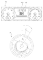
6 is a diagram referred to explain an exemplary operation for disabling the touch sensor 510 based on the rotation angle of the steering wheel 31, according to an embodiment of the present invention. For the sake of understanding, it is assumed that the touch sensor 510 disposed on the steering wheel 31 includes the four sensing areas 511, 512, 513, and 514 shown in FIG. 5A. It is also assumed that the image corresponding to the user input to the touch sensor 510 is displayed by the first display 141a included in the instrument panel 34. [
Referring to FIG. 6, the steering wheel 31 and the dashboard 34 may be functionally coupled by the controller 170.
For example, the driver can rotate the steering wheel 31 in various situations. For example, the driver can operate the steering wheel 31 clockwise or counterclockwise in order to drive the curve formed road, or turn left / right. For example, in order to avoid collision with nearby obstacles (e.g., pedestrians, other vehicles), the driver can rapidly rotate the steering wheel 31. [ In this case, a signal corresponding to the rotation angle of the steering wheel 31 detected by the rotation angle sensor disposed on the rotation axis of the steering wheel 31 is provided to the control unit 170, so that the control unit 170 controls the steering wheel 31 ) Is in a rotated state and the rotation angle can be sensed.
Specifically, the control unit 170 compares the rotation angle [theta] of the steering wheel 31 detected by the rotation angle sensor with the reference angle [theta] R previously stored in the memory 130 so that the rotation angle [ It is possible to judge whether or not it is larger than the reference angle? R. If the angle? Of the clockwise rotation of the steering wheel 31 exceeds the reference angle? R , the vehicle 1 does not correspond to the activation condition of the touch sensor 510 Can be output. For example, the controller 170 may control the first display 141a to display an indicator 610 that indicates that the function control using the steering wheel 31 is impossible. In this case, the vehicle 1 may deactivate the touch sensor 510, so that even if the user touches the touch sensor 510, the vehicle 1 may not respond thereto. In addition, the light output unit 144 may output light of a predetermined color and a blinking period corresponding to the deactivation state of the touch sensor 510. Accordingly, the driver can easily grasp that the current execution of the function using the touch sensor 510 is impossible. Further, when the steering wheel 31 is rotated for a curve, left / right turn, obstacle avoidance, etc., the execution of all the functions using the touch sensor 510 of the steering wheel 31 is fundamentally limited, . ≪ / RTI >
Figs. 7A to 7C show an exemplary operation in which the vehicle 1 controls a wiper based on user input, in accordance with an embodiment of the present invention. For the sake of understanding, it is assumed that the touch sensor 510 disposed on the steering wheel 31 includes the four sensing areas 511, 512, 513, and 514 shown in FIG. 5A. It is also assumed that the image corresponding to the user input to the touch sensor 510 is displayed by the first display 141a included in the instrument panel 34. [
First, referring to FIG. 7A, the driver may desire to drive the wiper 13. To this end, the driver may apply a user input 710 to the first sensing area 511. The controller 170 may sense the user input 710 for the first sensing area 511 based on the sensing signal provided from the touch sensor 510 in response to the user input 710. [ For example, the user input 710 may be a single tapping in which the first sensing area 511 is touched once within a time limit.
Vehicle 1 may select a function corresponding to user input 710, based on user input 710. [ Specifically, the control unit 170 can select a specific function corresponding to the user input 710 among a plurality of functions executable in the vehicle 1, and execute the selected function. For example, with the wiper turned off, the user input 710 for the first sensing area 511 may be mapped to the wiper turn-on function.
Accordingly, the control unit 170 can control the first display 141a to execute the wiper turn-on function and display an image indicating that the wiper turn-on function has been executed, as shown in the figure. In this case, the controller 170 may control the first display 141a to display an indicator 721 indicating that the wiper is operated at a predetermined minimum speed when the wiper turn-on function is executed. In addition, the controller 170 may control the light output unit 144 to output light of predetermined color and blink period corresponding to the turn-on function of the wiper.
Next, referring to FIG. 7B, the driver may desire to increase the operating speed of the wiper 13. FIG. To this end, the driver may apply a user input 720 to the first sensing area 511. The controller 170 may sense the user input 720 for the first sensing area 511 based on the sensing signal provided from the touch sensor 510 in response to the user input 720. [ For example, the user input 720 may be sweeping from the outside to the inside along the rim 31a in the first sensing area 511, as shown.
Vehicle 1 may select a function corresponding to user input 720, based on user input 720. [ Specifically, the control unit 170 can select a specific function corresponding to the user input 720 among a plurality of functions executable on the vehicle 1, and execute the selected function. For example, with the wiper turned on, the user input 720 for the first sensing area 511 may be mapped to the function of increasing the wiper operating speed.
Accordingly, the controller 170 can perform the function of increasing the wiper operating speed. The controller 170 may also control the first display 141a to display an indicator 722 that guides the increased wiper operating speed in accordance with the user input 720, as shown. In addition, the controller 170 may control the light output unit 144 to output light of predetermined color and blink period corresponding to the function of increasing the operating speed of the wiper.
On the other hand, although not shown, the driver may want to reduce the operating speed of the wiper. To this end, the driver may apply user input to the first sensing area 511 in a direction opposite to the sweeping direction of the user input 720. The controller 170 may perform a function of reducing the operating speed of the wiper in response to user input in a direction opposite to the sweeping direction of the user input 720 with respect to the first sensing area 511. [
Next, referring to FIG. 7C, the driver may desire to stop driving the wiper 13. To this end, the driver may apply a user input 730 to the first sensing area 511. The controller 170 may sense the user input 730 for the first sensing area 511 based on the sensing signal provided from the touch sensor 510 in response to the user input 730. [ For example, the user input 730 may be a double tapping in which the first sensing area 511 is touched twice within a time limit while the wiper is in operation.
Vehicle 1 may select a function corresponding to user input 730, based on user input 730. Specifically, the control unit 170 can select a specific function corresponding to the user input 730 among a plurality of functions executable on the vehicle 1, and execute the selected function. For example, with the wiper turned on, the user input 730 to the first sensing area 511 may be mapped to the wiper turn off function.
Accordingly, the control unit 170 may control the first display 141a to perform a wiper turn-off function and to display an indicator 723 indicating that the wiper has been turned off, as shown. In addition, the controller 170 may control the light output unit 144 to output light of predetermined color and blink period corresponding to the turn-off function of the wiper.
8A and 8B show an exemplary operation in which the vehicle 1 controls an air conditioning apparatus based on a user input according to an embodiment of the present invention. For the sake of understanding, it is assumed that the touch sensor 510 disposed on the steering wheel 31 includes the four sensing areas 511, 512, 513, and 514 shown in FIG. 5A. It is also assumed that the image corresponding to the user input to the touch sensor 510 is displayed by the first display 141a included in the instrument panel 34. [
First, referring to FIG. 8A, the driver may turn on the air conditioner. To this end, the driver may apply a user input 810 to the second sensing area 512. The controller 170 may sense the user input 810 for the second sensing area 512 based on the sensing signal provided from the touch sensor 510 in response to the user input 810. [ For example, the user input 810 may be a single tapping that touches the second sensing area 512 once within a time limit.
Vehicle 1 may select a function corresponding to user input 810, based on user input 810. [ Specifically, the control unit 170 can select a specific function corresponding to the user input 810 among a plurality of functions executable in the vehicle 1, and execute the selected function. For example, with the air conditioner turned off, the user input 810 to the second sensing area 512 may be mapped to the function of turning on the air conditioner.
Accordingly, the control unit 170 can control the first display 141a to execute the air conditioner turn-on function and display an image guiding that the air conditioner is turned on. For example, as shown in the figure, the control unit 170 controls the air conditioner so that, when executing the function of turning on the air conditioner, the control unit 170 controls the air conditioner to display an image including information about the temperature (for example, 25 degrees) The display 141a can be controlled. Also, the controller 170 may control the light output unit 144 to output light of a predetermined hue and blink period corresponding to the turn-on function of the air conditioner.
On the other hand, the control unit 170 may control the first display 141a to display information that guides a function that is already being executed when the user input 810 is received. For example, when the user input 810 is received while the wiper-related function is being executed as shown in FIGS. 7A and 7B, the controller 170 displays an indicator 801 that indicates that the wiper-related function is being executed The first display 141a can be controlled.
Next, referring to FIG. 8B, the driver may desire to reduce the temperature set in the air conditioner. To this end, the driver may apply a user input 820 to the second sensing area 512. The controller 170 may sense the user input 820 for the second sensing area 512 based on the sensing signal provided from the touch sensor 510 in response to the user input 820. [ For example, the user input 820 may be sweeping the second sensing area 512 from the inside to the outside along the rim 31a, as shown.
Vehicle 1 may select a function corresponding to user input 820, based on user input 820. [ Specifically, the control unit 170 can select a specific function corresponding to the user input 820 among a plurality of functions executable in the vehicle 1, and execute the selected function. For example, with the air conditioner turned on, the user input 820 for the second sensing area 512 may be mapped to a function of decreasing the set temperature of the air conditioner.
Accordingly, the control unit 170 can perform the function of reducing the set temperature of the air conditioner. The control unit 170 may also control the first display 141a to display an image guiding the set temperature of the reduced air conditioner (e.g., 20 degrees) according to the user input 820, as shown . In addition, the controller 170 may control the light output unit 144 to output light of predetermined color and blink period corresponding to the function of decreasing the set temperature of the air conditioner.
In one embodiment, the controller 170 may determine, based on the length of the user input 820, to what extent the set temperature of the air conditioner is to be reduced. For example, the longer the length of the user input 820, the lower the set temperature of the air conditioner.
In one embodiment, the controller 170 may determine, based on the number of user inputs 820, how much the set temperature of the air conditioner is to be reduced. For example, whenever the user input 820 is re-applied, the controller 170 may lower the set temperature of the air conditioner by 1 degree. For example, when the set temperature of the air conditioner is 25 degrees as shown in FIG. 8A, when the user input 820 is applied 5 times, the controller 170 can reduce the set temperature of the air conditioner to 20 degrees as shown in FIG. 8B.
On the other hand, although not shown, the driver can increase the set temperature of the air conditioner. To this end, the driver may apply user input to the second sensing area 512 in a direction opposite to the sweeping direction of the user input 820. The controller 170 may perform a function of increasing the set temperature of the air conditioner in response to a user input in a direction opposite to the sweeping direction of the user input 820 with respect to the second sensing area 512. [
9A and 9B show an exemplary operation in which the vehicle 1 controls a turn signal lamp based on a user input according to an embodiment of the present invention. For the sake of understanding, it is assumed that the touch sensor 510 disposed on the steering wheel 31 includes the four sensing areas 511, 512, 513, and 514 shown in FIG. 5A. It is also assumed that the image corresponding to the user input to the touch sensor 510 is displayed by the first display 141a included in the instrument panel 34. [
First, referring to FIG. 9A, the driver may turn on the left direction indicator. To this end, the driver may apply a user input 910 mapped to more than one of the plurality of sensing areas 511, 512, 513, and 514. For example, as shown, the user input 910 may be for a first sensing region 511 and a second sensing region 512. The controller 170 responds to the user input 910 to select a user input 910 for the first sensing area 511 and the second sensing area 512 based on the sensing signal provided from the touch sensor 510 Can be detected. For example, the user input 910 may be sweeping from one point of the second sensing area 512 to a point of the first sensing area 511.
Vehicle 1 may select a function corresponding to user input 910, based on user input 910. [ Specifically, the control unit 170 can select a specific function corresponding to the user input 910 among a plurality of functions executable in the vehicle 1, and execute the selected function. For example, the user input 910 may be mapped to the function of turning on the left turn indicator.
Thereby, the vehicle 1 can control the first display 141a to perform the left turn indicator turn on function and display the image indicating that the left turn indicator is turned on. For example, as shown, the control unit 170 can control the first display 141a to display an indicator 921 to indicate that the left turn indicator is lit when the function of turning on the left turn indicator is executed have. In addition, the controller 170 may control the light output unit 144 to output light having a predetermined hue and blink period corresponding to the turn-on function of the left turn indicator lamp.
Although not shown, the controller 170 can turn off the left direction indicator light in response to a user input in a direction opposite to the user input 910 in a state in which the left direction indicator is lit. For example, when sweeping is connected from one point of the first sensing area 511 to one point of the second sensing area 512 through the touch sensor 510, the controller 170 controls the left direction indicator Can be turned off. In this case, the indicator 921 may disappear from the first display 141a.
Next, referring to FIG. 9B, the driver may turn on the right direction indicator. To this end, the driver may apply a user input 920 mapped to more than one of the plurality of sensing areas 511, 512, 513, and 514. For example, as shown, the user input 920 may be for a third sensing area 513 and a fourth sensing area 514. The controller 170 responds to the user input 920 to select a user input 920 for the third sensing area 513 and the fourth sensing area 514 based on the sensing signal provided from the touch sensor 510 Can be detected. For example, the user input 920 may be sweeping from one point of the fourth sensing region 514 to a point of the third sensing region 513. [
Vehicle 1 may select a function corresponding to user input 920, based on user input 920. Specifically, the control unit 170 can select a specific function corresponding to the user input 920 among a plurality of functions executable in the vehicle 1, and execute the selected function. For example, the user input 920 may be mapped to the function of turning on the right turn indicator.
Thus, the vehicle 1 can control the first display 141a to perform the right turn indicator turn on function and display the image indicating that the right turn indicator is turned on. For example, as shown, the control unit 170 may control the first display 141a to display an indicator 922 to indicate that the right direction indicator is lit when the function of turning on the right direction indicator is turned on have. Also, the controller 170 may control the light output unit 144 to output light of a predetermined hue and blink period corresponding to the turn-on function of the right direction indicator.
On the other hand, although not shown, the controller 170 can perform the right turn indicator turn-off function in response to the user's input in the direction opposite to the user input 920, with the right turn indicator turned on. For example, when sweeping is connected from one point of the third sensing area 513 to one point of the fourth sensing area 514 through the touch sensor 510, the controller 170 controls the right direction indicator Can be turned off. In this case, the indicator 922 may disappear from the first display 141a.
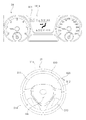
Figs. 10A to 10C show an exemplary operation in which the vehicle 1 according to an embodiment of the present invention sets a secret pattern required for switching between the non-travel mode and the travel mode, based on user input. For the sake of understanding, it is assumed that the touch sensor 510 disposed on the steering wheel 31 includes the four sensing areas 511, 512, 513, and 514 shown in FIG. 5A. It is also assumed that the image corresponding to the user input to the touch sensor 510 is displayed by the first display 141a included in the instrument panel 34. [
Referring first to Fig. 10a, the driver may wish to turn on the secret pattern. To do this, a driver may apply a user input 1010 that is mapped to at least one of a plurality of sensing areas 511, 512, 513, For example, as shown, the user input 1010 may be for a fourth sensing region 514. The controller 170 may sense the user input 1010 to the fourth sensing area 514 based on the sensing signal provided from the touch sensor 510 in response to the user input 1010. [ For example, the user input 1010 may be a gesture that repeats sweeping in one direction 1011 and sweeping in the opposite direction 1012 within a fourth sensing area 514 a predetermined number of times or more.
The vehicle 1 may select a function corresponding to the user input 1010 based on the user input 1010. [ Specifically, the control unit 170 can select a specific function corresponding to the user input 1010 among a plurality of functions executable on the vehicle 1, and execute the selected function. For example, the user input 1010 for the fourth sensing area 514 may be mapped to a secret pattern setting function.
Thus, as shown, the vehicle 1 can control the first display 141a to execute the secret pattern setting function and display the image requesting the setting of the secret pattern. Also, the controller 170 may control the light output unit 144 to output light having a predetermined hue and blink period corresponding to the secret pattern setting function.
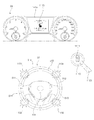
Next, referring to FIG. 10B, the driver may desire to set a secret pattern using the touch sensor 510 according to a request of the vehicle 1 as shown in FIG. 10A. To do this, a driver may apply user inputs 1021, 1022, 1023, 1024 to at least one of a plurality of sensing areas 511, 512, 513, For example, as shown, the user inputs 1021, 1022, 1023, and 1024 may be for all the sensing areas 511, 512, 513, and 514 included in the touch sensor 510.
The controller 170 controls the first to fourth sensing areas 511, 512, 513, and 514 based on the sensing signals provided from the touch sensor 510 in response to the user inputs 1021, 1022, 1023, The user input 1021, 1022, 1023, and 1024 can be detected. For example, the user inputs 1021, 1022, 1023, and 1024 may include a single tapping 1021 for the first sensing region 511, a double tapping 1022 for the third sensing region 513, And a single tapping 1024 for the second sensing area 512. The first sensing area 1024 may be input in the order of the double tapping 1023 for the first sensing area 512 and the single tapping 1024 for the second sensing area 512. [
The vehicle 1 may store in the memory 130 a secret pattern corresponding to the user inputs 1021, 1022, 1023, 1024. When the setting of the secret pattern is completed according to the user inputs 1021, 1022, 1023, and 1024, the control unit 170 displays the first display 141a Can be controlled.
Next, FIG. 10C illustrates a method of setting a secret pattern different from FIG. 10B. The driver may apply user inputs 1031, 1032, 1033, 1034 to at least one of the plurality of sensing areas 511, 512, 513, For example, as shown, the user inputs 1031, 1032, 1033, and 1034 may be for the first through third sensing areas 511, 512, and 513 included in the touch sensor 510.
The controller 170 controls the first to fourth sensing areas 511, 512, 513, and 514 based on the sensing signals provided from the touch sensor 510 in response to the user inputs 1031, 1032, 1033, The user inputs 1031, 1032, 1033, and 1034 can be detected. For example, the user inputs 1031, 1032, 1033, and 1034 may include a single tapping 1031 for the second sensing region 512, a reciprocating swipe 1032 for the first sensing region 511, Counterclockwise sweeping 1033 for the second sensing region 513 and single tapping 1034 for the second sensing region 512. [
Vehicle 1 may store in memory 130 a secret pattern corresponding to user inputs 1031, 1032, 1033, When the setting of the secret pattern is completed according to the user inputs 1031, 1032, 1033, and 1034, the control unit 170 displays the first display 141a Can be controlled.
After the setting of the secret pattern in the runnable mode is completed, when the vehicle 1 is turned off, the vehicle 1 can be automatically switched from the runnable mode to the runnable mode. Thereafter, the transition of the vehicle 1 from the non-travel mode to the travel mode can be executed only when a user input corresponding to the secret pattern is received. This will be described in more detail below with reference to Figs. 11A to 11C.
Figs. 11A to 11C show an exemplary operation of switching from the non-travel mode to the travel mode according to whether the vehicle 1 matches the user input and the secret pattern set in Fig. 10B according to an embodiment of the present invention.
First, referring to FIG. 11A, when the vehicle 1 is in the non-travelable mode, when the predetermined event occurs, the display unit 141 (not shown) displays an image guiding that the vehicle 1 is currently in the non- Can be controlled. The predetermined event may be, for example, an action in which the driver 1100 presses the start button 1110. [ In this case, the controller 170 may control the first display 141a to display the indicator 1112 corresponding to the disabled mode. When the start button 1110 is pressed by the driver 1100 in the non-travelable mode of the vehicle 1, the start indicator lamp 1111 disposed on the start button 1110 can be kept turned off .
11B, the driver can apply user inputs 1121, 1122, 1123, and 1124 to the touch sensor 510 to switch the vehicle 1 from the non-travel mode to the travel mode . For example, the user inputs 1121, 1122, 1123, and 1124 may include a single tapping 1121 for the fourth sensing region 514, a double tapping 1122 for the third sensing region 513, And a single tapping 1124 for the second sensing area 512. The first sensing area 1123 may be the same as the second sensing area 112,
The control unit 170 may compare the user inputs 1121, 1122, 1123 and 1124 with the user inputs 1021, 1022, 1023 and 1024 corresponding to the secret pattern shown in FIG. 10B. Specifically, the user inputs 1021, 1022, 1023, and 1024 may include single tapping for the first sensing region 511, double tapping for the third sensing region 513, double tapping for the fourth sensing region 514, And the single tapping for the second sensing area 512 while the user inputs 1121, 1122, 1123 and 1124 are in a different order than the user inputs 1021, 1022, 1023 and 1024 . Accordingly, the controller 170 determines that the user inputs 1121, 1122, 1123, and 1124 do not coincide with the predetermined secret pattern, and can maintain the non-travelable mode without switching to the travelable mode. In this case, the control unit 170 controls the display unit 110 to display an image including the indicator 1112 corresponding to the non-travelable mode and a message to guide that the user inputs 1121, 1122, 1123, The display 141a can be controlled.
11C, the driver may apply new user inputs 1131, 1132, 1133, and 1134 to the touch sensor 510 to switch the vehicle 1 from the non-travel mode to the travel mode . For example, the user inputs 1131, 1132, 1133, and 1134 may include a single tapping 1131 for the first sensing region 511, a double tapping 1132 for the third sensing region 513, a fourth sensing region 514 And a single tapping 1134 for the second sensing area 512. The first sensing area 1134 may be input in the order of the double tapping 1133 for the first sensing area 512 and the single tapping 1134 for the second sensing area 512. [
The control unit 170 may compare the user inputs 1131, 1132, 1133 and 1134 with the user inputs 1021, 1022, 1023 and 1024 corresponding to the secret pattern shown in FIG. 10B. Specifically, the user inputs 1021, 1022, 1023, and 1024 and the user inputs 1131, 1132, 1133, and 1134 match each other in order and order. Accordingly, the controller 170 determines that the user inputs 1131, 1132, 1133, and 1134 match the predetermined secret pattern, and can switch from the non-travelable mode to the travelable mode. In this case, the controller 170 displays a message to guide the user inputs 1131, 1132, 1133, and 1134 to coincide with the secret pattern, and to display an image including the indicator 1113 corresponding to the travelable mode, It is possible to control the light source 141a. 11A, when the start button 1110 is pressed by the driver 1100 in the travel possible mode, the vehicle 1 lights up the start indicator lamp 1111 disposed on the start button 1110 .
12 shows an exemplary operation in which the vehicle 1 stores state information of the vehicle 1 based on a user input according to an embodiment of the present invention. For the sake of understanding, it is assumed that the touch sensor 510 disposed on the steering wheel 31 includes the four sensing areas 511, 512, 513, and 514 shown in FIG. 5A. It is also assumed that the image corresponding to the user input to the touch sensor 510 is displayed by the first display 141a included in the instrument panel 34. [
Referring to FIG. 12, the driver may desire to receive the status of the vehicle 1 set at the present time as it is at the next boarding. To this end, the driver may apply user inputs 1211, 1212 to at least one of a plurality of sensing areas 511, 512, 513, 514. For example, as shown, the user inputs 1211 and 1212 may be for a first sensing region 511 and a second sensing region 512. The control unit 170 generates a user input 1211 for the first sensing area 511 and the second sensing area 512 based on the sensing signal provided from the touch sensor 510 in response to the user inputs 1211 and 1212. [ , 1212). For example, the user input 1210 may include a clockwise swipe 1211 in a first sensing region 511 and a counterclockwise swipe 1212 in a second sensing region 512.
The vehicle 1 can select a function corresponding to the user inputs 1211 and 1212 based on the user inputs 1211 and 1212. [ Specifically, the control unit 170 can select a specific function corresponding to the user inputs 1211 and 1212 among a plurality of functions executable in the vehicle 1, and execute the selected function. For example, the user inputs 1211 and 1212 may be mapped to the function of storing the current state information of the vehicle 1 in the memory 130. For example,
Thus, the vehicle 1 can execute the function of storing the state information of the vehicle 1. [ For example, as the function of storing the state information of the vehicle 1 is executed, at least one of the position of the driver's seat, the position of the mirror, the setting value of the air conditioner, May be stored in the memory 130.
In addition, the vehicle 1 may display an image for guiding that the function of storing the state information of the vehicle 1 has been executed. For example, as shown, the controller 170 may control the first display 141a to display an indicator 1213 that guides the current state of the vehicle 1 to be stored. The control unit 170 may control the light output unit 144 to output light of a predetermined color and blinking period corresponding to the function of storing the state information of the vehicle 1. [
13 shows an exemplary operation in which the vehicle 1 according to the embodiment of the present invention sets the state information stored in the vehicle 1 as shown in Fig. 12 on the basis of the user input.
Referring to FIG. 13, the driver may wish to apply the state information of the previously stored vehicle 1 to the current vehicle 1. To this end, the driver may apply user inputs 1311, 1312 to at least one of a plurality of sensing areas 511, 512, 513, 514. For example, as shown, the user inputs 1311 and 1312 may be for a first sensing region 511 and a second sensing region 512. The control unit 170 generates a user input 1311 for the first sensing area 511 and a second sensing area 512 for the second sensing area 512 based on the sensing signal provided from the touch sensor 510 in response to the user inputs 1311 and 1312. [ , 1312). For example, the user inputs 1311 and 1312 may include a counter-clockwise sweep 1311 in the first sensing area 511 and a clockwise sweep 1312 in the second sensing area 512. [
Vehicle 1 may select a function corresponding to user inputs 1311 and 1312 based on user inputs 1311 and 1312. [ Specifically, the control unit 170 can select a specific function corresponding to the user inputs 1311 and 1312 among a plurality of functions executable in the vehicle 1, and execute the selected function. For example, the user inputs 1311 and 1312 may be mapped to the function of setting the state information that has been stored at a specific point in time in the current vehicle 1.
Thus, the vehicle 1 can execute the function of acquiring the previously stored state information from the memory 130 and setting the acquired state information in the vehicle 1. [ For example, when the driver's seat back angle included in the stored state information is 90 degrees, the controller 170 can adjust the driver's seat back angle to 90 degrees according to the user inputs 1311 and 1312. [ For example, when the set temperature of the air conditioner included in the stored status information is 25 degrees, the controller 170 may turn on the air conditioner and change the set temperature to 25 degrees according to the user inputs 1311 and 1312 .
Further, the vehicle 1 may display an image for guiding that the function of setting the previously stored state information in the vehicle 1 has been executed. For example, as shown in the figure, the controller 170 controls the indicators 1321 and 1322 to guide each of the driver's seat, the side mirrors, and the set temperature to be adjusted according to the execution of the function of setting the stored state information to the vehicle 1. [ , 1323 of the first display 141a. In addition, the controller 170 may control the light output unit 144 to output light of predetermined color and blink period corresponding to the function of setting the stored state information to the vehicle 1. [
The embodiments of the present invention described above are not only implemented by the apparatus and method but may be implemented through a program for realizing the function corresponding to the configuration of the embodiment of the present invention or a recording medium on which the program is recorded, The embodiments can be easily implemented by those skilled in the art from the description of the embodiments described above.
The present invention may be embodied in other specific forms without departing from the spirit or essential characteristics thereof. Therefore, it is to be understood that the present invention may be embodied in many other specific forms without departing from the spirit or essential characteristics thereof. It is to be understood that the invention is not limited to the accompanying drawings, and all or some of the embodiments may be selectively combined so that various modifications may be made.