KR20170027219A - A safety swing stick tension device of a shade drive apparatus, and the shade drive apparatus and hoist apparatus using the same - Google Patents
A safety swing stick tension device of a shade drive apparatus, and the shade drive apparatus and hoist apparatus using the same Download PDFInfo
- Publication number
- KR20170027219A KR20170027219A KR1020150123867A KR20150123867A KR20170027219A KR 20170027219 A KR20170027219 A KR 20170027219A KR 1020150123867 A KR1020150123867 A KR 1020150123867A KR 20150123867 A KR20150123867 A KR 20150123867A KR 20170027219 A KR20170027219 A KR 20170027219A
- Authority
- KR
- South Korea
- Prior art keywords
- rotary
- swing
- string
- module
- stick
- Prior art date
- Legal status (The legal status is an assumption and is not a legal conclusion. Google has not performed a legal analysis and makes no representation as to the accuracy of the status listed.)
- Withdrawn
Links
- 238000000034 method Methods 0.000 claims abstract description 11
- 238000004519 manufacturing process Methods 0.000 abstract description 8
- 238000004804 winding Methods 0.000 description 22
- 208000027418 Wounds and injury Diseases 0.000 description 4
- 238000005065 mining Methods 0.000 description 4
- 230000002441 reversible effect Effects 0.000 description 4
- 238000000926 separation method Methods 0.000 description 4
- 206010003497 Asphyxia Diseases 0.000 description 3
- 238000001035 drying Methods 0.000 description 3
- 230000000452 restraining effect Effects 0.000 description 3
- 239000000243 solution Substances 0.000 description 3
- 230000008094 contradictory effect Effects 0.000 description 2
- 239000000463 material Substances 0.000 description 2
- 235000012431 wafers Nutrition 0.000 description 2
- 206010047700 Vomiting Diseases 0.000 description 1
- 229910052782 aluminium Inorganic materials 0.000 description 1
- XAGFODPZIPBFFR-UHFFFAOYSA-N aluminium Chemical compound [Al] XAGFODPZIPBFFR-UHFFFAOYSA-N 0.000 description 1
- 230000000712 assembly Effects 0.000 description 1
- 238000000429 assembly Methods 0.000 description 1
- 230000005540 biological transmission Effects 0.000 description 1
- 239000003638 chemical reducing agent Substances 0.000 description 1
- 239000000470 constituent Substances 0.000 description 1
- 238000010276 construction Methods 0.000 description 1
- 230000008878 coupling Effects 0.000 description 1
- 238000010168 coupling process Methods 0.000 description 1
- 238000005859 coupling reaction Methods 0.000 description 1
- 230000001419 dependent effect Effects 0.000 description 1
- 238000005516 engineering process Methods 0.000 description 1
- 239000004744 fabric Substances 0.000 description 1
- 230000005484 gravity Effects 0.000 description 1
- 238000001746 injection moulding Methods 0.000 description 1
- 230000000670 limiting effect Effects 0.000 description 1
- 239000007769 metal material Substances 0.000 description 1
- 239000000203 mixture Substances 0.000 description 1
- 230000004048 modification Effects 0.000 description 1
- 238000012986 modification Methods 0.000 description 1
- 230000002829 reductive effect Effects 0.000 description 1
- 230000003014 reinforcing effect Effects 0.000 description 1
- 238000005096 rolling process Methods 0.000 description 1
- 239000007787 solid Substances 0.000 description 1
- 230000007480 spreading Effects 0.000 description 1
- 238000003892 spreading Methods 0.000 description 1
- 230000035900 sweating Effects 0.000 description 1
- 230000008673 vomiting Effects 0.000 description 1
Images


Classifications
-
- E—FIXED CONSTRUCTIONS
- E06—DOORS, WINDOWS, SHUTTERS, OR ROLLER BLINDS IN GENERAL; LADDERS
- E06B—FIXED OR MOVABLE CLOSURES FOR OPENINGS IN BUILDINGS, VEHICLES, FENCES OR LIKE ENCLOSURES IN GENERAL, e.g. DOORS, WINDOWS, BLINDS, GATES
- E06B9/00—Screening or protective devices for wall or similar openings, with or without operating or securing mechanisms; Closures of similar construction
- E06B9/24—Screens or other constructions affording protection against light, especially against sunshine; Similar screens for privacy or appearance; Slat blinds
-
- B—PERFORMING OPERATIONS; TRANSPORTING
- B66—HOISTING; LIFTING; HAULING
- B66D—CAPSTANS; WINCHES; TACKLES, e.g. PULLEY BLOCKS; HOISTS
- B66D1/00—Rope, cable, or chain winding mechanisms; Capstans
- B66D1/02—Driving gear
- B66D1/04—Driving gear manually operated
-
- E—FIXED CONSTRUCTIONS
- E06—DOORS, WINDOWS, SHUTTERS, OR ROLLER BLINDS IN GENERAL; LADDERS
- E06B—FIXED OR MOVABLE CLOSURES FOR OPENINGS IN BUILDINGS, VEHICLES, FENCES OR LIKE ENCLOSURES IN GENERAL, e.g. DOORS, WINDOWS, BLINDS, GATES
- E06B9/00—Screening or protective devices for wall or similar openings, with or without operating or securing mechanisms; Closures of similar construction
- E06B9/24—Screens or other constructions affording protection against light, especially against sunshine; Similar screens for privacy or appearance; Slat blinds
- E06B9/26—Lamellar or like blinds, e.g. venetian blinds
- E06B9/38—Other details
-
- E—FIXED CONSTRUCTIONS
- E06—DOORS, WINDOWS, SHUTTERS, OR ROLLER BLINDS IN GENERAL; LADDERS
- E06B—FIXED OR MOVABLE CLOSURES FOR OPENINGS IN BUILDINGS, VEHICLES, FENCES OR LIKE ENCLOSURES IN GENERAL, e.g. DOORS, WINDOWS, BLINDS, GATES
- E06B9/00—Screening or protective devices for wall or similar openings, with or without operating or securing mechanisms; Closures of similar construction
- E06B9/24—Screens or other constructions affording protection against light, especially against sunshine; Similar screens for privacy or appearance; Slat blinds
- E06B9/40—Roller blinds
- E06B9/42—Parts or details of roller blinds, e.g. suspension devices, blind boxes
-
- E—FIXED CONSTRUCTIONS
- E06—DOORS, WINDOWS, SHUTTERS, OR ROLLER BLINDS IN GENERAL; LADDERS
- E06B—FIXED OR MOVABLE CLOSURES FOR OPENINGS IN BUILDINGS, VEHICLES, FENCES OR LIKE ENCLOSURES IN GENERAL, e.g. DOORS, WINDOWS, BLINDS, GATES
- E06B9/00—Screening or protective devices for wall or similar openings, with or without operating or securing mechanisms; Closures of similar construction
- E06B9/56—Operating, guiding or securing devices or arrangements for roll-type closures; Spring drums; Tape drums; Counterweighting arrangements therefor
- E06B9/68—Operating devices or mechanisms, e.g. with electric drive
- E06B9/76—Operating devices or mechanisms, e.g. with electric drive using crank handles
Landscapes
- Engineering & Computer Science (AREA)
- Structural Engineering (AREA)
- Architecture (AREA)
- Civil Engineering (AREA)
- Mechanical Engineering (AREA)
- Building Awnings And Sunshades (AREA)
Abstract
본 발명은 제조비용이 저렴하며 구성이 간단하며 안전하게 회전줄과의 작동을 통해 회전줄풀리를 구동시킴과 동시에 위험한 회전줄을 외부에서 잡아당길 때 늘어지거나 벌어지지 않도록 제한하여 회전줄에 의한 어린이 질식 사고를 원천적으로 방지 가능한 차양구동장치의 안전 스윙 스틱 텐션장치를 제공하기 위한 것으로, 회전줄(3)을 가지는 구동휠 부재의 복귀 기능을 갖는 차양구동장치(4b)에 결합되고, 소정각도 회전하며, 상기 차양구동장치(4b)로 인입 및 상기 차양구동장치(4b)로부터 인출되는 회전줄(3) 부위가 소정 각도로 외부에 위치시키도록 안내하는 스윙모듈(71); 및 결합부재(72d)에 의해 상기 스윙모듈(71)에 기다란 막대 모양의 몸체(72a)가 결합되어지고, 상기 회전줄(3a)이 상기 스윙모듈(71)에 결합되어지는 일 측면의 반대편 타단에 구비되는 회전수단(72b)에 의해 회동 가능하도록 팽팽하게 걸쳐져 지지되어지는 텐션스틱모듈(72); 을 포함하여, 상기 차양구동장치(4b) 하방으로 늘어진 회전줄(3)과 회전줄(3) 사이 혹은 회전줄(3)과 몸체(72a) 사이에서 어린아이의 머리가 끼어져 들어가지 않도록 회전줄(3)을 구속함과 동시에, 상기 스윙모듈(71)에 의해 상기 차양구동장치(4b)로부터 소정각도 이격된 하방 위치에서도 상기 회전줄(3)을 잡아당겨 차양구동장치(4b)를 구동하는 것이 가능한 것을 특징으로 한다.The present invention relates to an apparatus and a method for driving a rotary rope pulley with low manufacturing cost and a simple configuration and safely operating a rotary rope, and also to prevent a dangerous rotary rope from being stretched or flared when pulled from the outside, The present invention provides a safety swing stick tensioning device for a sunshade driving device capable of preventing an accident from occurring. The safety swing stick tensioning device is coupled to a sunshade driving device (4b) having a function of returning a driving wheel member having a rotating shaft (3) A swing module 71 for guiding the portion of the rotary string 3 that is pulled into the awning driving device 4b and pulled out from the awning driving device 4b to be positioned outside at a predetermined angle; Shaped body 72a is coupled to the swing module 71 by the engaging member 72d and the swing module 71 is coupled to the swing module 71, A tension stick module 72 which is stretched and supported so as to be rotatable by means of a rotating means 72b provided on the tension stick module 72; (3) between the rotary string (3) and the rotary string (3) and the body (72a) which are laid down below the sun shade driving device (4b) The swinging rod 3 is constrained and the swinging rod 3 is pulled by the swing module 71 at a lower position spaced by a predetermined angle from the swinging drive device 4b to drive the swinging drive device 4b And the like.
Description
본 발명은 블라인드나 루버 등의 차양구동장치에 관한 것으로, 특히 롤/콤비/트리플 블라인드의 스크린 회전봉, 베네치안/ 로만쉐이드/ 허니콤 블라인드의 슬랫의 각도조절이나 권취용 회전봉 및 버티칼 블라인드의 회전봉 (이하 상기 회전봉들을 “회전축"이라 칭함) 또는 세탁물 건조대의 회전체 등을 손으로 잡아당겨 구동시켜주는 수동구동용 볼 체인과 회전줄 (이하 두 가지를 "수동줄" 하나로 통칭함) 을 안전하게 수납하는 어린이 안전보호를 위한 차양구동장치의 안전 스윙 스틱 텐션장치, 그리고 이를 채용하는 차양구동장치 및 호이스트 장치에 관한 것이다.
BACKGROUND OF THE INVENTION 1. Field of the Invention The present invention relates to a sun-blind driving apparatus such as a blind, a louver, and the like, and more particularly to a screen rotating bar of a roll / combination / triple blind, a rotating bar of a Venetian / roman shade / honeycomb blind, (Hereinafter, referred to as " rotating shaft ") or a ball chain for manual driving that pulls the rotating body of the laundry drying table by hand and drives the rotating chain A safety swing stick tensioning device for a sunshade driving device for protecting children's safety, a shovel driving device and a hoist device employing the same.
일반적으로 실내 혹은 실외에 설치되는 소형 호이스트 기기의 일 종류인 차양은 창문틀에 설치되어 창문을 통한 채광 및 채광을 선택적으로 행할 수 있도록 하는 것으로, 그 구조적인 특징에 따라 긴 슬랫이 수평 방향으로 배치되고 상하 방향으로 유동되면서 선택적 채광을 행하는 베니션 블라인드와 슬랫이 수직 방향으로 배치되고 좌우로 유동되면서 선택적 채광을 행하는 버티컬 블라인드, 그리고 고정된 위치에서 회동되도록 마련되고 각도를 조절하는 방식의 루버가 다수 구비되는 루버타입 등의 슬랫 타입과 수평 방향으로 배치되는 롤에 스크린이 감겨져 상하 방향으로 유동되어 선택적 채광을 이루는 롤 블라인드와 주름진 원단을 접거나 펼치는 방식으로 채광 혹은 차광하는 허니콤 및 플리티드 블라인드 등과 같은 스크린 타입 등이 있다.
Generally, a kind of small hoist device installed in a room or outdoor is installed in a window frame so that a mining and mining through a window can be selectively performed, and a long slat is arranged horizontally A venetian blind which vertically moves and vertically moves, a vertical blind which vertically arranges the slats, a vertical blind which selectively moves to the left and right, and a plurality of louvers arranged to rotate at a fixed position Such as a louver type and a horizontally arranged roll, a rolled blind that is rolled up and down to form selective light, and honeycomb and pleated blinds that light or shade by folding or spreading corrugated fabric Screen type.
이러한 차양은 통상적으로 견인줄이나 스크린 자체가 감겨지거나 풀어지도록 임의의 고정부재에 회동 가능하도록 단단히 고정되는 권취부재가 구비되고 지지부재 또는 다수 슬랫 내지 스크린 중 어느 하나 혹은 그 복합으로 중량체를 형성하거나 구비되며 그에 결합된 견인줄 혹은 스크린이 중력에 의해 권취부재로부터 풀어지도록(권해) 구비되며, 모터 등 전기 동력이나 수동동력으로 견인줄 혹은 스크린을 권취부재에 감아(권취) 슬랫 혹은 스크린을 특정 의도한 높이에 위치시키거나 소정각도를 회전시키는 방식으로 작동되는데, 전기 동력이나 수동동력이 권취부재에 가해지지 않을 때는 중량체의 자중에 의해 권취부재가 하강 회동되는 것을 제동함과 동시에 동력이 가해질 때는 권취부재의 회동구동을 가능하게 하는 호이스트구동장치(통상적으로 “클러치”라 호칭함)가 필수적이다.
Such an awl is usually provided with a winding member that is firmly fixed to an arbitrary fixing member such that the towing line or the screen itself can be wound or unwound so as to be rotatable on an arbitrary fixing member, and a weight member is formed or formed by any one of a supporting member, (Pulled) from the winding member by means of gravity, and the pulling line or screen is wound (wound) on the winding member by an electric or manual power such as a motor, and the slat or screen is moved to a specific intended height When the electric power or the manual power is not applied to the winding member, it is braked that the winding member is downwardly rotated by the weight of the weight, and at the same time, when the power is applied, A hoist drive device capable of turning driving Hereinafter referred to as "clutch") is essential.
또, 실내 혹은 실외에 설치되는 호이스트 기기의 일 종류로서 빨래건조대를 들 수 있는데 역시 상술한 차양과 마찬가지이며 전기 동력이나 수동동력이 권취부재에 가해지지 않을 때는 중량체의 자중에 의해 권취부재가 하강 회동되는 것을 제동함과 동시에 동력이 가해질 때는 권취부재의 회동구동을 가능하게 하는 호이스트구동장치가 필수적이다.
As a kind of hoist machine installed in a room or outdoors, a laundry drying machine can also be used, which is similar to the above-described awnings. When the electric power or the manual power is not applied to the winding member, It is necessary to provide a hoist driving device which can brak down the rotation and enable the rotation of the winding member when the power is applied.
이외에도 다양한 호이스트 기기가 있지만 그 구성과 작동관계는 대동소이하고 이와 같은 사실은 당업자들에게 자명하므로 더 이상의 다른 호이스트 기기에 대한 설명은 이하 생략하기로 한다.
In addition, there are various hoist devices, but their configuration and operation relationship are quite different and the facts will be obvious to those skilled in the art, so further descriptions of other hoist devices will be omitted below.
한편, 도 1은 이러한 호이스트 기기의 일종인 통상의 롤 블라인드 분해사시도와 롤 단면도이며, 도 2는 롤 블라인드 클러치를 나타낸 분해사시도이며, 도 3은 롤 블라인드 클러치 결합상태 단면도인데, 이는 이러한 클러치가 필요한 대표적인 예로써 선정하여 상세하게 그 구성과 작동관계를 설명하기 위함으로. 이를 통하여 본 발명과 관련된 배경기술을 설명하기로 한다.
Fig. 1 is an exploded perspective view showing a roll blind clutch, and Fig. 3 is a cross-sectional view showing a roll blind clutch. This is a state in which such a clutch is necessary As a representative example, it is selected in detail to explain its composition and operation relationship. The background art relating to the present invention will now be described.
먼저, 도 1의 (a)에 도시된 바와 같이, 종래 차양의 하나인 롤 블라인드는 창문틀 상측에 고정 설치되는 헤드레일(1a); 상기 헤드레일(1a)의 하측에 배치되는 롤 스크린(2) 및 상기 헤드레일(1a)의 일 측단에 삽입 설치되어 상기 롤 스크린(2)을 회전구동과 제동을 가능하게 하는 Wrap-Spring을 사용하는 스프링클러치(spring clutch, 4a); 타단을 마감하는 마개(5a); 를 포함하여 이루어지고, 도 1의 (b)에 도시된 바와 같이, 상기 롤 스크린(2)은 체결부재(2b2)와 스크린시트(2b1)로 구비되는 스크린(2b); 길이방향 내주면에 돌출턱이 형성되고, 외주면에는 스크린시트 체결구(2a3)가 일체 형성된 내부가 중공이며 회전 동력축을 겸하며 스크린시트(2b1)를 권취하고 권해하는 환봉(2a1)으로 마련되는 권취부재(2a); 로 이루어지며, 상기 권취부재(2a)의 일 측단부에는 스프링클러치(4a)가 삽입되고, 타단은 마개(5a)가 끼워지며, 폭이 기다란 스크린시트(2b1)의 중량을 고려하여 도 1의 (c)에 도시한 바와 같이, 환봉(2a1) 내부에 처짐보강부재(2a2)를 더 포함하여 구성하거나 일체로 형성하기도 하는데, 통상적으로는, 상기 환봉(2a1)은 회전축과 권취 또는 권해(捲解)를 겸하게 하여 매우 경제적인 구조를 가지고 있다고 할 수 있으며, 환봉 제조방식은 알루미늄이나 플라스틱 소재로 사출 성형되지만, 내부는 제조비용 문제로 인하여 비어 있다.
First, as shown in FIG. 1 (a), a roll blind, which is one of conventional shovels, includes a
이와 같은 롤 블라인드는, 상기 스프링클러치(4a)의 일 측에 구비되어 권취부재(2a)인 환봉(2a1)을 회전시키도록 사용자에 의해 수동으로 회전줄(3)을 조작하게 하거나, 전동 모터(미도시)를 장착하여 권취부재(2a)인 환봉(2a1)을 전기 동력으로 회전시키는 방식으로 상기 롤 스크린(2)의 스크린(2b)이 권취부재(2a)에 권취되거나 권취부재(2a)로부터 권해되어 선택적으로 차광과 채광을 가능하게 한다.
Such a roll blind is provided on one side of the
또한, 상기 스프링클러치(4a)는 도 2에 도시한 바와 같이, 걸림부(4a2‘)가 일체로 형성된 랩 스프링(Wrap Spring)으로 구비되는 클러치부재(4a2); 클러치부재(4a2)가 삽입되어 마련되는 고정자(stator, 4a1); 회전줄(3)이 걸려 회전하는 회전줄풀리(4a3a)가 일 측단에 일체로 형성되어 있고 클러치부재(4a2)인 랩 스프링 끝단에 일체로 형성된 걸림부(4a2‘)를 랩 스프링 몸체가 벌어지는 방향으로 밀어 고정자(4a1)와 클러치부재(4a2) 사이의 마찰 제동력을 해제시키고 회전시키는 구동회전자(Sleeve, 4a3b)가 타측에 일체로 형성되고 고정자(4a1)의 외주면에 끼워지는 구동휠 부재(4a3); 외주면이 환봉(2a1)의 스크린시트 체결구(2a3)에 끼워지도록 돌출턱(4a41)이 형성되고 내주면은 구동부재(4a3)와 고정자(4a1)에 끼워져 결합되며 클러치부재(4a2)의 랩 스프링 몸체가 좁혀지는 방향으로 밀어, 고정자(4a1)와 클러치부재(4a2) 사이의 마찰제동력을 증대시키는 제동 걸림턱(미도시)이 형성된 픽업부재(4a4); 를 포함하여 이루어지며, 사용자가 회전줄(3)을 잡아당긴 힘으로 구동부재(4a3)의 일 구성인 회전줄풀리(4a3a)를 회전시키면 (도 3의 실선 화살표 방향), 구동회전자(4a3b)가 클러치부재(4a2)의 걸림부(4a2‘)를 랩 스프링 몸체가 벌어지는 방향으로 밀어 고정자(4a1)와 클러치부재(4a2) 사이의 마찰 제동력을 해제함과 동시에 픽업부재(4a4)의 제동 걸림턱(미도시)을 밀어 회전시킴으로서 외주면에 형성된 돌출턱(4a41)이 환봉(2a1)의 스크린시트 체결구(2a3)를 회전방향으로 밀어 권취부재(2a)인 환봉(2a1)을 회전시키게 되는 것이고, 사용자가 회전줄(3)의 잡아당김을 멈추면 스크린시트(2b1)의 하중에 따라 권취부재(2a)인 환봉(2a1)에 회전력이 작용하게 되고, 이 회전력은 종국에는 픽업부재(4a4)를 회전시키게 되지만, 픽업부재(4a4)의 제동 걸림턱(미도시)을 클러치부재(4a2)의 랩 스프링 몸체가 좁혀지는 방향으로 밀어 (도 3의 점선 화살표 방향), 고정자(4a1)와 클러치부재(4a2) 사이의 마찰 제동력을 증대시킴으로서 환봉(2a1)을 회전 정지시킨다.
2, the
이와 같은 스프링클러치(4a)는 랩 스프링이라는 일체로 형성된 하나의 기계요소가 제동 및 구동을 동시에 담당하게 하고, 그 제작이 매우 용이하며 무엇보다도 값이 매우 저렴하여 차양의 종류나 빨래기기 등 호이스트 기기에서 대부분 사용되고 있으며, 호이스트 기기의 종류에 따라 이를 적용하기 위해 다양한 권취부재를 달리 갖고 있을 뿐이어서 그에 맞게 연결되도록 구비되는 픽업부재(4a4)가 다를 뿐 그 원리는 동일하다 할 수 있고, 구동부재(4a3) 역시, 수동동력 혹은 전기 동력을 사용하느냐에 따라, 혹은 구동 특징에 맞게 또 다른 클러치 형태를 추가 적용하는 등 그 세부구성이나 형태가 다양할 뿐이다.
Such a
한편, 다양한 호이스트 기기에 적용되는 또 다른 클러치로서 제동과 구동을 동시에 겸할 수 있는 웜 및 웜휠이 적용하기도 하지만 플라스틱 소재를 사용할 경우 그 힘을 버티지 못하며, 금속재질의 경우에는 사출과 같은 성형공법을 사용하기가 곤란하여 일일이 깍거나 전조하는 방식으로 제조함으로써 (특히 빨래건조대 및 어닝) 웜의 제작이 쉽지 않고 제조비용이 높아 하중이 작고 상대적으로 저렴한 롤 블라인드 , 베니션 블라인드 등 대부분의 차양 등의 적용에 한계를 보여 고하중 중량체의 제동 및 승강, 하강 구동이 필수적이면서 상대적으로 고가인 빨래건조대나 어닝 등에만 제한적으로 적용되고 있는 실정이며, 이외에도 다양한 또 다른 클러치가 공지되어 있지만 그 구성과 작동관계는 당업자들이 쉽게 이해할 수 있으므로 더 이상의 다른 호이스트 기기에 적용되는 제동 및 구동장치에 대하여는 자세한 설명은 생략하기로 한다.
On the other hand, another clutch applied to various hoist devices is a worm and a worm wheel that can be combined with both braking and driving. However, when the plastic material is used, the force can not be maintained. In the case of a metal material, It is difficult to manufacture worms (especially in laundry drying hobs and awnings) due to difficulty in making the worms, and the manufacturing cost is high, so that the application of most of the shovels such as roll blinds and venetian blinds having relatively small loads and relatively low loads The present invention has been applied to a limited range of laundry hats and awnings which are relatively expensive and which require braking, lifting and lowering of a heavy load weight, and various other clutches are known. However, So that they can be easily understood. Detailed description with respect to the braking and driving devices in the host device will be omitted.
그러나 수동 작동 호이스트 기기에 적용되는 클러치에 사람의 힘을 전달하기 위해서는 구동부재에 일체로 형성되거나 결합된 회전줄풀리와 그에 끼워지는 소정길이의 루프형 회전줄을 사용할 수밖에 없는데, 그 이유로는 호이스트 기기의 승강거리나 사람이 느끼는 힘을 줄이기 위한 감속기의 채택 등으로 인하여 잡아당겨야 하는 회전줄의 길이가 승강거리보다 크고 다양하기 때문으로, 이러한 루프형 회전줄은 매우 값싸고 합리적인 동력전달수단이어서 거의 모든 호이스트기기에 장착되어 사용되고 있다.
However, in order to transmit a human force to a clutch applied to a manually operated hoist apparatus, it is inevitable to use a loop-shaped pulley integrally formed or coupled to the driving member and a loop-shaped rotating barrel of a predetermined length to be fitted thereto, Because the length of the rotary string to be pulled out due to the adoption of the speed reducer to reduce the lift distance or the power felt by the person is larger and diverse than the vertical distance of the lifting distance, the loop rotary string is a very cheap and rational power transmission means, It is used in hoist equipment.
이러한 루프형 회전줄은 통상적으로 일자형 볼 체인과 코드 줄의 끝단을 이어 붙여 제작되며 기어특성을 갖는 볼 체인용 회전줄풀리나 또는 단지 마찰력으로만 구동하는 코드줄에 맞도록 적절한 회전줄풀리가 제작되어 보급되어 왔다.
Such a loop type rotating string is usually formed by connecting a straight type ball chain and the end of a cord string to a rotary string pulley for a ball chain having a gear characteristic or a suitable rotary string pulley for a cord string driven only by frictional force .
그러나 루프형 회전줄은 최근 큰 사회문제를 일으키는 주범으로 대두 되고 있는데 그 이유는 이러한 루프형 회전줄이 영유아 및 어린아이의 목걸림 질식 안전사고의 주범이기 때문으로 이를 해결하기 위해, 특히 블라인드 업계는 다양한 노력을 지속적으로 기울이고 있는 실정이나 마땅한 대안이 아직 제시되지 않는 실정이었다.
However, the loop loop has recently become a major cause of social problems because the loop loop is the main cause of accidents in the neck and throat of infants and young children. In order to solve this problem, It has been a fact that many efforts are continuously being made and the alternative which is not worthy to be presented yet.
이에 본 출원인은 이러한 루프형 회전줄이 가지는 어린이 질식사고의 문제를 해결하기 위해 선출원(등록특허 10-1295684, 등록특허 10-1469910)으로 상술한 구동휠 부재의 구동회전자(Sleeve, 도 2 참조, 4a3b)를 구동휠 부재와 분리시키고, 회전줄풀리를 어느 일 방향으로 회전시키는 경우에는 같이 회전하나, 일 방향으로 회전줄풀리에 의해 함께 회전한 직후에 반대방향으로 자체적으로 회전할 경우에는 회전줄풀리를 차양 회전축과 독립적으로 회전하게 하는 양방향구동 클러치와 사용자가 회전줄을 놓아 수동 작동을 정지시키면, 양방향구동 클러치를 구성하는 리테이너를 역회전시키는 역회전수단을 더 포함시켜 구성한 구동휠 부재의 복귀 기능을 갖는 차양구동장치(도 4의 4b 참조)를 해법으로 제시한 바 있으며, 이의 자세한 구성과 작동원리는 선출원을 참조하면 되므로 이하에서는 더 이상의 설명은 생략한다.
In order to solve the problem of child suffocation caused by the loop-shaped rotary string, the applicant of the present invention has proposed a driving circuit of a driving wheel member (Sleeve, see Fig. 2, refer to Patent Document 10-1295684, 4a3b are separated from the drive wheel member and rotate together when the rotary pulley is rotated in one direction, but when it rotates itself in the opposite direction immediately after it is rotated together by the rotary pulley in one direction, A bi-directional drive clutch for causing the pulley to rotate independently of the sun shade rotation axis, and a reverse rotation means for reversing the retainer constituting the bi-directional drive clutch when the user releases the rotation line to stop the manual operation, (See 4b in Fig. 4) as a solution, and the detailed construction and operation principle of the shovel driving device Since when the bath below further description will be omitted.
한편, 이러한 구동휠 부재의 복귀 기능을 갖는 차양구동장치(도 4의 4b 참조)에 루프 회전줄(도 1의 3참조)을 안전하게 사용하는 방법을 도 4를 통하여 당업자에게 설명하고자 하며 그 이유로는 본 발명과 밀접한 배경기술이기 때문이다 (단, 도 4의 기술은 본 출원 시점에 있어서 공지기술은 아니다).
On the other hand, a method for safely using the loop rotation string (see 3 in Fig. 1) on the awning drive device having the function of returning the drive wheel member (see 4b in Fig. 4) will be explained to a person skilled in the art through Fig. (Although the technique of FIG. 4 is not a known technology at the time of the present application).
우선 도 4에 도시한 바와 같이, 어린이 질식사를 방지하도록 종래의 루프 회전줄(3, 도 1참조)을 안전하게 만들기 위해 통상적인 길이가 약 1.5미터인 루프 회전줄(3)을 상중하로 3등분하는데 상단회전줄(3a)은 사용자(어른)가 한번 잡아당길 수 있는 길이(One pulling stroke length)로 약 50cm ~ 70cm, 중간회전줄(3b)은 약 10cm ~ 30cm, 하단회전줄(3c)은 약 70cm로 자른 후에 상단회전줄(3a)과 중간회전줄(3b)은 각각 2개의 스트퍼겸용연장부재(3d)를 이용하여 분리되지 않도록 연장하고, 중간회전줄(3b)과 하단회전줄(3c) 사이에는 어린이가 잡으면 즉각 분리되는 분리수단(3e, Breaking Away device)을 양측에 각각 1개씩 2개를 쌍으로 조립하여 다시 전체적인 루프를 구성하고 이렇게 구성된 안전한 루프회전줄(3‘,이하 “안전 루프회전줄”이라 칭함)을 회전줄풀리(미도시)에 끼워 조립하되, 사용자(어른)가 양측 분리수단(3e) 위쪽의 안전 루프회전줄(3’)의 상단 및 중간회전줄(3a)(3b)을 잡는 부위의 높이를 바닥으로부터 약 170cm 이상 이격된 위치에 오도록 하는 방식으로 조립하면, 어린이가 잡는 부위(3c)와 어른이 잡는 부위(3a)(3b)를 분리수단(3e)을 통하여 의도적으로 뚜렷하게 분할 해 놓을 수 있으므로 어린이가 잡을 수 있는 170cm 이하에서 만일 어린이가 하단회전줄(3c)을 잡을 때는 즉각 분리되고 어른만 분리수단(3e) 위쪽의 상단 및 중간회전줄(3a)(3b)을 잡고 잡아당겨서 차양을 구동하도록 구성한다.
First of all, as shown in Fig. 4, to make safe the conventional loop rotary string 3 (see Fig. 1) to prevent child suffocation, the loop
이와 같이 안전 루프회전줄(3’)을 구성하는 이유는 우선 상단회전줄(3a)의 경우 어른이 잡아당기는 한 스트로크의 길이가 통상적으로는 50cm ~ 70cm 정도이고 구동휠 부재의 복귀 기능을 갖는 차양구동장치(4b)가 잡아당긴 후에 즉시 자동으로 안전 루프회전줄(3’)을 복귀시켜주므로 언제나 어른이 그 높이에서만 상단 및 중간회전줄(3a)(3b)을 다시 잡아당길 수 있도록 하기 때문이며, 중간회전줄(3b)과 스트퍼겸용연장부재(3d)를 두는 이유는 설치 층고가 각각 다르므로 이 경우에는 중간회전줄(3b)의 길이를 길게 대체하여 이에 대응하고 사용자가 상단 및 중간회전줄(3a)(3b)을 50cm ~ 70cm 이상으로 과도하게 잡아당길 경우에 타측 스트퍼겸용연장부재(3d)가 회전줄풀리(미도시)에 진입되지 않도록 하기 위함이다. 이때 중간회전줄(3b)의 하단은 어른의 손높이(약 170cm)에만 놓일 수 있도록 하여 어린이의 손에 닿지 않게 함이다. 이 상태, 즉 아직 하단회전줄(3c)이 연결되지 않은 상태에서도 반복적으로 회전줄풀리를 구동할 수 있으나 이 경우에는 잡지 않는 타측 회전줄(3a)(3b)이 상하로 이동하면서 출렁거리게 되고 구동을 하지 않을 때는 하단이 꼬일 수 있다. 이에 따라 하단회전줄(3c)을 분리수단(3e)을 통해 연결하는 것이며, 또 심미적으로도 잘 어울리기 때문이다.
The reason why the safety loop rotation rod 3 'is configured as described above is that, in the case of the
이 때 주목할 것은 구동휠 부재의 복귀 기능을 갖는 차양구동장치(4b)에 안전 루프회전줄(3‘)이 사용되면 이를 구성하는 분리수단(3e)의 성격이 어린이 안전측면에서 확연하게 다르게 되는데 특히, 종래의 스프링클러치(4a, 도 2참조)과 함께 사용하는 루프 회전줄에 적용되는 분리수단의 경우와 비교할 때 근본적인 특성 차이가 있다.
It should be noted that if the safety loop rotation rope 3 'is used in the
예컨대, 스프링클러치(4a, 도 2참조)에 안전 루프회전줄(3‘)을 적용하면 차양장치의 구동에 분리수단(3e)이 개입함으로써 하나의 기계요소인 분리수단(3e)이 두 가지의 상호 상충된 목표를 동시에 수행하게 되며 즉, 차양장치 구동에는 분리되지 말아야 하고 어린이가 잡았을 때는 쉽게 분리되어야 하는 상호 모순된 상황을 동시에 해결해야 하는 상황 특성을 가지게 되지만, 본 발명인이 제시한 구동휠 부재의 복귀 기능을 갖는 차양구동장치(4b)에 안전 루프회전줄(3‘)을 적용하면 사용자는 분리수단(3e) 위쪽의 회전줄(3a)(3b)을 잡아 구동하므로 분리수단(3e)은 차양의 구동에 개입되지 않게 할 수 있으며, 이에 따라 분리수단(3e)은 어린이가 잡을 때 쉽게 떨어지면 그만이고 단지, 출렁거림을 방지하는 정도로만 붙어있으면 되므로 매우 적은 힘으로도 분리되게 함으로써 전체적으로 루프를 구성한다하더라도 매우 안전하게 회전줄을 구성 사용할 수 있게 하는 것이다
For example, when the safety loop rotating rod 3 'is applied to the
이는 전략적으로 루프 회전줄을 어른이 잡는 위치와 어린이가 잡는 위치를 구획하여 구분할 수 있도록 한 매우 유용한 발명인 것이다.
This is a very useful invention that strategically distinguishes the loop rotation line between the position where an adult catches it and the position where a child catches it.
이에 더하여, 본 출원인은 도시하지는 않았지만, 또 다른 선출원(특허출원 제2013-17174호)으로 다양한 용도의 차양 장치에 심미적으로 혹은 기능적 배치 상 차양장치 제작이 용이하고 기어특성을 가지는 볼 체인과 달리 마찰력에 의존하는 코드 줄일 경우 역회전 원위치 시킬 때에 회전줄을 온전히 원위치로 역회전시키지 못하여 발생하는 미세한 래깅 현상을 방지하도록 회전줄의 일 측단을 회전줄 풀리에 아예 미리 감아 두어 조립한 후에 잡아당겨 인출시키는 방식(회전줄 타측은 더욱 권취됨)으로 구동하는 차양구동장치의 수동 구동휠도 제시, 어린이의 안전에 기여한 바 있다.
In addition, although not shown in the drawing, another prior application (Patent Application No. 2013-17174) of the present applicant has made it possible to easily manufacture an awning device in aesthetic or functional arrangement with various types of awning devices, If the code is dependent on the rotation of the rotating shaft, it is necessary to pre-wind one side of the rotating shaft to prevent the fine lagging phenomenon that occurs due to the inability to rotate the rotating shaft to the original position. The manual drive wheel of the sunshade drive system driven by the system (the shaft of the rotation shaft is further wound) is also presented, contributing to the safety of the child.
그러함에도, 여전히 상단회전줄(3a) 및 중간회전줄(3b)의 위치가 바닥으로부터 170 cm까지 내려와 있음으로 해서 개구쟁이 어린이들이 침대나 의자 등을 통해 상단회전줄(3a) 및 중간회전줄(3b)까지도 접근이 가능하므로 잠재적인 질식사고의 발생 위험성이 있어, 회전줄의 사용에 있어 더욱 안전한 해법이 되도록 170cm 이상의 위치에서의 회전줄에 의한 잠재적인 질식사의 위험을 아예 없애고자 차양구동장치의 안전 스윙 스틱 텐션장치 및 그에 사용되는 안전커버부재(특허출원 제2014-25119호)와 태엽 손잡이를 갖는 차양구동장치의 안전 스윙 스틱 텐션장치(특허출원 제2014-25667호)를 추가로 제시한 바 있다.(이에 대한 더욱 자세한 설명을 이미 공지된 선출원을 참고하면 되므로 이에 대하여는 더 이상의 자세한 설명을 생략하기로 함)
Nevertheless, the position of the upper
그러나 선출원(특허출원 제2014-25667호)은 어린이 안전에는 완벽하지만 2개의 태옆을 사용하므로 제조원가가 많이 들며, 선출원(특허출원 제2014-25119호) 역시 회전줄을 외부에서 완전히 감싸므로 매우 안전하지만 그 길이가 상대적으로 길어 심미적으로 차양과 어울리지 않는 단점이 있으며, 높이가 낮은 블라인드 등 호이스트장치에 적용하기에는 한계가 있었고, 소정위치 떨어진 위치에서는 스윙이 되지 않아서 구동하기가 불편한 단점이 있어 이를 개선할 필요가 있었다.
However, the prior application (patent application no. 2014-25667) is perfect for children's safety, but it costs a lot of money due to the use of two walches, and the earlier application (patent application no. 2014-25119) There is a disadvantage that it is not suitable for a hoist device such as a blind having a low height and there is a disadvantage that it is inconvenient to drive because the swing does not occur at a position away from a predetermined position. .
본 발명은 상술한 바와 같은 종래 기술상의 제반 문제점들을 감안하여 이를 해결하고자 창출된 것으로, 제조비용이 저렴하며 구성이 간단하며 안전하게 회전줄과의 작동을 통해 회전줄풀리를 구동시킴과 동시에 위험한 회전줄을 외부에서 잡아당길 때 늘어지거나 벌어지지 않도록 제한하여 회전줄에 의한 어린이 질식 사고를 원천적으로 방지 가능한 차양구동장치의 안전 스윙 스틱 텐션장치, 그리고 이를 채용하는 차양구동장치 및 호이스트 장치를 제공하는데 목적이 있다.
SUMMARY OF THE INVENTION The present invention has been made in view of the above-mentioned problems in the prior art, and it is an object of the present invention to solve the above problems, The present invention provides a safety swing stick tensioning device for a sunshade driving device capable of preventing child sweating caused by a swinging rope by restraining the swinging stick from being pulled out or pulled out from the outside, have.
본 발명의 제1 측면에 따른 차양구동장치의 안전 스윙 스틱 텐션장치는, 회전줄(3)을 가지는 구동휠 부재의 복귀 기능을 갖는 차양구동장치(4b)에 결합되고, 소정각도 회전하며, 상기 차양구동장치(4b)로 인입 및 상기 차양구동장치(4b)로부터 인출되는 회전줄(3) 부위가 소정 각도로 외부에 위치시키도록 안내하는 스윙모듈(71); 및 결합부재(72d)에 의해 상기 스윙모듈(71)에 기다란 막대 모양의 몸체(72a)가 결합되어지고, 상기 회전줄(3a)이 상기 스윙모듈(71)에 결합되어지는 일 측면의 반대편 타단에 구비되는 회전수단(72b)에 의해 회동 가능하도록 팽팽하게 걸쳐져 지지되어지는 텐션스틱모듈(72); 을 포함하여, 상기 차양구동장치(4b) 하방으로 늘어진 회전줄(3)과 회전줄(3) 사이 혹은 회전줄(3)과 몸체(72a) 사이에서 어린아이의 머리가 끼어져 들어가지 않도록 회전줄(3)을 구속함과 동시에, 상기 스윙모듈(71)에 의해 상기 차양구동장치(4b)로부터 소정각도 이격된 하방 위치에서도 상기 회전줄(3)을 잡아당겨 차양구동장치(4b)를 구동하는 것이 가능한 것을 특징으로 한다.The safety swing stick tension device of the sunshade driving device according to the first aspect of the present invention is connected to a
바람직하게는, 상기 몸체(72a)는, 그 일부가 다단으로 겹쳐 신축 및 신장이 가능하도록 구성된 것을 특징으로 한다.Preferably, the
또한 바람직하게는, 상기 텐션스틱모듈(72)은, 몸체(72a)의 중간에는 회전줄(3)을 외력으로 잡아당길 때 회전줄(3)이 몸체(72a)로부터 벌어지는 폭이 제한되도록 구속하기 위해 결합부재(72d)와 회전수단(72b) 사이에 몸체(72a)에 고정되는 줄구속부재(72c)가 더 구비된 것을 특징으로 한다.Preferably, the
또한 바람직하게는, 상기 스윙모듈(71)은, 회동슬롯(71a1)나 별도의 돌출형상의 고정자가 구비되어 있으며 상기 차양구동장치(4b)에 결합되거나 일체로 형성되는 스윙고정자(71a); 및 상기 스윙고정자(71a)의 회동슬롯(71a1)이나 고정자에 소정각도 회동 가능하도록 결합되는 회동자(71b1)가 구비되며 상기 회전줄(3)을 외부로 안내하는 스윙회동자(71b); 를 포함하여 이루어지는 것을 특징으로 한다.Preferably, the
더욱 바람직하게는, 상기 스윙모듈(71)은, 좌우 혹은 상하로 상기 텐션스틱모듈(72) 전체가 더 큰 각도로 회동할 수 있도록 제 1 회동관절(71c’) 및 제 2 회동관절(71c“)로 이루어지는 관절회동부재(71c)를 더 포함하는 것을 특징으로 한다.
More preferably, the
본 발명의 제2 측면에 따르면, 상기 안전 스윙 스틱 텐션장치를 포함하는 어린이 안전 차양구동장치가 제공된다.According to a second aspect of the present invention, there is provided a child safety awning driving device including the safety swing stick tension device.
본 발명의 제3 측면에 따르면, 상기 차양구동장치를 포함하는 호이스트 장치가 제공된다.
According to a third aspect of the present invention, there is provided a hoist apparatus including the sunshade driving apparatus.
본 발명에 따른 어린이 보호를 위한 차양구동장치의 안전 스윙 스틱 텐션장치, 그리고 이를 채용하는 차양구동장치 및 호이스트 장치에 의하면, 회전불을 외부에서 잡아당길 때 늘어지거나 벌어지지 않도록 제한하므로 회전줄에 유아의 목이나 신체부위가 걸려 다치거나 사망하는 사고를 방지하는 호이스트기기의 구동이 가능하게 하면서, 안전하고 조용하며, 제조비용도 매우 저렴한 효과를 얻을 수 있다. According to the safety swing stick tension device of the sun shade driving device for protecting children according to the present invention, and the shoehorn driving device and the hoist device employing the safety swing stick tension device, when the swing fire is restricted from being stretched or opened when pulled from the outside, It is possible to drive the hoist device to prevent an accident that the neck or the body part of the hoist device is hurt or killed, thereby achieving a safe, quiet, and very low manufacturing cost.
본 발명의 추가적인 목적과 효과들은, 이하에서 도면을 참조하여 설명하는 본 발명을 실시하기 위한 구체적인 내용으로부터 보다 명확해질 것이다.
Further objects and advantages of the present invention will become more apparent from the following detailed description of the present invention when taken in conjunction with the accompanying drawings.
도 1은 호이스트기기 일종인 통상의 롤 블라인드 분해사시도와 롤 단면도이며,
도 2는 종래의 롤 차양용 클러치를 나타낸 분해사시도이며,
도 3은 종래의 롤 차양용 클러치와 회전줄의 결합상태 단면도이며,
도 4는 본 발명과 관련된 구동휠 부재의 복귀 기능을 갖는 차양구동장치와 안전 루프 회전줄의 결합 사시도이며,
도 5는 본 발명 실시 예에 따른 안전 스윙 스틱 텐션장치의 결합사시도이며,
도 6은 본 발명 실시 예에 따른 안전 스윙 스틱 텐션장치 일구성인 스윙모듈 결합참조도이고,
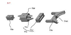
도 7은 본 발명 실시 예에 따른 안전 스윙 스틱 텐션장치의 일구성인 스윙모듈의 일 구성인 관절회동부재의 분해사시도이며,
도 8은 본 발명 실시 예에 따른 안전 스윙 스틱 텐션장치의 일구성인 스윙모듈의 일 구성인 회전수단의 분해사시도이고,
도 9는 본 발명 실시 예에 따른 안전 스윙 스틱 텐션장치의 분해사시도이다.Fig. 1 is an exploded perspective view and a roll sectional view of a conventional roll blind, which is a type of hoist machine,
2 is an exploded perspective view showing a conventional clutch for both rolls,
Fig. 3 is a cross-sectional view of the conventional roll-to-roll clutch and the rotary bar in the engaged state,
FIG. 4 is a perspective view of a sunroof driving device having a return function of a driving wheel member according to the present invention,
5 is an assembled perspective view of a safety swing-stick tensioning device according to an embodiment of the present invention,
FIG. 6 is a schematic view illustrating a swing module incorporating a safety swing stick tension device according to an embodiment of the present invention,
FIG. 7 is an exploded perspective view of a joint pivoting member, which is a constitution of a swing module which is a constitution of a safety swing stick tensioning device according to an embodiment of the present invention,
FIG. 8 is an exploded perspective view of a rotating means, which is a constitution of a swing module which is a constitution of a safety swing stick tension device according to an embodiment of the present invention,
9 is an exploded perspective view of a safety swing-stick tension device according to an embodiment of the present invention.
이하에서는, 첨부도면을 참고하여 본 발명에 따른 바람직한 실시예를 보다 상세하게 설명하기로 한다.
Hereinafter, preferred embodiments of the present invention will be described in detail with reference to the accompanying drawings.
다만, 첨부된 도면은 본 발명의 내용을 보다 쉽게 개시하기 위하여 설명되는 것일 뿐, 본 발명의 범위가 첨부된 도면의 범위로 한정되는 것이 아님은 당해 기술 분야의 통상의 지식을 가진 자라면 용이하게 알 수 있을 것이다.
It is to be understood that both the foregoing general description and the following detailed description are exemplary and explanatory only and are not restrictive of the invention, You will know.
첨부된 도면들에서 구성에 표기된 참조번호는 다른 도면에서도 동일한 구성을 표기할 때에 가능한 한 동일한 도면번호를 사용하고 있음에 유의해야 한다. 또한, 본 발명을 설명함에 있어 관련된 공지의 기능 또는 공지의 구성에 대한 구체적인 설명이 본 발명의 요지를 불필요하게 흐릴 수 있다고 판단되는 경우에는 그 상세한 설명을 생략하기로 한다. 그리고 도면에 제시된 어떤 특징들은 설명의 용이함을 위해 확대 또는 축소 또는 단순화된 것이고, 도면 및 그 구성요소들이 반드시 적절한 비율로 도시되어 있지는 않다. 또한, 장치 또는 요소의 방향에 있어서, 전후좌우, 상하, 종횡은 본 발명의 설명을 용이하게 하기 위한 것으로 관련된 장치 또는 요소가 특정방향을 가져야 함을 의미하지 않는다. 아울러, "제 1", "제 2" 와 같은 용어는 설명의 편의를 위해 사용되는 것으로 상세한 설명 및 청구항 들에서 상대적인 주요성 또는 취지 또는 순서를 의미하는 것은 아니다. 이러한 사항은 당업자라면 이에 대한 상세 사항들을 쉽게 이해할 것이다. It should be noted that reference numerals used in the drawings in the accompanying drawings use the same reference numerals whenever possible, in other drawings. In the following description of the present invention, a detailed description of known functions and configurations incorporated herein will be omitted when it may make the subject matter of the present invention rather unclear. And certain features shown in the drawings are to be enlarged or reduced or simplified for ease of explanation, and the drawings and their components are not necessarily drawn to scale. Further, in terms of the orientation of the device or element, front, rear, left, top and bottom, top and bottom are intended to facilitate the description of the present invention and do not imply that the associated device or element should have a particular orientation. Furthermore, terms such as " first "and" second "are used for convenience of description and are not meant to imply a relative main cause or purpose or order in the detailed description and claims. Such details will be readily apparent to those skilled in the art.
본 발명 실시 예에 따른 안전 스윙 스틱 텐션장치(7, Safety swing stick tension device)는 도 5 및 도 6 그리고 도7, 도 8, 도 9에 도시한 바와 같이, 회전줄(3)을 가지는 구동휠 부재의 복귀 기능을 갖는 차양구동장치(4b, 이하 “차양구동장치”라 칭함))에 단단히 결합되고 소정각도 회전하며 차양구동장치(4b)로부터 하부 아래 외부로 노출되는 회전줄(3) 부위가 소정 각도로 외부에 위치시키도록 안내하는 스윙모듈(71); 결합부재(72d)에 의해 상기 스윙모듈(71)에 일 측 끝단에 몸체(72a)가 단단히 결합되어지고 몸체(72a)는 그 일부가 다단으로 겹쳐 신축 및 그 반대로는 신장이 가능하되 도시하지 않은 길이고정부재로 소정 길이로 제한될 수 있거나 소정 길이를 가지는 하나로 기다란 막대기모양으로 중실체 혹은 중공체로 일체 성형되어지며 회전줄(3a)이 상기 스윙모듈(71)에 결합되어지는 일 측 반대편 타단에 구비되는 회전수단(72b)에 의해 회동 가능하도록 팽팽하게 걸쳐져 지지되어지고, 몸체(72a)의 중간에는 회전줄(3)을 외력으로 잡아당길 때 회전줄(3)이 몸체(72a)로부터 벌어지는 폭이 제한되도록 구속하기 위해 결합부재(72d)와 회전수단(72b) 사이에 몸체(72a)에 고정되는 줄구속부재(72c)가 구비된 텐션스틱모듈(72);를 포함하여, 차양구동장치(4b) 하방으로 늘어진 회전줄(3)과 회전줄(3) 사이 혹은 회전줄(3)과 몸체(72a) 사이에서 어린아이의 머리가 끼어져 들어가지 않도록 회전줄(3)을 구속하여 안전을 도모함과 동시에 스윙모듈(71)에 의해 차양구동장치(4b)로부터 소정각도 이격된 하방 위치에서도 편리하게 회전줄(3)을 잡아당겨 차양구동장치(4b)를 구동하게 하는 특징이 있다.
5 and 6 and 7, 8 and 9, the safety swing stick tension device 7 according to the embodiment of the present invention is a safety swing stick tension device, A portion of the rotary string 3 which is tightly coupled to the sun shade driving device 4b (hereinafter referred to as " a shovel driving device ") having a function of returning the member and is rotated at a predetermined angle, A swing module (71) for guiding the swing module (70) to be positioned outside at a predetermined angle; The body 72a is firmly coupled to the swing module 71 at one end by the engaging member 72d and a part of the body 72a is stretched in multiple stages so that it can be stretched and expanded and vice versa, The swinging member 71 is integrally formed with the middle or the hollow body in the form of a long bar having a predetermined length or may be limited to a predetermined length by a length fixing member, And the width of the rotary string 3 extending from the body 72a when the rotary string 3 is pulled by an external force is supported at a middle portion of the body 72a so as to be rotatable by the rotary means 72b provided, And a tension restricting member 72 provided with a line restricting member 72c fixed to the body 72a between the engaging member 72d and the rotating means 72b so as to restrain the rest 4b) downwardly pivoting rope (3) So that the head of the child is prevented from being caught between the rotary string 3 and the rotary string 3 or between the rotary string 3 and the body 72a, And is also characterized in that the rotating shaft 3 is pulled easily to drive the awning driving device 4b even in a lower position spaced apart from the awning driving device 4b by a predetermined angle.
또한, 스윙모듈(71)은 도 6, 도 7에 상세하게 도시한 바와 같이, 호형상의 회동슬롯(71a1) 혹은 도시하지 않은 돌출형상의 고정자가 구비되어 있으며 차양구동장치(4b)에 결합되거나 일체로 형성되는 스윙고정자(71a); 상기 스윙고정자(71a)의 회동슬롯(71a1)이나 고정자에 소정각도 회동 가능하도록 결합되는 회동자(71b1)가 구비된 대략 ‘Y’자 형상으로 회전줄(3)을 외부로 안내하는 스윙회동자(71b);를 포함하여 이루어지며, 좌우 혹은 상하로 텐션스틱모듈(72) 전체가 더 큰 각도로 회동할 수 있도록 제 1, 2 회동관절(71c’)(71c“)로 구비되는 관절회동부재(71c)를 더 포함할 수 있는데, 본 발명 실시 예에서는 이를 포함하여 구비하되 사각형상의 중공체의 몸체(72a) 및 결합부재(72d)에 제 2회동관절(71c“)을 일체로 형성하여 마련하며, 스윙고정자(71a)는 차양구동장치(4b)의 상하게이스 하단에 일체로 형성하며 그 하단 소정위치에는 스윙회동자(71b)의 회동자(71b1)가 끼워져 소정각도 회동하도록 호형상의 관통된 회동슬롯(71a1)으로 구비하며, 제 1,2회동관절(71c’)(71c“)로 구비되는 관절회동부재(71c)는 당업자가 쉽게 이해하는 부품이므로 이에 대하여는 자세한 설명을 생략하기로 한다.
6 and 7, the
뿐만 아니라 상기 회전수단(72b)은 텐션스틱모듈(72)의 몸체(72a)의 하단중공에 진입시켜 끼워지는 소정길이의 조절상단부(72b1a)와 회전줄이(3)이 회동하는 회동부(72b1b) 및 버클이 형성된 버클수하단부(72b1c)가 일체로 형성된 회전부재(72b1); 회전부재(72b1)의 버클수하단부(72b1c)에 결합되는 버클암케이스(72b2);를 포함하며, 회동부(72b1b)와는 이격된 위치에 도시하지 않은 로터부재를 더 포함할 수 있으며, 본 발명에서는 로터부재(미도시) 없이 회동부(72b1b)로만 구비하며, 결합방법으로는 회전부재(72b1)의 조절상단부(72b1a)를 먼저 텐션스틱모듈(72)의 몸체(72a)에 끼우고 회전줄(3)을 회동부(72b1b)에 팽팽하도록 걸쳐 끼운 후에 몸체(72a)에 피스를 박아 조절상단부(72b1a)까지 단단하게 몸체(72a)에 고정시키며 이어서 회전부재(72b1)의 버클수하단부(72b1c)에 버클암케이스(72b2)를 끼워 마련한다.
The rotating means 72b is provided with an adjusting upper end portion 72b1a of a predetermined length to be inserted into the lower end hollow of the
한편, 차양구동장치(4b)의 조립 등은 선행기술을 참조하면 되므로 생략하기로 하며 전체적으로 본 발명에 따른 안전 스윙 스틱 텐션장치(7)의 조립은 도 5 및 도 9를 참고하여 설명하고자 하며, 먼저 차양구동장치(4b)의 상하케이스 조립할 때에 회전줄(3)이 외부로 인출되어지되 스윙회동자(71b) 내부를 통과하도록 조립한 후에 제 1회동관절(71c‘)까지 통과시키고 제 1회동관절(71c‘)을 스윙회동자(71b)에 결합시키며 제 2회동관절(71c“)과 텐션스틱모듈(72)의 몸체(72a)까지 통과시킨 후에 결합부재(72d)를 몸체(72a)에 피스로 단단히 고정시킨 후 제 1회동관절(71c‘)에 제 2회동관절(71c“)을 결합시킨다.
5 and 9, the assembly of the safety swing
또한, 줄구속부재(72c)를 하단으로 늘어져 있는 회전줄(3) 및 텐션스틱모듈(72)의 몸체(72a)의 하단에서부터 소정 높이 까지 통과시켜 사전에 끼워두며, 상술한 바와 같이 회전수단(72b)을 조립한 후에 최종적으로 줄구속부재(72c)를 피스로 텐션스틱모듈(72)의 몸체(72a)에 고정한다. 이때 회전줄(3)은 줄구속부재(72c)의 내부에서 상하로의 이동은 자유롭지만 줄을 밖으로 잡아당기면 제한되도록 구비된다.
The
이하, 이와 같은 구성을 가진 본 발명 실시예의 안전 스윙 스틱 텐션장치(7)의 작동관계를 설명하기로 하되, 롤 블라인드 스크린 등은 도시하지 않기로 하며, 이는 당업자가 쉽게 이해할 수 있으므로 이하 그 구성이나 작동에 대한 자세한 설명은 생략하기로 한다.
Hereinafter, the operation of the safety swing
먼저, 사용자는 육안으로 안전커버장치(7)의 밖으로 인출되어 있는 회전줄(3)을 식별(승강 혹은 하강작동 식별)하여 잡고 한 스트로크 길이에 해당하는 회전줄(3)을 당기면 당겨지는 길이만큼 회전줄 풀리(도 9 참조)를 회전시켜 호이스트기기의 회전축(미도시)을 돌리게 되고 하방으로 당겨진 회전줄(3)이 회전수단(72b)의 회동부(72b1b)를 타고 돌아 상승하지만 여전히 안전커버장치(7) 외부로 노출된 회전줄(3)이 당겨지더라도 몸체(72a)로부터 이격되지 않아서 구속되므로 어린이는 회전줄(3)에 안전한 것이며, 사용자가 잡아당김을 멈추면 구동휠 부재의 복귀 기능을 갖는 차양구동장치(4b)에 의해 잡아당겨진 회전줄(3)이 역회전되면서 동시에 회전수단(72b)의 회동부(72b1b)를 타고 돌아 역회전하며 사용자는 회전줄(3)을 다시 파지하지 않고 연속동작으로 차양을 구동한다. 이때 팽팽하게 당겨진 회전줄(3)이라 하여도 90cm이상일 경우 회전줄(3)의 이동방향과 수직으로 잡아당기면 회전줄(3)의 장력특성에 의해 20cm이상 몸체(72a)로부터 이격되므로 줄구속부재(72c)를 통해 회전수단(72b)과 줄구속부재(72c)의 거리를 90cm이하로 제한하므로 해당길이에서는 어린이에게 매우 안전한 것이며, 차양구동장치(4b)와 떨어진 각도의 하방 바닥에서도 안전커버장치(7)를 용이하게 파지하도록 소정각도 회전시켜 손쉽게 차양을 구동할 수 있게 한 유용한 발명인 것이다.
First, the user identifies (ascends or descends) the
뿐만 아니라, 본 발명에 따른 안전커버장치(7)는 구동휠 부재의 복귀 기능을 갖는 차양구동장치(4b)가 아닌 기존 루프 차양구동장치에도 사용 가능하며, 이때는 파지한 회전줄(3)을 놓아 손을 들어올려 다시 파지하는 방식으로 구동시키므로 불편함을 제외하면 역시 어린이의 안전에 크게 기여할 수 있음은 물론 호이스트장치의 구동에 편리함은 당업자도 쉽게 이해할 수 있을 것이다.
In addition, the
예컨대, 본 발명에 따른 안전커버장치(7)는 루프 회전줄 방식 혹은 회전줄을 역회전시키는 방식의 어린이 안전 호이스트구동장치에 사용되면 매우 유용하며, 롤/콤비/트리플 블라인드의 소정 너비와 높이를 가진 스크린의 일 측 끝단을 권취부재인 소정 직경의 봉에 승강 권취 및 하강 권해하는 방식으로 차광 및 채광하는 롤 블라인드와 어닝 장치, 다수 슬랫을 걷거나 펼치도록 최하단 지지부재에 견인줄의 일 측 하단을 묶고 다수 슬랫에 형성된 구멍으로 상단 슬랫까지 삽입되어진 견인줄의 상단 일 측 끝단을 권취부재에 승강 권취하거나 하강 권해하는 방식으로 슬랫을 차곡차곡 끌어 걷어 올리거나 내리도록 하여 차광 및 채광하는 베니션 블라인드, 또 주름진 스크린의 하단에 구비된 지지부재에 견인줄의 일 측 하단을 묶고 견인줄의 상단 일 측 끝단을 권취부재에 승강 권취하거나 하강 권해하는 방식으로 주름 스크린을 펼치거나 접어서 차광 혹은 채광하는 허니콤 및 플리티드 블라인드 등으로 대표되는 차양, 지지부재에 소정길이의 견인줄 일 측단을 묶고 권취부재에 타 끝단을 묶은 후에 지지부재에 널려지는 빨래를 들어 올리거나 내리기 위해 견인줄을 권취하거나 권해하는 빨래건조대 등과 같은 소형 호이스트 기기의 중량물에 의한 하강 혹은 그로 인한 권취부재의 회동 및 중량물의 승강 혹은 하강 구동을 위해 사용하면 어린이 안전에 매우 유용하다 할 것이다.
For example, the
부연하여 설명하면, 상기 차양구동장치(4b)는, 일례로 본 발명자의 상기 등록특허 10-1295684 및 등록특허 10-1469910호의 양방향구동 클러치를 구성하는 리테이너를 역회전시키는 역회전수단을 더 포함한 구동휠 부재의 복귀 기능을 갖는 차양구동장치를 참조하면 되며, 상기 차양구동장치(4b)의 풀리에 회전줄(3)의 결합 관계는, 일례로 본 발명자의 상기 특허출원 제2013-17174호의 기술을 적용하여 당업자라면 충분히 재현할 수 있다.
In further detail, the sun
이처럼, 앞에서 설명된 본 발명의 실시예들은 본 발명의 기술적 사상을 한정하는 것으로 해석되어서는 안 된다. 본 발명의 보호범위는 청구범위에 기재된 사항에 의하여만 제한되고, 본 발명이 속하는 기술 분야에서 통상의 지식을 가진 자는 본 발명의 기술적 사상을 다양한 형태로 개량 변경하는 것이 가능하다. 따라서 이러한 개량 및 변경은 통상의 지식을 가진 자에게 자명한 것인 한 본 발명의 보호범위에 속하게 될 것이다.
As described above, the embodiments of the present invention described above should not be construed as limiting the technical idea of the present invention. The scope of protection of the present invention is limited only by the matters described in the claims, and those skilled in the art will be able to modify the technical idea of the present invention in various forms. Accordingly, such improvements and modifications will fall within the scope of the present invention as long as they are obvious to those skilled in the art.
3 : 회전줄
4b : 차양구동장치
7 : 안전 스윙 스틱 텐션장치
71 : 스윙모듈
71a : 스윙 고정자
71a' : 하 케이스
71a" : 상 케이스
71b : 스윙 회전자
71c : 관절회동부재
71c' : 제1 회동관절
71c" : 제2 회동관절
72 : 텐션스틱모듈
72a : 몸체
72b : 회전수단
72c : 줄 구속부재
72d : 결합부재3:
7: Safety swing stick tension device 71: Swing module
71a:
71a ":
71c: joint articulating
71c ": second rotating joint 72: tension stick module
72a:
72c:
Claims (8)
결합부재(72d)에 의해 상기 스윙모듈(71)에 기다란 막대 모양의 몸체(72a)가 결합되어지고, 상기 회전줄(3a)이 상기 스윙모듈(71)에 결합되어지는 일 측면의 반대편 타단에 구비되는 회전수단(72b)에 의해 회동 가능하도록 팽팽하게 걸쳐져 지지되어지는 텐션스틱모듈(72);
을 포함하여,
상기 차양구동장치(4b) 하방으로 늘어진 회전줄(3)과 회전줄(3) 사이 혹은 회전줄(3)과 몸체(72a) 사이에서 어린아이의 머리가 끼어져 들어가지 않도록 회전줄(3)을 구속함과 동시에, 상기 스윙모듈(71)에 의해 상기 차양구동장치(4b)로부터 소정각도 이격된 하방 위치에서도 상기 회전줄(3)을 잡아당겨 차양구동장치(4b)를 구동하는 것이 가능한 것을 특징으로 하는 차양구동장치의 안전 스윙 스틱 텐션장치.Is connected to the sunshade driving device 4b having a function of returning the driving wheel member having the rotation string 3 and is rotated at a predetermined angle and is drawn into the sunshield driving device 4b and drawn out from the sunshield driving device 4b A swing module (71) for guiding a portion of the rotary string (3) to be positioned outside at a predetermined angle; And
The swing module 71 is coupled with the elongated bar body 72a by the engaging member 72d and the swing module 71 is coupled to the swing module 71 at the other end opposite to the one side A tension stick module 72 which is stretched and supported so as to be rotatable by the rotation means 72b provided;
Including,
The rotary string 3 is provided between the rotary string 3 and the rotary string 3 or between the rotary string 3 and the body 72a so that the head of the child is not caught between the rotary string 3 and the rotary string 3, And it is also possible to drive the sun shade driving device 4b by pulling the rotary string 3 at a lower position spaced apart from the sun shade driving device 4b by a predetermined angle by the swing module 71 Characterized in that the safety swing stick tensioning device of the shovel driving device.
상기 몸체(72a)는, 그 일부가 다단으로 겹쳐 신축 및 신장이 가능하도록 구성된 것을 특징으로 하는 차양구동장치의 안전 스윙 스틱 텐션장치.The method according to claim 1,
Wherein the body (72a) is configured so that a part of the body (72a) can be stretched and stretched in multiple stages.
상기 텐션스틱모듈(72)은, 몸체(72a)의 중간에는 회전줄(3)을 외력으로 잡아당길 때 회전줄(3)이 몸체(72a)로부터 벌어지는 폭이 제한되도록 구속하기 위해 결합부재(72d)와 회전수단(72b) 사이에 몸체(72a)에 고정되는 줄구속부재(72c)가 더 구비된 것을 특징으로 하는 차양구동장치의 안전 스윙 스틱 텐션장치.The method according to claim 1,
The tension stick module 72 is provided at an intermediate portion of the body 72a with an engaging member 72d for restricting the width of the rotary string 3 from the body 72a when the rotary string 3 is pulled by external force, Further comprising a line-restraining member (72c) fixed to the body (72a) between the rotation means (72b) and the rotation means (72b).
상기 스윙모듈(71)은,
회동슬롯(71a1)나 별도의 돌출형상의 고정자가 구비되어 있으며 상기 차양구동장치(4b)에 결합되거나 일체로 형성되는 스윙고정자(71a); 및
상기 스윙고정자(71a)의 회동슬롯(71a1)이나 고정자에 소정각도 회동 가능하도록 결합되는 회동자(71b1)가 구비되며 상기 회전줄(3)을 외부로 안내하는 스윙회동자(71b);
를 포함하여 이루어지는 것을 특징으로 하는 차양구동장치의 안전 스윙 스틱 텐션장치.The method according to claim 1,
The swing module (71)
A swing stator 71a having a rotation slot 71a1 or a separate protruding stator and coupled to or integrally formed with the awning drive device 4b; And
A swinging rotator 71b having a rotary slot 71a1 of the swing stator 71a and a rotary element 71b1 coupled to the stator so as to be rotatable by a predetermined angle and guiding the rotary element 3 to the outside;
And a safety swing stick tensioning device for swinging the safety shoe.
상기 스윙모듈(71)은,
좌우 혹은 상하로 상기 텐션스틱모듈(72) 전체가 더 큰 각도로 회동할 수 있도록 제 1 회동관절(71c’) 및 제 2 회동관절(71c“)로 이루어지는 관절회동부재(71c)를 더 포함하는 것을 특징으로 하는 차양구동장치의 안전 스윙 스틱 텐션장치.5. The method of claim 4,
The swing module (71)
Further comprising an articulating torsion member 71c including a first articulation joint 71c 'and a second articulation joint 71c' so that the entirety of the tension stick module 72 can be pivoted at a larger angle in left and right or up and down directions Wherein the safety swing stick tension device comprises:
상기 회전수단(72b)은,
상기 텐션스틱모듈(72)의 몸체(72a)의 하단 중공에 진입시켜 끼워지는 조절상단부(72b1a)와 상기 회전줄이(3)이 회동하는 회동부(72b1b) 및 버클이 형성된 버클수하단부(72b1c)가 일체로 형성된 회전부재(72b1); 및
상기 회전부재(72b1)의 버클수하단부(72b1c)에 결합되는 버클암케이스(72b2);를 포함하는 것을 특징으로 하는 차양구동장치의 안전 스윙 스틱 텐션장치.The method according to claim 1,
The rotating means (72b)
An adjusting upper portion 72b1a which is inserted into the lower end hollow of the body 72a of the tension stick module 72 and a rotary portion 72b1b in which the rotary string 3 rotates and a buckle lower end portion 72b1c A rotary member 72b1 integrally formed with the rotary member 72b1; And
And a buckle arm case (72b2) coupled to the buckle lower end (72b1c) of the rotary member (72b1).
Priority Applications (1)
| Application Number | Priority Date | Filing Date | Title |
|---|---|---|---|
| KR1020150123867A KR20170027219A (en) | 2015-09-01 | 2015-09-01 | A safety swing stick tension device of a shade drive apparatus, and the shade drive apparatus and hoist apparatus using the same |
Applications Claiming Priority (1)
| Application Number | Priority Date | Filing Date | Title |
|---|---|---|---|
| KR1020150123867A KR20170027219A (en) | 2015-09-01 | 2015-09-01 | A safety swing stick tension device of a shade drive apparatus, and the shade drive apparatus and hoist apparatus using the same |
Publications (1)
| Publication Number | Publication Date |
|---|---|
| KR20170027219A true KR20170027219A (en) | 2017-03-09 |
Family
ID=58402581
Family Applications (1)
| Application Number | Title | Priority Date | Filing Date |
|---|---|---|---|
| KR1020150123867A Withdrawn KR20170027219A (en) | 2015-09-01 | 2015-09-01 | A safety swing stick tension device of a shade drive apparatus, and the shade drive apparatus and hoist apparatus using the same |
Country Status (1)
| Country | Link |
|---|---|
| KR (1) | KR20170027219A (en) |
Cited By (1)
| Publication number | Priority date | Publication date | Assignee | Title |
|---|---|---|---|---|
| CN110258982A (en) * | 2019-07-02 | 2019-09-20 | 福州市规划设计研究院 | It can carry out the building intelligence shading system of optical illumination and gravity-flow ventilation |
-
2015
- 2015-09-01 KR KR1020150123867A patent/KR20170027219A/en not_active Withdrawn
Cited By (2)
| Publication number | Priority date | Publication date | Assignee | Title |
|---|---|---|---|---|
| CN110258982A (en) * | 2019-07-02 | 2019-09-20 | 福州市规划设计研究院 | It can carry out the building intelligence shading system of optical illumination and gravity-flow ventilation |
| CN110258982B (en) * | 2019-07-02 | 2024-04-02 | 福州市规划设计研究院集团有限公司 | Intelligent building sunshade system capable of conducting light guide illumination and natural ventilation |
Similar Documents
| Publication | Publication Date | Title |
|---|---|---|
| KR101469910B1 (en) | A Shade Drive Apparatus having the function in which the driving wheel can be returned | |
| US8590592B2 (en) | Roll blind having noiseless bidirectional clutch | |
| KR101542597B1 (en) | A clutch Assembly | |
| US5485875A (en) | Window shade with break-away attachment of lift cords to bottom rail | |
| KR101906028B1 (en) | Window shade and actuating system thereof | |
| KR20130038855A (en) | Operation device for solar shading device, lifting device for roll-up shade, and operating pulley | |
| JP2004183462A (en) | Curtain lifting control device and control method | |
| JP2003184456A (en) | Operating cord for sun shade member | |
| US9140060B2 (en) | Window covering having at least one deformable connector | |
| US9187952B2 (en) | Cordless blind system and retro-fit method | |
| KR101299397B1 (en) | Roll blind apparatus having a saparated type safety cord | |
| KR101213737B1 (en) | Roll blind apparatus having a safety cord | |
| KR20170027219A (en) | A safety swing stick tension device of a shade drive apparatus, and the shade drive apparatus and hoist apparatus using the same | |
| KR20180066644A (en) | Roll-Screen Blind Lifting Device | |
| US20120305200A1 (en) | Safe Window Blind | |
| JP2021055484A (en) | Shielding device | |
| CA2814575C (en) | Blind assembly | |
| JP5315009B2 (en) | blind | |
| KR20190090667A (en) | A safety device module for a hoist device and the hoist device using the same | |
| KR101195828B1 (en) | Winding apparatus for blind | |
| KR20190089465A (en) | A two-way clutch module for a hoist device and the hoist device using the same | |
| KR20170050200A (en) | A clutch device of a hoist apparatus and hoist apparatus using the same | |
| KR20070082595A (en) | Roll blind drive with double spring | |
| KR20160117301A (en) | A safety wheel rope assembly of a hoist drive apparatus and the cover used to the same, and the hoist apparatus using the same | |
| KR20150124300A (en) | A ball-chain hybrid cord and the clutch device using the same |
Legal Events
| Date | Code | Title | Description |
|---|---|---|---|
| PA0109 | Patent application |
Patent event code: PA01091R01D Comment text: Patent Application Patent event date: 20150901 |
|
| PG1501 | Laying open of application | ||
| PC1203 | Withdrawal of no request for examination |